ventilation equipment - bvt · 5 horizontal electric heater domekt p vertical water heater none...
TRANSCRIPT

VENTILATION EquIpmENT

VENTILATION EQUIPMENT

2
6115
Verso R Standard 64Verso R 1200 U/H/V 66Verso R 1200 F 67Verso R 1400 U/H/V 68Verso R 1600 U/H/V 69Verso R 2000 U/H/V 70Verso R 2000 F 71Verso R 2500 U/H/V 72Verso R 3000 U/H/V 73Verso R 4000 U/H/V 74Verso R 4500 U/H/V 75Verso R 7000 H 76Verso P Standard 77Verso P 1600 F 78Verso CF Standard 79Verso CF 1300 U/H/V 81Verso CF 1300 F 82Verso CF 1500 F 83Verso CF 1700 U/H/V 84Verso CF 2300 U/H/V 85Verso CF 3500 U 86Verso S Standard 87Verso S 1300 F 88Verso S 2100 F 89Verso S 3000 F 90Verso S 4000 F 91Accessories 125Verso Pro 92
VERSONon residential ventilation units1000 – 34 000 m³/h
Domekt R 17Domekt R 200 V 19Domekt R 250 F New automatic C6 20Domekt R 300 V New unit 21Domekt R 400 V New automatic C6 22Domekt R 400 H New automatic C6 23Domekt R 400 F New automatic C6 24Domekt R 450 V New automatic C6 25Domekt R 500 V New automatic C6 26Domekt R 500 H New automatic C6 27Domekt R 600 U 28Domekt R 600 H New automatic C6 29Domekt R 700 V New automatic C6 30Domekt R 700 H New automatic C6 31Domekt R 700 F New automatic C6 32Domekt R 900 U/H/V 33Domekt P 34Domekt PP 300 V 36Domekt P 400 V 37Domekt P 400 H 38Domekt PP 450 V 39Domekt P 700 V 40Domekt P 700 H 41Domekt P 900 V 42Domekt P 900 H 43Domekt CF 44Domekt CF 250 V 46Domekt CF 250 F New automatic C6 47-48Domekt CF 400 V New automatic C6 49-50Domekt CF 500 F New automatic C6 51-52Domekt CF 700 V New automatic C6 53Domekt CF 700 H New automatic C6 54Domekt CF 900 U/H/V 55Domekt CF 900 F 56Domekt S 57Domekt S 650 F 58Domekt S 800 F 59Domekt S 1000 F 60Accessories 125
CONTENT
DOMEKTResidential ventilation units50–1 000 m³/h
3
99 115
KLASIK 116Klasik R 117Klasik P 117Klasik RA 117Klasik CF New unit 118Klasik Hg 118Klasik S 118
CONTENT
RHP Standard 103RHP 400 V 104RHP 600 U 106RHP 800 U 108RHP 1300 U 110RHP 1500 U 112RHP Pro 114Accessories 125
RHPVentilation units with a rotary heat exchanger and an integrated heat pump150 – 25 000 m³/h
KLASIKNon residential ventilation units1 000 – 90 000 m³/h
4 UAB AMALVA reserves the right to introduce the changes of parameters and sizes in the process of improvement of the air handling units.KK2-
17-0
2
ADVANTAGES
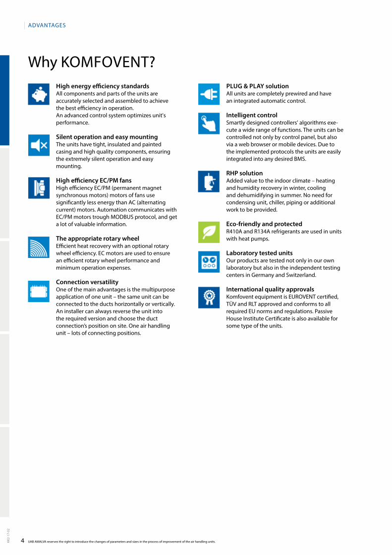
Why KOMFOVENT?High energy efficiency standardsAll components and parts of the units are accurately selected and assembled to achieve the best efficiency in operation. An advanced control system optimizes unit's performance.
Silent operation and easy mountingThe units have tight, insulated and painted casing and high quality components, ensuring the extremely silent operation and easy mounting.
High efficiency EC/PM fansHigh efficiency EC/PM (permanent magnet synchronous motors) motors of fans use significantly less energy than AC (alternating current) motors. Automation communicates with EC/PM motors trough MODBUS protocol, and get a lot of valuable information.
The appropriate rotary wheelEfficient heat recovery with an optional rotary wheel efficiency. EC motors are used to ensure an efficient rotary wheel performance and minimum operation expenses.
Connection versatilityOne of the main advantages is the multipurpose application of one unit – the same unit can be connected to the ducts horizontally or vertically. An installer can always reverse the unit into the required version and choose the duct connection’s position on site. One air handling unit – lots of connec ting positions.
PLug & PLAy solution All units are completely prewired and have an integrated automatic control.
Intelligent controlSmartly designed controllers' algorithms execute a wide range of functions. The units can be controlled not only by control panel, but also via a web browser or mobile devices. Due to the implemented protocols the units are easily integrated into any desired BMS.
RHP solution Added value to the indoor climate – heating and humidity recovery in winter, cooling and dehumidifying in summer. No need for condensing unit, chiller, piping or additional work to be provided.
Eco-friendly and protectedR410A and R134A refrigerants are used in units with heat pumps.
Laboratory tested unitsOur products are tested not only in our own laboratory but also in the independent tes ting centers in Germany and Switzerland.
International quality approvalsKomfovent equipment is EUROVENT certified, TÜV and RLT approved and conforms to all required EU norms and regulations. Passive House Institute Certificate is also available for some type of the units.
5
Horizontal
Electric heater
Domekt P
Vertical
Water heater None
Domekt CF
False ceiling
Domekt S Domekt RHPDomekt R
AHU type selection
Version 1.5.2
KK2-
17-0
2
SOFT WARE
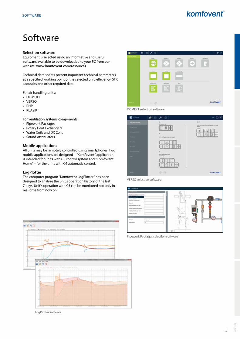
Selection software Equipment is selected using an informative and useful software, available to be downloaded to your PC from our website: www.komfovent.com/resources.
Technical data sheets present important technical para meters at a specified working point of the selected unit: efficiency, SFP, acoustics and other required data.
For air handling units: • DOMEKT• VERSO• RHP• KLASIK
For ventilation systems components:• Pipework Packages• Rotary Heat Exchangers• Water Coils and DX Coils• Sound Attenuators
Mobile applicationsAll units may be remotely controlled using smartphones. Two mobile applications are designed – ”Komfovent“ application is intended for units with C5 control system and ”Komfovent Home“ – for the units with C6 automatic control.
LogPlotterThe computer program ”Komfovent LogPlotter“ has been designed to analyze the unit's operation history of the last 7 days. Unit's operation with C5 can be monitored not only in realtime from now on.
DOMEKT selection software
VERSO selection software
LogPlotter software
Pipework Packages selection software
Software

6
C 3 C 4 C 5 C 6
UAB AMALVA reserves the right to introduce the changes of parameters and sizes in the process of improvement of the air handling units.KK2-
17-0
2
AUTOMATIC CONTROL SySTEM
Fully integrated control system KOMFOVENT ensures safe ope ration of the air handling unit, controls preset ventilation system parameters and optimize unit operating costs.
KOMFOVENT air handling units are offered by the principle PLUG & PLAy, without any external electrical boxes, ready for operation. To ensure reliable operation, reduce installation work costs and other expenses, automatic control is fully integrated in the air handling unit and the system of connected automatic elements ensures quick and easy assembling of the unit.
Everything is already prewired and tested in the manufacturing site. Only the modern and attractive design control panel must be installed inside the building in any userconvenient place.Each series of the air handling units have specially adapted KOMFOVENT controller, which in the best way ensures functionality and operational needs of the air handling unit.
Smartly designed controllers’ algorithms allow wide range of functional possibilities, which ensure energy saving of the system at the same time let to maintain and keep comfort conditions in the ventilated premises: air quality control, operation on demand, summer night cooling, VAV, CAV and many others.
Implemented Modbus and BACnet protocols allow easy integration of Komfovent air handling units to any de sired Building Management Systems.
All controllers are easy in operation, have convenient userfriendly menu, LCD display enables to monitor various parameters, touchsensitive buttons allow pleasant and convenient setting operation modes of the unit by soft touching.
Automatic control system KOMFOVENT

7
INTERNET
KK2-
17-0
2
AUTOMATIC CONTROL SySTEM
Scan the QR codes below and download mobile applications:
“Komfovent” application for units with integrated C5 control system
“Komfovent Home” application for units with integrated C6 control system
The units control system have integrated web server for controlling and monitoring the AHU’s operation via internet.
AHU can be controlled via a web browser on your compu ter or mobile devices. Application softwares for Smartphones are specially developed for more convenient control. Userfriendly interface enables clear and easy monitoring of air handling unit operation.
SMART HOUSESCADA
TABLETSMARTPHONE
Control panel C6.1
Control panel C6.2
Control panel C5.1
Control panel C5.1
COMPU TER
8 UAB AMALVA reserves the right to introduce the changes of parameters and sizes in the process of improvement of the air handling units.KK2-
17-0
2
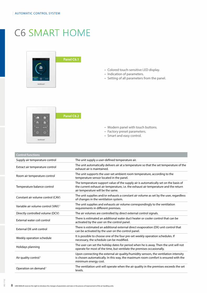
• Coloredtouch-sensitiveLEDdisplay.• Indicationofparameters.• Settingofallparametersfromthepanel.
• Modernpanelwithtouchbuttons.• Factorypresetparameters.• Smartandeasycontrol.
Control functions
Supply air temperature control The unit supply a userdefined temperature air.
Extract air temperature control The unit automatically delivers air at a temperature so that the set temperature of the exhaust air is maintained.
Room air temperature control The unit supports the userset ambient room temperature, according to the temperature sensor located in the panel.
Temperature balance controlThe temperature support value of the supply air is automatically set on the basis of the current exhaust air temperature, i.e. the exhaust air temperature and the return air temperature will be the same.
Constant air volume control (CAV) The unit supplies and/or exhausts a constant air volume as set by the user, regardless of changes in the ventilation system.
Variable air volume control (VAV) 1 The unit supplies and exhausts air volume correspondingly to the ventilation requirements in different premises.
Directly controlled volume (DCV) The air volumes are controlled by direct external control signals.
External water coil control There is estimated an additional water duct heater or cooler control that can be activated by the user on the control panel.
External DX unit control There is estimated an additional external direct evaporation (DX) unit control that can be activated by the user on the control panel.
Weekly operation schedule It is possible to choose one of the four preset weekly operation schedules. If necessary, the schedule can be modified.
Holidays planning The user can set the holiday dates for period when he is away. Then the unit will not operate for most of the time, but ventilate the premises occasionally.
Air quality control 1Upon connecting the external air quality/humidity sensors, the ventilation intensity is chosen automatically. In this way, the maximum room comfort is ensured with the minimum energy cost.
Operation on demand 1 The ventilation unit will operate when the air quality in the premises exceeds the set levels.
AUTOMATIC CONTROL SySTEM
Panel С6.2
Panel С6.1
9 KK2-
17-0
2
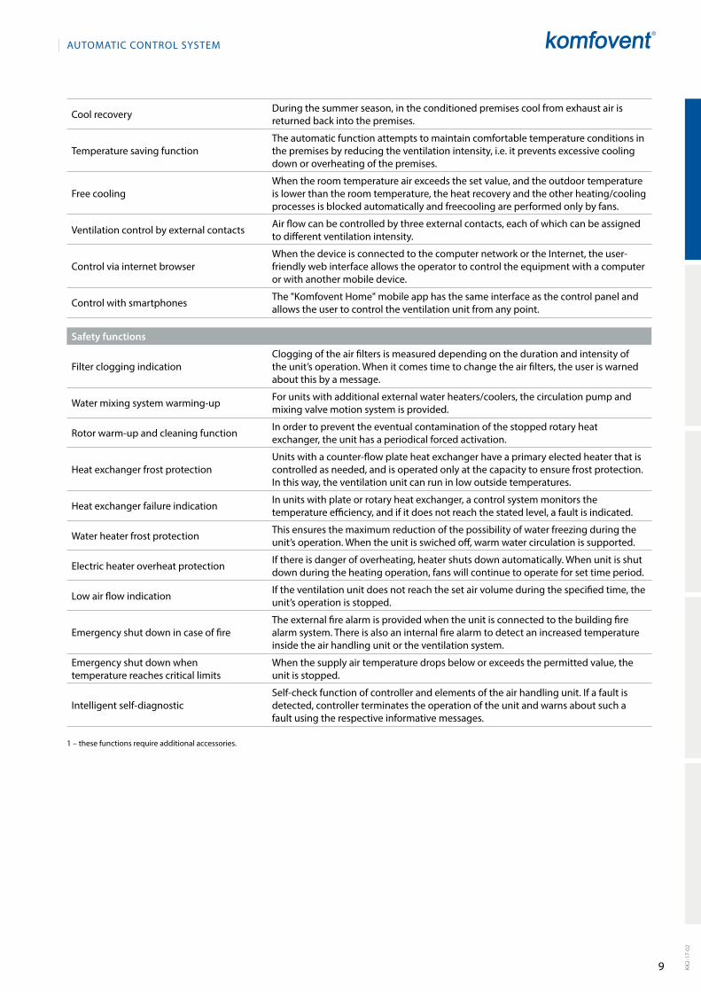
Cool recovery During the summer season, in the conditioned premises cool from exhaust air is returned back into the premises.
Temperature saving functionThe automatic function attempts to maintain comfortable temperature conditions in the premises by reducing the ventilation intensity, i.e. it prevents excessive cooling down or overheating of the premises.
Free coolingWhen the room temperature air exceeds the set value, and the outdoor temperature is lower than the room temperature, the heat recovery and the other heating/cooling processes is blocked automatically and freecooling are performed only by fans.
Ventilation control by external contacts Air flow can be controlled by three external contacts, each of which can be assigned to different ventilation intensity.
Control via internet browserWhen the device is connected to the computer network or the Internet, the userfriendly web interface allows the operator to control the equipment with a computer or with another mobile device.
Control with smartphones The "Komfovent Home" mobile app has the same interface as the control panel and allows the user to control the ventilation unit from any point.
Safety functions
Filter clogging indicationClogging of the air filters is measured depending on the duration and intensity of the unit’s operation. When it comes time to change the air filters, the user is warned about this by a message.
Water mixing system warmingup For units with additional external water heaters/coolers, the circulation pump and mixing valve motion system is provided.
Rotor warmup and cleaning function In order to prevent the eventual contamination of the stopped rotary heat exchanger, the unit has a periodical forced activation.
Heat exchanger frost protectionUnits with a counterflow plate heat exchanger have a primary elected heater that is controlled as needed, and is operated only at the capacity to ensure frost protection. In this way, the ventilation unit can run in low outside temperatures.
Heat exchanger failure indication In units with plate or rotary heat exchanger, a control system monitors the temperature efficiency, and if it does not reach the stated level, a fault is indicated.
Water heater frost protection This ensures the maximum reduction of the possibility of water freezing during the unit’s operation. When the unit is swiched off, warm water circulation is supported.
Electric heater overheat protection If there is danger of overheating, heater shuts down automatically. When unit is shut down during the heating operation, fans will continue to operate for set time period.
Low air flow indication If the ventilation unit does not reach the set air volume during the specified time, the unit’s operation is stopped.
Emergency shut down in case of fireThe external fire alarm is provided when the unit is connected to the building fire alarm system. There is also an internal fire alarm to detect an increased temperature inside the air handling unit or the ventilation system.
Emergency shut down when temperature reaches critical limits
When the supply air temperature drops below or exceeds the permitted value, the unit is stopped.
Intelligent selfdiagnosticSelfcheck function of controller and elements of the air handling unit. If a fault is detected, controller terminates the operation of the unit and warns about such a fault using the respective informative messages.
1 – these functions require additional accessories.
AUTOMATIC CONTROL SySTEM
10
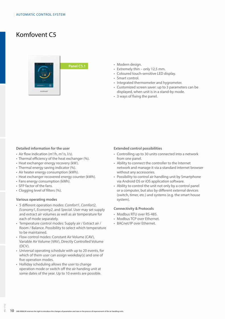
Komfovent C5
UAB AMALVA reserves the right to introduce the changes of parameters and sizes in the process of improvement of the air handling units.KK2-
17-0
2
Detailed information for the user•Airflowindication(m3/h, m3/s, l/s).•Thermalefficiencyoftheheatexchanger(%).•Heatexchangerenergyrecovery(kW).•Thermalenergysavingindicator(%).•Airheaterenergyconsumption(kWh).•Heatexchangerrecoveredenergycounter(kWh).•Fansenergyconsumption(kWh).•SFPfactorofthefans.•Cloggingleveloffilters(%).
Various operating modes• 5differentoperationmodes:Comfort1, Comfort2,
Eco nomy1, Economy2, and Special. User may set supply and extract air vo lumes as well as air temperature for each of mode separately.
• Temperaturecontrolmodes:Supplyair/Extractair/Room / Balance. Possibility to select which temperature to be maintained.
• Flowcontrolmodes:ConstantAirVolume(CAV),Variable Air Volume (VAV), Directly Controlled Volume (DCV).
• Universaloperatingschedulewithupto20events,forwhich of them user can assign weekday(s) and one of five operation modes.
• Hollidayschedulingallowstheusertochangeoperation mode or switch off the air handing unit at some dates of the year. Up to 10 events are possible.
Extended control possibilities• Controllingupto30unitsconnectedintoanetwork
from one panel. • AbilitytoconnectthecontrollertotheInternet
network and manage it via a standard internet browser without any accessories.
• PossibilitytocontrolairhandlingunitbySmartphonevia Android OS or iOS application software.
• Abilitytocontroltheunitnotonlybyacontrolpanelor a computer, but also by different external devices (switch, timer, etc.) and systems (e.g. the smart house system).
Connectivity & Protocols • ModbusRTUoverRS-485.• ModbusTCPoverEthernet.• BACnet/IPoverEthernet.
AUTOMATIC CONTROL SySTEM
• Moderndesign.• Extremelythin–only12,5mm.• Colouredtouch-sensitiveLEDdisplay.• Smartcontrol.• Integratedthermometerandhygrometer.• Customizedscreensaver:upto3parameterscanbe
displayed, when unit is in a standby mode.• 3waysoffixingthepanel.
Panel С5.1
11 KK2-
17-0
2
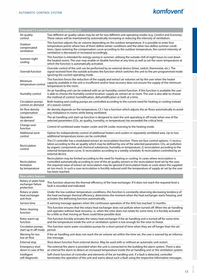
Extended C5 control functions in addition to C3
Air quality control
Two different air quality values may be set for two different unit operating modes (e.g. Comfort and Eco nomy). These values will be maintained by automatically increasing or reducing the intensity of ventilation.
Outdoor compensated ventilation
This function adjusts the air vo lume depending on the outdoor temperature. It is possible to enter four temperature points where two of them define winter conditions and the other two define summer conditions. Upon entering the compensation curve according to the outdoor temperature, the current intensity of ventilation is decreased or increased accordingly.
Summer night cooling
This function is intended for energy saving in summer: utilising the outside chill of night hours to cool down the heated rooms. The user may enable or disable function at any time as well as set the room temperature at which the function is automatically activated.
Override functionOverride control of the unit can be performed by an external device (timer, switch, thermostat, etc.). The signal received from the outside activates the function which switches the unit to the preprogrammed mode igno ring the current operating mode.
Minimum temperature control
This function forces the reduction of the supply and extract air volumes set by the user when the heater capacity available in the unit is insufficient and/or heat recovery does not ensure the supply of the minimum temperature to the room.
Humidity controlAn air handling unit can be ordered with an air humidity control function. If this function is avai lable the user is able to choose the humidity control location: supply air, extract air or room. The user is also able to choose the method of control: humidification, dehumidification or both at a time.
Circulation pumps control on demand
Both heating and cooling pumps are controlled according to the current need for heating or cooling instead of a season control.
Air flow density compensation
Air density depends on the temperature. C5.1 has a function which adjusts the air flows automatically to avoid any misba lance in rooms while being ventilated.
Operation on demand
The air handling unit startup function is designed to start the unit operating in off mode when one of the selected para meters (CO2, air quality, humidity, or temperature) has exceeded the critical limit.
Changeover function Control of combined water heater cooler and DX cooler reversing to the heating mode.
Additional zone control
Option for independently control of additional heaters and coolers in separately ventilated area. Up to two additional temperature zones can be controlled.
Recirculation control
The C5 controller has a modulated extract air recirculation function. There are four control options: 1) recirculation according to the air quality which may be defined by one of the selected parameters: CO2, air pollution by organic components and chemical substances, humidity or temperature; 2) recirculation according to the external temperature curve; 3) recirculation according to a weekly schedule; 4) recirculation controlled by an external device.
Recirculation limitation by temperature
Recirculation may be limited according to the need for heating or cooling. In cases where recirculation is controlled automatically according to one of the air quality sensors or the recirculation level set by the user, the required value of extract air recirculation may be ignored if recirculation heats or cools down the supplied air too much. In such a case recirculation is forcibly reduced until the temperature of supply air set by the user has been reached.
New safety features
Rotary or plate heat exchanger failure protection
This function observes the thermal efficiency of the heat exchanger. If it does not reach the required level a fault is recorded and indicated.
Rotary or plate heat exchanger antifrost
Under the low outdoor temperature conditions, this function is constantly observing decreasing tendency of the heat exchan ger thermal efficiency, determines the moment when the heat exchanger starts freezing, and activates the defrosting function automatically.
Service time A warning message appears when the continuous operation of the AHU has reached 12 months.
Rotor cleaning function
This function ensures that the rotary heat exchanger does not pollute when turnedoff. When the air handling unit operates without heat recovery, i.e. when the rotor does not rotate for some time, it is forcibly activated for a little so that moving air flows could blow possible dust.
Rotor warmup function
This function forcibly activates the rotary heat exchanger if the air handling unit is turned off for some time and the temperature inside the unit or ventilation system is low enough for the rotor to freeze.
Circulation pumps startup in off mode
This function starts water circulation pumps for a short period of time when they are off longer than the set period.
Warning for too low air flow
If the air handling unit does not reach the air volume set within the time set, the user is warned by an informative message.
External stop Shutdown function from external device. May be used with or without an automatic unit restart.
Emergency shutdown in case of fire
The external fire alarm is provided when the unit is connec ted to the building fire alarm system. There is also an internal fire alarm to detect an increased temperature inside the air handling unit or the ventilation system.
Intelligent selfdiagnostic
Selfcheck function of controller and elements of the air hand ling unit. If a fault is detected, controller terminates the operation of the unit and warns about such a fault using the respective informative messages.
AUTOMATIC CONTROL SySTEM
12
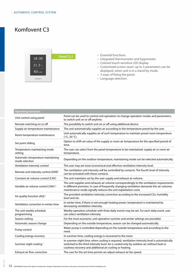
Komfovent C3
UAB AMALVA reserves the right to introduce the changes of parameters and sizes in the process of improvement of the air handling units.KK2-
17-0
2
Operating functions
Unit control using panel Panel can be used to control unit operation: to change operation modes and parameters, to switch unit on or off anytime.
Remote switching on or off The possibility to switch unit on or off using additional device.
Supply air temperature maintenance The unit automatically supplies air according to the temperature preset by the user.
Room temperature maintenance Unit automatically supplies air of such temperature to maintain preset room temperature (15...30 °C).
Set point sliding Option to shift set value of the supply or room air temperature for the specified period of time.
Temperature maintaining mode setting
The user can select from the panel temperature to be maintained: supply air or room air temperature.
Automatic temperature maintaining mode selection Depending on the outdoor temperature, maintaining mode can be selected automatically.
Ventilation intensity control The user may set most economical and effective ventilation intensity level.
Remote unit intensity control (OVR) 1 The ventilation unit intensity will be controlled by contacts. The fourth level of intensity can be activated with these contacts.
Constant air volume control (CAV) The unit maintains set by the user supply and exhaust air volume.
Variable air volume control (VAV) 2The unit supplies and exhausts air volume correspondingly to the ventilation requirements in different premises. In case of frequently changing ventilation demands this air volumes maintenance mode signally reduces the unit exploitation costs.
Air quality function (AQ) 2 The provided ventilation intensity correction according to the increased CO2, humidity level and etc.
Ventilation correction in winter time In winter time, if there is not enough heating power, temperature is maintained by decreasing ventilation intensity.
The unit weekly schedule programming
Weekly operation schedule with three daily events may be set. For each daily event, user can select ventilation intensity.
Season setting For the most economic unit operation summer and winter settings are provided.
Automatic season change Depending on the outside temperature, season can be changed automatically.
Pump control Water pump is controlled depending on the outside temperature and according to the need.
Cooling energy recovery In summer time, cooling energy is recovered to the room.
Summer night cooling 1In summer night time, when cooling is required, ventilation intensity level is automatically switched to the third intensity level. Air is cooled only by outdoor air, without heat or coolness recovery and additional air cooling or heating.
Exhaust air flow correction The user for the set time period can adjust exhaust air fan speed.
AUTOMATIC CONTROL SySTEM
• Essentialfunctions.• Integratedthermometerandhygrometer.• Coloredtouch-sensitiveLEDdisplay.• Customizedscreensaver:upto3parameterscanbe
displayed, when unit is in a standby mode.• 3waysoffixingthepanel.• Languageselection.
Panel С3.1

13 KK2-
17-0
2
Protection functions
Water heater frost protection Maximum protection from water freezing.
Electric heater overheating protectionIf there is danger of overheating, heater shuts down automatically. The unit is equipped with heater cooling. When unit is shut down during the heating operation, fans will continue to operate for set time period.
Plate heat exchanger frost protection When there is low outdoor temperature, heat exchanger is protected from freezing.
Fan overheating protection Fan motor is protected from failure.
Rotary heat exchanger rotation guard If heat exchanger has a failure, the unit operation is stopped.
Emergency shut down in case of fire If the unit is connected to the building fire alarm system, in case of fire unit operation is stopped automatically.
Emergency shut down according to the temperature value limits If supply air temperature reaches emergency level, unit operation is stopped.
Distance unit failure indication Possibility to indicate unit failure in a distance from the unit.
Return water temperature maintenance
When unit is switched off in winter time, return water temperature of 25 °C is maintained in hot water air heater.
Other functions
Filter clogging indication In case of at least one filter clogging, warning appears on the panel display.
Mode operation, temperature and time indication Supplied air filter clogging is indicated on the control panel by the red light signal.
Failure indication In case of failure of a separate unit assembly or elements, the air handling unit is stopped. This is indicated by text message.
Language selection Control panel provides menu for the language selection.
Air flow indication Option to monitor unit supply and exhaust air flow (m3/h, m3/s, l/s).
Unit PC control 1 Option to manage and control units by computer, when connected to the PC network, or Internet.
1 – additionally ordered function only for C3 control panel. 2 – accessories ordered additionally.
AUTOMATIC CONTROL SySTEM
14
Komfovent C4
UAB AMALVA reserves the right to introduce the changes of parameters and sizes in the process of improvement of the air handling units.KK2-
17-0
2
Operating functions
Unit control using panel Panel can be used to control unit operation: to change operation modes and parameters, to switch unit on or off anytime.
Supply air temperature maintenance The unit automatically supplies air according to the temperature preset by the user (15...30 ° C).
Set point sliding Option to shift set value of the supply or room air temperature for the specified period of time.
Ventilation intensity control The user may set most economical and effective ventilation intensity level.
Remote unit intensity control (OVR) The ventilation unit intensity will be controlled by contacts. The fourth level of intensity can be activated with these contacts.
The unit weekly schedule programming
Weekly operation schedule with three daily events may be set. For each daily event, user can select ventilation intensity.
Season setting For the most economic unit operation summer and winter settings are provided.
Protection functions
Water heater frost protection Maximum protection from water freezing.
Electric heater overheating protection
If there is danger of overheating, heater shuts down automatically. The unit is equipped with heater cooling. When unit is shut down during the heating operation, fans will continue to operate for set time period.
Plate heat exchanger frost protection When there is low outdoor temperature, heat exchanger is protected from freezing.
Rotary heat exchanger rotation guard If heat exchanger has a failure, the unit operation is stopped.
Emergency shut down according to the temperature value limits If supply air temperature reaches emergency level, unit operation is stopped.
Return water temperature maintenance
When unit is switched off in winter time, return water temperature of 25 °C is maintained in hot water air heater.
Other functions
Notification of service time A periodic inspection message appears on the control panel at a certain time.
Failure indication In case of failure of a separate unit assembly or elements, the air handling unit is stopped. This is indicated by text message.
Language selection Control panel provides menu for the language selection.
Unit PC control 1 Option to manage and control units by computer, when connected to the PC network, or Internet.
Control via smartphone 1 The units may be remotely controlled using ”Komfovent Home“ application, that can be downloaded from ”Google Play“.
1 – accessories ordered additionally.
AUTOMATIC CONTROL SySTEM
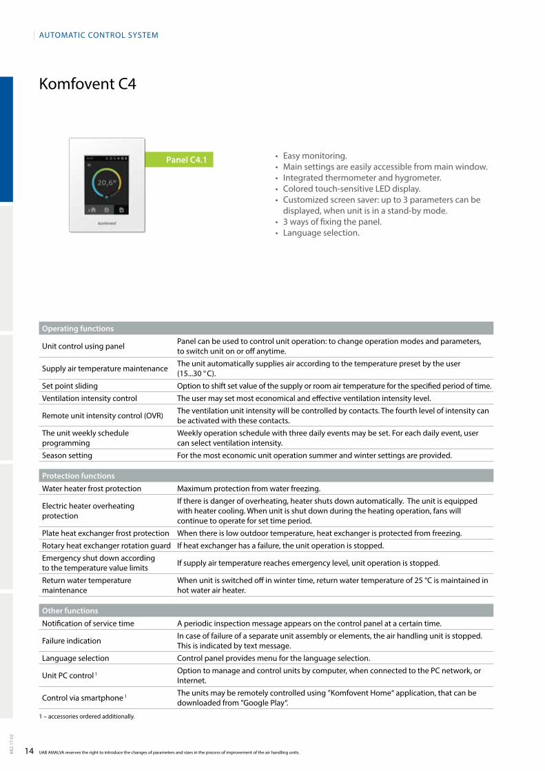
• Easymonitoring.• Mainsettingsareeasilyaccessiblefrommainwindow.• Integratedthermometerandhygrometer.• Coloredtouch-sensitiveLEDdisplay.• Customizedscreensaver:upto3parameterscanbe
displayed, when unit is in a standby mode.• 3waysoffixingthepanel.• Languageselection.
Panel С4.1

DOMEKTResidential ventilation units

16
DOMEKT
Komfovent DOMEKT
UAB AMALVA reserves the right to introduce the changes of parameters and sizes in the process of improvement of the air handling units.KK2-
17-0
2
DOMEKT air handling units (AHU) are designed for the ventilation of residential premises. DOMEKT is a standardized series of the air handling units with a heat recovery for the air flow between 50 m3/h and 1 000 m3/h.
Features and benefits of DOMEKT units:• Energy efficient solution;• PlUg & PlAy concept – units are fully prepared for
installation;• DOMEKT air handling units are especially silent;• Energy saving high performance EC fans in DOMEKT
units;• Integrated automatic control;• Wide choice of automatic control functions already
inclu ded as a standard – no options are needed;• Integrated web server for clever control;• Control via Smartphone available;• Units color – RAl 9010.
A compact air handling units' design helps to integrate them in a limited dedicated space for installation.
All DOMEKT units are based on the PlUg & PlAy principle: each unit has the integrated control system and is delivered with a complete automatic control installed and prewired inside the unit. A modern control panel is included in each supplied DOMEKT unit.
Capacity range from 50 to 1000 m3/h
Due to the availability of clever design and functions the units offer a great opportunity to keep running costslow. They are safe, reliable and durable in operation. The filtered air is supplied clean and fresh to the premises, which is extremely advisable for allergic people.
New casing technologyEPP (expanded polypropylene) advantages:
• No thermal bridges, no condensation;• Better aerodynamics;• Faster assembly;• Reduced weight;• Improved thermal insulation;• The mechanical resistance;• Special improved EPP;• Hydrophobic;• good sound insulation.
17
DOMEKT
Domekt R
0 100 200 300 400 500 600 700 800 900 1000
0 0,03 0,06 0,08 0,11 0,14 0,17 0,19 0,22 0,25 0,28
900
700
600
500
450
400
300
250
200
KK2-
17-0
2
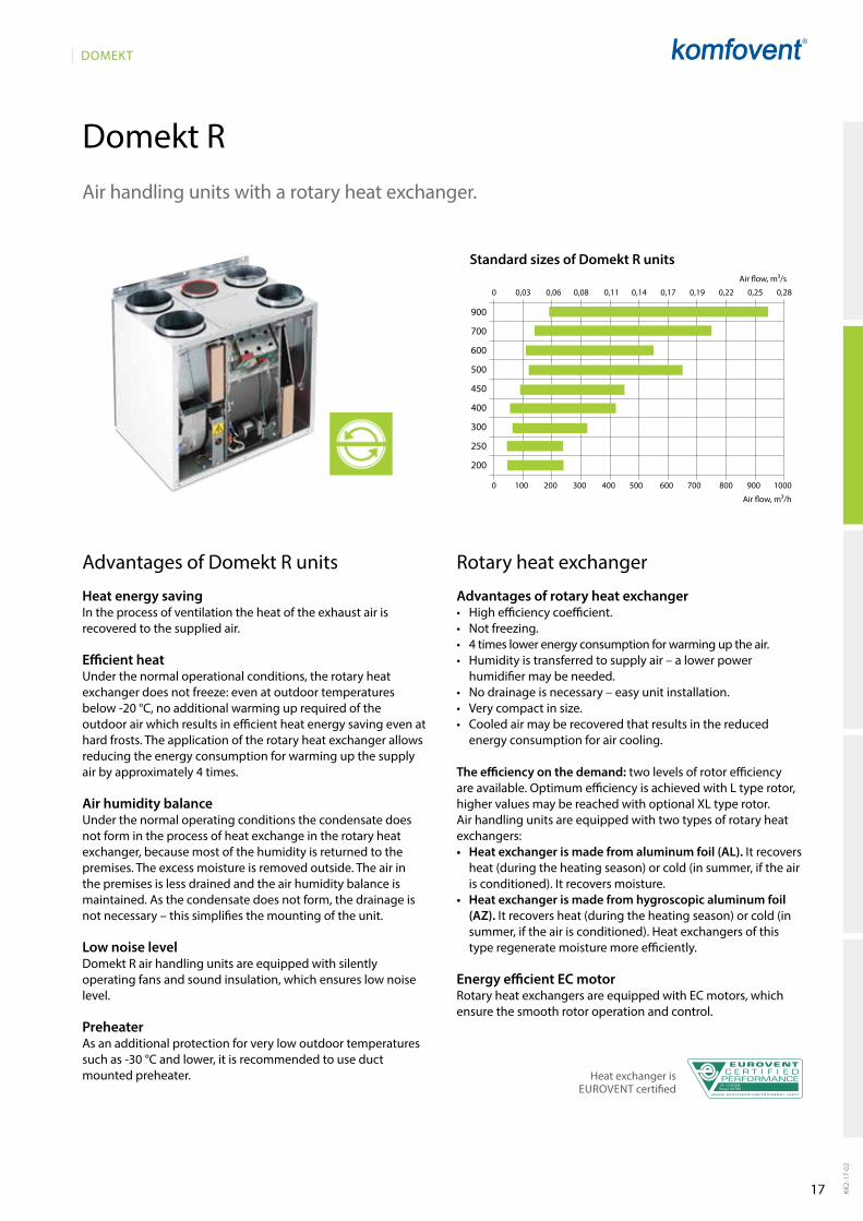
Air handling units with a rotary heat exchanger.
Advantages of Domekt R units
Heat energy saving In the process of ventilation the heat of the exhaust air is recovered to the supplied air.
Efficient heat Under the normal operational conditions, the rotary heat exchanger does not freeze: even at outdoor tempe ratures below -20 °C, no additional warming up required of the outdoor air which results in efficient heat energy saving even at hard frosts. The application of the rotary heat exchanger allows reducing the energy consumption for warming up the supply air by approximately 4 times.
Air humidity balanceUnder the normal operating conditions the condensate does not form in the process of heat exchange in the rotary heat exchanger, because most of the humidity is returned to the premises. The excess moisture is removed outside. The air in the premises is less drained and the air humidity balance is maintained. As the condensate does not form, the drainage is not necessary – this simplifies the mounting of the unit.
Low noise levelDomekt R air handling units are equipped with silently operating fans and sound insulation, which ensures low noise level.
PreheaterAs an additional protection for very low outdoor temperatures such as -30 °C and lower, it is recommended to use duct mounted preheater.
Rotary heat exchanger
Advantages of rotary heat exchanger• High efficiency coefficient.• Not freezing.• 4 times lower energy consumption for warming up the air.• Humidity is transferred to supply air – a lower power
humidifier may be needed.• No drainage is necessary – easy unit installation.• Very compact in size.• Cooled air may be recovered that results in the reduced
energy consumption for air cooling.
The efficiency on the demand: two levels of rotor efficiency are available. Optimum efficiency is achieved with l type rotor, higher values may be reached with optional Xl type rotor.Air handling units are equipped with two types of rotary heat exchangers:• Heat exchanger is made from aluminum foil (AL). It reco vers
heat (during the heating season) or cold (in summer, if the air is conditioned). It recovers moisture.
• Heat exchanger is made from hygroscopic aluminum foil (AZ). It recovers heat (during the heating season) or cold (in summer, if the air is conditioned). Heat exchan gers of this type regene rate moisture more efficiently.
Energy efficient EC motorRotary heat exchangers are equipped with EC motors, which ensure the smooth rotor ope ration and control.
Standard sizes of Domekt R units
Heat exchanger is EUROVENT certified No: 12.09.004
Range: ROTOR
Air flow, m³/h
Air flow, m³/s

18
DOMEKT
UAB AMALVA reserves the right to introduce the changes of parameters and sizes in the process of improvement of the air handling units.KK2-
17-0
2
� standard equipment� possible choice ordered separately* available only l wave height
Domekt R range
Duct connection
H – horizontal.V – vertical.U – universal, 14 installation options.F – false ceiling.
Heat exchanger
AZ – entalpic, sorption rotary heat exchanger coated with special 4Å coating. Wave hight of this heat exchanger is l.
Al – aluminum, condensing rotor. As a standard, units are equipped with l wave height of the rotors. In exceptional cases, when increased thermal efficiency is required, the units can be equipped with Xl wave.
Heater
HE – electric heater.
HW – water duct heater is installed on the duct and must be ordered separately. Heaters are mounted on the outside of the unit in any user-convenient place. 0...10 V heater control included in automatic control system.
HCW – heater-cooler one for both – heating and cooling. Ideal for buildings using geothermal energy.
Cooler
CW – designed for air cooling using cold water (water-glycol mixture), provides a higher comfort level in rooms.
CDX – designed for air cooling using direct expansion cooling unit, provides a higher comfort level in rooms.
Inspection side
See p. 132.
Control system
C6 Control features:• Temperature maintenance modes:
Supply air / Extract air / Room / Balance;• Air flow indication: m3/h; l/s;• Constant air volume control (CAV);• Variable air volume control (VAV)*;• Directly controlled volume (DCV);• External water coil control;• External DX unit control;• Weekly operation schedule;• Holidays planning;• Air quality control*;• Operation on demand*;• Cool recovery;• Temperature saving function;• Free cooling;• Ventilation control by external contacts;• Control via internet browser;• Control with smartphones;• Filter clogging indication;• Water mixing system warming-up;• Rotor warm-up and cleaning function;• Heat exchanger frost protection;• Heat exchanger failure indication;• Water heater frost protection;• Electric heater overheat protection;• low air flow indication;• Emergency shut down in case of fire;• Emergency shut down when temperature
reaches critical limits;• Intelligent self-diagnostic;• Indication of the heat exchanger thermal efficiency (%);• Indication of heat exchanger energy recovery (kW);• Energy consumption counters for heater and whole unit (kWh);• Indication of the whole unit power consumption (kW);• Specific power (SPI) indication;• Unit operation parameters history storage and analysis;• Possibility to choose desired control panel.
* these functions require additional accessories.
More information about C4 on p. 14.More information about C5 on p. 10.
Unit size
Heat exchanger Supply/exhaust air filter class
Heater Cooler Inspection sideControl system / panel
Type Wave height C4 C5 C6
Al AZ* l Xl M5 F7 HE HW HCW CW CDX R1 R2 l1 l2 C4.1 C5.1 C6.1 C6.2
Domekt R 200 V � � � � � � � � �
Domekt R 250 F � � � � � � � � � � �
Domekt R 300 V � � � � � � � � � � �
Domekt R 400 V � � � � � � � � � � �
Domekt R 400 H � � � � � � � � � � �
Domekt R 400 F � � � � � � � � � � �
Domekt R 450 V � � � � � � � � � � �
Domekt R 500 V/H � � � � � � � � � � �
Domekt R 600 U � � � � � � � � � � �
Domekt R 600 H � � � � � � � � � � �
Domekt R 700 V � � � � � � � � � � �
Domekt R 700 H � � � � � � � � � � �
Domekt R 700 F � � � � � � � � � � �
Domekt R 900 U � � � � � � � � � � �
Domekt R 900 H/V � � � � � � � � � � �

19
DOMEKT
A
258 m³/h43
Domekt R 200 V
258
25
42
1~ 230
HE 4,7
82
0,05
50
0,35
285×130×46-M5
27
66
0,8 / 12,3
C4.1
300
300
600
660
625
320
136
92
∅125 (5×)
160
A
B C E
D
F
AB C E D
F
81 145 148 145
D AC E B
C4.1
11,6 13,5 14,6 15,8 16,953
66
53
66
43
33
0 0,01 0,02 0,03 0,04 0,05 0,06 0,07 0,08 0,09
0 50 100 150 200 250 300 350
350
300
250
200
150
100
50
0
SPI 0,3
SPI 0,4
SPI 0,5
SPI 0,6KK
2-17
-02
UAB AMALVA reserves the right to introduce the changes of parameters and sizes in the process of improvement of the air handling units. If data of performance do not correspond to data in the selection software, please refer to data shown in software.
The
phot
o is
inte
nded
for i
nfor
mat
iona
l pur
pose
s on
ly, e
xact
det
ails
may
var
y.
Acoustic dataA-weighted sound power level LwA, dB(A)at reference flow rate
Supply inlet
Supply outlet
Exhaust inlet
Exhaust outlet
Casing
A-weighted sound pressure level LPA, dB(A) 10 m² normally isolated room, distance from casing – 3 m.
Surroundings
Maximal air flow, m³/h
Panel thickness, mm
Unit weight, kg
Supply voltage, V
Maximal operating current, A
Thermal efficiency of heat recovery, %
Reference flow rate, m³/s
Reference pressure difference, Pa
SPI, W/(m³/h)
Filters dimensions B×H×L, mm
Electric power input of the fan drive at reference flow rate, W
Electric power input of the fan drive at maximum flow rate, W
Electric air heater capacity, kW / ∆t, °C
Control panel
Maintenance space, mm
Stat
ic p
ress
ure
(Pa)
Air flow rate (m3/s)
Air flow rate (m3/h)
PerformanceUnit with standard equipment
Temperature efficiencyWinter Summer
Outside temperature, °C -23 -15 -10 -5 0 25 30 35
After heat exchanger*, °C
* indoor +22°C, 20 % RH
Closing damper
SilencerA/D
B/C
Water heater
PPU
2-way valve (water heater)
Air heater-cooler
2-way valve (water cooler)
A outdoor intakeB supply airC extract indoorD exhaust airE additional extraction connection
(by-pass – extraction without heat recovery)
F kitchen hood connection (by-pass – extraction without heat recovery)
Shown as right (R1)
Shown as left (L1)
Accessories
Closing damper AgUJ-M-125+lF230/lM230
SilencerA/D AgS-125-50-600-M
B/C AgS-125-50-900-M
Water heater DH-125
PPU PPU-HW-3R-15-0,4-W1
2-way valve (water heater) VVP47.10-0,4
Water cooler DHCW-125
2-way valve (water cooler) VVP47.10-1,6
Kitchen hood KH
Decorative panel DP
Air distribution box OSD-200 VE-125
Outdoor grill lD-125
20
DOMEKT
∅160 (4×)
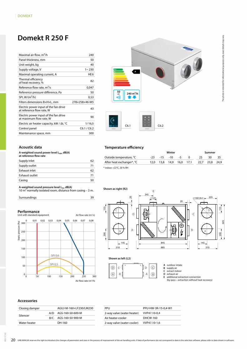
Domekt R 250 F
62
71
62
71
50
39
240
50
40
1~ 230
HE 6
82
0,047
50
0,53
278×258×46-M5
43
90
1/ 16,5
C6.1 / C6.2
300
A
240 m³/h50
C6.1 C6.2
0 0,01 0,02 0,03 0,04 0,05 0,06 0,07 0,08
B
D
A
C
B
D
A
C
E
20 205∅125245
20
145 145845
310 310885
155
200
200
155
605
D
A
C
B
DC
AB
12,0 13,8 14,9 16,0 17,1 22,7 23,8 24,9
AgUJ-M-160+lF230/lM230
AgS-160-50-600-M
AgS-160-50-900-M
DH-160
PPU-HW-3R-15-0,4-W1
VVP47.10-0,4
DHCW-160
VVP47.10-1,6
SPI 0,5
SPI 0,6
0 50 100 150 200 250 300
300
250
200
150
100
50
0
KK2-
17-0
2
The
phot
o is
inte
nded
for i
nfor
mat
iona
l pur
pose
s on
ly, e
xact
det
ails
may
var
y.
Acoustic dataA-weighted sound power level LwA, dB(A)at reference flow rate
Supply inlet
Supply outlet
Exhaust inlet
Exhaust outlet
Casing
A-weighted sound pressure level LPA, dB(A) 10 m² normally isolated room, distance from casing – 3 m.
Surroundings
Maximal air flow, m³/h
Panel thickness, mm
Unit weight, kg
Supply voltage, V
Maximal operating current, A
Thermal efficiency of heat recovery, %
Reference flow rate, m³/s
Reference pressure difference, Pa
SPI, W/(m³/h)
Filters dimensions B×H×L, mm
Electric power input of the fan drive at reference flow rate, W
Electric power input of the fan drive at maximum flow rate, W
Electric air heater capacity, kW / ∆t, °C
Control panel
Maintenance space, mm
Stat
ic p
ress
ure
(Pa)
Air flow rate (m3/s)
Air flow rate (m3/h)
PerformanceUnit with standard equipment
UAB AMALVA reserves the right to introduce the changes of parameters and sizes in the process of improvement of the air handling units. If data of performance do not correspond to data in the selection software, please refer to data shown in software.
Temperature efficiencywinter Summer
Outside temperature, °C -23 -15 -10 -5 0 25 30 35
After heat exchanger*, °C
* indoor +22°C, 20 % RH
Accessories
Closing damper
SilencerA/D
B/C
Water heater
PPU
2-way valve (water heater)
Air heater-cooler
2-way valve (water cooler)
A outdoor intakeB supply airC extract indoorD exhaust airE additional extraction connection
(by-pass – extraction without heat recovery)
Shown as right (R2)
Shown as left (L2)
21
DOMEKT
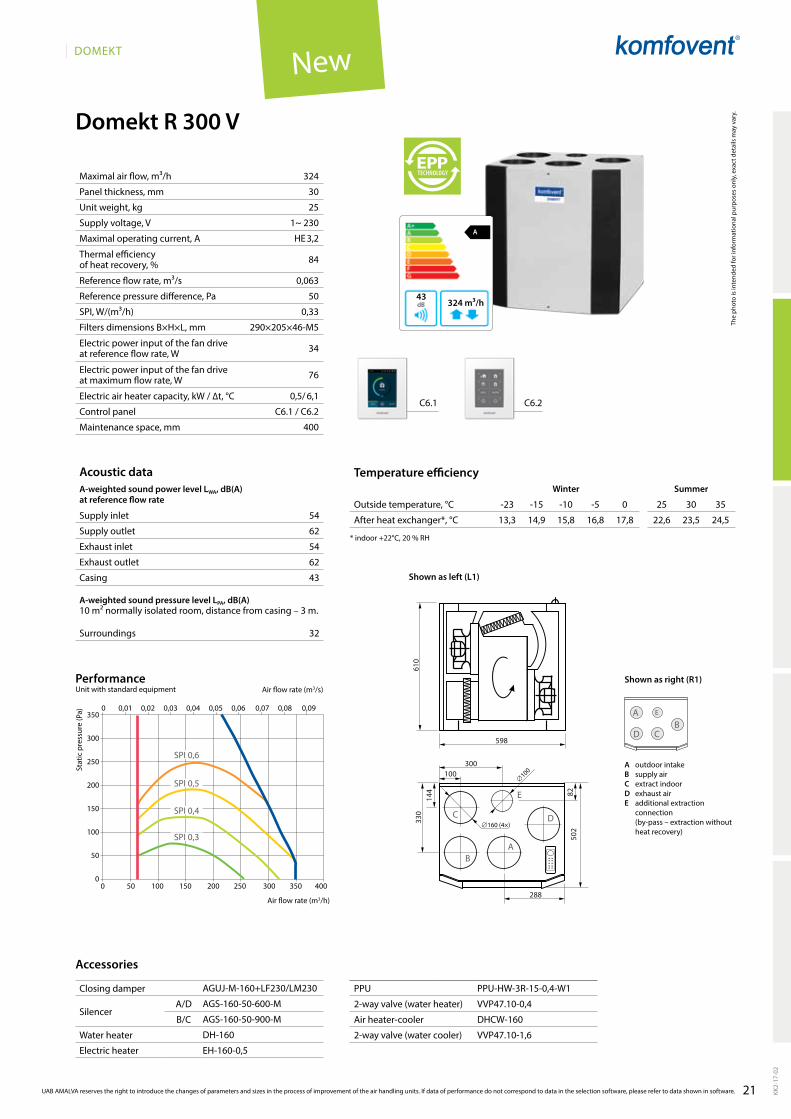
Domekt R 300 V
54
62
54
62
43
32
324
30
25
1~ 230
HE 3,2
84
0,063
50
0,33
290×205×46-M5
34
76
0,5/ 6,1
C6.1 / C6.2
400
C6.1 C6.2
13,3 14,9 15,8 16,8 17,8 22,6 23,5 24,5
0 0,01 0,02 0,03 0,04 0,05 0,06 0,07 0,08 0,09
0 50 100 150 200 250 300 350 400
350
300
250
200
150
100
50
0
SPI 0,3
SPI 0,4
SPI 0,5
SPI 0,6
A
324 m³/h43
610
598
144 82
330
502
С D
BA
E
288
∅160 (4×)
∅100100300
D
A
CB
E
KK2-
17-0
2
UAB AMALVA reserves the right to introduce the changes of parameters and sizes in the process of improvement of the air handling units. If data of performance do not correspond to data in the selection software, please refer to data shown in software.
The
phot
o is
inte
nded
for i
nfor
mat
iona
l pur
pose
s on
ly, e
xact
det
ails
may
var
y.
Acoustic dataA-weighted sound power level LwA, dB(A)at reference flow rate
Supply inlet
Supply outlet
Exhaust inlet
Exhaust outlet
Casing
A-weighted sound pressure level LPA, dB(A) 10 m² normally isolated room, distance from casing – 3 m.
Surroundings
Maximal air flow, m³/h
Panel thickness, mm
Unit weight, kg
Supply voltage, V
Maximal operating current, A
Thermal efficiency of heat recovery, %
Reference flow rate, m³/s
Reference pressure difference, Pa
SPI, W/(m³/h)
Filters dimensions B×H×L, mm
Electric power input of the fan drive at reference flow rate, W
Electric power input of the fan drive at maximum flow rate, W
Electric air heater capacity, kW / ∆t, °C
Control panel
Maintenance space, mm
Stat
ic p
ress
ure
(Pa)
Air flow rate (m3/s)
Air flow rate (m3/h)
PerformanceUnit with standard equipment
Temperature efficiencyWinter Summer
Outside temperature, °C -23 -15 -10 -5 0 25 30 35
After heat exchanger*, °C
* indoor +22°C, 20 % RH
Accessories
Closing damper
SilencerA/D
B/C
Water heater
PPU
2-way valve (water heater)
Air heater-cooler
2-way valve (water cooler)
A outdoor intakeB supply airC extract indoorD exhaust airE additional extraction
connection (by-pass – extraction without heat recovery)
Shown as right (R1)
Shown as left (L1)
AgUJ-M-160+lF230/lM230
AgS-160-50-600-M
AgS-160-50-900-M
DH-160
Electric heater EH-160-0,5
PPU-HW-3R-15-0,4-W1
VVP47.10-0,4
DHCW-160
VVP47.10-1,6
New

22
DOMEKT
Domekt R 400 V
A+
287 m³/h39
300
600
DAECB
C
B
DE
A
495
565
547
420 90
231
131
∅125
∅160 (4×)
52
65
52
65
39
29
D
A
C
BE
C6.1 C6.2
0 50 100 150 200 250 300 350
400
350
300
250
200
150
100
50
0
0 0,01 0,02 0,03 0,04 0,05 0,06 0,07 0,08 0,09
SPI 0,6
SPI 0,3
SPI 0,4
SPI 0,5
15,2 16,4 17,2 17,9 18,7 22,5 23,2 24,0
AgUJ-M-160+lF230/lM230
AgS-160-50-600-M
AgS-160-50-900-M
DH-160
PPU-HW-3R-15-0,4-W1
VVP47.10-0,4
DCW-0,4-3 / DHCW-160
VVP47.10-1,6
DCF-0,4-3
287
25
64
1~ 230
HE 5,5
87
0,056
50
0,27
450×210×46-M5
23
71
1 / 13,8
C6.1 / C6.2
450
KK2-
17-0
2
The
phot
o is
inte
nded
for i
nfor
mat
iona
l pur
pose
s on
ly, e
xact
det
ails
may
var
y.
Acoustic dataA-weighted sound power level LwA, dB(A)at reference flow rate
Supply inlet
Supply outlet
Exhaust inlet
Exhaust outlet
Casing
A-weighted sound pressure level LPA, dB(A) 10 m² normally isolated room, distance from casing – 3 m.
Surroundings
Maximal air flow, m³/h
Panel thickness, mm
Unit weight, kg
Supply voltage, V
Maximal operating current, A
Thermal efficiency of heat recovery, %
Reference flow rate, m³/s
Reference pressure difference, Pa
SPI, W/(m³/h)
Filters dimensions B×H×L, mm
Electric power input of the fan drive at reference flow rate, W
Electric power input of the fan drive at maximum flow rate, W
Electric air heater capacity, kW / ∆t, °C
Control panel
Maintenance space, mm
Stat
ic p
ress
ure
(Pa)
Air flow rate (m3/s)
Air flow rate (m3/h)
PerformanceUnit with standard equipment
UAB AMALVA reserves the right to introduce the changes of parameters and sizes in the process of improvement of the air handling units. If data of performance do not correspond to data in the selection software, please refer to data shown in software.
Temperature efficiencywinter Summer
Outside temperature, °C -23 -15 -10 -5 0 25 30 35
After heat exchanger*, °C
* indoor +22°C, 20 % RH
Accessories
Closing damper
SilencerA/D
B/C
Water heater
PPU
2-way valve (water heater)
Air heater-cooler
2-way valve (water cooler)
DX cooler
Cooling unit
A outdoor intakeB supply airC extract indoorD exhaust airE additional extraction
connection (by-pass – extraction without heat recovery)
Shown as right (R1)
Shown as left (L1)
23
DOMEKT
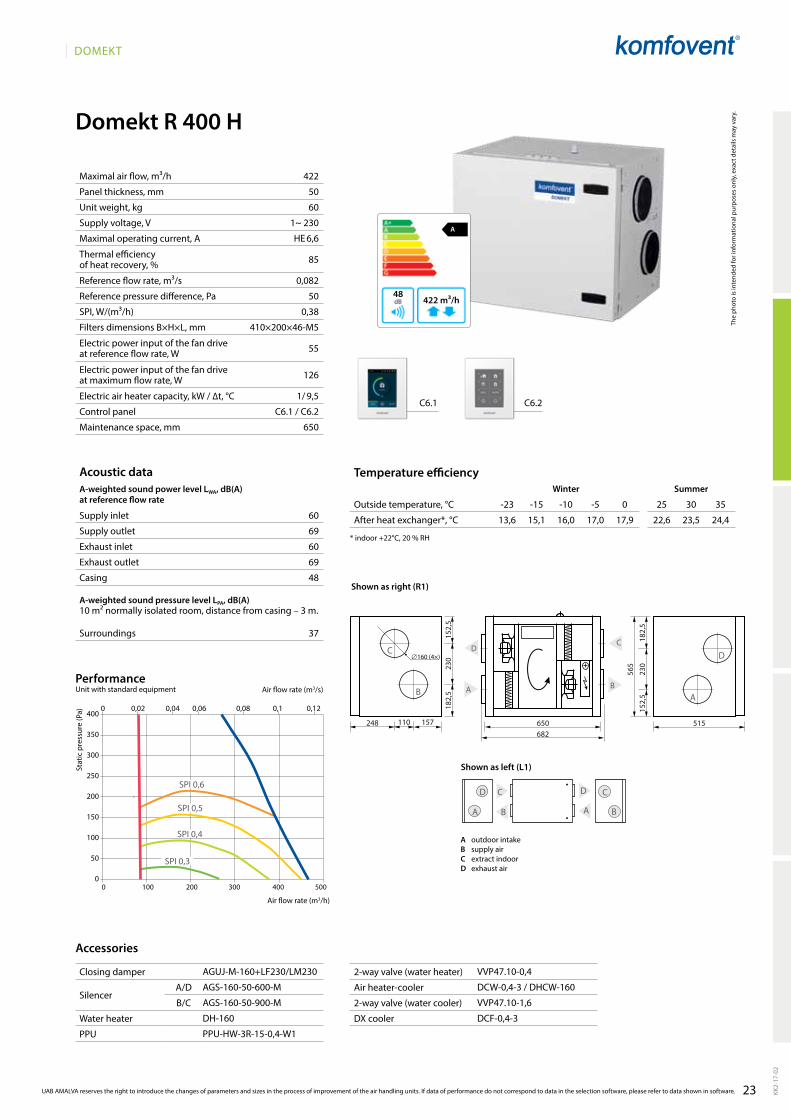
Domekt R 400 H
A
422 m³/h48
422
50
60
1~ 230
HE 6,6
85
0,082
50
0,38
410×200×46-M5
55
126
1/ 9,5
C6.1 / C6.2
650
60
69
60
69
48
37
0 100 200 300 400 500
400
350
300
250
200
150
100
50
0
SPI 0,3
SPI 0,4
SPI 0,5
SPI 0,6
0 0,02 0,04 0,06 0,08 0,1 0,12
13,6 15,1 16,0 17,0 17,9 22,6 23,5 24,4
C6.1 C6.2
152,
523
018
2,5
152,
523
0
565
182,
5
157110248 650
С D
B A
DC
A B
682515
∅160 (4×)
D
A
C
B
DC
AB
AgUJ-M-160+lF230/lM230
AgS-160-50-600-M
AgS-160-50-900-M
DH-160
PPU-HW-3R-15-0,4-W1
VVP47.10-0,4
DCW-0,4-3 / DHCW-160
VVP47.10-1,6
DCF-0,4-3
KK2-
17-0
2
UAB AMALVA reserves the right to introduce the changes of parameters and sizes in the process of improvement of the air handling units. If data of performance do not correspond to data in the selection software, please refer to data shown in software.
The
phot
o is
inte
nded
for i
nfor
mat
iona
l pur
pose
s on
ly, e
xact
det
ails
may
var
y.
Acoustic dataA-weighted sound power level LwA, dB(A)at reference flow rate
Supply inlet
Supply outlet
Exhaust inlet
Exhaust outlet
Casing
A-weighted sound pressure level LPA, dB(A) 10 m² normally isolated room, distance from casing – 3 m.
Surroundings
Maximal air flow, m³/h
Panel thickness, mm
Unit weight, kg
Supply voltage, V
Maximal operating current, A
Thermal efficiency of heat recovery, %
Reference flow rate, m³/s
Reference pressure difference, Pa
SPI, W/(m³/h)
Filters dimensions B×H×L, mm
Electric power input of the fan drive at reference flow rate, W
Electric power input of the fan drive at maximum flow rate, W
Electric air heater capacity, kW / ∆t, °C
Control panel
Maintenance space, mm
Stat
ic p
ress
ure
(Pa)
Air flow rate (m3/s)
Air flow rate (m3/h)
PerformanceUnit with standard equipment
Temperature efficiencyWinter Summer
Outside temperature, °C -23 -15 -10 -5 0 25 30 35
After heat exchanger*, °C
* indoor +22°C, 20 % RH
Accessories
Closing damper
SilencerA/D
B/C
Water heater
PPU
2-way valve (water heater)
Air heater-cooler
2-way valve (water cooler)
DX cooler
Cooling unit
Shown as right (R1)
Shown as left (L1)
A outdoor intakeB supply airC extract indoorD exhaust air

24
DOMEKT
Domekt R 400 F
472
50
67
1~ 230
HE 7,2
82
0,092
50
0,44
278×258×46-M5
72
165
1 / 8,4
C6.1 / C6.2
300
63
72
63
72
52
41
A
472 m³/h52
D
A
B
C
D
C A
B
C6.1 C6.2
AGUJ-M-200+LF230/LM230
AGS-200-50-600-M
AGS-200-50-900-M
DH-200
PPU-HW-3R-15-0,63-W1
VVP47.10-0,63
DCW-0,4-3 / DHCW-200
VVP47.10-2,5
DCF-0,4-3
11,8 13,6 14,8 15,9 17,0 22,7 23,8 24,9
SPI 0,6
SPI 0,3
0 0,02 0,04 0,06 0,08 0,1 0,12 0,14
0 100 200 300 400 500 600
300
250
200
150
100
50
0
SPI 0,4
SPI 0,5
B D
A
C
B D
A C
E
20
387
20130
1451170330
1202
225
310
310
225
700∅200 (4×)
∅125
KK2-
17-0
2
The
phot
o is
inte
nded
for i
nfor
mat
iona
l pur
pose
s on
ly, e
xact
det
ails
may
var
y.
Acoustic dataA-weighted sound power level LwA, dB(A)at reference flow rate
Supply inlet
Supply outlet
Exhaust inlet
Exhaust outlet
Casing
A-weighted sound pressure level LPA, dB(A) 10 m² normally isolated room, distance from casing – 3 m.
Surroundings
Maximal air flow, m³/h
Panel thickness, mm
Unit weight, kg
Supply voltage, V
Maximal operating current, A
Thermal efficiency of heat recovery, %
Reference flow rate, m³/s
Reference pressure difference, Pa
SPI, W/(m³/h)
Filters dimensions B×H×L, mm
Electric power input of the fan drive at reference flow rate, W
Electric power input of the fan drive at maximum flow rate, W
Electric air heater capacity, kW / ∆t, °C
Control panel
Maintenance space, mm
Stat
ic p
ress
ure
(Pa)
Air flow rate (m3/s)
Air flow rate (m3/h)
PerformanceUnit with standard equipment
UAB AMALVA reserves the right to introduce the changes of parameters and sizes in the process of improvement of the air handling units. If data of performance do not correspond to data in the selection software, please refer to data shown in software.
Temperature efficiencywinter Summer
Outside temperature, °C -23 -15 -10 -5 0 25 30 35
After heat exchanger*, °C
* indoor +22°C, 20 % RH
Accessories
A outdoor intakeB supply airC extract indoorD exhaust airE additional extraction connection
(by-pass – extraction without heat recovery)
Shown as right (R1)
Shown as left (L1)
Closing damper
SilencerA/D
B/C
Water heater
PPU
2-way valve (water heater)
Air heater-cooler
2-way valve (water cooler)
DX cooler

25
DOMEKT
Domekt R 450 V
A
472 m³/h39
472
50
71
1~ 230
HE 7,1
85
0,092
50
0,44
470×240×46-M5
72
170
1 / 8,4
C6.1 / C6.2
500
58
72
58
72
39
29
630
610
D AECB
C
B
DE
A
∅125
∅160 (4 ×)
340110
535
150
255
460
680
0 0,02 0,04 0,06 0,08 0,1 0,12 0,14 0,16
0 100 200 300 400 500 600
400
350
300
250
200
150
100
50
0
SPI 0,3
SPI 0,4
SPI 0,5
SPI 0,6
C6.1 C6.2
14,3 15,7 16,5 17,4 18,2 22,5 23,4 24,2
AgUJ-M-160+lF230/lM230
AgS-160-50-600-M
AgS-160-50-900-M
DH-160
PPU-HW-3R-15-0,4-W1
VVP47.10-0,4
DCW-0,5-3 / DHCW-160
VVP47.10-1,6
DCF-0,5-3
D
A
C
BE
KK2-
17-0
2
UAB AMALVA reserves the right to introduce the changes of parameters and sizes in the process of improvement of the air handling units. If data of performance do not correspond to data in the selection software, please refer to data shown in software.
The
phot
o is
inte
nded
for i
nfor
mat
iona
l pur
pose
s on
ly, e
xact
det
ails
may
var
y.
Acoustic dataA-weighted sound power level LwA, dB(A)at reference flow rate
Supply inlet
Supply outlet
Exhaust inlet
Exhaust outlet
Casing
A-weighted sound pressure level LPA, dB(A) 10 m² normally isolated room, distance from casing – 3 m.
Surroundings
Maximal air flow, m³/h
Panel thickness, mm
Unit weight, kg
Supply voltage, V
Maximal operating current, A
Thermal efficiency of heat recovery, %
Reference flow rate, m³/s
Reference pressure difference, Pa
SPI, W/(m³/h)
Filters dimensions B×H×L, mm
Electric power input of the fan drive at reference flow rate, W
Electric power input of the fan drive at maximum flow rate, W
Electric air heater capacity, kW / ∆t, °C
Control panel
Maintenance space, mm
Stat
ic p
ress
ure
(Pa)
Air flow rate (m3/s)
Air flow rate (m3/h)
PerformanceUnit with standard equipment
Temperature efficiencyWinter Summer
Outside temperature, °C -23 -15 -10 -5 0 25 30 35
After heat exchanger*, °C
* indoor +22°C, 20 % RH
Accessories
Closing damper
SilencerA/D
B/C
Water heater
PPU
2-way valve (water heater)
Air heater-cooler
2-way valve (water cooler)
DX cooler
Cooling unit
A outdoor intakeB supply airC extract indoorD exhaust airE additional extraction
connection (by-pass – extraction without heat recovery)
Shown as right (R1)
Shown as left (L1)

26
DOMEKT
Domekt R 500 V
A+
630 m³/h42
630
50
140
1~ 230
HE 7,2
85
0,12
50
0,27
540×260×46-M5
57
125
1 / 6,3
C6.1 / C6.2
1050
54
62
54
62
42
31
966
950
186
22916
664
5
∅250 (4×)
∅125228
1070
190 190228
D
AС
B
D AC EB
500
400
300
200
100
0
0 0,02 0,04 0,06 0,08 0,1 0,12 0,14 0,16 0,18
0 100 200 300 400 500 600 700
SPI 0,3
SPI 0,4
SPI 0,5
SPI 0,6
C6.1 C6.2
13,9 15,4 16,9 18,0 14,7 22,5 23,4 24,2
AgUJ-M-250+lF230/lM230
AgS-250-50-600-M
AgS-250-50-900-M
DH-250
PPU-HW-3R-15-0,63-W1
VVP47.10-0,63
DCW-0,5-3 / DHCW-250
VVP47.10-2,5
DCF-0,5-3
D
A
B
C
E
E
KK2-
17-0
2
The
phot
o is
inte
nded
for i
nfor
mat
iona
l pur
pose
s on
ly, e
xact
det
ails
may
var
y.
Acoustic dataA-weighted sound power level LwA, dB(A)at reference flow rate
Supply inlet
Supply outlet
Exhaust inlet
Exhaust outlet
Casing
A-weighted sound pressure level LPA, dB(A) 10 m² normally isolated room, distance from casing – 3 m.
Surroundings
Maximal air flow, m³/h
Panel thickness, mm
Unit weight, kg
Supply voltage, V
Maximal operating current, A
Thermal efficiency of heat recovery, %
Reference flow rate, m³/s
Reference pressure difference, Pa
SPI, W/(m³/h)
Filters dimensions B×H×L, mm
Electric power input of the fan drive at reference flow rate, W
Electric power input of the fan drive at maximum flow rate, W
Electric air heater capacity, kW / ∆t, °C
Control panel
Maintenance space, mm
Stat
ic p
ress
ure
(Pa)
Air flow rate (m3/s)
Air flow rate (m3/h)
PerformanceUnit with standard equipment
UAB AMALVA reserves the right to introduce the changes of parameters and sizes in the process of improvement of the air handling units. If data of performance do not correspond to data in the selection software, please refer to data shown in software.
Temperature efficiencywinter Summer
Outside temperature, °C -23 -15 -10 -5 0 25 30 35
After heat exchanger*, °C
* indoor +22°C, 20 % RH
Accessories
Closing damper
SilencerA/D
B/C
Water heater
PPU
2-way valve (water heater)
Air heater-cooler
2-way valve (water cooler)
DX cooler
Cooling unit
Shown as left (L1)
Shown as right (R1)
A outdoor intakeB supply airC extract indoorD exhaust airE additional extraction connection
(by-pass – extraction without heat recovery)

27
DOMEKT
Domekt R 500 H
A
630 m³/h46
58
67
58
67
46
35
630
50
90
1~ 230
HE 7,2
85
0,122
50
0,31
540×260×46-M5
67
155
1 / 6,3
C6.1 / C6.2
950
500
400
300
200
100
0
0 0,02 0,04 0,06 0,08 0,1 0,12 0,14 0,16 0,18
0 100 200 300 400 500 600 700
SPI 0,3
SPI 0,4
SPI 0,5
SPI 0,6
C6.1 C6.2
E
465
150
∅125
D C
A B
257 930963
402
402 257
647
198
198
198
198
700
D
A
E
С
B
∅200 (4×)
D
A
C
B
DC
AB
14,3 15,6 16,5 17,4 18,2 22,5 23,4 24,2
AgUJ-M-200+lF230/lM230
AgS-200-50-600-M
AgS-200-50-900-M
DH-200
PPU-HW-3R-15-0,63-W1
VVP47.10-0,63
DCW-0,5-3 / DHCW-200
VVP47.10-2,5
DCF-0,5-3
KK2-
17-0
2
UAB AMALVA reserves the right to introduce the changes of parameters and sizes in the process of improvement of the air handling units. If data of performance do not correspond to data in the selection software, please refer to data shown in software.
The
phot
o is
inte
nded
for i
nfor
mat
iona
l pur
pose
s on
ly, e
xact
det
ails
may
var
y.
Acoustic dataA-weighted sound power level LwA, dB(A)at reference flow rate
Supply inlet
Supply outlet
Exhaust inlet
Exhaust outlet
Casing
A-weighted sound pressure level LPA, dB(A) 10 m² normally isolated room, distance from casing – 3 m.
Surroundings
Maximal air flow, m³/h
Panel thickness, mm
Unit weight, kg
Supply voltage, V
Maximal operating current, A
Thermal efficiency of heat recovery, %
Reference flow rate, m³/s
Reference pressure difference, Pa
SPI, W/(m³/h)
Filters dimensions B×H×L, mm
Electric power input of the fan drive at reference flow rate, W
Electric power input of the fan drive at maximum flow rate, W
Electric air heater capacity, kW / ∆t, °C
Control panel
Maintenance space, mm
Stat
ic p
ress
ure
(Pa)
Air flow rate (m3/s)
Air flow rate (m3/h)
PerformanceUnit with standard equipment
Temperature efficiencyWinter Summer
Outside temperature, °C -23 -15 -10 -5 0 25 30 35
After heat exchanger*, °C
* indoor +22°C, 20 % RH
Accessories
Closing damper
SilencerA/D
B/C
Water heater
PPU
2-way valve (water heater)
Air heater-cooler
2-way valve (water cooler)
DX cooler
Cooling unit
A outdoor intakeB supply airC extract indoorD exhaust airE additional extraction connection
(by-pass – extraction without heat recovery)
Shown as right (R1)
Shown as left (L1)
28
DOMEKT
C5.1
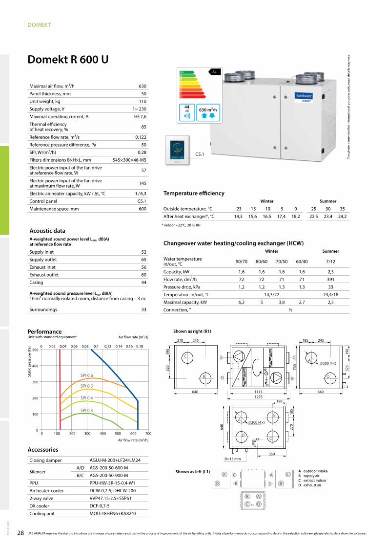
Domekt R 600 UA+
630 m³/h44
630
50
110
1~ 230
HE 7,6
85
0,122
50
0,28
545×300×46-M5
57
145
1 / 6,3
C5.1
600
52
65
56
60
44
33
14,3 15,6 16,5 17,4 18,2 22,5 23,4 24,2
AgUJ-M-200+lF24/lM24
AgS-200-50-600-M
AgS-200-50-900-M
PPU-HW-3R-15-0,4-W1
DCW-0,7-5; DHCW-200
VVP47.15-2,5+SSP61
DCF-0,7-5
MOU-18HFN6+KA8243
1,6 1,6 1,6 1,6 2,3
72 72 71 71 391
1,2 1,2 1,3 1,3 33
14,3/22 23,4/18
6,2 5 3,8 2,7 2,3
½
500
400
300
200
100
0
0 0,02 0,04 0,06 0,08 0,1 0,12 0,14 0,16 0,18
0 100 200 300 400 500 600 700
SPI 0,3
SPI 0,4
SPI 0,5
SPI 0,6
KK2-
17-0
2
UAB AMALVA reserves the right to introduce the changes of parameters and sizes in the process of improvement of the air handling units. If data of performance do not correspond to data in the selection software, please refer to data shown in software.
Closing damper
SilencerA/D
B/C
PPU
Air heater-cooler
2-way valve
DX cooler
Cooling unit
The
phot
o is
inte
nded
for i
nfor
mat
iona
l pur
pose
s on
ly, e
xact
det
ails
may
var
y.
Acoustic dataA-weighted sound power level LwA, dB(A)at reference flow rate
Supply inlet
Supply outlet
Exhaust inlet
Exhaust outlet
Casing
A-weighted sound pressure level LPA, dB(A) 10 m² normally isolated room, distance from casing – 3 m.
Surroundings
Maximal air flow, m³/h
Panel thickness, mm
Unit weight, kg
Supply voltage, V
Maximal operating current, A
Thermal efficiency of heat recovery, %
Reference flow rate, m³/s
Reference pressure difference, Pa
SPI, W/(m³/h)
Filters dimensions B×H×L, mm
Electric power input of the fan drive at reference flow rate, W
Electric power input of the fan drive at maximum flow rate, W
Electric air heater capacity, kW / ∆t, °C
Control panel
Maintenance space, mm
Stat
ic p
ress
ure
(Pa)
Air flow rate (m3/s)
Air flow rate (m3/h)
PerformanceUnit with standard equipment
Temperature efficiencywinter Summer
Outside temperature, °C -23 -15 -10 -5 0 25 30 35
After heat exchanger*, °C
* indoor +22°C, 20 % RH
Accessories
Changeover water heating/cooling exchanger (HCw)winter Summer
Water temperature in/out, °C 90/70 80/60 70/50 60/40 7/12
Capacity, kW
Flow rate, dm³/h
Pressure drop, kPa
Temperature in/out, °C
Maximal capacity, kW
Connection, ”
185210 245245
640640 11151275
700
640
190
190
320
320
С
B D
A
∅200 (4×)
∅200 (4×)
350
190
100
185
270
C
B
D
A
D=15 mm
C
A
D
B
B
D
A
C
C
C
A
A
B
B
D
D
Shown as right (R1)
Shown as left (L1) A outdoor intakeB supply airC extract indoorD exhaust air
29
DOMEKT
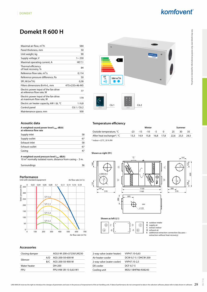
Domekt R 600 H
58
67
58
67
47
36
584
50
90
1~ 230
HE 7,1
84
0,114
50
0,38
475×235×46-M5
77
179
1 / 6,8
C6.1 / C6.2
500
A
584 m³/h47
0 100 200 300 400 500 600 700
350
300
250
200
150
100
50
0
0 0,02 0,04 0,06 0,08 0,1 0,12 0,14 0,16 0,18
SPI 0,3
SPI 0,4
SPI 0,5
SPI 0,6
C6.1 C6.2
D
A
C
B
DC
AB
B
D
A
C
B
D
A
C
197
197 2851130570 5701160
305
168
122
168
122
600
286
∅200 (4×)
∅125
E
13,3 14,9 15,8 16,8 17,8 22,6 23,5 24,5
AgUJ-M-200+lF230/lM230
AgS-200-50-600-M
AgS-200-50-900-M
DH-200
PPU-HW-3R-15-0,63-W1
VVP47.10-0,63
DCW-0,7-5 / DHCW-200
VVP47.10-2,5
DCF-0,7-5
MOU-18HFN6-KA8243
KK2-
17-0
2
UAB AMALVA reserves the right to introduce the changes of parameters and sizes in the process of improvement of the air handling units. If data of performance do not correspond to data in the selection software, please refer to data shown in software.
The
phot
o is
inte
nded
for i
nfor
mat
iona
l pur
pose
s on
ly, e
xact
det
ails
may
var
y.
Acoustic dataA-weighted sound power level LwA, dB(A)at reference flow rate
Supply inlet
Supply outlet
Exhaust inlet
Exhaust outlet
Casing
A-weighted sound pressure level LPA, dB(A) 10 m² normally isolated room, distance from casing – 3 m.
Surroundings
Maximal air flow, m³/h
Panel thickness, mm
Unit weight, kg
Supply voltage, V
Maximal operating current, A
Thermal efficiency of heat recovery, %
Reference flow rate, m³/s
Reference pressure difference, Pa
SPI, W/(m³/h)
Filters dimensions B×H×L, mm
Electric power input of the fan drive at reference flow rate, W
Electric power input of the fan drive at maximum flow rate, W
Electric air heater capacity, kW / ∆t, °C
Control panel
Maintenance space, mm
Stat
ic p
ress
ure
(Pa)
Air flow rate (m3/s)
Air flow rate (m3/h)
Temperature efficiencyWinter Summer
Outside temperature, °C -23 -15 -10 -5 0 25 30 35
After heat exchanger*, °C
* indoor +22°C, 20 % RH
Accessories
Closing damper
SilencerA/D
B/C
Water heater
PPU
2-way valve (water heater)
Air heater-cooler
2-way valve (water cooler)
DX cooler
Cooling unit
PerformanceUnit with standard equipment
A outdoor intakeB supply airC extract indoorD exhaust airE additional extraction connection (by-pass –
extraction without heat recovery)
Shown as right (R1)
Shown as left (L1)
30
DOMEKT
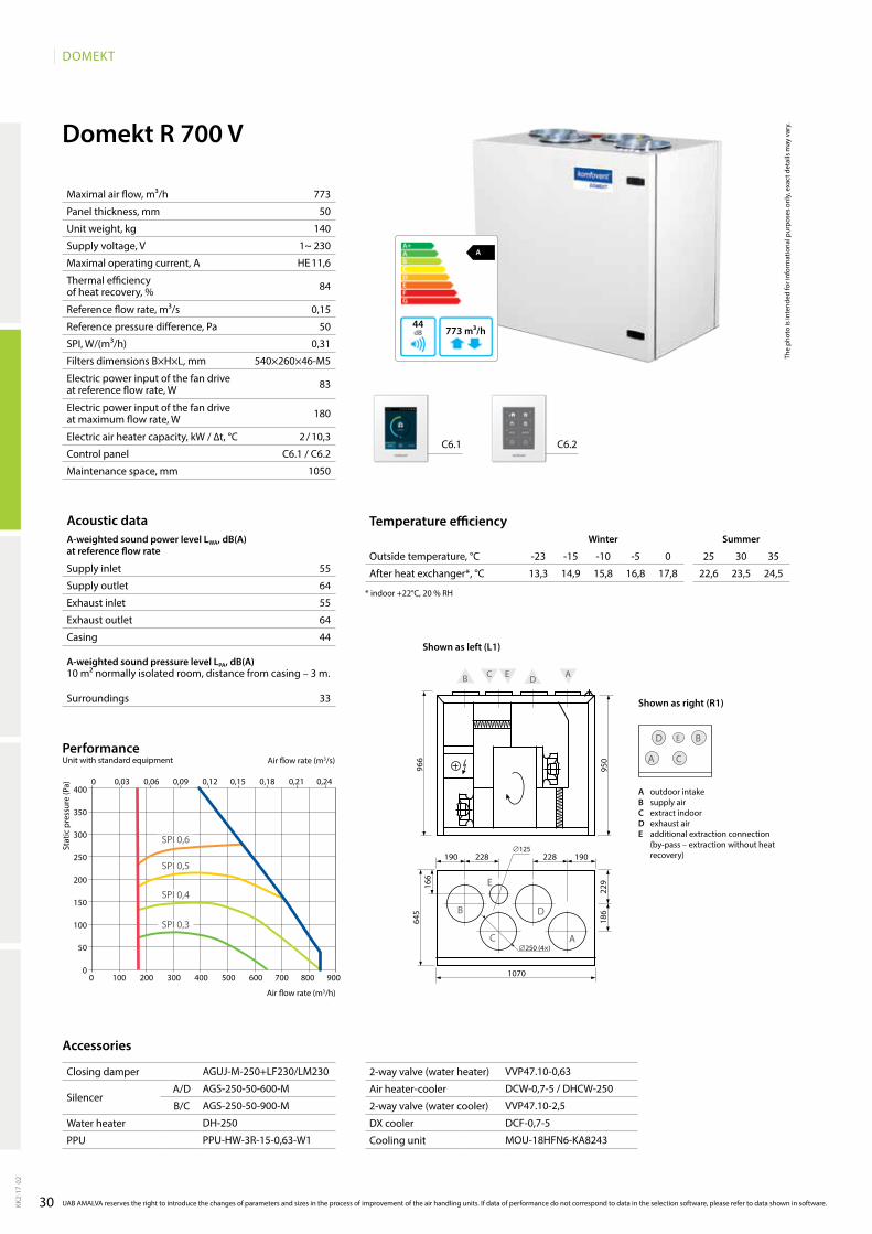
Domekt R 700 V
A
773 m³/h44
773
50
140
1~ 230
HE 11,6
84
0,15
50
0,31
540×260×46-M5
83
180
2 / 10,3
C6.1 / C6.2
1050
55
64
55
64
44
33
400
350
300
250
200
150
100
50
00 100 200 300 400 500 600 700 800 900
0 0,03 0,06 0,09 0,12 0,15 0,18 0,21 0,24
SPI 0,3
SPI 0,4
SPI 0,5
SPI 0,6
966
950
186
22916
664
5
∅250 (4×)
∅125228
1070
190 190228
D
AС
B
E
D AC EB
C6.1 C6.2
13,3 14,9 15,8 16,8 17,8 22,6 23,5 24,5
AgUJ-M-250+lF230/lM230
AgS-250-50-600-M
AgS-250-50-900-M
DH-250
PPU-HW-3R-15-0,63-W1
VVP47.10-0,63
DCW-0,7-5 / DHCW-250
VVP47.10-2,5
DCF-0,7-5
MOU-18HFN6-KA8243
D
A
B
C
E
KK2-
17-0
2
The
phot
o is
inte
nded
for i
nfor
mat
iona
l pur
pose
s on
ly, e
xact
det
ails
may
var
y.
Acoustic dataA-weighted sound power level LwA, dB(A)at reference flow rate
Supply inlet
Supply outlet
Exhaust inlet
Exhaust outlet
Casing
A-weighted sound pressure level LPA, dB(A) 10 m² normally isolated room, distance from casing – 3 m.
Surroundings
Maximal air flow, m³/h
Panel thickness, mm
Unit weight, kg
Supply voltage, V
Maximal operating current, A
Thermal efficiency of heat recovery, %
Reference flow rate, m³/s
Reference pressure difference, Pa
SPI, W/(m³/h)
Filters dimensions B×H×L, mm
Electric power input of the fan drive at reference flow rate, W
Electric power input of the fan drive at maximum flow rate, W
Electric air heater capacity, kW / ∆t, °C
Control panel
Maintenance space, mm
Stat
ic p
ress
ure
(Pa)
Air flow rate (m3/s)
Air flow rate (m3/h)
PerformanceUnit with standard equipment
UAB AMALVA reserves the right to introduce the changes of parameters and sizes in the process of improvement of the air handling units. If data of performance do not correspond to data in the selection software, please refer to data shown in software.
Temperature efficiencywinter Summer
Outside temperature, °C -23 -15 -10 -5 0 25 30 35
After heat exchanger*, °C
* indoor +22°C, 20 % RH
Accessories
Closing damper
SilencerA/D
B/C
Water heater
PPU
2-way valve (water heater)
Air heater-cooler
2-way valve (water cooler)
DX cooler
Cooling unit
Shown as left (L1)
Shown as right (R1)
A outdoor intakeB supply airC extract indoorD exhaust airE additional extraction connection
(by-pass – extraction without heat recovery)
31
DOMEKT
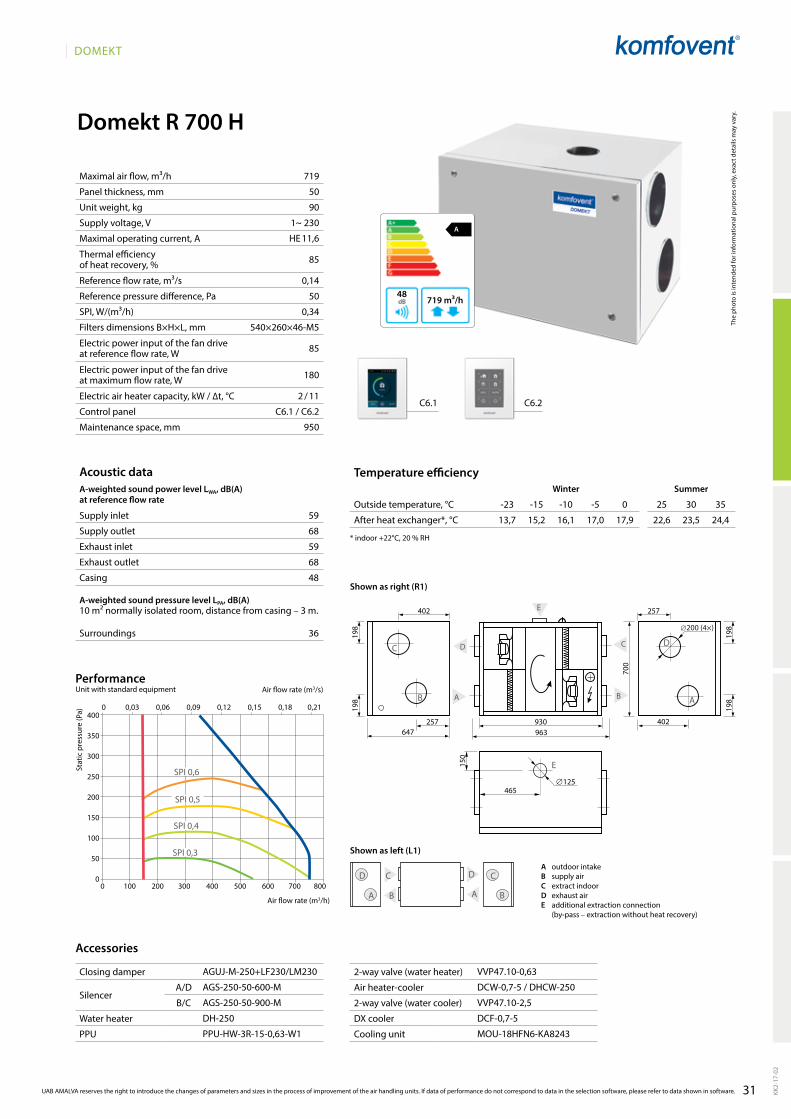
Domekt R 700 H
A
719 m³/h48
59
68
59
68
48
36
719
50
90
1~ 230
HE 11,6
85
0,14
50
0,34
540×260×46-M5
85
180
2 / 11
C6.1 / C6.2
950
0 100 200 300 400 500 600 700 800
400
350
300
250
200
150
100
50
0
0 0,03 0,06 0,09 0,12 0,15 0,18 0,21
SPI 0,3
SPI 0,4
SPI 0,5
SPI 0,6
D C
A B
257 930963
402
402 257
647
198
198
198
198
700
D
A
С
B
∅200 (4×)
465
150
∅125
E
D
A
C
B
DC
AB
E
C6.1 C6.2
13,7 15,2 16,1 17,0 17,9 22,6 23,5 24,4
AgUJ-M-250+lF230/lM230
AgS-250-50-600-M
AgS-250-50-900-M
DH-250
PPU-HW-3R-15-0,63-W1
VVP47.10-0,63
DCW-0,7-5 / DHCW-250
VVP47.10-2,5
DCF-0,7-5
MOU-18HFN6-KA8243
KK2-
17-0
2
UAB AMALVA reserves the right to introduce the changes of parameters and sizes in the process of improvement of the air handling units. If data of performance do not correspond to data in the selection software, please refer to data shown in software.
The
phot
o is
inte
nded
for i
nfor
mat
iona
l pur
pose
s on
ly, e
xact
det
ails
may
var
y.
Acoustic dataA-weighted sound power level LwA, dB(A)at reference flow rate
Supply inlet
Supply outlet
Exhaust inlet
Exhaust outlet
Casing
A-weighted sound pressure level LPA, dB(A) 10 m² normally isolated room, distance from casing – 3 m.
Surroundings
Maximal air flow, m³/h
Panel thickness, mm
Unit weight, kg
Supply voltage, V
Maximal operating current, A
Thermal efficiency of heat recovery, %
Reference flow rate, m³/s
Reference pressure difference, Pa
SPI, W/(m³/h)
Filters dimensions B×H×L, mm
Electric power input of the fan drive at reference flow rate, W
Electric power input of the fan drive at maximum flow rate, W
Electric air heater capacity, kW / ∆t, °C
Control panel
Maintenance space, mm
Stat
ic p
ress
ure
(Pa)
Air flow rate (m3/s)
Air flow rate (m3/h)
PerformanceUnit with standard equipment
Temperature efficiencyWinter Summer
Outside temperature, °C -23 -15 -10 -5 0 25 30 35
After heat exchanger*, °C
* indoor +22°C, 20 % RH
Accessories
Closing damper
SilencerA/D
B/C
Water heater
PPU
2-way valve (water heater)
Air heater-cooler
2-way valve (water cooler)
DX cooler
Cooling unit
A outdoor intakeB supply airC extract indoorD exhaust airE additional extraction connection
(by-pass – extraction without heat recovery)
Shown as right (R1)
Shown as left (L1)
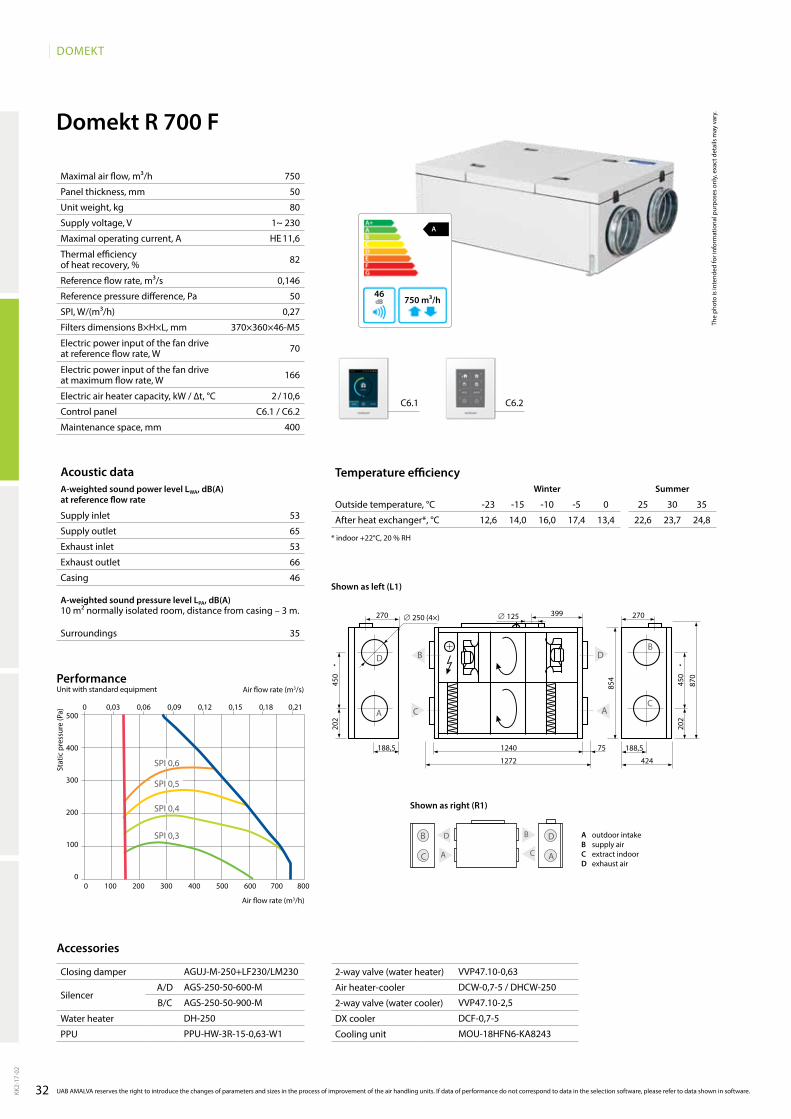
32
DOMEKT
Domekt R 700 F
A
750 m³/h46
750
50
80
1~ 230
HE 11,6
82
0,146
50
0,27
370×360×46-M5
70
166
2 / 10,6
C6.1 / C6.2
400
53
65
53
66
46
35
D
A C
B D
C A
B
0 100 200 300 400 500 600 700 800
500
400
300
200
100
0
0 0,03 0,06 0,09 0,12 0,15 0,18 0,21
SPI 0,3
SPI 0,6
SPI 0,5
SPI 0,4
188,5
270
188,51240 75
1272
450
450
870
854
202
202
∅ 250 (4×) ∅ 125
A
DB
C
424
D
C A
B
270399
C6.1 C6.2
12,6 14,0 16,0 17,4 13,4 22,6 23,7 24,8
AgUJ-M-250+lF230/lM230
AgS-250-50-600-M
AgS-250-50-900-M
DH-250
PPU-HW-3R-15-0,63-W1
VVP47.10-0,63
DCW-0,7-5 / DHCW-250
VVP47.10-2,5
DCF-0,7-5
MOU-18HFN6-KA8243
KK2-
17-0
2
The
phot
o is
inte
nded
for i
nfor
mat
iona
l pur
pose
s on
ly, e
xact
det
ails
may
var
y.
Acoustic dataA-weighted sound power level LwA, dB(A)at reference flow rate
Supply inlet
Supply outlet
Exhaust inlet
Exhaust outlet
Casing
A-weighted sound pressure level LPA, dB(A) 10 m² normally isolated room, distance from casing – 3 m.
Surroundings
Maximal air flow, m³/h
Panel thickness, mm
Unit weight, kg
Supply voltage, V
Maximal operating current, A
Thermal efficiency of heat recovery, %
Reference flow rate, m³/s
Reference pressure difference, Pa
SPI, W/(m³/h)
Filters dimensions B×H×L, mm
Electric power input of the fan drive at reference flow rate, W
Electric power input of the fan drive at maximum flow rate, W
Electric air heater capacity, kW / ∆t, °C
Control panel
Maintenance space, mm
Stat
ic p
ress
ure
(Pa)
Air flow rate (m3/s)
Air flow rate (m3/h)
PerformanceUnit with standard equipment
UAB AMALVA reserves the right to introduce the changes of parameters and sizes in the process of improvement of the air handling units. If data of performance do not correspond to data in the selection software, please refer to data shown in software.
Temperature efficiencywinter Summer
Outside temperature, °C -23 -15 -10 -5 0 25 30 35
After heat exchanger*, °C
* indoor +22°C, 20 % RH
Accessories
Closing damper
SilencerA/D
B/C
Water heater
PPU
2-way valve (water heater)
Air heater-cooler
2-way valve (water cooler)
DX cooler
Cooling unit
A outdoor intakeB supply airC extract indoorD exhaust air
Shown as right (R1)
Shown as left (L1)
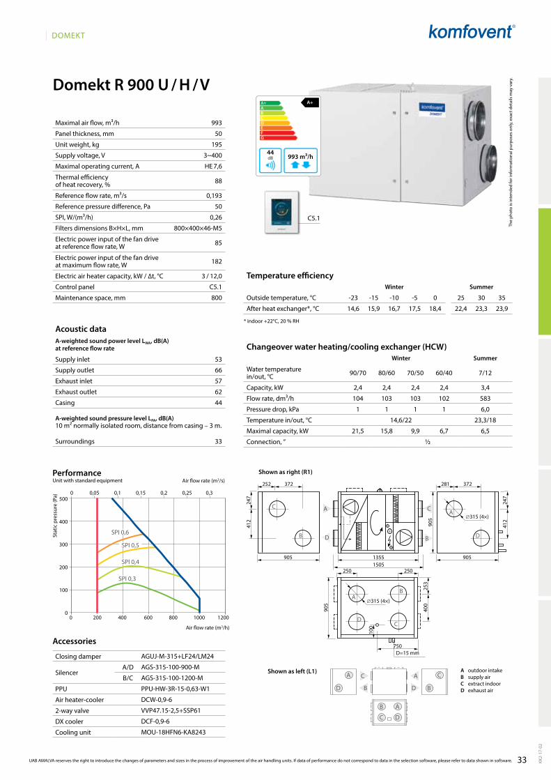
33
DOMEKT
53
66
57
62
44
33
Domekt R 900 U / H / V
2,4 2,4 2,4 2,4 3,4
104 103 103 102 583
1 1 1 1 6,0
14,6/22 23,3/18
21,5 15,8 9,9 6,7 6,5
½
281252 372372
905905 13551505
905
905
247
247
412
412
С
B D
A
∅315 (4×)
∅315 (4×)
750
250
100
253
400
C
B
D
A
D=15 mm
A
BD
C
250
C
DB
A C
C
A
A
B
B
D
D
C5.1
A+
993 m³/h44
14,6 15,9 16,7 17,5 18,4 22,4 23,3 23,9
AgUJ-M-315+lF24/lM24
AgS-315-100-900-M
AgS-315-100-1200-M
PPU-HW-3R-15-0,63-W1
DCW-0,9-6
VVP47.15-2,5+SSP61
DCF-0,9-6
MOU-18HFN6-KA8243
993
50
195
3~400
HE 7,6
88
0,193
50
0,26
800×400×46-M5
85
182
3 / 12,0
C5.1
800
500
400
300
200
100
00 200 400 600 800 1000 1200
0 0,05 0,1 0,15 0,2 0,25 0,3
SPI 0,3
SPI 0,6
SPI 0,5
SPI 0,4
KK2-
17-0
2
UAB AMALVA reserves the right to introduce the changes of parameters and sizes in the process of improvement of the air handling units. If data of performance do not correspond to data in the selection software, please refer to data shown in software.
Closing damper
SilencerA/D
B/C
PPU
Air heater-cooler
2-way valve
DX cooler
Cooling unit
The
phot
o is
inte
nded
for i
nfor
mat
iona
l pur
pose
s on
ly, e
xact
det
ails
may
var
y.
Acoustic dataA-weighted sound power level LwA, dB(A)at reference flow rate
Supply inlet
Supply outlet
Exhaust inlet
Exhaust outlet
Casing
A-weighted sound pressure level LPA, dB(A) 10 m² normally isolated room, distance from casing – 3 m.
Surroundings
Maximal air flow, m³/h
Panel thickness, mm
Unit weight, kg
Supply voltage, V
Maximal operating current, A
Thermal efficiency of heat recovery, %
Reference flow rate, m³/s
Reference pressure difference, Pa
SPI, W/(m³/h)
Filters dimensions B×H×L, mm
Electric power input of the fan drive at reference flow rate, W
Electric power input of the fan drive at maximum flow rate, W
Electric air heater capacity, kW / ∆t, °C
Control panel
Maintenance space, mm
Stat
ic p
ress
ure
(Pa)
Air flow rate (m3/s)
Air flow rate (m3/h)
PerformanceUnit with standard equipment
Temperature efficiencyWinter Summer
Outside temperature, °C -23 -15 -10 -5 0 25 30 35
After heat exchanger*, °C
* indoor +22°C, 20 % RH
Accessories
Changeover water heating/cooling exchanger (HCW)Winter Summer
Water temperature in/out, °C 90/70 80/60 70/50 60/40 7/12
Capacity, kW
Flow rate, dm³/h
Pressure drop, kPa
Temperature in/out, °C
Maximal capacity, kW
Connection, ”
Shown as right (R1)
Shown as left (L1) A outdoor intakeB supply airC extract indoorD exhaust air
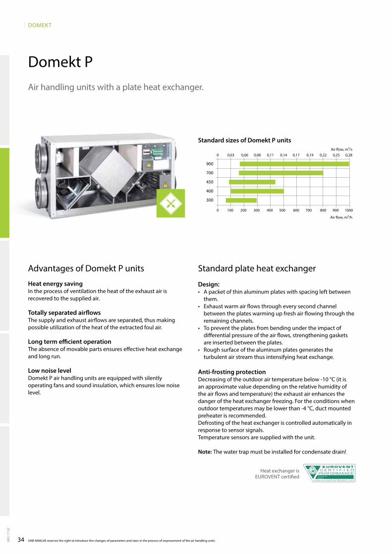
34
DOMEKT
Domekt P
0 100 200 300 400 500 600 700 800 900 1000
0 0,03 0,06 0,08 0,11 0,14 0,17 0,19 0,22 0,25 0,28
900
700
450
400
300
UAB AMALVA reserves the right to introduce the changes of parameters and sizes in the process of improvement of the air handling units.KK2-
17-0
2
Advantages of Domekt P units
Heat energy savingIn the process of ventilation the heat of the exhaust air is recovered to the supplied air.
Totally separated airflowsThe supply and exhaust airflows are separated, thus making possible utilization of the heat of the extracted foul air.
Long term efficient operationThe absence of movable parts ensures effective heat exchange and long run.
Low noise levelDomekt P air handling units are equipped with silently operating fans and sound insulation, which ensures low noise level.
Standard plate heat exchanger
Design:• A packet of thin aluminum plates with spacing left bet ween
them.• Exhaust warm air flows through every second channel
between the plates warming up fresh air flowing through the remaining channels.
• To prevent the plates from bending under the impact of differential pressure of the air flows, strengthening gaskets are inserted between the plates.
• Rough surface of the aluminum plates generates the turbulent air stream thus intensifying heat exchange.
Anti-frosting protectionDecreasing of the outdoor air temperature below -10 °C (it is an approximate value depending on the relative humidity of the air flows and temperature) the exhaust air enhances the danger of the heat exchanger freezing. For the conditions when outdoor temperatures may be lower than -4 °C, duct mounted preheater is recommended.Defrosting of the heat exchanger is controlled automa tically in response to sensor signals. Temperature sensors are supplied with the unit.
Note: The water trap must be installed for condensate drain!
Standard sizes of Domekt P units
Air flow, m³/h
Air flow, m³/s
Air handling units with a plate heat exchanger.
Heat exchanger is EUROVENT certified No: 03.01.241
Range: H
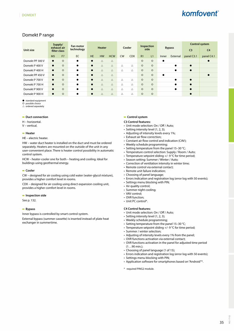
35
DOMEKT
KK2-
17-0
2
Domekt P range
Duct connection
H – horizontal.V – vertical.
Heater
HE – electric heater.
HW – water duct heater is installed on the duct and must be ordered separately. Heaters are mounted on the outside of the unit in any user-convenient place. There is heater control possibility in automatic control system.
HCW – heater-cooler one for both – heating and cooling. Ideal for buildings using geothermal energy.
Cooler
CW – designed for air cooling using cold water (water-glycol mixture), provides a higher comfort level in rooms.
CDX – designed for air cooling using direct expansion cooling unit, provides a higher comfort level in rooms.
Inspection side
See p. 132.
Bypass
Inner bypass is controlled by smart control system.
External bypass (summer cassette) is inserted instead of plate heat exchanger in summertime.
Control system
C3 Control features:• Unitmodeselection:On/Off/Auto;• Settingintensitylevel(1,2,3);• Adjustingofintensitylevelsevery1%;• Exhaustairflowcorrection;• Constantairflowcontrolandindication(CAV);• Weeklyscheduleprogramming;• Settingtemperaturefromthepanel15–30°C;• Temperaturecontrolselection:Supply/Room/Auto;• Temperaturesetpointsliding+/-9°Cfortimeperiod;• Seasonsetting:Summer/Winter/Auto;• Correctionofventilationintensityinwintertime;• Remotecontrolviaexternalcontact;• Remoteunitfailureindication;• Choosingofpanellanguage;• Errorsindicationandregistrationlog(errorlogwith50events);• SettingsmenublockingwithPIN;• Airqualitycontrol;• Summernightcooling;• VAVcontrol;• OVRfunction;• UnitPCcontrol*.
C4 Control features:• Unitmodeselection:On/Off/Auto;• Settingintensitylevel(1,2,3);• Weeklyscheduleprogramming;• Settingtemperaturefromthepanel15–30°C;• Temperaturesetpointsliding+/-9°Cfortimeperiod;• Summer/winterselection;• Adjustingofintensitylevelsevery1%fromthepanel;• OVRfunctionsactivationviaexternalcontact;• OVRfunctionsactivationinthepanelforadjustedtimeperiod
(1…90 min.);• Choosingofpanellanguage(1of15);• Errorsindicationandregistrationlog(errorlogwith50events);• SettingsmenublockingwithPIN;• Applicationsoftwareforsmartphonesbasedon“Android”*.
* required PINg2 module.
� standard equipment� possible choice ordered separately
Unit size
Supply/exhaust air filter class
Fan motor technology Heater Cooler Inspection
side BypassControl system
C3 C4
M5 F7 EC HE HW HCW CW CDX R1 l1 Inner External panel C3.1 panel C4.1
Domekt PP 300 V � � � � � � � �
Domekt P 400 V � � � � � � � �
Domekt P 400 H � � � � � � � �
Domekt PP 450 V � � � � � � � �
Domekt P 700 V � � � � � � � �
Domekt P 700 H � � � � � � � �
Domekt P 900 V � � � � � � � �
Domekt P 900 H � � � � � � �
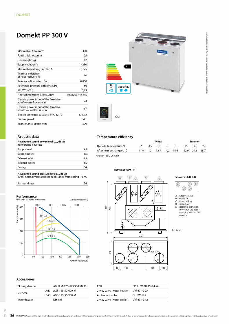
36
DOMEKT
A
300 m³/h34
300
25
42
1~230
HE 5,5
76
0,058
50
0,23
300×200×46-M5
23
67
1 / 13,2
C4.1
300
Domekt PP 300 V
45
65
45
65
34
24
A E D C B
A E B
D C
70072
7
740
340
85 180 185 110
D
AE
C
B
D=15 mm
11,9 12 12,7 14,2 15,6 22,9 24,3 25,7
C4.1
AgUJ-M-125+lF230/lM230
AgS-125-50-600-M
AgS-125-50-900-M
DH-125
PPU-HW-3R-15-0,4-W1
VVP47.10-0,4
DHCW-125
VVP47.10-1,6
0 0,02 0,04 0,06 0,08
0 50 100 150 200 250 300 350
400
300
200
100
0
SPI 0,6
SPI 0,4
SPI 0,3
SPI 0,5
KK2-
17-0
2
The
phot
o is
inte
nded
for i
nfor
mat
iona
l pur
pose
s on
ly, e
xact
det
ails
may
var
y.
Acoustic dataA-weighted sound power level LwA, dB(A)at reference flow rate
Supply inlet
Supply outlet
Exhaust inlet
Exhaust outlet
Casing
A-weighted sound pressure level LPA, dB(A) 10 m² normally isolated room, distance from casing – 3 m.
Surroundings
Maximal air flow, m³/h
Panel thickness, mm
Unit weight, kg
Supply voltage, V
Maximal operating current, A
Thermal efficiency of heat recovery, %
Reference flow rate, m³/s
Reference pressure difference, Pa
SPI, W/(m³/h)
Filters dimensions B×H×L, mm
Electric power input of the fan drive at reference flow rate, W
Electric power input of the fan drive at maximum flow rate, W
Electric air heater capacity, kW / ∆t, °C
Control panel
Maintenance space, mm
Stat
ic p
ress
ure
(Pa)
Air flow rate (m3/s)
Air flow rate (m3/h)
PerformanceUnit with standard equipment
UAB AMALVA reserves the right to introduce the changes of parameters and sizes in the process of improvement of the air handling units. If data of performance do not correspond to data in the selection software, please refer to data shown in software.
Temperature efficiencywinter Summer
Outside temperature, °C -23 -15 -10 -5 0 25 30 35
After heat exchanger*, °C
* indoor +22°C, 20 % RH
Accessories
Closing damper
SilencerA/D
B/C
Water heater
PPU
2-way valve (water heater)
Air heater-cooler
2-way valve (water cooler)
A outdoor intakeB supply airC extract indoorD exhaust airE additional extraction
connection (by-pass – extraction without heat recovery)
Shown as right (R1)
Shown as left (L1)
125 (5×)

37
DOMEKT
Domekt P 400 V
B
480 m³/h43
900
780
920
390
145 145
150
90
200 200
D
AС
B
160 (4×)
D A C
B
480
45
62
1~230
HE 10,8
56
0,093
50
0,21
300×195×46-M5
33
93
2 / 16,5
C3.1
900
50
63
50
64
43
34
A DCB
D=15 mm
2,4 5,4 7,5 9,7 12 23,4 25,6 27,9
C3.1
AgUJ-M-160+lF230/lM230
AgS-160-50-600-M
AgS-160-50-900-M
DH-160
PPU-HW-3R-15-0,4-W1
VVP47.10-0,4
DCW-0,4-3 / DHCW-160
VVP47.10-1,6
DCF-0,4-3
0 0,02 0,04 0,06 0,08 0,10 0,12 0,14 0,16
0 100 200 300 400 500
500
400
300
200
100
0
SPI 0,6
SPI 0,5
SPI 0,4
SPI 0,3
KK2-
17-0
2
UAB AMALVA reserves the right to introduce the changes of parameters and sizes in the process of improvement of the air handling units. If data of performance do not correspond to data in the selection software, please refer to data shown in software.
The
phot
o is
inte
nded
for i
nfor
mat
iona
l pur
pose
s on
ly, e
xact
det
ails
may
var
y.
Acoustic dataA-weighted sound power level LwA, dB(A)at reference flow rate
Supply inlet
Supply outlet
Exhaust inlet
Exhaust outlet
Casing
A-weighted sound pressure level LPA, dB(A) 10 m² normally isolated room, distance from casing – 3 m.
Surroundings
Maximal air flow, m³/h
Panel thickness, mm
Unit weight, kg
Supply voltage, V
Maximal operating current, A
Thermal efficiency of heat recovery, %
Reference flow rate, m³/s
Reference pressure difference, Pa
SPI, W/(m³/h)
Filters dimensions B×H×L, mm
Electric power input of the fan drive at reference flow rate, W
Electric power input of the fan drive at maximum flow rate, W
Electric air heater capacity, kW / ∆t, °C
Control panel
Maintenance space, mm
Stat
ic p
ress
ure
(Pa)
Air flow rate (m3/s)
Air flow rate (m3/h)
PerformanceUnit with standard equipment
Temperature efficiencyWinter Summer
Outside temperature, °C -23 -15 -10 -5 0 25 30 35
After heat exchanger*, °C
* indoor +22°C, 20 % RH
Accessories
Closing damper
SilencerA/D
B/C
Water heater
PPU
2-way valve (water heater)
Air heater-cooler
2-way valve (water cooler)
DX cooler
Cooling unit
A outdoor intakeB supply airC extract indoorD exhaust air
Shown as right (R1)
Shown as left (L1)

38
DOMEKT
Domekt P 400 H
B
480 m³/h42
480
45
55
1~230
HE 10,8
56
0,093
50
0,21
300×195×46-M5
33
93
2 / 16,5
C3.1
1000
50
61
50
61
42
32
B
A C
D
1000 195
200 (4x)
600
145
145
3901150
C
D D
AA
B
D=15 mm
2,4 5,4 7,5 9,7 12 23,4 25,6 27,9
C3.1
AgUJ-M-200+lF230/lM230
AgS-200-50-600-M
AgS-200-50-900-M
DH-200
PPU-HW-3R-15-0,4-W1
VVP47.10-0,4
DCW-0,4-3 / DHCW-200
VVP47.10-1,6
DCF-0,4-3
0 0,02 0,04 0,06 0,08 0,10 0,12
0 100 200 300 400 500
500
400
300
200
100
0
SPI 0,6
SPI 0,4
SPI 0,3
SPI 0,5
KK2-
17-0
2
The
phot
o is
inte
nded
for i
nfor
mat
iona
l pur
pose
s on
ly, e
xact
det
ails
may
var
y.
Acoustic dataA-weighted sound power level LwA, dB(A)at reference flow rate
Supply inlet
Supply outlet
Exhaust inlet
Exhaust outlet
Casing
A-weighted sound pressure level LPA, dB(A) 10 m² normally isolated room, distance from casing – 3 m.
Surroundings
Maximal air flow, m³/h
Panel thickness, mm
Unit weight, kg
Supply voltage, V
Maximal operating current, A
Thermal efficiency of heat recovery, %
Reference flow rate, m³/s
Reference pressure difference, Pa
SPI, W/(m³/h)
Filters dimensions B×H×L, mm
Electric power input of the fan drive at reference flow rate, W
Electric power input of the fan drive at maximum flow rate, W
Electric air heater capacity, kW / ∆t, °C
Control panel
Maintenance space, mm
Stat
ic p
ress
ure
(Pa)
Air flow rate (m3/s)
Air flow rate (m3/h)
PerformanceUnit with standard equipment
UAB AMALVA reserves the right to introduce the changes of parameters and sizes in the process of improvement of the air handling units. If data of performance do not correspond to data in the selection software, please refer to data shown in software.
Temperature efficiencywinter Summer
Outside temperature, °C -23 -15 -10 -5 0 25 30 35
After heat exchanger*, °C
* indoor +22°C, 20 % RH
Accessories
Closing damper
SilencerA/D
B/C
Water heater
PPU
2-way valve (water heater)
Air heater-cooler
2-way valve (water cooler)
DX cooler
Cooling unit
A outdoor intakeB supply airC extract indoorD exhaust air
Shown as right (R1)
Shown as left (L1)
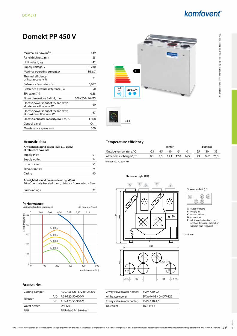
39
DOMEKT
449
25
42
1~ 230
HE 6,7
71
0,087
50
0,38
300×200×46-M5
60
167
1 / 8,8
C4.1
300
B
449 m³/h40
51
74
51
74
40
29
Domekt PP 450 V
A E D C B
A E B
D C
70072
7
740
340
85 180 185 110
D
AE
C
B
125 (5×)
D=15 mm
C4.1
8,1 9,5 11,1 12,8 14,5 23 24,7 26,3
AgUJ-M-125+lF230/lM230
AgS-125-50-600-M
AgS-125-50-900-M
DH-125
PPU-HW-3R-15-0,4-W1
VVP47.10-0,4
DCW-0,4-3 / DHCW-125
VVP47.10-1,6
DCF-0,4-3
SPI 0,6
SPI 0,4
SPI 0,3
SPI 0,5
0 100 200 300 400 500
500
400
300
200
100
0
0 0,02 0,04 0,06 0,08 0,10 0,12
KK2-
17-0
2
UAB AMALVA reserves the right to introduce the changes of parameters and sizes in the process of improvement of the air handling units. If data of performance do not correspond to data in the selection software, please refer to data shown in software.
The
phot
o is
inte
nded
for i
nfor
mat
iona
l pur
pose
s on
ly, e
xact
det
ails
may
var
y.
Acoustic dataA-weighted sound power level LwA, dB(A)at reference flow rate
Supply inlet
Supply outlet
Exhaust inlet
Exhaust outlet
Casing
A-weighted sound pressure level LPA, dB(A) 10 m² normally isolated room, distance from casing – 3 m.
Surroundings
Maximal air flow, m³/h
Panel thickness, mm
Unit weight, kg
Supply voltage, V
Maximal operating current, A
Thermal efficiency of heat recovery, %
Reference flow rate, m³/s
Reference pressure difference, Pa
SPI, W/(m³/h)
Filters dimensions B×H×L, mm
Electric power input of the fan drive at reference flow rate, W
Electric power input of the fan drive at maximum flow rate, W
Electric air heater capacity, kW / ∆t, °C
Control panel
Maintenance space, mm
Stat
ic p
ress
ure
(Pa)
Air flow rate (m3/s)
Air flow rate (m3/h)
PerformanceUnit with standard equipment
Temperature efficiencyWinter Summer
Outside temperature, °C -23 -15 -10 -5 0 25 30 35
After heat exchanger*, °C
* indoor +22°C, 20 % RH
Accessories
Closing damper
SilencerA/D
B/C
Water heater
PPU
2-way valve (water heater)
Air heater-cooler
2-way valve (water cooler)
DX cooler
Cooling unit
A outdoor intakeB supply airC extract indoorD exhaust airE additional extraction con-
nection (by-pass – extraction without heat recovery)
Shown as right (R1)
Shown as left (L1)

40
DOMEKT
Domekt P 700 V
B
797 m³/h46
797
45
85
1~230
HE 14,1
55
0,155
50
0,25
400×235×46-M5
69
181
2,5 / 12,5
C3.1
400
52
65
52
65
46
35
1000
950
1090
490
150 170
156
156
220 210
D
AС
B
200 (4×)
D A C
B
A DCB
D=15 mm
C3.1
1,9 5,1 7,2 9,5 11,8 23,4 25,7 28
AgUJ-M-200+lF230/lM230
AgS-200-50-600-M
AgS-200-50-900-M
DH-200
PPU-HW-3R-15-0,4-W1
VVP47.10-0,4
DCW-0,7-5 / DHCW-200
VVP47.10-2,5
DCF-0,7-5
MOU-18HFN6-KA8243
0 100 200 300 400 500 600 700 800 900
0 0,03 0,06 0,09 0,12 0,15 0,18 0,21 0,24600
500
400
300
200
100
0
SPI 0,6
SPI 0,4
SPI 0,3
SPI 0,5
KK2-
17-0
2
The
phot
o is
inte
nded
for i
nfor
mat
iona
l pur
pose
s on
ly, e
xact
det
ails
may
var
y.
Acoustic dataA-weighted sound power level LwA, dB(A)at reference flow rate
Supply inlet
Supply outlet
Exhaust inlet
Exhaust outlet
Casing
A-weighted sound pressure level LPA, dB(A) 10 m² normally isolated room, distance from casing – 3 m.
Surroundings
Maximal air flow, m³/h
Panel thickness, mm
Unit weight, kg
Supply voltage, V
Maximal operating current, A
Thermal efficiency of heat recovery, %
Reference flow rate, m³/s
Reference pressure difference, Pa
SPI, W/(m³/h)
Filters dimensions B×H×L, mm
Electric power input of the fan drive at reference flow rate, W
Electric power input of the fan drive at maximum flow rate, W
Electric air heater capacity, kW / ∆t, °C
Control panel
Maintenance space, mm
Stat
ic p
ress
ure
(Pa)
Air flow rate (m3/s)
Air flow rate (m3/h)
PerformanceUnit with standard equipment
UAB AMALVA reserves the right to introduce the changes of parameters and sizes in the process of improvement of the air handling units. If data of performance do not correspond to data in the selection software, please refer to data shown in software.
Temperature efficiencywinter Summer
Outside temperature, °C -23 -15 -10 -5 0 25 30 35
After heat exchanger*, °C
* indoor +22°C, 20 % RH
Accessories
Closing damper
SilencerA/D
B/C
Water heater
PPU
2-way valve (water heater)
Air heater-cooler
2-way valve (water cooler)
DX cooler
Cooling unit
A outdoor intakeB supply airC extract indoorD exhaust air
Shown as right (R1)
Shown as left (L1)

41
DOMEKT
Domekt P 700 H
B
816 m³/h46
816
45
75
1~230
HE 14,1
55
0,159
50
0,26
400×235×46-M5
75
181
2,5 / 12,2
C3.1
400
52
66
52
66
46
35
1170 245
250 (4×)
600
145
160
4951325
C
DD
A A
B
B
A C
D
C3.1
1,9 5,0 7,1 9,4 11,8 23,4 25,7 28
AgUJ-M-250+lF230/lM230
AgS-250-50-600-M
AgS-250-50-900-M
DH-250
PPU-HW-3R-15-0,63-W1
VVP47.10-0,63
DCW-0,7-5 / DHCW-250
VVP47.10-2,5
DCF-0,7-5
MOU-18HFN6-KA8243
0 100 200 300 400 500 600 700 800 900
600
500
400
300
200
100
0
0 0,05 0,1 0,15 0,2 0,25
SPI 0,6
SPI 0,4
SPI 0,3
SPI 0,5
KK2-
17-0
2
UAB AMALVA reserves the right to introduce the changes of parameters and sizes in the process of improvement of the air handling units. If data of performance do not correspond to data in the selection software, please refer to data shown in software.
The
phot
o is
inte
nded
for i
nfor
mat
iona
l pur
pose
s on
ly, e
xact
det
ails
may
var
y.
Acoustic dataA-weighted sound power level LwA, dB(A)at reference flow rate
Supply inlet
Supply outlet
Exhaust inlet
Exhaust outlet
Casing
A-weighted sound pressure level LPA, dB(A) 10 m² normally isolated room, distance from casing – 3 m.
Surroundings
Maximal air flow, m³/h
Panel thickness, mm
Unit weight, kg
Supply voltage, V
Maximal operating current, A
Thermal efficiency of heat recovery, %
Reference flow rate, m³/s
Reference pressure difference, Pa
SPI, W/(m³/h)
Filters dimensions B×H×L, mm
Electric power input of the fan drive at reference flow rate, W
Electric power input of the fan drive at maximum flow rate, W
Electric air heater capacity, kW / ∆t, °C
Control panel
Maintenance space, mm
Stat
ic p
ress
ure
(Pa)
Air flow rate (m3/s)
Air flow rate (m3/h)
PerformanceUnit with standard equipment
Temperature efficiencyWinter Summer
Outside temperature, °C -23 -15 -10 -5 0 25 30 35
After heat exchanger*, °C
* indoor +22°C, 20 % RH
Accessories
Closing damper
SilencerA/D
B/C
Water heater
PPU
2-way valve (water heater)
Air heater-cooler
2-way valve (water cooler)
DX cooler
Cooling unit
A outdoor intakeB supply airC extract indoorD exhaust air
Shown as right (R1)
Shown as left (L1)
D=15 mm
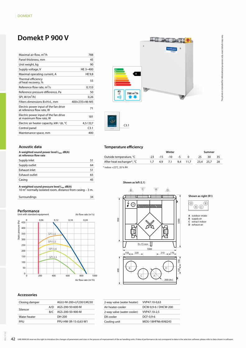
42
DOMEKT
B
788 m³/h45
788
45
90
HE 3~400
HE 9,8
55
0,153
50
0,26
400×235×46-M5
71
181
4,5 / 22,7
C3.1
400
51
64
51
65
45
34
Domekt P 900 V
1000
950
1090
490
150 170
156
156
220 210
D
AС
B
200 (4×)
D A C
B
A DCB
D=15 mm
1,7 4,9 7,1 9,4 11,7 23,4 25,7 28
C3.1
AgUJ-M-200+lF230/lM230
AgS-200-50-600-M
AgS-200-50-900-M
DH-200
PPU-HW-3R-15-0,63-W1
VVP47.10-0,63
DCW-0,9-6 / DHCW-200
VVP47.10-2,5
DCF-0,9-6
MOU-18HFN6-KA8243
0 200 400 600 800 1000
0 0,06 0,12 0,18 0,24450
400
350
300
250
200
150
100
50
0
SPI 0,6
SPI 0,4
SPI 0,3
SPI 0,5
KK2-
17-0
2
The
phot
o is
inte
nded
for i
nfor
mat
iona
l pur
pose
s on
ly, e
xact
det
ails
may
var
y.
Acoustic dataA-weighted sound power level LwA, dB(A)at reference flow rate
Supply inlet
Supply outlet
Exhaust inlet
Exhaust outlet
Casing
A-weighted sound pressure level LPA, dB(A) 10 m² normally isolated room, distance from casing – 3 m.
Surroundings
Maximal air flow, m³/h
Panel thickness, mm
Unit weight, kg
Supply voltage, V
Maximal operating current, A
Thermal efficiency of heat recovery, %
Reference flow rate, m³/s
Reference pressure difference, Pa
SPI, W/(m³/h)
Filters dimensions B×H×L, mm
Electric power input of the fan drive at reference flow rate, W
Electric power input of the fan drive at maximum flow rate, W
Electric air heater capacity, kW / ∆t, °C
Control panel
Maintenance space, mm
Stat
ic p
ress
ure
(Pa)
Air flow rate (m3/s)
Air flow rate (m3/h)
PerformanceUnit with standard equipment
UAB AMALVA reserves the right to introduce the changes of parameters and sizes in the process of improvement of the air handling units. If data of performance do not correspond to data in the selection software, please refer to data shown in software.
Temperature efficiencywinter Summer
Outside temperature, °C -23 -15 -10 -5 0 25 30 35
After heat exchanger*, °C
* indoor +22°C, 20 % RH
Accessories
Closing damper
SilencerA/D
B/C
Water heater
PPU
2-way valve (water heater)
Air heater-cooler
2-way valve (water cooler)
DX cooler
Cooling unit
A outdoor intakeB supply airC extract indoorD exhaust air
Shown as right (R1)
Shown as left (L1)
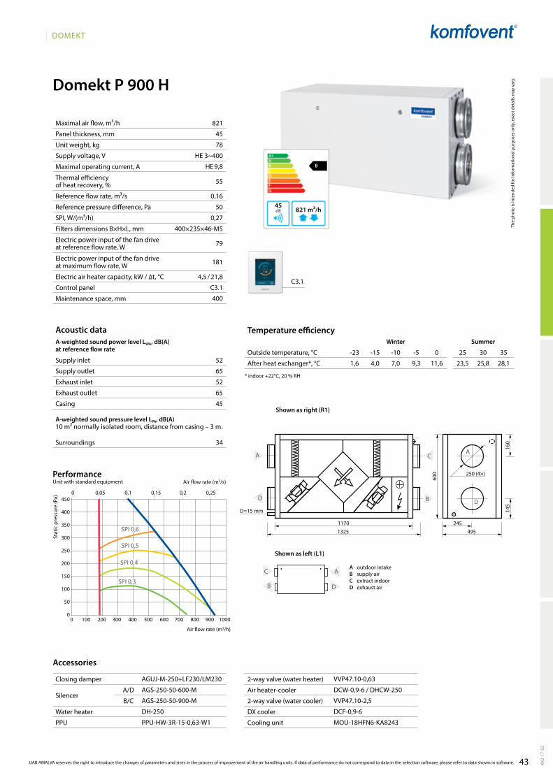
43
DOMEKT
B
821 m³/h45
821
45
78
HE 3~400
HE 9,8
55
0,16
50
0,27
400×235×46-M5
79
181
4,5 / 21,8
C3.1
400
52
65
52
65
45
34
Domekt P 900 H
1170 245
250 (4×)
600
145
160
4951325
C
D D
A A
B
B
A C
D
D=15 mm
C3.1
1,6 4,0 7,0 9,3 11,6 23,5 25,8 28,1
AgUJ-M-250+lF230/lM230
AgS-250-50-600-M
AgS-250-50-900-M
DH-250
PPU-HW-3R-15-0,63-W1
VVP47.10-0,63
DCW-0,9-6 / DHCW-250
VVP47.10-2,5
DCF-0,9-6
MOU-18HFN6-KA8243
0 100 200 300 400 500 600 700 800 900 1000
0 0,05 0,1 0,15 0,2 0,25450
400
350
300
250
200
150
100
50
0
SPI 0,6
SPI 0,4
SPI 0,3
SPI 0,5KK
2-17
-02
UAB AMALVA reserves the right to introduce the changes of parameters and sizes in the process of improvement of the air handling units. If data of performance do not correspond to data in the selection software, please refer to data shown in software.
The
phot
o is
inte
nded
for i
nfor
mat
iona
l pur
pose
s on
ly, e
xact
det
ails
may
var
y.
Acoustic dataA-weighted sound power level LwA, dB(A)at reference flow rate
Supply inlet
Supply outlet
Exhaust inlet
Exhaust outlet
Casing
A-weighted sound pressure level LPA, dB(A) 10 m² normally isolated room, distance from casing – 3 m.
Surroundings
Maximal air flow, m³/h
Panel thickness, mm
Unit weight, kg
Supply voltage, V
Maximal operating current, A
Thermal efficiency of heat recovery, %
Reference flow rate, m³/s
Reference pressure difference, Pa
SPI, W/(m³/h)
Filters dimensions B×H×L, mm
Electric power input of the fan drive at reference flow rate, W
Electric power input of the fan drive at maximum flow rate, W
Electric air heater capacity, kW / ∆t, °C
Control panel
Maintenance space, mm
Stat
ic p
ress
ure
(Pa)
Air flow rate (m3/s)
Air flow rate (m3/h)
PerformanceUnit with standard equipment
Temperature efficiencyWinter Summer
Outside temperature, °C -23 -15 -10 -5 0 25 30 35
After heat exchanger*, °C
* indoor +22°C, 20 % RH
Accessories
Closing damper
SilencerA/D
B/C
Water heater
PPU
2-way valve (water heater)
Air heater-cooler
2-way valve (water cooler)
DX cooler
Cooling unit
Shown as right (R1)
Shown as left (L1)
A outdoor intakeB supply airC extract indoorD exhaust air
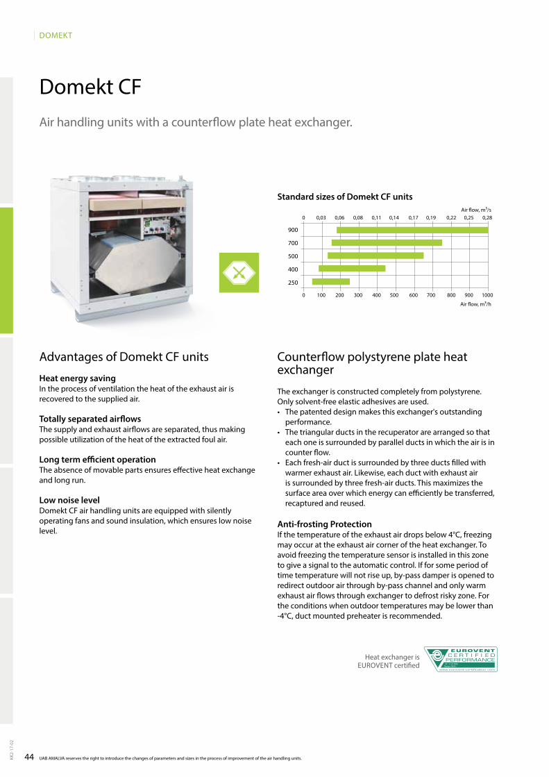
44
DOMEKT
Domekt CF
0 0,03 0,06 0,08 0,11 0,14 0,17 0,19 0,22 0,25 0,28
0 100 200 300 400 500 600 700 800 900 1000
900
700
500
400
250
UAB AMALVA reserves the right to introduce the changes of parameters and sizes in the process of improvement of the air handling units.KK2-
17-0
2
Advantages of Domekt CF units
Heat energy savingIn the process of ventilation the heat of the exhaust air is recovered to the supplied air.
Totally separated airflowsThe supply and exhaust airflows are separated, thus making possible utilization of the heat of the extracted foul air.
Long term efficient operationThe absence of movable parts ensures effective heat exchange and long run.
Low noise levelDomekt CF air handling units are equipped with silently operating fans and sound insulation, which ensures low noise level.
Air handling units with a counterflow plate heat exchanger.
Counterflow polystyrene plate heat exchanger
The exchanger is constructed completely from polystyrene. Only solvent-free elastic adhesives are used.• The patented design makes this exchanger's outstanding
performance.• The triangular ducts in the recuperator are arranged so that
each one is surrounded by parallel ducts in which the air is in counter flow.
• Each fresh-air duct is surrounded by three ducts filled with warmer exhaust air. likewise, each duct with exhaust air is surrounded by three fresh-air ducts. This maximizes the surface area over which energy can effi ciently be transferred, recaptured and reused.
Anti-frosting ProtectionIf the temperature of the exhaust air drops below 4°C, freezing may occur at the exhaust air corner of the heat exchanger. To avoid free zing the temperature sensor is installed in this zone to give a signal to the automatic control. If for some period of time temperature will not rise up, by-pass damper is opened to redirect outdoor air through by-pass channel and only warm exhaust air flows through exchanger to defrost risky zone. For the conditions when outdoor temperatures may be lower than -4°C, duct mounted preheater is recommended.
Heat exchanger is EUROVENT certified No: 11.07.006
Range: REK+
Air flow, m³/s
Air flow, m³/h
Standard sizes of Domekt CF units

45
DOMEKT
KK2-
17-0
2
Domekt CF range
Duct connection
H – horizontal.V – vertical.U – universal, 14 installation options.F – false ceiling.
Heater
HE – electric heater.
HW – water duct heater is installed on the duct and must be ordered separately. Heaters are mounted on the outside of the unit in any user-convenient place. There is heater control possibility in automatic control system.
HCW – heater-cooler one for both – heating and cooling. Ideal for buildings using geothermal energy.
Cooler
CW – designed for air cooling using cold water (water-glycol mixture), provides a higher comfort level in rooms.
CDX – designed for air cooling using direct expansion cooling unit, provides a higher comfort level in rooms.
Inspection side
See p. 132.
Bypass
Inner bypass is controlled by smart control system.
� standard equipment� possible choice ordered separately
Unit sizeSupply/exhaust
air filter class Heater Cooler Inspection side By-pass
Control system / panel
C4 C5 C6
M5 F7 HE HW HCW CW CDX R1 R2 l1 l2 Inner C4.1 C5.1 C6.1 C6.2
Domekt CF 250 V � � � � � �
Domekt CF 250 F � � � � � � � �
Domekt CF 400 V � � � � � � � � �
Domekt CF 500 F � � � � � � � � �
Domekt CF 700 V � � � � � � � �
Domekt CF 700 H � � � � � � � �
Domekt CF 900 U � � � � � � � �
Domekt CF 900 H/V � � � � � � � �
Domekt CF 900 F � � � � � � �
Control system
C6 Control features:• Temperature maintenance modes:
Supply air / Extract air / Room / Balance;• Air flow indication: m3/h; l/s;• Constant air volume control (CAV);• Variable air volume control (VAV)*;• Directly controlled volume (DCV);• External water coil control;• External DX unit control;• Weekly operation schedule;• Holidays planning;• Air quality control*;• Operation on demand*;• Cool recovery;• Temperature saving function;• Free cooling;• Ventilation control by external contacts;• Control via internet browser;• Control with smartphones;• Filter clogging indication;• Water mixing system warming-up;• Rotor warm-up and cleaning function;• Heat exchanger frost protection;• Heat exchanger failure indication;• Water heater frost protection;• Electric heater overheat protection;• low air flow indication;• Emergency shut down in case of fire;• Emergency shut down when temperature
reaches critical limits;• Intelligent self-diagnostic;• Indication of the heat exchanger thermal efficiency (%);• Indication of heat exchanger energy recovery (kW);• Energy consumption counters for heater and whole unit (kWh);• Indication of the whole unit power consumption (kW);• Specific power (SPI) indication;• Unit operation parameters history storage and analysis;• Possibility to choose desired control panel.
* these functions require additional accessories.
More information about C4 on p. 14.More information about C5 on p. 10.
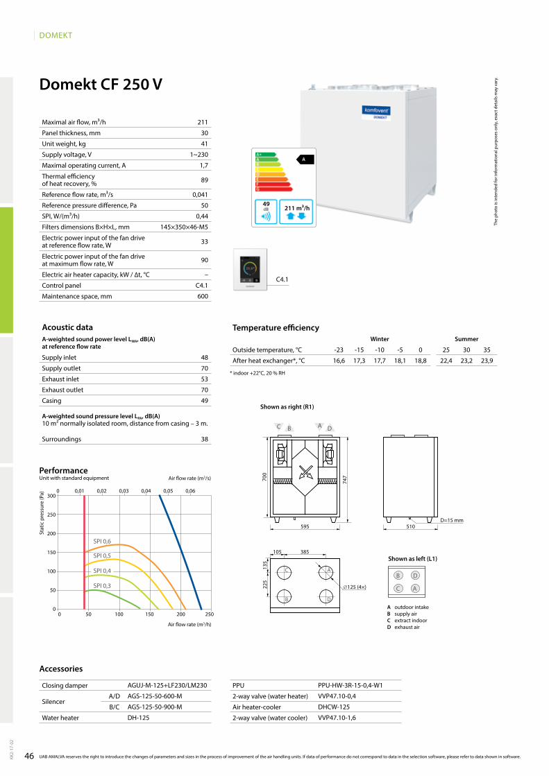
46
DOMEKT
A
211 m³/h49
A D
700
747
595D=15 mm
510
C B
A
105 385
135
225
C
B D
∅125 (4×)
D
AC
B
48
70
53
70
49
38
Domekt CF 250 V
211
30
41
1~230
1,7
89
0,041
50
0,44
145×350×46-M5
33
90
–
C4.1
600
C4.1
16,6 17,3 17,7 18,1 18,8 22,4 23,2 23,9
AgUJ-M-125+lF230/lM230
AgS-125-50-600-M
AgS-125-50-900-M
DH-125
PPU-HW-3R-15-0,4-W1
VVP47.10-0,4
DHCW-125
VVP47.10-1,6
KK2-
17-0
2
The
phot
o is
inte
nded
for i
nfor
mat
iona
l pur
pose
s on
ly, e
xact
det
ails
may
var
y.
Acoustic dataA-weighted sound power level LwA, dB(A)at reference flow rate
Supply inlet
Supply outlet
Exhaust inlet
Exhaust outlet
Casing
A-weighted sound pressure level LPA, dB(A) 10 m² normally isolated room, distance from casing – 3 m.
Surroundings
Maximal air flow, m³/h
Panel thickness, mm
Unit weight, kg
Supply voltage, V
Maximal operating current, A
Thermal efficiency of heat recovery, %
Reference flow rate, m³/s
Reference pressure difference, Pa
SPI, W/(m³/h)
Filters dimensions B×H×L, mm
Electric power input of the fan drive at reference flow rate, W
Electric power input of the fan drive at maximum flow rate, W
Electric air heater capacity, kW / ∆t, °C
Control panel
Maintenance space, mm
Stat
ic p
ress
ure
(Pa)
Air flow rate (m3/s)
Air flow rate (m3/h)
PerformanceUnit with standard equipment
UAB AMALVA reserves the right to introduce the changes of parameters and sizes in the process of improvement of the air handling units. If data of performance do not correspond to data in the selection software, please refer to data shown in software.
Temperature efficiencywinter Summer
Outside temperature, °C -23 -15 -10 -5 0 25 30 35
After heat exchanger*, °C
* indoor +22°C, 20 % RH
Accessories
Closing damper
SilencerA/D
B/C
Water heater
PPU
2-way valve (water heater)
Air heater-cooler
2-way valve (water cooler)
A outdoor intakeB supply airC extract indoorD exhaust air
Shown as left (L1)
Shown as right (R1)
0 0,01 0,02 0,03 0,04 0,05 0,06300
250
200
150
100
50
00 50 100 150 200 250
SPI 0,4
SPI 0,5
SPI 0,6
SPI 0,3
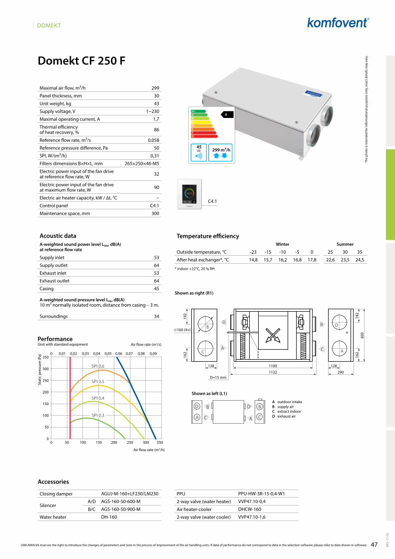
47
DOMEKT
Domekt CF 250 F
A
299 m³/h45
299
30
43
1~230
1,7
86
0,058
50
0,31
265×250×46-M5
32
90
–
C4.1
300
53
64
53
64
45
34
1100
1132 290
192
162
B D
AC
128 128
C
D
A
B
C
B D
A A
B
C
D
162
600
142
∅160 (4×)
D=15 mm
C4.1
14,8 15,7 16,2 16,8 17,8 22,6 23,5 24,5
AgUJ-M-160+lF230/lM230
AgS-160-50-600-M
AgS-160-50-900-M
DH-160
PPU-HW-3R-15-0,4-W1
VVP47.10-0,4
DHCW-160
VVP47.10-1,6
0 0,01 0,02 0,03 0,04 0,05 0,06 0,07 0,08 0,09350
300
250
200
150
100
50
00 50 100 150 200 250 300 350
SPI 0,4
SPI 0,5
SPI 0,6
SPI 0,3
KK2-
17-0
2
UAB AMALVA reserves the right to introduce the changes of parameters and sizes in the process of improvement of the air handling units. If data of performance do not correspond to data in the selection software, please refer to data shown in software.
The
phot
o is
inte
nded
for i
nfor
mat
iona
l pur
pose
s on
ly, e
xact
det
ails
may
var
y.
Acoustic dataA-weighted sound power level LwA, dB(A)at reference flow rate
Supply inlet
Supply outlet
Exhaust inlet
Exhaust outlet
Casing
A-weighted sound pressure level LPA, dB(A) 10 m² normally isolated room, distance from casing – 3 m.
Surroundings
Maximal air flow, m³/h
Panel thickness, mm
Unit weight, kg
Supply voltage, V
Maximal operating current, A
Thermal efficiency of heat recovery, %
Reference flow rate, m³/s
Reference pressure difference, Pa
SPI, W/(m³/h)
Filters dimensions B×H×L, mm
Electric power input of the fan drive at reference flow rate, W
Electric power input of the fan drive at maximum flow rate, W
Electric air heater capacity, kW / ∆t, °C
Control panel
Maintenance space, mm
Stat
ic p
ress
ure
(Pa)
Air flow rate (m3/s)
Air flow rate (m3/h)
PerformanceUnit with standard equipment
Temperature efficiencyWinter Summer
Outside temperature, °C -23 -15 -10 -5 0 25 30 35
After heat exchanger*, °C
* indoor +22°C, 20 % RH
Accessories
Closing damper
SilencerA/D
B/C
Water heater
PPU
2-way valve (water heater)
Air heater-cooler
2-way valve (water cooler)
Shown as left (L1)
Shown as right (R1)
A outdoor intakeB supply airC extract indoorD exhaust air

48
DOMEKT
AgUJ-M-160+lF230/lM230
AgS-160-50-600-M
AgS-160-50-900-M
DH-160
PPU-HW-3R-15-0,4-W1
VVP47.10-0,4
DHCW-160
VVP47.10-1,6
C6.1 C6.2
A
299 m³/h45
16,5 17 17,3 17,8 18,5 22,5 23,4 24,3
299
30
43
1~230
1,7
86
0,06
50
0,32
265×250×46-M5
32
90
0,5 / 6,4
1 / 12,8
C6.1 / 6.2
300
53
64
56
64
45
34
0 0,01 0,02 0,03 0,04 0,05 0,06 0,07 0,08 0,09350
300
250
200
150
100
50
00 50 100 150 200 250 300 350
SPI 0,4
SPI 0,5
SPI 0,6
SPI 0,3
1252
1282 295
192
162
B D
AC
128 128
C
D
A
B
C
B D
A A
B
C
D
162
605
142
160 (4×)
D=15 mm
Domekt CF 250 F
KK2-
17-0
2
The
phot
o is
inte
nded
for i
nfor
mat
iona
l pur
pose
s on
ly, e
xact
det
ails
may
var
y.
Acoustic dataA-weighted sound power level LwA, dB(A)at reference flow rate
Supply inlet
Supply outlet
Exhaust inlet
Exhaust outlet
Casing
A-weighted sound pressure level LPA, dB(A) 10 m² normally isolated room, distance from casing – 3 m.
Surroundings
Maximal air flow, m³/h
Panel thickness, mm
Unit weight, kg
Supply voltage, V
Maximal operating current, A
Thermal efficiency of heat recovery, %
Reference flow rate, m³/s
Reference pressure difference, Pa
SPI, W/(m³/h)
Filters dimensions B×H×L, mm
Electric power input of the fan drive at reference flow rate, W
Electric power input of the fan drive at maximum flow rate, W
Electric air heater capacity, kW / ∆t, °C
Electric preheater capacity, kW / ∆t, °C
Control panel
Maintenance space, mm
Stat
ic p
ress
ure
(Pa)
Air flow rate (m3/s)
Air flow rate (m3/h)
PerformanceUnit with standard equipment
UAB AMALVA reserves the right to introduce the changes of parameters and sizes in the process of improvement of the air handling units. If data of performance do not correspond to data in the selection software, please refer to data shown in software.
Temperature efficiencywinter Summer
Outside temperature, °C -23 -15 -10 -5 0 25 30 35
After heat exchanger*, °C
* indoor +22°C, 20 % RH
Accessories
Closing damper
SilencerA/D
B/C
Water heater
PPU
2-way valve (water heater)
Air heater-cooler
2-way valve (water cooler)
Shown as left (L1)
Shown as right (R1)
A outdoor intakeB supply airC extract indoorD exhaust air
PRELIMINARY
DATA
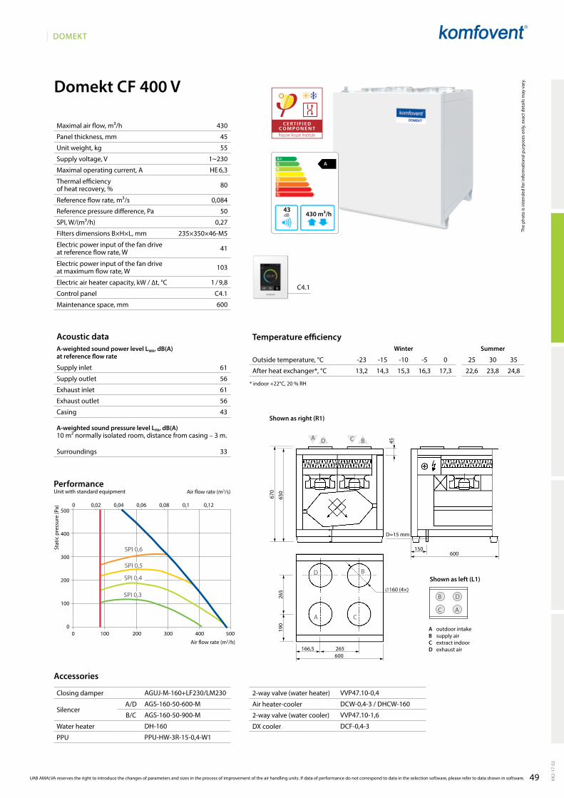
49
DOMEKT
Domekt CF 400 V
A
430 m³/h43
430
45
55
1~230
HE 6,3
80
0,084
50
0,27
235×350×46-M5
41
103
1 / 9,8
C4.1
600
61
56
61
56
43
33
A D
BD
C
650
670
∅160 (4×)
A
600
265166,5
190
265
C B
600
45
150
D
AC
B
D=15 mm
C4.1
13,2 14,3 15,3 16,3 17,3 22,6 23,8 24,8
AgUJ-M-160+lF230/lM230
AgS-160-50-600-M
AgS-160-50-900-M
DH-160
PPU-HW-3R-15-0,4-W1
VVP47.10-0,4
DCW-0,4-3 / DHCW-160
VVP47.10-1,6
DCF-0,4-3
0 100 200 300 400 500
500
400
300
200
100
0
0 0,02 0,04 0,06 0,08 0,1 0,12
SPI 0,4
SPI 0,5
SPI 0,6
SPI 0,3
KK2-
17-0
2
UAB AMALVA reserves the right to introduce the changes of parameters and sizes in the process of improvement of the air handling units. If data of performance do not correspond to data in the selection software, please refer to data shown in software.
The
phot
o is
inte
nded
for i
nfor
mat
iona
l pur
pose
s on
ly, e
xact
det
ails
may
var
y.
Acoustic dataA-weighted sound power level LwA, dB(A)at reference flow rate
Supply inlet
Supply outlet
Exhaust inlet
Exhaust outlet
Casing
A-weighted sound pressure level LPA, dB(A) 10 m² normally isolated room, distance from casing – 3 m.
Surroundings
Maximal air flow, m³/h
Panel thickness, mm
Unit weight, kg
Supply voltage, V
Maximal operating current, A
Thermal efficiency of heat recovery, %
Reference flow rate, m³/s
Reference pressure difference, Pa
SPI, W/(m³/h)
Filters dimensions B×H×L, mm
Electric power input of the fan drive at reference flow rate, W
Electric power input of the fan drive at maximum flow rate, W
Electric air heater capacity, kW / ∆t, °C
Control panel
Maintenance space, mm
Stat
ic p
ress
ure
(Pa)
Air flow rate (m3/s)
Air flow rate (m3/h)
PerformanceUnit with standard equipment
Temperature efficiencyWinter Summer
Outside temperature, °C -23 -15 -10 -5 0 25 30 35
After heat exchanger*, °C
* indoor +22°C, 20 % RH
Accessories
Closing damper
SilencerA/D
B/C
Water heater
PPU
2-way valve (water heater)
Air heater-cooler
2-way valve (water cooler)
DX cooler
Cooling unit
A outdoor intakeB supply airC extract indoorD exhaust air
Shown as left (L1)
Shown as right (R1)
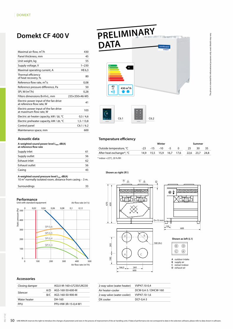
50
DOMEKT
AgUJ-M-160+lF230/lM230
AgS-160-50-600-M
AgS-160-50-900-M
DH-160
PPU-HW-3R-15-0,4-W1
VVP47.10-0,4
DCW-0,4-3 / DHCW-160
VVP47.10-1,6
DCF-0,4-3
A D
BD
C
650
670
160 (4×)
A
600
265166,5
190
265
C B
600
45
150
D
AC
B
D=15 mm
A
430 m³/h43
C6.1 C6.2
0 100 200 300 400 500
500
400
300
200
100
0
0 0,02 0,04 0,06 0,08 0,1 0,12
SPI 0,4
SPI 0,5
SPI 0,6
SPI 0,3
430
45
55
1~230
HE 6,3
80
0,08
50
0,28
235×350×46-M5
41
103
0,5 / 4,6
1,5 / 13,8
C6.1 / 6.2
600
Domekt CF 400 V
KK2-
17-0
2
The
phot
o is
inte
nded
for i
nfor
mat
iona
l pur
pose
s on
ly, e
xact
det
ails
may
var
y.
Acoustic dataA-weighted sound power level LwA, dB(A)at reference flow rate
Supply inlet
Supply outlet
Exhaust inlet
Exhaust outlet
Casing
A-weighted sound pressure level LPA, dB(A) 10 m² normally isolated room, distance from casing – 3 m.
Surroundings
Stat
ic p
ress
ure
(Pa)
Air flow rate (m3/s)
Air flow rate (m3/h)
PerformanceUnit with standard equipment
UAB AMALVA reserves the right to introduce the changes of parameters and sizes in the process of improvement of the air handling units. If data of performance do not correspond to data in the selection software, please refer to data shown in software.
Temperature efficiencywinter Summer
Outside temperature, °C -23 -15 -10 -5 0 25 30 35
After heat exchanger*, °C
* indoor +22°C, 20 % RH
Accessories
Closing damper
SilencerA/D
B/C
Water heater
PPU
2-way valve (water heater)
Air heater-cooler
2-way valve (water cooler)
DX cooler
Cooling unit
Maximal air flow, m³/h
Panel thickness, mm
Unit weight, kg
Supply voltage, V
Maximal operating current, A
Thermal efficiency of heat recovery, %
Reference flow rate, m³/s
Reference pressure difference, Pa
SPI, W/(m³/h)
Filters dimensions B×H×L, mm
Electric power input of the fan drive at reference flow rate, W
Electric power input of the fan drive at maximum flow rate, W
Electric air heater capacity, kW / ∆t, °C
Electric preheater capacity, kW / ∆t, °C
Control panel
Maintenance space, mm
61
56
62
56
43
33
14,9 15,5 15,9 16,7 17,6 22,6 23,7 24,8
A outdoor intakeB supply airC extract indoorD exhaust air
Shown as left (L1)
Shown as right (R1)
PRELIMINARY
DATA
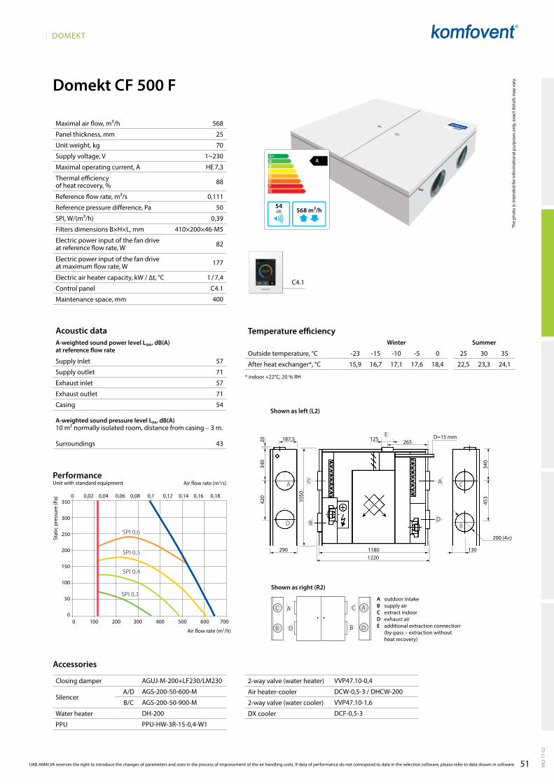
51
DOMEKT
Domekt CF 500 F
265E
11801220
125187,5
C
B
1050
420
340
20
A
D
A
D
C
B
130
453
340
290
D
A C
B D
A
B
C
A
568 m³/h54
568
25
70
1~230
HE 7,3
88
0,111
50
0,39
410×200×46-M5
82
177
1 / 7,4
C4.1
400
57
71
57
71
54
43
200 (4×)
D=15 mm
15,9 16,7 17,1 17,6 18,4 22,5 23,3 24,1
C4.1
AgUJ-M-200+lF230/lM230
AgS-200-50-600-M
AgS-200-50-900-M
DH-200
PPU-HW-3R-15-0,4-W1
VVP47.10-0,4
DCW-0,5-3 / DHCW-200
VVP47.10-1,6
DCF-0,5-3
0 100 200 300 400 500 600 700
350
300
250
200
150
100
50
0
0 0,02 0,04 0,06 0,08 0,1 0,12 0,14 0,16 0,18
SPI 0,4
SPI 0,5
SPI 0,6
SPI 0,3
KK2-
17-0
2
UAB AMALVA reserves the right to introduce the changes of parameters and sizes in the process of improvement of the air handling units. If data of performance do not correspond to data in the selection software, please refer to data shown in software.
The
phot
o is
inte
nded
for i
nfor
mat
iona
l pur
pose
s on
ly, e
xact
det
ails
may
var
y.
Acoustic dataA-weighted sound power level LwA, dB(A)at reference flow rate
Supply inlet
Supply outlet
Exhaust inlet
Exhaust outlet
Casing
A-weighted sound pressure level LPA, dB(A) 10 m² normally isolated room, distance from casing – 3 m.
Surroundings
Maximal air flow, m³/h
Panel thickness, mm
Unit weight, kg
Supply voltage, V
Maximal operating current, A
Thermal efficiency of heat recovery, %
Reference flow rate, m³/s
Reference pressure difference, Pa
SPI, W/(m³/h)
Filters dimensions B×H×L, mm
Electric power input of the fan drive at reference flow rate, W
Electric power input of the fan drive at maximum flow rate, W
Electric air heater capacity, kW / ∆t, °C
Control panel
Maintenance space, mm
Stat
ic p
ress
ure
(Pa)
Air flow rate (m3/s)
Air flow rate (m3/h)
PerformanceUnit with standard equipment
Temperature efficiencyWinter Summer
Outside temperature, °C -23 -15 -10 -5 0 25 30 35
After heat exchanger*, °C
* indoor +22°C, 20 % RH
Accessories
Closing damper
SilencerA/D
B/C
Water heater
PPU
2-way valve (water heater)
Air heater-cooler
2-way valve (water cooler)
DX cooler
Cooling unit
A outdoor intakeB supply airC extract indoorD exhaust airE additional extraction connection
(by-pass – extraction without heat recovery)
Shown as left (L2)
Shown as right (R2)
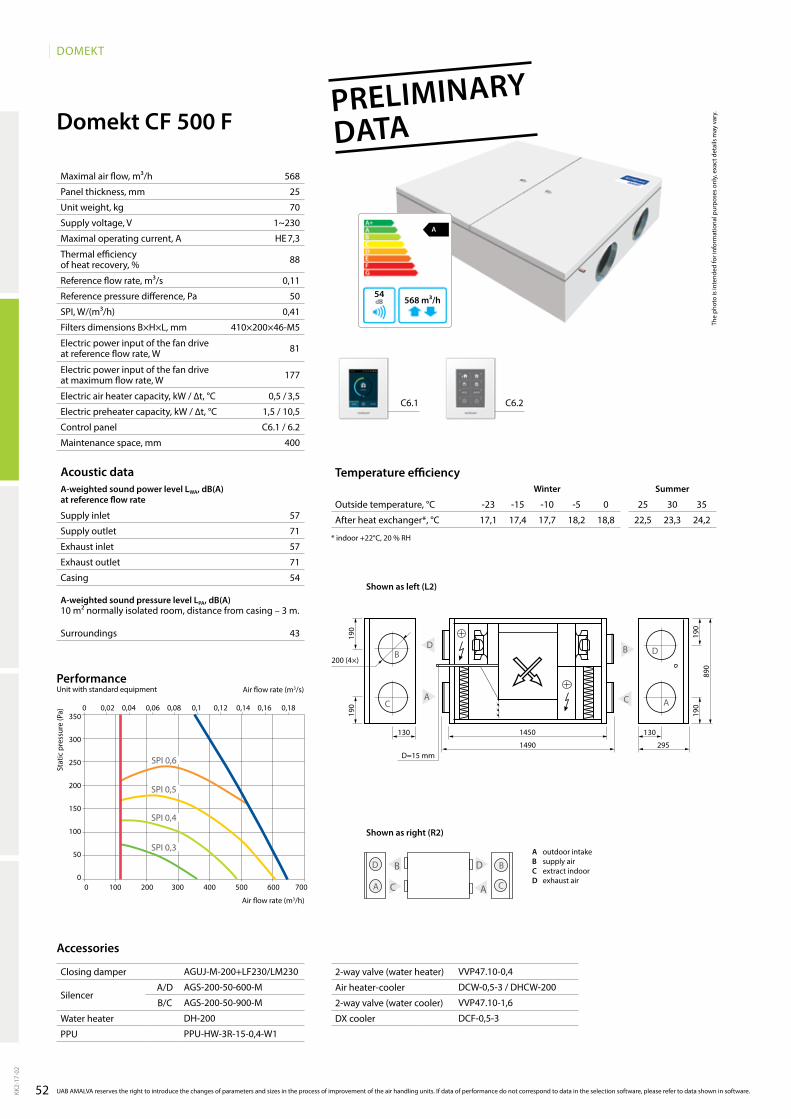
52
DOMEKT
A
568 m³/h54
568
25
70
1~230
HE 7,3
88
0,11
50
0,41
410×200×46-M5
81
177
0,5 / 3,5
1,5 / 10,5
C6.1 / 6.2
400
57
71
57
71
54
43
17,1 17,4 17,7 18,2 18,8 22,5 23,3 24,2
AgUJ-M-200+lF230/lM230
AgS-200-50-600-M
AgS-200-50-900-M
DH-200
PPU-HW-3R-15-0,4-W1
VVP47.10-0,4
DCW-0,5-3 / DHCW-200
VVP47.10-1,6
DCF-0,5-3
C6.1 C6.2
0 100 200 300 400 500 600 700
350
300
250
200
150
100
50
0
0 0,02 0,04 0,06 0,08 0,1 0,12 0,14 0,16 0,18
SPI 0,4
SPI 0,5
SPI 0,6
SPI 0,3
Domekt CF 500 F
1450
1490 295
190
190
B D
AC
130 130
C
D
A
B
C
B D
A A
B
C
D
190
890
190
200 (4×)
D=15 mm
KK2-
17-0
2
The
phot
o is
inte
nded
for i
nfor
mat
iona
l pur
pose
s on
ly, e
xact
det
ails
may
var
y.
Acoustic dataA-weighted sound power level LwA, dB(A)at reference flow rate
Supply inlet
Supply outlet
Exhaust inlet
Exhaust outlet
Casing
A-weighted sound pressure level LPA, dB(A) 10 m² normally isolated room, distance from casing – 3 m.
Surroundings
Stat
ic p
ress
ure
(Pa)
Air flow rate (m3/s)
Air flow rate (m3/h)
PerformanceUnit with standard equipment
UAB AMALVA reserves the right to introduce the changes of parameters and sizes in the process of improvement of the air handling units. If data of performance do not correspond to data in the selection software, please refer to data shown in software.
Temperature efficiencywinter Summer
Outside temperature, °C -23 -15 -10 -5 0 25 30 35
After heat exchanger*, °C
* indoor +22°C, 20 % RH
Accessories
Closing damper
SilencerA/D
B/C
Water heater
PPU
2-way valve (water heater)
Air heater-cooler
2-way valve (water cooler)
DX cooler
Cooling unit
Maximal air flow, m³/h
Panel thickness, mm
Unit weight, kg
Supply voltage, V
Maximal operating current, A
Thermal efficiency of heat recovery, %
Reference flow rate, m³/s
Reference pressure difference, Pa
SPI, W/(m³/h)
Filters dimensions B×H×L, mm
Electric power input of the fan drive at reference flow rate, W
Electric power input of the fan drive at maximum flow rate, W
Electric air heater capacity, kW / ∆t, °C
Electric preheater capacity, kW / ∆t, °C
Control panel
Maintenance space, mm
A outdoor intakeB supply airC extract indoorD exhaust air
Shown as left (L2)
Shown as right (R2)
PRELIMINARY
DATA
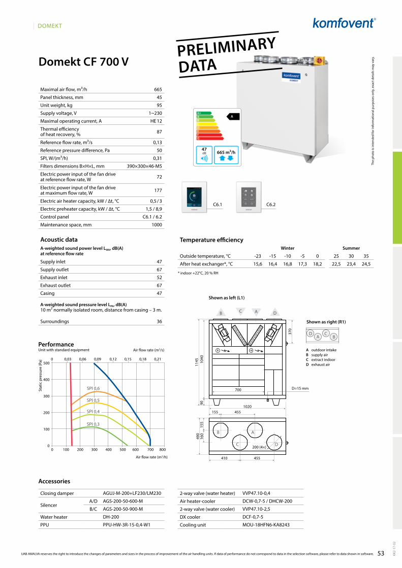
53
DOMEKT
A
665 m³/h47
665
45
95
1~230
HE 12
87
0,13
50
0,31
390×300×46-M5
72
177
0,5 / 3
1,5 / 8,9
C6.1 / 6.2
1000
47
67
52
67
47
36
D
A
С
B
490
700
1040
1145
90
370
155
160
1020155 455
455410
200 (4×)
D A
C B
A DCB
D=15 mm
15,6 16,4 16,8 17,3 18,2 22,5 23,4 24,5
AgUJ-M-200+lF230/lM230
AgS-200-50-600-M
AgS-200-50-900-M
DH-200
PPU-HW-3R-15-0,4-W1
VVP47.10-0,4
DCW-0,7-5 / DHCW-200
VVP47.10-2,5
DCF-0,7-5
MOU-18HFN6-KA8243
C6.1 C6.2
0 100 200 300 400 500 600 700 800
0 0,03 0,06 0,09 0,12 0,15 0,18 0,21500
400
300
200
100
0
SPI 0,4
SPI 0,5
SPI 0,6
SPI 0,3
Domekt CF 700 V
KK2-
17-0
2
UAB AMALVA reserves the right to introduce the changes of parameters and sizes in the process of improvement of the air handling units. If data of performance do not correspond to data in the selection software, please refer to data shown in software.
The
phot
o is
inte
nded
for i
nfor
mat
iona
l pur
pose
s on
ly, e
xact
det
ails
may
var
y.
Acoustic dataA-weighted sound power level LwA, dB(A)at reference flow rate
Supply inlet
Supply outlet
Exhaust inlet
Exhaust outlet
Casing
A-weighted sound pressure level LPA, dB(A) 10 m² normally isolated room, distance from casing – 3 m.
Surroundings
Stat
ic p
ress
ure
(Pa)
Air flow rate (m3/s)
Air flow rate (m3/h)
PerformanceUnit with standard equipment
Temperature efficiencyWinter Summer
Outside temperature, °C -23 -15 -10 -5 0 25 30 35
After heat exchanger*, °C
* indoor +22°C, 20 % RH
Accessories
Closing damper
SilencerA/D
B/C
Water heater
PPU
2-way valve (water heater)
Air heater-cooler
2-way valve (water cooler)
DX cooler
Cooling unit
Maximal air flow, m³/h
Panel thickness, mm
Unit weight, kg
Supply voltage, V
Maximal operating current, A
Thermal efficiency of heat recovery, %
Reference flow rate, m³/s
Reference pressure difference, Pa
SPI, W/(m³/h)
Filters dimensions B×H×L, mm
Electric power input of the fan drive at reference flow rate, W
Electric power input of the fan drive at maximum flow rate, W
Electric air heater capacity, kW / ∆t, °C
Electric preheater capacity, kW / ∆t, °C
Control panel
Maintenance space, mm
A outdoor intakeB supply airC extract indoorD exhaust air
Shown as right (R1)
Shown as left (L1)
PRELIMINARY
DATA

54
DOMEKT
Domekt CF 700 H
A
766 m³/h47
766
45
95
1~230
HE 12
85
0,15
50
0,3
390×300×46-M5
78
180
0,5 / 2,6
1,5 / 7,7
C6.1 / 6.2
500
47
67
52
67
47
36
1500
250 (4×)
245
200
300
4901540
700
90
C
D D
AA
B
B
A C
D
D=15 mm
14,8 15,7 16,1 16,8 17,8 22,5 23,5 24,6
AgUJ-M-250+lF230/lM230
AgS-250-50-600-M
AgS-250-50-900-M
DH-250
PPU-HW-3R-15-0,63-W1
VVP47.10-0,63
DCW-0,7-5 / DHCW-250
VVP47.10-2,5
DCF-0,7-5
MOU-18HFN6-KA8243
C6.1 C6.2
0 100 200 300 400 500 600 700 800 900
0 0,04 0,08 0,12 0,16 0,2 0,24500
400
300
200
100
0
SPI 0,4
SPI 0,5
SPI 0,6
SPI 0,3
KK2-
17-0
2
The
phot
o is
inte
nded
for i
nfor
mat
iona
l pur
pose
s on
ly, e
xact
det
ails
may
var
y.
Acoustic dataA-weighted sound power level LwA, dB(A)at reference flow rate
Supply inlet
Supply outlet
Exhaust inlet
Exhaust outlet
Casing
A-weighted sound pressure level LPA, dB(A) 10 m² normally isolated room, distance from casing – 3 m.
Surroundings
Stat
ic p
ress
ure
(Pa)
Air flow rate (m3/s)
Air flow rate (m3/h)
PerformanceUnit with standard equipment
UAB AMALVA reserves the right to introduce the changes of parameters and sizes in the process of improvement of the air handling units. If data of performance do not correspond to data in the selection software, please refer to data shown in software.
Temperature efficiencywinter Summer
Outside temperature, °C -23 -15 -10 -5 0 25 30 35
After heat exchanger*, °C
* indoor +22°C, 20 % RH
Accessories
Closing damper
SilencerA/D
B/C
Water heater
PPU
2-way valve (water heater)
Air heater-cooler
2-way valve (water cooler)
DX cooler
Cooling unit
Maximal air flow, m³/h
Panel thickness, mm
Unit weight, kg
Supply voltage, V
Maximal operating current, A
Thermal efficiency of heat recovery, %
Reference flow rate, m³/s
Reference pressure difference, Pa
SPI, W/(m³/h)
Filters dimensions B×H×L, mm
Electric power input of the fan drive at reference flow rate, W
Electric power input of the fan drive at maximum flow rate, W
Electric air heater capacity, kW / ∆t, °C
Electric preheater capacity, kW / ∆t, °C
Control panel
Maintenance space, mm
A outdoor intakeB supply airC extract indoorD exhaust air
Shown as right (R1)
Shown as left (L1)
PRELIMINARY
DATA

55
DOMEKT
Domekt CF 900 U / H / V
A+
1000 m³/h43
1000
50
267
HE 3~400 / HW 1~230
HE 9,8 / HW 3,3
82
0,194
50
0,17
800×400×46-M5
57
162
4,5/19,1
C5.1
49
64
49
64
43
33
B
A C
D
A C
B
C
A
D
D B
C5.1
0 200 400 600 800 1000 1200
0 0,05 0,1 0,15 0,2 0,25 0,3600
500
400
300
200
100
0
SPI 0,21
SPI 0,28
SPI 0,35
SPI 0,14
AgUJ-M-315+lF24/lM24
AgS-315-100-900-M
AgS-315-100-1200-M
PPU-HW-3R-15-1,0-W2
DCW-0,7-5
VVP47.15-2,5+SSP61
DCF-0,7-5
MOU-18HFN6-KA8243
242
1962
905
242
1810
C
D D
A A
B
253
980
905
430
253
108
253253
315 (4×)
A
C
B
259
910285 100
D=15 mm
2,7 2,7 2,7 2,7 3,8
117 117 116 116 644
1 1 1 1 6,8
14,1/22 23,6/18
21,5 16,5 11,4 6,5 6,4
½
14,1 15 15,9 16,8 17,8 22,6 23,6 24,6
KK2-
17-0
2
UAB AMALVA reserves the right to introduce the changes of parameters and sizes in the process of improvement of the air handling units. If data of performance do not correspond to data in the selection software, please refer to data shown in software.
Closing damper
SilencerA/D
B/C
PPU
Air heater-cooler
2-way valve
DX cooler
Cooling unit
The
phot
o is
inte
nded
for i
nfor
mat
iona
l pur
pose
s on
ly, e
xact
det
ails
may
var
y.
Acoustic dataA-weighted sound power level LwA, dB(A)at reference flow rate
Supply inlet
Supply outlet
Exhaust inlet
Exhaust outlet
Casing
A-weighted sound pressure level LPA, dB(A) 10 m² normally isolated room, distance from casing – 3 m.
Surroundings
Maximal air flow, m³/h
Panel thickness, mm
Unit weight, kg
Supply voltage, V
Maximal operating current, A
Thermal efficiency of heat recovery, %
Reference flow rate, m³/s
Reference pressure difference, Pa
SPI, W/(m³/h)
Filters dimensions B×H×L, mm
Electric power input of the fan drive at reference flow rate, W
Electric power input of the fan drive at maximum flow rate, W
Electric air heater capacity, kW / ∆t, °C
Control panel
Maintenance space, mm
Stat
ic p
ress
ure
(Pa)
Air flow rate (m3/s)
Air flow rate (m3/h)
PerformanceUnit with standard equipment
Temperature efficiencyWinter Summer
Outside temperature, °C -23 -15 -10 -5 0 25 30 35
After heat exchanger*, °C
* indoor +22°C, 20 % RH
Accessories
Changeover water heating/cooling exchanger (HCW)Winter Summer
Water temperature in/out, °C 90/70 80/60 70/50 60/40 7/12
Capacity, kW
Flow rate, dm³/h
Pressure drop, kPa
Temperature in/out, °C
Maximal capacity, kW
Connection, ”
Shown as right (R1)
Shown as left (L1)
A outdoor intakeB supply airC extract indoorD exhaust air
Available versions:1) Electric air heater (HE);2) Changeover water heating/cooling exchanger (HCW);3) Changeover water heating/cooling exchanger (HCW) and electric air heater (HE).

56
DOMEKT
Domekt CF 900 F
A+
1000 m³/h47
1000
50
161
HE 3~400 / HW 1~230
HE 9,8 / HW 3,3
82
0,194
50
0,17
550×420×46-M5
56
167
3 / 12,8
C5.1
400
54
68
54
68
47
36
16501795
263
550
275
B D
AC
527
C
D
A
B
C
B D
A A
B
C
D
1100
110
315 (4×)
D=15 mm
0 200 400 600 800 1000 1200
0 0,05 0,1 0,15 0,2 0,25 0,3600
500
400
300
200
100
0
SPI 0,35
SPI 0,21
SPI 0,14
14 15 15,9 16,8 17,8 22,6 23,6 24,6
C5.1
AgUJ-M-315+lF24/lM24
AgS-315-100-900-M
AgS-315-100-1200-M
DH-315
PPU-HW-3R-15-1,0-W2
DCW-0,9-6; DHCW-315
VVP47.15-2,5+SSP61
DCF-0,9-6
MOU-18HFN6-KA8243
SPI 0,28
KK2-
17-0
2
The
phot
o is
inte
nded
for i
nfor
mat
iona
l pur
pose
s on
ly, e
xact
det
ails
may
var
y.
Acoustic dataA-weighted sound power level LwA, dB(A)at reference flow rate
Supply inlet
Supply outlet
Exhaust inlet
Exhaust outlet
Casing
A-weighted sound pressure level LPA, dB(A) 10 m² normally isolated room, distance from casing – 3 m.
Surroundings
Maximal air flow, m³/h
Panel thickness, mm
Unit weight, kg
Supply voltage, V
Maximal operating current, A
Thermal efficiency of heat recovery, %
Reference flow rate, m³/s
Reference pressure difference, Pa
SPI, W/(m³/h)
Filters dimensions B×H×L, mm
Electric power input of the fan drive at reference flow rate, W
Electric power input of the fan drive at maximum flow rate, W
Electric air heater capacity, kW / ∆t, °C
Control panel
Maintenance space, mm
Stat
ic p
ress
ure
(Pa)
Air flow rate (m3/s)
Air flow rate (m3/h)
PerformanceUnit with standard equipment
UAB AMALVA reserves the right to introduce the changes of parameters and sizes in the process of improvement of the air handling units. If data of performance do not correspond to data in the selection software, please refer to data shown in software.
Temperature efficiencywinter Summer
Outside temperature, °C -23 -15 -10 -5 0 25 30 35
After heat exchanger*, °C
* indoor +22°C, 20 % RH
Accessories
Closing damper
SilencerA/D
B/C
Water heater
PPU
Air heater-cooler
2-way valve (water cooler)
DX cooler
Cooling unit
Shown as left (L1)
Shown as right (R1)
A outdoor intakeB supply airC extract indoorD exhaust air

57
DOMEKT
Domekt S
0 0,28 0,56 0,83 0,11 0,14 0,17 0,19 0,22 0,25 0,28
0 100 200 300 400 500 600 700 800 900 1000
1000
800
650
KK2-
17-0
2
False ceiling supply air handling units.
Advantages of Domekt S units
• Height is only 297 mm / 350 mm – easy to choose the place for installation.
• Units are complemented with fastening profiles and vib-ration absorbing holders.
• Safe and handy design of removable cover ensures easy fi xing of cover at different opening levels for perfor ming maintenance and service inspection.
• Air handling units have integrated control system.• Control panel may be installed in any user-convenient place.• Control panel display enables to set the operation
parameters of the unit and monitor them.• There is a possibility to complement and control the duct
mounted cooling section.
Duct connectionF – false ceiling.
Heater
HE – electric heater.
HW – water air heater.
HCW – heater-cooler one for both – heating and cooling. Ideal for buildings using geothermal energy.
Domekt S range
Cooler
CW – designed for air cooling using cold water (water-glycol mixture), provides a higher comfort level in rooms.
CDX – designed for air cooling using direct expansion cooling unit, provides a higher comfort level in rooms.
Inspection side
See p. 132.
Control system More information about C5 on p. 10.
Unit size Supply/exhaust air filter class Heater Cooler Inspection
sideC5
panel
M5 F7 HE HW HCW CW CDX R1 C5.1
Domekt S 650 F � � � � �
Domekt S 800 F � � � � � �
Domekt S 1000 F � � � � � �
� standard equipment� possible choice ordered separately
Air flow, m³/h
Air flow, m³/s
Standard sizes of Domekt S units

58
DOMEKT
Domekt S 650 F
B
642 m³/h41
642
50
35
0,125
50
0,15
235×371×46-M5
63
172
C5.1
300
63
69
41
30 Domekt S 650 F-HE/3 1~230 3,0 14,2 13
Domekt S 650 F-HE/6 3~400 6,0 10,0 26
C5.1
AgUJ-M-160+lF24/lM24
AgS-160-50-600-M
AgS-160-50-900-M
–
DCW-0,7-5
VVP47.15-2,5+SSP61
DCF-0,7-5
MOU-18HFN6+KA8243
873
475×
297
D=160 mm
500
400
300
200
100
00 100 200 300 400 500 600 700
0 0,03 0,06 0,09 0,12 0,15 0,18
SPI 0,2
SPI 0,3
SPI 0,4
SPI 0,1
KK2-
17-0
2
UAB AMALVA reserves the right to introduce the changes of parameters and sizes in the process of improvement of the air handling units. If data of performance do not correspond to data in the selection software, please refer to data shown in software.
Maximal air flow, m³/h
Panel thickness, mm
Unit weight, kg
Reference flow rate, m³/s
Reference pressure difference, Pa
SPI, W/(m³/h)
Filters dimensions B×H×L, mm
Electric power input of the fan drive at reference flow rate, W
Electric power input of the fan drive at maximum flow rate, W
Control panel
Maintenance space, mm
The
phot
o is
inte
nded
for i
nfor
mat
iona
l pur
pose
s on
ly, e
xact
det
ails
may
var
y.
Acoustic dataA-weighted sound power level LwA, dB(A)at reference flow rate
Supply inlet
Supply outlet
Casing
A-weighted sound pressure level LPA, dB(A) 10 m² normally isolated room, distance from casing – 3 m.
Surroundings
Stat
ic p
ress
ure
(Pa)
Air flow rate (m3/s)
Air flow rate (m3/h)
PerformanceUnit with standard equipment
Closing damper
SilencerA/D
B/C
PPU
Air heater-cooler
2-way valve
DX cooler
Cooling unit
Accessories
Technical data
Supply air handling unit
Supply voltage, V
Air heater capacity, kw
Maximal operating current, A
ΔT, °C

59
DOMEKT
Domekt S 800 F
60
66
44
33 Domekt S 800 F-HE/3 1~230 3,0 14,9 10
Domekt S 800 F-HE/6 3~400 6,0 10,6 20
Domekt S 800 F-HE/9 3~400 9,0 14,9 30
Domekt S 800 F-HW 1~230 – 1,9 –
973
475×
350
D=200 mm
826
50
37
0,161
50
0,14
287×371×46-M5
75
181
C5.1
400
B
826 m³/h44
C5.1
AgUJ-M-200+lF24/lM24
AgS-200-50-600-M
AgS-200-50-900-M
PPU-HW-3R-15-2,5-W2
DCW-0,9-6
VVP47.15-2,5+SSP61
DCF-0,9-6
MOU-18HFN6-KA8243
90/70 80/60 70/50 60/40
11,3 11,1 9,5 5,9
499 488 414 257
4,2 4,1 3,1 1,4
-23/20 -23/19,2 -23/13 -10/12,4
12,6 11,1 9,5 5,9
½
500
400
300
200
100
0
0 0,03 0,06 0,09 0,12 0,15 0,18 0,21 0,24
0 100 200 300 400 500 600 700 800 900
SPI 0,1
SPI 0,2
SPI 0,3
SPI 0,4
KK2-
17-0
2
UAB AMALVA reserves the right to introduce the changes of parameters and sizes in the process of improvement of the air handling units. If data of performance do not correspond to data in the selection software, please refer to data shown in software.
The
phot
o is
inte
nded
for i
nfor
mat
iona
l pur
pose
s on
ly, e
xact
det
ails
may
var
y.
Maximal air flow, m³/h
Panel thickness, mm
Unit weight, kg
Reference flow rate, m³/s
Reference pressure difference, Pa
SPI, W/(m³/h)
Filters dimensions B×H×L, mm
Electric power input of the fan drive at reference flow rate, W
Electric power input of the fan drive at maximum flow rate, W
Control panel
Maintenance space, mm
The
phot
o is
inte
nded
for i
nfor
mat
iona
l pur
pose
s on
ly, e
xact
det
ails
may
var
y.
Acoustic dataA-weighted sound power level LwA, dB(A)at reference flow rate
Supply inlet
Supply outlet
Casing
A-weighted sound pressure level LPA, dB(A) 10 m² normally isolated room, distance from casing – 3 m.
Surroundings
Stat
ic p
ress
ure
(Pa)
Air flow rate (m3/s)
Air flow rate (m3/h)
PerformanceUnit with standard equipment
Closing damper
SilencerA/D
B/C
PPU
Air heater-cooler
2-way valve
DX cooler
Cooling unit
Accessories
Hot water air heaterWater temperature in/out, °C
Capacity, kW
Flow rate, dm³/h
Pressure drop, kPa
Temperature in/out, °C
Maximal capacity, kW
Connection, ”
Technical data
Supply air handling unit
Supply voltage, V
Air heater capacity, kW
Maximal operating current, A
ΔT, °C
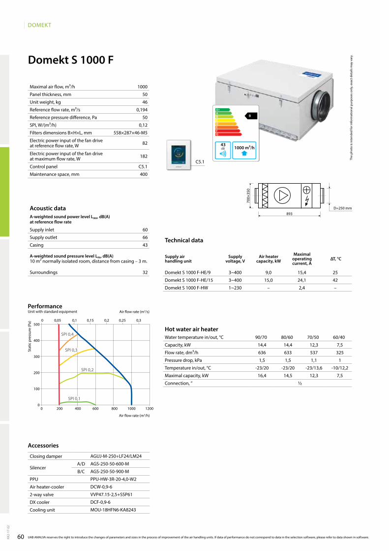
60
DOMEKT
1000
50
46
0,194
50
0,12
558×287×46-M5
82
182
C5.1
400
B
642 m³/h41
C5.1
AgUJ-M-250+lF24/lM24
AgS-250-50-600-M
AgS-250-50-900-M
PPU-HW-3R-20-4,0-W2
DCW-0,9-6
VVP47.15-2,5+SSP61
DCF-0,9-6
MOU-18HFN6-KA8243
Domekt S 1000 F
60
66
43
32
1000 m³/h43
B
90/70 80/60 70/50 60/40
14,4 14,4 12,3 7,5
636 633 537 325
1,5 1,5 1,1 1
-23/20 -23/20 -23/13,6 -10/12,2
16,4 14,5 12,3 7,5
½
Domekt S 1000 F-HE/9 3~400 9,0 15,4 25
Domekt S 1000 F-HE/15 3~400 15,0 24,1 42
Domekt S 1000 F-HW 1~230 – 2,4 –
893
700×
350
D=250 mm
0 200 400 600 800 1000 1200
0 0,05 0,1 0,15 0,2 0,25 0,3500
400
300
200
100
0
SPI 0,2
SPI 0,3
SPI 0,4
SPI 0,1
KK2-
17-0
2
UAB AMALVA reserves the right to introduce the changes of parameters and sizes in the process of improvement of the air handling units. If data of performance do not correspond to data in the selection software, please refer to data shown in software.
Maximal air flow, m³/h
Panel thickness, mm
Unit weight, kg
Reference flow rate, m³/s
Reference pressure difference, Pa
SPI, W/(m³/h)
Filters dimensions B×H×L, mm
Electric power input of the fan drive at reference flow rate, W
Electric power input of the fan drive at maximum flow rate, W
Control panel
Maintenance space, mm
The
phot
o is
inte
nded
for i
nfor
mat
iona
l pur
pose
s on
ly, e
xact
det
ails
may
var
y.
Acoustic dataA-weighted sound power level LwA, dB(A)at reference flow rate
Supply inlet
Supply outlet
Casing
A-weighted sound pressure level LPA, dB(A) 10 m² normally isolated room, distance from casing – 3 m.
Surroundings
Stat
ic p
ress
ure
(Pa)
Air flow rate (m3/s)
Air flow rate (m3/h)
PerformanceUnit with standard equipment
Closing damper
SilencerA/D
B/C
PPU
Air heater-cooler
2-way valve
DX cooler
Cooling unit
Accessories
Hot water air heaterWater temperature in/out, °C
Capacity, kW
Flow rate, dm³/h
Pressure drop, kPa
Temperature in/out, °C
Maximal capacity, kW
Connection, ”
Technical data
Supply air handling unit
Supply voltage, V
Air heater capacity, kw
Maximal operating current, A
ΔT, °C

VERSONon residential ventilation units
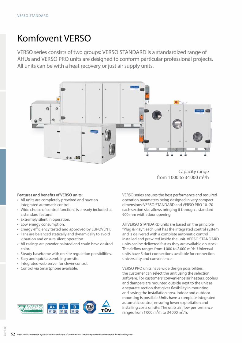
62
VERSO StandaRd
AHU N˚: 07.09.356Range: VERSO
Komfovent VERSO
UAB AMALVA reserves the right to introduce the changes of parameters and sizes in the process of improvement of the air handling units.KK2-
17-0
2
VERSO series consists of two groups: VERSO StaNdaRd is a standardized range of aHUs and VERSO PRO units are designed to conform particular professional projects. all units can be with a heat recovery or just air supply units.
VERSO series ensures the best performance and required operation parameters being designed in very compact dimensions: VERSO StaNdaRd and VERSO PRO 10–70 each section size allows bringing it through a standard 900 mm width door opening.
all VERSO StaNdaRd units are based on the principle "Plug & Play": each unit has the integrated control system and is delivered with a complete automatic control installed and prewired inside the unit. VERSO StaNdaRd units can be delivered fast as they are avai lable on stock. the airflow ranges from 1 000 to 8 000 m³/h. Universal units have 8 duct connections available for connection universality and convenience.
VERSO PRO units have wide design possibilities, the customer can select the unit using the selection software. For customers’ convenience air heaters, coolers and dampers are mounted outside next to the unit as a separate section that gives flexibility in mounting and saving the installation area. Indoor and outdoor mounting is possible. Units have a complete integrated automatic control, ensuring lower exploitation and installing costs on site. the units air flow performance ranges from 1 000 m³/h to 34 000 m³/h.
Features and benefits of VERSO units: • all units are completely prewired and have an
integrated automatic control.• Wide choice of control functions is already included as
a standard feature.• Extremely silent in operation.• Low energy consumption.• Energy efficiency tested and approved by EUROVENt.• Fans are balanced statically and dynamically to avoid
vibra tion and ensure silent operation.• all casings are powder painted and could have desired
color.• Steady baseframe with on-site regulation possibilities.• Easy and quick assembling on-site.• Integrated web server for clever control.• Control via Smartphone available.
Capacity range from 1 000 to 34 000 m3/h
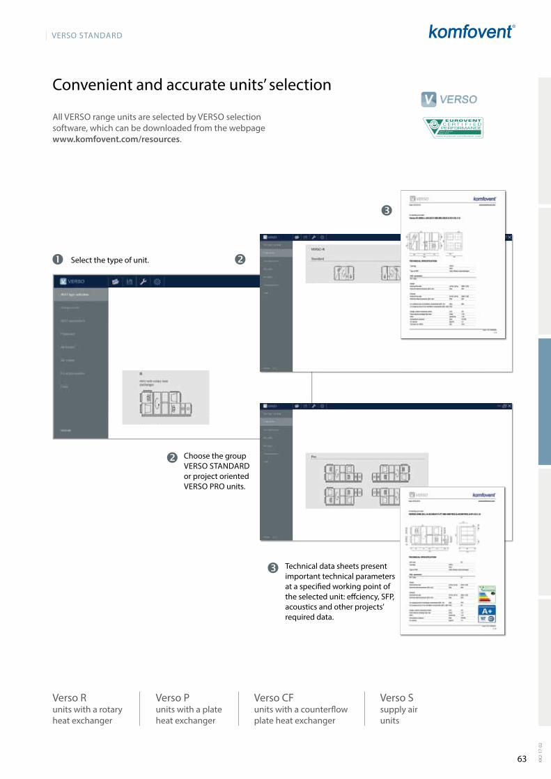
63
VERSO StandaRd
AHU N˚: 07.09.356Range: VERSO
KK2-
17-0
2
Convenient and accurate units’ selection
all VERSO range units are selected by VERSO selection software, which can be downloaded from the webpage www.komfovent.com/resources.
technical data sheets present important technical parameters at a specified working point of the selected unit: effciency, SFP, acoustics and other projects’ required data.
Choose the group VERSO StaNdaRd or project oriented VERSO PRO units.
Select the type of unit.
Verso P units with a pla te he at ex chan ger
Verso R units with a ro ta ry he at ex chan ger
Verso CF units with a counterflow plate heat exchanger
Verso S sup ply air units
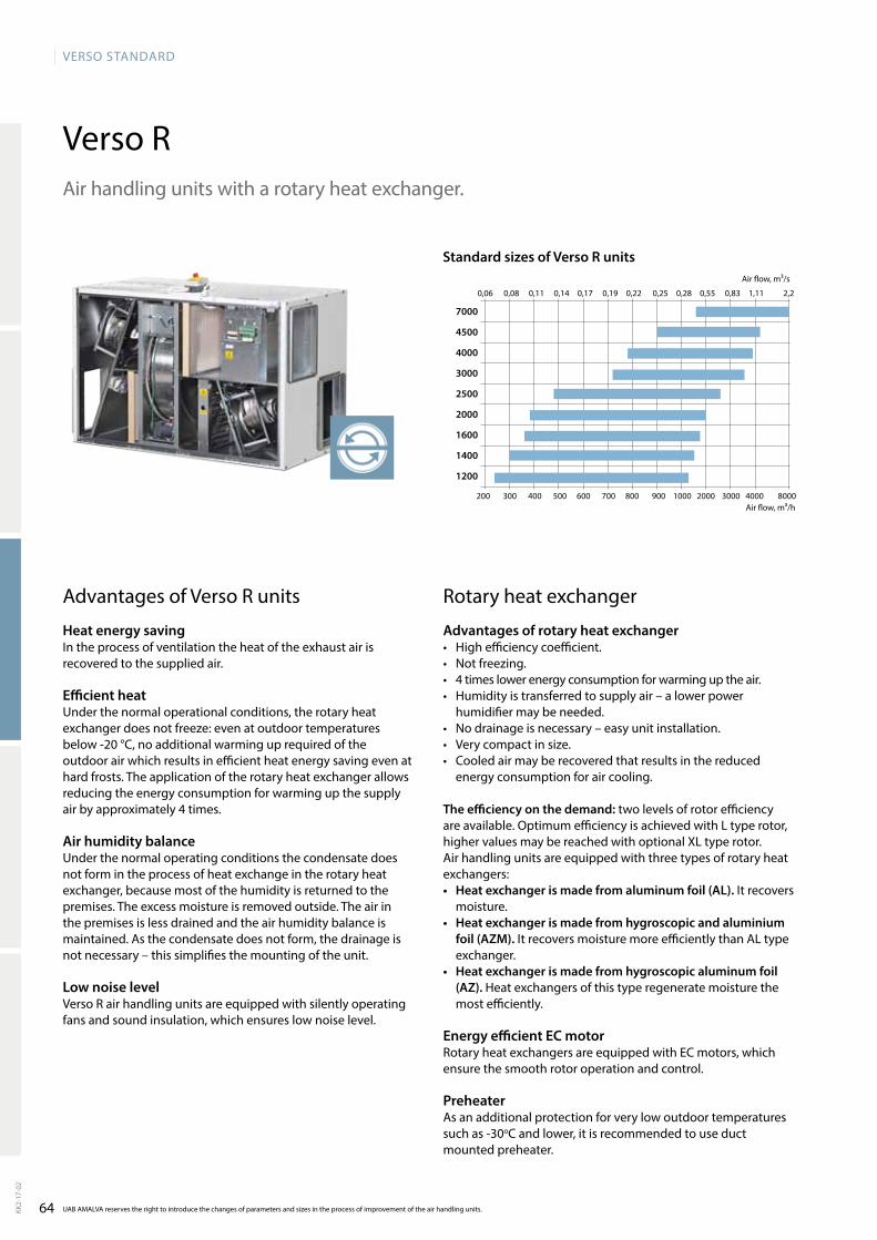
64
VERSO StandaRd
Verso R
200 300 400 500 600 700 800 900 1000 2000 3000 4000 8000
0,06 0,08 0,11 0,14 0,17 0,19 0,22 0,25 0,28 0,55 0,83 1,11 2,2
7000
4500
4000
3000
2500
2000
1600
1400
1200
UAB AMALVA reserves the right to introduce the changes of parameters and sizes in the process of improvement of the air handling units.KK2-
17-0
2
air handling units with a rotary heat exchanger.
advantages of Verso R units
Heat energy saving In the process of ventilation the heat of the exhaust air is recovered to the supplied air.
Efficient heat Under the normal operational conditions, the rotary heat exchanger does not freeze: even at outdoor tempe ratures below -20 °C, no additional warming up required of the outdoor air which results in efficient heat energy saving even at hard frosts. the application of the rotary heat exchanger allows reducing the energy consumption for warming up the supply air by approximately 4 times.
Air humidity balanceUnder the normal operating conditions the condensate does not form in the process of heat exchange in the rotary heat exchanger, because most of the humidity is returned to the premises. the excess moisture is removed outside. the air in the premises is less drained and the air humidity balance is maintained. as the condensate does not form, the drainage is not necessary – this simplifies the mounting of the unit.
Low noise levelVerso R air handling units are equipped with silently ope rating fans and sound insulation, which ensures low noise level.
Rotary heat exchanger
Advantages of rotary heat exchanger• High efficiency coefficient.• Not freezing.• 4 times lower energy consumption for warming up the air. • Humidity is transferred to supply air – a lower power
humidifier may be needed.• No drainage is necessary – easy unit installation.• Very compact in size.• Cooled air may be recovered that results in the reduced
energy consumption for air cooling.
The efficiency on the demand: two levels of rotor efficiency are available. Optimum efficiency is achieved with L type rotor, higher values may be reached with optional XL type rotor.air handling units are equipped with three types of rotary heat exchangers:• Heat exchanger is made from aluminum foil (AL). It recovers
moisture.• Heat exchanger is made from hygroscopic and aluminium
foil (AZM). It recovers moisture more efficiently than aL type exchanger.
• Heat exchanger is made from hygroscopic aluminum foil (AZ). Heat exchan gers of this type regene rate moisture the most efficiently.
Energy efficient EC motorRotary heat exchangers are equipped with EC motors, which ensure the smooth rotor ope ration and control.
Preheateras an additional protection for very low outdoor temperatures such as -30oC and lower, it is recommended to use duct mounted preheater.
Standard sizes of Verso R units
air flow, m³/h
air flow, m³/s
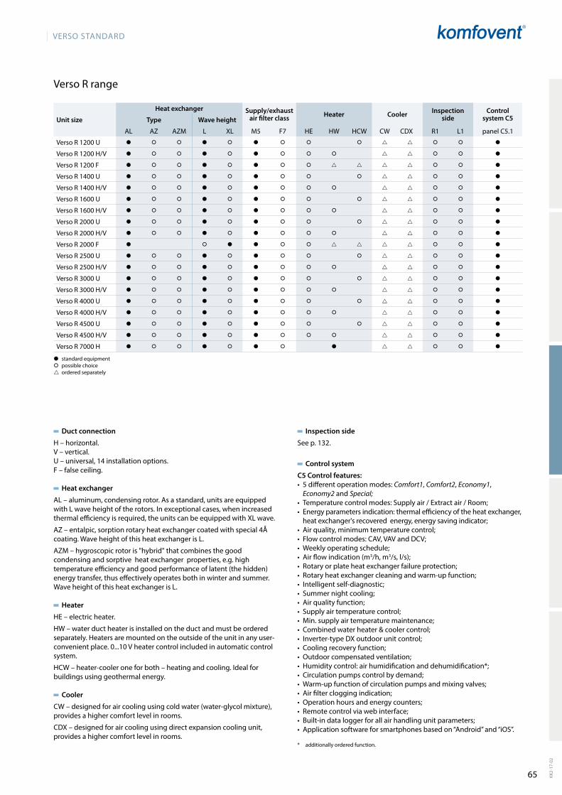
65
VERSO StandaRd
KK2-
17-0
2
Verso R range
Duct connection
H – horizontal.V – vertical.U – universal, 14 installation options.F – false ceiling.
Heat exchanger
aL – aluminum, condensing rotor. as a standard, units are equipped with L wave height of the rotors. In exceptional cases, when increased thermal efficiency is required, the units can be equipped with XL wave.
aZ – entalpic, sorption rotary heat exchanger coated with special 4Å coating. Wave height of this heat exchanger is L.
aZM – hygroscopic rotor is "hybrid" that combines the good condensing and sorptive heat exchanger properties, e.g. high temperature efficiency and good performance of latent (the hidden) energy transfer, thus effectively operates both in winter and summer.Wave height of this heat exchanger is L.
Heater
HE – electric heater.
HW – water duct heater is installed on the duct and must be ordered separately. Heaters are mounted on the outside of the unit in any user-convenient place. 0...10 V heater control included in automatic control system.
HCW – heater-cooler one for both – heating and cooling. Ideal for buildings using geothermal energy.
Cooler
CW – designed for air cooling using cold water (water-glycol mixture), provides a higher comfort level in rooms.
CdX – designed for air cooling using direct expansion cooling unit, provides a higher comfort level in rooms.
� standard equipment� possible choice ordered separately
Unit size
Heat exchanger Supply/exhaust air filter class Heater Cooler Inspection
sideControl
system C5Type Wave height
aL aZ aZM L XL M5 F7 HE HW HCW CW CdX R1 L1 panel C5.1
Verso R 1200 U � � � � � � � � � � � �
Verso R 1200 H/V � � � � � � � � � � � �
Verso R 1200 F � � � � � � � � � � �
Verso R 1400 U � � � � � � � � � � � �
Verso R 1400 H/V � � � � � � � � � � � �
Verso R 1600 U � � � � � � � � � � � �
Verso R 1600 H/V � � � � � � � � � � � �
Verso R 2000 U � � � � � � � � � � � �
Verso R 2000 H/V � � � � � � � � � � � �
Verso R 2000 F � � � � � � � � �
Verso R 2500 U � � � � � � � � � � � �
Verso R 2500 H/V � � � � � � � � � � � �
Verso R 3000 U � � � � � � � � � � � �
Verso R 3000 H/V � � � � � � � � � � � �
Verso R 4000 U � � � � � � � � � � � �
Verso R 4000 H/V � � � � � � � � � � � �
Verso R 4500 U � � � � � � � � � � � �
Verso R 4500 H/V � � � � � � � � � � � �
Verso R 7000 H � � � � � � � � � � �
Inspection side
See p. 132.
Control system
C5 Control features:• 5differentoperationmodes:Comfort1, Comfort2, Economy1,
Economy2 and Special;• Temperaturecontrolmodes:Supplyair/Extractair/Room;• Energyparametersindication:thermalefficiencyoftheheatexchanger,heatexchanger'srecoveredenergy,energysavingindicator;
• Airquality,minimumtemperaturecontrol;• Flowcontrolmodes:CAV,VAVandDCV;• Weeklyoperatingschedule;• Airflowindication(m3/h, m3/s,l/s);• Rotaryorplateheatexchangerfailureprotection;• Rotaryheatexchangercleaningandwarm-upfunction;• Intelligentself-diagnostic;• Summernightcooling;• Airqualityfunction;• Supplyairtemperaturecontrol;• Min.supplyairtemperaturemaintenance;• Combinedwaterheater&coolercontrol;• Inverter-typeDXoutdoorunitcontrol;• Coolingrecoveryfunction;• Outdoorcompensatedventilation;• Humiditycontrol:airhumidificationanddehumidification*;• Circulationpumpscontrolbydemand;• Warm-upfunctionofcirculationpumpsandmixingvalves;• Airfiltercloggingindication;• Operationhoursandenergycounters;• Remotecontrolviawebinterface;• Built-indataloggerforallairhandlingunitparameters;• Applicationsoftwareforsmartphonesbasedon“Android”and“iOS”.
* additionallyorderedfunction.

66
VERSO StandaRd
Verso R 1200 U / H / V
1300
50
195
3~400
1~230
13,2
7,2
800×400×46-M5
470
4,5 / 9,6
C5.1
800
14,5 15,9 16,7 17,5 18,4 23,357
71
57
68
50
40
3,3 3,3 3,3 3,3 4,7
144 144 143 142 803
1 1 1 1 10,5
14,5/22 23,3/18
29,5 23,1 16,9 10,7 8,5
½
281252 372372
905905 13551505
905
905
247
247
412
412
С
B d
a
315 (4×)
315 (4×)
750
250
100
253
400
C
B
d
a
d=15 mm
C
a
d
B
B
d
a
C
C
C
a
a
B
B
d
d
250
aGUJ-M-315+LF24/LM24
aGS-315-100-900-M
aGS-315-100-1200-M
PPU-HW-3R-15-1,0-W2
dCW-1,2-8
VVP47.15-2,5+SSP61
dCF-1,2-8
MOU-24HFN6-Ka8243
SFP 1,25
SFP 0,5
SFP 1
SFP 0,75
600
500
400
300
200
100
00 300 600 900 1200 1500
0 0,05 0,1 0,15 0,2 0,25 0,3 0,35 0,4
C5.1
The
phot
o is
inte
nded
for i
nfor
mat
iona
l pur
pose
s on
ly, e
xact
det
ails
may
var
y.
Acoustic dataA-weighted sound power level LwA, dB(A)at nominal flow rate
Supply inlet
Supply outlet
Exhaust inlet
Exhaust outlet
Casing
A-weighted sound pressure level LPA, dB(A) 10 m² normally isolated room, distance from casing – 3 m.
Surroundings
Nominal air flow, m³/h
Panel thickness, mm
Unit weight, kg
Supply voltage HE, V
Supply voltage HW, V
Maximal operating current HE, A
Maximal operating current HW, A
Filters dimensions B×H×L, mm
Electric power input of the fan drive at maximum flow rate, W
Electric air heater capacity, kW / ∆t, °C
Control panel
Maintenance space, mm
Temperature efficiencywinter Summer
Outside temperature, °C -23 -15 -10 -5 0 30
After heat exchanger*, °C
* indoor +22°C, 10% RH
Changeover water heating/cooling exchanger (HCw)winter Summer
Water temperature in/out, °C 90/70 80/60 70/50 60/40 7/12
Capacity, kW
Flow rate, dm³/h
Pressure drop, kPa
Temperature in/out, °C
Maximal capacity, kW
Connection, ”
Stat
ic p
ress
ure
(Pa)
air flow rate (m3/s)
air flow rate (m3/h)
PerformanceUnit with standard equipment and HE
KK2-
17-0
2
UAB AMALVA reserves the right to introduce the changes of parameters and sizes in the process of improvement of the air handling units. If data of performance do not correspond to data in the selection software, please refer to data shown in software.
Accessories
Closing damper
SilencerA/D
B/C
PPU
Air heater-cooler
2-way valve
DX cooler
Cooling unit
A outdoor intakeB supply airC extract indoorD exhaust air
Shown as left (L1)
Shown as right (R1)
Verso R 1200 UH data

67
VERSO StandaRd
1200
50
135
3~400
1~230
11
7,2
410×420×46-M5
470
3 / 6,9
C5.1
400
11,7 13,6 14,7 15,8 17 23,8
64
73
64
73
54
44
Verso R 1200 F
220 2201360 75
1510480
110
445
445
1050
940
245
245
315 (4×)
a
dB
C
480
d
a C
B
d
C a
B
d
C a
B
4,2 4,2 4,2 4,2
183 182 181 181
3,5 3,5 3,6 3,7
11,7/22
12,8 10,5 8,3 6,0
½
510×470×270
dH-315
aGUJ-M-315+LF24/LM24
aGS-315-100-900-M
aGS-315-100-1200-M
PPU-HW-3R-15-1,0-W2
dCW-1,2-8
VVP47.15-2,5+SSP61
dCF-1,2-8
MOU-24HFN6-Ka8243
SFP 1,25
SFP 0,5
SFP 1
SFP 0,75
500
400
300
200
100
00 300 600 900 1200 1500
0 0,05 0,1 0,15 0,2 0,25 0,3 0,35 0,4
C5.1
The
phot
o is
inte
nded
for i
nfor
mat
iona
l pur
pose
s on
ly, e
xact
det
ails
may
var
y.
Hot water duct air heater (DH)**Winter
Water temperature in/out, °C 90/70 80/60 70/50 60/40
Capacity, kW
Flow rate, dm³/h
Pressure drop, kPa
Temperature in/out, °C
Maximal capacity, kW
Connection, ”
Dimensions, mm
Hot water duct heater type
** option
Temperature efficiencyWinter Summer
Outside temperature, °C -23 -15 -10 -5 0 30
After heat exchanger*, °C
* indoor +22°C, 10% RH
Acoustic dataA-weighted sound power level LwA, dB(A)at nominal flow rate
Supply inlet
Supply outlet
Exhaust inlet
Exhaust outlet
Casing
A-weighted sound pressure level LPA, dB(A) 10 m² normally isolated room, distance from casing – 3 m.
Surroundings
Nominal air flow, m³/h
Panel thickness, mm
Unit weight, kg
Supply voltage HE, V
Supply voltage HW, V
Maximal operating current HE, A
Maximal operating current HW, A
Filters dimensions B×H×L, mm
Electric power input of the fan drive at maximum flow rate, W
Electric air heater capacity, kW / ∆t, °C
Control panel
Maintenance space, mm
Stat
ic p
ress
ure
(Pa)
air flow rate (m3/s)
air flow rate (m3/h)
PerformanceUnit with standard equipment and HE
KK2-
17-0
2
UAB AMALVA reserves the right to introduce the changes of parameters and sizes in the process of improvement of the air handling units. If data of performance do not correspond to data in the selection software, please refer to data shown in software.
Accessories
Closing damper
SilencerA/D
B/C
PPU
Air heater-cooler
2-way valve
DX cooler
Cooling unit
A outdoor intakeB supply airC extract indoorD exhaust air
Shown as right (R1)
Shown as left (L1)
Verso R 1200 F – with removable doors. Verso R 1200 F S – with sliding doors.
does not conform to ErP2018 requirements
does not conform to ErP2016 requirements
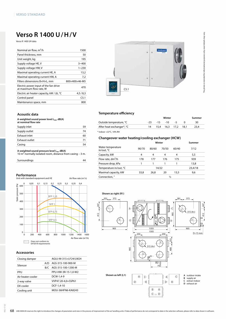
68
VERSO StandaRd
281252 372372
905905 13551505
905
905
247
247
412
412
С
B d
a
315 (4×)
315 (4×)
250
100
253
400
C
B
d
a
a
Bd
C
250
C
dB
a C
C
a
a
B
B
d
d
1500
50
195
3~400
1~230
13,2
7,2
800×400×46-M5
470
4,5 / 8,3
C5.1
800
14 15,4 16,3 17,2 18,1 23,459
74
60
71
54
44
4 4 4 4 5,5
178 177 176 175 939
1 1 1 1 13,8
14/22 23,4/18
33,8 26,8 20 13,5 9,6
½
Verso R 1400 U / H / V
aGUJ-M-315+LF24/LM24
aGS-315-100-900-M
aGS-315-100-1200-M
PPU-HW-3R-15-1,0-W2
dCW-1,4-9
VVP47.20-4,0+SSP61
dCF-1,4-10
MOU-36HFN6-Ka8243
600
500
400
300
200
100
00 200 400 600 800 1000 1200 1400 1600
0 0,05 0,1 0,15 0,2 0,25 0,3 0,35 0,4
SFP 1,25
SFP 0,5
SFP 1
SFP 0,75
C5.1
d=15 mm
750
The
phot
o is
inte
nded
for i
nfor
mat
iona
l pur
pose
s on
ly, e
xact
det
ails
may
var
y.
Acoustic dataA-weighted sound power level LwA, dB(A)at nominal flow rate
Supply inlet
Supply outlet
Exhaust inlet
Exhaust outlet
Casing
A-weighted sound pressure level LPA, dB(A) 10 m² normally isolated room, distance from casing – 3 m.
Surroundings
Nominal air flow, m³/h
Panel thickness, mm
Unit weight, kg
Supply voltage HE, V
Supply voltage HW, V
Maximal operating current HE, A
Maximal operating current HW, A
Filters dimensions B×H×L, mm
Electric power input of the fan drive at maximum flow rate, W
Electric air heater capacity, kW / ∆t, °C
Control panel
Maintenance space, mm
Temperature efficiencywinter Summer
Outside temperature, °C -23 -15 -10 -5 0 30
After heat exchanger*, °C
* indoor +22°C, 10% RH
Changeover water heating/cooling exchanger (HCw)winter Summer
Water temperature in/out, °C 90/70 80/60 70/50 60/40 7/12
Capacity, kW
Flow rate, dm³/h
Pressure drop, kPa
Temperature in/out, °C
Maximal capacity, kW
Connection, ”
Stat
ic p
ress
ure
(Pa)
air flow rate (m3/s)
air flow rate (m3/h)
PerformanceUnit with standard equipment and HE
KK2-
17-0
2
UAB AMALVA reserves the right to introduce the changes of parameters and sizes in the process of improvement of the air handling units. If data of performance do not correspond to data in the selection software, please refer to data shown in software.
Accessories
Closing damper
SilencerA/D
B/C
PPU
Air heater-cooler
2-way valve
DX cooler
Cooling unit
A outdoor intakeB supply airC extract indoorD exhaust air
Shown as left (L1)
Shown as right (R1)
Verso R 1400 UH data
does not conform to ErP2018 requirements
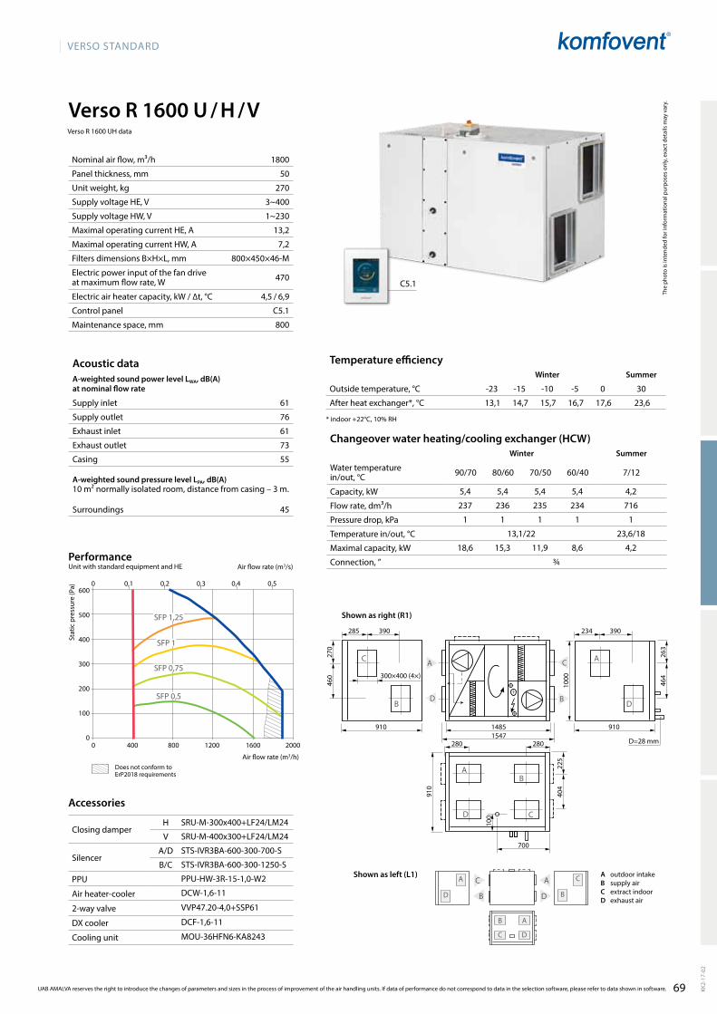
69
VERSO StandaRd
1800
50
270
3~400
1~230
13,2
7,2
800×450×46-M
470
4,5 / 6,9
C5.1
800
5,4 5,4 5,4 5,4 4,2
237 236 235 234 716
1 1 1 1 1
13,1/22 23,6/18
18,6 15,3 11,9 8,6 4,2
¾
C
dB
a
Verso R 1600 U / H / V
13,1 14,7 15,7 16,7 17,6 23,661
76
61
73
55
45
C
a C
d B
d
aB
300×400 (4×)
234285 390390
910910 14851547
1000
910
270
263
460
464
700
280280
100
225
404
a
Bd
CС a
B d
C
B
d
a
SRU-M-300x400+LF24/LM24
SRU-M-400x300+LF24/LM24
STS-IVR3BA-600-300-700-S
STS-IVR3BA-600-300-1250-S
PPU-HW-3R-15-1,0-W2
dCW-1,6-11
VVP47.20-4,0+SSP61
dCF-1,6-11
MOU-36HFN6-Ka8243
600
500
400
300
200
100
00 400 800 1200 1600 2000
0 0,1 0,2 0,3 0,4 0,5
SFP 1,25
SFP 0,5
SFP 1
SFP 0,75
C5.1
d=28 mm
UAB AMALVA reserves the right to introduce the changes of parameters and sizes in the process of improvement of the air handling units. If data of performance do not correspond to data in the selection software, please refer to data shown in software. KK2-
17-0
2
The
phot
o is
inte
nded
for i
nfor
mat
iona
l pur
pose
s on
ly, e
xact
det
ails
may
var
y.
Acoustic dataA-weighted sound power level LwA, dB(A)at nominal flow rate
Supply inlet
Supply outlet
Exhaust inlet
Exhaust outlet
Casing
A-weighted sound pressure level LPA, dB(A) 10 m² normally isolated room, distance from casing – 3 m.
Surroundings
Nominal air flow, m³/h
Panel thickness, mm
Unit weight, kg
Supply voltage HE, V
Supply voltage HW, V
Maximal operating current HE, A
Maximal operating current HW, A
Filters dimensions B×H×L, mm
Electric power input of the fan drive at maximum flow rate, W
Electric air heater capacity, kW / ∆t, °C
Control panel
Maintenance space, mm
Temperature efficiencyWinter Summer
Outside temperature, °C -23 -15 -10 -5 0 30
After heat exchanger*, °C
* indoor +22°C, 10% RH
Changeover water heating/cooling exchanger (HCW)Winter Summer
Water temperature in/out, °C 90/70 80/60 70/50 60/40 7/12
Capacity, kW
Flow rate, dm³/h
Pressure drop, kPa
Temperature in/out, °C
Maximal capacity, kW
Connection, ”
Stat
ic p
ress
ure
(Pa)
air flow rate (m3/s)
air flow rate (m3/h)
PerformanceUnit with standard equipment and HE
Accessories
Closing damperH
V
SilencerA/D
B/C
PPU
Air heater-cooler
2-way valve
DX cooler
Cooling unit
A outdoor intakeB supply airC extract indoorD exhaust air
Shown as left (L1)
Shown as right (R1)
Verso R 1600 UH data
does not conform to ErP2018 requirements
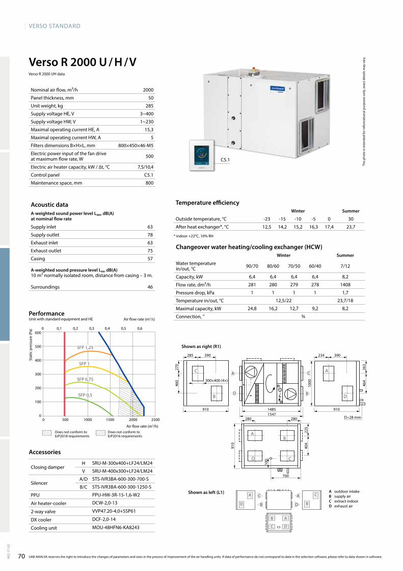
70
VERSO StandaRd
C
dB
a
C
a C
d B
d
aB
Verso R 2000 U / H / V
2000
50
285
3~400
1~230
15,3
5
800×450×46-M5
500
7,5/10,4
C5.1
800
12,5 14,2 15,2 16,3 17,4 23,763
78
63
75
57
46
6,4 6,4 6,4 6,4 8,2
281 280 279 278 1408
1 1 1 1 1,7
12,5/22 23,7/18
24,8 16,2 12,7 9,2 8,2
¾
300×400 (4×)
234285 390390
910910 14851547
1000
910
270
263
460
464
700
280280
100
225
404
a
Bd
CС a
B d
C
B
d
a
SRU-M-300x400+LF24/LM24
SRU-M-400x300+LF24/LM24
STS-IVR3BA-600-300-700-S
STS-IVR3BA-600-300-1250-S
PPU-HW-3R-15-1,6-W2
dCW-2,0-13
VVP47.20-4,0+SSP61
dCF-2,0-14
MOU-48HFN6-Ka8243
600
500
400
300
200
100
00 500 1000 1500 2000 2500
0 0,1 0,2 0,3 0,4 0,5 0,6
SFP 1,25
SFP 0,5
SFP 1
SFP 0,75
C5.1
d=28 mm
UAB AMALVA reserves the right to introduce the changes of parameters and sizes in the process of improvement of the air handling units. If data of performance do not correspond to data in the selection software, please refer to data shown in software.KK2-
17-0
2
The
phot
o is
inte
nded
for i
nfor
mat
iona
l pur
pose
s on
ly, e
xact
det
ails
may
var
y.
Acoustic dataA-weighted sound power level LwA, dB(A)at nominal flow rate
Supply inlet
Supply outlet
Exhaust inlet
Exhaust outlet
Casing
A-weighted sound pressure level LPA, dB(A) 10 m² normally isolated room, distance from casing – 3 m.
Surroundings
Nominal air flow, m³/h
Panel thickness, mm
Unit weight, kg
Supply voltage HE, V
Supply voltage HW, V
Maximal operating current HE, A
Maximal operating current HW, A
Filters dimensions B×H×L, mm
Electric power input of the fan drive at maximum flow rate, W
Electric air heater capacity, kW / ∆t, °C
Control panel
Maintenance space, mm
Temperature efficiencywinter Summer
Outside temperature, °C -23 -15 -10 -5 0 30
After heat exchanger*, °C
* indoor +22°C, 10% RH
Changeover water heating/cooling exchanger (HCw)winter Summer
Water temperature in/out, °C 90/70 80/60 70/50 60/40 7/12
Capacity, kW
Flow rate, dm³/h
Pressure drop, kPa
Temperature in/out, °C
Maximal capacity, kW
Connection, ”
Stat
ic p
ress
ure
(Pa)
air flow rate (m3/s)
air flow rate (m3/h)
PerformanceUnit with standard equipment and HE
Accessories
Closing damperH
V
SilencerA/D
B/C
PPU
Air heater-cooler
2-way valve
DX cooler
Cooling unit
A outdoor intakeB supply airC extract indoorD exhaust air
Shown as left (L1)
Shown as right (R1)
Verso R 2000 UH data
does not conform to ErP2018 requirements
does not conform to ErP2016 requirements

71
VERSO StandaRd
Verso R 2000 F
2000
50
280
3~400
1~230
17,1
6,8
560×420×96-M5
660
7,5/10,4
C5.1
400
14,2 15,6 16,5 17,3 18,2 23,4
69
79
69
79
59
49
107
60013
17
1210
305
305
355 (4×)
C
B a
d
264
220572 264
600
5262060
d
a B
C
B
B
d
d
a
a
C
C
5,2 5,2 5,2 5,2
231 230 229 228
6 6,1 6,3 6,4
14,2/22
18,6 15,2 11,7 8,4
½
600×510×310
dH355
aGUJ-M-355+LF24/LM24
aGS-355-100-900-M
aGS-355-100-1200-M
PPU-HW-3R-15-1,6-W2
dCW-2,0-13
VVP47.20-4,0+SSP61
dCF-2,0-14
MOU-48HFN6-Ka8243
600
500
400
300
200
100
00 400 800 1200 1600 2000 2400
0 0,1 0,2 0,3 0,4 0,5 0,6
SFP 0,5
SFP 0,75
SFP 1
SFP 1,25
C5.1
The
phot
o is
inte
nded
for i
nfor
mat
iona
l pur
pose
s on
ly, e
xact
det
ails
may
var
y.
Hot water duct air heater (DH)**Winter
Water temperature in/out, °C 90/70 80/60 70/50 60/40
Capacity, kW
Flow rate, dm³/h
Pressure drop, kPa
Temperature in/out, °C
Maximal capacity, kW
Connection, ”
Dimensions, mm
Hot water duct heater type
** option
Temperature efficiencyWinter Summer
Outside temperature, °C -23 -15 -10 -5 0 30
After heat exchanger*, °C
* indoor +22°C, 10% RH
Acoustic dataA-weighted sound power level LwA, dB(A)at nominal flow rate
Supply inlet
Supply outlet
Exhaust inlet
Exhaust outlet
Casing
A-weighted sound pressure level LPA, dB(A) 10 m² normally isolated room, distance from casing – 3 m.
Surroundings
Nominal air flow, m³/h
Panel thickness, mm
Unit weight, kg
Supply voltage HE, V
Supply voltage HW, V
Maximal operating current HE, A
Maximal operating current HW, A
Filters dimensions B×H×L, mm
Electric power input of the fan drive at maximum flow rate, W
Electric air heater capacity, kW / ∆t, °C
Control panel
Maintenance space, mm
Stat
ic p
ress
ure
(Pa)
air flow rate (m3/s)
air flow rate (m3/h)
PerformanceUnit with standard equipment and HE
KK2-
17-0
2
UAB AMALVA reserves the right to introduce the changes of parameters and sizes in the process of improvement of the air handling units. If data of performance do not correspond to data in the selection software, please refer to data shown in software.
Accessories
Closing damper
SilencerA/D
B/C
PPU
Air heater-cooler
2-way valve
DX cooler
Cooling unit
A outdoor intakeB supply airC extract indoorD exhaust air
Shown as right (R1)
Shown as left (L1)
does not conform to ErP2018 requirements
does not conform to ErP2016 requirements
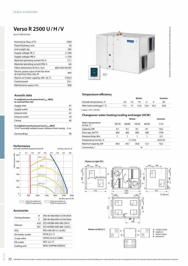
72
VERSO StandaRd
Verso R 2500 U / H / V
2500
50
285
3~400
1~230
17,1
6,8
800×450×46-M5
660
7,5/8,3
C5.1
800
9,1 9,1 9,1 9,1 10,2
404 402 400 398 1749
1 1 1 1 2,5
11,1/22 23,9/18
38,4 29,7 20,8 12,1 10,2
¾
11,1 13 14,2 15,4 16,7 23,967
82
67
79
60
49
C
dB
a
C
a C
d B
d
aB
300×400 (4×)
234285 390390
910910 14851547
1000
910
270
263
460
464
280280
100
225
404
a
Bd
CС a
B d
C
B
d
a
SRU-M-300x400+LF24/LM24
SRU-M-400x300+LF24/LM24
STS-IVR3BA-600-400-700-S
STS-IVR3BA-600-400-1250-S
PPU-HW-3R-15-1,6-W2
dCW-2,5-17
VVP45.25-6,3+SSB61
dCF-2,5-17
MOU-55HFN6-Ka8243
600
500
400
300
200
100
00 500 1000 1500 2000 2500 3000
0 0,1 0,2 0,3 0,4 0,5 0,6 0,7 0,8
SFP 1,25
SFP 0,5
SFP 1
SFP 0,75
C5.1
d=28 mm
700
UAB AMALVA reserves the right to introduce the changes of parameters and sizes in the process of improvement of the air handling units. If data of performance do not correspond to data in the selection software, please refer to data shown in software.KK2-
17-0
2
The
phot
o is
inte
nded
for i
nfor
mat
iona
l pur
pose
s on
ly, e
xact
det
ails
may
var
y.
Acoustic dataA-weighted sound power level LwA, dB(A)at nominal flow rate
Supply inlet
Supply outlet
Exhaust inlet
Exhaust outlet
Casing
A-weighted sound pressure level LPA, dB(A) 10 m² normally isolated room, distance from casing – 3 m.
Surroundings
Nominal air flow, m³/h
Panel thickness, mm
Unit weight, kg
Supply voltage HE, V
Supply voltage HW, V
Maximal operating current HE, A
Maximal operating current HW, A
Filters dimensions B×H×L, mm
Electric power input of the fan drive at maximum flow rate, W
Electric air heater capacity, kW / ∆t, °C
Control panel
Maintenance space, mm
Temperature efficiencywinter Summer
Outside temperature, °C -23 -15 -10 -5 0 30
After heat exchanger*, °C
* indoor +22°C, 10% RH
Changeover water heating/cooling exchanger (HCw)winter Summer
Water temperature in/out, °C 90/70 80/60 70/50 60/40 7/12
Capacity, kW
Flow rate, dm³/h
Pressure drop, kPa
Temperature in/out, °C
Maximal capacity, kW
Connection, ”
Stat
ic p
ress
ure
(Pa)
air flow rate (m3/s)
air flow rate (m3/h)
PerformanceUnit with standard equipment and HE
Accessories
Closing damperH
V
SilencerA/D
B/C
PPU
Air heater-cooler
2-way valve
DX cooler
Cooling unit
Shown as left (L1)
Shown as right (R1)
A outdoor intakeB supply airC extract indoorD exhaust air
Verso R 2500 UH data
does not conform to ErP2018 requirements
does not conform to ErP2016 requirements

73
VERSO StandaRd
Verso R 3000 U / H / V
3600
50
440 (135/160/145)
3~400
3~400
16,7
4,2
525×510×46-M5 (×2)
1000
9/6,9
C5.1
1000
12,4 14,1 15,2 16,3 17,3 23,766
83
67
80
57
46
11,6 11,6 11,6 11,6 13,1
512 509 507 505 2252
1 1 1 1 3,8
12,4/22 23,7/18
58,1 45,8 33,7 21,5 16,1
1
1150
1150
323
d
a
323 323
323 323
400 400
500
500
59730
3
303
C
B
a
d C
B
650 700 750328,5
504
1150 1150
C
B a
d
B
d
a
C
C
a
d
B
SRU-M-400x500+LF24/LM24
SRU-M-500x400+LF24/LM24
STS-IVR3BA-600-500-700-S
STS-IVR3BA-600-500-1250-S
PPU-HW-3R-15-2,5-W2
dCW-3,0-20
VVP45.25-6,3+SSB61
dCF-3,0-20-2
2xMOU-36HFN6-Ka8243
600
500
400
300
200
100
0
0 0,15 0,3 0,45 0,6 0,75 0,9 1,05
SFP 1,25
SFP 0,5
SFP 1
SFP 0,75
0 500 1000 1500 2000 2500 3000 3500 4000
C5.1
d=28 mm
UAB AMALVA reserves the right to introduce the changes of parameters and sizes in the process of improvement of the air handling units. If data of performance do not correspond to data in the selection software, please refer to data shown in software. KK2-
17-0
2
The
phot
o is
inte
nded
for i
nfor
mat
iona
l pur
pose
s on
ly, e
xact
det
ails
may
var
y.
Acoustic dataA-weighted sound power level LwA, dB(A)at nominal flow rate
Supply inlet
Supply outlet
Exhaust inlet
Exhaust outlet
Casing
A-weighted sound pressure level LPA, dB(A) 10 m² normally isolated room, distance from casing – 3 m.
Surroundings
Nominal air flow, m³/h
Panel thickness, mm
Unit weight, kg
Supply voltage HE, V
Supply voltage HW, V
Maximal operating current HE, A
Maximal operating current HW, A
Filters dimensions B×H×L, mm
Electric power input of the fan drive at maximum flow rate, W
Electric air heater capacity, kW / ∆t, °C
Control panel
Maintenance space, mm
Temperature efficiencyWinter Summer
Outside temperature, °C -23 -15 -10 -5 0 30
After heat exchanger*, °C
* indoor +22°C, 10% RH
Changeover water heating/cooling exchanger (HCW)Winter Summer
Water temperature in/out, °C 90/70 80/60 70/50 60/40 7/12
Capacity, kW
Flow rate, dm³/h
Pressure drop, kPa
Temperature in/out, °C
Maximal capacity, kW
Connection, ”
Stat
ic p
ress
ure
(Pa)
air flow rate (m3/s)
air flow rate (m3/h)
PerformanceUnit with standard equipment and HE
Accessories
Closing damperH
V
SilencerA/D
B/C
PPU
Air heater-cooler
2-way valve
DX cooler
Cooling unit
A outdoor intakeB supply airC extract indoorD exhaust air
Shown as right (R1)
Shown as left (L1)
Verso R 3000 UH data
does not conform to ErP2018 requirements
does not conform to ErP2016 requirements
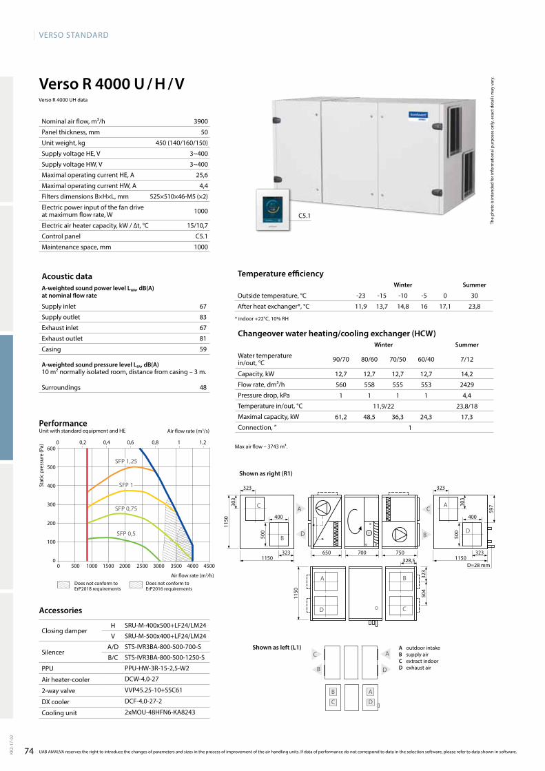
74
VERSO StandaRd
3900
50
450 (140/160/150)
3~400
3~400
25,6
4,4
525×510×46-M5 (×2)
1000
15/10,7
C5.1
1000
11,9 13,7 14,8 16 17,1 23,867
83
67
81
59
48
12,7 12,7 12,7 12,7 14,2
560 558 555 553 2429
1 1 1 1 4,4
11,9/22 23,8/18
61,2 48,5 36,3 24,3 17,3
1
Verso R 4000 U / H / V
1150
1150
323
d
a
323 323
323 323
400 400
500
500
59730
3
303
C
B
a
d C
B
650 700 750328,5
504
1150 1150
C
B a
d
B
d
a
C
C
a
d
B
SRU-M-400x500+LF24/LM24
SRU-M-500x400+LF24/LM24
STS-IVR3BA-800-500-700-S
STS-IVR3BA-800-500-1250-S
PPU-HW-3R-15-2,5-W2
dCW-4,0-27
VVP45.25-10+SSC61
dCF-4,0-27-2
2xMOU-48HFN6-Ka8243
600
500
400
300
200
100
00 500 1000 1500 2000 2500 3000 3500 4000 4500
SFP 1,25
SFP 0,5
SFP 1
SFP 0,75
0 0,2 0,4 0,6 0,8 1 1,2
C5.1
d=28 mm
UAB AMALVA reserves the right to introduce the changes of parameters and sizes in the process of improvement of the air handling units. If data of performance do not correspond to data in the selection software, please refer to data shown in software.KK2-
17-0
2
The
phot
o is
inte
nded
for i
nfor
mat
iona
l pur
pose
s on
ly, e
xact
det
ails
may
var
y.
Acoustic dataA-weighted sound power level LwA, dB(A)at nominal flow rate
Supply inlet
Supply outlet
Exhaust inlet
Exhaust outlet
Casing
A-weighted sound pressure level LPA, dB(A) 10 m² normally isolated room, distance from casing – 3 m.
Surroundings
Nominal air flow, m³/h
Panel thickness, mm
Unit weight, kg
Supply voltage HE, V
Supply voltage HW, V
Maximal operating current HE, A
Maximal operating current HW, A
Filters dimensions B×H×L, mm
Electric power input of the fan drive at maximum flow rate, W
Electric air heater capacity, kW / ∆t, °C
Control panel
Maintenance space, mm
Temperature efficiencywinter Summer
Outside temperature, °C -23 -15 -10 -5 0 30
After heat exchanger*, °C
* indoor +22°C, 10% RH
Changeover water heating/cooling exchanger (HCw)winter Summer
Water temperature in/out, °C 90/70 80/60 70/50 60/40 7/12
Capacity, kW
Flow rate, dm³/h
Pressure drop, kPa
Temperature in/out, °C
Maximal capacity, kW
Connection, ”
Stat
ic p
ress
ure
(Pa)
air flow rate (m3/s)
air flow rate (m3/h)
PerformanceUnit with standard equipment and HE
Accessories
Closing damperH
V
SilencerA/D
B/C
PPU
Air heater-cooler
2-way valve
DX cooler
Cooling unit
A outdoor intakeB supply airC extract indoorD exhaust air
Shown as right (R1)
Shown as left (L1)
Max air flow – 3743 m³.
Verso R 4000 UH data
does not conform to ErP2018 requirements
does not conform to ErP2016 requirements
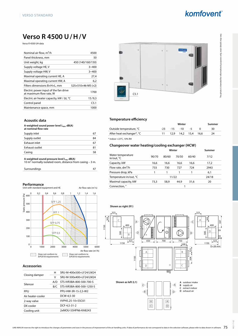
75
VERSO StandaRd
Verso R 4500 U / H / V
4500
50
450 (140/160/150)
3~400
3~400
27,4
6,2
525×510×46-M5 (×2)
1700
15 / 9,3
C5.1
1000
11 12,9 14,2 15,4 16,6 2467
84
67
81
58
47
16,6 16,6 16,6 16,6 17,2
733 730 727 724 2943
1 1 1 1 6,1
11/22 24/18
73,3 58,9 44,9 31,6 20
1
1150
1150
323
d
a
323 323
323 323
400 400
500
500
59730
3
303
C
B
a
d C
B
650 700 750328,5
504
1150 1150
C
B a
d
B
d
a
C
C
a
d
B
SRU-M-400x500+LF24/LM24
SRU-M-500x400+LF24/LM24
STS-IVR3BA-800-500-700-S
STS-IVR3BA-800-500-1250-S
PPU-HW-3R-15-2,5-W2
dCW-4,5-30
VVP45.25-10+SSC61
dCF-4,5-31-2
2xMOU-55HFN6-Ka8243
600
500
400
300
200
100
00 1000 2000 3000 4000 5000 6000
SFP 1,25
SFP 0,5
SFP 1
SFP 0,75
0 0,2 0,4 0,6 0,8 1 1,2 1,4 1,6
C5.1
d=28 mm
UAB AMALVA reserves the right to introduce the changes of parameters and sizes in the process of improvement of the air handling units. If data of performance do not correspond to data in the selection software, please refer to data shown in software. KK2-
17-0
2
The
phot
o is
inte
nded
for i
nfor
mat
iona
l pur
pose
s on
ly, e
xact
det
ails
may
var
y.
Acoustic dataA-weighted sound power level LwA, dB(A)at nominal flow rate
Supply inlet
Supply outlet
Exhaust inlet
Exhaust outlet
Casing
A-weighted sound pressure level LPA, dB(A) 10 m² normally isolated room, distance from casing – 3 m.
Surroundings
Nominal air flow, m³/h
Panel thickness, mm
Unit weight, kg
Supply voltage HE, V
Supply voltage HW, V
Maximal operating current HE, A
Maximal operating current HW, A
Filters dimensions B×H×L, mm
Electric power input of the fan drive at maximum flow rate, W
Electric air heater capacity, kW / ∆t, °C
Control panel
Maintenance space, mm
Temperature efficiencyWinter Summer
Outside temperature, °C -23 -15 -10 -5 0 30
After heat exchanger*, °C
* indoor +22°C, 10% RH
Changeover water heating/cooling exchanger (HCW)Winter Summer
Water temperature in/out, °C 90/70 80/60 70/50 60/40 7/12
Capacity, kW
Flow rate, dm³/h
Pressure drop, kPa
Temperature in/out, °C
Maximal capacity, kW
Connection, ”
Stat
ic p
ress
ure
(Pa)
air flow rate (m3/s)
air flow rate (m3/h)
PerformanceUnit with standard equipment and HE
Accessories
Closing damperH
V
SilencerA/D
B/C
PPU
Air heater-cooler
2-way valve
DX cooler
Cooling unit
A outdoor intakeB supply airC extract indoorD exhaust air
Shown as right (R1)
Shown as left (L1)
Verso R 4500 UH data
does not conform to ErP2018 requirements
does not conform to ErP2016 requirements

76
VERSO StandaRd
Verso R 7000 H
8000
50
780 (270/230/280)
3~400
12,8
592×592-8×635-M5(×2)
2730
C5.1
1400
11,6 13,4 14,6 15,8 16,9 23,8
70
89
72
88
64
53
27,9 27,9 27,9 27,9
1232 1226 1221 1216
5,9 6,1 6,2 6,4
11,6/22
83 66,4 58,1 41
1
C
B
B a
C d
1200
750
600
1520
600
125 390 750 1500
d
a
С
B
SRU-M-1200x600+LF24/LM24
STS-IVR3BA-1200-600-700-S
STS-IVR3BA-1200-600-1250-S
PPU-HW-3R-20-4,0-W2
dCW-7,0-47
HRB33216+AMB162
dCF-7,0-48-3
3xMOU-55HFN6-Ka8243
C5.1
d
a
d=28 mm
600
500
400
300
200
100
00 1000 2000 3000 4000 5000 6000 7000 8000 9000
SFP 1,25
SFP 0,5
SFP 1
SFP 0,75
0 0,4 0,8 1,2 1,6 2 2,4
The
phot
o is
inte
nded
for i
nfor
mat
iona
l pur
pose
s on
ly, e
xact
det
ails
may
var
y.
Hot water air heaterWinter
Water temperature in/out, °C 90/70 80/60 70/50 60/40
Capacity, kW
Flow rate, dm³/h
Pressure drop, kPa
Temperature in/out, °C
Maximal capacity, kW
Connection, ”
Temperature efficiencyWinter Summer
Outside temperature, °C -23 -15 -10 -5 0 30
After heat exchanger*, °C
* indoor +22°C, 10% RH
Acoustic dataA-weighted sound power level LWA, dB(A)at nominal flow rate
Supply inlet
Supply outlet
Exhaust inlet
Exhaust outlet
Casing
A-weighted sound pressure level LPA, dB(A) 10 m² normally isolated room, distance from casing – 3 m.
Surroundings
Nominal air flow, m³/h
Panel thickness, mm
Unit weight, kg
Supply voltage, V
Maximal operating current, A
Filters dimensions B×H×L, mm
Electric power input of the fan drive at maximum flow rate, W
Control panel
Maintenance space, mm
Stat
ic p
ress
ure
(Pa)
air flow rate (m3/s)
air flow rate (m3/h)
PerformanceUnit with standard equipment
KK2-
17-0
2
UAB AMALVA reserves the right to introduce the changes of parameters and sizes in the process of improvement of the air handling units. If data of performance do not correspond to data in the selection software, please refer to data shown in software.
Accessories
Closing damper
SilencerA/D
B/C
PPU
Air heater-cooler
2-way valve
DX cooler
Cooling unit
A outdoor intakeB supply airC extract indoorD exhaust air
Shown as right (R1)
Shown as left (L1)
does not conform to ErP2018 requirements
does not conform to ErP2016 requirements
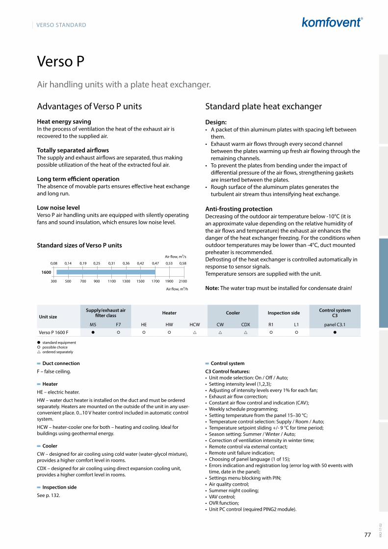
77
VERSO StandaRd
Verso P
300 500 700 900 1100 1300 1500 1700 1900 2100
0,08 0,14 0,19 0,25 0,31 0,36 0,42 0,47 0,53 0,58
1600
KK2-
17-0
2
advantages of Verso P units
Heat energy savingIn the process of ventilation the heat of the exhaust air is recovered to the supplied air.
Totally separated airflowsthe supply and exhaust airflows are separated, thus making possible utilization of the heat of the extracted foul air.
Long term efficient operationthe absence of movable parts ensures effective heat exchange and long run.
Low noise levelVerso P air handling units are equipped with silently ope rating fans and sound insulation, which ensures low noise level.
Standard plate heat exchanger
Design:• a packet of thin aluminum plates with spacing left bet ween
them.• Exhaust warm air flows through every second channel
between the plates warming up fresh air flowing through the remaining channels.
• to prevent the plates from bending under the impact of differential pressure of the air flows, strengthening gaskets are inserted between the plates.
• Rough surface of the aluminum plates generates the turbulent air stream thus intensifying heat exchange.
Anti-frosting protectiondecreasing of the outdoor air temperature below -10°C (it is an approximate value depending on the relative humidity of the air flows and temperature) the exhaust air enhances the danger of the heat exchanger freezing. For the conditions when outdoor temperatures may be lower than -4°C, duct mounted preheater is recommended.defrosting of the heat exchanger is controlled automa tically in response to sensor signals. temperature sensors are supplied with the unit.
Note: the water trap must be installed for condensate drain!
air handling units with a plate heat exchanger.
air flow, m³/s
air flow, m³/h
Standard sizes of Verso P units
Duct connection
F – false ceiling.
Heater
HE – electric heater.
HW – water duct heater is installed on the duct and must be ordered separately. Heaters are mounted on the outside of the unit in any user-convenient place. 0...10 V heater control included in automatic control system.
HCW – heater-cooler one for both – heating and cooling. Ideal for buildings using geothermal energy.
Cooler
CW – designed for air cooling using cold water (water-glycol mixture), provides a higher comfort level in rooms.
CdX – designed for air cooling using direct expansion cooling unit, provides a higher comfort level in rooms.
Inspection side
See p. 132.
Control system
C3 Control features:• Unitmodeselection:On/Off/Auto;• Settingintensitylevel(1,2,3);• Adjustingofintensitylevelsevery1%foreachfan;• Exhaustairflowcorrection;• Constantairflowcontrolandindication(CAV);• Weeklyscheduleprogramming;• Settingtemperaturefromthepanel15–30°C;• Temperaturecontrolselection:Supply/Room/Auto;• Temperaturesetpointsliding+/-9°Cfortimeperiod;• Seasonsetting:Summer/Winter/Auto;• Correctionofventilationintensityinwintertime;• Remotecontrolviaexternalcontact;• Remoteunitfailureindication;• Choosingofpanellanguage(1of15);• Errorsindicationandregistrationlog(errorlogwith50eventswithtime,dateinthepanel);
• SettingsmenublockingwithPIN;• Airqualitycontrol;• Summernightcooling;• VAVcontrol;• OVRfunction;• UnitPCcontrol(requiredPING2module).
� standard equipment� possible choice ordered separately
Unit sizeSupply/exhaust air
filter class Heater Cooler Inspection side Control systemC3
M5 F7 HE HW HCW CW CdX R1 L1 panel C3.1
Verso P 1600 F � � � � � � �
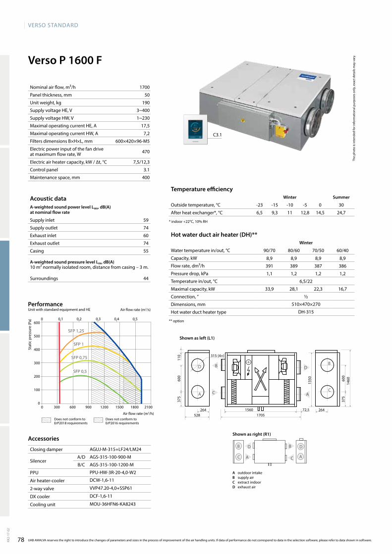
78
VERSO StandaRd
Verso P 1600 F
1700
50
190
3~400
1~230
17,5
7,2
600×420×96-M5
470
7,5/12,3
3.1
400
6,5 9,3 11 12,8 14,5 24,7
59
74
60
74
55
44
8,9 8,9 8,9 8,9
391 389 387 386
1,1 1,2 1,2 1,2
6,5/22
33,9 28,1 22,3 16,7
½
510×470×270
dH-315
a
dB
C C
C
d
d
a
a
B
B
110
600
600
1350
1460
375
375
315 (4×)
a
dB
C
264528
15601705
72,5 264
aGUJ-M-315+LF24/LM24
aGS-315-100-900-M
aGS-315-100-1200-M
PPU-HW-3R-20-4,0-W2
dCW-1,6-11
VVP47.20-4,0+SSP61
dCF-1,6-11
MOU-36HFN6-Ka8243
600
500
400
300
200
100
00 300 600 900 1200 1500 1800 2100
0 0,1 0,2 0,3 0,4 0,5
SFP 1,25
SFP 0,5
SFP 1
SFP 0,75
C3.1
The
phot
o is
inte
nded
for i
nfor
mat
iona
l pur
pose
s on
ly, e
xact
det
ails
may
var
y.
Hot water duct air heater (DH)**Winter
Water temperature in/out, °C 90/70 80/60 70/50 60/40
Capacity, kW
Flow rate, dm³/h
Pressure drop, kPa
Temperature in/out, °C
Maximal capacity, kW
Connection, ”
Dimensions, mm
Hot water duct heater type
** option
Temperature efficiencyWinter Summer
Outside temperature, °C -23 -15 -10 -5 0 30
After heat exchanger*, °C
* indoor +22°C, 10% RH
Acoustic dataA-weighted sound power level LWA, dB(A)at nominal flow rate
Supply inlet
Supply outlet
Exhaust inlet
Exhaust outlet
Casing
A-weighted sound pressure level LPA, dB(A) 10 m² normally isolated room, distance from casing – 3 m.
Surroundings
Nominal air flow, m³/h
Panel thickness, mm
Unit weight, kg
Supply voltage HE, V
Supply voltage HW, V
Maximal operating current HE, A
Maximal operating current HW, A
Filters dimensions B×H×L, mm
Electric power input of the fan drive at maximum flow rate, W
Electric air heater capacity, kW / ∆t, °C
Control panel
Maintenance space, mm
Stat
ic p
ress
ure
(Pa)
air flow rate (m3/s)
air flow rate (m3/h)
PerformanceUnit with standard equipment and HE
KK2-
17-0
2
UAB AMALVA reserves the right to introduce the changes of parameters and sizes in the process of improvement of the air handling units. If data of performance do not correspond to data in the selection software, please refer to data shown in software.
Accessories
Closing damper
SilencerA/D
B/C
PPU
Air heater-cooler
2-way valve
DX cooler
Cooling unit
Shown as right (R1)
A outdoor intakeB supply airC extract indoorD exhaust air
Shown as left (L1)
does not conform to ErP2018 requirements
does not conform to ErP2016 requirements
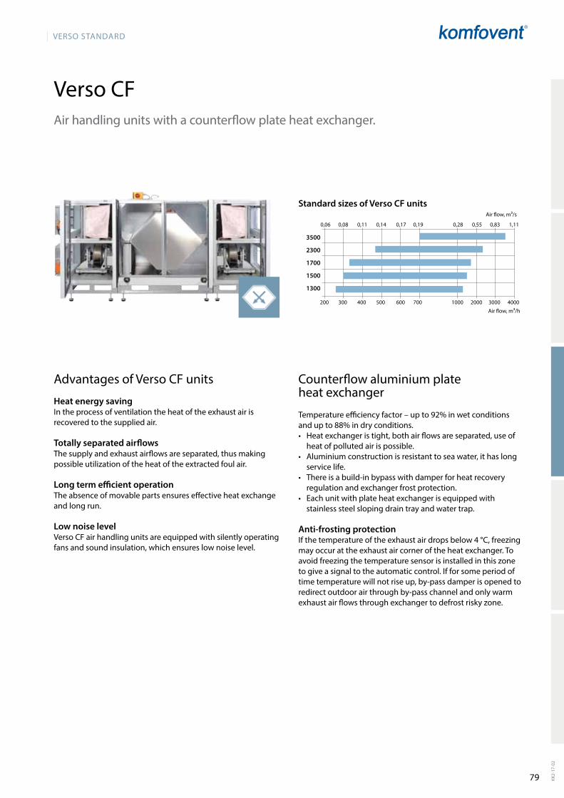
79
VERSO StandaRd
Verso CF
200 300 400 500 600 700 1000 2000 3000 4000
0,06 0,08 0,11 0,14 0,17 0,19 0,28 0,55 0,83 1,11
3500
2300
1700
1500
1300
KK2-
17-0
2
air handling units with a counterflow plate heat exchanger.
advantages of Verso CF units
Heat energy savingIn the process of ventilation the heat of the exhaust air is recovered to the supplied air.
Totally separated airflowsthe supply and exhaust airflows are separated, thus making possible utilization of the heat of the extracted foul air.
Long term efficient operationthe absence of movable parts ensures effective heat exchange and long run.
Low noise levelVerso CF air handling units are equipped with silently operating fans and sound insulation, which ensures low noise level.
Counterflow aluminium plate heat exchanger
Temperatureefficiencyfactor–upto92%inwetconditionsandupto88%indryconditions.• Heat exchanger is tight, both air flows are separated, use of
heat of polluted air is possible.• aluminium construction is resistant to sea water, it has long
service life.• there is a build-in bypass with damper for heat recovery
regulation and exchanger frost protection.• Each unit with plate heat exchanger is equipped with
stainless steel sloping drain tray and water trap.
Anti-frosting protectionIf the temperature of the exhaust air drops below 4 °C, freezing may occur at the exhaust air corner of the heat exchanger. to avoid free zing the temperature sensor is installed in this zone to give a signal to the automatic control. If for some period of time temperature will not rise up, by-pass damper is opened to redirect outdoor air through by-pass channel and only warm exhaust air flows through exchanger to defrost risky zone.
Standard sizes of Verso CF units
air flow, m³/h
air flow, m³/s

80
VERSO StandaRd
UAB AMALVA reserves the right to introduce the changes of parameters and sizes in the process of improvement of the air handling units.KK2-
17-0
2
Duct connection
H – horizontal.V – vertical.U – universal, 14 installation options.F – false ceiling.
Heater
HE – electric heater.
HW – water duct heater is installed on the duct and must be ordered separately. Heaters are mounted on the outside of the unit in any user-convenient place. 0...10 V heater control included in automatic control system.
HCW – heater-cooler one for both – heating and cooling. Ideal for buildings using geothermal energy.
Cooler
CW – designed for air cooling using cold water (water-glycol mixture), provides a higher comfort level in rooms.
CdX – designed for air cooling using direct expansion cooling unit, provides a higher comfort level in rooms.
Inspection side
See p. 132
Control system
C5 Control features:• 5differentoperationmodes:Comfort1, Comfort2, Economy1,
Economy2 and Special;• Temperaturecontrolmodes:Supplyair/Extractair/Room;• Energyparametersindication:thermalefficiencyoftheheat
exchanger, heat exchanger's recovered energy, energy saving indicator;
• Airquality,minimumtemperaturecontrol;• Flowcontrolmodes:CAV,VAVandDCV;• Weeklyoperatingschedule;• Airflowindication(m3/h, m3/s,l/s);• Rotaryorplateheatexchangerfailureprotection;• Rotaryheatexchangercleaningandwarm-upfunction;• Intelligentself-diagnostic;• Summernightcooling;• Airqualityfunction;• Supplyairtemperaturecontrol;• Min.supplyairtemperaturemaintenance;• Combinedwaterheater&coolercontrol;• Inverter-typeDXoutdoorunitcontrol;• Coolingrecoveryfunction;• Outdoorcompensatedventilation;• Humiditycontrol:airhumidificationanddehumidification*;• Circulationpumpscontrolbydemand;• Warm-upfunctionofcirculationpumpsandmixingvalves;• Airfiltercloggingindication;• Operationhoursandenergycounters;• Remotecontrolviawebinterface;• Built-indataloggerforallairhandlingunitparameters;• Applicationsoftwareforsmartphonesbasedon“Android”and“iOS”.
* additionallyorderedfunction.
Verso CF range
� standard equipment� possible choice ordered separately
Unit sizeSupply / exhaust air
filter class Heater Cooler Inspection side Control system C5
M5 F7 HE HW HCW CW CdX R1 L1 panel C5.1
Verso CF 1300 U � � � � � � �
Verso CF 1300 F � � � � � �
Verso CF 1500 F � � � � � �
Verso CF 1700 U � � � � � � �
Verso CF 2300 U � � � � � � �
Verso CF 3500 U � � � � � �

81
VERSO StandaRd
Verso CF 1300 U/H/V
13 14,5 15,5 16,5 17,5 23,762
80
62
80
58
47
1300
50
269
3~400
1~230
10,8
4,8
800×400×46-M5
273
4,5 / 9,6
C5.1
800
3,9 3,9 3,9 3,9 5
173 173 172 171 849
1 1 1 1 11,1
13/22 23,7/18
27,7 22,1 16,7 11,4 8
½
242
1962
905
242
1810
C
d
a
B
253
980
905
430
253
108
253253
315 (4×)
a
d C
B
B
a C
d
a C
B
C
a
d
d B
259
910285 100
d=15 mm
d
a
aGUJ-M-315+LF24/LM24
aGS-315-100-900-M
aGS-315-100-1200-M
PPU-HW-3R-15-2,5-W2
dCW-1,4-9
VVP47.20-4,0+SSP61
dCF-1,4-10
MOU-36HFN6-Ka8243
0 200 400 600 800 1000 1200 1400 1600
600
500
400
300
200
100
0
0 0,05 0,1 0,15 0,2 0,25 0,3 0,35 0,4
SFP 0,75
SFP 1
SFP 1,25
SFP 0,5
C5.1
The
phot
o is
inte
nded
for i
nfor
mat
iona
l pur
pose
s on
ly, e
xact
det
ails
may
var
y.
Acoustic dataA-weighted sound power level LwA, dB(A)at nominal flow rate
Supply inlet
Supply outlet
Exhaust inlet
Exhaust outlet
Casing
A-weighted sound pressure level LPA, dB(A) 10 m² normally isolated room, distance from casing – 3 m.
Surroundings
Nominal air flow, m³/h
Panel thickness, mm
Unit weight, kg
Supply voltage HE, V
Supply voltage HW, V
Maximal operating current HE, A
Maximal operating current HW, A
Filters dimensions B×H×L, mm
Electric power input of the fan drive at maximum flow rate, W
Electric air heater capacity, kW / ∆t, °C
Control panel
Maintenance space, mm
Temperature efficiencyWinter Summer
Outside temperature, °C -23 -15 -10 -5 0 30
After heat exchanger*, °C
* indoor +22°C, 10% RH
Changeover water heating/cooling exchanger (HCW)Winter Summer
Water temperature in/out, °C 90/70 80/60 70/50 60/40 7/12
Capacity, kW
Flow rate, dm³/h
Pressure drop, kPa
Temperature in/out, °C
Maximal capacity, kW
Connection, ”
Stat
ic p
ress
ure
(Pa)
air flow rate (m3/s)
air flow rate (m3/h)
PerformanceUnit with standard equipment and HE
KK2-
17-0
2
UAB AMALVA reserves the right to introduce the changes of parameters and sizes in the process of improvement of the air handling units. If data of performance do not correspond to data in the selection software, please refer to data shown in software.
Accessories
Closing damper
SilencerA/D
B/C
PPU
Air heater-cooler
2-way valve
DX cooler
Cooling unit
available versions:1)Electricairheater(HE);2)Changeoverwaterheating/coolingexchanger(HCW);3) Changeover water heating/cooling exchanger (HCW) and electric air heater (HE).
Shown as right (R1)
Shown as left (L1) A outdoor intakeB supply airC extract indoorD exhaust air
does not conform to ErP2018 requirements

82
VERSO StandaRd
Verso CF 1300 F
13 14,5 15,5 16,5 17,5 23,7
64
80
64
80
58
47
1300
50
162
3~400
1~230
10,8
4,8
550×420×46-M5
273
4,5 / 9,6
C5.1
400
16501795
263
550
275
B d
aC C
d
a
B
C
B d
a a
B
C
d
1100
110
d=15 mm
315 (4×)
3,9 3,9 3,9 3,9
174 173 172 172
3,2 3,2 3,3 3,4
13/22
13,1 10,7 8,3 6
½
510×470×270
dH-315
527
aGUJ-M-315+LF24/LM24
aGS-315-100-900-M
aGS-315-100-1200-M
PPU-HW-3R-15-2,5-W2
dCW-1,4-9
VVP47.20-4,0+SSP61
dCF-1,4-10
MOU-36HFN6-Ka8243
0 200 400 600 800 1000 1200 1400 1600
600
500
400
300
200
100
0
0 0,05 0,1 0,15 0,2 0,25 0,3 0,35 0,4
SFP 1,25
SFP 1
SFP 0,75
SFP 0,5
C5.1
The
phot
o is
inte
nded
for i
nfor
mat
iona
l pur
pose
s on
ly, e
xact
det
ails
may
var
y.
Hot water duct air heater (DH)**Winter
Water temperature in/out, °C 90/70 80/60 70/50 60/40
Capacity, kW
Flow rate, dm³/h
Pressure drop, kPa
Temperature in/out, °C
Maximal capacity, kW
Connection, ”
Dimensions, mm
Hot water duct heater type
** option
Temperature efficiencyWinter Summer
Outside temperature, °C -23 -15 -10 -5 0 30
After heat exchanger*, °C
* indoor +22°C, 10% RH
Acoustic dataA-weighted sound power level LWA, dB(A)at nominal flow rate
Supply inlet
Supply outlet
Exhaust inlet
Exhaust outlet
Casing
A-weighted sound pressure level LPA, dB(A) 10 m² normally isolated room, distance from casing – 3 m.
Surroundings
Nominal air flow, m³/h
Panel thickness, mm
Unit weight, kg
Supply voltage HE, V
Supply voltage HW, V
Maximal operating current HE, A
Maximal operating current HW, A
Filters dimensions B×H×L, mm
Electric power input of the fan drive at maximum flow rate, W
Electric air heater capacity, kW / ∆t, °C
Control panel
Maintenance space, mm
Stat
ic p
ress
ure
(Pa)
air flow rate (m3/s)
air flow rate (m3/h)
PerformanceUnit with standard equipment and HE
KK2-
17-0
2
UAB AMALVA reserves the right to introduce the changes of parameters and sizes in the process of improvement of the air handling units. If data of performance do not correspond to data in the selection software, please refer to data shown in software.
Accessories
Closing damper
SilencerA/D
B/C
PPU
Air heater-cooler
2-way valve
DX cooler
Cooling unit
Shown as left (L1)
A outdoor intakeB supply airC extract indoorD exhaust air
Shown as right (R1)
does not conform to ErP2018 requirements
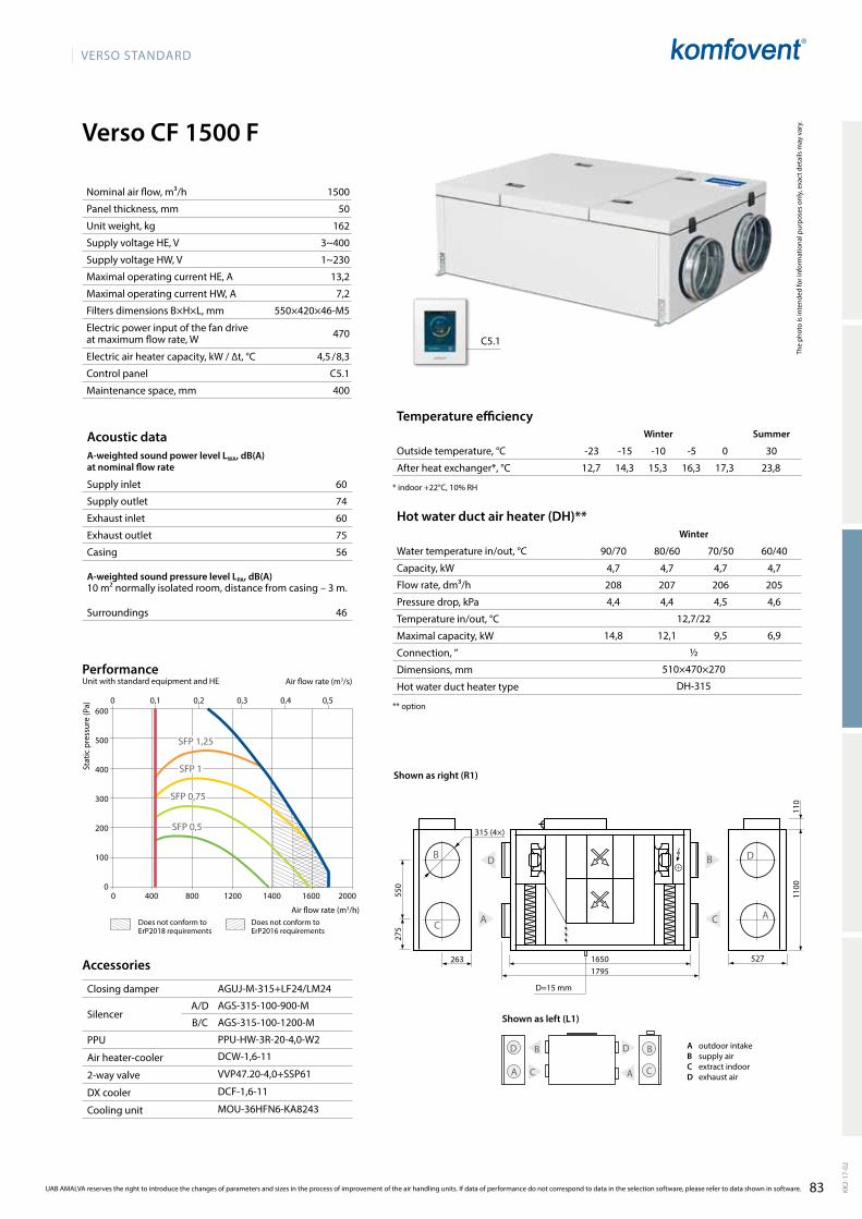
83
VERSO StandaRd
Verso CF 1500 F
12,7 14,3 15,3 16,3 17,3 23,8
60
74
60
75
56
46
1500
50
162
3~400
1~230
13,2
7,2
550×420×46-M5
470
4,5 / 8,3
C5.1
400
16501795
263
550
275
B d
aC C
d
a
B
C
B d
a a
B
C
d
1100
110
d=15 mm
315 (4×)
4,7 4,7 4,7 4,7
208 207 206 205
4,4 4,4 4,5 4,6
12,7/22
14,8 12,1 9,5 6,9
½
510×470×270
dH-315
527
aGUJ-M-315+LF24/LM24
aGS-315-100-900-M
aGS-315-100-1200-M
PPU-HW-3R-20-4,0-W2
dCW-1,6-11
VVP47.20-4,0+SSP61
dCF-1,6-11
MOU-36HFN6-Ka8243
0 400 800 1200 1400 1600 2000
600
500
400
300
200
100
0
0 0,1 0,2 0,3 0,4 0,5
SFP 1,25
SFP 0,75
SFP 0,5
SFP 1
C5.1
The
phot
o is
inte
nded
for i
nfor
mat
iona
l pur
pose
s on
ly, e
xact
det
ails
may
var
y.
Hot water duct air heater (DH)**Winter
Water temperature in/out, °C 90/70 80/60 70/50 60/40
Capacity, kW
Flow rate, dm³/h
Pressure drop, kPa
Temperature in/out, °C
Maximal capacity, kW
Connection, ”
Dimensions, mm
Hot water duct heater type
** option
Temperature efficiencyWinter Summer
Outside temperature, °C -23 -15 -10 -5 0 30
After heat exchanger*, °C
* indoor +22°C, 10% RH
Acoustic dataA-weighted sound power level LwA, dB(A)at nominal flow rate
Supply inlet
Supply outlet
Exhaust inlet
Exhaust outlet
Casing
A-weighted sound pressure level LPA, dB(A) 10 m² normally isolated room, distance from casing – 3 m.
Surroundings
Nominal air flow, m³/h
Panel thickness, mm
Unit weight, kg
Supply voltage HE, V
Supply voltage HW, V
Maximal operating current HE, A
Maximal operating current HW, A
Filters dimensions B×H×L, mm
Electric power input of the fan drive at maximum flow rate, W
Electric air heater capacity, kW / ∆t, °C
Control panel
Maintenance space, mm
Stat
ic p
ress
ure
(Pa)
air flow rate (m3/s)
air flow rate (m3/h)
PerformanceUnit with standard equipment and HE
KK2-
17-0
2
UAB AMALVA reserves the right to introduce the changes of parameters and sizes in the process of improvement of the air handling units. If data of performance do not correspond to data in the selection software, please refer to data shown in software.
Accessories
Closing damper
SilencerA/D
B/C
PPU
Air heater-cooler
2-way valve
DX cooler
Cooling unit
Shown as left (L1)
A outdoor intakeB supply airC extract indoorD exhaust air
Shown as right (R1)
does not conform to ErP2018 requirements
does not conform to ErP2016 requirements
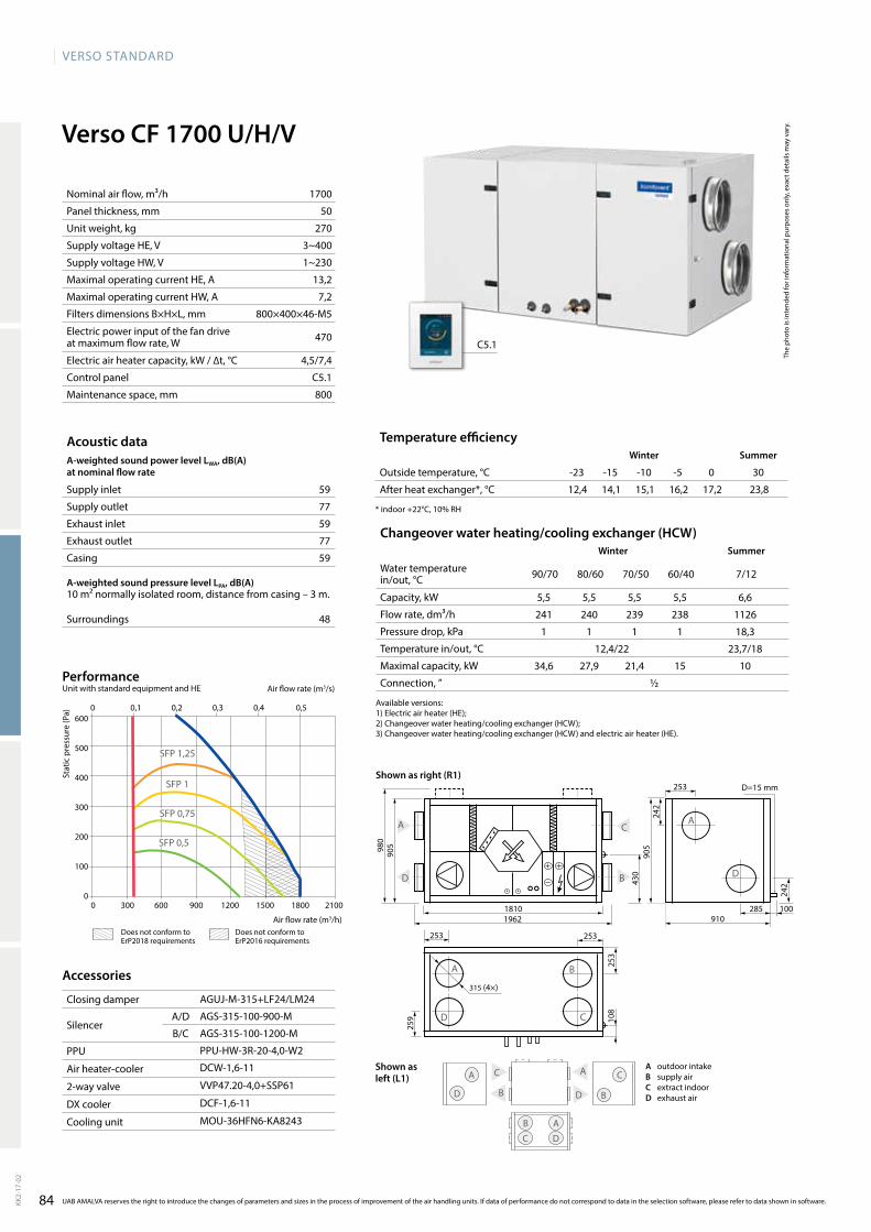
84
VERSO StandaRd
Verso CF 1700 U/H/V
12,4 14,1 15,1 16,2 17,2 23,859
77
59
77
59
48
1700
50
270
3~400
1~230
13,2
7,2
800×400×46-M5
470
4,5/7,4
C5.1
800
5,5 5,5 5,5 5,5 6,6
241 240 239 238 1126
1 1 1 1 18,3
12,4/22 23,7/18
34,6 27,9 21,4 15 10
½
242
1962
905
242
1810
C
d
a
B
253
980
905
430
253
108
253253
315 (4×)
a
d C
B
B
a C
d
a C
B
C
a
d
d B
259
910285 100
d=15 mm
d
a
aGUJ-M-315+LF24/LM24
aGS-315-100-900-M
aGS-315-100-1200-M
PPU-HW-3R-20-4,0-W2
dCW-1,6-11
VVP47.20-4,0+SSP61
dCF-1,6-11
MOU-36HFN6-Ka8243
C5.1
0 0,1 0,2 0,3 0,4 0,5
0 300 600 900 1200 1500 1800 2100
600
500
400
300
200
100
0
SFP 1,25
SFP 1
SFP 0,75
SFP 0,5
The
phot
o is
inte
nded
for i
nfor
mat
iona
l pur
pose
s on
ly, e
xact
det
ails
may
var
y.
Acoustic dataA-weighted sound power level LwA, dB(A)at nominal flow rate
Supply inlet
Supply outlet
Exhaust inlet
Exhaust outlet
Casing
A-weighted sound pressure level LPA, dB(A) 10 m² normally isolated room, distance from casing – 3 m.
Surroundings
Nominal air flow, m³/h
Panel thickness, mm
Unit weight, kg
Supply voltage HE, V
Supply voltage HW, V
Maximal operating current HE, A
Maximal operating current HW, A
Filters dimensions B×H×L, mm
Electric power input of the fan drive at maximum flow rate, W
Electric air heater capacity, kW / ∆t, °C
Control panel
Maintenance space, mm
Temperature efficiencywinter Summer
Outside temperature, °C -23 -15 -10 -5 0 30
After heat exchanger*, °C
* indoor +22°C, 10% RH
Changeover water heating/cooling exchanger (HCw)winter Summer
Water temperature in/out, °C 90/70 80/60 70/50 60/40 7/12
Capacity, kW
Flow rate, dm³/h
Pressure drop, kPa
Temperature in/out, °C
Maximal capacity, kW
Connection, ”
Stat
ic p
ress
ure
(Pa)
air flow rate (m3/s)
air flow rate (m3/h)
PerformanceUnit with standard equipment and HE
KK2-
17-0
2
UAB AMALVA reserves the right to introduce the changes of parameters and sizes in the process of improvement of the air handling units. If data of performance do not correspond to data in the selection software, please refer to data shown in software.
Accessories
Closing damper
SilencerA/D
B/C
PPU
Air heater-cooler
2-way valve
DX cooler
Cooling unit
available versions:1)Electricairheater(HE);2)Changeoverwaterheating/coolingexchanger(HCW);3) Changeover water heating/cooling exchanger (HCW) and electric air heater (HE).
Shown as right (R1)
Shown as left (L1)
A outdoor intakeB supply airC extract indoorD exhaust air
does not conform to ErP2018 requirements
does not conform to ErP2016 requirements

85
VERSO StandaRd
14,4 15,5 16,2 17 17,8 23,563
81
63
81
61
50
2300
50
250
3~400
1~230
17,1
6,8
800×400×46-M5
660
7,5 / 9,1
C5.1
800
5,9 5,9 5,9 5,9 8,5
259 258 257 256 1459
1 1 1 1,1 29
14,4/22 23,5/18
42,6 33,9 25,6 17,6 12,4
½
Verso CF 2300 U/H/V
d
a
935
905
20602000
281
300
100
256
250
a
d C
B
910261 100
d=28 mm
250
250
C
B
410
250
d
a
C
dB
a
C
a C
d B
d
aB
400
300
SRU-M-300x400+LF24/LM24
SRU-M-400x300+LF24/LM24
STS-IVR3BA-600-400-700-S
STS-IVR3BA-600-400-1250-S
PPU-HW-3R-20-4,0-W2
dCW-2,5-17
VVP45.25-6,3+SSB61
dCF-2,5-17
MOU-55HFN6-Ka8243
C5.1
0 500 1000 1500 2000 2500 3000
600
500
400
300
200
100
0
0 0,1 0,2 0,3 0,4 0,5 0,6 0,7 0,8
SFP 1,25
SFP 0,75
SFP 0,5
SFP 1
UAB AMALVA reserves the right to introduce the changes of parameters and sizes in the process of improvement of the air handling units. If data of performance do not correspond to data in the selection software, please refer to data shown in software. KK2-
17-0
2
The
phot
o is
inte
nded
for i
nfor
mat
iona
l pur
pose
s on
ly, e
xact
det
ails
may
var
y.
Acoustic dataA-weighted sound power level LwA, dB(A)at nominal flow rate
Supply inlet
Supply outlet
Exhaust inlet
Exhaust outlet
Casing
A-weighted sound pressure level LPA, dB(A) 10 m² normally isolated room, distance from casing – 3 m.
Surroundings
Nominal air flow, m³/h
Panel thickness, mm
Unit weight, kg
Supply voltage HE, V
Supply voltage HW, V
Maximal operating current HE, A
Maximal operating current HW, A
Filters dimensions B×H×L, mm
Electric power input of the fan drive at maximum flow rate, W
Electric air heater capacity, kW / ∆t, °C
Control panel
Maintenance space, mm
Temperature efficiencyWinter Summer
Outside temperature, °C -23 -15 -10 -5 0 30
After heat exchanger*, °C
* indoor +22°C, 10% RH
Changeover water heating/cooling exchanger (HCW)Winter Summer
Water temperature in/out, °C 90/70 80/60 70/50 60/40 7/12
Capacity, kW
Flow rate, dm³/h
Pressure drop, kPa
Temperature in/out, °C
Maximal capacity, kW
Connection, ”
Stat
ic p
ress
ure
(Pa)
air flow rate (m3/s)
air flow rate (m3/h)
PerformanceUnit with standard equipment and HE
Accessories
Closing damperH
V
SilencerA/D
B/C
PPU
Air heater-cooler
2-way valve
DX cooler
Cooling unit
available versions:1)Electricairheater(HE);2)Changeoverwaterheating/coolingexchanger(HCW);3) Changeover water heating/cooling exchanger (HCW) and electric air heater (HE).
Shown as right (R1)
Shown as left (L1)
A outdoor intakeB supply airC extract indoorD exhaust air
does not conform to ErP2018 requirements
does not conform to ErP2016 requirements
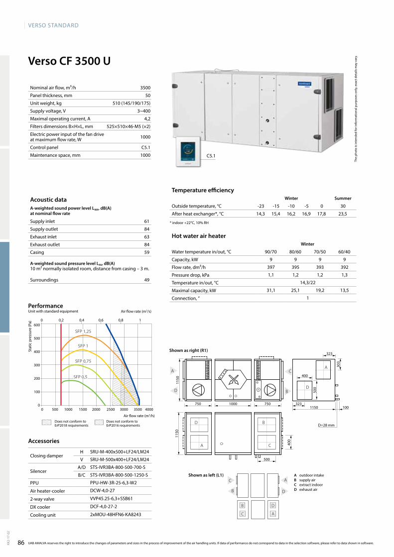
86
VERSO StandaRd
14,3 15,4 16,2 16,9 17,8 23,5
61
84
63
84
59
49
3500
50
510 (145/190/175)
3~400
4,2
525×510×46-M5 (×2)
1000
C5.1
1000
Verso CF 3500 U
d=28 mm
d
a
d
a
B
C
d
C a
B
C
B d
a
B
a C
d
1150
303
500
323
400
323100
400
500
1150
750 1000 7501150
9 9 9 9
397 395 393 392
1,1 1,2 1,2 1,3
14,3/22
31,1 25,1 19,2 13,5
1
SRU-M-400x500+LF24/LM24
SRU-M-500x400+LF24/LM24
STS-IVR3BA-800-500-700-S
STS-IVR3BA-800-500-1250-S
PPU-HW-3R-25-6,3-W2
dCW-4,0-27
VVP45.25-6,3+SSB61
dCF-4,0-27-2
2xMOU-48HFN6-Ka8243
C5.1
0 0,2 0,4 0,6 0,8 1
0 500 1000 1500 2000 2500 3000 3500 4000
600
500
400
300
200
100
0
SFP 1,25
SFP 1
SFP 0,75
SFP 0,5
The
phot
o is
inte
nded
for i
nfor
mat
iona
l pur
pose
s on
ly, e
xact
det
ails
may
var
y.
Hot water air heaterWinter
Water temperature in/out, °C 90/70 80/60 70/50 60/40
Capacity, kW
Flow rate, dm³/h
Pressure drop, kPa
Temperature in/out, °C
Maximal capacity, kW
Connection, ”
Temperature efficiencyWinter Summer
Outside temperature, °C -23 -15 -10 -5 0 30
After heat exchanger*, °C
* indoor +22°C, 10% RH
Acoustic dataA-weighted sound power level LWA, dB(A)at nominal flow rate
Supply inlet
Supply outlet
Exhaust inlet
Exhaust outlet
Casing
A-weighted sound pressure level LPA, dB(A) 10 m² normally isolated room, distance from casing – 3 m.
Surroundings
Nominal air flow, m³/h
Panel thickness, mm
Unit weight, kg
Supply voltage, V
Maximal operating current, A
Filters dimensions B×H×L, mm
Electric power input of the fan drive at maximum flow rate, W
Control panel
Maintenance space, mm
Stat
ic p
ress
ure
(Pa)
air flow rate (m3/s)
air flow rate (m3/h)
PerformanceUnit with standard equipment
KK2-
17-0
2
UAB AMALVA reserves the right to introduce the changes of parameters and sizes in the process of improvement of the air handling units. If data of performance do not correspond to data in the selection software, please refer to data shown in software.
Accessories
Closing damperH
V
SilencerA/D
B/C
PPU
Air heater-cooler
2-way valve
DX cooler
Cooling unit
Shown as right (R1)
Shown as left (L1) A outdoor intakeB supply airC extract indoorD exhaust air
does not conform to ErP2018 requirements
does not conform to ErP2016 requirements

87
VERSO StandaRd
Verso S
200 300 400 500 600 700 800 1000 2000 3000 4000
0,06 0,08 0,11 0,14 0,17 0,19 0,22 0,28 0,55 0,83 1,11
4000
3000
2100
1300
KK2-
17-0
2
Duct connectionF – false ceiling.
Heater
HE – electric heater.
HW – water air heater.
HCW – heater-cooler one for both – heating and cooling.
advantages of Verso S units
• Height is only 297 mm / 350 mm / 545 mm – easy to choose the place for installation.
• Units are complemented with fastening profiles and vib-ration absorbing holders.
• Safe and handy design of removable cover ensures easy fi xing of cover at different opening levels for perfor ming maintenance and service inspection.
• air handling units have integrated control system.• Control panel may be installed in any user-convenient place.• Control panel display enables to set the operation para-
meters of the unit and monitor them.• there is a possibility to complement and control the duct
mounted cooling section.
False ceiling supply air handling units.
Verso S range
Cooler
CW – designed for air cooling using cold water (water-glycol mixture), provides a higher comfort level in rooms.
CdX – designed for air cooling using direct expansion cooling unit, provides a higher comfort level in rooms.
Inspection side
See p. 132
Control system
More information about C5 on p. 10.
� standard equipment� possible choice ordered separately
Unit sizeSupply/exhaust
air filter class Heater Cooler Inspection side Control system C5
M5 F7 HE HW HCW CW CdX R1 panel C5.1
Verso S 1300 F � � � � � �
Verso S 2100 F � � � � � �
Verso S 3000 F � � � � �
Verso S 4000 F � � � � �
Standard sizes of Verso S units
air flow, m³/h
air flow, m³/s

88
VERSO StandaRd
72
78
54
44
1200
50
46
558×287×46-M5
273
C5.1
400
90/70 80/60 70/50 60/40
17,3 16,6 14,1 8,6
764 731 617 374
2 1,9 1,5 1
-23/20 -23/18,4 -23/12,1 -10/11,3
18,9 16,6 14,1 8,6
½
Verso S 1300 F-HE/9 3~400 9,0 15,4 21
Verso S 1300 F-HE/15 3~400 15,0 24,1 35
Verso S 1300 F-HW 1~230 – 2,9 –
Verso S 1300 F
893
700×
350
d=250
aGUJ-M-250+LF24/LM24
aGS-250-50-600-M
aGS-250-50-900-M
PPU-HW-3R-25-6,3-W2
dCW-1,4-9
VVP47.20-4,0+SSP61
dCF-1,4-10
MOU-36HFN6-Ka8243
C5.1
0 0,05 0,1 0,15 0,2 0,25 0,3 0,35 0,4
0 300 600 900 1200 1500
600
500
400
300
200
100
0
SFP 1,25
SFP 1
SFP 0,75
SFP 0,5
Acoustic dataA-weighted sound power level LwA, dB(A)at nominal flow rate
Supply inlet
Supply outlet
Casing
A-weighted sound pressure level LPA, dB(A) 10 m² normally isolated room, distance from casing – 3 m.
Surroundings
Nominal air flow, m³/h
Panel thickness, mm
Unit weight, kg
Filters dimensions B×H×L, mm
Electric power input of the fan drive at reference flow rate, W
Control panel
Maintenance space, mm
Hot water air heaterWater temperature in/out, °C
Capacity, kW
Flow rate, dm³/h
Pressure drop, kPa
Temperature in/out, °C
Maximal capacity, kW
Connection, ”
The
phot
o is
inte
nded
for i
nfor
mat
iona
l pur
pose
s on
ly, e
xact
det
ails
may
var
y.
Technical data
Supply air handling unit
Supply voltage, V
Air heater capacity, kw
Maximal operating current, A
ΔT, °C
Stat
ic p
ress
ure
(Pa)
Air flow rate (m3/s)
Air flow rate (m3/h)
PerformanceUnit with standard equipment and HE
Accessories
Closing damper
SilencerA/D
B/C
PPU
Air heater-cooler
2-way valve
DX cooler
Cooling unit
UAB AMALVA reserves the right to introduce the changes of parameters and sizes in the process of improvement of the air handling units. If data of performance do not correspond to data in the selection software, please refer to data shown in software.KK2-
17-0
2
does not conform to ErP2018 requirements
does not conform to ErP2016 requirements

VERSO StandaRd
89
Verso S 2100 F
893
1000
×350
700×250
70
75
52
42
2000
50
73
858×287×46-M5
2×170
C5.1
400
90/70 80/60 70/50 60/40
28,8 28,8 25,5 16,5
1273 1257 1115 718
7,6 7,8 6,4 3
-23/20 -23/20 -23/15 -10/14,5
33,3 29,5 25,5 16,5
½
Verso S 2100 F-HE/15 3~400 15,0 25,0 21
Verso S 2100 F-HE/22,5 3~400 22,5 35,9 31
Verso S 2100 F-HW 1~230 – 3,8 –
SRU-M-700x250+LF24/LM24
STS-IVR3BA-800-250-700-S
STS-IVR3BA-800-250-1250-S
PPU-HW-3R-25-10-W3
dCW-2,0-13
VVP47.20-4,0+SSP61
dCF-2,0-14
MOU-48HFN6-Ka8243
C5.1
0 300 600 900 1200 1500 1800 2100 2400
500
400
300
200
100
0
0 0,1 0,2 0,3 0,4 0,5 0,6
SFP 1,25
SFP 0,75
SFP 0,5
SFP 1
Acoustic dataA-weighted sound power level LwA, dB(A)at nominal flow rate
Supply inlet
Supply outlet
Casing
A-weighted sound pressure level LPA, dB(A) 10 m² normally isolated room, distance from casing – 3 m.
Surroundings
Nominal air flow, m³/h
Panel thickness, mm
Unit weight, kg
Filters dimensions B×H×L, mm
Electric power input of the fan drive at reference flow rate, W
Control panel
Maintenance space, mm
Hot water air heaterWater temperature in/out, °C
Capacity, kW
Flow rate, dm³/h
Pressure drop, kPa
Temperature in/out, °C
Maximal capacity, kW
Connection, ”
The
phot
o is
inte
nded
for i
nfor
mat
iona
l pur
pose
s on
ly, e
xact
det
ails
may
var
y.
Technical data
Supply air handling unit
Supply voltage, V
Air heater capacity, kW
Maximal operating current, A
ΔT, °C
Stat
ic p
ress
ure
(Pa)
Air flow rate (m3/s)
Air flow rate (m3/h)
PerformanceUnit with standard equipment and HE
Accessories
Closing damper
SilencerA/D
B/C
PPU
Air heater-cooler
2-way valve
DX cooler
Cooling unit
KK2-
17-0
2
UAB AMALVA reserves the right to introduce the changes of parameters and sizes in the process of improvement of the air handling units. If data of performance do not correspond to data in the selection software, please refer to data shown in software.
does not conform to ErP2018 requirements
does not conform to ErP2016 requirements
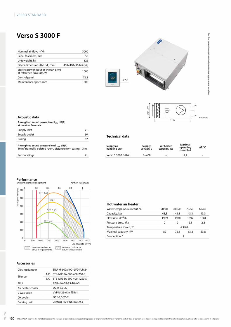
90
VERSO StandaRd
Verso S 3000 F
71
80
52
41
3000
50
125
450×480×96-M5 (×2)
1000
C5.1
500
Verso S 3000 F-HW 3~400 – 2,7 –
1160
1075
×555
600×400
SRU-M-600x400+LF24/LM24
STS-IVR3BA-600-400-700-S
STS-IVR3BA-600-400-1250-S
PPU-HW-3R-25-10-W3
dCW-3,0-20
VVP45.25-6,3+SSB61
dCF-3,0-20-2
2xMOU-36HFN6-Ka8243
C5.1
90/70 80/60 70/50 60/40
43,3 43,3 43,3 43,3
1909 1900 1892 1884
2 2 2,1 2,2
-23/20
82 72,6 63,2 53,8
10 500 1000 1500 2000 2500 3000 3500 4000
600
500
400
300
200
100
0
SFP 1,25
SFP 1
SFP 0,75
SFP 0,5
0 0,2 0,4 0,6 0,8 1
Acoustic dataA-weighted sound power level LwA, dB(A)at nominal flow rate
Supply inlet
Supply outlet
Casing
A-weighted sound pressure level LPA, dB(A) 10 m² normally isolated room, distance from casing – 3 m.
Surroundings
Nominal air flow, m³/h
Panel thickness, mm
Unit weight, kg
Filters dimensions B×H×L, mm
Electric power input of the fan drive at reference flow rate, W
Control panel
Maintenance space, mm
Hot water air heaterWater temperature in/out, °C
Capacity, kW
Flow rate, dm³/h
Pressure drop, kPa
Temperature in/out, °C
Maximal capacity, kW
Connection, ”
The
phot
o is
inte
nded
for i
nfor
mat
iona
l pur
pose
s on
ly, e
xact
det
ails
may
var
y.
Technical data
Supply air handling unit
Supply voltage, V
Air heater capacity, kw
Maximal operating current, A
ΔT, °C
Stat
ic p
ress
ure
(Pa)
Air flow rate (m3/s)
Air flow rate (m3/h)
Accessories
Closing damper
SilencerA/D
B/C
PPU
Air heater-cooler
2-way valve
DX cooler
Cooling unit
UAB AMALVA reserves the right to introduce the changes of parameters and sizes in the process of improvement of the air handling units. If data of performance do not correspond to data in the selection software, please refer to data shown in software.KK2-
17-0
2
PerformanceUnit with standard equipment
does not conform to ErP2018 requirements
does not conform to ErP2016 requirements

VERSO StandaRd
91
Verso S 4000 F
74
83
58
47
3700
50
125
450×480×96-M5 (×2)
1000
C5.1
500
Verso S 4000 F-HW 3~400 – 2,7 –
1160
1075
×555
600×400
SRU-M-600x400+LF24/LM24
STS-IVR3BA-800-400-700-S
STS-IVR3BA-800-400-1250-S
PPU-HW-3R-25-16-W3
dCW-4,0-27
VVP45.25-10+SSC61
dCF-4,0-27-2
2xMOU-48HFN6-Ka8243
90/70 80/60 70/50 60/40
55,8 55,8 55,8 55,8
2464 2453 2442 2432
3,1 3,2 3,3 3,4
-23/22
97,4 86,3 75,2 64,1
1
C5.1
0 500 1000 1500 2000 2500 3000 3500 4000
600
500
400
300
200
100
0
0 0,2 0,4 0,6 0,8 1
SFP 1,25
SFP 0,75
SFP 0,5
SFP 1
Acoustic dataA-weighted sound power level LwA, dB(A)at nominal flow rate
Supply inlet
Supply outlet
Casing
A-weighted sound pressure level LPA, dB(A) 10 m² normally isolated room, distance from casing – 3 m.
Surroundings
Nominal air flow, m³/h
Panel thickness, mm
Unit weight, kg
Filters dimensions B×H×L, mm
Electric power input of the fan drive at reference flow rate, W
Control panel
Maintenance space, mm
Hot water air heaterWater temperature in/out, °C
Capacity, kW
Flow rate, dm³/h
Pressure drop, kPa
Temperature in/out, °C
Maximal capacity, kW
Connection, ”
The
phot
o is
inte
nded
for i
nfor
mat
iona
l pur
pose
s on
ly, e
xact
det
ails
may
var
y.
Technical data
Supply air handling unit
Supply voltage, V
Air heater capacity, kW
Maximal operating current, A
ΔT, °C
Stat
ic p
ress
ure
(Pa)
Air flow rate (m3/s)
Air flow rate (m3/h)
Accessories
Closing damper
SilencerA/D
B/C
PPU
Air heater-cooler
2-way valve
DX cooler
Cooling unit
KK2-
17-0
2
UAB AMALVA reserves the right to introduce the changes of parameters and sizes in the process of improvement of the air handling units. If data of performance do not correspond to data in the selection software, please refer to data shown in software.
PerformanceUnit with standard equipment
does not conform to ErP2018 requirements
does not conform to ErP2016 requirements
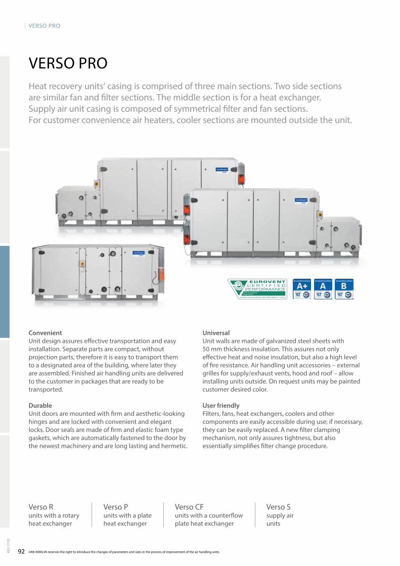
92
VERSO PRO
AHU N˚: 07.09.356Range: VERSO
UAB AMALVA reserves the right to introduce the changes of parameters and sizes in the process of improvement of the air handling units.KK2-
17-0
2
Heat recovery units‘ casing is comprised of three main sections. two side sections are similar fan and filter sections. the middle section is for a heat exchanger. Supply air unit casing is composed of symmetrical filter and fan sections. For customer convenience air heaters, cooler sections are mounted outside the unit.
ConvenientUnit design assures effective transportation and easy installation. Separate parts are compact, without projectionparts;thereforeitiseasytotransportthemto a designated area of the building, where later they are assembled. Fi nished air handling units are delivered to the customer in packages that are ready to be transported.
DurableUnit doors are mounted with firm and aesthetic-looking hinges and are locked with convenient and elegant locks. door seals are made of firm and elastic foam type gaskets, which are automatically fastened to the door by the newest machinery and are long lasting and hermetic.
Universal Unit walls are made of galvanized steel sheets with 50 mm thickness insulation. this assures not only effective heat and noise insulation, but also a high level of fire resistance. air handling unit accessories – external grilles for supply/exhaust vents, hood and roof – allow installing units outside. On request units may be painted customer desired color.
User friendlyFilters, fans, heat exchangers, coolers and other componentsareeasilyaccessibleduringuse;ifnecessary,they can be easily replaced. a new filter clamping mechanism, not only assures tightness, but also essentially simplifies filter change procedure.
VERSO PRO
Verso P units with a pla te he at ex chan ger
Verso R units with a ro ta ry he at ex chan ger
Verso CF units with a counterflow plate heat exchanger
Verso S sup ply air units

93
VERSO PRO
88%85%73%
All data can be calculated in VERSO selection software. If data of performance do not correspond to data in selection software, please refer to data shown in software. KK2-
17-0
2
design
Counter flow plate heat exchanger in dry conditions
Rotary heat exchanger
Plate heat exchanger in dry conditions
Counter flow plate heat exchanger
Used in Verso CF series units.Temperatureefficiencyfactor–upto92%inwetconditionsandupto88%indryconditions.the plate heat exchanger is equipped with automatic by-pass. aluminium plates are made of an aluminium alloy resistant to sea water.
Plate heat exchanger
Used in Verso P series units.Temperatureefficiencyfactor–upto75%inwetconditionsandupto73%indryconditions.aluminium plate-type heat exchangers are used in the units. aluminium plates are made of an aluminium alloy resistant to sea water.
Rotary heat exchanger
Used in Verso R series units. temperature efficiency factor – up to 85%.Possiblewaveheight:1,4mm;1,5mm,1,7mm.types of rotary heat exchangers:• Condensation(aluminium);• Hygroscopic(aluminiumandzeolith);• Sorption(aluminiumwithzeolithcoating);• Deepepoxycoating“Blygold”technology.aluminium foil is made of an aluminium alloy resistant to sea water. Rotary heat exchanger rotation speed is controlled by a frequency converter, according to the air temperature. the heat exchanger can be ordered with an installed purge section.
Increased efficiency for higher energy savings
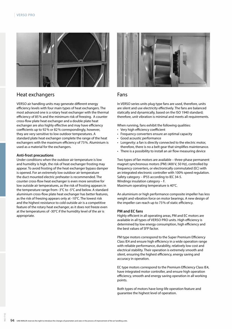
94
VERSO PRO
UAB AMALVA reserves the right to introduce the changes of parameters and sizes in the process of improvement of the air handling units.KK2-
17-0
2
Fans
In VERSO series units plug type fans are used, therefore, units are silent and use electricity effectively. the fans are balanced staticallyanddynamically,basedontheISO1940standard;therefore, unit vibration is minimal and meets all requirements.
When running, fans exhibit the following qualities:• Very high efficiency coefficient• Frequency converters ensure an optimal capacity• Good acoustic performance• Longevity: a fan is directly connected to the electric motor,
therefore, there is no a belt gear that simplifies maintenance.• there is a possibility to install an air flow measuring device
two types of fan motors are available – three-phase permanent magnet synchronous motors (PM) (400 V, 50 Hz), controlled by frequency converters, or electronically commutated (EC) with anintegratedelectroniccontrollerwith100%speedregulation.Safety category – IP55 according to IEC 34-5. Windings insulation category – F.Maximum operating temperature is 40°C.
an aluminium or high performance composite impeller has less weight and vibration force on motor bearings. a new design of theimpellercanreachupto73%ofstaticefficiency.
PM and EC fansHighly efficient in all operating areas, PM and EC motors are available in all types of VERSO PRO units. High efficiency is determined by low energy consumption, high efficiency and the best values of SFP factor.
PM type motors correspond to the Super Premium Efficiency Class IE4 and ensure high efficiency in a wide operation range with reliable performance, durability, relatively low cost and electrical stability. their operation is extremely smooth and silent, ensuring the highest efficiency, energy saving and accuracy in operation.
EC type motors correspond to the Premium Efficiency Class IE4, have integrated motor controller, and ensure high operation efficiency, smooth and energy saving operation in all working points.
Bothtypesofmotorshavelong-lifeoperationfeatureandguarantee the highest level of operation.
Heat exchangers
VERSO air handling units may generate different energy efficiency levels with four main types of heat exchangers. the most advanced one is a rotary heat exchanger with the thermal efficiencyof85%andtheminimumriskoffreezing.Acountercross-flow plate heat exchanger and a double plate heat exchanger are also highly effective and may have efficiency coefficientsupto92%or82%correspondingly,however,they are very sensitive to low outdoor temperatures. a standard plate heat exchanger complete the range of the heat exchangerswiththemaximumefficiencyof73%.Aluminiumisused as a material for the exchangers.
Anti-frost precautionsUnder conditions when the outdoor air temperature is low and humidity is high, the risk of heat exchanger frosting may appear. to avoid frosting of the heat exchanger bypass damper is opened. For an extremely low outdoor air temperature the duct mounted electric preheater is recommended. the counter cross-flow heat exchanger is even more sensitive for low outside air temperatures, as the risk of frosting appears in the temperature range from -3°C to -5°C and below. a stan dard aluminium cross-flow plate heat exchanger has better features, as the risk of freezing appears only at -10°C. the lo west risk and the highest resistance to cold outside air is a competitive feature of the rotary heat exchanger, as it does not freeze even at the temperatures of -30°C if the humi dity level of the air is appropriate.
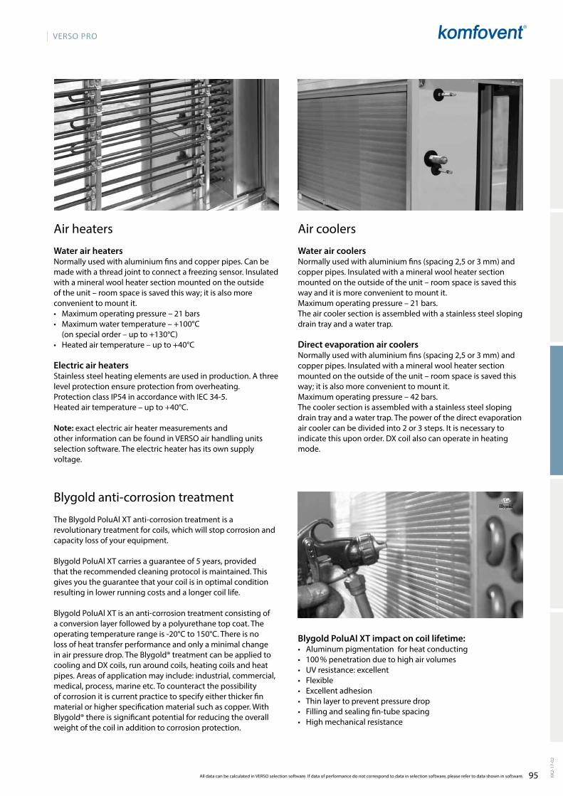
95
VERSO PRO
All data can be calculated in VERSO selection software. If data of performance do not correspond to data in selection software, please refer to data shown in software. KK2-
17-0
2
air coolers
Water air coolersNormally used with aluminium fins (spacing 2,5 or 3 mm) and copper pipes. Insulated with a mineral wool heater section mounted on the outside of the unit – room space is saved this way and it is more convenient to mount it. Maximum operating pressure – 21 bars.the air cooler section is assembled with a stainless steel sloping drain tray and a water trap.
Direct evaporation air coolersNormally used with aluminium fins (spacing 2,5 or 3 mm) and copper pipes. Insulated with a mineral wool heater section mounted on the outside of the unit – room space is saved this way;itisalsomoreconvenienttomountit.Maximum operating pressure – 42 bars.the cooler section is assembled with a stainless steel slo ping drain tray and a water trap. the power of the direct evaporation air cooler can be divided into 2 or 3 steps. It is necessary to indicate this upon order. dX coil also can operate in heating mode.
air heaters
Water air heatersNormally used with aluminium fins and copper pipes. Can be made with a thread joint to connect a freezing sensor. Insulated with a mineral wool heater section mounted on the outside oftheunit–roomspaceissavedthisway;itisalsomoreconvenient to mount it. • Maximum operating pressure – 21 bars• Maximum water temperature – +100°C
(on special order – up to +130°C)• Heated air temperature – up to +40°C
Electric air heatersStainless steel heating elements are used in production. a three level protection ensure protection from over heating.Protection class IP54 in accordance with IEC 34-5.Heated air temperature – up to +40°C.
Note: exact electric air heater measurements and other information can be found in VERSO air handling units selection software. the electric heater has its own supply voltage.
Blygoldanti-corrosiontreatment
TheBlygoldPoluAlXTanti-corrosiontreatmentisarevolutionary treatment for coils, which will stop corrosion and capacity loss of your equipment. BlygoldPoluAlXTcarriesaguaranteeof5years,providedthat the recommended cleaning protocol is maintained. this gives you the guarantee that your coil is in optimal condition resulting in lower running costs and a longer coil life.
BlygoldPoluAlXTisananti-corrosiontreatmentconsistingofa conversion layer followed by a polyurethane top coat. the operating temperature range is -20°C to 150°C. there is no loss of heat transfer performance and only a minimal change inairpressuredrop.TheBlygold®treatmentcanbeappliedtocooling and dX coils, run around coils, heating coils and heat pipes. areas of application may include: industrial, commercial, medical, process, marine etc. to counteract the possibility of corrosion it is current practice to specify either thicker fin material or higher specification material such as copper. With Blygold®thereissignificantpotentialforreducingtheoverallweight of the coil in addition to corrosion protection.
Blygold PoluAl XT impact on coil lifetime: • aluminum pigmentation for heat conducting• 100%penetrationduetohighairvolumes• UV resistance: excellent• Flexible• Excellent adhesion• thin layer to prevent pressure drop• Filling and sealing fin-tube spacing• High mechanical resistance
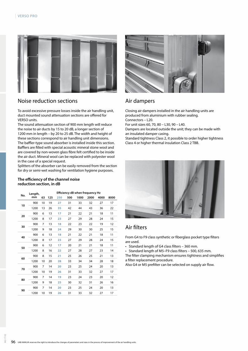
96
VERSO PRO
63 125 250 500 1000 2000 4000 8000
10900 10 19 27 31 33 32 27 17
1200 13 26 35 42 44 43 36 22
20900 6 13 17 21 22 21 18 11
1200 8 17 23 27 29 28 24 15
30900 7 13 18 22 23 22 19 12
1200 9 18 24 29 30 30 25 15
40900 6 13 18 21 22 21 18 11
1200 8 17 23 27 29 28 24 15
50900 6 12 17 20 21 21 18 11
1200 8 16 22 27 28 27 23 14
60900 8 15 21 25 26 25 21 13
1200 10 20 28 33 34 34 28 18
70900 7 14 20 23 25 24 20 13
1200 10 19 26 31 33 32 27 17
80900 7 14 19 23 24 23 20 12
1200 9 18 25 30 32 31 26 16
90900 7 14 20 23 25 24 20 13
1200 10 19 26 31 33 32 27 17
UAB AMALVA reserves the right to introduce the changes of parameters and sizes in the process of improvement of the air handling units.KK2-
17-0
2
air dampers
Closing air dampers installed in the air handling units are produced from aluminium with rubber sealing.Connectors – L20.For unit sizes 60, 70, 80 – L30, 90 – L40.Dampersarelocatedoutsidetheunit;theycanbemadewithan insulated damper casing.Standard tightness Class 2, it possible to order higher tightness Class4orhigherthermalinsulationClass2TBB.
Noise reduction sections
to avoid excessive pressure losses inside the air hand ling unit, duct mounted sound attenuation sections are offered for VERSO units.the sound attenuation section of 900 mm length will reduce thenoisetoairductsby15to20dB,alongersectionof1200mminlength–by20to25dB.Thewidthandheightofthese sections correspond to air handling unit dimensions.the baffler-type sound absorber is installed inside this section. Bafflersarefilledwithspecialacousticmineralstonewoolandare covered by non-woven glass fibre felt certified to be inside the air duct. Mineral wool can be replaced with polyester wool in the case of a special request.Splitters of the absorber can be easily removed from the section for dry or semi-wet washing for ventilation hygiene purposes.
air filters
From G4 to F9 class synthetic or fiberglass pocket type filters are used.• Standard length of G4 class filters – 360 mm.• Standard length of M5–F9 class filters – 500, 635 mm.the filter clamping mechanism ensures tightness and simp lifies a filter replacement procedure.also G4 or M5 prefilter can be selected on supply air flow.
The efficiency of the channel noise reduction section, in dB
No. Length, mm
Efficiency dB when frequency Hz

97
VERSO PRO
All data can be calculated in VERSO selection software. If data of performance do not correspond to data in selection software, please refer to data shown in software. KK2-
17-0
2
Casing and outside grilles
Casing and outside grilles can be additionally mounted on the supply and exhaust vents of outdoor air handling units.
Roof
a roof with water drainage must be additionally installed on outdoor air handling units.
Height adjustable feet
the construction frame of the air handling unit with height adjustable feet makes it much easier to level the unit on the site.
Inspection window and lighting
Internal lighting enables to observe unit‘s internal operation through inspection window. Economy light is used with switch outside the unit.
Inspection window enables to observe unit‘s internal operation. the diameter of plastic window is 200 mm.
door locks and handles
Easy to use door locks and handles ensure safe unit main-tenance.

98
VERSO PRO
Verso R
L1.1 L1.2 L1.3 L1.1
b ×
hB×H
a
b ×
hb
× h
Verso P
L1.1 L1.2 L1.2 L1.1
B×H
a
L1.3
b ×
hb
× h
b ×
h
Size B H L1.1 L1.2 L1.3 b h A10 1000 1000 618 370 435 700 300 125
20 1150 1150 751 370 435 900 400 125
30 1300 1300 751 370 435 1000 500 125
40 1500 1520 751 390 435 1200 600 125
50 1700 1715 885 390 435 1400 700 125
60 1900 1920 885 390 570 1600 800 125
70 2100 2100 885 390 705 1800 900 125
80 2300 2420 1250 510 841 2000 1000 125
90 2610 2650 1400 550 1040 2200 1100 125
Size B H L1.1 L1.2 L1.3 b h A10 1000 1000 618 422 435 700 300 125
20 1150 1150 751 570 435 900 400 125
30 1300 1300 751 570 435 1000 500 125
40 1500 1520 751 570 435 1200 600 125
50 1700 1715 885 707 435 1400 700 125
60 1900 1920 885 845 570 1600 800 125
70 2100 2100 885 845 705 1800 900 125
80 2300 2420 1250 1150 841 2000 1000 125
90 2610 2650 1400 1150 1040 2200 1100 125
Verso CF
L1.1 L1.2 L1.2 L1.1L1.3
b ×
h
b ×
hb
× h
B×H
a
Size B H L1.1 L1.2 L1.3 L3 b h A10 1000 1000 618 570 435 710 700 300 125
20 1150 1150 751 645 435 710 900 400 125
30 1300 1300 751 720 435 710 1000 500 125
40 1500 1520 751 720 435 710 1200 600 125
50 1700 1715 885 720 435 710 1400 700 125
60 1900 1920 885 920 570 710 1600 800 125
70 2100 2100 885 1060 705 710 1800 900 125
80 2300 2420 1250 1250 841 710 2000 1000 125
90 2610 2650 1400 1250 1040 710 2200 1100 125
Verso S
L1.4 L1.1 L1.2
b2 × h2
B ×
Ha
b ×
h
b ×
h
Size B H L1.1 L1.2 L1.4 b h b1 h1 b2 h2 A10 1000 490 750 705 430 900 400 700 300 700 300 125
20 1150 585 750 705 430 1100 500 900 400 1000 300 125
30 1300 660 750 705 470 1200 600 1000 500 1100 400 125
40 1500 740 750 842 470 1400 700 1200 600 1200 400 125
50 1700 890 750 842 470 1600 800 1400 700 1400 400 125
60 1900 960 750 979 570 1800 900 1600 800 1600 500 125
70 2100 1085 750 979 705 2000 1000 1800 900 1800 600 125
80 2300 1235 750 1250 705 2200 1100 2000 1000 2000 600 125
90 2610 1350 750 1400 705 2500 1200 2200 1100 2200 600 125
UAB AMALVA reserves the right to introduce the changes of parameters and sizes in the process of improvement of the air handling units.KK2-
17-0
2
dimensionsModern air handling unit proportions allow reaching better technical parameters: a lower air flow velocity inside the unit, better acoustic data.
Note: the electric air heaters, water heaters and coolers section length and configuration are noted in the selection program of VERSO air handling units.
Notes: size 20÷70 plate heat exchanger section is made of two parts. Size 10, 80 and 90 – of one part. the electric air heaters, water heaters and coolers section length and configuration are noted in the selection program of VERSO air handling units.
Notes: size 20÷70 plate heat exchanger section is made of two parts. Size 10, 80 and 90 – of one part. the electric air heater section length is noted in the selection program of VERSO air handling units.
Note: the electric air heaters, water heaters and coolers section length and configuration are noted in the selection program of VERSO air handling units.
RHPVentilation units with heat pump
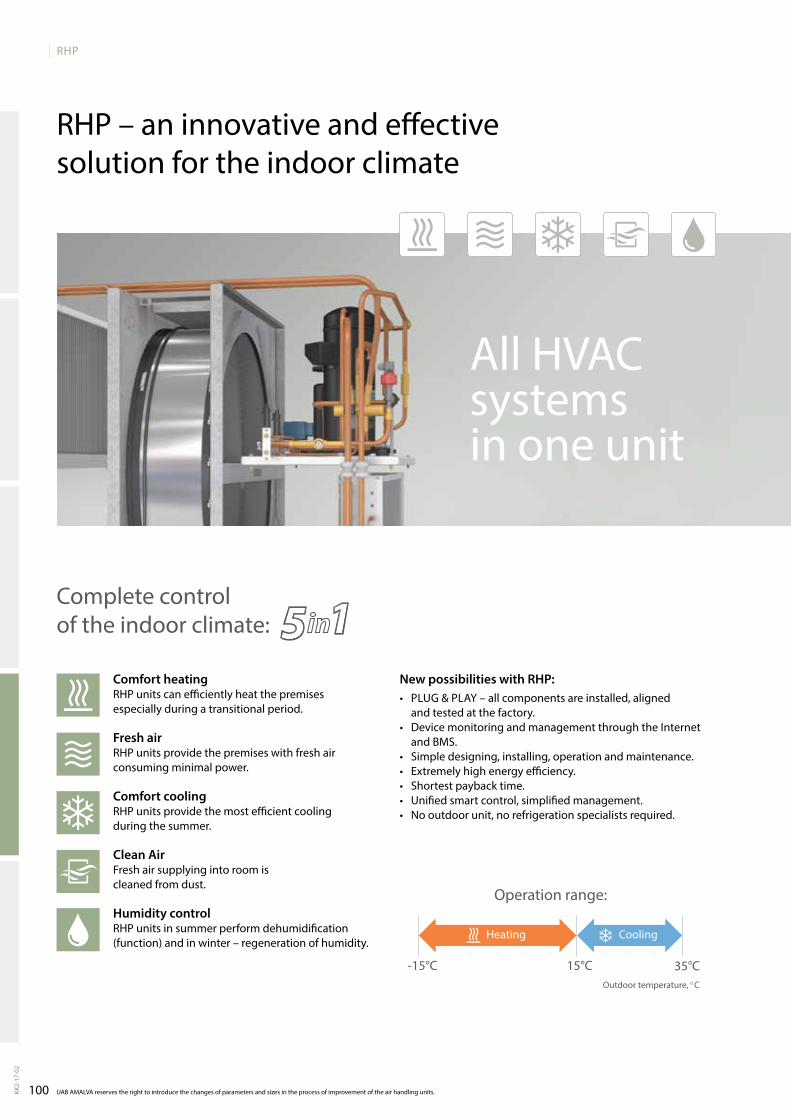
100
RHP
-15°C 15°C 35°C
UAB AMALVA reserves the right to introduce the changes of parameters and sizes in the process of improvement of the air handling units.KK2-
17-0
2
RHP – an innovative and effective solution for the indoor climate
Comfort heatingRHP units can efficiently heat the premises especially during a transitional period.
Fresh airRHP units provide the premises with fresh air consuming minimal power.
Comfort coolingRHP units provide the most efficient cooling during the summer.
Clean AirFresh air supplying into room is cleaned from dust.
Humidity controlRHP units in summer perform dehumidification (function) and in winter – regeneration of humidity.
All HVAC systems in one unit
Complete control of the indoor climate:
New possibilities with RHP:• Plug & PlAy – all components are installed, aligned
and tested at the factory.• DevicemonitoringandmanagementthroughtheInternet
and BMS.• Simpledesigning,installing,operationandmaintenance.• Extremelyhighenergyefficiency.• Shortestpaybacktime.• Unifiedsmartcontrol,simplifiedmanagement.• Nooutdoorunit,norefrigerationspecialistsrequired.
Operation range:
Outdoor temperature, °C
Heating Cooling
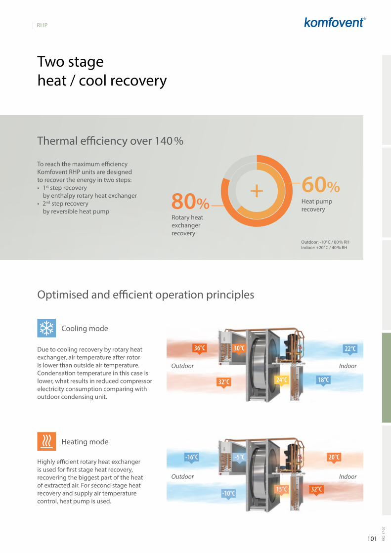
101
RHP
22°C
18°C24°C
36°C
32°C
30°C
-16°C
-10°C
-5°C 20°C
32°C15°C
80%60%
KK2-
17-0
2
Two stage heat / cool recovery
Thermal efficiency over 140 %
To reach the maximum efficiency Komfovent RHP units are designed to recover the energy in two steps:• 1st step recovery
by enthalpy rotary heat exchanger• 2nd step recovery
by reversible heat pumpRotary heat exchanger recovery
Heat pump recovery
Outdoor: -10° C / 80 % RH Indoor: +20° C / 40 % RH
Due to cooling recovery by rotary heat exchanger, air temperature after rotor is lower than outside air temperature. Condensation temperature in this case is lower, what results in reduced compressor electricity consumption comparing with outdoor condensing unit.
Cooling mode
IndoorOutdoor
IndoorOutdoor
Highly efficient rotary heat exchanger is used for first stage heat recovery, recovering the biggest part of the heat of extracted air. For second stage heat recovery and supply air temperature control, heat pump is used.
Heating mode
Optimised and efficient operation principles
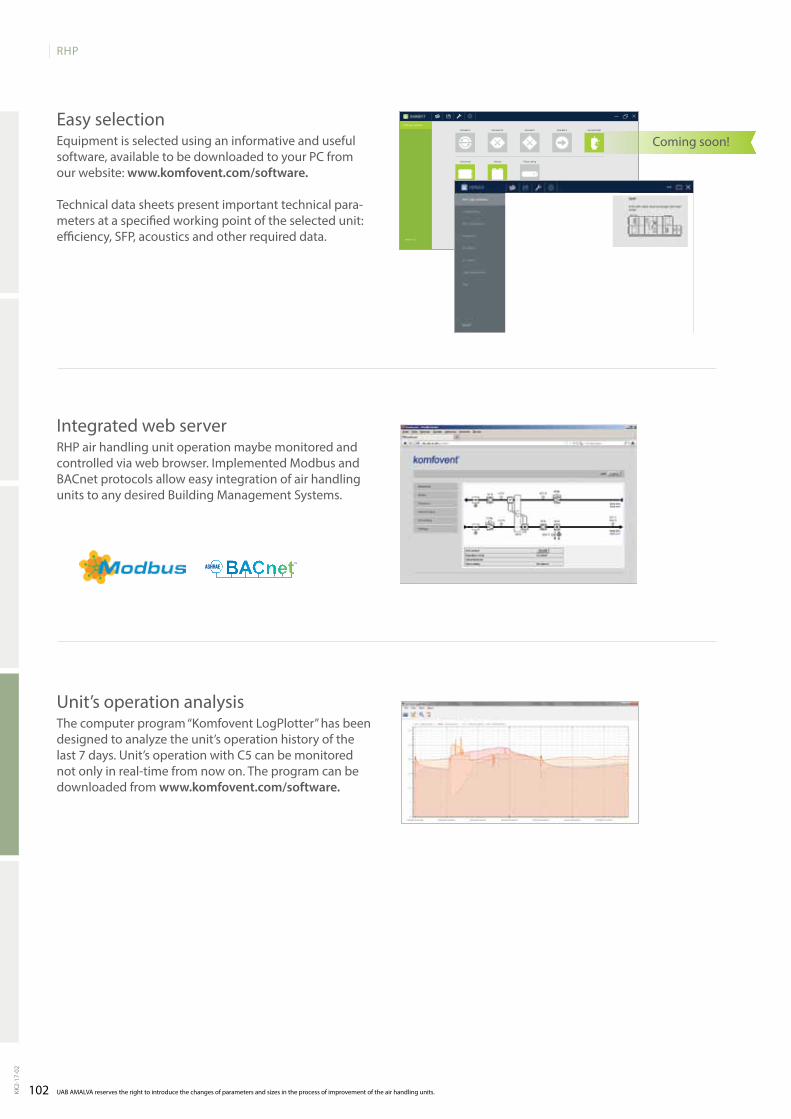
102
RHP
Horizontal
Electric heater
Domekt P
Vertical
Water heater None
Domekt CF
False ceiling
Domekt S Domekt RHPDomekt R
AHU type selection
Version 1.5.2
UAB AMALVA reserves the right to introduce the changes of parameters and sizes in the process of improvement of the air handling units.KK2-
17-0
2
EasyselectionEquipmentisselectedusinganinformativeandusefulsoftware,availabletobedownloadedtoyourPCfromourwebsite:www.komfovent.com/software.
Technical data sheets present important technical para-metersataspecifiedworkingpointoftheselectedunit:efficiency,SFP,acousticsandotherrequireddata.
IntegratedwebserverRHPairhandlingunitoperationmaybemonitoredandcontrolledviawebbrowser.ImplementedModbusandBACnet protocols allow easy integration of air handling units to any desired Building Management Systems.
unit’s operation analysisThecomputerprogram“KomfoventLogPlotter”hasbeendesigned to analyze the unit’s operation history of the last7days.Unit’soperationwithC5canbemonitorednotonlyinreal-timefromnowon.Theprogramcanbedownloaded from www.komfovent.com/software.
Coming soon!
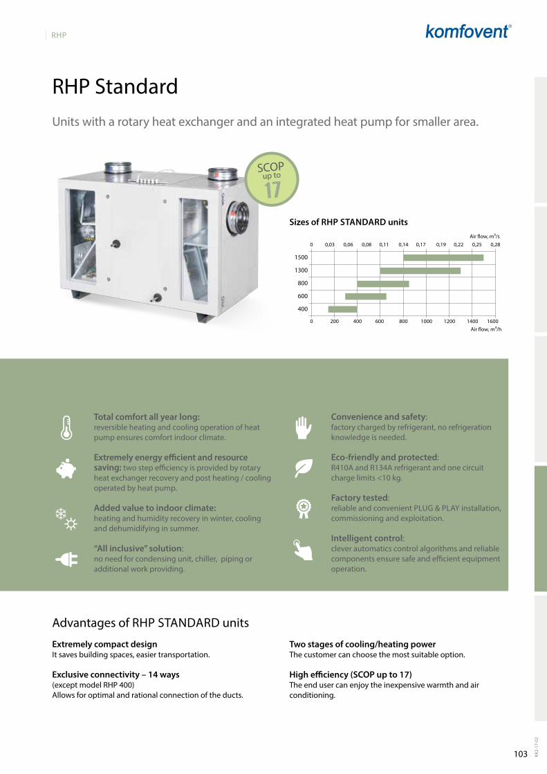
103
RHP
0 200 400 600 800 1000 1200 1400 1600
0 0,03 0,06 0,08 0,11 0,14 0,17 0,19 0,22 0,25 0,28
1500
1300
800
600
400
RHP Standard
KK2-
17-0
2
Sizes of RHP StANdARd unitsAir flow, m³/s
Air flow, m³/h
17
Unitswitharotaryheatexchangerandanintegratedheatpumpforsmallerarea.
Total comfort all year long: reversible heating and cooling operation of heat pump ensures comfort indoor climate.
Extremely energy efficient and resource saving: two step efficiency is provided by rotary heat exchanger recovery and post heating / cooling operated by heat pump.
Added value to indoor climate: heating and humidity recovery in winter, cooling and dehumidifying in summer.
“All inclusive” solution: no need for condensing unit, chiller, piping or additional work providing.
Why to choose RHP StandaRd units
Convenience and safety: factorychargedbyrefrigerant,norefrigerationknowledgeisneeded.
Eco-friendly and protected: R410A and R134A refrigerant and one circuit chargelimits<10kg.
Factory tested: reliableandconvenientPlug & PlAy installation, commissioningandexploitation.
Intelligent control: cleverautomaticscontrolalgorithmsandreliable componentsensuresafeandefficientequipmentoperation.
SCOPup to
Advantages of RHPSTaNDaRD units
Extremely compact designItsavesbuildingspaces,easiertransportation.
Exclusive connectivity – 14 ways(exceptmodelRHP400)Allows for optimal and rational connection of the ducts.
two stages of cooling/heating powerThecustomercanchoosethemostsuitableoption.
High efficiency (SCOP up to 17)Theendusercanenjoytheinexpensivewarmthandairconditioning.

104
RHP Standard
RHP 400 V
53
66
51
66
40
30
395
30/50
120
1~230
6,6 (RHP 2.2/1.4)
7,7 (RHP 2.8/2.4)
80
0,077
50
0,21
462×200×46-M5
60
96
1 / 7,5
C5.1
720
A+
395 m³/h40
1042
1015
892
123
712
447
160 (4×)
135
210
168
240
130
371212 131
168
249
618
502
618
DA D CB C B A
B
CD
A
400
300
200
100
00 100 200 300 400 500
0 0,02 0,04 0,06 0,08 0,1 0,12
SPI0,14
SPI0,21
SPI0,28
SPI0,35
RHP 2.2/1.4
RHP 2.8/2.4
C5.1
R134A
RHP 2.2/1.4 0,9
RHP 2.8/2.4 1,8
10,8 12,8 14 15,3 16,5 22,7 24 25,2
The
phot
o is
inte
nded
for i
nfor
mat
iona
l pur
pose
s on
ly, e
xact
det
ails
may
var
y.
Acoustic dataA-weighted sound power level LwA, dB(A)at reference flow rate
Supply inlet
Supply outlet
Exhaust inlet
Exhaust outlet
Casing
A-weighted sound pressure level LPA, dB(A) 10 m² normally isolated room, distance from casing – 3 m.
Surroundings
Maximal air flow, m³/h
Panel thickness, mm
Unit weight, kg
Supply voltage, V
Maximal operating current, A
Maximal operating current, A
Thermal efficiency of heat recovery, %
Reference flow rate, m³/s
Reference pressure difference, Pa
SPI, W/(m³/h)
Filters dimensions B×H×L, mm
Electric power input of the fan drive at reference flow rate, W
Electric power input of the fan drive at maximum flow rate, W
Electric air heater capacity, kW / ∆t, °C
Control panel
Maintenance space, mm
Compressor and AHU dataRefrigerant
Compressor heating capacity, kW
104KK2-
17-0
2
UAB AMALVA reserves the right to introduce the changes of parameters and sizes in the process of improvement of the air handling units. If data of performance do not correspond to data in the selection software, please refer to data shown in software.
Accessories
Closing damper
SilencerA/D
B/C
Temperature efficiencyWinter Summer
Outside temperature, °C -23 -15 -10 -5 0 25 30 35
After heat exchanger*, °C
* indoor +22°C, 20 % RH
Stat
ic p
ress
ure
(Pa)
Shown as right (R1)
A outdoorintakeB supply airC extractindoord exhaustair
Heat pump operating area:
AguJ-M-160+lM24
AgS-160-50-600-M
AgS-160-50-900-M
PerformanceFilterM5,rotaryheatexchangerXL, heat pump system and electric air heater.
Air flow rate (m3/s)
Air flow rate (m3/h)
Theunitisavailableonlyright inspection side.
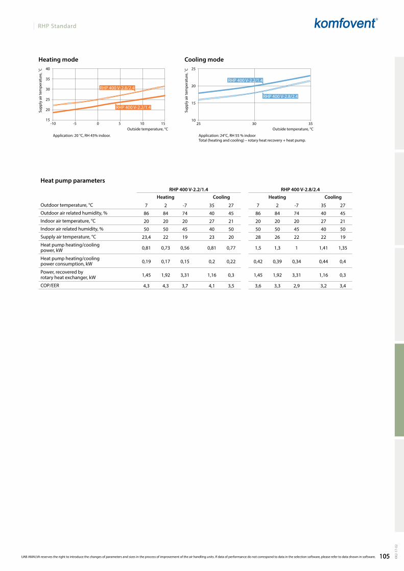
105
RHP Standard
40
35
30
25
20
15-10 -5 0 5 10 15
25
20
15
1025 30 35
RHP 400 V-2.2/1.4 RHP 400 V-2.8/2.4
7 2 -7 35 27 7 2 -7 35 27
86 84 74 40 45 86 84 74 40 45
20 20 20 27 21 20 20 20 27 21
50 50 45 40 50 50 50 45 40 50
23,4 22 19 23 20 28 26 22 22 19
0,81 0,73 0,56 0,81 0,77 1,5 1,3 1 1,41 1,35
0,19 0,17 0,15 0,2 0,22 0,42 0,39 0,34 0,44 0,4
1,45 1,92 3,31 1,16 0,3 1,45 1,92 3,31 1,16 0,3
4,3 4,3 3,7 4,1 3,5 3,6 3,3 2,9 3,2 3,4
RHP 400 V-2.2/1.4
RHP 400 V-2.8/2.4
RHP 400 V-2.8/2.4
RHP 400 V-2.2/1.4
Application: 20 °C, RH 45% indoor. Application: 24°C, RH 55 % indoorTotal (heating and cooling) – rotary heat recovery + heat pump.
Outside temperature, °COutside temperature, °C
Cooling modeHeating mode
Supp
ly a
ir te
mpe
ratu
re, ˚
C
Supp
ly a
ir te
mpe
ratu
re, ˚
C
105 KK2-
17-0
2
UAB AMALVA reserves the right to introduce the changes of parameters and sizes in the process of improvement of the air handling units. If data of performance do not correspond to data in the selection software, please refer to data shown in software.
Heat pump parameters
Heating Cooling Heating Cooling
Outdoor temperature, °C
Outdoor air related humidity, %
Indoor air temperature, °C
Indoor air related humidity, %
Supply air temperature, °C
Heat pump heating/cooling power, kW
Heat pump heating/cooling power consumption, kW
Power, recovered by rotary heat exchanger, kW
COP/EER

106
RHP Standard
RHP 600 U
53
65
52
62
40
29
650
50
194
1~230
9,6 (RHP 3.7/3)
10,5 (RHP 4.4/3.8)
83
0,13
50
0,32
500×280×46-M5
70
170
1 / 6
C5.1
600
R134A
RHP 3.7/3 1,8
RHP 4.4/3.8 2,8
410 195438
433 12541400 650
200 (4×)
200
292
610
610
805
894
С
DB
A
1066200
188
456
650
A
D
C
BB
C
D
D
C
A
B
A
B
D
A
C
200 (4×)
BA
CD
D=15mm
AguJ-M-200+lM24
AgS-200-50-600-M
AgS-200-50-900-M
0 100 200 300 400 500 600 700 800
500
400
300
200
100
0
SPI0,14
SPI0,21
SPI0,28
SPI0,35
A+
650 m³/h40
C5.1
14,1 15,5 16,4 17,3 18,2 22,5 23,4 24,3
The
phot
o is
inte
nded
for i
nfor
mat
iona
l pur
pose
s on
ly, e
xact
det
ails
may
var
y.
Acoustic dataA-weighted sound power level LwA, dB(A)at reference flow rate
Supply inlet
Supply outlet
Exhaust inlet
Exhaust outlet
Casing
A-weighted sound pressure level LPA, dB(A) 10 m² normally isolated room, distance from casing – 3 m.
Surroundings
Maximal air flow, m³/h
Panel thickness, mm
Unit weight, kg
Supply voltage, V
Maximal operating current, A
Maximal operating current, A
Thermal efficiency of heat recovery, %
Reference flow rate, m³/s
Reference pressure difference, Pa
SPI, W/(m³/h)
Filters dimensions B×H×L, mm
Electric power input of the fan drive at reference flow rate, W
Electric power input of the fan drive at maximum flow rate, W
Electric air heater capacity, kW / ∆t, °C
Control panel
Maintenance space, mm
Compressor and AHU dataRefrigerant
Compressor heating capacity, kW
Stat
ic p
ress
ure
(Pa)
Air flow rate (m3/s)
Air flow rate (m3/h)
PerformanceFilterM5,rotaryheatexchangerL, heat pump system and electric air heater.
106KK2-
17-0
2
UAB AMALVA reserves the right to introduce the changes of parameters and sizes in the process of improvement of the air handling units. If data of performance do not correspond to data in the selection software, please refer to data shown in software.
Accessories
Closing damper
SilencerA/D
B/C
Temperature efficiencyWinter Summer
Outside temperature, °C -23 -15 -10 -5 0 25 30 35
After heat exchanger*, °C
* indoor +22°C, 20 % RH
Shown as right (R1)
Shown as left (L1) A outdoorintakeB supply airC extractindoord exhaustair
Heat pump operating area:
RHP 3.7/3
RHP 4.4/3.8
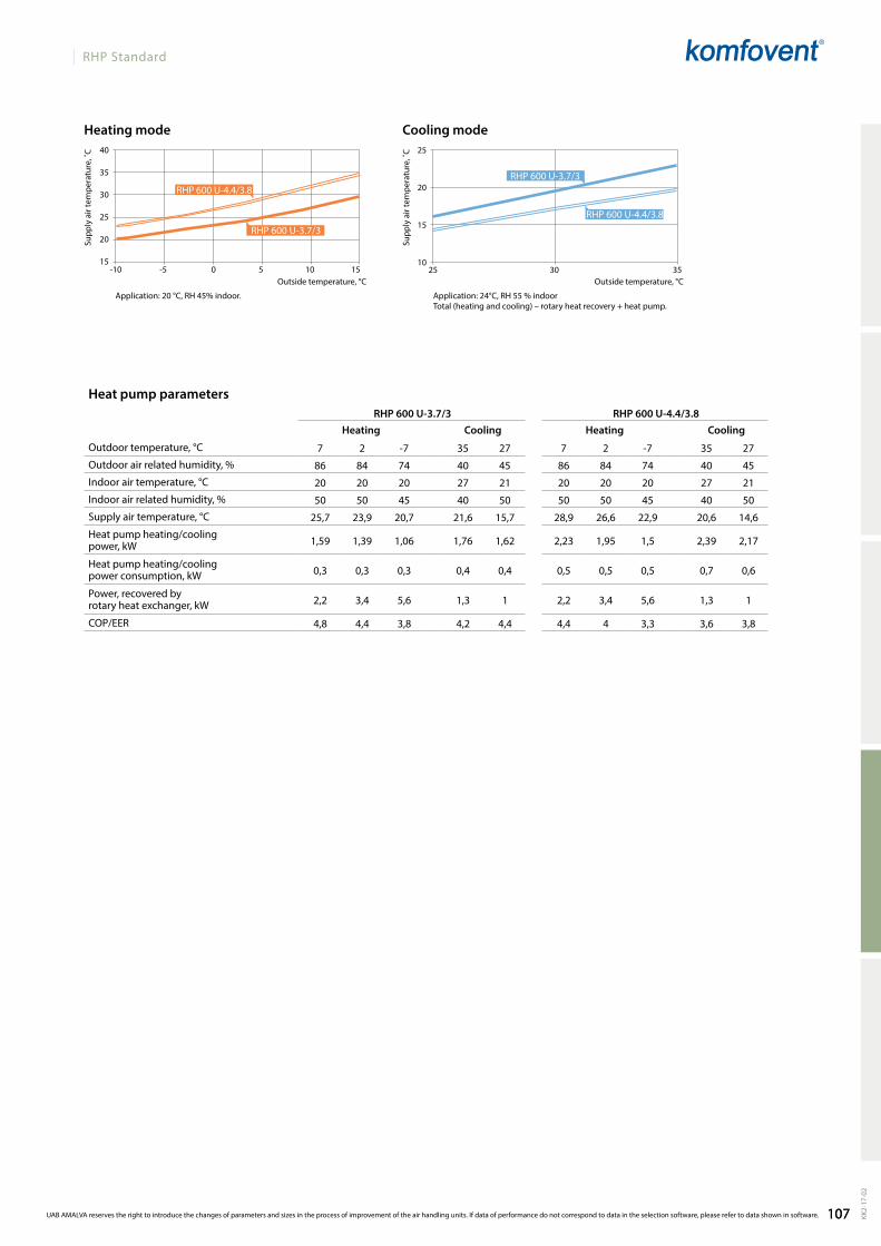
107
RHP Standard
40
35
30
25
20
15-10 -5 0 5 10 15
25
20
15
1025 30 35
RHP 600 U-3.7/3 RHP 600 U-4.4/3.8
7 2 -7 35 27 7 2 -7 35 27
86 84 74 40 45 86 84 74 40 45
20 20 20 27 21 20 20 20 27 21
50 50 45 40 50 50 50 45 40 50
25,7 23,9 20,7 21,6 15,7 28,9 26,6 22,9 20,6 14,6
1,59 1,39 1,06 1,76 1,62 2,23 1,95 1,5 2,39 2,17
0,3 0,3 0,3 0,4 0,4 0,5 0,5 0,5 0,7 0,6
2,2 3,4 5,6 1,3 1 2,2 3,4 5,6 1,3 1
4,8 4,4 3,8 4,2 4,4 4,4 4 3,3 3,6 3,8
RHP 600 u-4.4/3.8
RHP 600 u-3.7/3
RHP 600 u-3.7/3
RHP 600 u-4.4/3.8
Application: 20 °C, RH 45% indoor. Application: 24°C, RH 55 % indoorTotal (heating and cooling) – rotary heat recovery + heat pump.
Outside temperature, °COutside temperature, °C
Cooling modeHeating mode
Supp
ly a
ir te
mpe
ratu
re, ˚
C
Supp
ly a
ir te
mpe
ratu
re, ˚
C
107 KK2-
17-0
2
UAB AMALVA reserves the right to introduce the changes of parameters and sizes in the process of improvement of the air handling units. If data of performance do not correspond to data in the selection software, please refer to data shown in software.
Heat pump parameters
Heating Cooling Heating Cooling
Outdoor temperature, °C
Outdoor air related humidity, %
Indoor air temperature, °C
Indoor air related humidity, %
Supply air temperature, °C
Heat pump heating/cooling power, kW
Heat pump heating/cooling power consumption, kW
Power, recovered by rotary heat exchanger, kW
COP/EER

108
RHP Standard
RHP 800 U
A+
850 m³/h41
53
64
51
61
41
31
850
50
255
3~400
14,8 (RHP 5.3/4.7)
16,1 (RHP 6.1/5.8)
87
0,17
50
0,24
750×400×46-M5
70
170
2 / 7
C5.1
800
R134A
RHP 5.3/4.7 2,8
RHP 6.1/5.8 3,9
252200650
543 15051648
905850
250 (4×)
250 (4×)
264
242
662
692
905
986
С A
B D
238237
231
235
595
650
905
905
BA
CD
A
D
C
BB
C
D
D
C
A
B
A
B
D
A
C
D=15mm
AguJ-M-250+lM24
AgS-250-50-600-M
AgS-250-50-900-M
0 200 400 600 800 1000 1200
400
300
200
100
0
0 0,05 0,1 0,15 0,2 0,25 0,3
SPI0,14
SPI0,21
SPI0,28
SPI0,35
C5.1
14,1 15,2 15,9 16,6 17,3 22,4 23,1 23,8
The
phot
o is
inte
nded
for i
nfor
mat
iona
l pur
pose
s on
ly, e
xact
det
ails
may
var
y.
Acoustic dataA-weighted sound power level LwA, dB(A)at reference flow rate
Supply inlet
Supply outlet
Exhaust inlet
Exhaust outlet
Casing
A-weighted sound pressure level LPA, dB(A) 10 m² normally isolated room, distance from casing – 3 m.
Surroundings
Maximal air flow, m³/h
Panel thickness, mm
Unit weight, kg
Supply voltage, V
Maximal operating current, A
Maximal operating current, A
Thermal efficiency of heat recovery, %
Reference flow rate, m³/s
Reference pressure difference, Pa
SPI, W/(m³/h)
Filters dimensions B×H×L, mm
Electric power input of the fan drive at reference flow rate, W
Electric power input of the fan drive at maximum flow rate, W
Electric air heater capacity, kW / ∆t, °C
Control panel
Maintenance space, mm
Compressor and AHU dataRefrigerant
Compressor heating capacity, kW
Stat
ic p
ress
ure
(Pa)
Air flow rate (m3/s)
Air flow rate (m3/h)
PerformanceFilterM5,rotaryheatexchangerL, heat pump system and electric air heater.
108KK2-
17-0
2
UAB AMALVA reserves the right to introduce the changes of parameters and sizes in the process of improvement of the air handling units. If data of performance do not correspond to data in the selection software, please refer to data shown in software.
Accessories
Closing damper
SilencerA/D
B/C
Temperature efficiencyWinter Summer
Outside temperature, °C -23 -15 -10 -5 0 25 30 35
After heat exchanger*, °C
* indoor +22°C, 20 % RH
Shown as right (R1)
Shown as left (L1) A outdoorintakeB supply airC extractindoord exhaustair
Heat pump operating area:
RHP 5.3/4.7
RHP 6.1/5.8
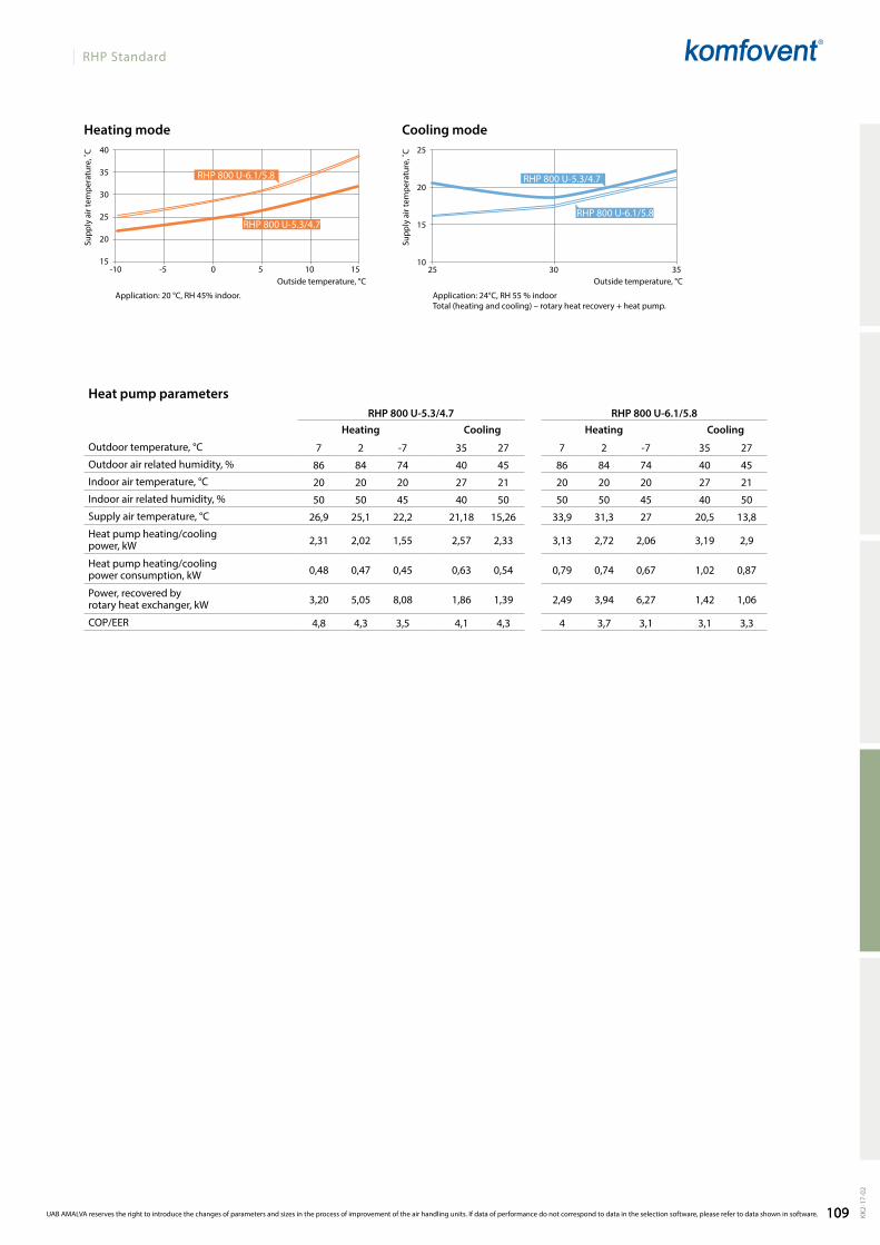
109
RHP Standard
40
35
30
25
20
15-10 -5 0 5 10 15
25
20
15
1025 30 35
RHP 800 U-5.3/4.7 RHP 800 U-6.1/5.8
7 2 -7 35 27 7 2 -7 35 27
86 84 74 40 45 86 84 74 40 45
20 20 20 27 21 20 20 20 27 21
50 50 45 40 50 50 50 45 40 50
26,9 25,1 22,2 21,18 15,26 33,9 31,3 27 20,5 13,8
2,31 2,02 1,55 2,57 2,33 3,13 2,72 2,06 3,19 2,9
0,48 0,47 0,45 0,63 0,54 0,79 0,74 0,67 1,02 0,87
3,20 5,05 8,08 1,86 1,39 2,49 3,94 6,27 1,42 1,06
4,8 4,3 3,5 4,1 4,3 4 3,7 3,1 3,1 3,3
RHP 800 u-6.1/5.8
RHP 800 u-5.3/4.7
RHP 800 u-5.3/4.7
RHP 800 u-6.1/5.8
Application: 20 °C, RH 45% indoor. Application: 24°C, RH 55 % indoorTotal (heating and cooling) – rotary heat recovery + heat pump.
Outside temperature, °COutside temperature, °C
Cooling modeHeating mode
Supp
ly a
ir te
mpe
ratu
re, ˚
C
Supp
ly a
ir te
mpe
ratu
re, ˚
C
109 KK2-
17-0
2
UAB AMALVA reserves the right to introduce the changes of parameters and sizes in the process of improvement of the air handling units. If data of performance do not correspond to data in the selection software, please refer to data shown in software.
Heat pump parameters
Heating Cooling Heating Cooling
Outdoor temperature, °C
Outdoor air related humidity, %
Indoor air temperature, °C
Indoor air related humidity, %
Supply air temperature, °C
Heat pump heating/cooling power, kW
Heat pump heating/cooling power consumption, kW
Power, recovered by rotary heat exchanger, kW
COP/EER
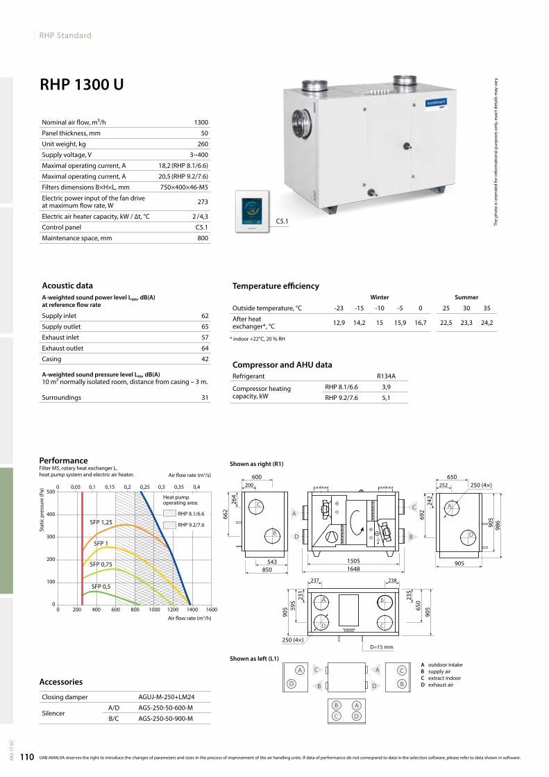
110
RHP Standard
RHP 1300 U
1300
50
260
3~400
18,2 (RHP 8.1/6.6)
20,5 (RHP 9.2/7.6)
750×400×46-M5
273
2 / 4,3
C5.1
800
62
65
57
64
42
31
0 200 400 600 800 1000 1200 1400 1600
500
400
300
200
100
0
SFP 1,25
SFP 1
SFP 0,75
SFP 0,5
0 0,05 0,1 0,15 0,2 0,25 0,3 0,35 0,4
R134A
RHP 8.1/6.6 3,9
RHP 9.2/7.6 5,1
252200650600
543 15051648
905850
250 (4×)
250 (4×)
264
242
662
692
905
986
С A
B D
238237
231
235
595
650
905
905
BA
CD
A
D
C
BB
C
D
A C
A
B
B
D
A
C
D=15mm
D
AguJ-M-250+lM24
AgS-250-50-600-M
AgS-250-50-900-M
C5.1
12,9 14,2 15 15,9 16,7 22,5 23,3 24,2
The
phot
o is
inte
nded
for i
nfor
mat
iona
l pur
pose
s on
ly, e
xact
det
ails
may
var
y.
Acoustic dataA-weighted sound power level LwA, dB(A)at reference flow rate
Supply inlet
Supply outlet
Exhaust inlet
Exhaust outlet
Casing
A-weighted sound pressure level LPA, dB(A) 10 m² normally isolated room, distance from casing – 3 m.
Surroundings
Compressor and AHU dataRefrigerant
Compressor heating capacity, kW
Stat
ic p
ress
ure
(Pa)
Air flow rate (m3/s)
Air flow rate (m3/h)
PerformanceFilterM5,rotaryheatexchangerL, heat pump system and electric air heater.
110KK2-
17-0
2
UAB AMALVA reserves the right to introduce the changes of parameters and sizes in the process of improvement of the air handling units. If data of performance do not correspond to data in the selection software, please refer to data shown in software.
Nominal air flow, m³/h
Panel thickness, mm
Unit weight, kg
Supply voltage, V
Maximal operating current, A
Maximal operating current, A
Filters dimensions B×H×L, mm
Electric power input of the fan drive at maximum flow rate, W
Electric air heater capacity, kW / ∆t, °C
Control panel
Maintenance space, mm
Accessories
Closing damper
SilencerA/D
B/C
Temperature efficiencyWinter Summer
Outside temperature, °C -23 -15 -10 -5 0 25 30 35
After heat exchanger*, °C
* indoor +22°C, 20 % RH
Heat pump operating area:
RHP 8.1/6.6
RHP 9.2/7.6
A outdoorintakeB supply airC extractindoord exhaustair
Shown as right (R1)
Shown as left (L1)
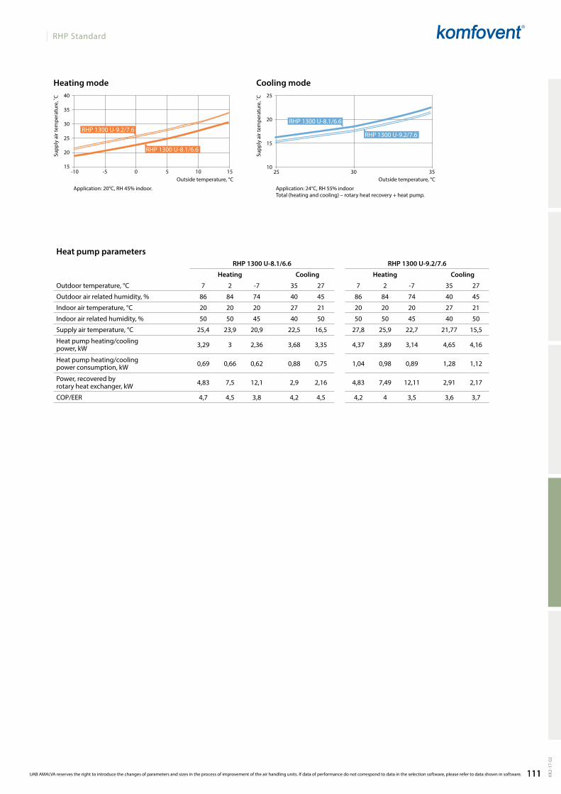
111
RHP Standard
40
35
30
25
20
15
25
20
15
1025 30 35
RHP 1300 U-8.1/6.6 RHP 1300 U-9.2/7.6
7 2 -7 35 27 7 2 -7 35 27
86 84 74 40 45 86 84 74 40 45
20 20 20 27 21 20 20 20 27 21
50 50 45 40 50 50 50 45 40 50
25,4 23,9 20,9 22,5 16,5 27,8 25,9 22,7 21,77 15,5
3,29 3 2,36 3,68 3,35 4,37 3,89 3,14 4,65 4,16
0,69 0,66 0,62 0,88 0,75 1,04 0,98 0,89 1,28 1,12
4,83 7,5 12,1 2,9 2,16 4,83 7,49 12,11 2,91 2,17
4,7 4,5 3,8 4,2 4,5 4,2 4 3,5 3,6 3,7
RHP 1300 u-8.1/6.6
RHP 1300 u-9.2/7.6RHP 1300 u-9.2/7.6
RHP 1300 u-8.1/6.6
-10 -5 0 5 10 15
Heat pump parameters
Heating Cooling Heating Cooling
Outdoor temperature, °C
Outdoor air related humidity, %
Indoor air temperature, °C
Indoor air related humidity, %
Supply air temperature, °C
Heat pump heating/cooling power, kW
Heat pump heating/cooling power consumption, kW
Power, recovered by rotary heat exchanger, kW
COP/EER
Application: 20°C, RH 45% indoor. Application: 24°C, RH 55% indoorTotal (heating and cooling) – rotary heat recovery + heat pump.
Outside temperature, °C
Cooling modeHeating mode
Supp
ly a
ir te
mpe
ratu
re, ˚
C
Supp
ly a
ir te
mpe
ratu
re, ˚
C
Outside temperature, °C
111 KK2-
17-0
2
UAB AMALVA reserves the right to introduce the changes of parameters and sizes in the process of improvement of the air handling units. If data of performance do not correspond to data in the selection software, please refer to data shown in software.
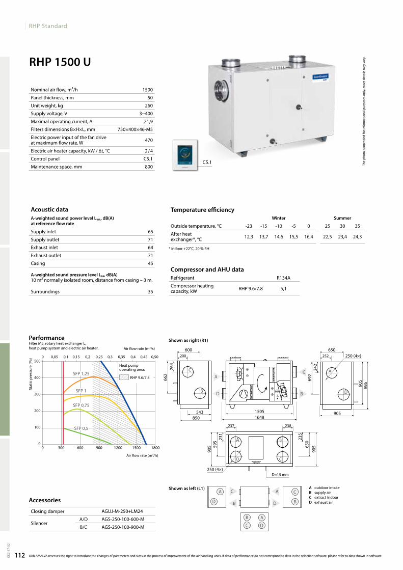
112
RHP Standard
RHP 1500 U
1500
50
260
3~400
21,9
750×400×46-M5
470
2 / 4
C5.1
800
65
71
64
71
45
35
0 300 600 900 1200 1500 1800
500
400
300
200
100
0
0 0,05 0,1 0,15 0,2 0,25 0,3 0,35 0,4 0,45 0,50
SFP 1,25
SFP 1
SFP 0,75
SFP 0,5
R134A
RHP 9.6/7.8 5,1
252200650600
543 15051648
905850
250 (4×)
250 (4×)
264
242
662
692
905
986
С A
B D
238237
231
235
595
650
905
905
BA
CD
A
D
C
BB
C
D
A C
A
B
B
D
A
C
D=15mm
D
AguJ-M-250+lM24
AgS-250-100-600-M
AgS-250-100-900-M
C5.1
12,3 13,7 14,6 15,5 16,4 22,5 23,4 24,3
The
phot
o is
inte
nded
for i
nfor
mat
iona
l pur
pose
s on
ly, e
xact
det
ails
may
var
y.
Stat
ic p
ress
ure
(Pa)
Air flow rate (m3/s)
Air flow rate (m3/h)
Acoustic dataA-weighted sound power level LwA, dB(A)at reference flow rate
Supply inlet
Supply outlet
Exhaust inlet
Exhaust outlet
Casing
A-weighted sound pressure level LPA, dB(A) 10 m² normally isolated room, distance from casing – 3 m.
Surroundings
Nominal air flow, m³/h
Panel thickness, mm
Unit weight, kg
Supply voltage, V
Maximal operating current, A
Filters dimensions B×H×L, mm
Electric power input of the fan drive at maximum flow rate, W
Electric air heater capacity, kW / ∆t, °C
Control panel
Maintenance space, mm
PerformanceFilter M5, rotary heat exchanger L, heat pump system and electric air heater.
112KK2-
17-0
2
UAB AMALVA reserves the right to introduce the changes of parameters and sizes in the process of improvement of the air handling units. If data of performance do not correspond to data in the selection software, please refer to data shown in software.
Accessories
Closing damper
SilencerA/D
B/C
Compressor and AHU dataRefrigerant
Compressor heating capacity, kW
Temperature efficiencyWinter Summer
Outside temperature, °C -23 -15 -10 -5 0 25 30 35
After heat exchanger*, °C
* indoor +22°C, 20 % RH
Heat pump operating area:
RHP 9.6/7.8
Shown as right (R1)
Shown as left (L1) A outdoorintakeB supply airC extractindoord exhaustair

113
RHP Standard
40
35
30
25
20
15
25
20
15
1025 30 35
RHP 1500 U 9.6/7.8
7 2 -7 35 27
86 84 74 40 45
20 20 20 27 21
50 50 45 40 50
27,2 25,2 22,1 21,9 15,7
4,4 3,9 3,2 4,7 4,2
1,0 1,0 0,9 1,3 1,1
5,2 7,9 12,8 3,1 2,3
4,3 4 3,6 3,7 3,8
RHP 1500 u-9.2/7.6
RHP 1500 u-9.2/7.6
-10 -5 0 5 10 15
Application: 20°C, RH 45% indoor. Application: 24°C, RH 55% indoorTotal (heating and cooling) – rotary heat recovery + heat pump.
Outside temperature, °COutside temperature, °C
Cooling modeHeating mode
Supp
ly a
ir te
mpe
ratu
re, ˚
C
Supp
ly a
ir te
mpe
ratu
re, ˚
CHeat pump parameters
Heating Cooling
Outdoor temperature, °C
Outdoor air related humidity, %
Indoor air temperature, °C
Indoor air related humidity, %
Supply air temperature, °C
Heat pump heating/cooling power, kW
Heat pump heating/cooling power consumption, kW
Power, recovered by rotary heat exchanger, kW
COP/EER
113 KK2-
17-0
2
UAB AMALVA reserves the right to introduce the changes of parameters and sizes in the process of improvement of the air handling units. If data of performance do not correspond to data in the selection software, please refer to data shown in software.
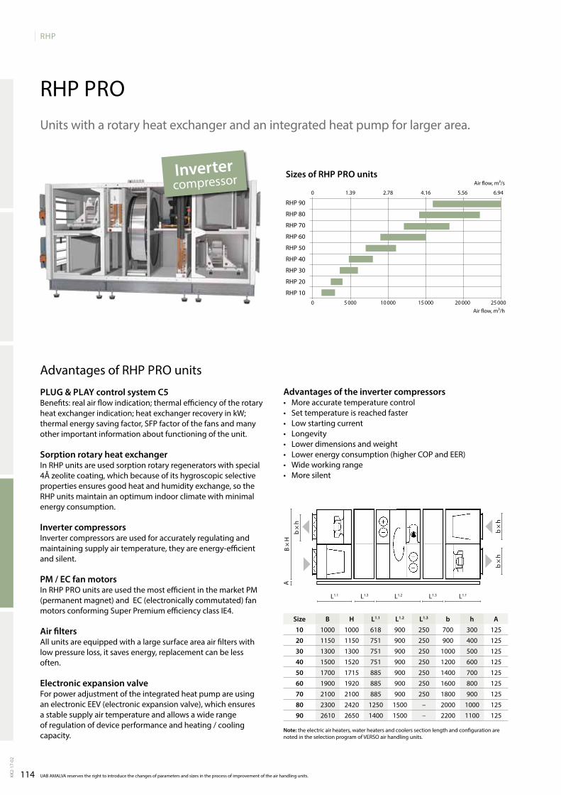
114
RHP
B H L1.1 L1.2 L1.3 b h A10 1000 1000 618 900 250 700 300 125
20 1150 1150 751 900 250 900 400 125
30 1300 1300 751 900 250 1000 500 125
40 1500 1520 751 900 250 1200 600 125
50 1700 1715 885 900 250 1400 700 125
60 1900 1920 885 900 250 1600 800 125
70 2100 2100 885 900 250 1800 900 125
80 2300 2420 1250 1500 – 2000 1000 125
90 2610 2650 1400 1500 – 2200 1100 125
0 5 000 10 000 15 000 20 000 25 000
0 1.39 2.78 4.16 5.56 6.94
RHP 90
RHP 80
RHP 70
RHP 60
RHP 50
RHP 40
RHP 30
RHP 20
RHP 10
UAB AMALVA reserves the right to introduce the changes of parameters and sizes in the process of improvement of the air handling units.KK2-
17-0
2
RHP PROUnitswitharotaryheatexchangerandanintegratedheatpumpforlargerarea.
Advantages of RHP PRO units
PLUg & PLAy control system C5Benefits: real air flow indication; thermal efficiency of the rotary heatexchangerindication;heatexchangerrecoveryinkW;thermal energy saving factor, SFP factor of the fans and many otherimportantinformationaboutfunctioningoftheunit.
Sorption rotary heat exchangerInRHPunitsareusedsorptionrotaryregeneratorswithspecial4Åzeolitecoating,whichbecauseofitshygroscopicselectivepropertiesensuresgoodheatandhumidityexchange,sotheRHP units maintain an optimum indoor climate with minimal energy consumption.
Inverter compressors Invertercompressorsareusedforaccuratelyregulatingandmaintaining supply air temperature, they are energy-efficient and silent.
PM / EC fan motorsInRHPPROunitsareusedthemostefficientinthemarketPM(permanentmagnet)andEC(electronicallycommutated)fanmotorsconformingSuperPremiumefficiencyclassIE4.
Air filtersallunitsareequippedwithalargesurfaceareaairfilterswithlowpressureloss,itsavesenergy,replacementcanbelessoften.
Electronic expansion valve For power adjustment of the integrated heat pump are using anelectronicEEV(electronicexpansionvalve),whichensuresastablesupplyairtemperatureandallowsawiderangeof regulation of device performance and heating / cooling capacity.
Sizes of RHP PRO unitsAir flow, m³/s
Air flow, m³/h
Note: the electric air heaters, water heaters and coolers section length and configuration are notedintheselectionprogramofVERSOairhandlingunits.
Size
Advantages of the inverter compressors• More accurate temperature control• Set temperature is reached faster• low starting current• longevity• lower dimensions and weight • Lowerenergyconsumption(higherCOPandEER)• Wideworkingrange• More silent
Inverter compressor
l1.1 l1.2l1.3 l1.3 l1.1
b×h
B ×
HA
b×h
b×h

KLASIKNon residential ventilation units
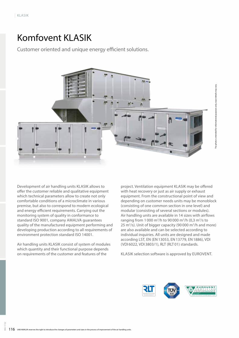
116
KLASIK
Range: KLASIKAHU No: 16.03.003
Komfovent KLASIK
UAB AMALVA reserves the right to introduce the changes of parameters and sizes in the process of improvement of the air handling units.KK2-
17-0
2
The
phot
o is
inte
nded
for i
nfor
mat
iona
l pur
pose
s on
ly, e
xact
det
ails
may
var
y.
Customer oriented and unique energy efficient solutions.
Development of air handling units KLASIK allows to offer the customer reliable and qualitative equipment which technical parameters allow to create not only comfor table conditions of a microclimate in various premise, but also to corres pond to modern ecological and energy efficient requirements. Carrying out the monitoring system of quality in conformance to standard ISO 9001, company AmALvA guarantees quality of the manufactured equipment performing and developing production according to all requirements of environment protection standard ISO 14001.
Air handling units KLASIK consist of system of modules which quantity and their functional purpose depends on requirements of the customer and features of the
pro ject. ventilation equipment KLASIK may be offered with heat recovery or just as air supply or exhaust equipment. From the constructional point of view and depending on customer needs units may be monoblock (consis ting of one common section in one level) and modular (consisting of several sections or modules). Air hand ling units are available in 14 sizes with airflows ranging from 1 000 m3/h to 90 000 m3/h (0,3 m3/s to 25 m3/s). Unit of bigger capa city (90 000 m3/h and more) are also available and can be selected according to individual inquiries. All units are designed and made according LST, EN (EN 13053, EN 13779, EN 1886), vDI (vDI 6022, vDI 3803/1), RLT (RLT 01) standards.
KLASIK selection software is approved by EUROvENT.

117
KLASIK
All data can be calculated in KLASIK selection software. If data of performance do not correspond to data in selection software, please refer to data shown in software. KK2-
17-0
2
The photo is intended for informational purposes only, exact details may vary.
The photo is intended for informational purposes only, exact details may vary.
Unit types
Type Klasik RAir handling units with a rotary heat exchanger. Temperature efficiency and economy of energy up to 85 %.
Type Klasik PAir handling units with a cross-flow plate heat exchanger. Temperature efficiency and economy of energy up to 70 % wet.
Type Klasik RAAir handling units with twin-coil. Temperature efficiency and economy of energy up to 70 %.
The photo is intended for informational purposes only, exact details may vary.
RA – supply/exhaust air handling units with separate air flows.
Advantages:• Due to totally separate supply and exhaust air flows there is
possibility to use the heat of polluted air.• Supply air and exhaust air units can be mounted separately
in different premises what is very important when mounting space is very limited.
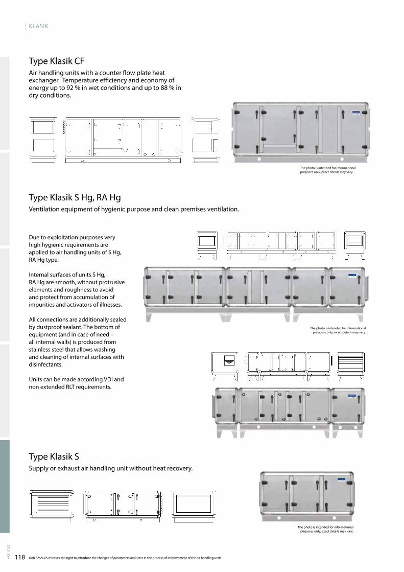
118
KLASIK
UAB AMALVA reserves the right to introduce the changes of parameters and sizes in the process of improvement of the air handling units.KK2-
17-0
2
The photo is intended for informational purposes only, exact details may vary.
Type Klasik S Hg, RA Hgventilation equipment of hygienic purpose and clean premises ventilation.
Due to exploitation purposes very high hygienic requirements are applied to air handling units of S Hg, RA Hg type.
Internal surfaces of units S Hg, RA Hg are smooth, without protrusive elements and roughness to avoid and protect from accumulation of impurities and activators of illnesses.
All connections are additionally sealed by dustproof sealant. The bottom of equipment (and in case of need – all internal walls) is produced from stainless steel that allows washing and cleaning of internal surfaces with disinfectants.
Units can be made according vDI and non extended RLT requirements.
The photo is intended for informational purposes only, exact details may vary.
Type Klasik CFAir handling units with a counter flow plate heat exchanger. Temperature efficiency and economy of energy up to 92 % in wet conditions and up to 88 % in dry conditions.
Type Klasik SSupply or exhaust air handling unit without heat recovery.
The photo is intended for informational purposes only, exact details may vary.

119All data can be calculated in KLASIK selection software. If data of performance do not correspond to data in selection software, please refer to data shown in software.
KLASIK DESIGN
KK2-
17-0
2
Filters
KLASIK units pocket synthetic or fiberglass filters with a class of a filtration from G4 up to F9 are used. Filters have big filtration surface what results in longer terms of exploitation. Filters are fastened by clamping mechanism which secures tightness and simplifies filter replacement procedure.
Air dampers
Closing air dampers installed in the air handling units are produced from aluminium, or galvanized steel blades with rubber sealing.
Casing
StandartAir handling units of KLASIK series characterize in reliable and stable design. Casing frameworks are made of aluminium pro-files and solid cast aluminium corner pieces.Covering panels are 50 mm thickness, made from double-skin galvanized or stainless sheet steel with 45 mm mineral wool sandwiched between sheet steel.Casing classification in conformance to standard EN 1886: leak-age L2; thermal transmittance T3; thermal bridging factor TB4.
Standart TBCasing frameworks are made of aluminium profiles and solid cast aluminium corner with thermal break system.
Covering panels are made from double-skin galvanized or stainless sheet. The panels are 60 mm thickness: 50 mm mineral wool are used for thermal and sound insulation and 10 mm of polyurethane foam.Casing classification in conformance to standard EN 1886: leak-age L2; thermal transmittance T2; thermal bridging factor TB3.
On request, casing can be painted. KLASIK gaskets and sealing are used to ensure perfect casing tightness and sound insula-tion. All doors are hinged and equipped with handles which can be locked.variable accessories such as adjustable feet, inspection win-dows, sections lighting, etc. are available on customers’ request.
Design
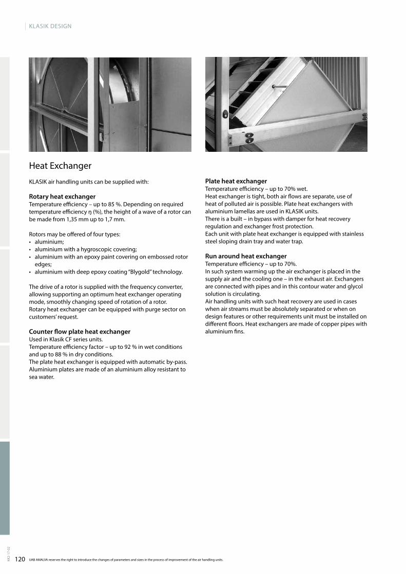
120 UAB AMALVA reserves the right to introduce the changes of parameters and sizes in the process of improvement of the air handling units.
KLASIK DESIGN
KK2-
17-0
2
Heat Exchanger
KLASIK air handling units can be supplied with:
Rotary heat exchanger Temperature efficiency – up to 85 %. Depending on required temperature efficiency ŋ (%), the height of a wave of a rotor can be made from 1,35 mm up to 1,7 mm.
Rotors may be offered of four types:• aluminium; • aluminium with a hygroscopic covering; • aluminium with an epoxy paint covering on embossed rotor
edges;• aluminium with deep epoxy coating “Blygold” techno logy.
The drive of a rotor is supplied with the frequency converter, allowing supporting an optimum heat exchanger operating mode, smoothly changing speed of rotation of a rotor. Rotary heat exchanger can be equipped with purge sector on customers’ request.
Counter flow plate heat exchanger Used in Klasik CF series units.Temperature efficiency factor – up to 92 % in wet conditions and up to 88 % in dry conditions.The plate heat exchanger is equipped with automatic by-pass. Aluminium plates are made of an aluminium alloy resistant to sea water.
Plate heat exchangerTemperature efficiency – up to 70% wet. Heat exchanger is tight, both air flows are separate, use of heat of polluted air is possible. Plate heat exchangers with aluminium lamellas are used in KLASIK units. There is a built – in bypass with damper for heat recovery regulation and exchanger frost protection.Each unit with plate heat exchanger is equipped with stainless steel sloping drain tray and water trap.
Run around heat exchangerTemperature efficiency – up to 70%.In such system warming up the air exchanger is placed in the supply air and the cooling one – in the exhaust air. Exchangers are connected with pipes and in this contour water and glycol solution is circulating. Air handling units with such heat recovery are used in cases when air streams must be absolutely separated or when on design features or other requirements unit must be installed on different floors. Heat exchangers are made of copper pipes with aluminium fins.
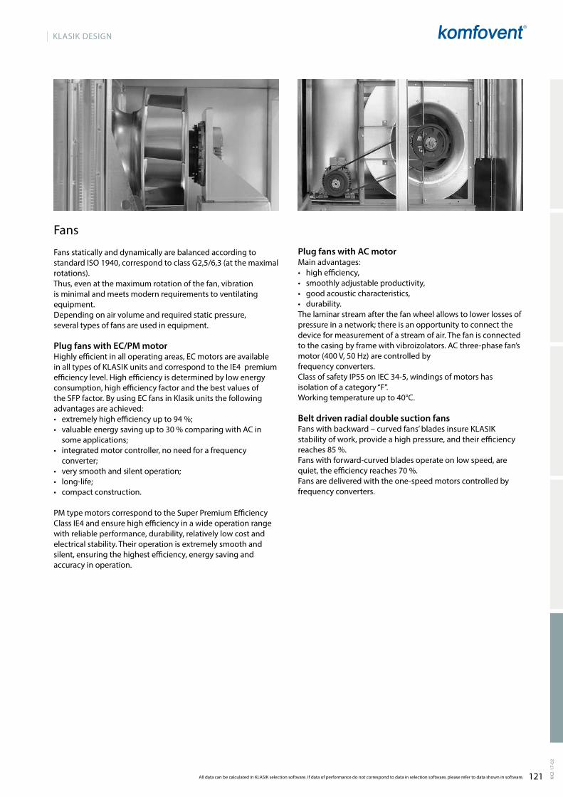
121All data can be calculated in KLASIK selection software. If data of performance do not correspond to data in selection software, please refer to data shown in software.
KLASIK DESIGN
KK2-
17-0
2
Fans
Fans statically and dynamically are balanced according to standard ISO 1940, correspond to class G2,5/6,3 (at the maximal rotations).Thus, even at the maximum rotation of the fan, vibration is minimal and meets modern requirements to ventilating equipment. Depending on air volume and required static pressure, several types of fans are used in equipment.
Plug fans with EC/PM motorHighly efficient in all operating areas, EC motors are avai lable in all types of KLASIK units and correspond to the IE4 premium efficiency level. High efficiency is determined by low energy consumption, high efficiency factor and the best values of the SFP factor. By using EC fans in Klasik units the following advantages are achieved:• extremely high efficiency up to 94 %;• valuable energy saving up to 30 % comparing with AC in
some applications;• integrated motor controller, no need for a frequency
converter;• very smooth and silent operation;• long-life;• compact construction.
Pm type motors correspond to the Super Premium Efficiency Class IE4 and ensure high efficiency in a wide operation range with reliable performance, durability, relatively low cost and electrical stability. Their operation is extremely smooth and silent, ensuring the highest efficiency, energy saving and accuracy in operation.
Plug fans with AC motormain advantages: • high efficiency, • smoothly adjustable productivity, • good acoustic characteristics,• durability. The laminar stream after the fan wheel allows to lower losses of pressure in a network; there is an opportunity to connect the device for measurement of a stream of air. The fan is connected to the casing by frame with vibroizolators. AC three-phase fan’s motor (400 v, 50 Hz) are controlled by frequency converters. Class of safety IP55 on IEC 34-5, windings of motors has isolation of a category “F”. Working temperature up to 40°C.
Belt driven radial double suction fansFans with backward – curved fans’ blades insure KLASIK stability of work, provide a high pressure, and their efficiency reaches 85 %.Fans with forward-curved blades operate on low speed, are quiet, the efficiency reaches 70 %.Fans are delivered with the one-speed motors controlled by frequency converters.
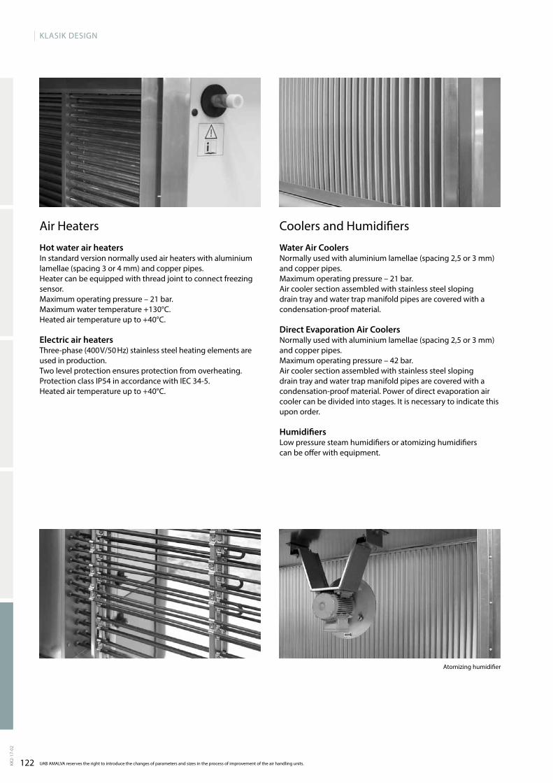
122 UAB AMALVA reserves the right to introduce the changes of parameters and sizes in the process of improvement of the air handling units.
KLASIK DESIGN
KK2-
17-0
2
Atomizing humidifier
Air Heaters
Hot water air heaters In standard version normally used air heaters with alumi nium lamellae (spacing 3 or 4 mm) and copper pipes. Heater can be equipped with thread joint to connect free zing sensor.maximum operating pressure – 21 bar.maximum water temperature +130°C. Heated air temperature up to +40°C.
Electric air heaters Three-phase (400 v/50 Hz) stainless steel heating elements are used in production.Two level protection ensures protection from overhea ting.Protection class IP54 in accordance with IEC 34-5.Heated air temperature up to +40°C.
Coolers and Humidifiers
Water Air CoolersNormally used with aluminium lamellae (spacing 2,5 or 3 mm) and copper pipes.maximum operating pressure – 21 bar.Air cooler section assembled with stainless steel sloping drain tray and water trap manifold pipes are covered with a condensation-proof material.
Direct Evaporation Air Coolers Normally used with aluminium lamellae (spacing 2,5 or 3 mm) and copper pipes.maximum operating pressure – 42 bar.Air cooler section assembled with stainless steel sloping drain tray and water trap manifold pipes are covered with a condensation-proof material. Power of direct evaporation air cooler can be divided into stages. It is necessary to indicate this upon order.
HumidifiersLow pressure steam humidifiers or atomizing humidifiers can be offer with equipment.

123All data can be calculated in KLASIK selection software. If data of performance do not correspond to data in selection software, please refer to data shown in software.
KLASIK DESIGN
KK2-
17-0
2
Sound attenuator section
Integrated sound attenuators or separated sound attenuators maybe offered with air handling units. High performance sound attenuators as well as ventilation unit ensures high sound attenuating level and are completely insulated casing. Inside the section, a wall sound attenuator is mounted. Its elements can be removed easi ly through the door without using tools. The elements should be removed one by one, not as a whole block, thus providing easy dry or semi-moist cleaning for the purpose of sanitation of the ventilation system. The elements of the sound attenuator are filled with acoustic silicate cotton used for an air channel. The silicate cotton is covered with a fibreglass mat preventing cotton particles from getting into an air channel when the airflow is running at high speed. The fibreglass mat is maximally resistant to the appearance of dust inside the air channel. Sound attenuators are avai lable with two types of cotton: silicate cotton and polyester cotton (Dacron) with a fibre mat and polypropylene fibre covering.
Additional accessories
KLASIK air handling units can be outdoor type. For such outdoor performance there is complete set enclo sed consisting of: • a protective roof,• intake and exhaust air hoods,• external grilles.
Also such additional elements are available:• inspection window,• sections lighting.

124
KLASIK
1 000 5 000 10 000 15 000 20 000 40 000 45 000 55 000 60 000 65 000 70 000 75 000 80 000 85 000 90 00050 00025 000 30 000 35 000
0.28 1.39 2.78 4.17 5.56 6.94 8.33 9.72 11.11 12.50 13.89 15.29 16.68 18.07 19.46 20.85 22.24 23.63 25.02
2
1
3
4
5
6
7
8
9
10
12
11
13
14
m3/h
m3/s
UAB AMALVA reserves the right to introduce the changes of parameters and sizes in the process of improvement of the air handling units.KK2-
17-0
2
For each air handling unit the individual automation control system can be offered. Automatics of air handling units can be mounted in separate control boxes or integrated inside unit. Depending on a degree of com p lexity of ventila ting system and required control func tions producer equips control system with controllers KOmFOvENT C5.
For the most perfect control and management of equipment KOmFOvENT engineers have developed a computer control system for one as well as the whole complex of units controlling. more specific information about a specific unit can be obtained using KLASIK air handling unit opera ting program.
Air flow
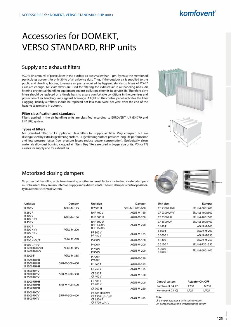
125
LB
H
ACCESSORIES for DOmEkt, VERSO StAnDARD, RHP units
kk2-
17-0
2
Accessories for Domekt, Verso stAnDArD, rHP units
motorized closing dampersto protect air handling units from freezing or other external factors motorized closing dampers must be used. they are mounted on supply and exhaust vents. there is dampers control possibility in automatic control system.
Control system Actuator ON/OFF
komfovent C4, C6 LF230 Lm230
komfovent C3, C5 LF24 Lm24
Note:LF damper actuator is with springreturn Lm damper actuator is without springreturn
Unit size Damper
r 200 V AGUJm125
r 250 Fr 300 Vr 400 H / Vr 450 V
AGUJm160
r 400 Fr 500 H / Vr 600 H / U
AGUJm200
r 500 Vr 700 H / V / F AGUJm250
r 900 U/H/Vr 1200 U/H/V/F r 1400 U/H/V
AGUJm315
r 2000 F AGUJm355
r 1600 UH/Hr 2000 UH/Hr 2500 UH/H
srUm300×400
r 1600 UV/Vr 2000 UV/Vr 2500 UV/V
srUm400×300
r 3000 UH/Hr 4000 UH/Hr 4500 UH/H
srUm400×500
r 3000 UV/Vr 4000 UV/Vr 4500 UV/V
srUm500×400
Unit size Damper
r 7000 H srUm1200×600
rHP 400 V AGUJm160
rHP 600 U AGUJm200
rHP 800 UrHP 1300 U rHP 1500 U
AGUJm250
PP 300 VPP 450 V AGUJm125
P 400 V AGUJm160
P 400 H AGUJm200
P 700 VP 900 V AGUJm200
P 700 HP 900 H AGUJm250
P 1600 F AGUJm315
CF 250 V AGUJm125
CF 250 FCF 400 V AGUJm160
CF 500 FCF 700 V AGUJm200
CF 700 H AGUJm250
CF 900 U/H/V/FCF 1300 U/H/V/FCF 1500 FCF 1700 U/H/V
AGUJm315
supply and exhaust filters99,9 % (in amount) of particulates in the outdoor air are smaller than 1 µm. By mass the mentioned particulates account for only 30 % of all airborne dust. thus, if the outdoor air is supplied to the public and dwelling houses, to ensure air purity required by hygienic standards, filters of m5F7 class are enough. m5 class filters are used for filtering the exhaust air in air handling units. Air filtering protects air handling equipment against pollution, extends its service life. therefore dirty filters should be replaced on a timely basis to assure comfortable conditions in the premises and protection of air handling units against breaka ge. A light on the control panel indicates the filter clogging. Usually air filters should be replaced not less than twice per year: after the end of the heating season and in autumn.
Filter classification and standardsFilters applied in the air handling units are classified according to eUroVent 4/9 (en 779 and en 1882) system.
Types of filtersm5 (standard filter) or F7 (optional) class filters for supply air filter. Very compact, but are distinguished by extra large filte ring surface. Large filtering surface provides longlife performance and low pressure losses (low pressure losses reduce power consumption). ecologically clean materials allow just bur ning clogged air filters. Bag filters are used in bigger size units: m5 (or F7) classes for supply and for exhaust air.
Unit size Damper
CF 2300 UH/H srUm300×400
CF 2300 UV/V srUm400×300
CF 3500 UH srUm400×500
CF 3500 UV srUm500×400
s 650 F AGUJm160
s 800 F AGUJm200
s 1000 F AGUJm250
s 1300 F AGUJm250
s 2100 F srUm750×250
s 3000 Fs 4000 F srUm600×400
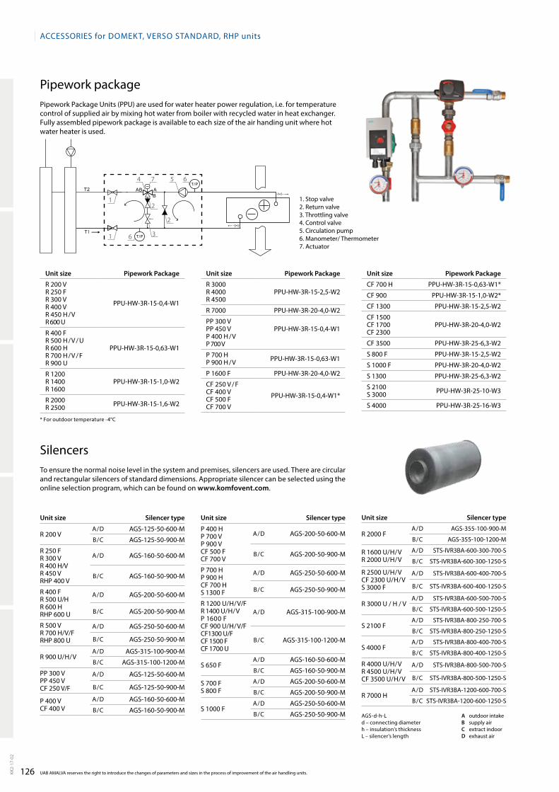
126
4 5 6
6
7
1
1
2
3
2
ACCESSORIES for DOmEkt, VERSO StAnDARD, RHP units
UAB AmALVA reserves the right to introduce the changes of parameters and sizes in the process of improvement of the air handling units.kk2-
17-0
2
Pipework packagePipework Package Units (PPU) are used for water heater power regulation, i.e. for temperature control of supplied air by mixing hot water from boiler with recycled water in heat exchanger. Fully assembled pipework package is available to each size of the air handing unit where hot water heater is used.
1. stop valve2. return valve3. throttling valve4. Control valve5. Circulation pump6. manometer/ thermometer7. Actuator
Unit size Pipework Package
r 200 Vr 250 Fr 300 Vr 400 Vr 450 H / Vr 600 U
PPUHW3r150,4W1
r 400 Fr 500 H / V / Ur 600 Hr 700 H / V / Fr 900 U
PPUHW3r150,63W1
r 1200 r 1400r 1600
PPUHW3r151,0W2
r 2000r 2500 PPUHW3r151,6W2
Unit size Pipework Package
r 3000r 4000r 4500
PPUHW3r152,5W2
r 7000 PPUHW3r204,0W2
PP 300 VPP 450 VP 400 H / VP 700 V
PPUHW3r150,4W1
P 700 HP 900 H / V PPUHW3r150,63W1
P 1600 F PPUHW3r204,0W2
CF 250 V / FCF 400 VCF 500 FCF 700 V
PPUHW3r150,4W1*
Unit size Pipework Package
CF 700 H PPUHW3r150,63W1*
CF 900 PPUHW3r151,0W2*
CF 1300 PPUHW3r152,5W2
CF 1500CF 1700CF 2300
PPUHW3r204,0W2
CF 3500 PPUHW3r256,3W2
s 800 F PPUHW3r152,5W2
s 1000 F PPUHW3r204,0W2
s 1300 PPUHW3r256,3W2
s 2100s 3000 PPUHW3r2510W3
s 4000 PPUHW3r2516W3
silencersto ensure the normal noise level in the system and pre mises, silencers are used. there are circular and rectangular silencers of standard dimensions. Appropriate silencer can be selected using the online selection program, which can be found on www.komfovent.com.
Unit size Silencer type
r 200 VA/D AGs12550600m
B/C AGs12550900m
r 250 Fr 300 Vr 400 H/Vr 450 V rHP 400 V
A/D AGs16050600m
B/C AGs16050900m
r 400 Fr 500 U/Hr 600 HrHP 600 U
A/D AGs20050600m
B/C AGs20050900m
r 500 Vr 700 H/V/FrHP 800 U
A/D AGs25050600m
B/C AGs25050900m
r 900 U/H/VA/D AGs315100900m
B/C AGs3151001200m
PP 300 VPP 450 VCF 250 V/F
A/D AGs12550600m
B/C AGs12550900m
P 400 VCF 400 V
A/D AGs16050600m
B/C AGs16050900mAGsdhLd – connecting diameterh – insulation’s thicknessL – silencer’s length
A outdoor intakeB supply airC extract indoorD exhaust air
Unit size Silencer type
P 400 HP 700 V P 900 VCF 500 FCF 700 V
A/D AGs20050600m
B/C AGs20050900m
P 700 HP 900 HCF 700 Hs 1300 F
A/D AGs25050600m
B/C AGs25050900m
r 1200 U/H/V/Fr 1400 U/H/VP 1600 FCF 900 U/H/V/FCF1300 U/FCF 1500 FCF 1700 U
A/D AGs315100900m
B/C AGs3151001200m
s 650 FA/D AGs16050600m
B/C AGs16050900m
s 700 Fs 800 F
A/D AGs20050600m
B/C AGs20050900m
s 1000 FA/D AGs25050600m
B/C AGs25050900m
Unit size Silencer type
r 2000 FA/D AGs355100900m
B/C AGs3551001200m
r 1600 U/H/Vr 2000 U/H/V
A/D stsIVr3BA600300700s
B/C stsIVr3BA6003001250s
r 2500 U/H/VCF 2300 U/H/Vs 3000 F
A/D stsIVr3BA600400700s
B/C stsIVr3BA6004001250s
r 3000 U / H / VA/D stsIVr3BA600500700s
B/C stsIVr3BA6005001250s
s 2100 FA/D stsIVr3BA800250700s
B/C stsIVr3BA8002501250s
s 4000 FA/D stsIVr3BA800400700s
B/C stsIVr3BA8004001250s
r 4000 U/H/Vr 4500 U/H/VCF 3500 U/H/V
A/D stsIVr3BA800500700s
B/C stsIVr3BA8005001250s
r 7000 HA/D stsIVr3BA1200600700s
B/C stsIVr3BA12006001250s
* For outdoor temperature 4°C

127
B ×
H
B1 ×
H1
L
ACCESSORIES for DOmEkt, VERSO StAnDARD, RHP units
kk2-
17-0
2
Water and direct evaporation air coolersAir cooler is mounted on the outside of the unit.Casing of the cooler section corresponds to the unit’s ca sing: galvanized steel sheets with internal mineral wool insulation of 45 mm thickness. Cooler section is assembled with a drop separator and a drain tray. Cooler control function is provided in the automatic control system of the unit.Internal fluid – r410A, water 7/12.Air temperature in/out – 30 / 18 °C.
* with drop eliminator.
Unit size Supply air volume, m³/h Cooler’s type Capacity,
kW
Air pressure drop*, Pa
Fluid pressure loss, kPa
B×H×L, mm
B1×H1, mm
Tubes connections,
“ / mm
Weight, kg
r 400P 400CF 400PP 450
400DCF0,43 2,7 16 0,3 600×550×390 300×400 ½ / 22 40
DCW0,43 2,7 34 15,8 505×550×390 300×400 ½ 33
r 450r 500CF 500
500DCF0,53 3,4 19 0,4 600×550×390 400×300 ½ / 22 40
DCW0,53 3,4 30 29,5 600×550×390 400×300 ½ 35
r 600s 650 650
DCF0,75 5,3 53 3,9 705×610×390 500×400 ½ / 22 46
DCW0,75 4,4 27 9,9 705×610×390 500×400 ½ 42
r 700P 700CF 700
700DCF0,75 4,7 22 0,4 705×610×390 500×400 ½ / 22 49
DCW0,75 4,7 29 11,2 705×610×390 500×400 ½ 42
s 800s 1000 800
DCF0,96 6,1 29 0,7 705×610×390 500×400 ½ / 22 49
DCW0,96 6,0 36 3,7 705×610×390 500×400 ¾ 45
r 900P 900CF 900
900DCF0,96 6,1 29 0,7 705×610×390 500×400 ½ / 22 49
DCW0,96 6,0 36 3,7 705×610×390 500×400 ¾ 45
r 1200 1200DCF1,28 8,2 41 1,2
705×610×390 500×400½ / 22 49
DCW1,28 8,1 60 6,3 ¾ 45
CF 1300s 1300r 1400
1400DCF1,410 9,5 69 8,5
705×610×390 500×400½ / 22 51
DCW1,49 9,4 78 8,3 ¾ 45
CF 1500r 1600P 1600CF 1700
1600DCF1,611 10,8 73 11,8
755×610×420 500×400½ / 22 56
DCW1,611 10,7 83 11,2 ¾ 46
r 2000 s 2100 2000
DCF2,014 13,7 67 22,6920×610×420 700×400
5�8 / 22 65
DCW2,013 13,4 78 20,6 ¾ 57
r 2500CF 2300 2500
DCF2,517 17,1 65 11,71080×670×420 800x400
5�8 / 22 79
DCW2,517 16,9 55 28,3 1 65
r 3000s 3000 3000
DCF3,020 20,4 90 16,51080×670×420 800x400
5�8 / 22 79
DCW3,020 20,2 102 11 1 69
CF 3500r 4000 s 4000
4000DCF4,027 27,2 92 35,8
1220×730×420 900×5005�8 / 22 97
DCW4,027 27 106 17,1 1 82
r 4500 4500DCF4,531 30,6 93 28,4
1220×790×420 900×600¾ / 22 103
DCW4,530 30,3 108 31,8 1 87
r 7000 7000DCF7,048 2×23,8 99 8,2 1500×790×480
1200×6002×¾ / 2×22 125
DCW7,047 46,5 138 23,4 1500×790×420 1 ½ 105
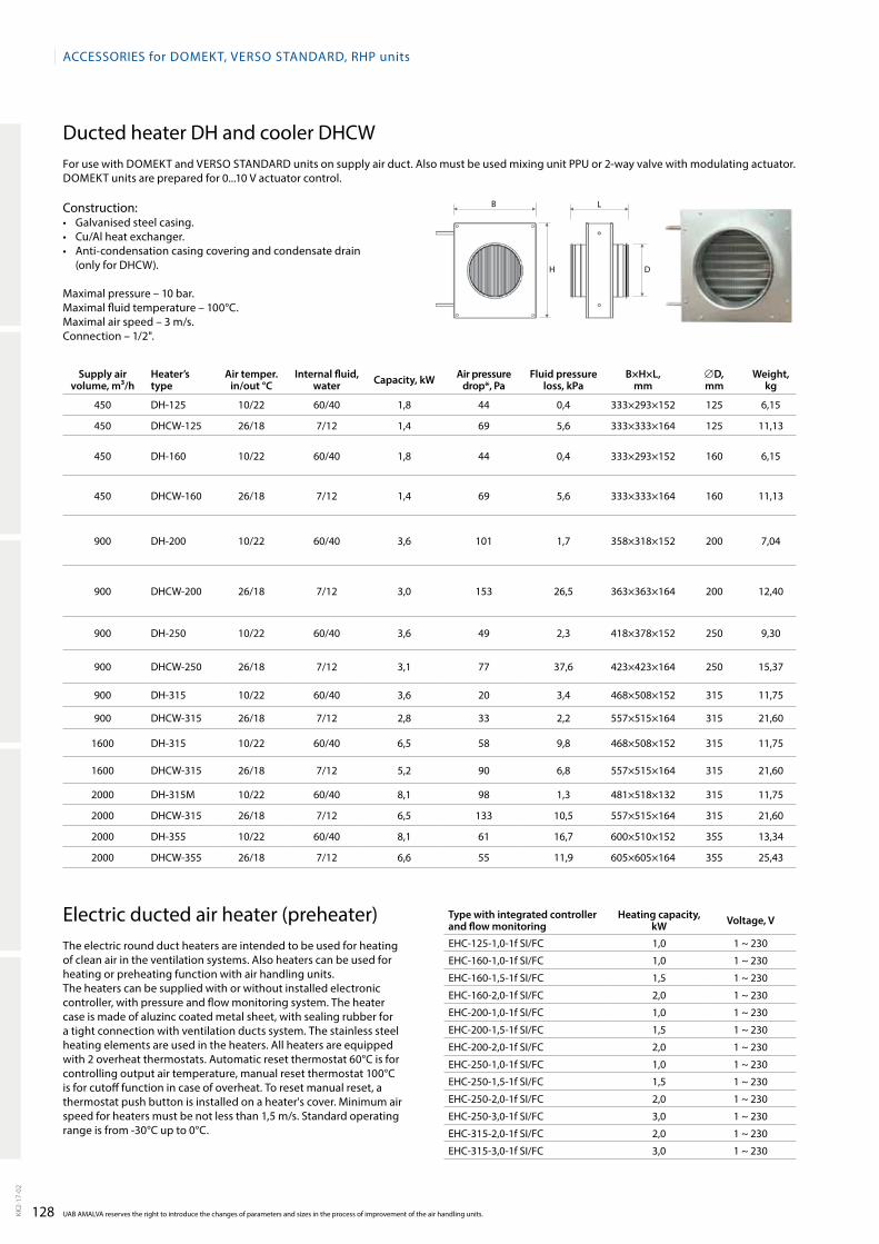
128
B
H D
L
ACCESSORIES for DOmEkt, VERSO StAnDARD, RHP units
UAB AmALVA reserves the right to introduce the changes of parameters and sizes in the process of improvement of the air handling units.kk2-
17-0
2
Supply air volume, m³/h
Heater’s type
Air temper. in/out °C
Internal fluid,water Capacity, kW Air pressure
drop*, PaFluid pressure
loss, kPaB×H×L,
mm∅D, mm
Weight, kg
450 DH125 10/22 60/40 1,8 44 0,4 333×293×152 125 6,15
450 DHCW125 26/18 7/12 1,4 69 5,6 333×333×164 125 11,13
450 DH160 10/22 60/40 1,8 44 0,4 333×293×152 160 6,15
450 DHCW160 26/18 7/12 1,4 69 5,6 333×333×164 160 11,13
900 DH200 10/22 60/40 3,6 101 1,7 358×318×152 200 7,04
900 DHCW200 26/18 7/12 3,0 153 26,5 363×363×164 200 12,40
900 DH250 10/22 60/40 3,6 49 2,3 418×378×152 250 9,30
900 DHCW250 26/18 7/12 3,1 77 37,6 423×423×164 250 15,37
900 DH315 10/22 60/40 3,6 20 3,4 468×508×152 315 11,75
900 DHCW315 26/18 7/12 2,8 33 2,2 557×515×164 315 21,60
1600 DH315 10/22 60/40 6,5 58 9,8 468×508×152 315 11,75
1600 DHCW315 26/18 7/12 5,2 90 6,8 557×515×164 315 21,60
2000 DH315m 10/22 60/40 8,1 98 1,3 481×518×132 315 11,75
2000 DHCW315 26/18 7/12 6,5 133 10,5 557×515×164 315 21,60
2000 DH355 10/22 60/40 8,1 61 16,7 600×510×152 355 13,34
2000 DHCW355 26/18 7/12 6,6 55 11,9 605×605×164 355 25,43
Ducted heater DH and cooler DHCWFor use with Domekt and Verso stAnDArD units on supply air duct. Also must be used mixing unit PPU or 2way valve with modulating actuator. Domekt units are prepared for 0...10 V actuator control.
Construction:• Galvanisedsteelcasing.• Cu/Alheatexchanger.• Anti-condensationcasingcoveringandcondensatedrain
(only for DHCW).
maximal pressure – 10 bar.maximal fluid temperature – 100°C.maximal air speed – 3 m/s.Connection – 1/2".
electric ducted air heater (preheater) the electric round duct heaters are intended to be used for heating of clean air in the ventilation systems. Also heaters can be used for heating or preheating function with air handling units.the heaters can be supplied with or without installed electronic controller, with pressure and flow monitoring system. the heater case is made of aluzinc coated metal sheet, with sealing rubber for a tight connection with ventilation ducts system. the stainless steel heating elements are used in the heaters. All heaters are equipped with 2 overheat thermostats. Automatic reset thermostat 60°C is for controlling output air temperature, manual reset thermostat 100°C is for cutoff function in case of overheat. to reset manual reset, a thermostat push button is installed on a heater's cover. minimum air speed for heaters must be not less than 1,5 m/s. standard operating range is from 30°C up to 0°C.
Type with integrated controller and flow monitoring
Heating capacity, kW Voltage, V
eHC1251,01f sI/FC 1,0 1 ~ 230
eHC1601,01f sI/FC 1,0 1 ~ 230
eHC1601,51f sI/FC 1,5 1 ~ 230
eHC1602,01f sI/FC 2,0 1 ~ 230
eHC2001,01f sI/FC 1,0 1 ~ 230
eHC2001,51f sI/FC 1,5 1 ~ 230
eHC2002,01f sI/FC 2,0 1 ~ 230
eHC2501,01f sI/FC 1,0 1 ~ 230
eHC2501,51f sI/FC 1,5 1 ~ 230
eHC2502,01f sI/FC 2,0 1 ~ 230
eHC2503,01f sI/FC 3,0 1 ~ 230
eHC3152,01f sI/FC 2,0 1 ~ 230
eHC3153,01f sI/FC 3,0 1 ~ 230
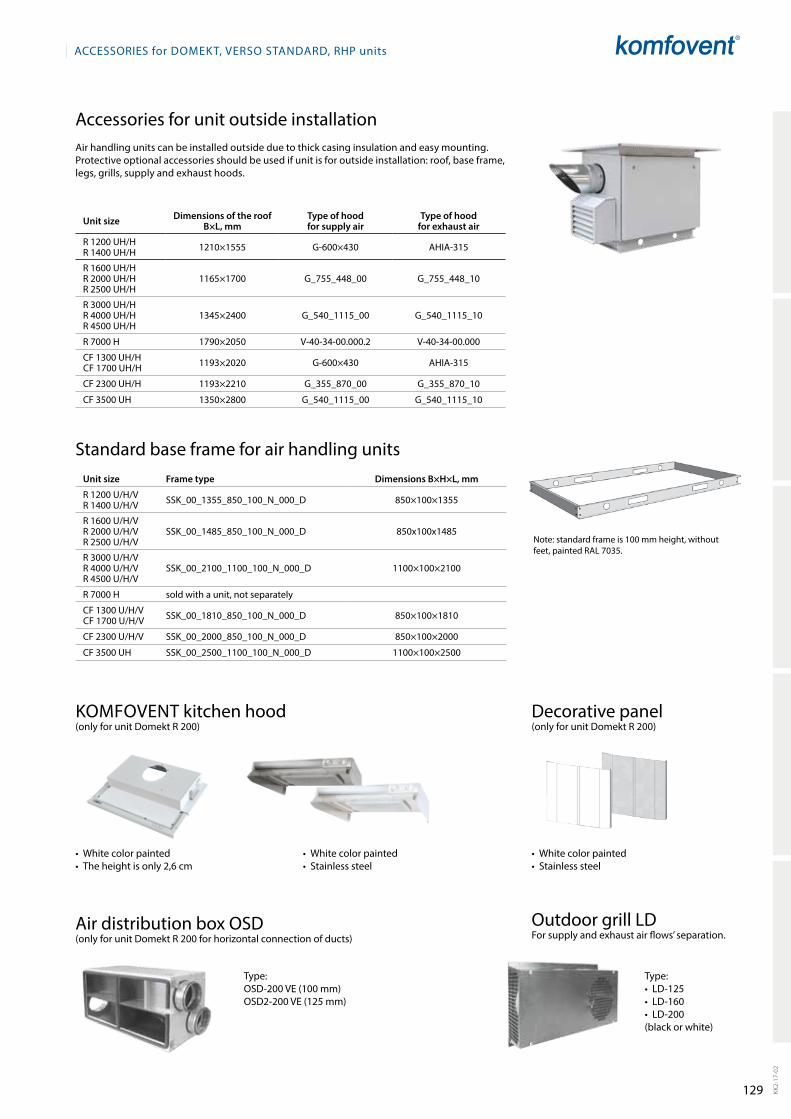
129
ACCESSORIES for DOmEkt, VERSO StAnDARD, RHP units
kk2-
17-0
2
Unit size Dimensions of the roof B×L, mm
Type of hood for supply air
Type of hood for exhaust air
r 1200 UH/Hr 1400 UH/H 1210×1555 G600×430 AHIA315
r 1600 UH/Hr 2000 UH/Hr 2500 UH/H
1165×1700 G_755_448_00 G_755_448_10
r 3000 UH/H r 4000 UH/H r 4500 UH/H
1345×2400 G_540_1115_00 G_540_1115_10
r 7000 H 1790×2050 V403400.000.2 V403400.000
CF 1300 UH/HCF 1700 UH/H 1193×2020 G600×430 AHIA315
CF 2300 UH/H 1193×2210 G_355_870_00 G_355_870_10
CF 3500 UH 1350×2800 G_540_1115_00 G_540_1115_10
Accessories for unit outside installationAir handling units can be installed outside due to thick casing insulation and easy mounting. Protective optional accessories should be used if unit is for outside installation: roof, base frame, legs, grills, supply and exhaust hoods.
standard base frame for air handling units
note: standard frame is 100 mm height, without feet, painted rAL 7035.
Unit size Frame type Dimensions B×H×L, mm
r 1200 U/H/Vr 1400 U/H/V ssk_00_1355_850_100_n_000_D 850×100×1355
r 1600 U/H/V r 2000 U/H/Vr 2500 U/H/V
ssk_00_1485_850_100_n_000_D 850x100x1485
r 3000 U/H/V r 4000 U/H/V r 4500 U/H/V
ssk_00_2100_1100_100_n_000_D 1100×100×2100
r 7000 H sold with a unit, not separately
CF 1300 U/H/VCF 1700 U/H/V ssk_00_1810_850_100_n_000_D 850×100×1810
CF 2300 U/H/V ssk_00_2000_850_100_n_000_D 850×100×2000
CF 3500 UH ssk_00_2500_1100_100_n_000_D 1100×100×2500
Air distribution box osD(only for unit Domekt r 200 for horizontal connection of ducts)
outdoor grill LDFor supply and exhaust air flows’ separation.
komFoVent kitchen hood(only for unit Domekt r 200)
Decorative panel(only for unit Domekt r 200)
type:•LD-125•LD-160•LD-200(black or white)
•Whitecolorpainted•Stainlesssteel
•Whitecolorpainted•Stainlesssteel
type:osD200 Ve (100 mm)osD2200 Ve (125 mm)
•Whitecolorpainted•Theheightisonly2,6cm
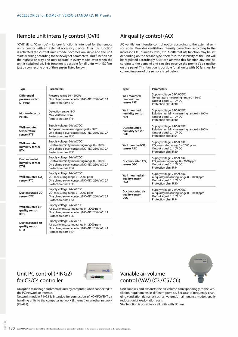
130
ACCESSORIES for DOmEkt, VERSO StAnDARD, RHP units
UAB AmALVA reserves the right to introduce the changes of parameters and sizes in the process of improvement of the air handling units.kk2-
17-0
2
Type Parameters
Differential pressure switch DTV500
Pressure range 50 – 500Paone changeover contact (no+nC) 250V AC, 1AProtection class IP54
Motion detector PIR180
Detection angle 180ºmax. distance 12 mProtection class IP44
Wall mounted temperature sensor RTT
supply voltage: 24V AC/DCtemperature measuring range 0 – 50ºCone changeover contact (no+nC) 250V AC, 2AProtection class IP30
Wall mounted humidity sensor RTH
supply voltage: 24V AC/DCrelative humidity measuring range 0 – 100%one changeover contact (no+nC) 250V AC, 2AProtection class IP30
Duct mounted humidity sensor DTH
supply voltage: 24V AC/DCrelative humidity measuring range 0 – 100%one changeover contact (no+nC) 250V AC, 2AProtection class IP54
Wall mounted CO2 sensor RTC
supply voltage: 24V AC/DCCo2 measuring range 0 – 2000 ppmone changeover contact (no+nC) 250V AC, 2AProtection class IP30
Duct mounted CO2 sensor DTC
supply voltage: 24V AC/DCCo2 measuring range 0 – 2000 ppmone changeover contact (no+nC) 250V AC, 2AProtection class IP54
Wall mounted air quality sensor RTQ
supply voltage: 24V AC/DCAir quality measuring range 0 – 2000 ppmone changeover contact (no+nC) 250V AC, 2AProtection class IP30
Duct mounted air quality sensor DTQ
supply voltage: 24V AC/DCAir quality measuring range 0 – 2000 ppmone changeover contact (no+nC) 250V AC, 2AProtection class IP54
remote unit intensity control (oVr)“oVr” (eng. “override” – ignore) function is intended for the remote unit’s control with an external accessory device. After this function is activated the current unit’s mode becomes omissible and the unit starts working according to the newly set parameters. this function has the highest priority and may operate in every mode, even when the unit is switched off. this function is possible for all units with eC fans just by connecting one of the sensors listed below.
Air quality control (AQ)AQ ventilation intensity control option according to the external sensor signal. Provides ventilation intensity correction, according to the increased Co2, humidity level, etc. A different AQ function may be set depending on the sensor type, therefore, the intensity of the unit will be regulated accordingly. User can activate this function anytime according to the demand and can also observe the premise’s air quality on the panel. this function is possible for all units with eC fans just by connecting one of the sensors listed below.
Type Parameters
Wall mounted temperature sensor RST
supply voltage: 24V AC/DCtemperature measuring range 0 – 50ºCoutput signal 0...10V DCProtection class IP30
Wall mounted humidity sensor RSH
supply voltage: 24V AC/DCrelative humidity measuring range 0 – 100%output signal 0...10V DCProtection class IP30
Duct mounted humidity sensor DSH
supply voltage: 24V AC/DCrelative humidity measuring range 0 – 100%output signal 0...10V DCProtection class IP54
Wall mounted CO2 sensor RSC
supply voltage: 24V AC/DCCo2 measuring range 0 – 2000 ppmoutput signal 0...10V DCProtection class IP30
Duct mounted CO2 sensor DSC
supply voltage: 24V AC/DCCo2 measuring range 0 – 2000 ppmoutput signal 0...10V DCProtection class IP54
Wall mounted air quality sensorRSQ
supply voltage: 24V AC/DCAir quality measuring range 0 – 2000 ppmoutput signal 0...10V DCProtection class IP30
Duct mounted air quality sensor DSQ
supply voltage: 24V AC/DCAir quality measuring range 0 – 2000 ppmoutput signal 0...10V DCProtection class IP54
Variable air volume control (VAV) (C3 / C5 / C6)Unit supplies and exhausts the air volume correspondingly to the ventilation requirements in different premise. Because of frequently changing ventilation demands such air volume’s maintenance mode signally reduces unit’s exploitation costs. VAV function is possible for all units with eC fans.
Unit PC control (PInG2) for C3/C4 controllerAn option to manage and control units by computer, when connected to the PC network or Internet.network module PInG2 is intended for connection of komFoVent air handling units to the computer network (ethernet) or another network (rs485).

131
ACCESSORIES for DOmEkt, VERSO StAnDARD, RHP units
kk2-
17-0
2
electric wiring of air handling unitsWhen the air handling unit is installed, the user should just connect it to the mains power supply and install one temperature sensor in the supply air duct, and in case of need extend the connecting cable of the control panel. the units with a hot water air heater are provided with extra connecting cables for a heating damper drive, a pump, and an air damper drive. If the air handling unit voltage is ~230 V; 50 Hz it is necessary to install the socket with grounding of corresponding capacity. If the voltage is ~400 V; 50 Hz, the cable of electrical power supply is connected to the main switch, which is located on the unit’s outside wall.the air handling units power supply cable types are specified in the table.
Unit size Power supply cable
r 200r 250r 300r 400r 450r 500r 600r 700r 900 W
3×1,5 mm2
r 900 er 1200 er 1400 er 1600 e
5×1,5 mm2
r 2000 er 2500 er 3000 e
5×2,5 mm2
r 4000 er 4500 e 5×6 mm2
r 1200 Wr 1400 Wr 1600 Wr 2000 Wr 2500 W
3×1,5 mm2
r 3000 Wr 4000 Wr 4500 Wr 7000 W
5×1,5 mm2
rHP 400rHP 600 3×1,5 mm2
Control panel Connection cabel for control panel (10 m)
C6.1, C6.2, C5.1, C4.1, C3.1 4×0,22 mm2
Unit size Power supply cable
rHP 800rHP 1300rHP 1500
5×1,5 mm2
PP 300P 400PP 450P 700P 900 WP 1600 WP 2000 W
3×1,5 mm2
P 1600 eP 2000 e 5×2,5 mm2
P 900 e 5×1,5 mm2
CF 250CF 400CF 500CF 700CF 900 W
3×1,5 mm2
CF 900 eCF 1300 eCF 1500 eCF 1700 e
5×1,5 mm2
CF 2300 e 5×2,5 mm2
CF 1300 WCF 1500 WCF 1700 WCF 2300 W
3×1,5 mm2
CF 3500 W 5×1,5 mm2
Unit size Power supply cable
s 650 e/3s 800 e/3 3×2,5 mm2
s 650 e/6s 700 e/6s 800 e/6s 1000 e/6s 1300 e/6
5×1,5 mm2
s 700 e/9s 800 e/9s 1000 e/9s 1300 e/9
5×2,5 mm2
s 1000 e/15s 1300 e/15s 2100 e/15
5×4 mm2
s 2100 e/22,5 5×10 mm2
s 800 Ws 1000 Ws 1300 Ws 2100 W
3×1,5 mm2
s 3000 Ws 4000 W 5×1,5 mm2

132
L1 L2
L1
L1
r1 r2
r1
r1
H V F F
UAB AMALVA reserves the right to introduce the changes of parameters and sizes in the process of improvement of the air handling units.KK2-
17-0
2
DOMEKT-R-200-L-V-EC/0.137-F7-M5-HE/1-X-L1-C4.1-O/By
Characteristic of heat exchanger
Rotary – wave height L – 1,7 mmXL – 1,5 mmUL – 1,35 mm/AZ – sorption zeoliteAe – aluminium epoxy coatedAZm – hygroscopic
Plate 1,8; 2,2; 2,5; 3; 4; 5; 6 – distance between plates
Counter flow 1.6, 2, 2.5, 3 ... – distance between plates
Run aroundxyz / xyz
Heat exchanger with heat pump20/17 kW cooling/heating power
MotorAC / Ie4 (efficiency)eC / p/p (supply/exhaust motor power)Pm / p (power)
SeriesDomektVersokLAsIk
Unit size 20090012007000, 10901–14
Аir filter classG4m5m6F7F8F9
Inspection sider1r2L1L2
Additional equipment/characteristicsa – silencerHu – humidifierrAL 9001– colorBy – external bypassHg – hygienic versionout – outdoor versionCol – partial coloring
ControlC3.1C4.1C5.1C6.1C6.2
Supply Еxhaust
Type of heat exchangerr – rotary P – platePP – double platerA – run aroundCF – counter flowrHP – rotary with heat pumpPHP – plate with heat pumpm – recirculation sections – supply unit
Duct connectionH – horizontal V – vertical U – universalF – ceiling HV – horizontal and vertical
Heater/characteristicHW – water /xyHe – electric / pHDX – direct expansion / xyzHs – steam / xyHG – gas / pHCW – reversible W / xyHCDX – reversible DX / xyzHW/DH – duct mounted water
Cooler/characteristicCW – water / xyCDX – direct expansion / xyz
x – number of rowsy – distance between the platesp – powerz – number of circuits
Unit marking and ordering sample
Inspection side:
supply air
Inspection side is determined by the supply air direction, looking at the unit from the user‘s side.
UnIt mArkInG

UAB AmAlvAOzo str. 10, lT-08200 [email protected] 2017-02