ventilation critera for idms facility/67531/metadc675982/m2/1/high_res_d/392769.pdfidms is designed...
TRANSCRIPT

WSRC-RP-96-0282
Ventilation Critera for IDMS Facility
by D. P. Lambert Westinghouse Savannah River Company Savannah River Site Aiken, South Carotina 29808
DISCLAIMER
This report was prepared as an account of work sponsored by an agency of the United States Government. Neither the United States Government nor any agency thereof, nor any of their employees, makes any warranty, express or implied, or assumes any legal liability or responsi- bility for the accuracy, completeness, or usefulness of any information, apparatus, product, or process disclosed, or represents that its use would not infringe privately owned rights. Refer- ence herein to any specific commercial product, process, or service by trade name, trademark, manufacturer, or otherwise does not necessarily constitute or imply its endorsement, recom- mendation, or favoring by the United States Government or any agency thereof. The views and opinions of authors expressed herein do not necessarily state or reflect those of the United States Government or any agency thereof.
___- __I____
DOE Contract No. DE-AC09-89SR18035
This paper was prepared in connection with work done under the above contract number with the U. S. Department of Energy. By acceptance of this paper, the publisher and/or recipient acknowledges the U. S. Government's right to retain a nonexclusive, royalty-free license in and to any copyright covering this paper, along with the right to reproduce and to authorize others to reproduce alt or part of the copyrighted paper.
DISCLAIMER
Portions of this document may be illegible in electronic image products. Images are produced from the best available original document.

DISCLAIMER
This report was prepared as an account of work sponsored by an agency of the United States Government. Neither the United States Government nor any agency thereof, nor any of their employees, makes any warranty, express or implied, or assumes any legal liability or responsibility for the accuracy, completeness, or usefulness of any information, apparatus, product, or process disclosed, or represents that its use would not infiinge privately owned rights. Reference herein to any specific commercial product, process, or service by trade name, trademark, manufacturer, or otherwise does not necessarily constitute or imply its endorsement, recommendation, or favoring by the United States Government or any agency thereof. The views and opinions of authors expressed herein do not necessarily state or reflect those of the United States Government or any agency thereof.
This report has been reproduced directly from the best available copy.
Available to DOE and DOE contractors from the Office of Scientific and Technical Information, P.O. Box 62, Oak Ridge, TN 37831; prices available from (615) 576-8401.
Available to the public from the National Technical Infomation Service, U.S. Department of Commerce,- 5285 Port Royal Road, Springfield, VA 22161.

WESTINGHOUSE SAVANNAH RIVER COMPANY SAVANNAH RIVER TECHNOLOGY CENTER
WSRC-R P-96-0282-TL
CC: E. W. Holtzscheiter, 773-A L. K. Thebo, 730-48
G. F. Hayford, 704-T R. E. Roaden, 704-T M. F. Williams, 704-1T B. J. Hardy, 704-1T SRTC-PD-File
D. L. Booth, 704-T
Keywords: IDMS, PHR, Containment, Mercury, Benzene, Facility Evaluation Board.
Retention Period: Permanent
July 3, 1996
To: L. F. Landon, 704-IT
From: D. P. Lambert, 7 0 4 - 1 T a a VENTILATION CRITERIA FOR IDMS FACILITY (U)
The attached report specifies the ventilation necessary for the safe operation of the IDMS facility. The report has been approved by the managers of DWPT, Industrial Hygiene and TNX Operations. This report will close-out the Facility Evaluation Board findings concerning IDMS ventilation [1,2]. The new Process Hazards Review report will incorporate all of the recommendations of this report.
The ventilation criteria was written to justify the ventilation needed for safe operation and the steps needed to ensure the ventilation is operable. The ventilation criteria eliminates the requirement for benzene and mercury monitoring of IDMS which is consistent with IDMS practice for the last seven years. However, IDMS practice was in opposition to the benzene and mercury monitoring required by the initial IDMS Process Hazards Review [3].
Any questions concerning this report should be directed to D. P. Lambert, 7-7680.

WSRC-RP-96-0282 Keywords: IDMS, PHR, Containment,
Mercury, Benzene, Facility Evaluation Board.
Retention Period: 15 years after project completion
VENTILATION CRITERIA FOR IDMS FACILITY (U)
D. P. LAMBERT
Publication Date: July 3, 1996
C. T. Randall, 704-T Authorized Derivative Classifier
River Company Westinghouse Savannah Savannah River Site Aiken, SC 29808
ShVAhNNhf.1 Hi V E K SI1'B

WESTINGHOUSE SAVANNAH RIVER COMPANY WSRC-RP-96-0282 SAVANNAH RIVER TECHNOLOGY CENTER
Introduction
Both Facility Evaluation Board (FEB) reviews of the Integrated DWPF Melter System (IDMS) have identified the inconsistency of the current IDMS Process Hazards Review (PHR) versus actual IDMS practice as regards the criteria to contain air borne pollutants that may be present in the Process Room (e.g. benzene and mercury) [1,2]. The PHR states that a 1.0 in wc pressure differential be maintained between the IDMS Process Room and Building 672-T. In addition, the PHR further_specifies that the linear velocity through openings into the Process Room (e.g. open doors) be equal to or greater than 150 fpm. Finally, the PHR recommended that mercury vapor and benzene monitors be installed in the Process Room ventilation exhaust to alert personnel to the presence of vapors of benzene and/or mercury before entering the Process Room [3].
This report summarizes the results of a reassessment of these criteria and the specific recommendation for permanent installation of mercury and benzene vapor monitors in the vapor exhaust of the Process Room.
S u mmarv
The current PHR specification of a 1 in wc differential pressure requirement and the 150 linear feet per minute air flow criteria are judged to be excessively restrictive for IDMS in view of recent ventilation performance tests [4] and a reassessment of the facility administrative controls and safety system interlocks that are already in place. Further, based on the credible scenarios that could result in the release of benzene and mercury vapors into the Process, permanently installed benzene and mercury vapor monitors in the vapor exhaust from the Process Room would contribute little if any additional personnel protection.
Recommendat ions
The IDMS Facility is currently being de-inventoried of all product slurries generated during previous process simulations as well as all accumulated waste streams (e.g. condensates, sump contents, etc.) and placed in “cold standby”. If the decision is made to resume process simulations in the IDMS Facility, it is recommended that the following criteridrecommendations be adopted and incorporated into the PHR that is currently being updated:
‘ The pressure differential between the Process Room and Building 672-T be maintained at a minimum of 0.15 in wc as measured with all doors closed.
The Process Room air flow requirement is 2 9000 cfm.
On a monthly frequency, perform smoke tests to confirm that the air flow is from Building 672-T into the IDMS Process Room with 2 single doors open and three double doors open. Demonstrate that smoke released inside the Process Room door does not exit into the Building 672-T.
Prior to restart and annually measure the ventilation flow exiting the Process Room for each exhauster with all doors closed. With two single doors open and three double doors open measure the linear flow velocity into the Process Room through each door opening. Minimum acceptable linear velocity - 50 fpm.
Delete the recommendation in the current IDMS PHR that mercury and benzene vapor monitors be installed permanently in the Process Room ventilation exhaust.
..
VENTILATION CRITERIA FOR IDMS FACILITY (U)

WESTINGHOUSE SAVANNAH RIVER COMPANY WSRC-RP-96-0282 SAVANNAH RlVER TECHNOLOGY CENTER
If entry into the process areas is required when the Process Vessel Vent System (PVVS) is off-line or when a mercury spill has occurred or is suspected, personnel monitoring will be required to establish whether the need exists for respiratory protection.
0 Incorporate into the IDMS PM program the requirement that the chiller penetration in the Melter Room wall be inspected periodically for accumulation of dust and dirt. If excessive, the chiller coils will be cleaned.
0 Process operations will be terminated upon loss of the PVVS Exhauster, Process Vessel/PVVS pressure greater than 0 in wc or loss of Process Room ventilation.
IDMS Ventilation Svstem DescriDtion
IDMS is designed to contain process vapors, including mercury and benzene, by maintaining the process vessels and the Process Vessel Vent System at a negative pressure relative to the Process Room. This is accomplished with a PVVS exhauster which is backed up by a steam jet. In the event of exhauster failure, steam is automatically delivered to the steam jet to maintain negative vessel vent system pressure and allow process operations to be shutdown in an orderly manner (IDMS process simulations are not permitted to be initiated unless the exhauster is on and the backup steam jet is functional).
In addition, the Process Room pressure is maintained negative relative to the rest of Building 672- T to ensure flow is from the Building 672-T into the Process Room. The 9000 cfm of air flow through the Process Room ensures an adequate pressure differential (20.15 in wc) and maintains the quality of process room air. This flow ensures the concentration of benzene and mercury vapor will never exceed the Immediately Dangerous to Life and Health (IDLH ) limit under the maximum postulated release rate of mercury vapor or benzene into the Process Room (see Appendix B for supporting calculations). Similarly, the loss of the Process Room ventilation requires that any facility process simulations are ceased until the Process Room ventilation is restored.
Entry into the Process Room without the PVVS functional may only be made following Industrial Hygiene or Competent Monitor surveys to determine if the need for respiratory protection exists.
Validation of Ventilation Svstem Desian Parameters
During July 1995, Site Services Engineering tested the ventilation system to verify that it was operating as designed [4]. TOS Operations installed pressure differential gages to measure the pressure differentials between the two process areas (Process Room and Melter Room) and BuildinQ 672-T. Results of these tests were as follows:
The two Process Room exhausters exhausted 10,700 cfm and 10,900 cfm (exceeded design basis per exhauster of 9000 cfm).
The pressure differentials between the Process Room and Melter Room to the Building 672-T atmosphere were 0.1 8 in wc and 0.35 in wc respectively with one exhauster fan running and all doors closed.
With one single door opened into the Process Room the linear velocity ranged from 343 fpm to 435 fpm (depending on which exhauster was operating).
With two single and three double doors opened into the Process Room the linear velocity ranged from 77 fpm to 85 fpm (depending on which exhauster was operating). In this case the pressure differential between the Process Room and Building 672-1 dropped to approximately 0.02 in wc.
2

WESTINGHOUSE SAVANNAH RIVER COMPANY SAVANNAH RIVER TECHNOLOGY CENTER
WS RC-RP-96-0282
The Site Services representative also concluded that the 1 in wc pressure differential criteria reported in the current IDMS PHR applied to the pressure drop across the entire system and not the differential pressure between the Process Room and Building 672-T.
Subsequent discussions and communiques between Industrial Hygiene and SRTC suggested that the 1 in wc differential pressure criteria and the 150 liner feet per minute (fpm) air flow criteria noted in the PHR are excessively restrictive for IDMS (the 150 linear fpm applies to laboratory hoods and radiobenches). Even with several doors open into the Process Room, the measured linear velocity (77 fpm to 85 fpm) are adequate to prevent any mercury or benzene vapors -being released into the building. These lower linear velocities exceed the diffusion velocities for mercury and benzene vapors by factors of 2.5 and 3.9 respectively. See Appendix A for calculated diffusion velocities.
Need for Permanentlv Installed Mercurv and Benzene Monitors
There are two credible scenarios that could potentially result in mercury and/or benzene vapors being present in the IDMS Process Room. First, pressurization of the PVVS during Sludge Receipt and Adjustment Tank (SRAT)/Slurry Mix Evaporator (SME) process simulations. Secondly, a mercury spill onto the Process Room floor.
In the first scenario, extremely conservative calculations indicate that mercury and benzene concentrations of 40 mg/m3 and 0.82 mg/m3 respectively could be reached in the Process Room (see Appendix B). The benzene concentration is less than the maximum allowable concentration for continuous occupancy [5]. Unless benzene and phenylboric acid concentrations are markedly greater than previously processed in IDMS , benzene does not present a hazard even upon pressurization of the PVVS. However the maximum projected concentration of mercury in the Process Room exceeds the IDLH limit [5].
The following IDMS system interlocks (and subsequent administrative procedures) are judged entirely adequate to mitigate the potential for hazardous concentrations of mercury vapor occurring in the Process Room upon the PVVS pressure exceeding -1 .O in wc.
0
0
0
0
The steam jet comes on line automatically to maintain the PVVS pressure negative with respect to the pressure in the Process Room.
Process operations are automatically ceased (i.e. all transfers into SRAT are stopped, steam is shutdown to the SRAT, and cooling water flow to the SRAT is initiated to cool the contents of the SRAT).
Entry into the Process Room must be accompanied by a mercury survey to establish the need for respiratory protection.
Until negative pressure is restored in the process vessels and PVVS (with both the primary PVVS exhauster and backup steam jet functional), all entries into the Process Room require monitoring.
Resumption of process operations shall only be initiated upon confirmation that the PVVS is functioning properly, the backup steam jet is functional and the Process Room airborne mercury vapor is below the acceptable level for access without respiratory protection.
In the second scenario, a spill of mercury occurs onto the Process Room floor equivalent to the maximum inventory in the Mercury Water Wash Tank ( M M ) . A calculation conservatively estimates a mercury vapor concentration in the breathing zone of 1.67 % 1 0-4 mg/m3 (Appendix B). This is 6.2% lo4 times lower than the IDLH. The mercury vapor concentration is extremely low because mercury has such a low vapor pressure at the Process Room temperatures. In actual practice, the mercury concentration would be even significantly less than calculated because an oxide coating forms on the mercury relatively quickly. This was validated following an actual
3

WESTINGHOUSE SAVANNAH RIVER COMPANY SAVANNAH RIVER TECHNOLOGY CENTER
W S R C-R P-96-0282
The maximum projected benzene concentrations in the Process Room do not justify having a permanently installed benzene monitor in the Process Room exhaust. As regards mercury, the IDMS system interlocks responses to a pressurization of the SRAT andor PVVS and the subsequent administrative controls regarding subsequent entry into the Process Room negate the need for a permanently installed mercury monitor in the Process Room exhaust.
IDMS Shutdown
IDMS is currently being shutdown. Process vessels are being de-inventoried of process slurries and flushed. Sump contents are being removed and exterior surfaces of process vessels are being cleaned. Subsequent Industrial Hygiene surveys will dictate the status that the IDMS ventilation systems are to be left in. If surveys demonstrate that building ventilation is not required, all ventilati6n will be shutdown. However, periodic surveys will be initiated to monitor for mercury vapor in the Process Room. In addition, the current requirements for shoe covers and step off pads at the entry/exits from the Process Room will not be necessary if after decontamination (or possibly painting) Industrial Hygiene surveys demonstrate there is no transferable mercury contamination.
If the need occurs in the future for the IDMS facility to be brought back on line, the recommendations put forth in the Summary/Recommendation section of this report will be fully implemented.
R e f e r e n c e s
1. ESH-FEB-950014, Facility Evaluation Board Report - TNX (U), April 1995. 2. ESH-FEB-960536, Facility Evaluation Board Report - TNX (U), February 9, 1996. 3. DPSTPH-672-T-2, IDMS Process Hazards Review, September 1988. 4. SSD-CWE-955054, Air Flow Measurements, 672-T (U), July 6, 1995. 5. National Institute for Occupational Safety and Health (NIOSH) Pocket Guide to Chemical
Hazards.
4

. . WESTINGHOUSE SAVANNAH RIVER COMPANY SAVANNAH RIVER TECHNOLOGY CENTER
Wd 4/7/96 D. L. Booth, Manager TNX
WSRC-RP-96-0282
L. K. Thebo, Manager Industrial Hygiene
5

WESTINGHOUSE SAVANNAH RIVER COMPANY SAVANNAH RIVER TECHNOLOGY CENTER
WS RC-R P-96-0282
APPENDIX A
Calculated Diffusion Velocities for Mercury and Benzene Vapor
INTRODUCTION The minimum linear air velocity required to prevent diffusion of mercury and benzene vapor from an enclosed space was calculated. The calculations were based on pure diffusion and did not account for gravitationally driven flow from the vapor space. It was assumed that the vapor concentration in the enclosure remained constant and that a limiting concentration was to be maintained at the outside of the enclosure, see Figure 1. Further, it was assumed that the molar flux was zero. The diffusion coefficient for benzene in air was obtained from Reference 1 and the diffusion coefficient for mercury was calculated using the Chapman-Enskog theory.'
X x 4 x=L '?xi0 ci=Ci inside
Figure 1. Schematic of system.
ANALYSIS The diffusion equation for species i, with no source teim, is
a c ' = V . N , . 1 at
At low concentrations of mercury and benzene in air, the diffusion process may be approximated as a two component (air-benzene, air-mercury) system. Also, at low concentrations, gravitational effects on velocity profiles may be neglected. By approximating diffusion in the system of Figure 1 as a steady state, one dimensional process, Equation 1 becomes
- dEi = 0 or Ni = Const.. 2 dx
At the minimum air velocity required to counter the diffusion of the vapor, IVi = 0. For low concentrations of vapor, it is assumed that the diffusion coefficient and the total concentration are constant. Hence, from the expression for molar flux for a two component system with Ni = 0
Appendix A- 1

WESTINGHOUSE SAVANNAH RIVER COMPANY SAVANNAH RIVER TECHNOLOGY CENTER
W S R C-R P-96-0282
3 dCi
-Di - -I- U C ~ = 0. dx
Solve Equation 3 for ci (x = 0) = ci, and ci(x = L) = ci inside with the molar average velocity, u, as a constant to be determined. The resulting equations for the concentration
U -X
ci = ci,eu
4
L
In Equation 4, u is the air velocity required to balance the mass transfer due to diffusion.
RESULTS From Chapman-Enskog theory at 1 atm and 293'K, the diffusion coefficient for mercury was found to be 0.1259 cm2/s. The diffusion coefiicient for benzene was tabulated as
2 1 0.0960 em /s. The mercury and benzene concentrations in the enclosure were assumed to be 40 mg/m3 (2.OE-7 mol/l) and 0.82 ppm (3.7E-8 mom), respectively. The limiting outside concentrations for mercury and benzene were 1.0 E-12 mom and 1.0 E-12 mol/l, respectively. The minimum velocities required to prevent diffusive transfer out of the enclosure are obtained from Equation 4 and shown in Table 1 below.
(mol/l) L (cm) u (fdmin) Vapor ci()(moljl) 'i inside Mercury 1.0 E-12 2.0 E-7 0.1 30 Benzene 1.0 E-12 3.7 E-8 0.1 20
REFERENCES 1. E. L. Cussler. Diffusion in Fluid Systems.
,
Appendix A-2

WESTINGHOUSE SAVANNAH RIVER COMPANY SAVANNAH RIVER TECHNOLOGY CENTER
WSRC-RP-96-0282
APPENDIX B
Maximum Projected Ho Concentration in Process Room Followina Ha Spill
Calculational Bases
0
0
0
Spill volume: 1.81 liters (53.9 Ibs, maximum inventory in MWWT for a single SRAT cycle) Surface area: 7.9 square foot (Minimum area when Hg is poured gently) Air flow rate: 9000 SCFM. Mercury Surface Absolutely Cle'an (free of dust, dirt and oxide film)
Calculation The rate of mercury evaporation from a spill has: been calculated for the following conditions:
MERCURY EVAPORATION RATE AND ITS CONCENTRATION IN AIR
TEMPERATURE "C
25 40
EVAPORATION RATE G. MR. CONC. GLITER AIR
2.8E-3 9.3E-3
1.67E-10 5.32E- 10
Rate of mercury evaporation, w is given by equation (1)
I W = h , A C, (1) I where hD is mass transfer coefficient
A is spill mercury surface area C, is mercury saturated concentration in air
The mass transfer coefficient for mercury can be calculated by equation (2), [l].
whek U is air velocity p is air viscosity p is air density D is mercury diffusivity in air X Is distance between spill and air inlet
The minimum spill area is calculated from the energy bahnce of the surface energy and the potential energy of the spill, equation (3).
y n R 2 + y 2 n R h = n R 2 h ( - - ) p H g h (3)
The first two terms in the left hand side of equation (3) are the surface energy of the top and the side surface of the spill, respectively, The right hand side of the equation (3) is the total potential energy of the mercury spill.
where y is the surface tension of mercury R is the radius of circular spill
Appendix B-1

b . .
I
WESTINGHOUSE SAVANNAH RIVER COMPANY SAVANNAH RIVER TECHNOLOGY CENTER
h is the thickness of the spill pH is mercury density g is the gravity acceleration constant
WSRC-RP-96-0282
I V, = ?T R2 h (4) I where V, is mercury spill volume
Once the height and the radius of the spill ,are calculated from equation (3) and (4) the total surface area of the spill is known. This area togelher with the inss transfer coefficient calculated from equation (2) are substituted into equation (1) to calculate the mercury evaporation rate. If the spill contains many small droplets with a total area greater than the minimum area then the actual measured surface area must be used in equation (1).
REFERENCES
[l] [23
J. P. Holman "Heat Transfer" 4th Edition D. P. Lambert, SRTC-PD-96-0026, Jvlvlaximum C .redible Mercurv Release From IDMS (I rl
JVlaximum Pr ojected C,H, Concentration in Process Room Followinu Loss of PVVS
Calculational Bases
Maximum PBA Concentration Equivalent in PHA to SRAT - 53 mg/b Maximum C6H6 Concentration Equivalent in PHA to SRAT - 30 mg/L Maximum total benzene (from benzene and PBA) - 34 mg/L PHA Addition Rate - 3.0 gpm C6H6 Rate into Process Room - equivalent to stoichiometric production at PHA addition rate Interlocks Fail to Shutdown Steam to SRAT and Initiate Cooling Water Flow to SRAT Process Room Air Flow - 9000 cfm C6H6 IDLH - 500 ppm [3]
Calculation
The calculated benzene production in the SRAT is
'64 mgL benzene * 3 gallons /minute * 3.785 literdgallon * grarn/lOOO mg = 0.73 grams benzene/mini
0.73 grams/minute * mom8.11 g * 22.416 litedmol * ft3/28 3 17 liter = 0.0074 scfm benzene
00074 scfm / 9OOO cfm = 8.18 E-7 = 0.82 ppm
Maximum Proiected Ha Concentration in Process Room Followina Loss of PVVS
Calculational Bases
o o o o o o o
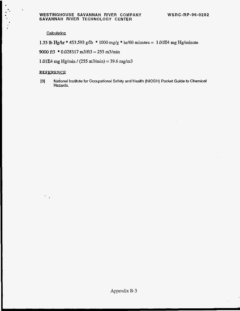
Maximum Elemental Hg Concentration in SRAT - 2.01 6 wt% dry SRAT Boilup Rate - 1000 Ibdhr Hg Steam Stripping Rate - 1.33 Ibdhr Hg Addition Rate into Process Room - equivalent to steam stripping rate Interlocks Fail to Shutdown Steam to SRAT and Initiate Cooling Water Flow to SRAT Process Room Air Flow - 9000 cfm Hg IDLH - 10 rng/m3 [3]
Appendix B-2
. a
a '
b
*
1
WESTINGHOUSE SAVANNAH RIVER COMPANY SAVANNAH RIVER TECHNOLOGY CENTER
W S RC-R P-96-0282
Calculation
1 33 lb Hgihr * 453 593 gab * 1000 mg/g * hr/60 minutes = l.OlE4 mg Hg/minute
9000 ft3 * 0.028317 m3/ft3 = 255 m3/min
1.01E4 mg Hg/min / (255 m3/min) = 39 -6 mg/m3
REFERENCE
[3] Naiional Institute for Occupational Safety and Health (NIOSH) Pocket Guide to Chemical Hazards.
Appendix B-3