vented gas log set models: vdy24/18, vdy30
TRANSCRIPT

Installation and Operating Instructions
Approved to ANSI Z21.60 / CSA 2.26
WARNINGSIf the information in this manual is not followed exactly, a fire or explosion may result causing property damage, personal injury or loss of life.
– Do not store or use gasoline or other flammable vapors and liquids in the vicinity of this or any other appliance.
– WHAT TO DO IF YOU SMELL GAS • Do not try to light any appliance. • Do not touch any electrical switch; do not
use any phone in your building. • Immediately call your gas supplier from
a neighbor's phone. Follow the gas supplier's instructions.
• If you cannot reach your gas supplier, call the fire department.
– Installation and service must be performed by a qualified installer, service agency or the gas supplier.
This gas log set is to be installed only in a solid-fuel burning fireplace with a working flue constructed of noncombustible material.
INSTALLER: Leave this manual with the appliance.CONSUMER: Retain this manual for future refer-ence.
VDY30D3R
VDY24/18D5
VDY24/18D2A
321999VDY log cover
Vented Gas Log SetModels: VDY24/18, VDY30
Hearth & Home Technologies • VDY 24/18/30 Gas Log Heater Install/Owner's Manual • 32D1999 • Rev I • 05/21
"Duzy" Series

"Duzy" Gas Log Sets – The Look and Feel of a Real Wood Fire
2 Hearth & Home Technologies • VDY 24/18/30 Gas Log Heater Install/Owner's Manual • 32D1999 • Rev I • 05/21
Important Safety Information .................................... 3Getting Started ........................................................... 4 Check for Correct Parts .......................................... 4 Items Required for Installation ................................ 4Product Specifications ............................................... 4 Gas Pressures ........................................................ 4 Gas Specifications .................................................. 4 Ignition Controls ...................................................... 4 Minimum Hearth Dimensions .................................. 5 Damper Stop Installation ......................................... 5Placement in a Fireplace with a Restrictive Barrier 6Installation ................................................................... 7 Place and Secure Appliance ................................... 7 Assembly Procedure ............................................... 7 Gas Line Connection .............................................. 7Electrical Wiring - Millivolt .......................................... 9 Check System Operation ........................................ 9Log Placement .......................................................... 10 VDY24/18D2 ......................................................... 10 VDY30D2A ............................................................ 11 VDY24/18D3R ...................................................... 12 VDY30D3R ........................................................... 13 VDY24/18D5 ......................................................... 14 VDY30D5 .............................................................. 16 Glowing Ember Placement ................................... 18 Decorative Volcanic Rock Placement ................... 18Fireplace Draft Test .................................................. 18Flame Appearance .................................................... 19
CONTENTS
Operating Instructions ............................................. 20 For Your Safety Read Before Lighting ................. 20 Millivolt Control Lighting Instructions .................... 21 To Turn Off Gas to Heater ..................................... 21 Match Lighting Instructions ................................... 21Optional Remote Receiver (Millivolt) ....................... 22Cleaning and Servicing ............................................ 23Troubleshooting ....................................................... 24Service Parts .............................................................. 26Accessories ............................................................... 34Massachusetts Requirements .................................. 35Warranty ..................................................................... 36
Thank you and congratulations on your purchase of a Hearth & Home Technologies Log Set.
PLEASE READ THE INSTALLATION AND OPERATION INSTRUCTIONS BEFORE USING THE APPLIANCE!IMPORTANT: Read all instructions and warnings carefully before starting installation.
Failure to follow these instructions may result in a possible fire hazard and will void the warranty.
= Contains updated information.
►

3
"Duzy" Gas Log Sets – The Look and Feel of a Real Wood Fire
Hearth & Home Technologies • VDY 24/18/30 Gas Log Heater Install/Owner's Manual • 32D1999 • Rev I • 05/21
1. The installation, combustion and ventilation air must conform with local codes or, in the absence of local codes, with the National Fuel Gas Code, ANSI Z223.1.
2. This unit complies with ANSI Z21.60 • CSA 2.26 Dec-orative Gas Appliance for Installation in Solid-Fuel Burning Fireplace.
3. Installation and repair should be done by a qualified service person. Hearth & Home Technologies Vented Gas Logs must be installed only in a solid-fuel (wood) burning fireplace which can only be constructed of non-combustible material, with minimum venting requirements, see installation section.
4. To prevent malfunction, gas log set and flue should be cleaned at least annually by a professional service person. More frequent cleaning may be required due to excessive lint from carpeting, etc. It is imperative that control compartments, burners and circulating air passageways be kept clean.
5. Correct installation of the ceramic fiber logs, and annual cleaning are necessary to minimize problems with sooting. See log placement instructions for proper installation.
6. A damper clamp must be installed to provide the min-imum permanent vent opening to vent flue products, See installation instructions.
7. Never burn solid fuels in a fireplace where a gas log set is installed.
8. This appliance must not be used with glass doors in the closed position. Provisions for adequate com-bustion air must be provided, adequate combustion air usually results in all flames curling into the fireplace away from screen and up the flue.
9. Keep room area clear and free from combustible mate-rials, gasoline and other flammable vapors and liquids.
10. Children and adults should be alerted to the hazard of high surface temperature and should stay away to avoid burns or clothing ignition.
11. Young children should be carefully supervised when they are in the same room with the gas log set in oper-ation.
12. Do not place clothing or other flammable material near the fireplace when the gas logs are in use.
SAFETY INFORMATION
13. Do not use this gas log set if any part has been under-water. Immediately call a qualified service technician to inspect the gas logs and replace any part of the control system and any gas control which has been under water.
14. The gas log set and its individual shutoff valve must be disconnected from the gas supply piping system during any pressure testing of the gas supply piping system at test pressures in excess of 1/2 psig (3.5kPa).
15. The gas log set must be isolated from the gas supply piping system by closing its individual manual shutoff valve during any pressure testing of the gas supply piping system at test pressures equal to or less than 1/2 psig (3.5kPa).
16. FOR MASSACHUSETTS RESIDENTS ONLY: Installation of this vented gas log in the Commonwealth
of Massachusetts requires the damper be permanently removed or welded in the full open position. In addi-tion, a naturally vented gas log may not be installed in a bedroom or bathroom in the commonwealth of Massachusetts.
INSTALLERPlease leave these instructions with the appliance.
OWNERPlease retain these instructions for future reference.
WA
RN
ING
• Any change to this gas log set or its controls can be dangerous.
• Improper installation or use of the gas log set can cause serious injury or death from fire, burns, explosion or carbon monoxide poisoning.IM
POR
TAN
T Read these instructions carefully before installing or trying to operate this vent-free gas heater.
WA
RN
ING This appliance is for installation only in
a solid fuel burning fireplace (masonry fireplace or manufactured fireplace)
Installation and service of this appliance should be performed by qualified personnel. Hearth & Home Technologies recommends HHT Factory Trained or NFI certified professionals.
"Duzy" Gas Log Sets – The Look and Feel of a Real Wood Fire
4 Hearth & Home Technologies • VDY 24/18/30 Gas Log Heater Install/Owner's Manual • 32D1999 • Rev I • 05/21
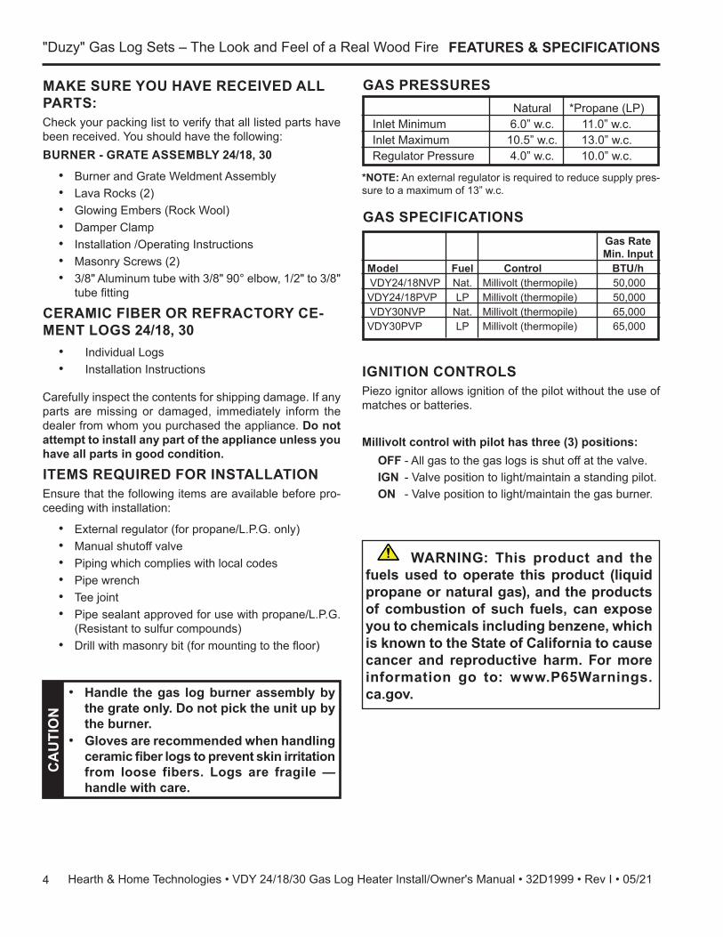
MAKE SURE YOU HAVE RECEIVED ALL PARTS: Check your packing list to verify that all listed parts have been received. You should have the following:BURNER - GRATE ASSEMBLY 24/18, 30
• Burner and Grate Weldment Assembly • Lava Rocks (2)• Glowing Embers (Rock Wool) • Damper Clamp• Installation /Operating Instructions • Masonry Screws (2)• 3/8" Aluminum tube with 3/8" 90° elbow, 1/2" to 3/8"
tube fitting
CERAMIC FIBER OR REFRACTORY CE-MENT LOGS 24/18, 30 • Individual Logs • Installation Instructions
Carefully inspect the contents for shipping damage. If any parts are missing or damaged, immediately inform the dealer from whom you purchased the appliance. Do not attempt to install any part of the appliance unless you have all parts in good condition.
ITEMS REQUIRED FOR INSTALLATIONEnsure that the following items are available before pro-ceeding with installation:
• External regulator (for propane/L.P.G. only)• Manual shutoff valve• Piping which complies with local codes • Pipe wrench• Tee joint • Pipe sealant approved for use with propane/L.P.G.
(Resistant to sulfur compounds)• Drill with masonry bit (for mounting to the floor)
FEATURES & SPECIFICATIONS
GAS PRESSURES Natural *Propane (LP) Inlet Minimum 6.0” w.c. 11.0” w.c. Inlet Maximum 10.5” w.c. 13.0” w.c. Regulator Pressure 4.0” w.c. 10.0” w.c.
*NOTE: An external regulator is required to reduce supply pres-sure to a maximum of 13” w.c.
CA
UTI
ON
• Handle the gas log burner assembly by the grate only. Do not pick the unit up by the burner.
• Gloves are recommended when handling ceramic fiber logs to prevent skin irritation from loose fibers. Logs are fragile — handle with care.
GAS SPECIFICATIONS Gas Rate Min. Input Model Fuel Control BTU/h VDY24/18NVP Nat. Millivolt (thermopile) 50,000 VDY24/18PVP LP Millivolt (thermopile) 50,000 VDY30NVP Nat. Millivolt (thermopile) 65,000 VDY30PVP LP Millivolt (thermopile) 65,000
IGNITION CONTROLS Piezo ignitor allows ignition of the pilot without the use of matches or batteries.
Millivolt control with pilot has three (3) positions:OFF - All gas to the gas logs is shut off at the valve.IGN - Valve position to light/maintain a standing pilot.ON - Valve position to light/maintain the gas burner.
WARNING: This product and the fuels used to operate this product (liquid propane or natural gas), and the products of combustion of such fuels, can expose you to chemicals including benzene, which is known to the State of California to cause cancer and reproductive harm. For more information go to: www.P65Warnings.ca.gov.

5
"Duzy" Gas Log Sets – The Look and Feel of a Real Wood Fire
Hearth & Home Technologies • VDY 24/18/30 Gas Log Heater Install/Owner's Manual • 32D1999 • Rev I • 05/21
PRODUCT SPECIFICATIONS
FP2725min hearth dims
D
A
BC
MINIMUM HEARTH DIMENSIONS
MILLIVOLT SERIES Model A B C D VDY24/18 18" 13Z\x" 26" 16" (457 mm) (343 mm) (660 mm) (406 mm) VDY30 24" 13Z\x" 32" 16" (610 mm) (343 mm) (813 mm) (406 mm)
Figure 1 - Minimum Hearth Dimensions
BEFORE INSTALLING THE APPLIANCE:• Turn off gas supply to Masonry fireplace or
manufactured wood burning firebox.• Have the fireplace floor and chimney professionally
cleaned to remove ashes, soot, creosote or other obstructions. Have this cleaning performed annually after installation.
• Seal any fresh air vents or ash clean-out doors locat-ed on floor or wall of fireplace. If not, drafting may cause pilot outage or sooting. Use a heat-resistant sealant.
INSTALL AND OPERATE THE APPLIANCE AS DIRECTED IN THIS MANUALDAMPER STOP INSTALLATIONA damper stop is provided with the unit. The damper stop must be installed as shown in Figure 2 to prevent full clo-sure of the fireplace damper blade and provide a minimum flue opening, per table below.Should the clamp not fit, or provide the required perma-nent opening from the table have the damper blade cut to provide minimum permanent opening or a permanent stop installed.
FP2727damper
Damper Stop
Damper
ST2727Figure 2 - Damper Stop Installation
FOR MASSACHUSETTS RESIDENTS ONLYInstallation of this vented gas log set in the Commonwealth of Massachusetts requires the damper be permanently removed or welded in the fully open position. In addition, a naturally vented gas log may not be installed in a bedroom or bathroom in the Commonwealth of Massachusetts.
Chimney Height VDY24/18 VDY30 6' 51 sq in 64 sq in 8' 51 sq in 64 sq in 10' 51 sq in 64 sq in 15' 39 sq in 51 sq in 20' 39 sq in 51 sq in 30' 30 sq in 51 sq in
The fireplace and gas logs function as a system. If the fireplace is spilling into the room (check with a match or smoke stick). Reposition the damper clamp until a positive draft is obtained, by opening the damper. If negative pressure in the home prevents having a positive draft contact your dealer.
WA
RN
ING
Minimum Opening Area of Chimney Damper for Venting

"Duzy" Gas Log Sets – The Look and Feel of a Real Wood Fire
6 Hearth & Home Technologies • VDY 24/18/30 Gas Log Heater Install/Owner's Manual • 32D1999 • Rev I • 05/21
IMPORTANT INFORMATION FOR THE IN-STALLATION OF THIS GAS LOG SETThe following are guidelines for placing a gas log set in a fireplace that has a restrictive barrier along the bottom front opening of the fireplace. Some examples of barriers are glass/screen door frames and sunken/recessed fireplaces. Height of Minimum Depth of Restriction (x) Fireplace/Firebox No Restriction 13Z\x” 0 to 3” 15” Greater than 3” **Any barrier greater than 3” placed in front of the gas log set is not recommended by the manufacturer.NOTE: Non combustible material such as refractory brick may be used to line the floor of the fireplace in order to raise the height of the gas log set in relation to a restrictive barrier. If the unit is raised, the minimum height dimension listed in the homeowner’s manual must not be exceeded.NOTE: If the log set is equipped with a remote receiver, a restrictive barrier may reduce the battery life by increasing the ambient temperature inside the fireplace. Placement of the receiver outside of the fireplace will extend the battery life.
X
FP2854logs in enclosure
Glass door frames with adjustable louvers should have the louvers fully open while the unit is in operation
Height of restrictive barrier caused by glass door frames, recessed fireplaces, etc. from the base or bottom surface of the unit. (Refer to Table)
Refer to Table
FP2854
Figure 3 -Reference Drawing of Log Set in an Enclosure
The log set should be placed against or as near as possible to the rear wall of the fireplace/firebox.
WA
RN
ING
Barriers such as the bottom of a glass door frame placed in front of a gas log set can change the air flow characteristics of the fireplace which in turn can cause the unit to overheat and malfunction. Any deviation from the installation guidelines on this sheet will potentially void the warranty.
7
"Duzy" Gas Log Sets – The Look and Feel of a Real Wood Fire
Hearth & Home Technologies • VDY 24/18/30 Gas Log Heater Install/Owner's Manual • 32D1999 • Rev I • 05/21
PLACE AND SECURE APPLIANCE
INSTALLATION
ASSEMBLY PROCEDURE1. Center the gas log unit in the fireplace or firebox. Make
certain the front feet of the grate sit inside the front edge of the fireplace or firebox.
2. Refer to Figure 4 for hole locations. After centering the grate correctly, mark the hole positions on the fireplace/firebox floor. Drill two (2) 5/32" diameter holes approx-imately 1Z\x" deep.
3. Anchor the grate to the fireplace/firebox floor using the screws provided. Figure 4
Proper installation of the grate is essential to prevent any movement of the gas logs and controls during operation.
WA
RN
ING You must secure the gas log heater to the
fireplace floor. Properly securing the grate prevents movement of the entire unit when you adjust the controls. Grate movement could cause a gas leak.
Figure 4 - Securing Heater to Floor of Fireplace/Firebox
Left Side Mounting Hole
Right Side Mounting Hole
FP2855secure burner
FP2855
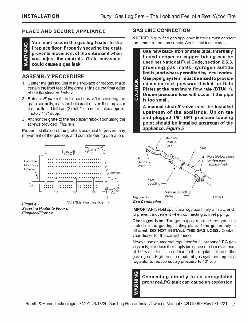
GAS LINE CONNECTIONNOTICE: A qualified gas appliance installer must connect the heater to the gas supply. Consult all local codes.
CA
UTI
ON
Use new black iron or steel pipe. Internally tinned copper or copper tubing can be used per National Fuel Code, section 2.6.3, providing gas meets hydrogen sulfide limits, and where permitted by local codes. Gas piping system must be sized to provide minimum inlet pressure (Listed on Data Plate) at the maximum flow rate (BTU/Hr). Undue pressure loss will occur if the pipe is too small.A manual shutoff valve must be installed upstream of the appliance. Union tee and plugged 1/8" NPT pressure tapping point should be installed upstream of the appliance. Figure 5
FP2371gas connect
Stainless Flexible Tube Pipe
Possible Locations for Pressure Tapping Point
To Heater Valve
Pipe Coupling
Manual Shutoff Valve FP2371Figure 5 -
Gas Connection
IMPORTANT: Hold appliance regulator firmly with a wrench to prevent movement when connecting to inlet piping.Check gas type: The gas supply must be the same as stated on the gas logs rating plate. If the gas supply is different, DO NOT INSTALL THE GAS LOGS. Contact your dealer for the correct model.Always use an external regulator for all propane/LPG gas logs only, to reduce the supply tank pressure to a maximum of 13" w.c. This is in addition to the regulator fitted to the gas log set. High pressure natural gas systems require a regulator to reduce supply pressure to 10" w.c.
WA
RN
ING Connecting directly to an unregulated
propane/LPG tank can cause an explosion

"Duzy" Gas Log Sets – The Look and Feel of a Real Wood Fire
8 Hearth & Home Technologies • VDY 24/18/30 Gas Log Heater Install/Owner's Manual • 32D1999 • Rev I • 05/21
GAS LINE CONNECTION
The heater gas inlet connection is 3/8" NPT at the reg-ulator, inlet on the right side facing the gas log. If a left side connection is required, the connecting pipe may be led under the rear of the gas logs or behind the grate for connection to the inlet.NOTE: The millivolt valve has an internal regulator, thus the incoming gas line connects directly to the valve.Test all gas joints from the gas meter to the appliance regulator for leaks using a gas analyzer or soap and water solution after completing connection. DO NOT USE AN OPEN FLAME.Check the gas pressure with the appliance burning.
MANUAL CONTROL Figure 6The pressure regulator is preset and locked to discourage tampering. If the pressure is not as specified, replace with the correct part from the parts list in this manual.Remove 1/8" NPT plug, located on side of regulator body. Install fitting and tubing to pressure gauge. After taking pressure reading, re-install test plug. Check for gas leaks.
FP2499manual valve
NPT Test Plug
FP2499Figure 6 - Manual Control Pressure Test Point Location
MILLIVOLT CONTROL Figure 7The valve regulator controls the burner pressure which should be checked at the pressure test point. Turn captured screw counter clockwise 2 or 3 turns and then place tubing to pressure gauge over test point (Use test point labeled “OUT”). After taking pressure reading, be sure and turn captured screw clockwise firmly to re-seal. Do not over torque. Check for gas leaks.
FP2856millivolt valve
Test Port "Out"
FP2856
Figure 7 - Pressure Test Point Location

9
"Duzy" Gas Log Sets – The Look and Feel of a Real Wood Fire
Hearth & Home Technologies • VDY 24/18/30 Gas Log Heater Install/Owner's Manual • 32D1999 • Rev I • 05/21
ELECTRICAL WIRING
Label all wires prior to disconnection when servicing controls. Wiring errors can cause improper and dangerous operation. Verify proper operation after servicing.W
AR
NIN
G
FP2857millivolt wiring
THTP
TP
TH
Optional Wall Switch or Remote Receiver
Switch
Millivolt Valve
Pilot
Figure 8 - Wiring Diagram
FP2857
The Millivolt (thermopile) is a self powered combination gas control that does not require 110VAC to operate. See Figure 8 and installation instructions provided with option-al wall switch or remote control for wiring instructions. A maximum length of 15 feet of 18awg two conductor wire is to be used for wall switch. Note switches must be suitable for millivolt operation.
CHECKING SYSTEM OPERATIONThe millivolt system and individual components may be checked with a millivolt meter having a 1-1000 mV range. Conduct each check shown in chart by connecting meter test leads to terminals as indicated.
A. Complete Millivolt System Check (“A” Reading - Contacts CLOSED - Control knob “ON”
- Main burner should turn ON)1. If reading is more than 100 millivolts and the au-
tomatic valve still does not come on, replace the control.
2. If the closed circuit reading (“A” reading) is less than 100 millivolts, determine cause for low read-ing, proceed to Section B.
B. Thermopile Output Reading Check (“B” Reading - Contacts OPEN - Main burner OFF
1. 325 millivolts minimum. If the minimum millivolt reading is not obtainable, readjust pilot for maxi-mum millivolt output. If millivolt reading is still below minimum specified, replace thermopile.
Connect Meter Check Meter Leads Reading Test To Test To Terminals Should Be A Complete TH & THTP Minimum System 100mV B Thermopile TP & THTP Minimum Output 325mV

"Duzy" Gas Log Sets – The Look and Feel of a Real Wood Fire
10 Hearth & Home Technologies • VDY 24/18/30 Gas Log Heater Install/Owner's Manual • 32D1999 • Rev I • 05/21
LOG PLACEMENTIMPORTANT: Remove logs, handling carefully by holding gently at each end. Gloves are recommended to prevent skin irritation from ceramic fibers. If skin becomes irritated, wash gently with soap and water.
LOG PLACEMENT
DUZY II VDY24/18D2A1. Install the rear log (#1) on the two locating pins of base.
Figure 9. Visually check to verify the log is securely placed on the pins and in contact with the grate. Figure 10
LG972VDY24_18D2 base
Locator Pins
Control Cover
LG972
Figure 9
LG971VDY24_18D2A rear log
Rear Log #1
LG971Figure 10
2. Install the right log (#2) on top of the control cover. Slide the log back until touching the rear log (#1). Visually check to verify the log is resting on the grate and control cover. Figure 11
3. Install the left log (#3) with its bottom groove resting on the right side of the grate bar. Slide the log back until touching the rear log (#1). Visually check to verify the log is resting on the grate. Figure 12
LG973VDY24_18D2A right log
Right Log #2
LG973Figure 11
LG974VDY24_18D2A left log
Left Log #3
Bottom GrooveLG975
Figure 12
4. Install the top log (#4) with the base sitting on the rear log (#1) and the top sitting on log (#4). Visually check to verify the log is resting on the rear log (#1) and left log (#3). Figure 13
LG975VDY24_18D2A top log
Top Log #4
Figure 13 LG975

11
"Duzy" Gas Log Sets – The Look and Feel of a Real Wood Fire
Hearth & Home Technologies • VDY 24/18/30 Gas Log Heater Install/Owner's Manual • 32D1999 • Rev I • 05/21
LOG PLACEMENT
DUZY II VDY30D2A LOG PLACEMENT1. Install the rear log (#1) on the two locating pins of base.
Figure 14. Visually check to verify the log is securely placed on the pins and in contact with the grate. Figure 15
LG976VDY30D2A base
Locator Pins
Control Cover
LG976
Figure 14
LG977VDY30D2 rear log
Rear Log #1
LG977Figure 15
2. Install the right log (#2) on top of the control cover. Slide the log back until touching the rear log (#1). Visually check to verify the log is resting on the grate and control cover. Figure 16
3. Install the left log (#3) with its bottom groove resting on the right side of the grate bar. Slide the log back until touching the rear log (#1). Visually check to verify the log is resting on the grate. Figure 17
4. Install the top log (#4) with the base sitting on the rear log (#1) and the top sitting on log (#4). Visually check to verify the log is resting on the rear log (#1) and left log (#3). Figure 18
LG978VDY30D2 right log
Right Log #2
Figure 16LG978
LG979VDY30D2 left log
Left Log #3
Bottom GrooveLG979
Figure 17
LG980VDY30D2 top log
Top Log #4
LG980
Figure 18

"Duzy" Gas Log Sets – The Look and Feel of a Real Wood Fire
12 Hearth & Home Technologies • VDY 24/18/30 Gas Log Heater Install/Owner's Manual • 32D1999 • Rev I • 05/21
DUZY III VDY24/18D3R LOG PLACEMENT1. Align pins on bottom of rear log #1 with pins on grate
bar and place on grate. Figures 19 and 20
LOG PLACEMENT
LG972VDY24_18D2 base
Locator Pins
Control Cover
LG972
Figure 19
LG981VDY2418D3R rear log
Rear Log #1
LG981Figure 202. Place front left log #2 on left front of grate bar aligning
cutout in bottom of log with grate bar. Figure 21 3. Place front right log #3 on right front of grate bar aligning
cutout in bottom of log with grate bar. Make sure log #3 touches log #1. Figure 21
4. Place back end top middle log #4 on log #1. Press the side of log #4 against raised area of log #1. Align notch in front end of #4 with grate bar. Figure 22
5. Rest top right log #5 on log #3. Figure 236. Align top left log #6 with notches on log #2 and log #4.
Figure 23
LG983VDY2418D3R front right log
Front Left Log #2
Front Right Log #3
CutoutLG983
Figure 21
LG984VDY2418D3R top mid log
Top Middle Log #4
NotchLG984
Figure 22
LG985VDY2418D3R top rt lt logs
Top Right Log #5
Top Left Log #6
LG985Figure 23
13
"Duzy" Gas Log Sets – The Look and Feel of a Real Wood Fire
Hearth & Home Technologies • VDY 24/18/30 Gas Log Heater Install/Owner's Manual • 32D1999 • Rev I • 05/21
LOG PLACEMENT
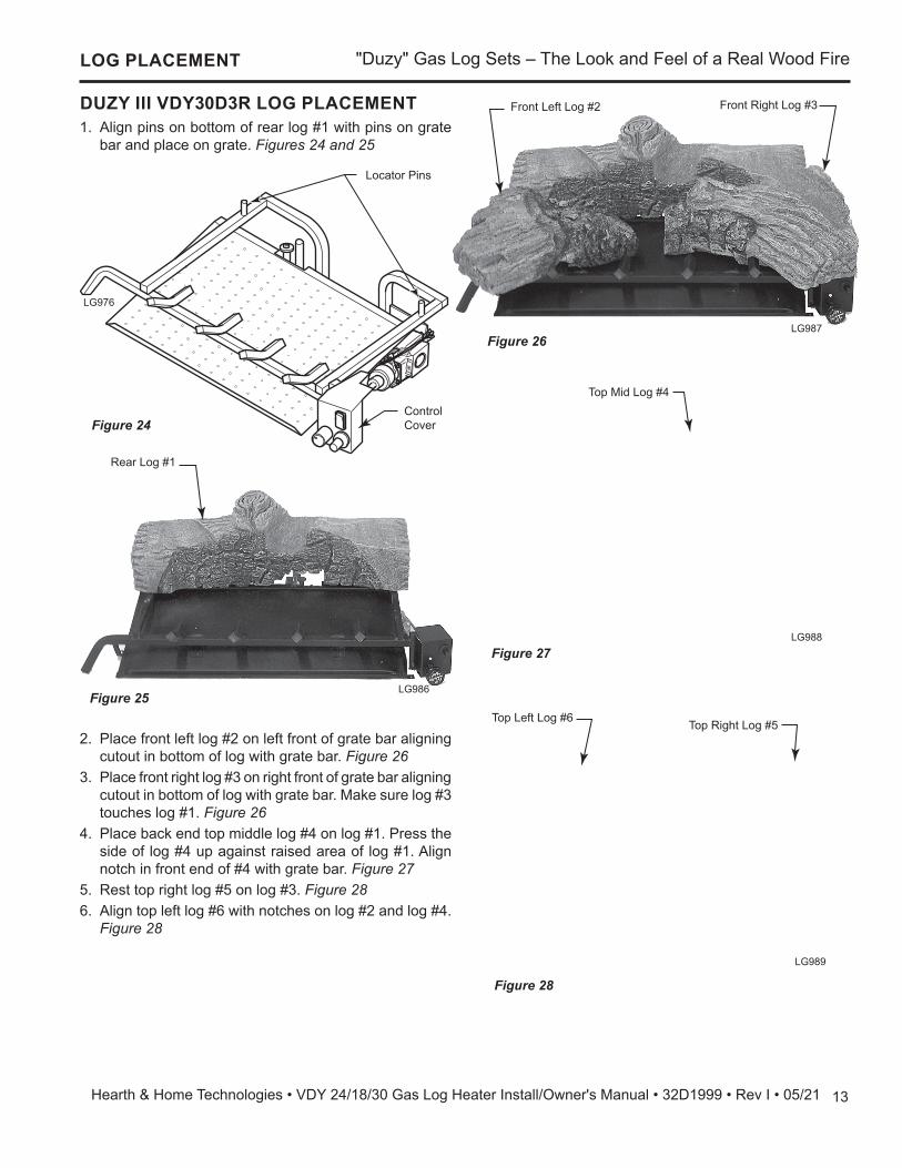
DUZY III VDY30D3R LOG PLACEMENT1. Align pins on bottom of rear log #1 with pins on grate
bar and place on grate. Figures 24 and 25
LG976VDY30D2A base
Locator Pins
Control Cover
LG976
Figure 24
LG986 VDY30D3R rear log
Rear Log #1
LG986Figure 25
2. Place front left log #2 on left front of grate bar aligning cutout in bottom of log with grate bar. Figure 26
3. Place front right log #3 on right front of grate bar aligning cutout in bottom of log with grate bar. Make sure log #3 touches log #1. Figure 26
4. Place back end top middle log #4 on log #1. Press the side of log #4 up against raised area of log #1. Align notch in front end of #4 with grate bar. Figure 27
5. Rest top right log #5 on log #3. Figure 286. Align top left log #6 with notches on log #2 and log #4.
Figure 28
LG987 VDY30D3R front logs
Front Left Log #2 Front Right Log #3
LG987Figure 26
LG988VDY30D3R top mid log
Top Mid Log #4
LG988Figure 27
LG989 VDY30D3R top logs
Top Left Log #6 Top Right Log #5
LG989
Figure 28

"Duzy" Gas Log Sets – The Look and Feel of a Real Wood Fire
14 Hearth & Home Technologies • VDY 24/18/30 Gas Log Heater Install/Owner's Manual • 32D1999 • Rev I • 05/21
DUZY V LOG VDY24/18D51. Place back log (#1) on back of base aligning two (2) pins
on base with holes in bottom of log. Figures 29 and 30
LOG PLACEMENT
LG972VDY24_18D2 base
Locator Pins
Control Cover
LG972
Figure 30
LG1000VDY2418D5 BACK LOG
Back Log #1
LG1000
Figure 29
LG1001VDY2418D5 bottom logs
Bottom Left Log #3Bottom Right Log #2
LG1001Figure 31
2. Placed bottom right log (#2) on right side of grate. Figure 31
3. Place bottom left log (#3) on left side of grate. Figure 31

15
"Duzy" Gas Log Sets – The Look and Feel of a Real Wood Fire
Hearth & Home Technologies • VDY 24/18/30 Gas Log Heater Install/Owner's Manual • 32D1999 • Rev I • 05/21
LOG PLACEMENT
LG1002VDY2418D5 top rt lt logs
Middle Left Log #4
Middle Right Log #5
LG1002
Figure 32
4. Place one end of middle left log (#4) on bottom left log. Rest other end of middle left log (#4) behind middle right log. Figure 32
5. Place middle right log (#5) on top of bottom right log. Figure 32
6. Rest top right log (#6) on back log and bottom right log. Figure 33
7. Place top left log (#7) on bottom left log. Figure 33
LG1004VDY2418D5 front mid log
First Grate Prong Second Grate Prong
Front Middle Log #8
LG1004
Figure 34
8. Place front middle log (#8) between the first and second prongs. Figure 34
LG1003VDY2418D5 top left log
Top Left Log #7
LG1003
Figure 33
Top Right Log #6

"Duzy" Gas Log Sets – The Look and Feel of a Real Wood Fire
16 Hearth & Home Technologies • VDY 24/18/30 Gas Log Heater Install/Owner's Manual • 32D1999 • Rev I • 05/21
DUZY V VDY30D5 LOG PLACEMENT1. Place back log (#1) on back of base aligning two (2) pins
on base with holes in bottom of log. Figures 35 and 36
LOG PLACEMENT
LG976
LG976VDY30D2A base
Locator Pins
Control Cover
Figure 35
LG1005VDY30D5 back log
Back Log #1
LG1005
Figure 36
LG1006VDY30D5 bottom logs
Bottom Left Log #3
Bottom Right Log #2LG1006
Figure 37
2. Place bottom right log (#2) on right side of grate in front of back log. Figure 37
3. Place bottom left log (#3) on left side of grate in front of back log. Figure 37
LG1007VDY30D5 mid left log
Middle Left Log #4
LG1007Figure 38
4. Place middle left log (#4) on top of bottom left log. Figure 38

17
"Duzy" Gas Log Sets – The Look and Feel of a Real Wood Fire
Hearth & Home Technologies • VDY 24/18/30 Gas Log Heater Install/Owner's Manual • 32D1999 • Rev I • 05/21
LOG PLACEMENT
LG1008VDY30D5 mid right log
Middle Right Log #5
LG1008
Figure 39
5. Place middle right log (#5) on top of bottom right log. Figure 39
LG1009VDY30D5 top logs
Top Left Log #7Top Right Log #6
LG1009
Figure 40
6. Place top right log (#6) on middle right log and back log. Figure 40
7. Place top left log (#7) on bottom left log and middle left log. Figure 40
LG1010VDY30D5 middle front log
Middle Front Log #8
LG1010
Figure 41
8. Place middle front log (#8) between second and third grate bars. Figure 41

"Duzy" Gas Log Sets – The Look and Feel of a Real Wood Fire
18 Hearth & Home Technologies • VDY 24/18/30 Gas Log Heater Install/Owner's Manual • 32D1999 • Rev I • 05/21
PLACEMENT OF THE GLOWING EMBERSCover the burner pan with glowing embers (rock wool) provided. Tear pieces approximately 1/2" in size (roughly the size of a nickel) and cover the burner evenly.DO NOT…1. Pile the rock wool too thickly on pan.2. Place rock wool higher than the top of the front grate
bar.3. Cover the pilot with rock wool. PLACEMENT OF DECORATIVE VOLCANIC ROCKSprinkle volcanic rock in front of front glowing embers and to both sides. DO NOT SPRINKLE ON BURN-ERS, PILOT OR LOGS.IMPORTANT: FIREPLACE DRAFT TEST DURING INI-TIAL INSTALLATIONIt is critical to verify that your chimney is drafting properly because the fireplace and gas logs function as a system.Although Hearth & Home Technologies goes to great lengths to design vented gas log sets that minimize sooting, all vented log sets will soot over time. Soot-ing normally appears as areas of a black powder-like substance on the logs. It is important to periodically clean and inspect the logs per the cleaning and ser-vicing section of the manual.
FIREPLACE DRAFT TEST
FIREPLACE DRAFT TEST METHODTo determine if your fireplace is drafting properly, turn the log set on. After the log set has been burning for about 10 minutes, place a match or smoke stick along the top and sides of the fireplace opening. If the flame or smoke is not pulled into the fireplace, then the fireplace is not venting properly. At this point the damper stop should be adjusted so that the damper opening is increased. If the problem remains after the open area of the damper is increased, then the fireplace system should be professionally inspect-ed to determine if your firebox/chimney is venting properly.
WA
RN
ING
Fireplace systems that do not draft properly can increase the amount of soot produced by normal operation of the log set and in extreme cases can cause soot to be deposited within the room. This effect can be a sign of a blocked chimney, a faulty vent system or the result of negative pressure within the home. The dealer should be able to diagnose if a problem exists and be able to provide a solution to improve the venting of the fireplace.

19
"Duzy" Gas Log Sets – The Look and Feel of a Real Wood Fire
Hearth & Home Technologies • VDY 24/18/30 Gas Log Heater Install/Owner's Manual • 32D1999 • Rev I • 05/21
FLAME APPEARANCE
CHECKING BURNER FLAMESIn normal operation at full rate after approximately 15 min-utes, the following flame appearance should be observed.
LG1011VDY burner flame
Rear f lame should be yellow and extend vertically. Maximize spacing on top logs.
Ember bed should have a yellow/orange glow. LG1011
Burner flames should become yellow as they contact embers on the face of the log. The log face will glow a bright reddish orange.
Figure 42 - Proper Flame Appearance
MILLIVOLT CONTROL WITH PILOT ONLYPILOT FLAME APPEARANCEThe pilot flame must always be present when appliance is in operation. It should touch the thermocouple or ther-mopile body.
INITIAL STARTUPDuring manufacturing, fabricating and shipping, various components of this appliance are treated with certain oils, films or bonding agents. These chemicals are not harmful, but may produce annoying smoke and smells as they are burned off during the initial operation of the appliance. The initial break-in operation should last 2-3 hours with the burner at the highest setting. The appliance must not be used with glassed doors in the closed position. This can result reduced combustion and overheating.
FP2859millivolt pilot flame
FP2859
Thermopile
Figure 43 - Correct Pilot Flame Appearance
Millivolt Control Pilot

"Duzy" Gas Log Sets – The Look and Feel of a Real Wood Fire
20 Hearth & Home Technologies • VDY 24/18/30 Gas Log Heater Install/Owner's Manual • 32D1999 • Rev I • 05/21
OPERATING INSTRUCTIONS
SAFETY INSTRUCTION FOR MANUAL AND MILLIVOLT CONTROL WITH PILOT
FOR YOUR SAFETY READ BEFORE LIGHTING A. This appliance is equipped with an ignition
device which automatically lights the pilot. B. BEFORE OPERATING smell all around the
appliance area for gas. Be sure to smell next to the floor because some gas is heavier than air and will settle on the floor.
WHAT TO DO IF YOU SMELL GAS: • Do not attempt to light any appliance. • Do not touch any electric switch; do not
use any phone in your building. • Immediately call your gas supplier from a
neighbor's phone. Follow the gas supplier's instructions.
• If you cannot reach your gas supplier, call the fire department.
WA
RN
ING If you do not follow these instruction
exactly, a fire or explosion may result causing property damage, personal injury or loss of life.
C. Use only your hand to push in, or turn the gas control knob. Never use tools. If the knob will not push in or turn by hand, don't try to repair it. Call a qualified service technician. Force or at-tempted repair may result in a fire or explosion.
D. Do not use this appliance if any part of it has been under water. Immediately call a qualified service technician to inspect the appliance and to replace any part of the control system and any gas control that has been under water.

21
"Duzy" Gas Log Sets – The Look and Feel of a Real Wood Fire
Hearth & Home Technologies • VDY 24/18/30 Gas Log Heater Install/Owner's Manual • 32D1999 • Rev I • 05/21
OPERATING INSTRUCTIONS
1. Turn control knob clockwise to “OFF” po-sition to completely shut off the heater.
2. If applicable: Turn ON/OFF switch to “OFF” posi-tion.
1. STOP! Read the safety information label.2. Make sure the manual shutoff valve is fully
open.3. This gas log set is equipped with an ignition
device (piezo) which automatically lights the pilot. If piezo ignitor does not light the pilot, see instructions for Match Lighting below.
4. Turn gas control knob clockwise to the “OFF” position, and turn ON/OFF switch to “OFF” position.
5. Wait (5) minutes to clear out any gas. Then smell for gas, including near the floor. If you smell gas, STOP! Follow “B” in the safety information label. If you don't smell gas, go to next step.
6. From “OFF” position, turn the gas control knob counterclockwise to “IGN” position. Push in control knob for 5 seconds.
1. Remove any items necessary for easy access to the pilot (for example: logs, screens, etc.).
2. Follow appropriate lighting instructions found previously. Instead of pushing and releasing the piezo button, light a match and hold the flame to the end of the pilot and ignite the pilot.
MILLIVOLT CONTROL LIGHTING INSTRUCTIONS
TO TURN OFF GAS TO HEATER
MATCH LIGHTING INSTRUCTIONS
WA
RN
ING
Wait 30 seconds before readjusting the heater when the control knob has been turned down to a lower setting.
FP2859millivolt pilot flame
Millivolt Pilot
FP2861millivolt control knob
FP2862on off switch
Control Knob On/Off Switch
7. With the control knob pushed in, push in and release the piezo ignitor button to light the pilot.
8. Continue pushing the control knob in for a further 60 seconds to prevent the flame detector from shutting off the gas while the probe is warming up. Release the control knob.
9. Turn gas control knob counterclockwise to the “ON” position.
10.After the pilot has been lit for one minute, the burners can be turned on. Turn the ON/OFF switch to “ON” position.
11.If the gas logs will not operate, follow the instruc-tions To Turn Off Gas To Heater and call your service technician or gas supplier.
3. If applicable: Turn off all electric power to the heater.
3. After control knob has been released and pilot stays lit, re-install any items that were removed for pilot access.
4. Call a qualified service technician for repair or replacement of the piezo ignitor.
"Duzy" Gas Log Sets – The Look and Feel of a Real Wood Fire
22 Hearth & Home Technologies • VDY 24/18/30 Gas Log Heater Install/Owner's Manual • 32D1999 • Rev I • 05/21
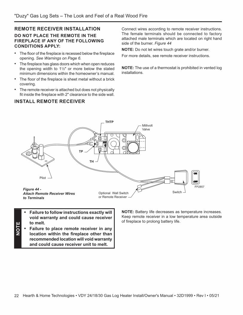
REMOTE RECEIVER INSTALLATIONDO NOT PLACE THE REMOTE IN THE FIREPLACE IF ANY OF THE FOLLOWING CONDITIONS APPLY:• The floor of the fireplace is recessed below the fireplace
opening. See Warnings on Page 6. • The fireplace has glass doors which when open reduces
the opening width to 1Z\x" or more below the stated minimum dimensions within the homeowner’s manual.
• The floor of the fireplace is sheet metal without a brick covering.
• The remote receiver is attached but does not physically fit inside the fireplace with 2" clearance to the side wall.
INSTALL REMOTE RECEIVER
FP2857millivolt wiring
THTP
TP
TH
Optional Wall Switch or Remote Receiver
Switch
Millivolt Valve
Pilot
Figure 44 - Attach Remote Receiver Wires to Terminals
FP2857
NO
TE
• Failure to follow instructions exactly will void warranty and could cause receiver to melt.
• Failure to place remote receiver in any location within the fireplace other than recommended location will void warranty and could cause receiver unit to melt.
NOTE: Battery life decreases as temperature increases. Keep remote receiver in a low temperature area outside of fireplace to prolong battery life.
Connect wires according to remote receiver instructions. The female terminals should be connected to factory attached male terminals which are located on right hand side of the burner. Figure 44 NOTE: Do not let wires touch grate and/or burner. For more details, see remote receiver instructions.
NOTE: The use of a thermostat is prohibited in vented log installations.

23
"Duzy" Gas Log Sets – The Look and Feel of a Real Wood Fire
Hearth & Home Technologies • VDY 24/18/30 Gas Log Heater Install/Owner's Manual • 32D1999 • Rev I • 05/21
CLEANING AND SERVICING
Remove logs, handling carefully by holding gently at each end. Gloves are recommended to prevent skin irritation from ceramic fibers. If skin becomes irritated, wash gently with soap and water. See manual for correct log placement.PERIODIC CLEANING - SEE PARTS DIAGRAM FOR LOCATION OF ITEMS DISCUSSED BELOW.
• Do not use cleaning fluid to clean logs or any part of gas logs.
• Logs - brush with soft bristle brush or vacuum with brush attachment.
• Vacuum loose particles and dust from the control and grate weldment.
• Inspect and clean burner air intake holes. Remove lint or particles with vacuum or brush. Failure to keep air intake holes clean will result in sooting and poor combustion.
• If embers (rock wool) have turned a rust color and become brittle, remove old embers (rock wool) from log set. Replace with new rock wool. Rock wool can be purchased from your local dealer. See log place-ment section for placement of embers.
ANNUAL CLEANING/INSPECTION - SEE PARTS
WA
RN
ING Turn off gas logs and allow to cool before
cleaning. Disconnect electrical power if applicable before cleaning or servicing.
DIAGRAM FOR LOCATION OF ITEMS DISCUSSED BELOW.
• Inspect and clean all burner ports.• Verify burner and pilot flame pattern and log place-
ment for proper operation.• Verify smooth and responsive ignition of burner.• Inspect and clean chimney.• Inspect and clean burner air intake holes. Remove
lint or particles with vacuum or brush. Failure to keep air intake holes clean will result in sooting and poor combustion.

"Duzy" Gas Log Sets – The Look and Feel of a Real Wood Fire
24 Hearth & Home Technologies • VDY 24/18/30 Gas Log Heater Install/Owner's Manual • 32D1999 • Rev I • 05/21
TROUBLESHOOTINGW
AR
NIN
G Turn off appliance and allow to cool before cleaning. Only a qualified service person should service and repair the heater.
NOTE: All troubleshooting items are listed in order of operation.
ProblemWhen ignitor button is pressed, there is no spark at pilot.
Appliance produces un-wanted odors.
Appliance shuts off during use.
Gas odor even when control knob is in OFF position.
When ignitor button is pressed, there is spark at pilot, but no ignition.
Possible Cause1. Ignitor electrode positioned wrong.2. Ignitor electrode is broken.3. Ignitor electrode not connected to
ignitor cable.4. Ignitor cable pinched or wet. Keep
ignitor cable dry.5. Broken ignitor cable.6. Bad piezo ignitor.1. Appliance burning vapors from
paint, hair spray, glues, etc.2. Gas leak.3. Fireplace spilling.
1. Low line pressure.2. Pilot is partially clogged.3. Defective thermopile.1. Gas leak.2. Control valve defective.
1. Gas supply turned off or manual shutoff valve closed.
2. Control knob not in PILOT position.3. Control knob not pressed in while in
PILOT position.4. Air in gas lines when installed.
5. Pilot is clogged.6. Gas regulator setting is not correct.
Solution1. Replace ignitor.2. Replace ignitor.3. Reconnect ignitor cable.
4. Free ignitor cable if pinched by any met-al or tubing.
5. Replace ignitor cable.6. Replace piezo ignitor.1. Ventilate room. Stop using odor causing
products while heater is running.2. Locate and correct leaks.3. Check fireplace, adjust damper position
to eliminate spillage (backdraft).1. Locate and correct all leaks.2. Replace control valve.
1. Locate and correct all leaks.2. Replace control valve.
1. Turn on gas supply or open manual shutoff valve.
2. Turn control knob to PILOT position.3. Press in control knob while in PILOT
position.4. Continue holding down control knob.
Repeat igniting operation until air is removed.
5. Replace pilot assembly or get it serviced6. Replace gas regulator.

25
"Duzy" Gas Log Sets – The Look and Feel of a Real Wood Fire
Hearth & Home Technologies • VDY 24/18/30 Gas Log Heater Install/Owner's Manual • 32D1999 • Rev I • 05/21
TROUBLESHOOTING
Problem Possible Cause SolutionW
AR
NIN
G If the gas quality is bad, your pilot may not stay lit, the burners may produce soot and the heater may backfire when lit. If the gas quality or pressure is low, contact your local gas supplier immediately.
Pilot lights, but flame goes out when control knob is released.
One or both burners do not light after pilot is lit.
Burner backfires during combustion.
Slight smoke or odor during initial operation.
Logs appear to smoke after initial operation.
Heater produces a whis-tling noise when burner is lit.
No gas to pilot.
1. Control knob not fully pressed in.2. Control knob not pressed in long
enough.3. Manual shutoff valve not fully open.1. Burner orifice is clogged or damaged2. Burner is damaged.3. Gas regulator defective.1. Manifold Pressure is too low.2. Burner orifice is clogged.1. Burner orifice is clogged or dam-
aged.2. Burner is damaged.3. Gas regulator is defective.1. Vapors from paint or curing process
of logs.
1. Turning control knob to HIGH posi-tion when burner is cold.
2. Air in gas line.
3. Dirty or partially clogged burner orifices.
1. LP regulator shut down due to inlet pressure too high.
1. Press in control knob fully.2. After ODS/pilot lights, keep control knob
pressed in for 30 seconds.3. Fully open manual shutoff valve.1. Clean burner or replace burner orifice.2. Replace burner orifice.3. Contact qualified service person.1. Contact local gas company.2. Clean burner or replace burner orifice.1. Clean burner or replace burner orifice.
2. Replace burner.3. Replace gas regulator.1. Problem will stop after a few hours of
operation. 2. Log heater is intended to be smokeless.
Turn OFF heater and call qualified ser-vice person.
1. Turn control knob to ON position and let warm up for a minute.
2. Operate burner until air is removed from line. Have gas line checked by local gas company.
3. Clean burner or replace burner orifice.
1. Verify LP tank regulator is installed and set at 11” to 13” w.c.
2. Replace regulator on heater.

"Duzy" Gas Log Sets – The Look and Feel of a Real Wood Fire
26 Hearth & Home Technologies • VDY 24/18/30 Gas Log Heater Install/Owner's Manual • 32D1999 • Rev I • 05/21
SERVICE PARTS
Service Parts DUZYBeginning Manufacturing Date: N/A Ending Manufacturing Date: Active
IMPORTANT: THIS IS DATED INFORMATION. Parts must be ordered from a dealer or distributor. Hearth and Home Technologies does not sell directly to consumers. Provide model number and serial number when requesting service parts from your dealer or distributor.
Stocked at Depot
ITEM DESCRIPTION COMMENTS PART NUMBER
1Pilot Assembly (Manual Control)
NG 27D8972K YPropane 27D8971K Y
Pilot Assembly (Millivolt Control)NG SRV27D8974 Y
Propane SRV27D8973 Y2 Thermocouple/Thermopile Manual Control SRV28D0400
3 Control KnobManual Control SRV27D0602Millivolt Control SRV18D0603
4 Regulator (Manual Control)NG SRV24D0305 Y
Propane SRV24D0306 Y5 Control Valve (Manual Control) NG & Propane SRV27D8951 Y
6 Control Valve (Millivolt Control)NG 27D8006K Y
Propane 27D8005K YSwitch, On/Off (Millivolt Control) SRV32D0232 YWire Harness (Millivolt Control) SRV32D0240 Y
7Injector (Manual Control)
NG SRV32D0100 YPropane SRV32D0118
Injector (Millivolt Control)NG SRV32D0100 Y
Propane SRV32D0507Piezo Igniter SRV14D0503 Y
5/21
Duzy 24/18” Hearth Kit
VDY24/18NMP (Natural Gas Manual Control) - Ending Manufacturing Date: April 2019VDY24/18PMP (Propane Manual Control) - Ending Manufacturing Date: April 2019VDY24/18NVP (Natural Gas Millivolt Control) - ActiveVDY24/18PVP (Propane Millivolt Control) - Active
1
2
45
6
7
3
►

27
"Duzy" Gas Log Sets – The Look and Feel of a Real Wood Fire
Hearth & Home Technologies • VDY 24/18/30 Gas Log Heater Install/Owner's Manual • 32D1999 • Rev I • 05/21
SERVICE PARTS
Service Parts DUZYBeginning Manufacturing Date: N/A Ending Manufacturing Date: Active
IMPORTANT: THIS IS DATED INFORMATION. Parts must be ordered from a dealer or distributor. Hearth and Home Technologies does not sell directly to consumers. Provide model number and serial number when requesting service parts from your dealer or distributor.
Stocked at Depot
ITEM DESCRIPTION COMMENTS PART NUMBER
1Pilot Assembly (Manual Control)
NG 27D8972K YPropane 27D8971K Y
Pilot Assembly (Millivolt Control)NG SRV27D8974 Y
Propane SRV27D8973 Y2 Thermocouple/Thermopile Manual Control SRV28D0400
3 Control KnobManual Control SRV27D0602Millivolt Control SRV18D0603
4 Regulator (Manual Control)NG SRV24D0305 Y
Propane SRV24D0306 Y5 Control Valve (Manual Control) NG & Propane SRV27D8951 Y
6 Control Valve (Millivolt Control)NG 27D8006K Y
Propane 27D8005K YSwitch, On/Off (Millivolt Control) SRV32D0232 YWire Harness (Millivolt Control) SRV32D0240 Y
7Injector (Manual Control)
NG 32D0090Propane SRV32D0113
Injector (Millivolt Control)NG SRV32D0090
Propane SRV32D0117Piezo Igniter SRV14D0503 Y
5/21
Duzy 30” Hearth Kit
VDY30NMP (Natural Gas Manual Control) - Ending Manufacturing Date: April 2019VDY30NVP (Natural Gas Millivolt Control) - ActiveVDY30PMP (Propane Manual Control) - Ending Manufacturing Date: April 2019VDY30PVP (Propane Millivolt Control) - Active
1
2
45
6
7
3

"Duzy" Gas Log Sets – The Look and Feel of a Real Wood Fire
28 Hearth & Home Technologies • VDY 24/18/30 Gas Log Heater Install/Owner's Manual • 32D1999 • Rev I • 05/21
SERVICE PARTS
Service Parts VDY24/18D2ABeginning Manufacturing Date: N/A Ending Manufacturing Date: Active
IMPORTANT: THIS IS DATED INFORMATION. Parts must be ordered from a dealer or distributor. Hearth and Home Technologies does not sell directly to consumers. Provide model number and serial number when requesting service parts from your dealer or distributor.
Stocked at Depot
ITEM DESCRIPTION COMMENTS PART NUMBER1 Rear Log 32D0400K2 Right Log 32D0401K3 Left Log 32D0402K4 Top Log 32D0403K
5/21
Duzy II 24”-18” Log Set
2
1
3
4

29
"Duzy" Gas Log Sets – The Look and Feel of a Real Wood Fire
Hearth & Home Technologies • VDY 24/18/30 Gas Log Heater Install/Owner's Manual • 32D1999 • Rev I • 05/21
SERVICE PARTS
Service Parts VDY30D2ABeginning Manufacturing Date: N/A Ending Manufacturing Date: Active
IMPORTANT: THIS IS DATED INFORMATION. Parts must be ordered from a dealer or distributor. Hearth and Home Technologies does not sell directly to consumers. Provide model number and serial number when requesting service parts from your dealer or distributor.
Stocked at Depot
ITEM DESCRIPTION COMMENTS PART NUMBER1 Rear Log 32D0410K2 Right Log 32D0411K3 Left Log 32D0412K4 Top Log 32D0413K
5/21
Duzy II 30” Log Set
2
1
3
4

"Duzy" Gas Log Sets – The Look and Feel of a Real Wood Fire
30 Hearth & Home Technologies • VDY 24/18/30 Gas Log Heater Install/Owner's Manual • 32D1999 • Rev I • 05/21
SERVICE PARTS
Service Parts VDY24/18D3RBeginning Manufacturing Date: N/A Ending Manufacturing Date: Active
IMPORTANT: THIS IS DATED INFORMATION. Parts must be ordered from a dealer or distributor. Hearth and Home Technologies does not sell directly to consumers. Provide model number and serial number when requesting service parts from your dealer or distributor.
Stocked at Depot
ITEM DESCRIPTION COMMENTS PART NUMBER1 Rear Log SRV32D21182 Front Left Log SRV32D21173 Front Right Log SRV32D21164 Top Middle Log SRV32D21145 Top Right Log SRV32D21136 Top Left Log SRV32D2115
5/21
Duzy III 24”-18” Log Set
1
2
3
4
5
6

31
"Duzy" Gas Log Sets – The Look and Feel of a Real Wood Fire
Hearth & Home Technologies • VDY 24/18/30 Gas Log Heater Install/Owner's Manual • 32D1999 • Rev I • 05/21
Service Parts VDY30D3RBeginning Manufacturing Date: N/A Ending Manufacturing Date: Active
IMPORTANT: THIS IS DATED INFORMATION. Parts must be ordered from a dealer or distributor. Hearth and Home Technologies does not sell directly to consumers. Provide model number and serial number when requesting service parts from your dealer or distributor.
Stocked at Depot
ITEM DESCRIPTION COMMENTS PART NUMBER1 Rear Log SRV32D21242 Front Left Log SRV32D21233 Front Right Log SRV32D21224 Top Middle Log SRV32D21205 Top Right Log SRV32D21196 Top Left Log SRV32D2121
5/21
Duzy III 30” Log Set
1
2
3
4
5
6
SERVICE PARTS
"Duzy" Gas Log Sets – The Look and Feel of a Real Wood Fire
32 Hearth & Home Technologies • VDY 24/18/30 Gas Log Heater Install/Owner's Manual • 32D1999 • Rev I • 05/21
SERVICE PARTS
Service Parts VDY24/18D5Beginning Manufacturing Date: N/A Ending Manufacturing Date: Active
IMPORTANT: THIS IS DATED INFORMATION. Parts must be ordered from a dealer or distributor. Hearth and Home Technologies does not sell directly to consumers. Provide model number and serial number when requesting service parts from your dealer or distributor.
Stocked at Depot
ITEM DESCRIPTION COMMENTS PART NUMBER1 Back Log 32D3121K2 Bottom Right Log 32D3122K3 Bottom Left Log 32D3123K4 Middle Left Log 32D3124K5 Middle Right Log 32D3125K6 Top Right Log 32D3126K7 Top Left Log 32D3127K8 Front Middle Log 32D3128K
5/21
Duzy V 24”-18” Log Set
1
2
3
4 5
6
7
8

33
"Duzy" Gas Log Sets – The Look and Feel of a Real Wood Fire
Hearth & Home Technologies • VDY 24/18/30 Gas Log Heater Install/Owner's Manual • 32D1999 • Rev I • 05/21
SERVICE PARTS
Service Parts VDY30D5Beginning Manufacturing Date: N/A Ending Manufacturing Date: Active
IMPORTANT: THIS IS DATED INFORMATION. Parts must be ordered from a dealer or distributor. Hearth and Home Technologies does not sell directly to consumers. Provide model number and serial number when requesting service parts from your dealer or distributor.
Stocked at Depot
ITEM DESCRIPTION COMMENTS PART NUMBER1 Back Log 32D3131K2 Bottom Right Log 32D3132K3 Bottom Left Log 32D3133K4 Middle Left Log 32D3134K5 Middle Right Log 32D3135K6 Top Right Log 32D3136K7 Top Left Log 32D3137K8 Front Middle Log 32D3138K
5/21
Duzy V 30” Log Set
1
2
3
45
67
8
"Duzy" Gas Log Sets – The Look and Feel of a Real Wood Fire
34 Hearth & Home Technologies • VDY 24/18/30 Gas Log Heater Install/Owner's Manual • 32D1999 • Rev I • 05/21
ACCESSORIES
ACCESSORIESFlex Connector Flexcon30 All modelsWall Kit Switch w/20' wire MVWS MillivoltOn/Off Remote Control Kits RCB, RCM, TLM, WWTD MillivoltRemote Receiver Cover - Embers RRCE MillivoltRemote Receiver Cover - Metal RRCM MillivoltVolcanic Rock VR1000A All modelsDecorative Ceramic Fiber Embers EMBERS All modelsCeramic Fiber Cinders CINDERS All modelsRock Wool DV-RWA All Models

35
"Duzy" Gas Log Sets – The Look and Feel of a Real Wood Fire
Hearth & Home Technologies • VDY 24/18/30 Gas Log Heater Install/Owner's Manual • 32D1999 • Rev I • 05/21
NOTE REGARDING VENTED PRODUCTSThis product must be installed by a licensed plumber or gas fitter when installed within the Commonwealth of Massachusetts.Any residence with a direct vent product must have a CO detector installed in the residence.Installation of the fireplace or vented gas log in the State of Massachusetts requires the damper to be permanently removed or welded in the fully open position.In addition, a naturally vented gas log may not be installed in a bedroom or bathroom in the State of Massachusetts.Flex line installation must not exceed 36 inches and must have a T shutoff valve.
NOTE REGARDING VENT FREE PRODUCTSThis product must be installed by a licensed plumber or gas fitter when installed within the Commonwealth of Massachusetts.In addition, vent free products may not be installed in a bedroom or bathroom regardless of size or type in the State of Massachusetts.Flex line installation must not exceed 36 inches and must have a T shutoff valve.
CARBON MONOXIDE DETECTOR REQUIREMENTS(2) Revise 10.8.3 by adding the following additional requirements:(a) For all side wall horizontally vented gas fueled equipment installed in every dwelling, building or structure used in whole or in part for residential purposes, including those owned or operated by the Commonwealth and where the side wall exhaust vent termination is less than seven (7) feet above finished grade in the area of the venting, including but not limited to decks and porches, the following requirements shall be satisfied:1. Installation of carbon monoxide detectors. At the time of installation of the side wall horizontal vented gas fueled equipment, the installing plumber or gas fitter shall observe that a hard wired carbon monoxide detector with an alarm and battery back-up is installed on the floor level where the gas equipment is to be installed. In addition, the installing plumber or gas fitter shall observe that a battery operated or hard wired carbon monoxide detector with an alarm is installed on each additional level of the dwelling, building or structure served by the side wall horizontal vented gas fueled equipment. It shall be the responsibility of the property owner to secure the services of qualified licensed professionals for the installation of hard wired carbon monoxide detectors a. In the event that the side wall horizontally vented gas fueled equipment is installed in a crawl space or an attic, the hard wired carbon monoxide detector with alarm and battery back-up may be installed on the next adjacent floor level. b. In the event that the requirements of this subdivision can not be met at the time of completion of installation, the owner shall have a period of thirty (30) days to comply with the above requirements; provided, however, that during said thirty (30) day period, a battery operated carbon monoxide detector with an alarm shall be installed.
Massachusetts Residents Only — Please read and follow these special requirements
2. Approved Carbon Monoxide Detectors. Each carbon monoxide detector as required in accordance with the above provisions shall comply with NFPA 720 and be ANSI/UL 2034 listed and IAS certified.3. Signage. A metal or plastic identification plate shall be permanently mounted to the exterior of the building at a minimum height of eight (8) feet above grade directly in line with the exhaust vent terminal for the horizontally vented gas fueled heating appliance or equipment. The sign shall read, in print size no less than one-half (1/2) inch in size, “GAS VENT DIRECTLY BELOW. KEEP CLEAR OF ALL OBSTRUCTIONS.”4. Inspection. The state or local gas inspector of the side wall horizontally vented gas fueled equipment shall not approve the installation unless, upon inspection, the inspector observes carbon monoxide detectors and signage installed in accordance with the provisions of 248 CMR 5.08(2)(a)1 through 4.(b) Exemptions: The following equipment is exempt from 248 CMR 5.08(2)(a)1 through 4:1. The equipment listed in Chapter 10 entitled "Equipment Not Required To Be Vented" in the most current edition of NFPA 54 as adopted by the Board; and2. Product Approved side wall horizontally vented gas fueled equipment installed in a room or structure separate from the dwelling, building or structure used in whole or in part for residential purposes.(c) Manufacturer requirements — Gas Equipment Venting System Provided. When the manufacturer of Product Approved side wall horizontally vented gas equipment provides a venting system design or venting system components with the equipment, the instructions provided by the manufacturer for installation of the equipment and the venting system shall include:1. Detailed instructions for the installation of the venting system design or the venting system components; and2. A complete parts list for the venting system design or venting system.(d) Manufacturer requirements — Gas Equipment Venting System Not Provided. When the manufacturer of a Product Approved side wall horizontally vented gas fueled equipment does not provide the parts for venting the flue gases, but identifies “special venting systems,” the following requirements shall be satisfied by the manufacturer:1. The referenced "special venting system" instructions shall be included with the appliance or equipment installation instructions; and2. The “special venting systems” shall be Product Approved by the Board, and the instructions for that system shall include a parts list and detailed installation instructions.(e) A copy of all installation instructions for all Product Approved side wall horizontally vented gas fueled equipment, all venting instructions, all parts lists for venting instructions, and/or all venting design

"Duzy" Gas Log Sets – The Look and Feel of a Real Wood Fire
36 Hearth & Home Technologies • VDY 24/18/30 Gas Log Heater Install/Owner's Manual • 32D1999 • Rev I • 05/21
Hearth & Home Technologies LLC LIMITED LIFETIME WARRANTY
Hearth & Home Technologies LLC (“HHT”) extends the following warranty for HHT gas, wood, pellet and electric hearth appliances (each a “Product” and collectively, the “Product(s)”) and certain component parts set forth in the table below (“Component Part(s)”) that are purchased from a HHT authorized dealer or distributor.WARRANTY COVERAGE:HHT warrants that the Products and their Component Parts will be free from defects in materials and workmanship for the applicable period of Warranty coverage set forth in the table below (“Warranty Period”). If a Product or Component Parts are found to be defective in materials or workmanship during the applicable Warranty Period, HHT will, at its option, repair the applicable Component Part(s), replace the applicable Component Part(s), or refund the purchase price of the applicable Product(s). The maximum amount recoverable under this Warranty is limited to the purchase price of the Product. This Warranty is transferable from the original purchaser to subsequent owners, but the Warranty Period will not be extended in duration or expanded in coverage for any such transfer. This Warranty is subject to conditions, exclusions, and limitations as described below. WARRANTY PERIOD:Warranty coverage begins at the date of installation. In the case of new home constructions, Warranty coverage begins on the date of first occupancy of the dwelling or six months after the sale of the Product(s) by an independent, authorized HHT dealer or distributor, whichever occurs earlier. However, the Warranty coverage shall commence no later than 24 months following the date of Product shipment from HHT, regardless of the installation or occupancy date.
The term “Lifetime” in the table below is defined as: 20 years from the beginning date of warranty coverage for gas appliances, and 10 years from the beginning date of warranty coverage for wood and pellet appliances. These time periods reflect the minimum expected useful lives of the designated Component Parts under normal operating conditions.
Page 1 of 24021-645L 10/20
Component Parts Labor Gas Pellet Wood Electric Venting Component Parts Covered by this Warranty
X All parts except as covered by Warranty Conditions, Warranty Exclusions, and Warranty Limitations listed
X X Igniters, Auger Motors, Electronic Components, and Glass
XElectrical components limited to modules, remotes/wall switches, valves, pilots, blowers, junction boxes, wire
harnesses, transformers and lights (excluding light bulbs)
X X Molded Refractory Panels, Glass Liners
X Vent Free Burners, Vent Free Logs
X X Castings, Medallions and Baffles
6 years 3 years X Catalysts
7 years 3 years X X Manifold tubes, HHT Chimney and Terminations
10 years 1 year X Burners, logs and refractory
Limited Lifetime 3 years X X X Firebox and heat exchanger, FlexBurn® System
(engine, inner cover, access cover and fireback)
1 Year None X X X X X All purchased replacement parts
Warranty Period HHT Manufactured Appliances and Venting
All parts including handles, external enameled components and other material except as covered by
Warranty Conditions, Warranty Exclusions, and Warranty Limitations listed
2 years
X1 Year X X X
2 Years
5 years 1 year
Firepots, burnpots, mechanical feeders/auger assemblies3 years X

37
"Duzy" Gas Log Sets – The Look and Feel of a Real Wood Fire
Hearth & Home Technologies • VDY 24/18/30 Gas Log Heater Install/Owner's Manual • 32D1999 • Rev I • 05/21
WARRANTY CONDITIONS:• Because HHT cannot control the quality of any Products sold by unauthorized sellers, this Warranty only covers Products that are
purchased through an HHT authorized dealer or distributor unless otherwise prohibited by law; a list of HHT authorized dealers is available on the HHT branded websites.
• This Warranty is only valid while the applicable Product remains at the site of original installation. • This Warranty is only valid in the country in which the HHT authorized dealer or distributor that sold the applicable Product is
authorized to sell applicable Product. • Contact your installing distributor or dealer for Warranty service. If the installing dealer or distributor is unable to provide
necessary parts, contact the nearest HHT authorized dealer or supplier. Additional service fees may apply if you are seeking Warranty service from a dealer other than the dealer from whom you originally purchased the applicable Product.
• No HHT consumer should bear cost of warranty service or costs incurred while servicing warranty claims (i.e., travel, gas, or mileage) when the service is performed within the terms of this Warranty. Check with your dealer or distributor in advance for any costs to you when arranging a warranty call. Travel and shipping charges for parts are not covered by this Warranty.
WARRANTY EXCLUSIONS:This Warranty does not cover the following:• Changes in surface finishes as a result of normal use. As a heating appliance, some changes in color of interior and exterior surface
finishes may occur. This is not a flaw and is not covered under the Warranty. • Damage to printed, plated, or enameled surfaces caused by fingerprints, accidents, misuse, scratches, melted items or other
external sources and residues left on the plated surfaces from the use of abrasive cleaners or polishes. • Repair or replacement of parts that are subject to normal wear and tear during the Warranty Period are not covered. These parts
include: paint, wood and pellet gaskets, firebricks, grates, flame guides, batteries and the discoloration of glass. • Minor expansion, contraction, or movement of certain parts causing noise. These conditions are normal and complaints related to
this noise are not covered by this Warranty.• Damages resulting from: (1) failure to install, operate, or maintain the applicable Product in accordance with the installation
instructions, operating instructions, and listing agent identification label furnished with the applicable Product; (2) failure to install the applicable Product in accordance with local building codes; (3) shipping or improper handling; (4) improper operation, abuse, misuse, continued operation with damaged, corroded or failed components, accident, or improperly/incorrectly performed repairs; (5) environmental conditions, inadequate ventilation, negative pressure, or drafting caused by tightly sealed constructions, insufficient make-up air supply, or handling devices such as exhaust fans or forced air furnaces or other such causes; (6) use of fuels other than those specified in the operation instructions; (7) installation or use of components not supplied with the applicable Product or any other components not expressly authorized and approved by HHT; (8) modification of the appliance not expressly authorized and approved by HHT in writing; and/or (9) interruptions or fluctuations of electrical power supply to the applicable Product.
• Non-HHT venting components, hearth connections or other accessories used in conjunction with the applicable Product. • Any part of a pre-existing fireplace system in which an insert or a decorative gas applicable Product is installed. • HHT’s obligation under this Warranty does not extend to the Product’s capability to heat the desired space. Information is provided
to assist the consumer and the dealer in selecting the proper Product for the application. Consideration must be given to the Product location and configuration, environmental conditions, insulation and air tightness of the structure.
This warranty is void if:• The applicable Product has been over-fired, operated in atmospheres contaminated by chlorine, fluorine, or other damaging
chemicals. Over-firing can be identified by, but not limited to, warped plates or tubes, deformation/warping of interior cast iron structure or components, rust colored cast iron, bubbling, cracking and discoloration of steel or enamel finishes.
• The applicable Product is subjected to prolonged periods of dampness or condensation. • There is any damage to the applicable Product due to water or weather damage which is the result of, but not limited to, improper
chimney or venting installation.
LIMITATIONS OF REMEDIES AND LIABILITY:• EXCEPT TO THE EXTENT PROVIDED BY LAW, HHT MAKES NO EXPRESS WARRANTIES OTHER THAN THE WARRANTY SPECIFIED
HEREIN. The owner’s exclusive remedy and HHT’s sole obligation under this Warranty or in contract, tort or otherwise, shall be limited to replacement of the Component Part(s), repair of the Component Part(s), or refund of the original purchase price of the applicable Product(s), as specified above; provided, however, that (i) if HHT is unable to provide replacement of the Component Part(s) and repair of the Component Part(s) is not commercially practicable or cannot be timely made, or (ii) the customer is willing to accept a refund of the purchase price of the applicable Product(s), HHT may discharge all such obligations by refunding the purchase price of the applicable Product. In no event will HHT be liable for any incidental or consequential damages caused by defects in the applicable Product. Some States do not allow the exclusion or limitation of incidental or consequential damages, so the above limitation or exclusion may not apply to you. This Warranty gives you specific legal rights and you may also have other rights which vary from State to State. THE DURATION OF ANY IMPLIED WARRANTY IS LIMITED TO DURATION OF THE EXPRESSED WARRANTY SPECIFIED ABOVE FOR THE APPLICABLE PRODUCT. Some States do not allow limitations on how long an implied warranty lasts, so the above limitation may not apply to you.
Page 2 of 24021-645L 10/20

Hearth & Home Technologies,7571 215th Street West, Lakeville, MN 50044
www.HearthnHome.com