velocity control of weft insertion on air jet looms by … and air jet weft insertion systems are...
TRANSCRIPT
29FIBRES & TEXTILES in Eastern Europe July / October 2004, Vol. 12, No. 3 (47)
n Introduction Weaving machines are classified into four groups according to their weft inser-tion systems; shuttle, projectile, rapier and jet (i.e. air and water jet) looms. Of these groups, the shuttle and projectile weft insertion systems have reached the term of their economic life, because of their low weaving velocity. The water jet weft insertion system does not have a wide application in practice, as it is only suitable for yarns made of hydrophobic fibres. Rapier and air jet weft insertion systems are commonly used for almost all kinds of fibres and yarns. When air jet and rapier weft insertion systems are compared, it is apparent that the rapier system has a lower velocity than air jet systems. The air jet weaving system is commonly preferred due to its high pro-duction speed.
In air jet weaving, the weft yarn is moved by the friction created by the high speed air flow. The forces which are required to move and accelerate the weft yarn are produced by the air jet. These forces have to be higher than the combination of the force of the inertia and the resistance forces of the yarn bobbin and the reserve system. The carrier and the resistive force characteristics are defined by the consider-ation of weft yarn properties and physical properties of the air flow [1,2,9,15]. Air velocity and yarn structures have complex interrelations due to their properties, such as turbulent and laminar air flow, constant yarn diameter, linear density (count) and elasticity. Air flow is important to increase weft velocity and productivity, and so it must always be controlled, due to the change in the yarn count and the coefficient of twist. When the coefficient of twist increases, the weft velocity de-
Velocity Control of Weft Insertion on Air Jet Looms by Fuzzy Logic
M. Cengiz Kayacan*, Mehmet Dayik,
Oguz Colak, Murat Kodaloglu
University of Suleyman Demirel Department of Textile Engineering
Isparta, Turkey *Corresponding author
S.D.U. Textile Engineering Department, Isparta, Turkey E-mail: [email protected]
Phone: +90. 246 211 12 46
creases. Also, when the yarn count (tex) increases, the average velocity increases [3,4]. Weft yarn velocity for the Toyoda-type weaving machine has been studied by Hasegawa et al. [12]. This velocity achieves a certain average value along the weft insertion. It reaches constant speed at a certain time tp which is such a func-tion of the weft diameter, that due to the diameter increase tp also increases [16]. According to Uno, et al. [19] the insertion force at a constant diameter weft increases due to the increase in air velocity. With the decrease in weft diameter, the insertion force also decreases. For this reason, it was observed that the velocity of the weft yarn has a smaller value.
In this study, the effects of the coefficients of twist and yarn count on the weft yarn velocity along the tube at constant air-pres-sure are investigated using fuzzy logic.
n Fuzzy Logic The fuzzy logic concept was first proposed in 1965 by L.A. Zadeh [17]. Since then, the importance of fuzzy logic has continu-ally increased, especially in engineering studies. Fuzzy logic can be defined as a mathematical model to study and define uncertainties [20,21]. Statistics and prob-ability problem solutions with uncertainty instead of certainty are well known. Nev-ertheless, our daily life requires many uncertainties. Therefore, in our studies we must use the tool of uncertainty to understand the capabilities of conclusions related to themselves [17,21].
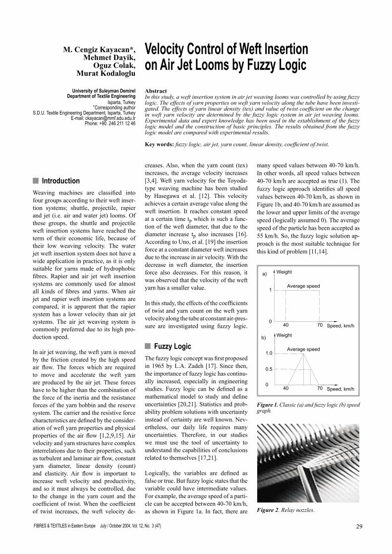
Logically, the variables are defined as false or true. But fuzzy logic states that the variable could have intermediate values. For example, the average speed of a parti-cle can be accepted between 40-70 km/h, as shown in Figure 1a. In fact, there are
many speed values between 40-70 km/h. In other words, all speed values between 40-70 km/h are accepted as true (1). The fuzzy logic approach identifies all speed values between 40-70 km/h, as shown in Figure 1b, and 40-70 km/h are assumed as the lower and upper limits of the average speed (logically assumed 0). The average speed of the particle has been accepted as 55 km/h. So, the fuzzy logic solution ap-proach is the most suitable technique for this kind of problem [11,14].
Abstract In this study, a weft insertion system in air jet weaving looms was controlled by using fuzzy logic. The effects of yarn properties on weft yarn velocity along the tube have been investi-gated. The effects of yarn linear density (tex) and value of twist coefficient on the change in weft yarn velocity are determined by the fuzzy logic system in air jet weaving looms. Experimental data and expert knowledge has been used in the establishment of the fuzzy logic model and the construction of basic principles. The results obtained from the fuzzy logic model are compared with experimental results.
Key words: fuzzy logic, air jet, yarn count, linear density, coefficient of twist.
Figure 1. Classic (a) and fuzzy logic (b) speed graph.
Weight
Weight
Average speed
Average speed
40 70 Speed, km/h0
1
a)
0
1.0
0.5
40 70 Speed, km/h
b)
Figure 2. Relay nozzles.
FIBRES & TEXTILES in Eastern Europe July / October 2004, Vol. 12, No. 3 (47)30 31FIBRES & TEXTILES in Eastern Europe July / October 2004, Vol. 12, No. 3 (47)
Uncertainty conditions in fuzzy logic are determined by pre-defined membership functions. If the most approximate ele-ment of the results is defined as 1, it can be understood that the other elements are between 0 and 1 and they are changing continuously. The value of every element with the variation between 0 and 1 are called membership degrees, and the vari-ation in a subset is called membership function [17]. After that, the definition of the fuzzy logic rule base is implemented by using either Suggeno or Mamdani’s method.
After a solution of the implemented fuzzy logic system has been obtained by using the selected method, the solu-tion is defuzzified. The defuzzification
method is called as the inverse operation of fuzzification. There are seven follow-ing defuzzification methods: Centroid, Bisector, Moment, LOM (Largest of maximum), SOM (Smallest of maxi-mum), MOM (Mean of maximum) and COG (Centre of gravity) [17,21].
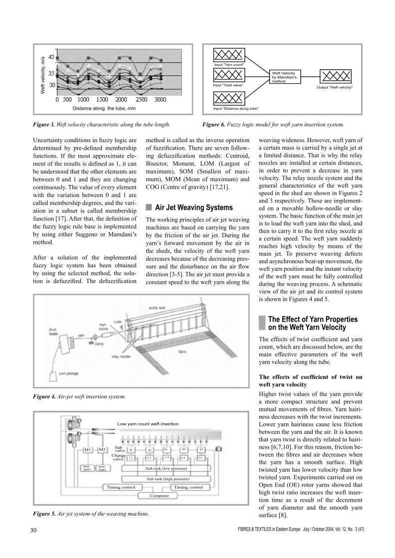
n Air Jet Weaving Systems The working principles of air jet weaving machines are based on carrying the yarn by the friction of the air jet. During the yarn’s forward movement by the air in the sheds, the velocity of the weft yarn decreases because of the decreasing pres-sure and the disturbance on the air flow direction [3-5]. The air jet must provide a constant speed to the weft yarn along the
weaving wideness. However, weft yarn of a certain mass is carried by a single jet at a limited distance. That is why the relay nozzles are installed at certain distances, in order to prevent a decrease in yarn velocity. The relay nozzle system and the general characteristics of the weft yarn speed in the shed are shown in Figures 2 and 3 respectively. These are implement-ed on a movable hollow-needle or slay system. The basic function of the main jet is to load the weft yarn into the shed, and then to carry it to the first relay nozzle at a certain speed. The weft yarn suddenly reaches high velocity by means of the main jet. To preserve weaving defects and asynchronous beat-up movement, the weft yarn position and the instant velocity of the weft yarn must be fully controlled during the weaving process. A schematic view of the air jet and its control system is shown in Figures 4 and 5.
n The Effect of Yarn Properties on the Weft Yarn Velocity
The effects of twist coefficient and yarn count, which are discussed below, are the main effective parameters of the weft yarn velocity along the tube.
The effects of coefficient of twist on weft yarn velocity Higher twist values of the yarn provide a more compact structure and prevent mutual movements of fibres. Yarn hairi-ness decreases with the twist increments. Lower yarn hairiness cause less friction between the yarn and the air. It is known that yarn twist is directly related to hairi-ness [6,7,10]. For this reason, friction be-tween the fibres and air decreases when the yarn has a smooth surface. High twisted yarn has lower velocity than low twisted yarn. Experiments carried out on Open End (OE) rotor yarns showed that high twist ratio increases the weft inser-tion time as a result of the decrement of yarn diameter and the smooth yarn surface [8].
Figure 3. Weft velocity characteristic along the tube length.
Figure 4. Air-jet weft insertion system.
Figure 5. Air jet system of the weaving machine.
Figure 6. Fuzzy logic model for weft yarn insertion system.
FIBRES & TEXTILES in Eastern Europe July / October 2004, Vol. 12, No. 3 (47)30 31FIBRES & TEXTILES in Eastern Europe July / October 2004, Vol. 12, No. 3 (47)
The effect of yarn count (linear den-sity) on weft velocity Different yarn counts have different lin-ear densities, and so the velocity of a thin weft yarn is much higher than the veloc-ity of the thick weft yarn, which also has low starting velocity as a result of the in-verse relationship between velocity and mass. During weft insertion, the velocity of thick weft yarns reaches the maximum at the end of the shed line, because of its inertia. Since the inertia of thin yarns is lower than that of thick yarns, the veloc-ity at the end of shed of thin yarn is lower than that of the thick yarn. However, the effect of inertia is not as important as the effect of mass. Therefore, thin yarns have higher average velocity all along the length of the weft insertion line [8,18].
n Determination of Weft Yarn Velocity by Fuzzy Logic
The aim of this work was to check whether the fuzzy logic system can be used for predicting the weft yarn inser-tion velocity. To achieve this aim, it was necessary to compare the results obtained by fuzzy logic with those from real meas-urements.
The yarn count and the coefficient of twist were selected as input variables, whereas yarn velocity was the output variable. The fuzzy model of this prob-
lem is given in Figure 6. Real values of weft velocity for comparison with those obtained by fuzzy logic have been taken from the experimental study results of Adanur [1]. These were carried out on the basis of the following parameters: § jet type - NCSU No 1⁄2 § weft insertion pressure - 0-689 kPa § weft insertion cycle - 500 weft/min § weft feed type - drum, loop § mean humidity - 45-80% § temperature - 15-30°C
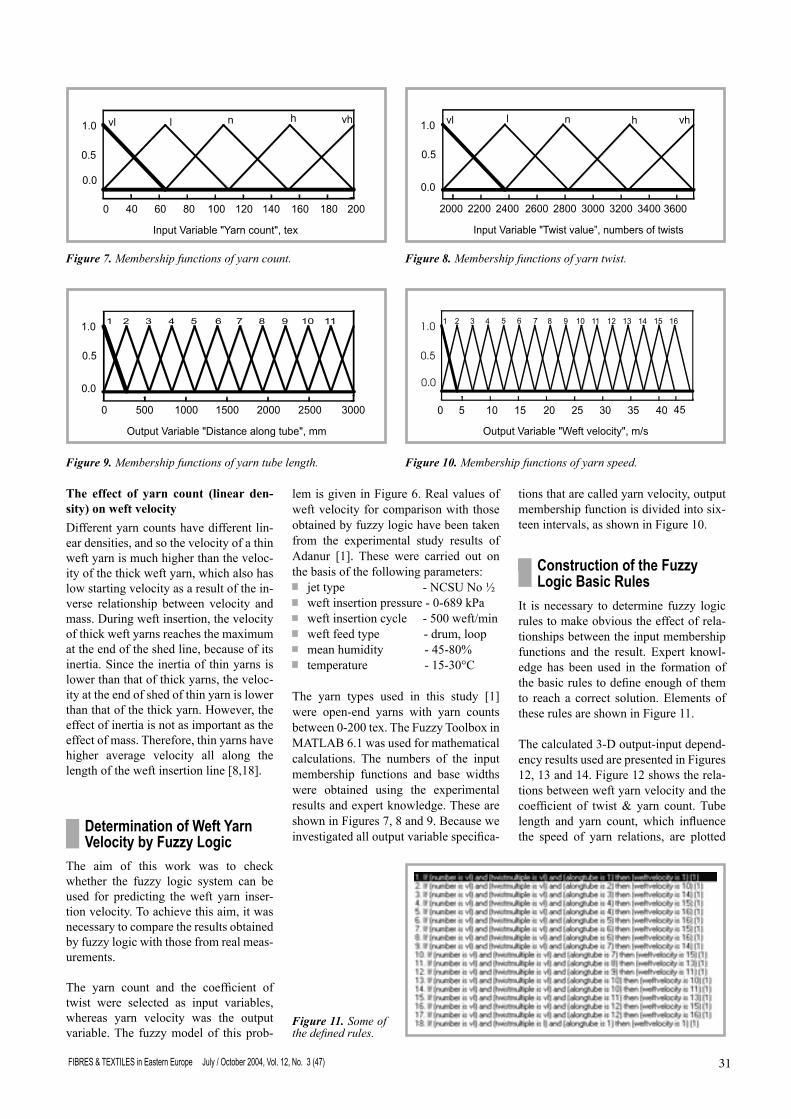
The yarn types used in this study [1] were open-end yarns with yarn counts between 0-200 tex. The Fuzzy Toolbox in MATLAB 6.1 was used for mathematical calculations. The numbers of the input membership functions and base widths were obtained using the experimental results and expert knowledge. These are shown in Figures 7, 8 and 9. Because we investigated all output variable specifica-
tions that are called yarn velocity, output membership function is divided into six-teen intervals, as shown in Figure 10.
n Construction of the Fuzzy Logic Basic Rules
It is necessary to determine fuzzy logic rules to make obvious the effect of rela-tionships between the input membership functions and the result. Expert knowl-edge has been used in the formation of the basic rules to define enough of them to reach a correct solution. Elements of these rules are shown in Figure 11.
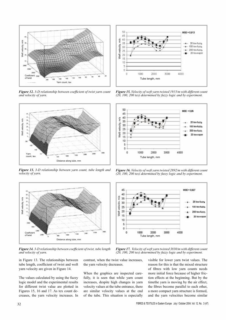
The calculated 3-D output-input depend-ency results used are presented in Figures 12, 13 and 14. Figure 12 shows the rela-tions between weft yarn velocity and the coefficient of twist & yarn count. Tube length and yarn count, which influence the speed of yarn relations, are plotted
Figure 9. Membership functions of yarn tube length. Figure 10. Membership functions of yarn speed.
Figure 7. Membership functions of yarn count. Figure 8. Membership functions of yarn twist.
Figure 11. Some of the defined rules.
FIBRES & TEXTILES in Eastern Europe July / October 2004, Vol. 12, No. 3 (47)32 33FIBRES & TEXTILES in Eastern Europe July / October 2004, Vol. 12, No. 3 (47)
in Figure 13. The relationships between tube length, coefficient of twist and weft yarn velocity are given in Figure 14.
The values calculated by using the fuzzy logic model and the experimental results for different twist value are plotted in Figures 15, 16 and 17. As tex count de-creases, the yarn velocity increases. In
contrast, when the twist value increases, the yarn velocity decreases.
When the graphics are inspected care-fully, it is seen that while yarn count increases, despite high changes in yarn velocity values at the tube entrance, there are similar velocity values at the end of the tube. This situation is especially
visible for lower yarn twist values. The reason for this is that the mixed structure of fibres with low yarn counts needs more initial force because of higher fric-tion effects at the beginning. But by the timethe yarn is moving by the air effect, the fibres become parallel to each other, a more compact yarn structure is formed, and the yarn velocities become similar
Figure 12. 3-D relationship between coefficient of twist yarn count and velocity of yarn.
Figure 13. 3-D relationship between yarn count, tube length and velocity of yarn.
Distance along tube, mm
Wef
tvel
ocity
,m/s
Coeficientof twist
Figure 14. 3-D relationship between coefficient of twist, tube length and velocity of yarn.
Tube length, mm
Wef
tvel
ocity
,m/s
Figure 15. Velocity of weft yarn twisted 1915/m with different count (20, 100, 200 tex) determined by fuzzy logic and by experiment.
Tube length, mm
Wef
tvel
ocity
,m/s
Figure 16. Velocity of weft yarn twisted 2892/m with different count (20, 100, 200 tex) determined by fuzzy logic and by experiment.
Wef
tvel
ocity
,m/s
Tube length, mm
Figure 17. Velocity of weft yarn twisted 3830/m with different count (20, 100, 200 tex) determined by fuzzy logic and by experiment.
Distance along tube, mm
Yarncount, tex
Wef
tvel
ocity
,m/s
FIBRES & TEXTILES in Eastern Europe July / October 2004, Vol. 12, No. 3 (47)32 33FIBRES & TEXTILES in Eastern Europe July / October 2004, Vol. 12, No. 3 (47)
to each other. The comparison of result obtained by using the fuzzy logic model and from experimental studies are given in Figures 15, 16 and 17.
n Conclusions In this study, the effect of yarn param-eters on the yarn velocity along the weft insertion tube was investigated. The effect of the twist coefficient of weft yarn on weft yarn velocity at different yarn linear densities was determined by using fuzzy logic. When the calculated and experimental results of the weft yarn insertion are compared, the following conclusions can be drawn.
Since a high twist coefficient makes the yarn more compact and smoother, it reduces the yarn velocity and increases the insertion time. Increase in yarn count increases the velocity of the weft yarn led through the tube. The yarn speed can be easily determined in dependence on twist coefficient and yarn count by fuzzy logic. It is practically possible to obtain approaches that will give positive results with yarn velocity optimisation in a more economical way, instead of the method of experimental study.
Acknowledgement This study is supported by the Prime Ministry State Planning Organisation (TR), Project No: DPT 2000 K 120430 and SDU Af 238.
References 1. Adanur, S. and Mohamed, M. H., 1992,
Analysis of Yarn Motion in Single-nozzle Air-Jet Filling Insertion, Part II: Experimen-tal Validation of the Theoretical Models and Statistical Analysis, Journal of the Textile Institute, Vol. 83, No. 1 pp. 56-68.
2. Adanur, S., Walker, R. P., Broughton,R. M. and Beale, D. 1994, Weaving Techno-logy - What Next?, Melliand Textilberich-te, English/German, Vol. 75, No. 4, April, pp. 255-263.
3. Adanur, S., and Mohamed, M. H., 2001, Weft Insertion on Air-jet Looms: Velocity Measurement and Influence of Yarn Structure Part II Effects of System Para-meters and Yarn Structure, Journal Textile Inst. No 2, 1988 systems, 121 (73-93).
4. Adanur, S. and Mohamed, M. H., 1992, Analysis of Yarn Motion in Single-nozzle Air-Jet Filling Insertion, Part I: Theoretical Models for Yarn Motion, Journal of the Te-xtile Institute, Vol. 83, No 1, pp. 54-55.
5. Adanur, S., 1989, Dynamic Analysis of Single Nozzle Air-jet Filling Insertion, Ph.D. Thesis, NCSU.
6. Adanur, S., 1995, Effects of Fabric Struc-tural Parameters on Fabric Modulus, Mel-liand Textilberichte, Vol. 76, No. 6, June (German/English), pp. 396-399.
7. Adanur, S., and Bahtiyarov, S., 1996, Analysis of Air Flow in Single Nozzle Air-Jet Filling Insertion: Corrugated Channel Model, Textile Research Journal, 66(6), pp. 401-406.
8. Adanur,S. and Mohamed, M. H., 1991, Analysis of Yarn Tension in Air-Jet Filling Insertion, Textile Research Journal, Vol.61, No. 5, pp. 253-258.
9. Bayhan, M., Kodaloglu, M., Cengiz, Y. and Kaplan, S., 2002, Drum ve Loop Sistemlerinde Atki Hareketinin Dinamik Modellenmesi ve Hizin Bulanik Mantikla Kontrolu, Tekstil Maraton Dergisi, Mart-Nisan. pp. 63-69.
10. Batra, S. K., Ghosh, T. K. and Zeidman, M., 1987, Dynamic Analysis of Yarn in Ring Spinning: An Integrated Approach, NCSU, March, pp. 256-262.
11. Branco, P. J., and Dente, J. A., 2001, “Fuz-zy Systems Modelling in Practice”, Fuzzy Sets and System Vol. 121, pp: 73-93.
12. Hasegawa J., et al., 1981, A Study of Weft Insertion System on Air Jet Loom, Paper presented at ASME Textile Engineering conference, Raleigh, NC, pp. 358-45.
13. Kayacan, M. C., Dayık, M., 2001, Bulanık Mantık Yardımıyla Bornoz Beden Ölçü-lerinin Tespiti, Tekstil Maraton. Temmuz-Ağustos, pp. 65-72.
14. Kissling U., 1985, Experimental and Theoretical Analysis of Weft Insertion by Air-jet, Melliand Textilberichte. February, pp. 145-152.
15. Salama, M. M., 1984, Mechanics of Air Jet Filling Insertion, PhD Thesis, UMI.
16. Salama, M., Adanur, S., and Mohamed, M.H., 1987, Mechanics of a Single Noz-zle Air-Jet Filling Insertion System, Part III: Yarn Insertion through Tubes, Textile Research Journal, Vol. 57, No.1, January, pp. 44-54.
17. Şen, Z. 1999, Mühendislikte Bulanık (Fuzzy) Modelleme İlkeleri, Ders Notları, İstanbul.
18. Vangheluwe, L., Puissant, P., Kiekens, P., 1997, Combination of Fuzzy Feedback Lo-ops and Feedforward Adaptive Systems for Weft Insertion Control in Air-Jet We-aving; Proceedings of the 3rd International Conference on Design to Manufacture in Modern Industry, University of Maribor, Fa-culty of Mechanical Engineering, suppor-ted by the Slovenian Ministry of Science and Technology, Portoroz, Slovenia, 8-9 September, pp. 471-478.
19. Uno, M., et al., 1972, A Study on an Air Jet Loom with Substreams Added. Part 5: Analogous Experiment of Flow, J. Te-xtile Machinery Soc., Japan, Vol. 18, pp. 5-16.
20. Zadeh, L. A, 1965, Fuzzy Sets, Informa-tion and Control Vol. 8, pp. 338-353.
21. Zadeh, L. A., l978, Fuzzy Sets As A Basis For A Theory Of Possibility, pp 3-10.
22.http://www.sulzertextil.com/solutions/weaving/i_airjet.htm
Received 10.03.2003 Reviewed 12.08.2003