vehicle to vehicle communications -...
TRANSCRIPT

Vehicle to Vehicle Communications
A Wireless System to Promote Safety and Traffic Control
Shawn Baker Matt Denault
Michael O’Keefe
EEL 6908, Fall Dec 12, 2014

Vehicle to Vehicle Communications
ii
Table of Contents
Vehicle to Vehicle Communications ................................................................................. 1 Goals ................................................................................................................................................... 1
Technology Background ................................................................................................... 3
The Market ...................................................................................................................... 5
Safety ........................................................................................................................... 5
Buyers .......................................................................................................................... 6
System Requirements ....................................................................................................... 8
Simulation ..................................................................................................................... 11
Introduction ............................................................................................................... 11
Key Objectives ........................................................................................................... 11
Simulation Description ............................................................................................... 12 Top Level Models - Adaptive_CC_World and Blindspot_World ......................................................... 12 CarDynamics Model .......................................................................................................................... 13 DetectionSys Model ........................................................................................................................... 14 Determine Closest Vehicle Module ..................................................................................................... 15 If Block - Adaptive Cruise Control ...................................................................................................... 15 If Block - Blindspot Warning .............................................................................................................. 16
Hardware Requirements ................................................................................................. 17
Transceiver setup ........................................................................................................ 17
Vehicle Hardware Requirements ................................................................................. 18
Project Outcomes ........................................................................................................... 20
Conclusion .................................................................................................................... 20

Vehicle to Vehicle Communications
1
Vehicle to Vehicle Communications
The vehicle-to-vehicle (V2V) communications suite is still in its initial stages of design. However, the idea has been under test in varying capacities for more than a decade. The goal is to develop a two-way communications pallet that will transmit and receive position and route data in order to reduce traffic accidents. The system will be a narrow band, propagation type system at 5.9 GHz. The Federal Communications Commission (FCC) has already made the spectrum allocation. The system will also incorporate a differential global position system (DGPS) that most vehicles already have. The goal will be to transmit and receive within a range of 1 kilometer.
Goals n Design a system that senses the location of other vehicles on the roadway;
n Design a system that wirelessly communicates with other vehicles and transmits and receives data (e.g. vehicle speed);

Vehicle to Vehicle Communications
2
n Design a system that receives and interprets the roadway characteristics (e.g. roadway grade and slope, wetness conditions, turn direction and radius);
n Simulate demands of the designed system on the current vehicle system to ensure vehicle performance is not compromised; and
n Determine if an automated system is financially feasible for a modern economy vehicle.
The system will be simulated using Simulink by Matlab. The simulation will implement two car behaviors, adaptive cruise control, and blindspot monitoring. The models will be self contained and output to a VRML word in order to show the position of the vehicle and current safety functions.
The motivator for this system is safety. Currently traffic accidents cause about 1.2 million deaths per year worldwide. There are also another 50 million injuries. A goal of this system will be to reduce those numbers by 25%, making it a viable product for major manufacturers of cars.

Vehicle to Vehicle Communications
3
Technology Background Vehicle to vehicle (V2V) communications systems have a long history with the Intelligent Transportation Society of America (ITS). Intelligent transportation systems were first researched as part of the Automated Highway System (AHS) in the 1990s. This system used magnetized steel spikes along the highway to determine the speed of the vehicle, the position of the vehicle in the lane, and to signal information to the driver. The first test of the AHS was done on I-15 in California in 1997 and was considered a success. However, the scale of implementing such a system into the existing highway structure would have outweighed the benefits. AHS required tight control over the lanes that the system used and did not have systems to dynamically react to situations on the highways.
Platoon Demonstration of AHS system
After AHS showed a promising future as to how an intelligent highway system may improve highway congestion, the Transportation Equality Act for the 21st Century (TEA-21) allowed the United States Department of Transportation to form the Intelligent Vehicle Initiative (IVI) as part of the Intelligent Transportation Systems (ITS) program. IVI had two objectives: To prevent driver distraction and to facilitate accelerated deployment of crash avoidance systems. The 2005 IVI Final Report found that majority of collisions were due to

Vehicle to Vehicle Communications
4
rear end collisions, roadway departure, lane changes, and collisions at intersections. Adaptive cruise control and lane departure warning systems were two of the many technologies developed in five years from the IVI.
Blind Spot Monitoring developed as part of IVI
Today's V2V technology is part of the Vehicle Infrastructure Integration (VII) Initiative. This initiative is to fuse the developments of IVI to modern telecommunications infrastructure. This would enable local traffic departments to have a better understanding of traffic conditions as well as improved safety for commuters. As part of VII, the Federal Communications Commission allocated a small frequency spectrum at 5.9 GHz for use in V2V applications. VII is a fusion of position information, vehicle telemetry and ad-hoc communications. The VII has shown in Proof of Concept trials that the system is ready for further adoption and shows that the roadways can be safer.
Vehicle to Vehicle Communications
5
The Market
Safety
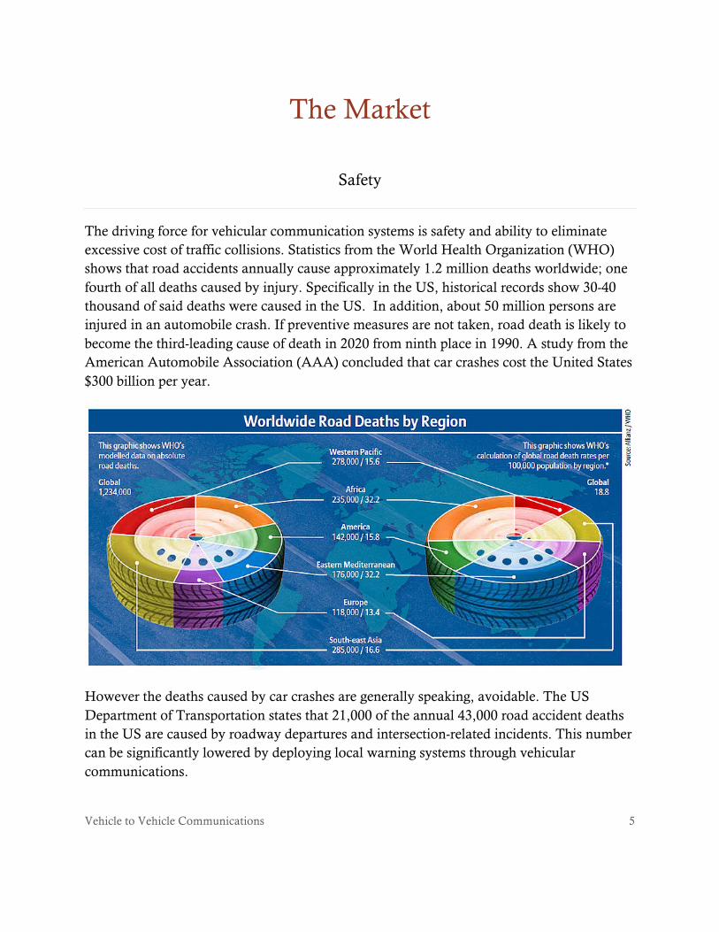
The driving force for vehicular communication systems is safety and ability to eliminate excessive cost of traffic collisions. Statistics from the World Health Organization (WHO) shows that road accidents annually cause approximately 1.2 million deaths worldwide; one fourth of all deaths caused by injury. Specifically in the US, historical records show 30-40 thousand of said deaths were caused in the US. In addition, about 50 million persons are injured in an automobile crash. If preventive measures are not taken, road death is likely to become the third-leading cause of death in 2020 from ninth place in 1990. A study from the American Automobile Association (AAA) concluded that car crashes cost the United States $300 billion per year.
However the deaths caused by car crashes are generally speaking, avoidable. The US Department of Transportation states that 21,000 of the annual 43,000 road accident deaths in the US are caused by roadway departures and intersection-related incidents. This number can be significantly lowered by deploying local warning systems through vehicular communications.

Vehicle to Vehicle Communications
6
V2V communications will enable active safety systems that can assist drivers in preventing 76 percent of the crashes on the roadway, thereby reducing fatalities and injuries that occur each year. Along with a drastic increase in safety of motor vehicle operators, vehicle communications systems can assist in avoiding congestion and premium route selection based on real time processing of data. The return will include savings of both time and fuel and has an obvious economic advantage.
Buyers
In order for a project to be implemented, there must be a market. The automobile market is increasing drastically. North American and Asian car sales are leading the way to a market that will boast 70 million vehicle sales in 2014.
According to the Wall Street Journal, the following are the largest automobile manufacturers in the world:
n Renault
n Suzuki
0
10
20
30
40
50
60
70
80
1990-1999 2000-2010 2011 2012 2013 2014
Number of Cards Sold Worlwide from 1900 to 2014
Car Sales in Millions

Vehicle to Vehicle Communications
7
n Peugeot
n Honda
n Nissan
n Ford
n Hyundai
n Volkswagen
n General Motors
n Toyota
The automotive industry spends nearly $100 billion globally on research and development of new technology, $18 billion of which is in the US alone. Only a fraction of industry spending would outfit automaker’s entire fleet with V2V communications.
Vehicle to Vehicle Communications
8
System Requirements
Useful implementation of a VSV system must ensure that information to and from the system is timely, reliable, and be in a standard format among all vehicles. The V2V system envisioned by the US Department of Transportation proposes a standardized dedicated short range communication (DSRC) network to transmit and receive vehicle-to-vehicle communications. The transmissions would be broadcast across the IEEE 802.11p wireless layer. The US Department of Transportation’s proposition to use DSRC may lie in the network’s suitability for local-area, low-latency network connectivity. The DSRC is also adequate to support vehicle-to-vehicle messaging as well as messaging between vehicles and roadside access points.
A capable V2V communication system should provide for interoperability between systems, meet reliable data distribution requirements, establish suitable security measures, and have sufficient system monitoring requirements. If any of these areas is compromised, the V2V communication system may fail and individuals may be injured or killed and accidents may occur, which may result in traffic congestion.
Interoperability
Creating a network with interoperability is a key aspect to the success of a V2V system. If vehicles do not transmit in the same format, then it may not be possible for a vehicle receiving that broadcast information to understand what is being received. Interoperability may be solved by ensuring all vehicles on a network are broadcasting on the frequency band. It should be noted, as V2V communication becomes more widespread around the world, different bands may be implemented in different regions. Therefore, a vehicle with a V2V system installed should be prepared to change its frequency band to the frequency band that is utilized in a particular region the vehicle is in or travels to.
Reliable Connections and Data Distribution
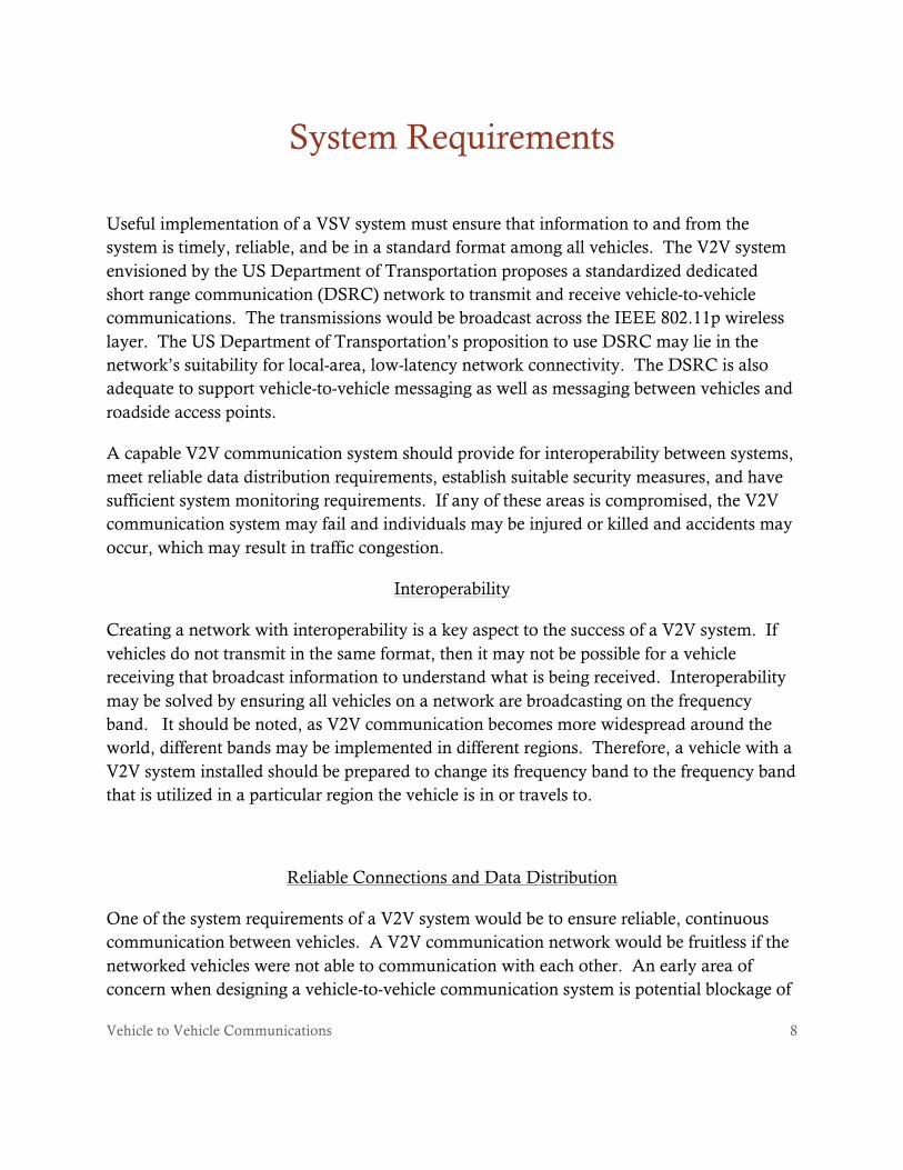
One of the system requirements of a V2V system would be to ensure reliable, continuous communication between vehicles. A V2V communication network would be fruitless if the networked vehicles were not able to communication with each other. An early area of concern when designing a vehicle-to-vehicle communication system is potential blockage of
Vehicle to Vehicle Communications
9
signal by either other vehicles or natural obstacles. One such example was presented by the National Highway Traffic Safety Administration (NHTSA).
In this example, car A is followed by truck B, which is followed by car C. If the spacing between these vehicles is small enough, there is a potential issue that car C may not receive the signal transmitted by car A due to the blockage of truck B. The reason for this is due to the characteristics of 5.9 GHz DSRC waves. These waves do not easily travel through solid objects and are heavily reliant on line-of-sight communication. A potential workaround to this issue may be to create a “hive mind” type of network where the DSRC signal is retransmitted by truck B so that car C receives the, otherwise, blocked signal.
Security Protections
Any implemented V2V communication system must offer some sort of system security protections in order to insure that the system is not attacked by a third party that negatively impacts the system’s reliability and performance. The Intelligent Transportation Systems division of the US Department of Transportation in a report from 2011 wrote that attackers on a V2V communication system would have two goals: 1) cause users to make poor driving decisions that would result in accidents, traffic congestion, and the rerouting of drivers; and 2) lower user faith in the V2V communication system. Any attack on the V2V system would either need to be a wirelessly transmitted signal within the affected vehicle’s transmission radius or a physical alteration of a particular vehicle’s system. Both methods would likely result in the system providing false messages to either the altered vehicle or those vehicles within the transmission radius of the affected vehicle, since vehicles within the transmission radius may receive false transmissions from the affected vehicle.
Several methods may be available to ensure security of the V2V system. For example, the communication device may be located within the passenger compartment of the vehicle in order to shield third parties from access to the hardware system. Similarly, an encryption code may be implemented to prevent foreign signals from interfering with the vehicle communication system. If the vehicle’s communication computer receives a signal that is not properly encrypted, the system can disregard the information.

Vehicle to Vehicle Communications
10
Monitoring Requirements
The monitoring system monitors the core systems of the V2V communication network in each vehicle to ensure that each individual system is performing adequately. The system will periodically perform a scan to ensure performance benchmarks are met along with a virus scan to determine if any security risks are present. Additionally, the monitoring system will perform network port monitoring and allow capability for patch downloads. Should any risks or deficiencies be detected, the system will take measures to mitigate those risks or deficiencies.
The monitoring system will also monitor environmental conditions, such as temperature and humidity levels. Should temperature be outside of an acceptable range, system performance may be compromised. Mitigation actions may include system cooling or heating devices, dehumidifiers, and/or power backup systems.
The monitoring system will also keep a record of the system performance and communications for professionals that run diagnostics on the system to determine if the system is operating within a reasonable spectrum of performance.

Vehicle to Vehicle Communications
11
Simulation Introduction
The vehicle traffic and communications simulation was created using Simulink from Mathworks. Simulink allows simulations to be quickly built and tested in an graphical programming environment. Simulink enables simulations to be built in a modular manner that allows subsystems to be easily replaced as models are more fully developed. Basic functionality can be replaced with more advanced algorithms as a simulation develops to more accurately reflect the response of the system simulated.
This simulation requires the Simulink 3D Animation module to show animations of the system running in real time using a world described in Virtual Reality Modeling Language, or VRML. To run the Simulink files, the directory that contains the files should be added to Matlab’s path.
Simulink model files can be found at http://v2vtech.weebly.com/project-outcomes.html.
Key Objectives
• The simulation shall implement two car behaviors: An adaptive cruise control system and a blindspot monitoring system based on position communication.
• Models that describe the motion and behaviors of the vehicle shall be self contained so that the same model can be reused for each vehicle in the simulation.
• The models shall minimize the use of custom Matlab functions in favor of Simulink blocks.
• Simulation shall output to a VRML world that shows the position of the vehicles and the current state of safety functions.
Vehicle to Vehicle Communications
12
Simulation Description
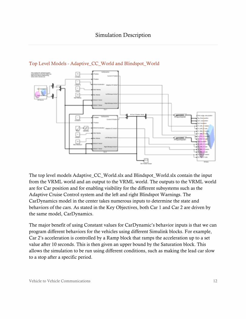
Top Level Models - Adaptive_CC_World and Blindspot_World
The top level models Adaptive_CC_World.slx and Blindspot_World.slx contain the input from the VRML world and an output to the VRML world. The outputs to the VRML world are for Car position and for enabling visibility for the different subsystems such as the Adaptive Cruise Control system and the left and right Blindspot Warnings. The CarDynamics model in the center takes numerous inputs to determine the state and behaviors of the cars. As stated in the Key Objectives, both Car 1 and Car 2 are driven by the same model, CarDynamics.
The major benefit of using Constant values for CarDynamic’s behavior inputs is that we can program different behaviors for the vehicles using different Simulink blocks. For example, Car 2’s acceleration is controlled by a Ramp block that ramps the acceleration up to a set value after 10 seconds. This is then given an upper bound by the Saturation block. This allows the simulation to be run using different conditions, such as making the lead car slow to a stop after a specific period.

Vehicle to Vehicle Communications
13
CarDynamics Model
The CarDynamics model calculates the position of the car for each simulation cycle by using Integration blocks. The DetectionSys model calculates other vehicle positions and determines if the Adaptive Cruise Control system or the Blindspot Warning system should be activated. If the Adaptive Cruise Control system is activated, it outputs a proportional velocity value that starts to limit the vehicle speed.
The Velocity Limiter function breaks one of the key objectives. Simulink does not have any blocks that allow dynamic value limiting, but for a good reason. The Saturation block is designed to run as quickly as possible using the upper and lower bounds as the limit. In order to get a dynamic velocity limit output, we need to use a custom Matlab function. The code below is used in the Velocity Limiter.

Vehicle to Vehicle Communications
14
DetectionSys Model
The DetectionSys model implements another module to determine the closest vehicle. This information is then sent to an If block to determine if the Adaptive Cruise Control system should be activated or if the Blindspot Warning system should be activated. Current Velocity is used to dynamically change the detection distance based on velocity. The system currently is set up to look 20 units of distance ahead of the vehicles.

Vehicle to Vehicle Communications
15
Determine Closest Vehicle Module
The Determine Closest Vehicle module converts the X and Y coordinates used by the VR Simulation system to a polar coordinate system. This is so that the closest target can be determined and the location information is sent out to the If block in DetectionSys. Since the Vehicle Vector inputs include the data for the vehicle itself, we subtract the current X and Y coordinates of that vehicle to set them to zero. The Find Nonzero Elements block removes them and passes them on to be converted to polar coordinates.
One important implementation detail is the use of the Selector block to limit the output to a single value. This was done to satisfy the If block. The If block can only take a single value while the entire Determine Closest Vehicle module can handle variable length values.
If Block - Adaptive Cruise Control
The first If block determines if the Adaptive Cruise Control system should be activated and changes the Velocity Fraction value appropriately. The switch block is to prevent the velocity fraction from becoming a negative value, leading to unintended acceleration. The

Vehicle to Vehicle Communications
16
Relational Operator value sets a boolean TRUE or FALSE.
If Block - Blindspot Warning
The second If block determines which blindspot monitor to activate, left or right. A logical NOT is used to prevent the second side from being activated at the same time.

Vehicle to Vehicle Communications
17
Hardware Requirements
Hardware requirements for a V2V system to be effective can be broken into two sets of components. The first component set is the device, which will act as a transmitter of accurate and basic data messages for safety, routing, etc. Second are the components that will allow the system to receive and interpret the same data from a separate entity.
Transceiver setup
To produce a basic safety or routing message, the device will be required to know its own position. Existing GPS devices in new vehicle can be tapped into for this data. The system will require a data processing unit that can use the location from an external GPS, combine it with data from onboard vehicle sensors providing speed, acceleration, and heading. Once this data string has been generated, a device will be needed to transmit this message wirelessly to a separate entity. Throughout this process, there needs to be a security component that can generate security credential certificates. This allows the receiving entity to verify the transmitted message is a legitimate one. To receive and decode the transmitted information, the device will need to have a data processing unit for decoding. GPS information will also be required to interpret information relative to the receiving entity. Lastly, the device needs to operate critical advisories and immanent threat alerts. Options for these are heads up display, properly placed LEDs, and audible noises.
In order for total interoperability, there needs to be a setup internal to the vehicle, but there also needs to be road side equipment units to help with security management and system updates. Furthermore, equipment could be added to traffic lights, signs, crosswalks, and other pieces of existing infrastructure.

Vehicle to Vehicle Communications
18
Vehicle Hardware Requirements
The figure provided is from Terranautix Co. It illustrates a system level view of a V2V communication system based off of the dedicated short-range communication system.
At a minimum the onboard V2V system proposed would require two DSRC radios along with a GPS receiver and a CPU of some kind. The NHTSA foresees the potential for these systems to be integrated into an existing electronic control unit during vehicle production. There are multiple examples of existing DSRC radios on the market. An example is the RSE650 DSRC by Q-free. Designed for parking lot management and toll both applications, this system would be a few minor changes away from being a near 100% solution for a V2V system. Below are the system specifications.

Vehicle to Vehicle Communications
19
Max vehicle speed: >200km/h Operating frequency: 5.7975, 5.8025, 5.8075 and 5.8125GHz Typical communication zone: 3 x 4m (W x L) @ 6m height, 45° installation angle Downlink bit rate: 500kbps Uplink bit rate: 250kbps Sub-‐carrier frequencies: 1.5MHz (Profile 0) and 2.0MHz (Profile 1) RTTT Profiles: EN13372 Set A and Set B Receiver sensitivity: Better than -‐103dBm (BER <10-‐6) Antenna polarization: Left-‐hand circular Radiated power (EIRP): 33dBm, 2W max (SW Adjustable) Network for data communication Ethernet 100BaseTX Power supply: Power over Ethernet Power consumption: ~ 12W Connectors: Snap on, no tools required Operating temperature: -‐33°C to +55°C IP grade: IP65 Tested for wind speeds up to: 100km/h Classification of environmental parameters:
IEC60721 3-‐4 Class G1 (Parameters 4K4/4K2a/4Z5/4M6/4Z8/4S3/4Z10/4B1/4C2)
MTBF: >50,000h
A minor condition for system feasibility will be to take a device like the one listed above and make it automotive grade. This will require more stringent environmental conditions and a higher quality rating with regards to defects in parts per million. Examples of the environment conditions that will need to be endured by the device are temperature, vibrations, and electro-magnetic interference. In addition, there should be an option developed for aftermarket install.

Vehicle to Vehicle Communications
20
Project Outcomes The Simulink simulation shows that a vehicle communication system can be used to increase the safety of drivers on busy roadways. A V2V communications network shows that sensor functionality can be duplicated for added redundancy in vehicles without adding substantial complexity to the detection and position algorithms used. The simulation environment is an ideal method of simulating busy traffic conditions to determine the impact of how a V2V Communications system can alleviate congested traffic in heavily trafficked roads. Videos of the system results can be found at http://v2vtech.weebly.com/project-outcomes.html.
Conclusion
The vehicle-to-vehicle communication system is not a new concept. There have been varying levels of the system under test since the early 1990s. The market for a product of this nature is massive. Throughout the world, there are millions of people injured or killed in automobile accidents. This fact combined with an industry that is willing to spend in excess of $100 billion on research and development of new technology, sets the stage for a product solution. Because of the amount of time V2V has been in development, a lot of system requirements are already mapped. IEEE 802.11p will be the wireless layer for broadcast. Additional system level concerns are; interoperability with regards to different entities, existing systems, and road side equipment; security of the systems messaging to include erroneous message detection and error analysis; and reliability with regards to dependability of information along with two-way connection. The system was simulated using Simulink by Matlab. VRML was used to display a simulation model boasting self contained systems that can accurately implement adaptive cruise control and blind spot monitoring. The system will help to facilitate follow on simulations to increase its capabilities further. The hardware required to make the simulation a reality is close to ready right now. Most of the system can operate using existing vehicle equipment, and the rest can be achieved using CPUs combined with a DSRC device. There are existing DSRC devices that could be slightly tweaked to achieve the required capabilities of the vehicle system. Road side equipment infrastructure is already existing as well. An example would be the devices that monitor toll roads.

Vehicle to Vehicle Communications
21
Overall, this study has shown that the technology for V2V technology is on the cusp. There are minor hardware and software changes that need to be made to make this an every day, every vehicle system, but this simulation should act as a proof of concept for follow on study.

Vehicle to Vehicle Communications
22
Bibliography
1-‐ US DoT, Office of the Assistant Secretary of Research and Technology, June 26, 2014, http://www.its.dot.gov/research/v2v.htm#sthash.tkdSKTai.dpuf
2-‐ M. Peden, Richard Scurfield, D. Sleet, D. Mohan, A. A. Hyder, E. Jarawan, and C. Mathers. "World report on road traffic injury prevention" (PDF). World Health Organization.
3-‐"Crashes Vs. Congestion -‐-‐ What's the Cost to Society?" (PDF). American Automobile Association. November 30, 2011
4-‐ "Vehicle Infrastructure Integration (VII)". its.dot.gov. February 2, 2011
6-‐ “International Car Sales”, Worldwide Statista Report, 1990-‐2014 http://www.statista.com/statistics/200002/international-‐car-‐sales-‐since-‐1990/
7-‐ Douglas A. McIntyre, Thomas C. Frohlich and Alexander E.M, “The Worlds Largest Automakers”, September 13, 2013, Wall Street Journal. http://247wallst.com/specialreport/2013/09/13/the-‐worlds-‐largest-‐automakers/3/ 8-‐ “2014 Car Report”, Auto Alliance, Center for Automated Research, 2014, http://www.autoalliance.org/auto-‐innovation/2014-‐car-‐report
9-‐ Harding, J., Powell, G., R., Yoon, R., Fikentscher, J., Doyle, C., Sade, D., Lukuc, M., Simons, J., & Wang, J. “Vehicle-‐to-‐vehicle communications: Readiness of V2V technology for application”. 2014, August, Washington, DC: National Highway Traffic Safety Administration.
10-‐ “An Approach to Communications Security for a Communications Data Delivery System for V2V/V2I Safety: Technical Description and Identification of Policy and Institutional Issues,” RITA Intelligent Transportation Systems Joint Program Office, November 2011, ntl.bts.gov/lib/43000/43500/43513/FHWA-‐JPO-‐11-‐130_FINAL_Comm_Security_Approach_11_07_11.pdf
11-‐ “Core System System Requirements Specification (SyRS),” RITA Intelligent Transportation Systems Joint Program Office, October 2011, www.its.gov/docs/CoreSystem_SE_SyRS_RevF.pdf

Vehicle to Vehicle Communications
23
12-‐ “Interoperability Issues for Commercial Vehicle Safety Applications,” September 2012, www.nhtsa.gov