vehicle speed detecter by pragya agarwal
TRANSCRIPT

Overspeed Tracker System
Submitted to:
Praveen Agrawal
Deepak Sharma
Project Cordinators (sec.C)
Poornima College of Engineering
Submitted by:
Pragya Agarwal (2EC/11/044)
Rahul Porwad (2EC/11/061)
Priyam Sharma (2EC/11/054)
Electronics & Communication Engineering, 2014-15
A
Minor Project Presentation
On
Submitted in partial fulfillment for the award of
Degree of Bachelor of Technology
in

Contents
Need of Overspeed Tracking System
Brief Introduction
Component List & Price Tag
Block Diagram
Basic Concept
Circuit Diagram
Advantages/Disadvantage
Applications
References

Need of Speed Detection
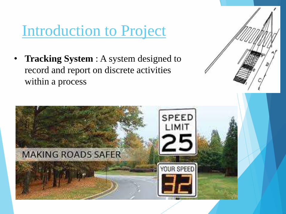
Introduction to Project
• Tracking System : A system designed to
record and report on discrete activities
within a process

Introduction to Project
• Speed checker will come handy for the highway
traffic police as it will not only provide a digital
display in accordance with a vehicle’s speed but
sound an alarm if the vehicle exceeds the permissible
speed for the highway.

Components
Name Cost (Unit Price)
INTEGRATED CIRCUIT
8051 microcontroller 60/-
7805 5/-
SWITCH (PUSH-TO-ON Switch ) 3/-
DIODE (1N4007 PN Diode 0 3/-
CAPACITORS
1000µF 25V 5/
33pF 1/
47µF 50V 2/-
10µF 40V 2/-

Components
Name Cost(Unit Price)
RESISTORS
8.2 KΩ 0.50/-
SIP-Resistor 10KΩ 10/-
CRYSTAL (11.0592MHz ) 15/-
TRANSFORMER 60/-
LCD 280/-
IR LED 50/-
LED 2/-
PRESET 10/-

Block Diagram

100 cm
Concept

Concept
Vehicle Speed = Distance between 2 sensors
Time taken by the timer
• A timer is started inside the microcontroller whenever a
low pulse is received on the first sensor.
• Timer is stopped whenever low pulse is received on
second receiver.

Circuit Diagram

Advantages
The circuit is also running on +5V which is
easier to generate.
They reduce the risk of accidents.
It is easy to implement.
It reduces the man-effort.

Disadvantages
Sometimes the circuit got failure and causes
various problems.
Infrared detectors are extremely expensive,
which limits their use in many sectors

Applications
Bridge construction.
Highways.
Two lane road construction.
Emergency response.
Event Traffic control.

References
1. http://www.engineersgarage.com/
2. http://engineeringactivity.com/
3. http://www.pantechsolutions.net/
4. http://www.8051projects.net/
5. http://www.dnatechindia.com/

