vehicle access control system for utilimaster walk-in vans
TRANSCRIPT

1Operation and Service Manual
Operation& Service
Manual
Vehicle AccessControl System for
Utilimaster Walk-In VansRevision E

2 VACS for Utilimaster Walk-In Vans

3Operation and Service Manual
Important Notices©2006, Utilimaster.®
Printed in U.S.A.
Title: Vehicle Access Control System for Utilimaster Walk-In Vans Operation and Service ManualUtilimaster Corporation attempts to provide information that is accurate, complete, and useful. All informationcontained in this manual is based on the latest product information available at the time of publication. However,because of the Utilimaster policy of continual product improvement, Utilimaster reserves the right to amend theinformation in this document at any time without prior notice. Should you find inadequacies in the text, pleasesend your comments to the following address:
UtilimasterAttn: Designer of Technical Publications65906 State Road 19, P.O. Box 585Wakarusa, Indiana, 46573–0585 U.S.A.574–862–4561, FAX 574–862–3961
This material is confidential and the property of Utilimaster. It is shared with your company for the sole purposeof helping you with the operation of the described equipment. The information contained in this document issubject to change without notice.
Utilimaster makes no warranty of any kind with regard to this material, including, but not limited to, the impliedwarranties of merchantability and fitness for a particular purpose. Utilimaster shall not be liable for errorscontained herein or for incidental or consequential damages in connection with the furnishing, performance, oruse of this material.
Utilimaster expressly disclaims all responsibility and liability for the installation, use, performance, maintenance,and support of third-party products. Customers are advised to make their independent evaluation of suchproducts.
No part of this document may be photocopied, reproduced, or translated to another language without the priorwritten consent of Utilimaster.
Utilimaster® is a registered trademark of Utilimaster Corporation. All other trademarks are products of theirrespective companies.
Browse the web site www.utilimaster.com for more information about Utilimaster and its products.
Revision ControlRevision Print DateInitial Release September 1999Revision B June 2000Revision C March 2001Revision D October 2003Revision E June 2006
Part Number 03102103
For updates and additional information, browse www.utilimaster.com/vacs/. From there, this manual can bedownloaded in Adobe Acrobat format.

4 VACS for Utilimaster Walk-In Vans
Contents
Vehicle Identification Number (VIN), Body Serial Number, and Work Order Numbers ........ 8
VIN ......................................................................................................................................... 8
Body Serial Number ............................................................................................................. 8
Introduction ................................................................................................................................ 8
Work Order Number ............................................................................................................. 9
Recommend Tools ..................................................................................................................... 9
Notes, Cautions, and Warnings .............................................................................................. 10
Operation and Service Information......................................................................................... 11
1.0 Overview ........................................................................................................................ 11
1.1 Definitions................................................................................................................................. 111.2 Part Numbers ........................................................................................................................... 111.3 Types of Master Programming Cards..................................................................................... 121.4 Receiving New Vehicles (Fleets) ............................................................................................. 121.5 Receiving New Vehicles (Owners/Operators) ......................................................................... 121.6 Replacing Control Modules ..................................................................................................... 12
2.0 Fuses ............................................................................................................................. 13
3.0 Vehicle Access Control System (VACS) - Operation ................................................. 14
3.1 Waking Up and Unlocking System ......................................................................................... 143.1.1 Unlock From Outside .......................................................................................................................... 14
3.1.2 Unlock From Inside ............................................................................................................................. 14
3.1.3 Emergency Entrance and Exit .............................................................................................................14
3.1.4 Interior Lights ......................................................................................................................................15
3.2 Starting and Stopping Vehicle .................................................................................................. 153.2.1 Activating Accessories ........................................................................................................................ 15
3.2.2 Starting Engine ....................................................................................................................................15
3.2.3 Stopping Engine ..................................................................................................................................16
3.3 Vehicle Security ...................................................................................................................... 163.3.1 Operating Modes .................................................................................................................................16
3.3.2 Changing Security Mode ...................................................................................................................... 16
3.3.3 Disarming/Deactivation of Alarm ......................................................................................................... 17
3.4 Transponder Programming ..................................................................................................... 173.4.1 Programming via Access Reader ........................................................................................................ 17
3.4.2 Programming via Ignition Reader ......................................................................................................... 19
3.5 FCC Equipment Certification................................................................................................... 19

5Operation and Service Manual
4.0 VACS - Troubleshooting .............................................................................................. 19
4.1 Troubleshooting Access Problems ......................................................................................... 194.1.1 Checking Control Module Harness Voltage .........................................................................................22
4.1.2 Checking Push-button Switch Continuity ............................................................................................22
4.1.3 Checking Access Reader Limits .........................................................................................................22
4.1.4 Checking Latch Activation Voltage .....................................................................................................23
4.1.5 Checking Latch Resistance ................................................................................................................23
4.1.6 Replacing Access Control Module .......................................................................................................24
4.2 Troubleshooting Ignition Problems .......................................................................................... 254.2.1 Ignition Control Module Connector Identification ..................................................................................26
4.2.2 Checking Ignition Reader Antenna Limits - J2 ....................................................................................27
4.2.3 Checking Ignition Reader Switches - J2 ..............................................................................................27
4.2.4 Checking Ignition Reader LEDs - J2 ...................................................................................................28
4.2.5 Checking Ignition Control Module J1 Harness Connector Parameters ................................................28
4.2.6 Checking Door Sensor Switches via Harness Connector J3 ...............................................................28
4.2.7 Checking Interior Lights Relay and Horn Relay Coil via Harness Connector - J3 ................................29
4.2.8 Checking Motion Sensor Harness via connector J3 ............................................................................29
4.2.9 Replacing Ignition Control Module .......................................................................................................30
4.2.10 Adjusting the Motion Sensor ..............................................................................................................30
4.3 Problems Caused by High Voltage on the Communication Bus ............................................. 314.3.1 Overview ..............................................................................................................................................31
4.3.2 Symptoms ...........................................................................................................................................31
4.3.3 Diagnosis ............................................................................................................................................31
4.3.4 Resolution ...........................................................................................................................................31
4.4 Problems After Changing Master Programming Card ............................................................ 334.4.1 Situation ..............................................................................................................................................33
4.4.2 Affected Units .....................................................................................................................................33
4.4.3 Resolution ...........................................................................................................................................33
4.5 Replace a Lost Master Programming Code ........................................................................... 345.0 Service and Maintenance of VACS Components ...................................................... 36
5.1 Latch and Catch Maintenance ................................................................................................ 365.2 General Maintenance .............................................................................................................. 37
5.2.1 Access Readers ..................................................................................................................................37
5.2.2 Harness Connectors ............................................................................................................................37
5.2.3 Door Dead Bolts ..................................................................................................................................37
5.2.4 Door Access Modules .........................................................................................................................38

6 VACS for Utilimaster Walk-In Vans
6.0 Wiring Diagrams ............................................................................................................ 39
6.1 Model Year 1999–May 2001 ................................................................................................... 396.1.1 Wiring Diagram Overview .................................................................................................................... 39
6.1.2 Connectors .......................................................................................................................................... 40
6.1.3 RH Quarter Post .................................................................................................................................41
6.1.4 LH Quarter Post ..................................................................................................................................41
6.1.5 Entry Door Switch ................................................................................................................................41
6.1.6 Dash ....................................................................................................................................................41
6.1.7 Roof .....................................................................................................................................................42
6.1.8 Rear Jumper ........................................................................................................................................ 42
6.2 Model Year May 2001–2003 ................................................................................................... 436.2.1 Wiring Diagram Overview ..................................................................................................................... 43
6.2.2 Connectors .......................................................................................................................................... 44
6.2.3 RH Quarter Post ..................................................................................................................................45
6.2.4 LH Quarter Post ..................................................................................................................................45
6.2.5 Entry Door Switch ................................................................................................................................45
6.2.6 Power Feed ......................................................................................................................................... 45
6.2.7 Dash ....................................................................................................................................................46
6.2.8 Roof .....................................................................................................................................................46
6.2.9 Rear Jumper ........................................................................................................................................ 47
6.3 Model Year 2003 and Later ..................................................................................................... 486.3.1 Wiring Diagram Overview ..................................................................................................................... 48
6.3.2 Connectors .......................................................................................................................................... 49
6.3.3 RH Quarter Post ..................................................................................................................................51
6.3.4 Entry Door Switch ................................................................................................................................51
6.3.5 Power Feed ......................................................................................................................................... 51
6.3.6 Dash Passenger Door Override ...........................................................................................................52
6.3.7 Roof .....................................................................................................................................................53
6.3.8 Rear Jumper ........................................................................................................................................ 54
6.4 Schematic Overview ............................................................................................................... 556.4.1 Model Year 2000–2001 ........................................................................................................................ 55
6.4.2 Model Year 2001½–2003 ..................................................................................................................... 56
6.4.3 Model Year 2003 and Later .................................................................................................................. 57
6.5 Chassis to Body Wiring Interface ........................................................................................... 586.5.1 Horn Interface (Freightliner) .................................................................................................................58
6.5.2 Ignition Interface (Freightliner) .............................................................................................................58
6.5.3 Chassis Interface (1999–2001 Freightliner) .........................................................................................59
6.5.4 Chassis Interface (2001–2003 Freightliner) .........................................................................................59
6.5.5 Chassis Interface (2003 and Later Freightliner) ................................................................................... 60
6.5.6 Chassis Interface (Navistar International) ............................................................................................61
6.6 Circuit Number Identification ................................................................................................... 62

7Operation and Service Manual
7.0 Recessing the Rear Access Reader ............................................................................ 63
7.1 Overview ................................................................................................................................. 637.2 Exploded Parts List ................................................................................................................. 637.3 Procedure................................................................................................................................ 64
8.0 Assembly Drawings...................................................................................................... 67
8.1 Side Door ................................................................................................................................ 678.2 Bulkhead Door ........................................................................................................................ 688.3 Rear Door ................................................................................................................................ 698.4 Ignition Module ........................................................................................................................ 70
8.4.1 (Model Year 1999–2001) ......................................................................................................................70
8.4.2 (Model Year May 2001–2003) ...............................................................................................................71
Appendixes ............................................................................................................................... 72
VACS Operator's Guide ...................................................................................................... 72
VACS Programming Guide................................................................................................. 74
Filing Warranty Claims............................................................................................................. 76
Ordering Parts .......................................................................................................................... 77
How to Order ....................................................................................................................... 77
Returns ................................................................................................................................ 77
Parts Order Form ................................................................................................................ 78
Reporting Safety Defects ......................................................................................................... 79
United States Only .............................................................................................................. 79
Canada Only ........................................................................................................................ 79
Towing and Emergency Repairs ........................................................................................ 79
More Information ..................................................................................................................... 80
Download Files ................................................................................................................... 80
Utilimaster Quick Reference Parts Guide ......................................................................... 80
Utilimaster Detailed Parts and Wiring Manuals ................................................................ 80
Contact Utilimaster ............................................................................................................. 80
Index.......................................................................................................................................... 81

8 VACS for Utilimaster Walk-In Vans
Vehicle Identification Number (VIN), Body Serial Number,and Work Order NumbersVIN
The 17-digit chassis Vehicle Identification Number (VIN)is the legal identifier for this vehicle and is the numberrecorded in the license plate registration. The VIN appearson a label on the dash cowl extrusion on the driver’s side.You can read the VIN if you look through the quarter-panelwindow. (See Illustrations LA–10 and LA–12.) The numberis also recorded on the Federal Certification Label. (SeeIllustration LA–20.)
Body Serial Number
The 15-digit Utilimaster Body (or Unit) Serial Number isrecorded on the Federal Certification Label. This label isa plastic decal (about 11" long and 2" high) thatcontains a variety of manufacturing information(including the VIN). This label is found between thequarter window and door. (See Illustrations LA–15and LA–20).
LA–12Vehicle Identification Number Beside Dash
IntroductionThis manual lists operation, service, and maintenance procedures for Vehicle AccessControl System (VACS) in Utilimaster walk-in van bodies. It contains drawings andprocedures to aid in servicing the vehicle. This manual covers only those assembliesmanufactured by or installed by Utilimaster® Corporation. Items such as chassis anddrive train components or certain interior furnishings are covered by separatemanufacturer-supplied information.
NOTE: This service information is generic. Details in illustrationsand procedures may differ from the VACS installation in your vehicle. Use thisinformation as a guideline where it applies.
All information, specifications, and illustrations contained in this manual are based on the latest productinformation available at the time of publication. Utilimaster reserves the right to amend the information in thisdocument at any time without prior notice.
LA–10Vehicle Identification Number

9Operation and Service Manual
LA–15Federal Certification Label on
Door Post
Work Order Number
A 7-digit Work Order Number appears below the Unit Serial Number on theFederal Certification Label. (See Illustration LA–20.)
LA–20Federal Certification Label
Recommend ToolsBelow are some tools that may also be required in addition to the more commonly used hand tools (drills,wrenches, etc.) in vehicle body repair.
• Torque wrenches (any quality sets with in•lb and ft•lb [or N•m] measurements)
• DVOM (Digital Voltmeter)
• Terminal tool kit (Snap-On TT600 recommended)
• Terminal extraction tool (Mini-FitTM 11-03-0044 recommended)
• Memory saver

10 VACS for Utilimaster Walk-In Vans
NOTE: This service information is generic. Details in illustrations and proceduresmay differ from your vehicle. Use this information as a guideline where it applies.
Notes, Cautions, and WarningsAs you read through the procedures, you will come across NOTES, CAUTIONS, andWARNINGS. Each one is there for a specific purpose.
• NOTES give you additional information that will help you to complete the procedure.
• CAUTIONS warn you against making an error that could damage the vehicle.
• WARNINGS remind you to be careful when there is a risk of personal injury.
Below are some basic WARNINGS that you should heed when you work on the vehicle’s body. They are notall inclusive, however, and common sense must be used when servicing vehicles.
• Always read and understand all the instructionsbefore starting the repair
• Always wear safety glasses and wear otherproper protective equipment (gloves, steel-toedshoes, face shields, knee pads, hearingprotection) as appropriate to the process.
• Use safety stands and/or wheel blockswhenever you are underneath the vehicle.
• Put the transmission in Park and set the parkingbrake before working on the vehicle.
• Be sure that the ignition switch is Off unlessotherwise required by the procedure.
• Operate engines only in well-ventilated areas.
• Keep yourself and your clothing away from theradiator fan, belts, and any moving parts whenthe engine is running.
• Keep hands and other objects clear of theradiator fan blades. The electric fan can startat any time even though the ignition is Off.Disconnect the fan when working under thehood.
• Avoid contact with hot metal parts, such as theradiator or exhaust system.
• Always remove rings, watches, hanging jewelry,and loose clothing before working on a vehicle.Tie long hair securely behind your head.
• Become familiar with all warning labels.
• Use only tools that are in good condition, anduse them only in the appropriate manner.
• If at any time you are not confident thatperform the described repairs or operate theneeded tools safely and correctly, STOP!Call your local dealer or Utilimasterrepresentative.

11Operation and Service Manual
Operation and Service Information1.0 Overview
1.1 Definitions
VACS is a combined vehicle access, control, and security system which utilizes Radio Frequency Identification(RFID) technology. This system allows a driver to enter and start a vehicle without a mechanical key whilemaintaining a high level of security. The system is composed of the following components:
Wristband Transponder (arrow) and(optional) Ignition Reader
Control Module
Master Programming Card Access Reader
1.2 Part Numbers
Actuator, LH side and bulkhead door P/N 08610834 598830AC1Actuator, RH side door P/N 08610835 598842AC1Actuator, rear roll-up door P/N 08610836 599507AF1Control module P/N 16512776 599072AB1Reader P/N 16512777 599073AA1Transponder with wristband P/N 16512627 599074AA1Wristband only (12") P/N 21000525 3955T347

12 VACS for Utilimaster Walk-In Vans
1.4 Receiving New Vehicles (Fleets)
When new VACS-equipped vehicles are shipped from Utilimaster, their VACS systems are usuallyprogrammed to recognize the universal T1000 transport programming card. When the fleet customerreceives the vehicle, that vehicle’s system should be reprogrammed to recognize the customer’s unique depot(or station) programming card. For this procedure, see Section 3.4.1.3 of this manual or Mode 3 on theVACS Programming Guide (included as an appendix in this manual).
After reprogramming the system, keep the T1000 card in a safe place in case a control module ever needsreplacing.
1.5 Receiving New Vehicles (Owners/Operators)
When new VACS-equipped vehicles are shipped from Utilimaster to owner/operators, their VACS systems areusually already programmed to recognize the customer’s unique (unit) programming card. However, they stillreceive a T1000 card in case a control module ever needs replacing.
1.6 Replacing Control Modules
After an Access Control Module (see Section 4.1.5) or Ignition Control Module (see Section 4.2.9) isreplaced, the new module must be resynchronized with the other modules. Both a T1000 transportprogramming card and the customer’s unique depot programming card are required for this procedure.
Card Features T1000 Transport Card Depot (or Station) CardLabel (on back) T1000 A different 5-digit numeric codeCodes Universal (all the same) Unique for location/unitFunction(fleets)
• Delivery of new vehicles• Replacing control modules
• Normal programming• Replacing control modules
Function(owners/operators)
• Replacing control modules • Normal programming• Replacing control modules
1.3 Types of Master Programming Cards

13Operation and Service Manual
2.0 Fuses
In addition to the chassis fuses (that vary per manufacturer) there are two replaceable blade fuses on the body.One is located at the vehicle batteries (Illustration VA–02) and one outside the horn box (Illustration VA–04).
Illustration VA–04Fuse by horn box
Illustration VA–02Fuse at battery
NOTE: This service information is generic. Details in illustrations and proceduresmay differ from your vehicle. Use this information as a guideline where it applies.

14 VACS for Utilimaster Walk-In Vans
3.0 Vehicle Access Control System (VACS) - Operation
3.1 Waking Up and Unlocking System
NOTE: The door latches may be electronically activated a maximum of 3 times per minute. If this rateis exceeded, then the red LED on the Access Reader will flash and the reader will be inoperative untilthe rate limit has been met.
NOTE: For optimum performance, hold a wristband or key fob transponder 3–6 inches from the AccessReader.
If the vehicle is unused for greater than an hour, then it is necessary to wakeup the system using one of the following methods:
••••• Hold the transponder in position by any Access Reader for up to 5seconds.
••••• Pressing an interior door release switch.
••••• Starting the engine
3.1.1 Unlock From Outside
• To unlock a cab exterior door from the outside, the rear door from theoutside, or the bulkhead door from the cab side, slowly pass thetransponder in front of the access reader. This will unlock the door for 5seconds.
3.1.2 Unlock From Inside
NOTE: A transponder is not required to open a door from the inside.
• To open a cab door from inside the cab, press the door unlock switch(mounted on the dash). This will unlock the door for 5 seconds.
• To open the bulkhead door from inside the cargo area, press the button
mounted beside the bulkhead door. This will unlock the door for 5seconds.
• To open the rear door from inside the cargo area, press the buttonmounted beside the rear door. This will unlock the door for 5 seconds.
• The side and bulkhead doors may be unlocked manually by pushing the
tab on the locking mechanism and pulling the door at the same time.
• The rear roll-up door may be unlocked manually by pushing the tab which is located on the bottomof the locking mechanism while unlatching and pulling the door up.
3.1.3 Emergency Entrance and Exit
• In the event of a dead battery, the vehicle may be entered with a key
via the rear roll-up door. Remove the reflective decal if present toallow key insertion.
• Each door deadbolt can be manually operated from the interior.
Open door (inside)
AlternateKey Access
Open door (outside)
Wake up
5 seconds
15Operation and Service Manual
Start engine
3.1.4 Interior Lights
The interior lights will turn on when:
• A transponder is read by one of the Access Readers.
• One of the doors is opened.
• The ignition is shut off
The interior lights will turn off again after 10–60 seconds.
• If no doors are opened after the interior lights are activated, the lights will extinguish after 10seconds.
• If a door is opened, the lights will extinguish 10 seconds after the door is closed.
• If a door is left open, the interior lights will extinguish after 60 seconds.
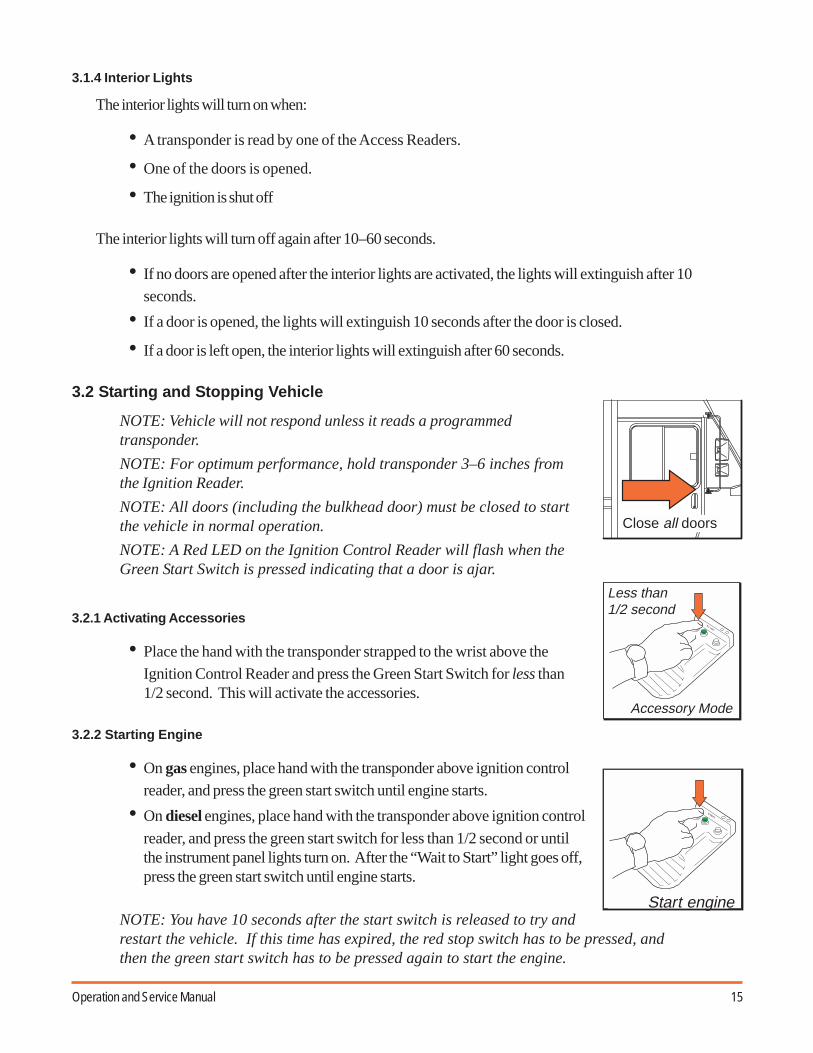
3.2 Starting and Stopping Vehicle
NOTE: Vehicle will not respond unless it reads a programmedtransponder.
NOTE: For optimum performance, hold transponder 3–6 inches fromthe Ignition Reader.
NOTE: All doors (including the bulkhead door) must be closed to startthe vehicle in normal operation.
NOTE: A Red LED on the Ignition Control Reader will flash when theGreen Start Switch is pressed indicating that a door is ajar.
3.2.1 Activating Accessories
• Place the hand with the transponder strapped to the wrist above theIgnition Control Reader and press the Green Start Switch for less than1/2 second. This will activate the accessories.
3.2.2 Starting Engine
• On gas engines, place hand with the transponder above ignition controlreader, and press the green start switch until engine starts.
• On diesel engines, place hand with the transponder above ignition control
reader, and press the green start switch for less than 1/2 second or untilthe instrument panel lights turn on. After the “Wait to Start” light goes off,press the green start switch until engine starts.
NOTE: You have 10 seconds after the start switch is released to try andrestart the vehicle. If this time has expired, the red stop switch has to be pressed, andthen the green start switch has to be pressed again to start the engine.
ST ART
Less than 1/2 second
Accessory Mode
Close all doors

16 VACS for Utilimaster Walk-In Vans
ST OP
Stop engine
Operating modes
Door open
Doorclosed
3.2.3 Stopping Engine
NOTE: No transponder is needed to shut off the accessories or the engine.
• Press the Red Stop Switch for more than 1/4 second. The engine will stop, and interior lights will
activate for 10 seconds.
3.3 Vehicle Security
NOTE: All doors must be closed to start vehicle in normal operation.
3.3.1 Operating Modes
NOTE: If the alarm is disarmed/deactivated and the vehicle is notstarted or in accessory mode, the system will arm itself after 10 seconds.
VACS has two operating modes. To toggle between modes (while in accessory mode or when engine isrunning), press the black mode button.
• Door Opened (Red LED): The security system will be armed 10 seconds after any exterior dooris opened.
• Door Closed (Yellow LED): The security system will be armed 10 seconds after all exterior doors
are closed.
• Maintenance (No LED–Available only through programming card: Thesecurity system will not activate. The vehicle may be started with opendoors.
3.3.2 Changing Security Mode
NOTE: Starting the engine with a Programming Card will automaticallyplace the vehicle in maintenance mode.
NOTE: Maintenance mode cannot be entered with a wrist band.
1. Place ignition in either Accessories On or Engine Run mode using a Wristband Transponder orProgramming Card.
2. Using either a Wristband Transponder or Programming Card, press the Black Alarm Control Switch.
When using the Programming Card, modes will cycle between:• Door Open–Red LED illuminated.• Door Closed–Yellow LED illuminated.• Maintenance–No LED illuminated.
When using a Wristband Transponder, modes will cycle between:• Door Open–Red LED illuminated.• Door Closed–Yellow LED illuminated.

17Operation and Service Manual
3.4 Transponder Programming
NOTE: See also the VACS Programming Guide (P/N 03102519-RY01EN), which is asingle laminated sheet for easy reference (and reproduced as an appendix in the back ofthis manual).
• Programming can be conducted at any of the readers on the vehicle. (See Section 3.4.2 for IgnitionReader programming.) All system modules will receive the new codes via a communications bus.
• The system can hold up to 10 unique codes.• All Access Readers which are not the source of programming will be inactive while in programming
mode. This state is indicated by constant illumination of the Red LED.• The system provides three programming functions.
! ! ! ! ! Add new transponder codes to an existing bank of codes in memory (10 maximum).! ! ! ! ! Delete existing transponder codes in memory and add new codes.! ! ! ! ! Change Programming Card and delete existing transponder codes in memory.
3.4.1 Programming via Access Reader
3.4.1.1 Add New Transponder Codes to an Existing Bank of Codes in Memory
1. Slowly pass the Programming Card by the Access Reader and observe that the red LED in the AccessReader will flash once. This indicates that the system is in the add mode of operation.
2. Slowly pass a non-programmed transponder by the Access Reader and observe that the red LED willquickly flash twice. This indicates that the transponder has been added to the system’s memory.
3. You may continue to add codes to the system’s memory by simply passing non-programmed transpon-ders by the Access Reader.
There are four methods of exiting this mode of operation.• Pass a programmed transponder by the reader (for example, the transponder that was just added).• Pass the Programming Card by the reader.• Programming mode will be exited automatically after 10 codes have been stored.• Programming mode will be exited automatically after 5 minutes of inactivity.
NOTE: The Red LED will illuminate for approximately 1 second to indicate that theoperator has exited the programming mode.
3.3.3 Disarming/Deactivation of Alarm
The Alarm can be deactivated by any of the following methods:
• A valid transponder code is read by an Access Reader.• Starting the vehicle with a valid transponder or Programming Card.• Placing the vehicle in Programming mode via the Ignition Switch Module.• Alarm will cease after three minutes of continuous activation.
NOTE: If the alarm is disarmed/deactivated and the vehicle is not started or put inaccessory mode, the system will arm itself after 10 seconds.
ST ART
Disarm alarm

18 VACS for Utilimaster Walk-In Vans
3.4.1.2 Delete Current Transponder Codes in Memory and Add New Codes
1. Slowly pass the Programming Card by the Access Reader once, and then pass it by the reader asecond time. The red LED in the Access Reader will flash once and then twice. This indicates that thesystem is in the delete mode of operation.
2. Slowly pass a transponder by the Access Reader. The Red LED will quickly flash twice. This indicatesthat all existing codes in memory have now been deleted and the current transponder has been added tothe system’s memory.
3. You may continue to add codes to the system’s memory by simply passing non-programmed transpon-ders by the Access Reader.
There are four methods of exiting this mode of operation.• Pass a programmed transponder by the reader.• Pass the Programming Card by the reader.• Programming mode will be exited automatically after 10 codes have been stored.• Programming mode will be exited automatically after 5 minutes of inactivity.
NOTE: The Red LED will flash once to indicate that the operator has exited the program-ming mode.
3.4.1.3 Add a New Programming Card and Delete Existing Transponder Codes in Memory
1. Slowly pass the Programming Card by the Access Reader once, twice, and again a third time whileobserving that the Red LED in the Access Reader will flash once, and then twice, and then three times.This indicates that the system is in the Add New Programming Card mode of operation.
NOTE: If the existing Programming Card is passed by the Access Reader a fourth time,the red LED will flash once indicating that the operator has exited the programmingmode with no changes made to the stored codes.
2. Slowly pass the desired Programming Card by the Access Reader three consecutive times. Each timethe new card is passed, the red LED indicator will flash once for each time the card has been passed.After the third pass the system will save the new Programming Card, delete all existing user codes, andexit the programming mode automatically.
NOTE: The red LED will illuminate for approximately one second to indicate that theoperator has exited the programming mode.
NOTE: If the new Programming Card is not presented three consecutive times (i.e., anyother code is entered after the new Programing Card has been presented at least once),then the programming mode will be exited immediately and no changes will occur.
NOTE: To add codes to the system, use the new Programming Card and enter the AddCodes mode of operation.

19Operation and Service Manual
3.4.2 Programming via Ignition Reader
NOTE: Programming Modes can only be entered when the vehicle is off.
NOTE: The vehicle is not allowed to start if programming from the Ignition Control Reader.
Instructions for Access Readers apply with the following additions/exceptions:
• Hold the Programming Card above the Ignition Reader and press the Black Alarm Control Switchin order to activate programming mode.
• Press the Black Alarm Control Switch in order to add and delete codes while holding the new
transponder above the Ignition Reader.
• Pressing the Black Control Switch while holding a programmed transponder will not result in anyaction.
• Press the Red Stop Switch to exit programming mode.
• Black Alarm Control Switch is pressed to simulate passing the programming card by an AccessReader.
3.5 FCC Equipment Certification
This device complies with FCC rules Part 15. Operation is subject to the following two conditions:
1. This device may not cause harmful interference.
2. This device must accept any interference received, including that causing undesired operation.
4.0 VACS - Troubleshooting
4.1 Troubleshooting Access Problems
Perform the following steps then refer to Table 1.
1. Verify that both connectors at the Access Control Module are fully inserted.
2. Press the release switch and note the status of the Reader LED and the latch.
3. Use a wristband transponder and note the status of the reader LED and the latch.

20 VACS for Utilimaster Walk-In Vans
Table 1a Access Troubleshooting
Problem Probable Cause Recommended Action
Neither the release switchnor the transponder activatethe Door Latch and theReader LED.
Defective wire harness. Novoltage at control module.
Access Control Module.
Access Reader and Push-button switch.
1. Check voltage at control module connector. Ifvoltage is within limits per section 4.1.1 theninvestigate the next probable cause.
2. If voltage is not present then troubleshoot andreplace or repair harness.
3. Disconnect the 10-pin connector from the controlmodule (if not done so from the previous step)and leave disconnected for approximately 1minute.
4. Reconnect the 10-pin connector. The redindicator on the Access Reader will flash from 1to 16 times. While the indicator is flashing, thecontrol module will not respond to inputs.
5. Check the operation of the latch with the releaseswitch and via the reader with a known validtransponder. If both fail to activate the latch thenreplace the control module per section 4.1.5.
6. If either the release switch or the transpondercauses the latch to activate then investigate thenext probable cause prior to replacing the controlmodule.
7. Verify that both the release switch and the readerassembly are functional and within specificationsper sections 4.1.2 and 4.1.3.
Door Latch does not respondto push-button switch. (Doesrespond to Transponder.)
Defective Push-buttonSwitch or switch wiring.
Access Control Module.
1. Check continuity of switch at control moduleconnector per section 4.1.2. If continuity ispresent then investigate the next probable cause.
2. If no continuity is present then check at switch.Replace switch or repair wiring as necessary.
3. Replace control module per section 4.1.5.
Door reader (Latch) does notrespond to a programmedTransponder. (Does respondto the release switch.)
Transponder defective or notprogrammed in system.
Access Reader.
Access Control Module.
1. Check transponder at another door reader or onanother vehicle.
2. If transponder is functional then tryreprogramming it in the non-responding reader.If it does not program into the system or there isno activity at the reader then investigate the nextprobable cause.
3. Check reader per section 4.1.3. If measurementsare within limits then investigate next probablecause.
4. Replace control module per section 4.1.5.

21Operation and Service Manual
Table 1b Access Troubleshooting
Problem Probable Cause Recommended Action
Red LED illuminates but Latchdoes not activate.
Defective Latch.
Access Control Module.
1. Check latch activation voltage at connector persection 4.1.4. If voltage is within limits thenreplace latch. If voltage is not within limits theninvestigate the next probable cause.
2. Replace control module per section 4.1.5.
Latch activates but red LED doesnot illuminate.
Access Reader.
Access Control Module.
1. Check reader per section 4.1.3. If measurementsare within limits then investigate next probablecause.
2. Replace control module per section 4.1.5.
(In order of probability:)
A solenoid activated door latchcycles too fast (does not stay openfor 5 seconds)
The engine will not start with theVACS, the red LED indicates adoor is open although all doorsare closed.
The engine will not shut off withthe VACS.
When programming the VACS,not ALL door reader LEDs lightup.
The VACS alarm sounds whenopening an exterior door with avalid transponder.
When attempting to start theengine, the cargo/dome lightsblink in sequence with the redLED on the ignition reader.
High voltage situation atthe communication bus.
1. Check the voltage at J1 connector. (See Section4.3.)
2. Diagnosis and isolate the module.
3. Replace the defective module.

22 VACS for Utilimaster Walk-In Vans
NOTE: Connector Mating View
! "#$%&&'
4.1.1 Checking Control Module Harness Voltage
Measure the voltage between terminals 10 and 5 with a DVM.
4.1.2 Checking Push-button Switch Continuity
1. Measure the resistance between terminals 3 and 7 with a DVM.
2. With the Push-button pressed the measurement should be < 10 Ω.
3. With the Push-button released the measurement should be > 100K Ω.
4.1.3 Checking Access Reader Limits
NOTE: Terminals are located in connector locations 3, 4 ,7 and 8 only.1. Check Antenna continuity by measuring resistance between terminals 8 and 4 with
a DVM.
2. Check LED continuity by measuring voltage between terminals 7(+) and 3(–) witha DVM that is set to the diode test function.

23Operation and Service Manual
10.5 - 12.5 V1
2+
-
BK/WT
BK/WT
4.1.4 Checking Latch Activation Voltage
Measure the voltage between terminals 1 and 2 with a DVM while the output is activated.
5 6
1 2 3 4
RD
BK
7 82.5 - 4 Ohm
+
-
1.4 - 1.7V
BK
WT
NOTE: Connector Mating View
4.1.5 Checking Latch Resistance
Measure the resistance between terminals 1 and 2 with a DVM.
NOTE: Resistance less than .5 OHMS indicates a defective activator.
NOTE: Connector Mating View
"()
"()

24 VACS for Utilimaster Walk-In Vans
4.1.6 Replacing Access Control Module
NOTE: Whenever an Access Control Module is replaced, the Programming Card and alldesired wristband or key fob transponders must be reentered.
1. Prior to replacement, verify that no transponder or Programming Cards are within close proximity (< 3feet) of any Access Reader on the vehicle.
2. Disconnect the 10-pin (larger) connector then the 8-pin (smaller) connector and remove the defectivemodule.
3. Install the new module. Reconnect the 8-pin connector and the 10-pin connector.
4. At another door location use the existing “Depot” Programming Card to convert to the T1000“Transport” Programming Card (per Section 3.4.1.3). Then immediately, use the T1000 ProgrammingCard to transfer back to the desired Depot Programming Card (again per Section 3.4.1.3). See alsoSection 1.0.
5. At any location on the vehicle reprogram all desired transponders (per Section 3.4.1.2).
6. Verify functionality of all transponder at all locations. Please note that each door latch can be activateda maximum of three times per minute. After the third activation (in less than one minute) the red indica-tor on the reader will flash until one minute after the first activation has expired.
NOTE: See also Section 4.4.

25Operation and Service Manual
4.2 Troubleshooting Ignition Problems
Table 2a Ignition/Security Troubleshooting
Problem Probable Cause Recommended Action
Does not respond to Readerswitch activation.
Ignition Reader Module.
Defective wire harness. Novoltage at control module.
Ignition Control Module.
Switches not depressed longenough.
Interference from CRT (ifapplicable) or other metallicobjects.
1. Check reader antenna and switches per sections4.2.2 and 4.2.3. If measurements are withinlimits, then investigate next probable cause.
2. Check connector terminals for signs of severedeformation, excessive contamination, or poorcrimp connections. Repair or replace ifnecessary.
3. Check J1 supply voltage per 4.2.5 (step 1). Ifmeasurements are within limits then replace thecontrol module.
4. Disconnect connectors J3 and J1 (if not done sofrom previous step) and leave disconnected forapproximately 1 minute.
5. Reconnect J1 and J3. The red indicator on theIgnition Reader will flash from 1 to 16 times.While the indicator is flashing, the ControlModule will not respond to inputs.
6. If the Control Module fails to respond to thereader switch input with a known valid wristbandthen replace the Control Module per section4.2.9.
7. If the system functions properly afterreconnecting the harness then investigate the nextprobable causes.
8. Switches need to be depressed a minimum of 0.5sections.
9. Remove or move metallic objects from thevicinity of the Reader Module.
10. Reposition CRT.
LEDs do not illuminate. Ignition Reader Module.
Ignition Control Module.
1. Check reader LEDs per section 4.2.4. Ifmeasurements are within limits then investigatenext probable cause.
2. Replace control module per section 4.2.9.
Reader LED(s) function butone or more ignition relaysnot activating.
Relays, wire harness.
Ignition Control Module.
1. Check the affected relay coil resistance at the J1connector per section 4.2.5 (Steps 2–4).
2. If measurements are not within limits then replacerelay or repair harness as necessary.
3. Replace control module per section 4.2.9.

26 VACS for Utilimaster Walk-In Vans
Ignition Module, Top View
Table 2b Ignition/Security Troubleshooting
4.2.1 Ignition Control Module Connector Identification
Problem Probable Cause Recommended Action
Reader indicates open doorwhen all doors are closed.
Misadjusted defective doorsensor switches.
Wire harness.
Ignition Control Module.
1. At each (or suspected) door location, check forbare, pinched or shorted wires.
2. Independently check each switch by disconnectingone wire and checking continuity in both the dooropen and door closed state. When the door isclosed, check while pulling to extreme positions toverify if an intermittent condition exists. Replaceor adjust switch/magnet as necessary.
3. Check door inputs via harness connector J3 persection 4.2.6. Troubleshoot and repair asnecessary.
4. Replace control module per section 4.2.9.
Interior Lights or Horn notactivated by system.
Relays, wire harness.
Ignition Control Module.
1. Check the affected relay coil resistance at the J3connector per section 4.2.7.
2. If measurements are not within limits then replacerelay or repair harness as necessary.
3. Replace control module per section 4.2.9.
Nuisance alarms. Misadjusted improperlymounted motion sensor(s).
Intermittent short in wireharness.
1. Check that each sensor is securely mounted.2. Reduce sensitivity of suspected sensor per section
4.2.10.
3. Disconnect motion sensor(s) and check harnesscontinuity at harness connector J3 per section 4.2.8.

27Operation and Service Manual
4.2.2 Checking Ignition Reader Antenna Limits - J2
Check antenna continuity by measuring resistance between terminals 10 and 5 with a DVM.
4.2.3 Checking Ignition Reader Switches - J2
1. Measure the resistance between the appropriate terminals with a DVM.2. With the Push-button pressed the measurement should be < 10 Ω.3. With the Push-button released the measurement should be > 100K Ω.
6
1 2 3 4
BK
7 82 - 3.5 Ohm
WT
9 10
5
< 10 OHM
>100K OHM
STOP SWITCH
PRESSED
RELEASED
6
1 2 3 4
7 8 9 10
5
BK
BK
< 10 OHM
>100K OHM
MODE SWITCH
PRESSED
RELEASED
6
1 2 3 4
7 8 9 10
5
BK
BLU
6
1 2 3 4
7 8 9 10
5
< 10 Ohm
>100K Ohm
START SWITCH
PRESSED
RELEASED
BK
GRN
6
1 2 3 4
7 8 9 10
5
NOTE: Connector Mating View

28 VACS for Utilimaster Walk-In Vans
NOTE: Connector Mating View
1.5 - 1.8V6
1 2 3 4
7 8 9 10
5
BK
YELLOWRED
1.6 - 2.0V
-
+
-
+
BK
YEL
RD
< 10 Ohm
>100K Ohm
BULKHEADDOOR
OPENED
CLOSED
< 10 Ohm
>100K Ohm
EXTERIORDOORS
OPENED
CLOSED
6
1 2 3 4
7 85
DG
DG/WT
4.2.4 Checking Ignition Reader LEDs - J2
Check LED continuity by measuring voltage between the appropriate terminals with a DVM that is setto the diode test function.
6
1 2 3 4
7 8+
-
IGNITION ACCESSORY START5
11.5 - 13.6V
VT
70 - 110 Ohm 70 - 110 Ohm 70 - 110 Ohm
YLPKRD
OR/BK
BK
Com Bus
4.2.5 Checking Ignition Control Module J1 Harness Connector Parameters
NOTE: Disconnect connector J3 prior to disconnecting connector J1.
1. Measure the control module supply voltage between terminals 8 and 4 with a DVM.
2. Measure the ignition relay coil resistance between terminals 3 and 2 with a DVM.
3. Measure the accessory relay coil resistance between terminals 7 and 2 with a DVM.
4. Measure the starting relay coil resistance between terminals 6 and 2 with a DVM.
5. Reconnect connector J1 prior to reconnecting connector J3.
4.2.6 Checking Door Sensor Switches via Harness Connector J3
1. Measure the resistance between the appropriate terminals and chassis ground with a DVM.
2. With the door(s) open the measurement should be < 10 Ω.
3. With the door(s) closed the measurement should be > 100K Ω.

29Operation and Service Manual
4.2.7 Checking Interior Lights Relay and Horn Relay Coil via Harness Connector - J3
1. Measure the interior lights relay coil resistance between terminals 1 and 2 with a DVM.
2. Measure the horn relay coil resistance between terminals 1 and 5 with a DVM.
4.2.8 Checking Motion Sensor Harness via connector J3
1. Disconnect motion sensor(s).
2. Measure the resistance between the appropriate terminals and chassis ground with a DVM.
1 2 3 4
7 85
PK/BK
70-110 Ohm 70-110 OhmINTERIORLIGHTS HORN6
LB
OR
1 2 3 4
7 85
DB/WT
6
DB
>100K OhmCARGOSENSOR >100K Ohm
CABINSENSOR
NOTE: Connector Mating View
30 VACS for Utilimaster Walk-In Vans
INNERZONE
OUTERZONE
Motion Sensor Adjustment
4.2.9 Replacing Ignition Control Module
NOTE: Whenever an Ignition Control Module is replaced, the Programming Card and alldesired wristband transponders must be reentered.
1. Prior to replacement verify that no transponder or Programming Cards are within close proximity (< 3feet) of any Access Reader on the vehicle.
2. Disconnect connector J3, then J2 and J1, and remove the defective module.
3. Install the new module. Reconnect J1, J2, and J3.
4. At any door location use the existing “Depot” Programming Card to convert the T1000 “Transport”Programming Card (per Section 3.4.1.3). Then immediately, use the T1000 Programming Card totransfer back to the desired Programming Card (again per Section 3.4.1.3). See also Section 1.0.
5. At any location on the vehicle, reprogram all desired wristband transponders (per Section 3.4.1.2).
6. Verify functionality of all transponders at all locations. Please note that each door latch can be activateda maximum of 3 times per minute. After the third activation (in less than 1 minute), the red LED indica-tor light on the Reader will flash until 1 minute from the first activation has expired.
NOTE: See also Section 4.4.
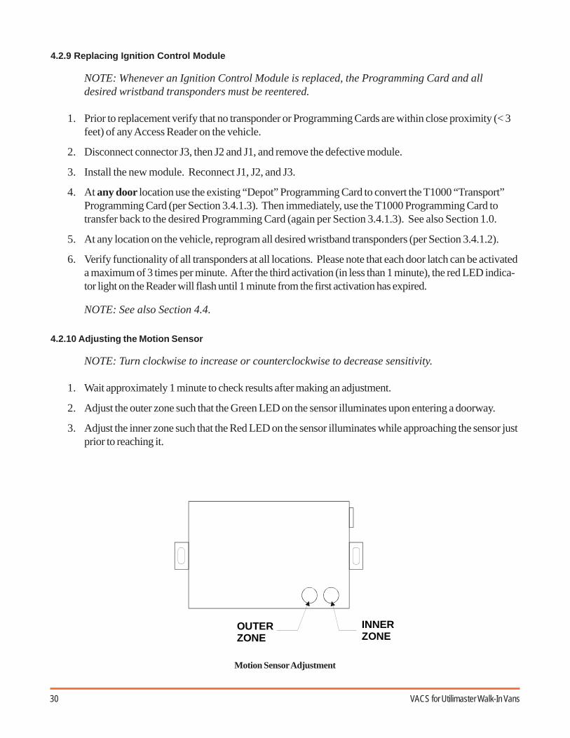
4.2.10 Adjusting the Motion Sensor
NOTE: Turn clockwise to increase or counterclockwise to decrease sensitivity.
1. Wait approximately 1 minute to check results after making an adjustment.
2. Adjust the outer zone such that the Green LED on the sensor illuminates upon entering a doorway.
3. Adjust the inner zone such that the Red LED on the sensor illuminates while approaching the sensor justprior to reaching it.

31Operation and Service Manual
4.3 Problems Caused by High Voltage on the Communication Bus
4.3.1 Overview
The VACS system installed on some vehicles has displayed characteristics that have been cause for confusionand misdiagnosing component failures. A high voltage condition at the communication bus can create a varietyof symptoms that should be checked before replacing any components.
4.3.2 Symptoms
In order of probability:
1. A solenoid activated door latch cycles too fast (does not stay open for 5 seconds)
2. The engine will not start with the VACS, the red LED indicates a door is open although all doors areclosed.
3. The engine will not shut off with the VACS.
4. When programming the VACS, not ALL door reader LEDs light up.
5. The VACS alarm sounds when opening an exterior door with a valid transponder.
6. When attempting to start the engine, the cargo/dome lights blink in sequence with the red LED on theignition reader.
4.3.3 Diagnosis
1. Locate the J1 connector on the ignition module (see Section 4.2.1).
2. Locate circuits 5 and 1 in the J1 connector (see Section 4.2.5).
3. Both circuits 5 and 1 are positive circuits. With the J1 connector plugged into the ignition module, insertthe positive probe from the DVM into circuit 5 or 1 and touch the negative probe from the DVM to anygrounded surface.
4. The typical correct voltage should be 0.22V to 0.66V, and it should fluctuate. (Any reading less than 1Vis acceptable.)
5. The typical high incorrect voltage is 2.3V to 5.8V, and it will not fluctuate. (Any reading of more than1V is unacceptable.)
6. Both circuits 5 and 1 should read approximately the same voltage.
4.3.4 Resolution
1. Once the existence of the high voltage condition is confirmed, certain critical steps must be followed toensure correct repair.
2. Even though the voltage readings are measured at the ignition module, the high voltage condition couldbe generated by any of the modules.
32 VACS for Utilimaster Walk-In Vans
3. The modules must be disconnected one at a time to determine which module is causing the problem.
4. Disconnect the C822 connector at the rear door module (see Section 6.1 and 7.1).
5. Go back to the ignition module and follow Steps 1–6 in Section 4.3.3 above.
6. If the voltage readings drop to the correct level, as shown in Step 4 of Section 4.3.3, you have justidentified the module that is causing the problem.
7. If the voltage readings remain at the incorrect level, as shown in Step 5 of Section 4.3.3, leave the reardoor module disconnected, and move to the bulkhead door module.
8. Disconnect the C816 connector at the bulkhead door module.
9. Go back to the ignition module and follow Steps 1–6 in Section 4.3.3 above.
10. If the voltage readings drop to the correct level, as shown in Step 4 of Section 4.3.3, you have justidentified the module that is causing the problem.
11. If the voltage readings remain at the incorrect level, as shown in Step 5 of Section 4.3.3, leave the reardoor module and the bulkhead door module disconnected, and move to the RH door module.
12. Continue following this process of elimination until you find the module that is causing the problem.
13. If all door modules are disconnected, but you still have the incorrect high voltage, the ignition module isthe module probably causing the problem, since it is the only one still connected.
14. When the module is identified that is causing the problem, then reconnect all the modules to theharnesses.
NOTE: It is important that the module causing the problem is identified prior todisconnecting the batteries, as the high voltage condition on the communication bus maybe lost when power is cycled to the VACS.
15. After ALL modules are reconnected to the harnesses, disconnect the chassis batteries, and load testeach battery individually.
16. If the battery(s) do not withstand a load test, replace them.
17. Connect the new battery(s). The incorrect high voltage condition should be resolved, and no additionalaction should be required with the VACS components.
18. Go back to the ignition module and follow Steps 1–6 in Section 4.3.3 above.
19. If the incorrect high voltage condition continues to exists, replace the module identified in Steps 4–12.
20. If the battery(s) do withstand a load test. Reconnect the battery(s).
21. Go back to the ignition module and follow Steps 1–6 in Section 4.3.3 above.
22. If the incorrect high voltage condition continues to exists, replace the module identified in Steps 4–12.
23. Whenever a module is replaced, you need to reprogram the VACS (see Section 4.1.5 and 4.2.9).

33Operation and Service Manual
4.4 Problems After Changing Master Programming Card
4.4.1 Situation
Vehicles equipped with Keyless Entry or VACS systems may experience an anomaly when changing from onemaster programming card to another. This could occur in the following cases:
• When changing from the transport programming card (T1000) to the unique depot programmingcard or vice versa. See Section 1.0.
• When a vehicle is transferred in from another depot where it was already in service.• When any control module on the vehicle is replaced.• When a new master programming card is needed because existing programming cards are no longer
in use.When entering codes (such as adding a new master programming card or transponder) into a VACS ignition oraccess reader, the information added to that reader location (and its corresponding control module) isautomatically transmitted to all other reader locations (and control modules) in that vehicle.
In some vehicles, however, some reader locations may not receive the new master programming cardinformation. In those cases, the affected reader location(s) will continue to recognize only the previously storedcard number.
This situation will become apparent only if you attempt to use a programming card at a reader location wherethat (new) programming card has not successfully been stored.
4.4.2 Affected Units
Some vehicles manufactured from 1999 through May of 2001.
4.4.3 Resolution
It is necessary to confirm that the correct master programming code is stored at each reader locationwhenever changing to a new master programming card:
1. Verify that the correct master programming card is recognized at each vehicle reader location(ignition and all doors). Use the instructions in the VACS Programming Guide(P/N 03102519-RY01EN), which is a single laminated sheet for easy reference (and reproduced asan appendix in the back of this manual). If the card is recognized at all locations, no furtherchecking is required.
2. If the correct new master programming card is not recognized at a specific reader location:A. Use the original master programming card to add the new master programming card at that
reader.B. Verify that the desired new master programming card is now recognized at all locations.C. Upon completion, reenter all desired transponder (wristband or key fob) codes.
Note: If cards are lost or unavailable, replacements for original programming cards canbe ordered from Utilimaster.

34 VACS for Utilimaster Walk-In Vans
4.5 Replace a Lost Master Programming Code
If the master programming code is lost or otherwise unavailable, there are three options for replacing the existingprogramming code with a new code.
1. Temporarily connect a module that has a known programming code already installed.
A. At a convenient location (e.g., rear door), disconnect both connectors from the module.Temporarily connect both connectors to a module that contains a known (available) programmingcode (i.e., a module borrowed from another truck).
B. Using the available programming code (card), change the programming code to a transpondertemporarily. (See Section 3.4.1.3.)
C. Using the transponder, change the programming code back to the programming card. (See Section3.4.1.3.)
D. Disconnect the temporary module and reconnect the original module.
E. The original module that was just reconnected still does not contain the proper programming code.Go to another door location and perform Steps B and C again.
F. All modules now contain the proper programming code, however, all transponders have beenerased. Reprogram all desired transponders from any location. (See Section 3.4.1.1.)
G. Return the temporary module to its original location. This module contains the proper programmingcode, however, all of its previously stored transponders have been erased. Reprogram all desiredtransponders from this location. (See Section 3.4.1.2.)
2. Temporarily connect a service replacement module which has no programming code or transpondersinstalled.
CAUTION: Service parts arrive with no previously stored codes. Once connected to a system,the first valid code that is read is saved as a programming code. Therefore, extreme caremust be exercised when replacing modules with service parts. Make sure all transpondersare located away from the associated reader and that the desired programming code is thefirst one presented to the reader.
A. At a convenient location (e.g., rear door), disconnect both connectors from the module.Temporarily connect both connectors to the service module.
B. Slowly wave the desired programming code (card) past the associated reader. The indicator on thereader will flicker three times (fast) indicating the code has been saved as the new programmingcode.
C. If the indicator also flashes long (1 second), then the reader has also placed itself in programmingmode #1. Wave the programming card past the reader three more times to exit the programmingsequence. (See Section 3.4.1.)
D. Disconnect the temporary module and reconnect the original module.
E. The module that was just reconnected still does not contain the proper programming code. Go toanother door location, temporarily replace the programming card with a transponder, and thenreplace the programming “transponder” with the programming card. (See Section 3.4.1.3.)

35Operation and Service Manual
F. All modules now contain the proper programming code, however, all transponders have beenerased. Reprogram all desired transponders from any location. (See Section 3.4.1.1.)
G. The service module that was used now contains a programming code. It should probably bemarked to indicate this.
3. Reset a control module PCB.
A. At a convenient location (e.g., rear door or bulkhead door), disconnect both connectors from themodule. Remove the center screw from the connector side of the module and remove the fourcorner screws from the side opposite the connector side.
B. Carefully pull the PCB (Printed Circuit Board) from the enclosure until the four-position DIP switchis visible. Slide switch #2 to the ON position.
C. Push the PCB back into the enclosure and hold while reconnecting both connectors.
D. Disconnect both connectors again. Carefully pull the PCB from the enclosure until the four-positionDIP switch is visible. Slide switch #2 back to the OFF position.
E. Push the PCB back into the enclosure and replace all screws. Reconnect both connectors.
F. This module has been cleared and is equivalent to a service part.
CAUTION: Service parts arrive with no previously stored codes. Once connected to a system,the first valid code that is read is saved as a programming code. Therefore, extreme caremust be exercised when replacing modules with service parts. Make sure all transpondersare located away from the associated reader and that the desired programming code is thefirst one presented to the reader.
G. Slowly wave the desired programming code (card) past the associated reader. The indicator on thereader will flicker three times (fast) indicating the code has been saved as the new programmingcode.
H. If the indicator also flashes long (1 second), then the reader has also placed itself in programmingmode #1. Wave the programming card past the reader three more times to exit the programmingsequence. (See Section 3.4.1.)
All modules now contain the proper programming code, however, all transponders have been erased from thecleared module. Reprogram all desired transponders from the cleared module location. (See Section 3.4.1.2.)

36 VACS for Utilimaster Walk-In Vans
5.0 Service and Maintenance of VACS Components
5.1 Latch and Catch Maintenance
Table 3 Latch Maintenance
Part Service Check Requirements Service Action
Latch (Left, Right andBulkhead)
Check for wear on latchtongue.
Latch tongue must have aminimum 1/8" contactwith catch plate.
Adjust catch position. Ifinsufficient metal remains ontongue, replace latch as a unit.
Catch (Left, Right andBulkhead)
Check for wear on catchplate.
Latch tongue must have aminimum 1/8" contactwith catch plate.
Lubricate each side of the slidebolt with dry graphitelubrication at six-monthintervals or as needed. SeeSection 5.2.3.
Adjust catch position. Ifinsufficient metal remains ontongue, replace latch as a unit.
Rear Rollup Latch Wear on deadbolt. Bolt must extendminimum 1/2" fromtrack.
Lubricate the three zerk fittingswith #2 grease at six monthintervals or three-monthintervals in hot, dustyconditions. See Section 5.2.3.
Grease with #2 grease every 6months under normalconditions, every 3 months inhot or dusty conditions. SeeSection 5.2.3.
Replace solenoid unit if bolt isworn beyond specification.
Rear Lock Cylinder Reflective sticker overkey slot
Reflective sticker must besecurely in place. Stickermust be replaced aftereach use.
Check at each PM for freeoperation of lock if seal isbroken; replace sticker ifpeeling, damaged, or missing.

37Operation and Service Manual
CAUTION: Access readers are impactresistant, but they will not withstandthe force of a vehicle backing into adock or other obstacle. Avoid hittingany obstacles while backing.
5.2 General Maintenance
5.2.1 Access Readers
1. To avoid needing to replace the rear door access reader (seeIllustration VA–10) be very careful when backing up the vehicle.Access readers are impact resistant, but they will not withstandthe force of a vehicle backing into a dock or other obstacle.
2. A kit to mount the reader in a recessed position is available. SeeSection 7.0.
5.2.2 Harness Connectors
1. To maintain a proper electrical connection, add dielectric greaseto female harness connectors (see Illustration VA–20) throughoutthe VACS system. This is a onetime application done during anynormal preventive maintenance cycle.
5.2.3 Door Dead Bolts
1. To maintain proper operation of the rear door dead bolt, lubricatethe three zerk fittings with #2 grease at six month intervals orthree-month intervals in hot, dusty conditions. (See IllustrationVA–30.)
2. To maintain proper operation of the bulkhead and both side doordead bolts, lubricate each side of the slide bolt with dry graphitelubrication at six month intervals or as needed. (See IllustrationVA–40 and VA–50.)
Illustration VA–10 Access Reader
Illustration VA–20 Harness Connector
Illustration VA–50Bulkhead Door Dead Bolt
Illustration VA–40Side Door Dead Bolt
Illustration VA–30 Rear Door DeadBolt

38 VACS for Utilimaster Walk-In Vans
CAUTION: To prevent damage to thecircuit boards, do not subject dooraccess modules to direct contact withwater.
Illustration VA–60Left-Hand Door Access Module
Illustration VA–70Right-Hand Door Access Module
Illustration VA–80Rear Door Access Module
5.2.4 Door Access Modules
1. To prevent damage to the circuit boards, do not subject dooraccess modules to direct contact with water. (See IllustrationsVA–60 through VA–80.)
2. To further protect the rear door access module from waterintrusion, add silicone sealant to the top middle slot and screw (ifthere is none already there). (See Illustration VA–80.)

39Operation and Service Manual
58231040 Rev B
6.0 Wiring Diagrams
6.1 Model Year 1999–May 2001
6.1.1 Wiring Diagram Overview
C814INTERFACE
C818MOTION
DETECTOR
S7MAGNETIC
SWITCH C816BULKHEADMODULE
C813INTERFACE
S6MAGNETIC
SWITCH
C815BULKHEAD
LATCHSWITCH
C824BULKHEADSOLENOID
C808 & C809INTERFACE
C804IGNITIONSWITCH
C807SOLENOID
C801RIGHTFRONT
MODULE
C803IGNITIONSWITCH
C806RH LATCHSWITCH
C805LH LATCHSWITCH
HORNINTERFACE
C800LH FRONTMODULE C812
SOLENOID
C810INTERFACE
C811INTERFACE
C826INTERFACE
F1FUSES
RELAYBANK
S5MAGNETIC
SWITCH
C817MOTIONSENSOR
C823SOLENOID
C822REAR
MODULE
C821REARLATCH
SWITCH
C819 & C820INTERFACE
S4MAGNETIC
SWITCH
Note: 20 Amp fuse locatedin the auxiliary horn box.
See also Section 8.5.

40 VACS for Utilimaster Walk-In Vans
58231040 Rev B
123
456
789
9 8 7 6
5 4 3 2 1
10
AA
7
1
4
2
5
8
3
6
9
2
1
2
1
1
2
3
48
5
6
7
1
2
3
48
5
6
7
9 8 7 6
5 4 3 2 1
10
923 YL/BK
934 RD
935 BK
550 BK
931 BK/WT
500 BK
927 BK/WT
936 RD
934 RD
924 YL
935 BK540 BK930 BK/WT
500 BK
928 BK/WT
936 RD 935A BK 18
942 OR/BK 18
943 PK 18
500C BK 18
934A RD 18
940 VT 18
941 YL 18
936B RD 16
945 OR 18
944 LB 18
921 DG/WT 18
939 DB 22
947 PK/BK 18
938 DB/WT 22
920A DG 18
C804C803
920 DG
940 VT 18
1430C RD 14
942A OR/BK 18
1535 WT 16
943 PK 18
1430B RD 14
942B OR/BK 18
1019 RD 14
941 YL 18
1430A RD 14
942C OR/BK 18
1086 WT 18
944 LB 18
936B RD 16
945 OR 18
946 YL 16
START RELAYIGN RELAYACC RELAYINT LIGHTS RELAY
1
5 3 2
4 4
235
1 1
5 3 2
4 4
235
1
947 PK/BK947 PK/BK
500 BK
938 DB/WT934 RD
939 DB
920 DG
935 BK
936 RD
500 BK921 DG/WT500 BK
936 RD
920 DG
935 BK
934 RD
550 BK923 YL/BK
500 BK
C811
C809
HORN INTERFACEF1
936 RD
A927 BK/WT
931 BK/WT
C812
920 DG
C810
939 DB
921 DG/WT
938 DB/WT
C808
928 BK/WT
C807
930 BK/WT
540 BK924 YL
C806C805
C801
C800
6.1.2 Connectors
*
*
"()
*
"()
"()
+
"
)
"
*
"
)
"
"()
"()
"()
"()
,
,
,
*
**
"()"()
,
,"()
"()
,"()
*
*
*
***
*
"()
*
-,+
(),+
-,+!.)/0-'
-,+
-,+
1,.0(1)*2*.. 1,.0(1)*2*..34+
Connectors shown in terminal insertion view

41Operation and Service Manual
/02/)).0(1)*2
-
-
*
,
,"()
,
"()
4+,.-)1*0(1)*20
,
,
*
4+,.-)1*0(1)*20
*
*
,"()
,
"()
(-*1*/1)
,/.*1*/1)
58231040 Rev B
"(
)
"(
)
"
"(
)
"(
)
*
"
)
*..
**
,
,
,
"()
,"()
"(
)
"(
)
"
,"(
)
"
"(
)
"
)
"(
)
"(
)
** *
*
*
*
*
6.1.3 RH Quarter Post
6.1.4 LH Quarter Post
6.1.5 Entry Door Switch
6.1.6 Dash

42 VACS for Utilimaster Walk-In Vans
,
4+,.-)1*0(1)*20
,"(
)
*
*
*
"(
)
"(
)
*
"(
)
"(
)
*
*
"(
)
*
,"()
,
"()
6.1.7 Roof
6.1.8 Rear Jumper
"()
"()
"(
)
"(
)
4+,.-)1*0(1)*20
,
*
*
*
,
*

43Operation and Service Manual
6.2 Model Year May 2001–2003
6.2.1 Wiring Diagram Overview
Note: 20 Amp fuse located inthe auxiliary horn box.
See also Section 8.5.
*1.)-5+*-
04+,.-)1*0(1)*2 *
/ 2-+4/ -
*1.)-5+*-
04+,.-)1*0(1)*2
*/ 2-+ +)*20(1)*2
*/ 2-+0 -.1
*6*1.)-5+*-
*1,.1)1.0(1)*2
*0 -.1
*1,2)5.)4/ -
*1,.1)1.0(1)*2
*2 +)*20(1)*2
* 2 +)*20(1)*2
2.1.)-5+*-
* 25.)4/ - *
0 -.1
*1.)-5+*-
*1.)-5+*-
55/0-0
- ++.
04+,.-)1*0(1)*2
*4)1.0-.0
*0 -.1
*-+
4/ -
*-+ +)*20(1)*2
*6*1.)-5+*-
04+,.-)1*0(1)*2

44 VACS for Utilimaster Walk-In Vans
6.2.2 Connectors
1,.1)1.*..-*)
()
,
()
+**"1,.- +
,"()
,
"
)
"
)
""
"
"()
"()
"()
"()
**
,
0)+)- +1.) 1,2)0- +
"()
,
,"()
,
"
*
*
2.1.)-5+*-
"()
"()
*
,
*
,"()
"()
*
"()
*
"()
**
*
*
+ +""
3
, 5 -
*+
()
()
*
*
+
-
5
()
()
1,.1)1.0(1)*2
+
"
"
)
"
)
"
*
"()
"()
*
*
"()
"()
"()
"()
,
,
,
*
*
**
"()"()
,
,"()
"()
,"()
*
*
*
**
*
"()
Connectors shown in terminal insertion view

45Operation and Service Manual
(-*1*/1)
,/.*1*/1)
,
,"()
,
"()
4+,.-)1*0(1)*20
*
*
,"()
,
"()
4+,.-)1*0(1)*20
,
,
*
/02/)).0(1)*2
-
-
*
+45/0-
(-*..-*)
)*( *..-*)*+1)7 7
6.2.3 RH Quarter Post
6.2.4 LH Quarter Post
6.2.5 Entry Door Switch
6.2.6 Power Feed
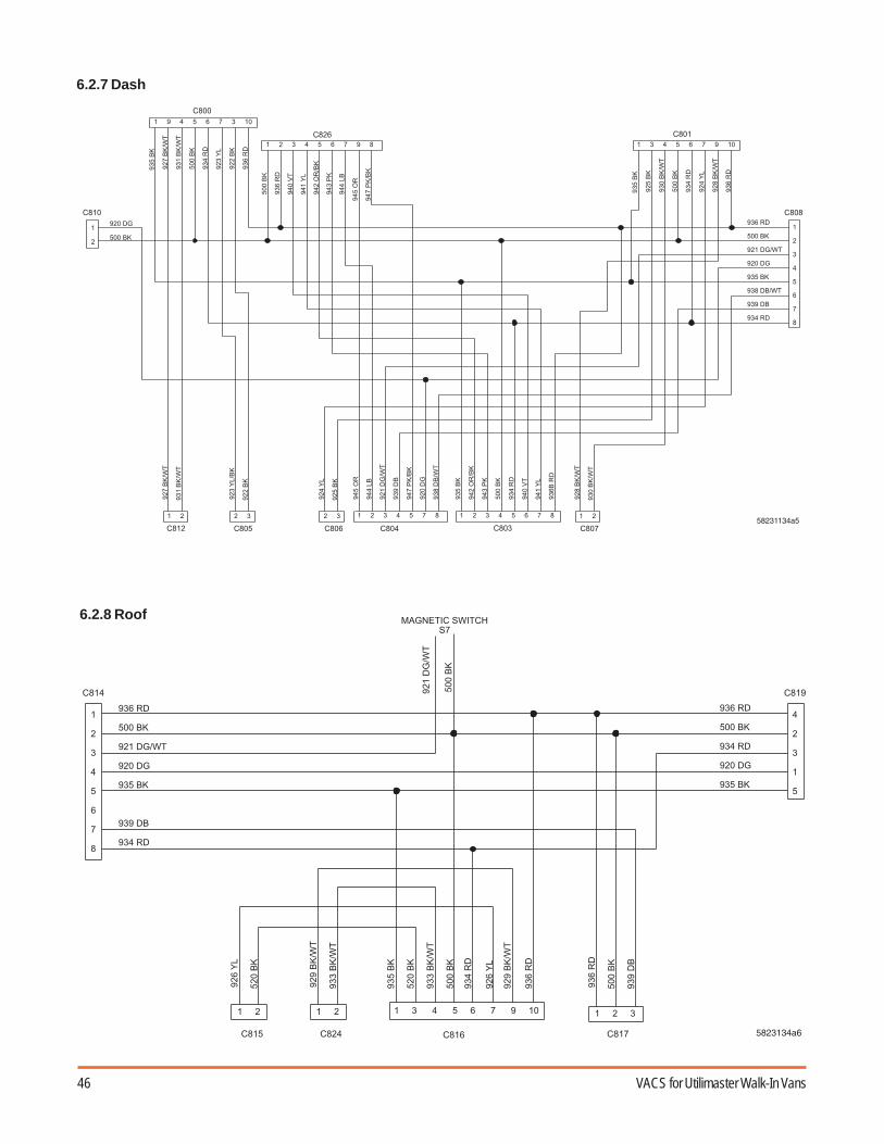
46 VACS for Utilimaster Walk-In Vans
6.2.7 Dash
*
"(
)
"(
)
"
"(
)
"(
)
*
"
)
**
,
,
,
"()
,"()
"(
)
"(
)
"
,"(
)
"
"(
)
"
)
"(
)
"(
)
** *
*
*
*
*
6.2.8 Roof
,"()
,
,
4+,.-)1*0(1)*20
,"(
)
*
*
"(
)
"(
)
*
"(
)
"(
)
*
*
*
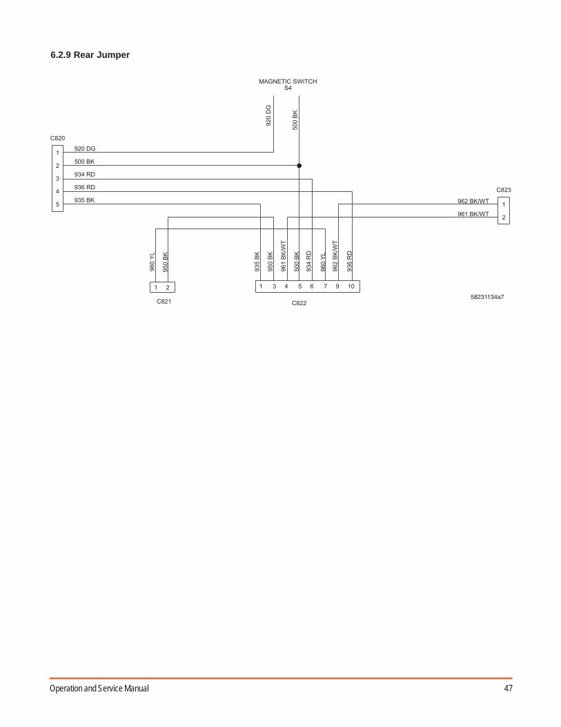
47Operation and Service Manual
6.2.9 Rear Jumper
"()
"()
"(
)
"(
)
4+,.-)1*0(1)*20
,
*
*
*
,
*

48 VACS for Utilimaster Walk-In Vans
6.3 Model Year 2003 and Later
6.3.1 Wiring Diagram Overview
04+,.-)1*0(1)*2
*1,)+1
*-+ +)*2 *
-+4/ -
*0 -.1
*1.)-5+*-
*1.)-5+*-
*4)1.0-.0
* 20(1)*2
* 2
0 -.1*1.)-5+*-
*0 -.1
* -5)5.)4/ -
*1,.2+.1.)-5+*-
* 2 +)*20(1)*2
* 1,.4
*1,2)5)4/ -
*0 -.1
* 1.)-5+*-
04+,.-)1*0(1)*2
04+,.-)1*0(1)*2
04+,.-)1*0(1)*2
04+,.-)1*0(1)*2
* 1.)-5+*-
* 2
4/ -
*0(1)*21,)+1
2.1.)-5+*-
* 1,.2+.1.)-5+*-
*1,.1)1.
1.)-5+*-
*+/81,.)1.
* 0(1.)-5+*-
* *- +0
*2 +)*20(1)*2
2+.-00!/.-)2-2'0/ 1-0(-))2-00)-4
)2--10++45/0-+))2-+/82.8
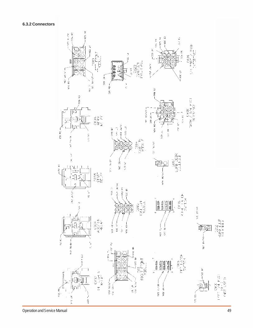
49Operation and Service Manual
6.3.2 Connectors

50 VACS for Utilimaster Walk-In Vans
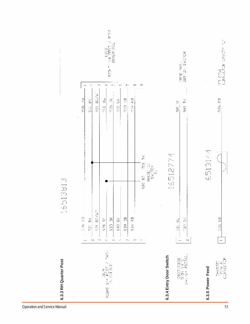
51Operation and Service Manual
6.3.
3 R
H Q
uar
ter
Po
st
6.3.
4 E
ntr
y D
oo
r S
wit
ch
6.3.
5 P
ow
er F
eed
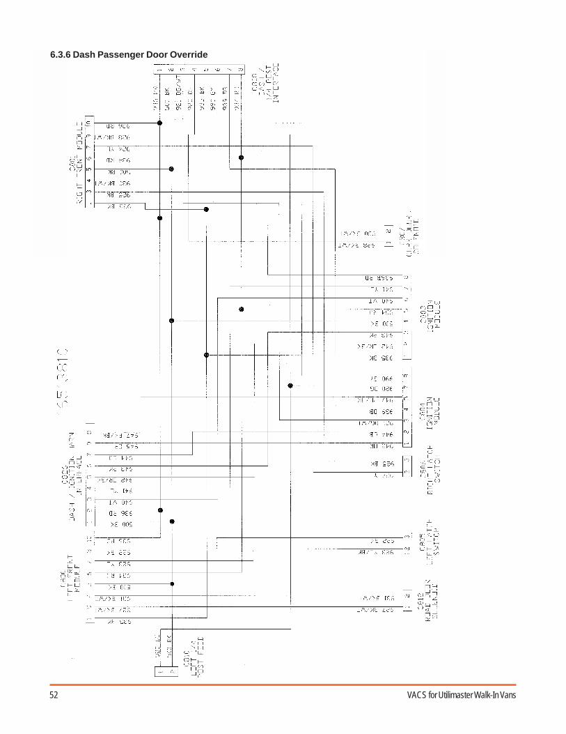
52 VACS for Utilimaster Walk-In Vans
6.3.6 Dash Passenger Door Override

53Operation and Service Manual
6.3.7 Roof
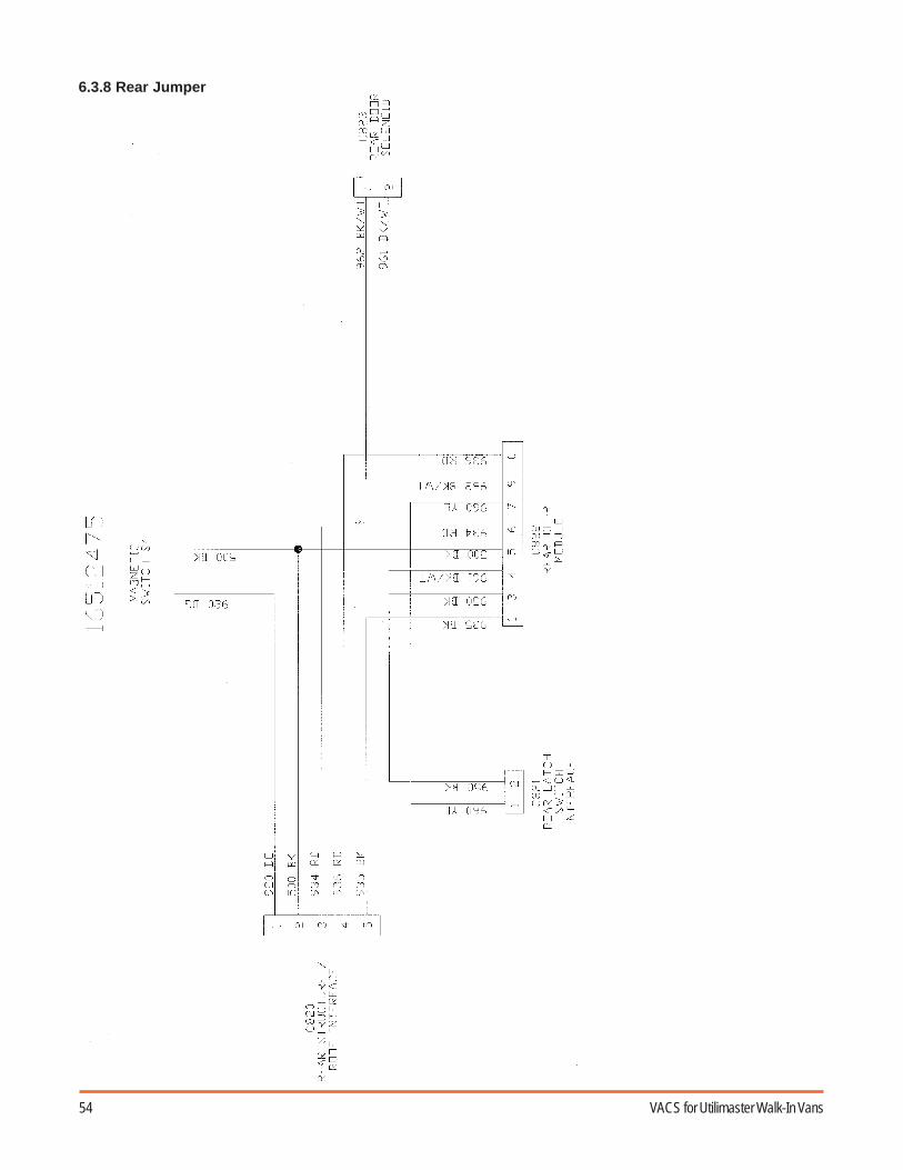
54 VACS for Utilimaster Walk-In Vans
6.3.8 Rear Jumper

55Operation and Service Manual
6.4 Schematic Overview
6.4.1 Model Year 2000–2001
1,.1)1.4/ -
"
*
*
*
*
*
*
"(
)
"(
)
"(
)
"(
)
"(
)
"(
)
"
"(
)
"(
)
**
**
* *
**
*
*
,
,
,"()
"()
,
,"(
)
*
*
*
"(
)
*
*
*
*
*
*
*
*
*
*
*
*
*
*
*
*
*
*
*
*
*
*
*
*
*
*
*
*
*
,
,"(
)
*
*
*
*
*
*
*
*
*+,4)1.
0-.0
*+4)1.
0-.0
1,.1)1.4/ -
4+,.-)1*
0(1)*2
* *
**
4+,.-)1*
0(1)*2
*
*
*
*
*
*
*
*
*
*
*
*
*
*
*
*
*
*
*
*
*
*
*
*
*
*
*
*
*
*
*
*
*
*
*
*
*
*
*
*
*
*
*
*
*
*
*
*
*
*
*
*
*
*
4+,.-)1*
0(1)*2
4+,.-)1*
0(1)*2
/
- -
+0-
0(1)*2
/
4/ -
/
2-+
4/ -
-5)
0 -
.1
-5)4/ -
-5)
- -
+0-
0(1)*2
/
0 -
.1
/
2-+
- -
+0-
0(1)*2
/
2-+
0 -
.1
1,2)
- -
+0-
0(1)*2
1,2)4/ -
1,2)
0 -
.1
! '
!,/.'

56 VACS for Utilimaster Walk-In Vans
"(
)
"(
)
,
,
,"(
)
"
"(
)
"(
)
,
,"(
)
,
,"()
"
"(
)
"(
)
"(
)
"(
)
*
*
*
*
*
*
**
**
* *
**
*
*
*
*
*
*
*
*
*
*
*
*
*
*
*
*
*
*
*
*
*
*
*
*
*
*
*
*
*
*
*
*
*
*
*+,4)1.
0-.0
1,.1)1.4/ -
4+,.-)1*
0(1)*2
* *
**
4+,.-)1*
0(1)*2
*
*
*
*
*
*
*
*
*
*
*
*
*
*
*
*
*
*
*
*
*
*
*
*
*
*
*
*
*
*
*
*
*
*
*
*
*
*
*
*
*
*
*
*
*
*
*
*
*
*
*
*
*
*
4+,.-)1*
0(1)*2
4+,.-)1*
0(1)*2
/
- -
+0-
0(1)*2
/
4/ -
/
2-+
4/ -
-5)
0 -
.1
-5)4/ -
-5)
- -
+0-
0(1)*2
/
0 -
.1
/
2-+
- -
+0-
0(1)*2
/
2-+
0 -
.1
1,2)
- -
+0-
0(1)*2
1,2)4/ -
1,2)
0 -
.1
! "3'
1,.1)1.4/ -
!,/.'
6.4.2 Model Year 2001½–2003

57Operation and Service Manual
6.4.3 Model Year 2003 and Later

58 VACS for Utilimaster Walk-In Vans
6.5 Chassis to Body Wiring Interface
6.5.1 Horn Interface (Freightliner)
6.5.2 Ignition Interface (Freightliner)
58231085 Rev A
-,+!*2+0010'-,+
-!+*0'
-,+
9:
(),+
-,+
-,+!*2+0010'
-,+!+*0'
-,+!*2+0010'
-,+!+*0'
(),+!*2+0010'
(),+!+*0'
-,+
9:
1,.1)1.0(1)*2*..-*).
1,.1)1.0(1)*2*..-*) 4+
1,.1)1.0(1)*2*..-*)4+
-,+
(),+
-,+!.)/0-'
-,+
-,+
, 5 -
*+
()
()
1999 Only
Connectors shown in terminal insertion view
(4) DOVETAIL RELAYS(UNDER DASH)
YELLOWWIRE
CHASSISHARNESS
WHITEWIRE
PINK/BLACKWIRE
VACSHARNESS16512767
PINK/BLACKWIRE
58231084 Rev A

59Operation and Service Manual
6.5.3 Chassis Interface (1999–2001 Freightliner)
*..
"
)
"
"
"
"
"
"
+
5
0)+)- +1,.- ++**- +1.) 1,2)0
(
)
)
(
)
+ +
(
)
(
)
10
2.1.)-5+*-
(+(-+)2-+*5***2+.-00
(1-* 04+)*2
6.5.4 Chassis Interface (2001–2003 Freightliner)
(
)
(
)
(
)
5-*+
1,.1)1.0(1)*2*..-*)
1,.1)1.*..-*)
(
)
(
)
-,5+
,
*..
"
)
"
"
"
"
"
0)+)- +1,.- +1.) 1,2)0
)
+ +
2.1.)-5+*-

60 VACS for Utilimaster Walk-In Vans
6.5.5 Chassis Interface (2003 and Later Freightliner)

61Operation and Service Manual
6.5.6 Chassis Interface (Navistar International)
"(
)
"
"
*..
*..*
*..
*..+
/))0 1*-1,.*..
0*
*..
*..+ +42.
+)-0)1
*..+ +42.(
*..
*..,0)/
8("20
"()
()
+ +
"
()
,
)
"
"
)
-*+
0*2-4+)1*1+,+45
*..*+, ,)0()!*+'
+)-0)1
*..*0(*1*/1)
1.) 1,2)- + +**- + 2.- + 0)+)- + 4-*21,.
VACS WIRES AT POSITIVE BATTERY POSTRed wire = VACS power at battery - 20 Amp FuseOrange wire = VACS alarm horn at battery - 15 Amp FuseVACS current draw > 80 ma AWAKEVACS current draw < 20 ma ASLEEPVACS current draw = 20 ma ASLEEP AND ONE DOOR OPEN

62 VACS for Utilimaster Walk-In Vans
6.6 Circuit Number Identification

63Operation and Service Manual
7.0 Recessing the Rear Access Reader
7.1 Overview
VACS access readers are impact resistant, but they will not withstand the force of a vehicle backing into a dockor other obstacle. To prevent damaging the rear access reader, the reader can be removed and reinstalled intoa recessed position. To remount the rear access reader in a recessed location, order the Recessed RearReader Retrofit Kit (P/N 23002142SK).
7.2 Exploded Parts List
Illustration VA–100 Recessed Reader Kit Parts and Reference Parts
;
; ;;
;
;
;;
-) <) -0*1)1.
-5-5-5-5-5-5
+)-=-*-00--+-4/.)0+*-"7 -./4 ,+0-)=-*-00--+--+-=+**-00 --.)++0*-(" > "*)400(+02-=5 +)?0+-@0+-5(@ )28*" >,@*2*@0*-(? 8"0 )128(25@
021- 0-*/1) ( 0-.)021- /0-*/1) 0-.)
+)./4-
+)-0214-++ /4- -00-.) +)*2 0-.)+5
-5-5
./)" 5.022-800 .5
(+02-"5 +)/00!" '@1.*
2-*4- /,
WARNING: Put the transmission in PARK and set the parking brake before workingon the vehicle.
WARNING: Always wear safety glasses while working on the vehicle.

64 VACS for Utilimaster Walk-In Vans
Illustration VA–105Disconnect Module
7.3 Procedure
NOTE: Read all instructions before beginning. 1. Disconnect the main wire harness to the rear door access
module (aluminum box). Disconnecting this first will protect therest of the system. This is the larger of the two harnesses thatplug into the module. (See Illustration VA–105.)
2. Disconnect the access reader wire harness.
3. Carefully cut the wire ties holding the harnesses together.
4. Disconnect the electrical connection to the rear door solenoidand unhook the wire harness from the taillight cover. (SeeIllustration VA–110.)
5. Remove the one Torx® head screw attaching the taillight cover tothe floor. Retain the screw for reinstallation. (See IllustrationVA–110.)
NOTE: The rear latch solenoid has been removed toclarify these instructions. See Illustration VA–115.
6. Remove the four #10 screws holding the reader in place andremove the reader. Remove the plastic wire grommet from therear structure and retain.
7. Line up the reader plate as shown. (See Illustration VA–120.)
Notice the new reader location will be located below and to theleft of the existing holes! Use the 3/8" diameter bolts to tempo-rarily hold the plate in place using the existing hole. Do nottighten more than finger-tight.
8. Drill four 0.257" diameter (17/64") holes located 1" from edge ofplate. (See Illustration VA–120.)
Illustration VA–110 Remove Cover
0.257" Dia. Holes
Pilot Hole for Hole Saw
Illustration VA–115 Latch Solenoid Illustration VA–120 Reader Plate
CAUTION: This step is going to use the recessedreader mounting plate as a drill fixture. Please readtwice and drill once!

65Operation and Service Manual
9. Drill the center hole to the same diameter as the guidedrill of your hole saw. (See Illustrations VA–120 andVA–125.)
10. Remove the plate.
11. Use a hole saw to drill a 4" diameter hole in the rearstructure. (See Illustration VA–125.)
12. Deburr the hole to remove sharp edges. (SeeIllustration VA–130.)
13. Thoroughly clean the interior surface of the rear wall.
14. Peel off the paper from the back of the gasket andinstall it on the inside of rear structure. Be very carefulto line up the center hole and mounting holes. (SeeIllustration VA–135.)
15. Install 1/4-20 stainless screws, and then install 3/4"long spacers. (See Illustration VA–135.)
16. Install the plastic wire grommet on the reader mountingplate. (See Illustration VA–140.)
17. Attach the reader to the plate using 4 screws removedearlier. Torque to 10 to 15 in•lb.
18. Install the plate with the reader attached to the rearstructure. (See Illustration VA–145.) Tighten the
Illustration VA–125 Drill 4" Hole
Illustration VA–130Deburr Opening
Illustration VA–135Gasket with Spacers
Illustration VA–140Feed Harness with Grommet Illustration VA–145
Attach Mounting Plate
CAUTION: Use a quality hole saw because thehole diameter is important to good sealing.

66 VACS for Utilimaster Walk-In Vans
1/4-20 nuts until the spacers bottom out. Do notover tighten. (Torque to 4 lb•ft.)
19. Use metal shears or a saber saw to notch thetaillight cover. The notch is 1" deep, extending 4"below solenoid notch and 1" above solenoidnotch. (See Illustration VA–150.)
20. Reinstall the taillight cover using the same fastener.(See Illustration VA–155.)
21. Reconnect the access reader harness.
22. Reconnect the control module harness.
23. Secure the wires to their original positions withwire ties.
24. Install dome plugs from the exterior. (SeeIllustration VA–160.)
25. Follow the standard paint repair procedure totouch up the paint around the reader. (SeeIllustration VA–165.) Refer to Utilimaster BodyService Manual.
Illustration VA–150Notch Light Cover
Illustration VA–155Install Light Cover
Illustration VA–160Install Dome Plugs
Illustration VA–165Recessed Access Reader Completed
CAUTION: Make sure wires do not get pinchedand that they are fastened securely.

67Operation and Service Manual
8.0 Assembly Drawings
8.1 Side Door
(1-2+.-00
(1-2+.-00
'+00-4 4/0)*4 (1)25400
)</--) 0- 5)2-+1.,5+0)-.-0))1. 0. ' ,+-)(--.4+,.-)60-.0!-)'10-<A'+ 14-.01.0)/)01-/. -00)2-(10-0-*151-
/)01-4)-+-(11.,,-0)2/,2-)/021.,/ -/))02(+)6 *+)1.
+
0)1- +)-6./) +)-+00
-)+1 +
(+02-=?5 +)
+)*2=1,2)2+.
)=" 8"2-8*+0*-(=" 8200(+02-= +1."(+02-= *"0*-(=? 80 )2-820*-(*+ +*8"0*-(=?81 )001-)= +1.+00./) 0)1-0+*-1..-
+00./) 0)1-0+*-/)- +)-=0)1-+0-
/021.,="/021.,="
--0(1)*264+,.-)+., -=4),4+,01- 0-.)
+))1) -<)
-) +).
202(. 201)-
1.0)+ +)*22 0-.)
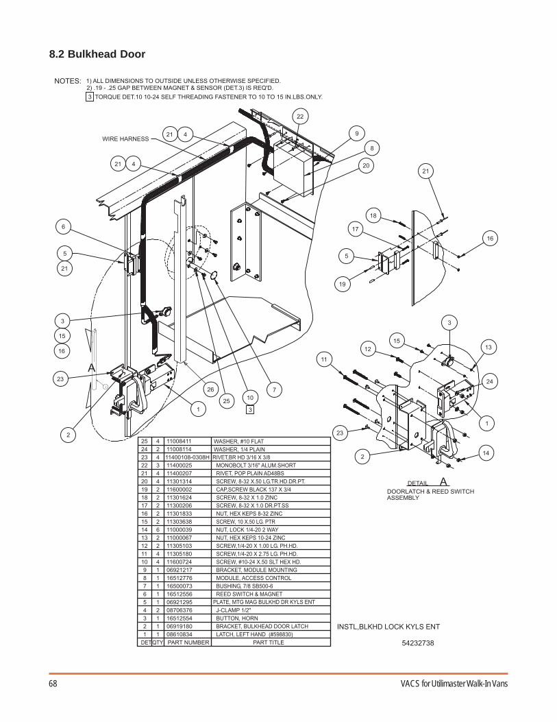
68 VACS for Utilimaster Walk-In Vans
8.2 Bulkhead Door
1.0) = 2 * 0-.)
+)*26--0(1)*2+00-4
-)+1 +
+
)</--) 0- 5)2-+1.,5+0)-.-))1. 0.
' ,+-)(--.4+,.-)60-.0!-)'10-<A'+ 14-.01.0)/)01-/. -00)2-(10-0-*151-.)-0B
(1-2+.-00
0*-(=8 ,)*)40@
./)=2-8-0 @1.*
0*-(=" 8 ,22
1-)=2"8"+.+ 2
./)=2-8-0 @1.*
./)= *" (+
0*-(= 8)00
0*-(=" 8 ,22
(+02-=?5 +) (+02-=" +1.
4. )"7+ /402)1-)= +1.+00*-(= 8 ,)2)*+=0*-( +*8"0*-(= 8@1.*
/)).=2.
0*-(=? 80 )2-82+*-)=4/ -4/.)1.,4/ -=+**-00*.) /021.,="0 --0(1)*264+,.-)? (
+)-=4),4+,/ 2 0-.)C * +4"7
+*-)=/ 2-+ +)*2 +)*2= -5)2+.!?'
+)./4- +))1) -<)
-)

69Operation and Service Manual
8.3 Rear Door
(+02-=" *! '4 (@
+., -=+-1+>7
021- =/-0-*/1)-+
./)0-)+" +(
021- = (-0-*/1)-+
-)
<) +))1) -+)./4-
+)*2=-+ +*-)=-+4/ - 4/ -=+**-00*.) +)-=0214+ 0-.) /)).=2. --=0(1)*264+,.-)? (
02+5)=-+ *
)=2-8*+" 8,@ (+02-=" +1. ./)= *" (+
0*-(= 8)00 1-)=+-8="8"
0 1-)=2"8"+.+
0*-(=? 8)@
C * +4"7
*+=0*-( +*8"1-)= +1.+0
0)+= +0)1* +*7
0+*- *=* ("-+ ? -+
1.0) * 0-.)
+
*.-5/.1)-+*/01-
+C+0(1)*2-810)1.,
(1-2+.-00
0(1)*2)2-+-1.0)+ +)1.54+,.-)1*
.)-0B '+ 14-.01.0)/)01-/. -00)2-(10-0-*151-
,+-)(--.4+,.-)60-.0!-)'10-<A
-)+1 +
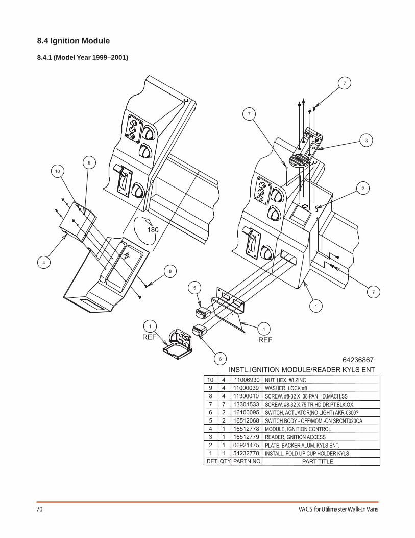
70 VACS for Utilimaster Walk-In Vans
8.4 Ignition Module
8.4.1 (Model Year 1999–2001)
-5 -5
1.0) 1,.1)1.4/ -"-+- 0-.)
-+-=1,.1)1.+**-004/ -=1,.1)1.*.)
1.0)+ =5 /*/2 - 0
./)=2-8?@1.*(+02-= *?0*-(=? 8+.24+*2000*-(=? 8)2) 80(1)*2=+*)/+)!. 1,2)'+ D
+)-=+*-+ /4 0-.)
0(1)*2 55"44 .0*.)*+
+))1) -<)
-) +)..

71Operation and Service Manual
8.4 Ignition Module
8.4.2 (Model Year May 2001–2003)
-)<)+)./4- -0*1)1.
*-=1.0)/4-.)+.- +00*-(=" 8 "(+02-.-."8"0*-(= 8"0*-(" 8)8./)(- " (+02-="5 +)./)=" *(+
1-)= +*(+02-=.-."8"0*-(=" 8"+., -=0215)-0/)
+00=1.0)+.- +*0/)=0)+))-*4/ -./)? -+*-=+02 /-+*-=+02 (-
),, -. 10-.,("+0
+00=1.0)+.- !2EFG'
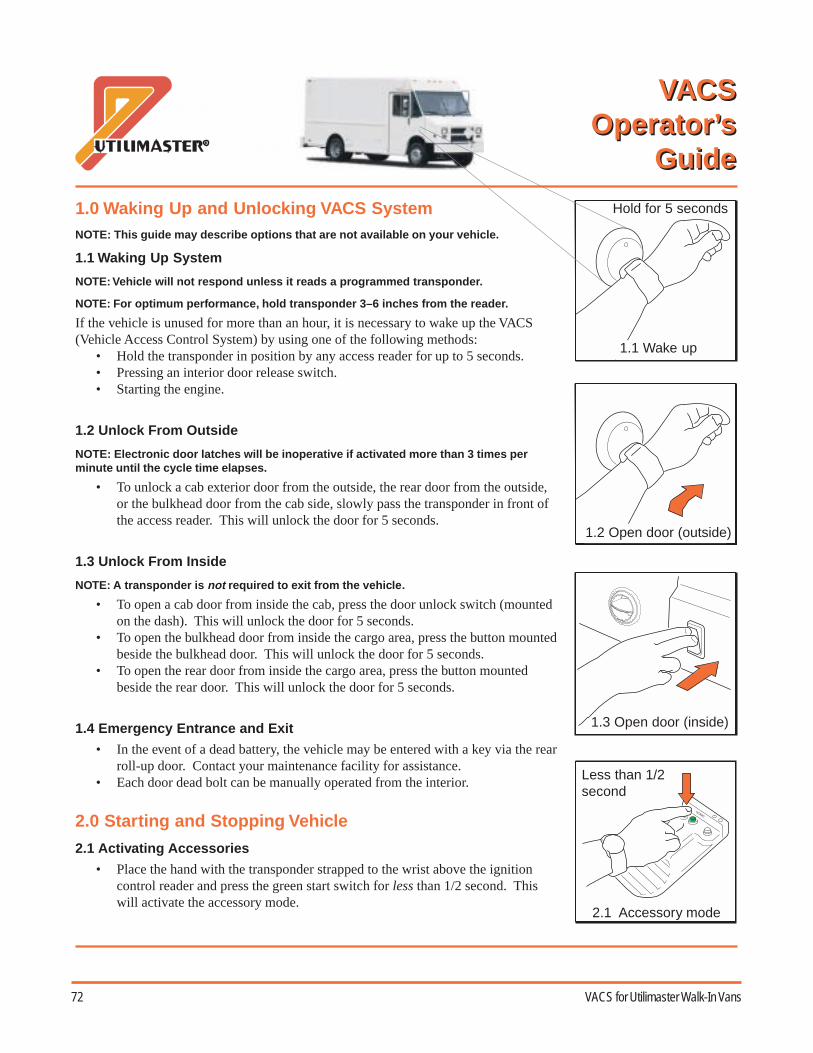
72 VACS for Utilimaster Walk-In Vans
AppendixesVACS Operator's Guide
1.1 Wake up
VACSOperator’s
Guide
2.0 Starting and Stopping Vehicle
2.1 Activating Accessories
• Place the hand with the transponder strapped to the wrist above the ignitioncontrol reader and press the green start switch for less than 1/2 second. Thiswill activate the accessory mode.
1.0 Waking Up and Unlocking VACS SystemNOTE: This guide may describe options that are not available on your vehicle.
1.1 Waking Up System
NOTE: Vehicle will not respond unless it reads a programmed transponder.
NOTE: For optimum performance, hold transponder 3–6 inches from the reader.
If the vehicle is unused for more than an hour, it is necessary to wake up the VACS(Vehicle Access Control System) by using one of the following methods:
• Hold the transponder in position by any access reader for up to 5 seconds.• Pressing an interior door release switch.• Starting the engine.
1.2 Unlock From Outside
NOTE: Electronic door latches will be inoperative if activated more than 3 times perminute until the cycle time elapses.
• To unlock a cab exterior door from the outside, the rear door from the outside,or the bulkhead door from the cab side, slowly pass the transponder in front ofthe access reader. This will unlock the door for 5 seconds.
1.3 Unlock From Inside
NOTE: A transponder is not required to exit from the vehicle.
• To open a cab door from inside the cab, press the door unlock switch (mountedon the dash). This will unlock the door for 5 seconds.
• To open the bulkhead door from inside the cargo area, press the button mountedbeside the bulkhead door. This will unlock the door for 5 seconds.
• To open the rear door from inside the cargo area, press the button mountedbeside the rear door. This will unlock the door for 5 seconds.
1.4 Emergency Entrance and Exit
• In the event of a dead battery, the vehicle may be entered with a key via the rearroll-up door. Contact your maintenance facility for assistance.
• Each door dead bolt can be manually operated from the interior.
Less than 1/2second
2.1 Accessory mode
1.3 Open door (inside)
1.2 Open door (outside)
Hold for 5 seconds
VACSOperator’s
Guide

73Operation and Service Manual
VACS Operator’s Guide (Part Number 03102240) Revision C
©2003, Utilimaster.® Rev. C, printed Aug 2003 in U.S.A. Utilimaster Corporation, 65906 State Road 19, P.O. Box 585, Wakarusa, Indiana, 46573–0585.
2.2 Starting Engine
NOTE: All doors must be closed (including bulkhead)to start vehicle in normal operation. If a door is ajar, ared LED on the ignition reader will flash whenattempting to start the unit.
• On gas engines, place hand with the transpon-der above ignition control reader, and pressthe green start switch until engine starts.
• On diesel engines, place hand with the tran-sponder above ignition control reader, andpress the green start switch for less than 1/2 second or until the instrumentpanel lights turn on. After the “Wait to Start” light goes off, press the greenstart switch until engine starts.
NOTE: You have 10 seconds after the start switch is released to try and restart thevehicle. If this time has expired, the red stop switch has to be pressed, and then thegreen start switch has to be pressed again to start the engine.
2.3 Stopping Engine
NOTE: No transponder is needed to shut off the engine.
• Press the red stop switch for more than 1/4 second. The engine will stop,and the interior lights will activate for 10 seconds.
3.0 Vehicle Security
3.1 Operating Modes
NOTE: If the alarm is disarmed/deactivated and the vehicle is not started or inaccessory mode, the system will arm itself after 10 seconds.
VACS has two operating modes. To toggle between modes (while in accessorymode or when engine is running), press the black mode button.
• Door Opened (Red LED): The security system will be armed 10 secondsafter any exterior door is opened.
• Door Closed (Yellow LED): The security system will be armed 10 secondsafter all exterior doors are closed.
3.2 Disarming/Deactivating the Alarm
The alarm can be deactivated by any one of the following methods:• A valid transponder is read by any access reader.• Starting the vehicle with a valid transponder.
For additional information, browse www.utilimaster.com/vacs. From there, the Vehicle AccessControls System Operation and Service Manual (Part Number 03102103) can be downloaded inAdobe Acrobat format. Also, a (paper) copy can be ordered by emailing [email protected],calling 800–237–7806 (574–862–3219), or faxing 574–862–7637.
ST ART
Disarm alarm3.2 Disarm alarm
Close all doors2.2 Close all doors
Door closed
3.1 Operating modes
Door open
2.2 Start engine
2.3 Stop engine
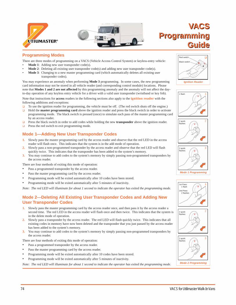
74 VACS for Utilimaster Walk-In Vans
VACS Programming Guide VACSProgramming
Guide
Mode 1—Adding New User Transponder Codes1. Slowly pass the master programming card by the access reader and observe that the red LED in the access
reader will flash once. This indicates that the system is in the add mode of operation.2. Slowly pass a non-programmed transponder by the access reader and observe that the red LED will flash
quickly twice. This indicates that the transponder has been added to the system’s memory.3. You may continue to add codes to the system’s memory by simply passing non-programmed transponders by
the access reader.
There are four methods of exiting this mode of operation:• Pass a programmed transponder by the access reader.
• Pass the master programming card by the access reader.
• Programming mode will be exited automatically after 10 codes have been stored.
• Programming mode will be exited automatically after 5 minutes of inactivity.
Note: The red LED will illuminate for about 1 second to indicate the operator has exited the programming mode.
Mode 2—Deleting All Existing User Transponder Codes and Adding NewUser Transponder Codes1. Slowly pass the master programming card by the access reader once, and then pass it by the access reader a
second time. The red LED in the access reader will flash once and then twice. This indicates that the system isin the delete mode of operation.
2. Slowly pass a transponder by the access reader. The red LED will flash quickly twice. This indicates that allexisting codes in memory have now been deleted and the transponder that you just passed by the access readerhas been added to the system’s memory.
3. You may continue to add codes to the system’s memory by simply passing non-programmed transponders bythe access reader.
There are four methods of exiting this mode of operation:• Pass a programmed transponder by the access reader.
• Pass the master programming card by the access reader.
• Programming mode will be exited automatically after 10 codes have been stored.
• Programming mode will be exited automatically after 5 minutes of inactivity.
Note: The red LED will illuminate for about 1 second to indicate the operator has exited the programming mode.
11st Pass: 1 flash
2nd Pass: 2 flashes
Mode 1 Programming
Mode 2 Programming
Ignition Reader
3
Red switch
Black switch
1 flash
2 quickflashes
2
1
2 quickflashes
2
3
2 quickflashes
2 quickflashes
Programming ModesThere are three modes of programming on a VACS (Vehicle Access Control System) or keyless-entry vehicle:• Mode 1: Adding new user transponder code(s).• Mode 2: Deleting all existing user transponder code(s) and adding new user transponder code(s).• Mode 3: Changing to a new master programming card (which automatically deletes all existing user
transponder codes).
You may experience an anomaly when performing Mode 3 programming. In some cases, the new programmingcard information may not be stored in all vehicle reader (and corresponding control module) locations. Pleasenote that Modes 1 and 2 are not affected by this programming anomaly and the anomaly will not affect the day-to-day operation of any keyless entry vehicle for a driver with a valid user transponder (wristband or key fob).
Note that instructions for access readers in the following sections also apply to the ignition reader with thefollowing additions and exceptions: To use the ignition reader for programming, the vehicle must be off. (The red switch shuts off the engine.) Hold the master programming card above the ignition reader and press the black switch in order to activate
programming mode. The black switch is pressed (once) to simulate each pass of the master programming cardby an access reader.
Press the black switch in order to add codes while holding the new transponder above the ignition reader. Press the red switch to exit programming mode.
VACSProgramming
Guide
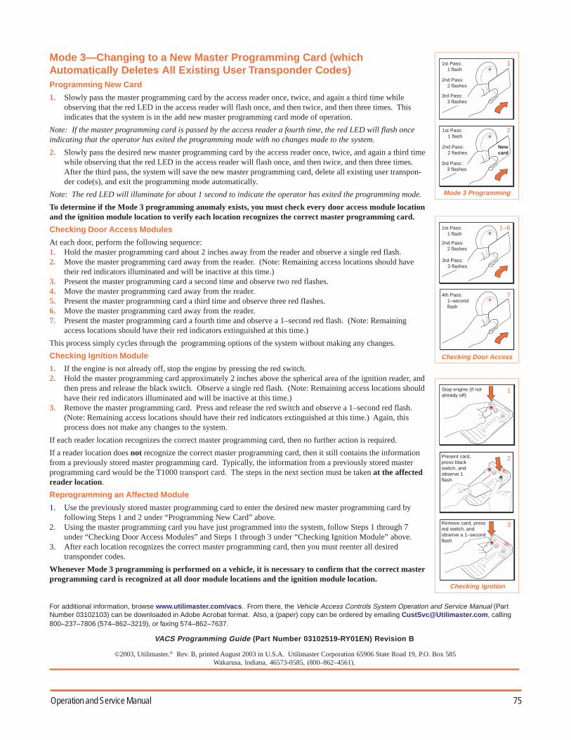
75Operation and Service Manual
STOP
Mode 3—Changing to a New Master Programming Card (whichAutomatically Deletes All Existing User Transponder Codes)Programming New Card
1. Slowly pass the master programming card by the access reader once, twice, and again a third time whileobserving that the red LED in the access reader will flash once, and then twice, and then three times. Thisindicates that the system is in the add new master programming card mode of operation.
Note: If the master programming card is passed by the access reader a fourth time, the red LED will flash onceindicating that the operator has exited the programming mode with no changes made to the system.
2. Slowly pass the desired new master programming card by the access reader once, twice, and again a third timewhile observing that the red LED in the access reader will flash once, and then twice, and then three times.After the third pass, the system will save the new master programming card, delete all existing user transpon-der code(s), and exit the programming mode automatically.
Note: The red LED will illuminate for about 1 second to indicate the operator has exited the programming mode.
To determine if the Mode 3 programming anomaly exists, you must check every door access module locationand the ignition module location to verify each location recognizes the correct master programming card.
Checking Door Access Modules
At each door, perform the following sequence:1. Hold the master programming card about 2 inches away from the reader and observe a single red flash.2. Move the master programming card away from the reader. (Note: Remaining access locations should have
their red indicators illuminated and will be inactive at this time.)3. Present the master programming card a second time and observe two red flashes.4. Move the master programming card away from the reader.5. Present the master programming card a third time and observe three red flashes.6. Move the master programming card away from the reader.7. Present the master programming card a fourth time and observe a 1–second red flash. (Note: Remaining
access locations should have their red indicators extinguished at this time.)
This process simply cycles through the programming options of the system without making any changes.
Checking Ignition Module
1. If the engine is not already off, stop the engine by pressing the red switch.2. Hold the master programming card approximately 2 inches above the spherical area of the ignition reader, and
then press and release the black switch. Observe a single red flash. (Note: Remaining access locations shouldhave their red indicators illuminated and will be inactive at this time.)
3. Remove the master programming card. Press and release the red switch and observe a 1–second red flash.(Note: Remaining access locations should have their red indicators extinguished at this time.) Again, thisprocess does not make any changes to the system.
If each reader location recognizes the correct master programming card, then no further action is required.
If a reader location does not recognize the correct master programming card, then it still contains the informationfrom a previously stored master programming card. Typically, the information from a previously stored masterprogramming card would be the T1000 transport card. The steps in the next section must be taken at the affectedreader location.
Reprogramming an Affected Module
1. Use the previously stored master programming card to enter the desired new master programming card byfollowing Steps 1 and 2 under “Programming New Card” above.
2. Using the master programming card you have just programmed into the system, follow Steps 1 through 7under “Checking Door Access Modules” and Steps 1 through 3 under “Checking Ignition Module” above.
3. After each location recognizes the correct master programming card, then you must reenter all desiredtransponder codes.
Whenever Mode 3 programming is performed on a vehicle, it is necessary to confirm that the correct masterprogramming card is recognized at all door module locations and the ignition module location.
For additional information, browse www.utilimaster.com/vacs. From there, the Vehicle Access Controls System Operation and Service Manual (PartNumber 03102103) can be downloaded in Adobe Acrobat format. Also, a (paper) copy can be ordered by emailing [email protected], calling800–237–7806 (574–862–3219), or faxing 574–862–7637.
©2003, Utilimaster.® Rev. B, printed August 2003 in U.S.A. Utilimaster Corporation 65906 State Road 19, P.O. Box 585Wakarusa, Indiana, 46573-0585, (800–862–4561).
Mode 3 Programming
Checking Door Access
Checking Ignition
VACS Programming Guide (Part Number 03102519-RY01EN) Revision B
11st Pass: 1 flash
2nd Pass: 2 flashes
2
3rd Pass: 3 flashes
Newcard
1st Pass: 1 flash
2nd Pass: 2 flashes
3rd Pass: 3 flashes
1st Pass: 1 flash
2nd Pass: 2 flashes
3rd Pass: 3 flashes
74th Pass: 1–second flash
1–6
STOP
1Stop engine (if notalready off)
2
Remove card, pressred switch, andobserve a 1–secondflash
Present card,press blackswitch, andobserve 1flash
3

76 VACS for Utilimaster Walk-In Vans
Filing Warranty ClaimsIf a problem on the Utilimaster body is caused by adefect in materials or workmanship during the warrantyperiod, it will be covered by our Limited Warranty.Chassis, engine, tires, and battery failures are coveredby the individual manufacturers.
Claims must meet the requirements listed below.Failure to meet these requirements may result in adenied or delayed claim.
Complete a repair order with the followinginformation:
• Chassis VIN or Utilimaster Body SerialNumber.
• Year and model of vehicle.• Owner’s and/or service facility’s name and
complete address.• Service center representative’s signature
(or name).• Date vehicle was repaired.• Mileage at time of failure.• Itemized description of the problem, includ-
ing complaint, cause of failure (if known),and correction (describe in detail).
• Service center labor rate and total time ofrepair.
• Total claim amount, including cost of parts(include Utilimaster P/Ns), labor, miscella-neous charges, and sales tax (if applicable).
• Your claim or repair order number.
NOTE: The claim or repair ordernumber is the number used tomatch Utilimaster payment withthe work done. It will be noted onyour payment.
• Utilimaster authorization number (repairscosting over $150 U.S. or for structural war-ranty require prior authorization fromUtilimaster).
Other claim requirements:• Any repairs over $150 U.S. or for structural
warranty require prior authorization fromUtilimaster, and that number must appear on therepair order. Contact the Warranty Department.
• Any claim that is not legible and complete willbe returned for completion.
• All paint claims require pictures, estimates, andprior authorization.
• Shipping damage claims also require pictures,estimates, and prior authorization. The damagemust also be noted on the Delivery Acceptanceform. This form requires the signature of thecarrier driver.
• Sublet work must have the sublet repair orderattached to the service facility’s repair order thatis being submitted.
• Claims must be submitted within 30 days afterthe repair is completed.
The claim can be mailed, faxed, emailed, orperformed on-line on our web site (assuming allrequired information is included).
• Warranty claims should be mailed to:UtilimasterAttn: Warranty Department65528 State Road 19P.O. Box 585Wakarusa, IN 46573-0585U.S.A.
• Alternately, you can fax your claim (if no photo-graphs are involved) with the above informationto 574-862-7637. (The resolution of thereceived copies must be acceptable, or you willbe asked to mail your hard copies.)
• Or you can email your claim with the aboveinformation to [email protected].(You can download a customizable WarrantyClaim Form template from the Utilimaster website www.utilimaster.com. The template has aheader that you can customize with your nameand address. Then, to file a claim, you only haveto enter the specific information about thevehicle—saving retyping the same addressinformation repeatedly. After completing theform information, the file can be emailed as anattachment. This form can also be used formailing or faxing.)

77Operation and Service Manual
WARNING: Unauthorized alteration or improper maintenance or repair can result in possibledangerous driving conditions.
CAUTION: Utilimaster vehicles are built to designed specifications. Improper use oroverloading can cause damage to the equipment and void the warranty.
Claims are paid semimonthly. Utilimaster generally does not pay sales tax on claims. If you do not have our taxexemption number on file, please call 800-582-3454 or 574-862-4561 and ask for the accounting departmentto obtain the number.
Before returning any parts, contact a Utilimaster Warranty representative.
Ordering PartsHow to Order
To order parts for this vehicle, gather thefollowing information:
• Model and year of vehicle (200_ Aeromasteron _____ chassis).
• Chassis VIN or Utilimaster Body Number• Complete shipping address• Preferred method of shipping• Complete description of all the necessary
parts (see the Part Numbers section in thismanual or the relevant Utilimaster Body partsmanual)
• Method of payment
NOTE: Customer Service preferspayment by Visa, MasterCard,Discover, or American Expresscredit cards. Purchase Orders fromcustomers with established openaccounts are also accepted.
Then contact Utilimaster Customer Service byusing one of the following methods:
• Email your order [email protected]. (See theCustomizable Parts Order Form section.)
• Fax your order to 574-862-7637.• Call 800-237-7806 (574-862-3219) and ask
for the Parts Department.• Mail or express service your order to the
following address:Utilimaster Corp.Attn: Parts Department65528 State Road 19P.O. Box 585Wakarusa, IN 46573-0585U.S.A.
Returns
To return parts for credit, call the Customer ServiceDepartment for prior authorization. All returns must beshipped prepaid freight. A restocking fee will be chargedto all returns. Special-order parts are not returnable.
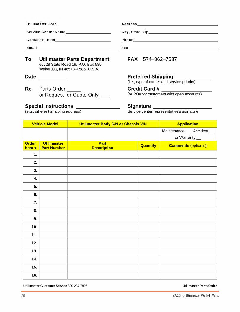
78 VACS for Utilimaster Walk-In Vans
To Utilimaster Parts Department 65528 State Road 19, P.O. Box 585 Wakarusa, IN 46573–0585, U.S.A.
FAX 574–862–7637
Date Preferred Shipping (i.e., type of carrier and service priority)
Re Parts Order or Request for Quote Only
Credit Card # (or PO# for customers with open accounts)
Special Instructions (e.g., different shipping address)
Signature Service center representative's signature
Vehicle Model Utilimaster Body S/N or Chassis VIN Application
Maintenance __ Accident __
or Warranty __
Order Item #
Utilimaster Part Number
Part Description Quantity Comments (optional)
1.
2.
3.
4.
5.
6.
7.
8.
9.
10.
11.
12.
13.
14.
15.
16.
Utilimaster Customer Service 800-237-7806 Utilimaster Parts Order
Utilimaster Corp. Service Center Nam e Contact Person Email
Address City, State, Zip Phone Fax
Parts Order Form

79Operation and Service Manual
Reporting Safety DefectsUnited States Only
If you believe that your vehicle has a defect that couldcause a crash, injury, or death, you should immedi-ately inform the National Highway Traffic SafetyAdministration (NHTSA), in addition to notifyingUtilimaster.
If NHTSA receives similar complaints, it may open aninvestigation, and if it finds that a safety defect existsin a group of vehicles, it may order a recall andremedy campaign. However, NHTSA cannotbecome involved in individual problems between you,your dealer, or Utilimaster.
To contact NHTSA, you may either call the Auto SafetyHotline toll-free at 800-424-9393 (or 202-366-0123 inthe Washington, D.C., area) or write to:
NHTSAU.S. Department of Transportation400 Seventh StreetWashington, DC 20590
You can also obtain other information about motorvehicle safety from the Hotline.
Canada Only
If you believe that your Canadian-registered vehiclehas a defect that could cause a crash, injury, or death,you should immediately inform Transport Canada, inaddition to notifying Utilimaster.
To contact Transport Canada, call 800-333-0510 (or613-993-9851 in the Ottawa region) or write to:
Transport CanadaMotor Vehicle Defect InvestigationPO Box 8880Ottawa, Ontario, K1G 3J2
Towing and Emergency Repairs
Problems with the Utilimaster body are unlikely todisable a vehicle enough to make it undrivable. Seethe chassis operator’s manual and the engineservice manual for emergency information.
See the chassis operator’s manual for informa-tion on towing procedures. Utilimaster recom-mends the following:
• A wheel lift or flatbed equipment is thepreferred method of towing.
• Unload the vehicle when possible to reducestress on the chassis during towing.
• Be sure to place the transmission in Neutraland fully release the parking brake if towing.

80 VACS for Utilimaster Walk-In Vans
More InformationDownload Files
Many support documents, including those described here, are downloadable (asAdobe® Acrobat® PDF files) from our award-winning web site atwww.utilimaster.com. Click on the Technical Manuals button, to access thedownload page. To view the files you must have the Adobe Acrobat Readerversion 4.0 or higher installed on your computer. Acrobat readers are availablefree for all leading computer operating systems on the Adobe web site(www.adobe.com).
Utilimaster Quick Reference Parts Guide
Easily find commonly replaced parts for most Utilimaster vehicles in the UtilimasterQuick Reference Parts Guide. This illustrated document includes part numbers fordoor hardware, electrical components, mirrors, vents, mud flaps, roll-up door parts,and many other parts. It also includes sealants and repair kits.
Utilimaster Detailed Parts and Wiring Manuals
Find wiring diagrams and parts specific to Aeromaster bodies in detailed parts manualsand wiring manuals.
Contact Utilimaster
Browse our site for more information about Utilimaster and its products orcontact Utilimaster Customer Service by using one of the followingmethods:• Call 800-237-7806 (or 574-862-3219).• Fax to 574-862-7637.• Email to [email protected].• Mail to the following address:
UtilimasterAttn: Customer Service Department65528 State Road 19P.O. Box 585Wakarusa, IN 46573-0585U.S.A.
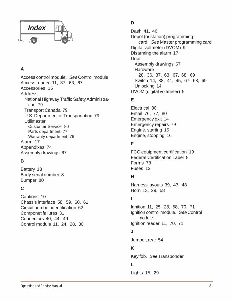
81Operation and Service Manual
A
Access control module. See Control moduleAccess reader 11, 37, 63, 67Accessories 15Address
National Highway Traffic Safety Administra-tion 79
Transport Canada 79U.S. Department of Transportation 79Utilimaster
Customer Service 80Parts department 77Warranty department 76
Alarm 17Appendixes 74Assembly drawings 67
B
Battery 13Body serial number 8Bumper 80
C
Cautions 10Chassis interface 58, 59, 60, 61Circuit number identification 62Componet failures 31Connectors 40, 44, 49Control module 11, 24, 28, 30
D
Dash 41, 46Depot (or station) programming
card. See Master programming cardDigital voltmeter (DVOM) 9Disarming the alarm 17Door
Assembly drawings 67Hardware
28, 36, 37, 63, 67, 68, 69Switch 14, 38, 41, 45, 67, 68, 69Unlocking 14
DVOM (digital voltmeter) 9
E
Electrical 80Email 76, 77, 80Emergency exit 14Emergency repairs 79Engine, starting 15Engine, stopping 16
F
FCC equipment certification 19Federal Certification Label 8Forms 78Fuses 13
H
Harness layouts 39, 43, 48Horn 13, 29, 58
I
Ignition 11, 25, 28, 58, 70, 71Ignition control module. See Control
moduleIgnition reader 11, 70, 71
J
Jumper, rear 54
K
Key fob. See Transponder
L
Lights 15, 29
Index

82 VACS for Utilimaster Walk-In Vans
M
Maintenance and service 36, 37Master programming card 12, 24, 30, 33Memory saver 9Motion sensor 29, 30
N
Notes 10Notices 3Numbers
Body serial number 8Part 11Phone 76, 77, 79, 80VIN 8Work order 8
Numbers, circuit identification 62
O
Operation (VACS) 14Override switch 52
P
PartsAssembly 67Guide 80Numbers 11Ordering 77, 78Return 77
Passenger door 52Phone numbers
NHTSA 79Transport Canada 79Utilimaster Customer Service 77, 80Warranty claims (fax) 76
Power feed 45Program card. See Master programming
cardProgramming 11, 17, 74Programming Guide, VACS 74
Q
Quarter post 41, 45, 51
R
Return parts 77Revision 3Roof 42, 46, 53
S
SafetyConsiderations 10Defects, reporting 79
Security modes 16Serial number, body 8Service 36, 37Starting the engine 15Station (or depot) programming card. See
Master programming cardStopping the alarm 17Stopping the engine 15, 16
T
T1000 transport card. See Master pro-gramming card
Terminal extraction tool 9Terminal tool kit 9Tools 9Torque wrench 9Towing 79Transponder 11, 14, 17, 74Troubleshooting 19
U
Unlocking, doors 14Utilimaster body serial number 8Utilimaster Customer Service 76, 77, 80Utilimaster Quick Reference Parts Guide
80
V
VACS Programming Guide 74Vehicle Access Control System (VACS)
defined 14VIN 8

83Operation and Service Manual
W
Waking up system 14Warnings 10Warranty claims 76Web site 3, 76, 80Wire diagrams 39, 43, 58Work order number 9Wristband. See Transponder

84 VACS for Utilimaster Walk-In Vans
Notes

85Operation and Service Manual

86 VACS for Utilimaster Walk-In Vans
VV VVVAA AAA
CS
fC
S f
CS
fC
S f
CS
for U
tilima
ster
or U
tilima
ster
or U
tilima
ster
or U
tilima
ster
or U
tilima
ster A
er
Ae
rA
er
Ae
rA
ero
ma
ster
om
aste
r o
ma
ster
om
aste
r o
ma
ster VV VVV
an
sa
ns
an
sa
ns
an
s
©©©©©Utilimaster CorUtilimaster CorUtilimaster CorUtilimaster CorUtilimaster Corporporporporporaaaaation,tion,tion,tion,tion, 65906 Sta 65906 Sta 65906 Sta 65906 Sta 65906 State Rte Rte Rte Rte Road 19,oad 19,oad 19,oad 19,oad 19, P P P P P.O.O.O.O.O..... Bo Bo Bo Bo Box 585x 585x 585x 585x 585Wakarusa, Indiana, 46573–0585, USAWakarusa, Indiana, 46573–0585, USAWakarusa, Indiana, 46573–0585, USAWakarusa, Indiana, 46573–0585, USAWakarusa, Indiana, 46573–0585, USA
PPPPPararararart Numbert Numbert Numbert Numbert Number::::: 03102103 03102103 03102103 03102103 03102103Revision ERevision ERevision ERevision ERevision E
Op
er
Op
er
Op
er
Op
er
Op
eraa aaa
tion
an
d S
er
tion
an
d S
er
tion
an
d S
er
tion
an
d S
er
tion
an
d S
ervic
e M
an
vice
Ma
nvic
e M
an
vice
Ma
nvic
e M
an
ua
l (Ru
al (R
ua
l (Ru
al (R
ua
l (Ree eee
vv vvv.. ... E)
E)
E)
E)
E)