vector mechanics for engineers: 2 staticsarahim/skmm1203 statics of particle.pdf · •...
TRANSCRIPT
VECTOR MECHANICS FOR ENGINEERS:
STATICS
Eighth Edition
Ferdinand P. Beer
E. Russell Johnston, Jr.
Lecture Notes:
J. Walt Oler
Texas Tech University
CHAPTER
© 2007 The McGraw-Hill Companies, Inc. All rights reserved.
2Statics of Particles
© 2007 The McGraw-Hill Companies, Inc. All rights reserved.
Vector Mechanics for Engineers: Statics
Eig
hth
Ed
ition
2 - 2
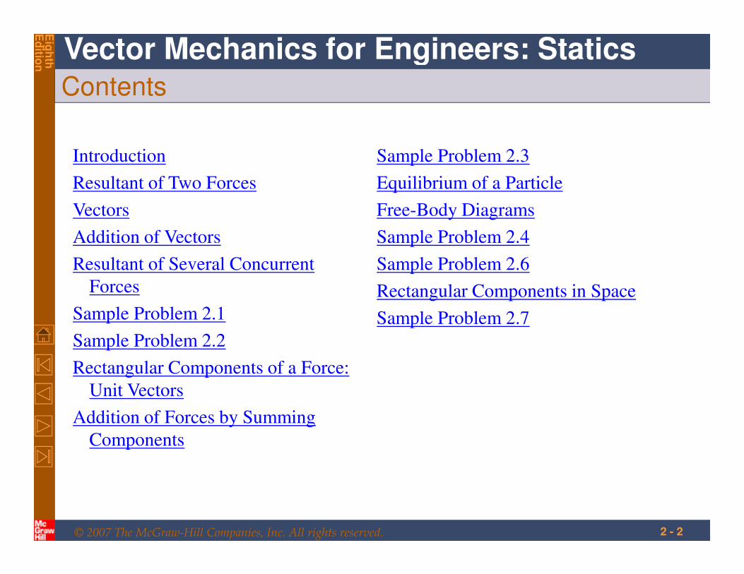
Contents
Introduction
Resultant of Two Forces
Vectors
Addition of Vectors
Resultant of Several Concurrent
Forces
Sample Problem 2.1
Sample Problem 2.2
Rectangular Components of a Force:
Unit Vectors
Addition of Forces by Summing
Components
Sample Problem 2.3
Equilibrium of a Particle
Free-Body Diagrams
Sample Problem 2.4
Sample Problem 2.6
Rectangular Components in Space
Sample Problem 2.7
© 2007 The McGraw-Hill Companies, Inc. All rights reserved.
Vector Mechanics for Engineers: Statics
Eig
hth
Ed
ition
2 - 3
Introduction
• The objective for the current chapter is to investigate the effects of forces
on particles:
- replacing multiple forces acting on a particle with a single
equivalent or resultant force,
- relations between forces acting on a particle that is in a
state of equilibrium.
• The focus on particles does not imply a restriction to miniscule bodies.
Rather, the study is restricted to analyses in which the size and shape of
the bodies is not significant so that all forces may be assumed to be
applied at a single point.
© 2007 The McGraw-Hill Companies, Inc. All rights reserved.
Vector Mechanics for Engineers: Statics
Eig
hth
Ed
ition
2 - 4
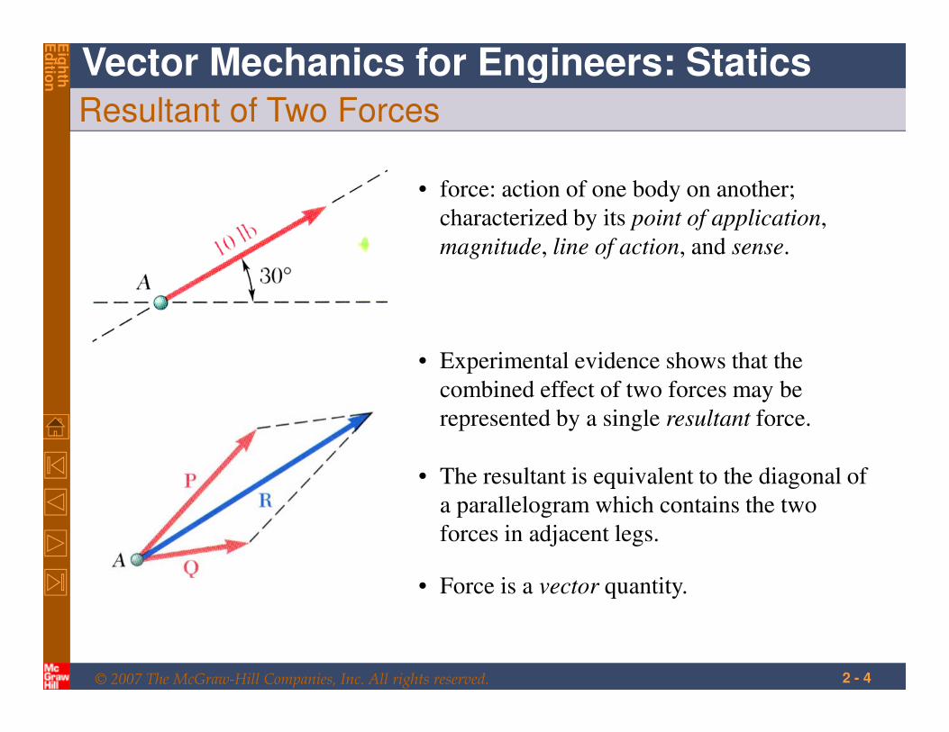
Resultant of Two Forces
• force: action of one body on another;
characterized by its point of application,
magnitude, line of action, and sense.
• Experimental evidence shows that the
combined effect of two forces may be
represented by a single resultant force.
• The resultant is equivalent to the diagonal of
a parallelogram which contains the two
forces in adjacent legs.
• Force is a vector quantity.
© 2007 The McGraw-Hill Companies, Inc. All rights reserved.
Vector Mechanics for Engineers: Statics
Eig
hth
Ed
ition
2 - 5
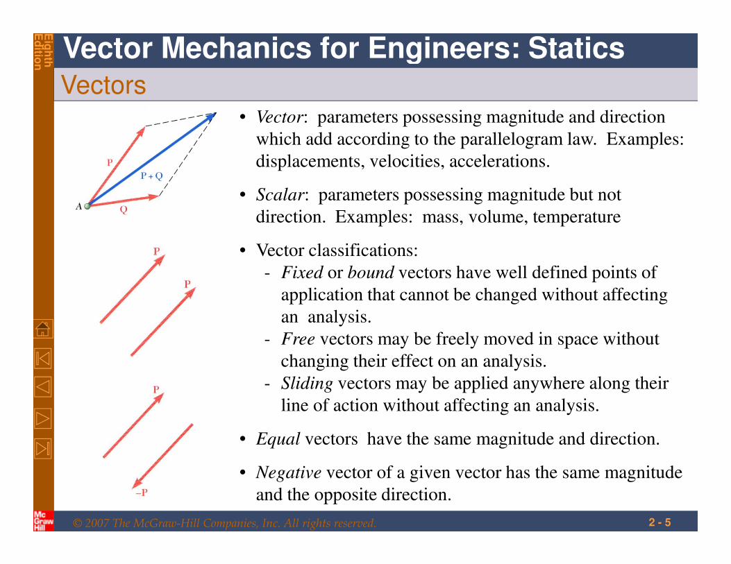
Vectors• Vector: parameters possessing magnitude and direction
which add according to the parallelogram law. Examples:
displacements, velocities, accelerations.
• Vector classifications:
- Fixed or bound vectors have well defined points of
application that cannot be changed without affecting
an analysis.
- Free vectors may be freely moved in space without
changing their effect on an analysis.
- Sliding vectors may be applied anywhere along their
line of action without affecting an analysis.
• Equal vectors have the same magnitude and direction.
• Negative vector of a given vector has the same magnitude
and the opposite direction.
• Scalar: parameters possessing magnitude but not
direction. Examples: mass, volume, temperature
© 2007 The McGraw-Hill Companies, Inc. All rights reserved.
Vector Mechanics for Engineers: Statics
Eig
hth
Ed
ition
2 - 6
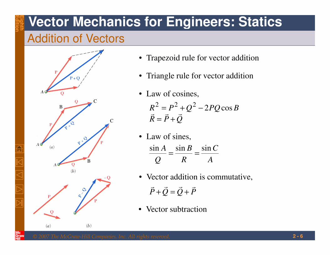
Addition of Vectors
• Trapezoid rule for vector addition
• Triangle rule for vector addition
B
B
C
C
QPR
BPQQPRrrr
+=
−+= cos2222
• Law of cosines,
• Law of sines,
A
C
R
B
Q
A sinsinsin==
• Vector addition is commutative,
PQQPrrrr
+=+
• Vector subtraction
© 2007 The McGraw-Hill Companies, Inc. All rights reserved.
Vector Mechanics for Engineers: Statics
Eig
hth
Ed
ition
2 - 7
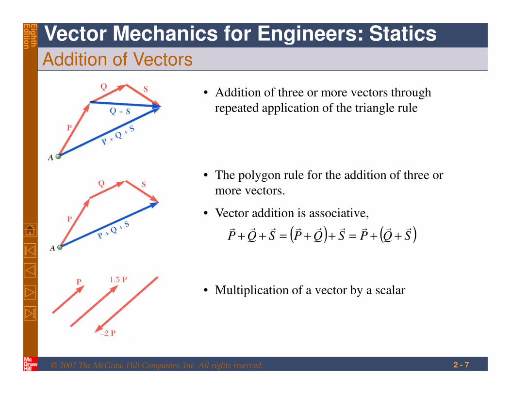
Addition of Vectors
• Addition of three or more vectors through
repeated application of the triangle rule
• The polygon rule for the addition of three or
more vectors.
• Vector addition is associative,
( ) ( )SQPSQPSQPrrrrrrrrr
++=++=++
• Multiplication of a vector by a scalar
© 2007 The McGraw-Hill Companies, Inc. All rights reserved.
Vector Mechanics for Engineers: Statics
Eig
hth
Ed
ition
2 - 8
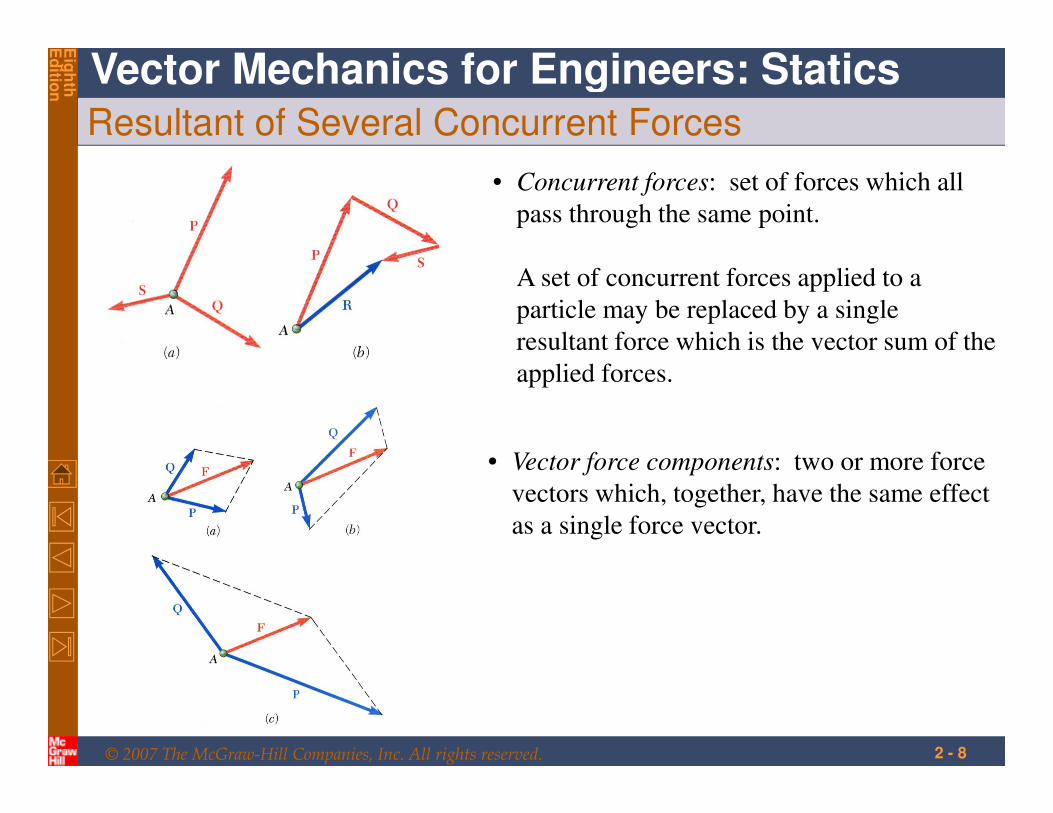
Resultant of Several Concurrent Forces
• Concurrent forces: set of forces which all
pass through the same point.
A set of concurrent forces applied to a
particle may be replaced by a single
resultant force which is the vector sum of the
applied forces.
• Vector force components: two or more force
vectors which, together, have the same effect
as a single force vector.
© 2007 The McGraw-Hill Companies, Inc. All rights reserved.
Vector Mechanics for Engineers: Statics
Eig
hth
Ed
ition
2 - 9
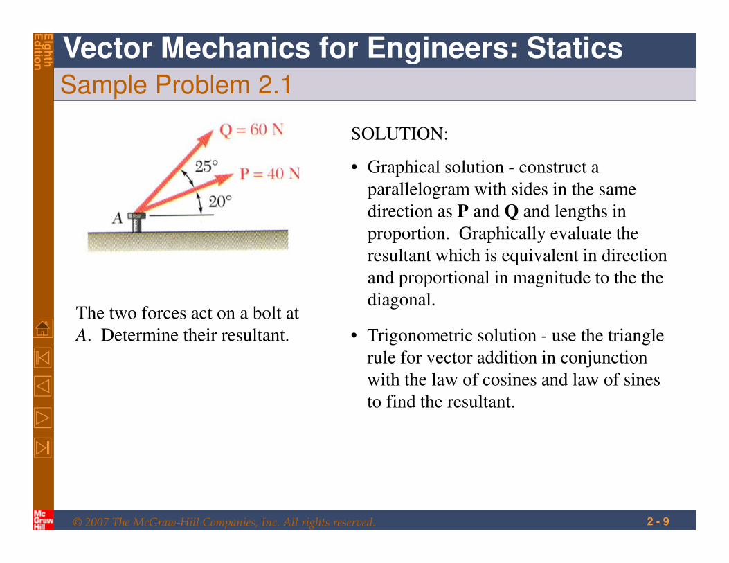
Sample Problem 2.1
The two forces act on a bolt at
A. Determine their resultant.
SOLUTION:
• Graphical solution - construct a
parallelogram with sides in the same
direction as P and Q and lengths in
proportion. Graphically evaluate the
resultant which is equivalent in direction
and proportional in magnitude to the the
diagonal.
• Trigonometric solution - use the triangle
rule for vector addition in conjunction
with the law of cosines and law of sines
to find the resultant.
© 2007 The McGraw-Hill Companies, Inc. All rights reserved.
Vector Mechanics for Engineers: Statics
Eig
hth
Ed
ition
2 - 10
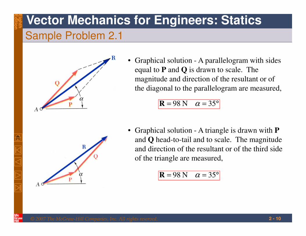
Sample Problem 2.1
• Graphical solution - A parallelogram with sides
equal to P and Q is drawn to scale. The
magnitude and direction of the resultant or of
the diagonal to the parallelogram are measured,
°== 35N 98 αR
• Graphical solution - A triangle is drawn with P
and Q head-to-tail and to scale. The magnitude
and direction of the resultant or of the third side
of the triangle are measured,
°== 35N 98 αR
© 2007 The McGraw-Hill Companies, Inc. All rights reserved.
Vector Mechanics for Engineers: Statics
Eig
hth
Ed
ition
2 - 11
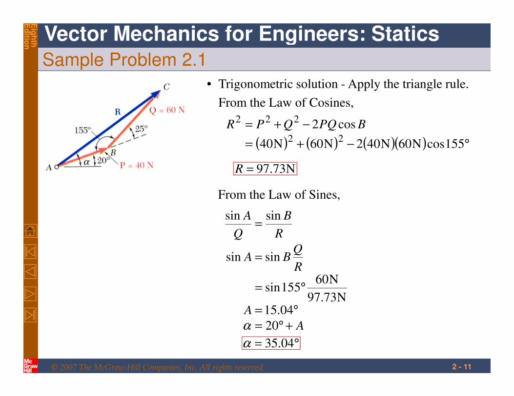
Sample Problem 2.1
• Trigonometric solution - Apply the triangle rule.
From the Law of Cosines,
( ) ( ) ( )( ) °−+=
−+=
155cosN60N402N60N40
cos222
222BPQQPR
A
A
R
QBA
R
B
Q
A
+°=°=
°=
=
=
20
04.15N73.97
N60155sin
sinsin
sinsin
α
N73.97=R
From the Law of Sines,
°= 04.35α
© 2007 The McGraw-Hill Companies, Inc. All rights reserved.
Vector Mechanics for Engineers: Statics
Eig
hth
Ed
ition
2 - 12
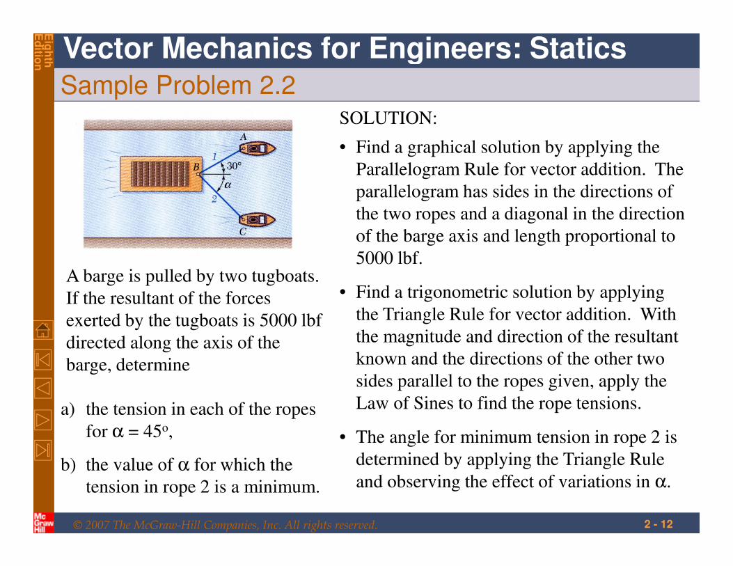
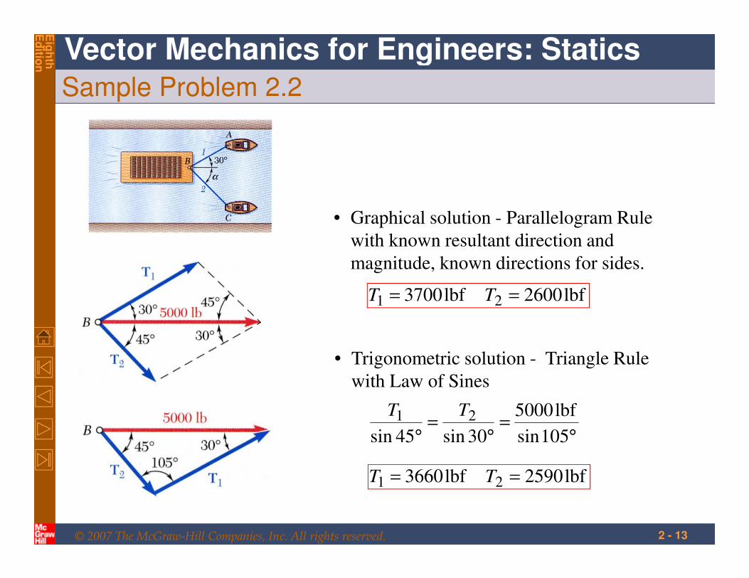
Sample Problem 2.2
a) the tension in each of the ropes
for α = 45o,
b) the value of α for which the
tension in rope 2 is a minimum.
A barge is pulled by two tugboats.
If the resultant of the forces
exerted by the tugboats is 5000 lbf
directed along the axis of the
barge, determine
SOLUTION:
• Find a graphical solution by applying the
Parallelogram Rule for vector addition. The
parallelogram has sides in the directions of
the two ropes and a diagonal in the direction
of the barge axis and length proportional to
5000 lbf.
• The angle for minimum tension in rope 2 is
determined by applying the Triangle Rule
and observing the effect of variations in α.
• Find a trigonometric solution by applying
the Triangle Rule for vector addition. With
the magnitude and direction of the resultant
known and the directions of the other two
sides parallel to the ropes given, apply the
Law of Sines to find the rope tensions.
© 2007 The McGraw-Hill Companies, Inc. All rights reserved.
Vector Mechanics for Engineers: Statics
Eig
hth
Ed
ition
2 - 13
Sample Problem 2.2
• Graphical solution - Parallelogram Rule
with known resultant direction and
magnitude, known directions for sides.
lbf2600lbf3700 21 == TT
• Trigonometric solution - Triangle Rule
with Law of Sines
°=
°=
° 105sin
lbf5000
30sin45sin
21 TT
lbf2590lbf3660 21 == TT
© 2007 The McGraw-Hill Companies, Inc. All rights reserved.
Vector Mechanics for Engineers: Statics
Eig
hth
Ed
ition
2 - 14
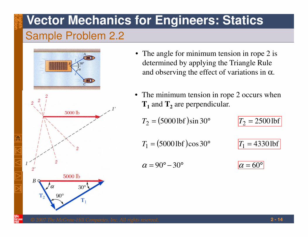
Sample Problem 2.2
• The angle for minimum tension in rope 2 is
determined by applying the Triangle Rule
and observing the effect of variations in α.
• The minimum tension in rope 2 occurs when
T1 and T2 are perpendicular.
( ) °= 30sinlbf50002T lbf25002 =T
( ) °= 30coslbf50001T lbf43301 =T
°−°= 3090α °= 60α
© 2007 The McGraw-Hill Companies, Inc. All rights reserved.
Vector Mechanics for Engineers: Statics
Eig
hth
Ed
ition
2 - 15
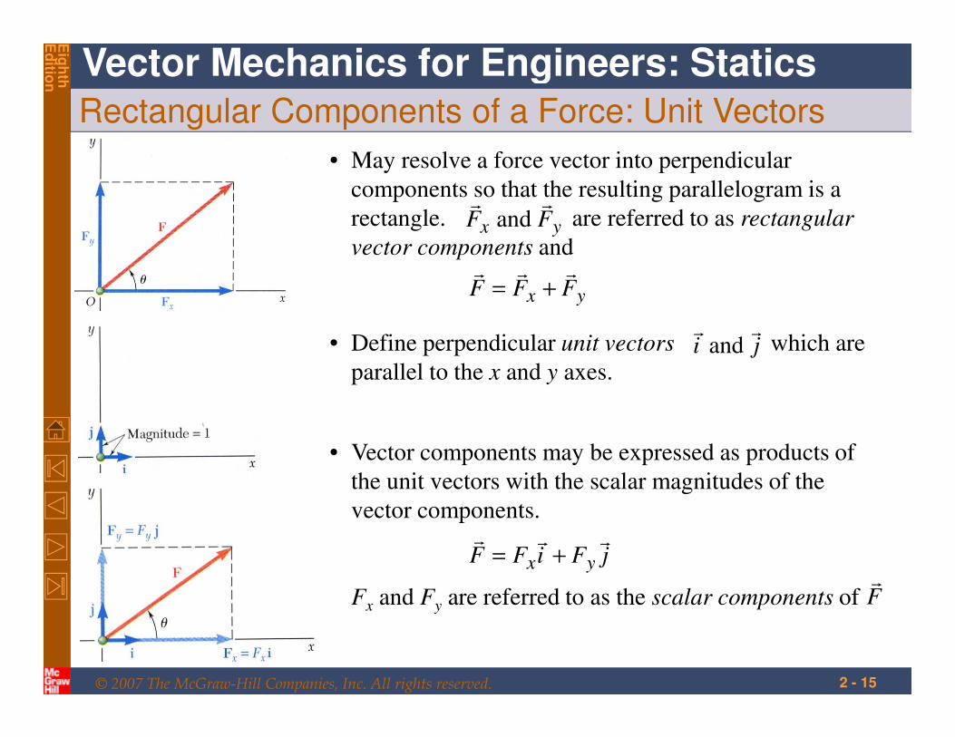
Rectangular Components of a Force: Unit Vectors
• Vector components may be expressed as products of
the unit vectors with the scalar magnitudes of the
vector components.
Fx and Fy are referred to as the scalar components of
jFiFF yx
rrr+=
Fr
• May resolve a force vector into perpendicular
components so that the resulting parallelogram is a
rectangle. are referred to as rectangular
vector components and
yx FFFrrr
+=
yx FFrr
and
• Define perpendicular unit vectors which are
parallel to the x and y axes.jirr
and
© 2007 The McGraw-Hill Companies, Inc. All rights reserved.
Vector Mechanics for Engineers: Statics
Eig
hth
Ed
ition
2 - 16
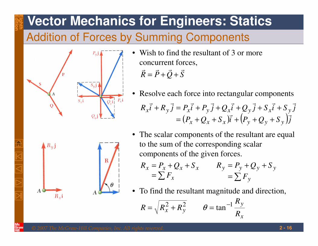
Addition of Forces by Summing Components
SQPRrrrr
++=
• Wish to find the resultant of 3 or more
concurrent forces,
( ) ( ) jSQPiSQP
jSiSjQiQjPiPjRiR
yyyxxx
yxyxyxyxrr
rrrrrrrr
+++++=
+++++=+
• Resolve each force into rectangular components
∑=
++=
x
xxxx
F
SQPR
• The scalar components of the resultant are equal
to the sum of the corresponding scalar
components of the given forces.
∑=
++=
y
yyyy
F
SQPR
x
yyx
R
RRRR
122 tan−=+= θ
• To find the resultant magnitude and direction,
© 2007 The McGraw-Hill Companies, Inc. All rights reserved.
Vector Mechanics for Engineers: Statics
Eig
hth
Ed
ition
2 - 17
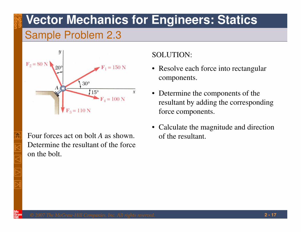
Sample Problem 2.3
Four forces act on bolt A as shown.
Determine the resultant of the force
on the bolt.
SOLUTION:
• Resolve each force into rectangular
components.
• Calculate the magnitude and direction
of the resultant.
• Determine the components of the
resultant by adding the corresponding
force components.
© 2007 The McGraw-Hill Companies, Inc. All rights reserved.
Vector Mechanics for Engineers: Statics
Eig
hth
Ed
ition
2 - 18
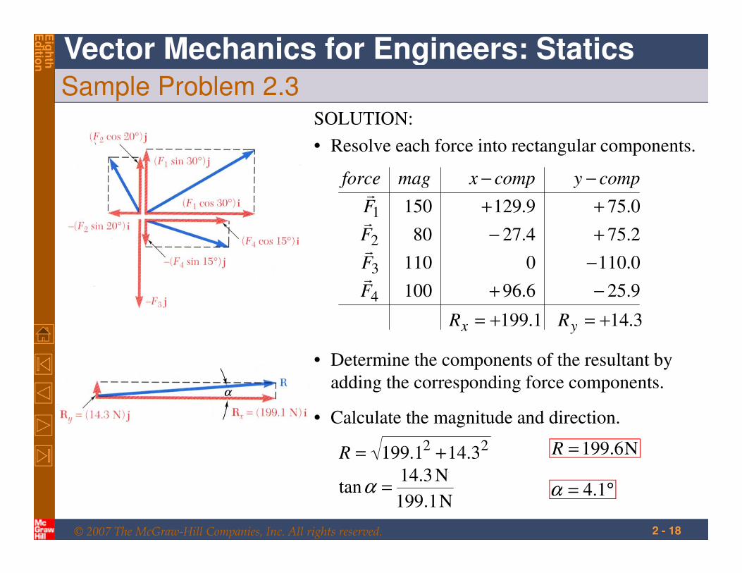
Sample Problem 2.3SOLUTION:
• Resolve each force into rectangular components.
9.256.96100
0.1100110
2.754.2780
0.759.129150
4
3
2
1
−+
−
+−
++
−−
F
F
F
F
compycompxmagforce
r
r
r
r
22 3.141.199 +=R N6.199=R
• Calculate the magnitude and direction.
N1.199
N3.14tan =α °= 1.4α
• Determine the components of the resultant by
adding the corresponding force components.
1.199+=xR 3.14+=yR
© 2007 The McGraw-Hill Companies, Inc. All rights reserved.
Vector Mechanics for Engineers: Statics
Eig
hth
Ed
ition
2 - 19
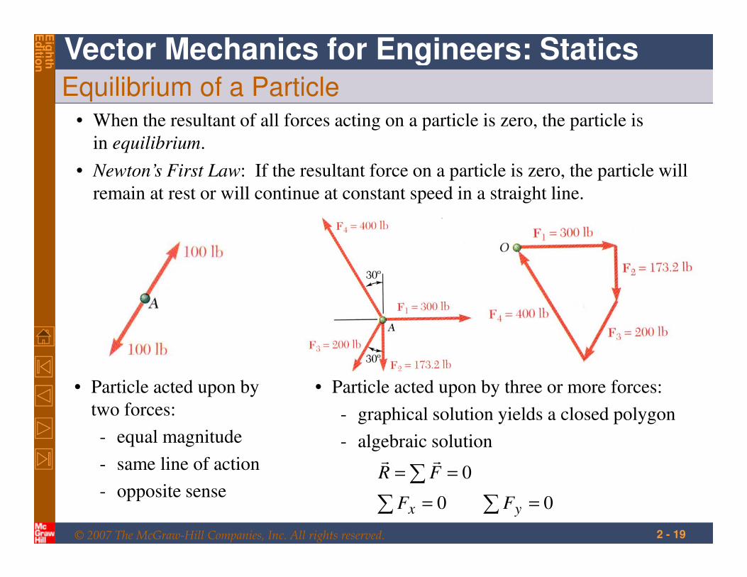
Equilibrium of a Particle• When the resultant of all forces acting on a particle is zero, the particle is
in equilibrium.
• Particle acted upon by
two forces:
- equal magnitude
- same line of action
- opposite sense
• Particle acted upon by three or more forces:
- graphical solution yields a closed polygon
- algebraic solution
00
0
==
==
∑∑
∑
yx FF
FRrr
• Newton’s First Law: If the resultant force on a particle is zero, the particle will
remain at rest or will continue at constant speed in a straight line.
© 2007 The McGraw-Hill Companies, Inc. All rights reserved.
Vector Mechanics for Engineers: Statics
Eig
hth
Ed
ition
2 - 20
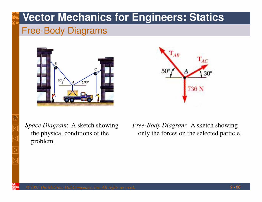
Free-Body Diagrams
Space Diagram: A sketch showing
the physical conditions of the
problem.
Free-Body Diagram: A sketch showing
only the forces on the selected particle.
© 2007 The McGraw-Hill Companies, Inc. All rights reserved.
Vector Mechanics for Engineers: Statics
Eig
hth
Ed
ition
2 - 21
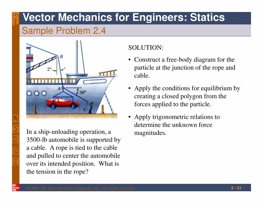
Sample Problem 2.4
In a ship-unloading operation, a
3500-lb automobile is supported by
a cable. A rope is tied to the cable
and pulled to center the automobile
over its intended position. What is
the tension in the rope?
SOLUTION:
• Construct a free-body diagram for the
particle at the junction of the rope and
cable.
• Apply the conditions for equilibrium by
creating a closed polygon from the
forces applied to the particle.
• Apply trigonometric relations to
determine the unknown force
magnitudes.
© 2007 The McGraw-Hill Companies, Inc. All rights reserved.
Vector Mechanics for Engineers: Statics
Eig
hth
Ed
ition
2 - 22
Sample Problem 2.4
SOLUTION:
• Construct a free-body diagram for the
particle at A.
• Apply the conditions for equilibrium.
• Solve for the unknown force magnitudes.
°=
°=
° 58sin
lb3500
2sin120sin
ACAB TT
lb3570=ABT
lb144=ACT
© 2007 The McGraw-Hill Companies, Inc. All rights reserved.
Vector Mechanics for Engineers: Statics
Eig
hth
Ed
ition
2 - 23
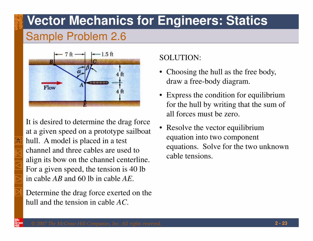
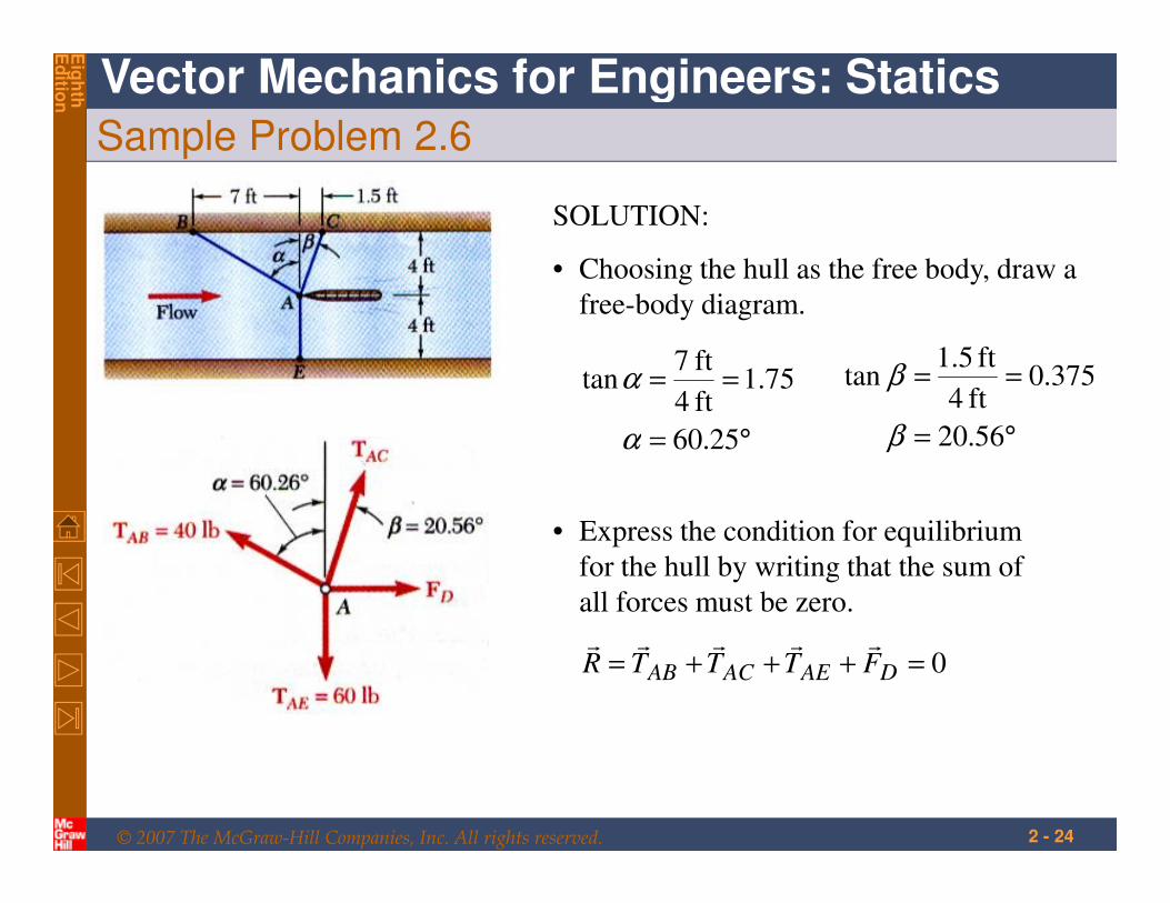
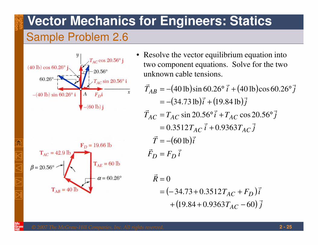
Sample Problem 2.6
It is desired to determine the drag force
at a given speed on a prototype sailboat
hull. A model is placed in a test
channel and three cables are used to
align its bow on the channel centerline.
For a given speed, the tension is 40 lb
in cable AB and 60 lb in cable AE.
Determine the drag force exerted on the
hull and the tension in cable AC.
SOLUTION:
• Choosing the hull as the free body,
draw a free-body diagram.
• Express the condition for equilibrium
for the hull by writing that the sum of
all forces must be zero.
• Resolve the vector equilibrium
equation into two component
equations. Solve for the two unknown
cable tensions.
© 2007 The McGraw-Hill Companies, Inc. All rights reserved.
Vector Mechanics for Engineers: Statics
Eig
hth
Ed
ition
2 - 24
Sample Problem 2.6
SOLUTION:
• Choosing the hull as the free body, draw a
free-body diagram.
°=
==
25.60
75.1ft 4
ft 7tan
α
α
°=
==
56.20
375.0ft 4
ft 1.5tan
β
β
• Express the condition for equilibrium
for the hull by writing that the sum of
all forces must be zero.
0=+++= DAEACAB FTTTRrrrrr
© 2007 The McGraw-Hill Companies, Inc. All rights reserved.
Vector Mechanics for Engineers: Statics
Eig
hth
Ed
ition
2 - 25
Sample Problem 2.6
• Resolve the vector equilibrium equation into
two component equations. Solve for the two
unknown cable tensions.
( ) ( )
( ) ( )
( )
( )
( ) jT
iFT
R
iFF
iT
jTiT
jTiTT
ji
jiT
AC
DAC
DD
ACAC
ACACAC
AB
r
r
r
rr
rr
rr
rrr
rr
rrr
609363.084.19
3512.073.34
0
lb 06
9363.03512.0
56.20cos56.20sin
lb 84.19lb 73.34
26.60coslb 4026.60sinlb 40
−++
++−=
=
=
−=
+=
°+°=
+−=
°+°−=
© 2007 The McGraw-Hill Companies, Inc. All rights reserved.
Vector Mechanics for Engineers: Statics
Eig
hth
Ed
ition
2 - 26
Sample Problem 2.6
( )
( ) jT
iFT
R
AC
DACr
r
r
609363.084.19
3512.073.34
0
−++
++−=
=
This equation is satisfied only if each component
of the resultant is equal to zero
( )
( ) 609363.084.1900
3512.073.3400
−+==
++−==
∑∑
ACy
DACx
TF
FTF
lb 66.19
lb 9.42
+=
+=
D
AC
F
T
© 2007 The McGraw-Hill Companies, Inc. All rights reserved.
Vector Mechanics for Engineers: Statics
Eig
hth
Ed
ition
2 - 27
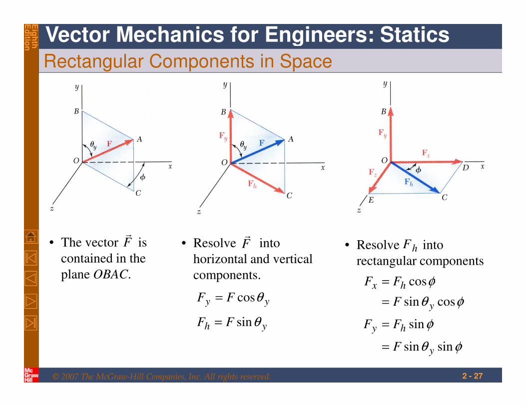
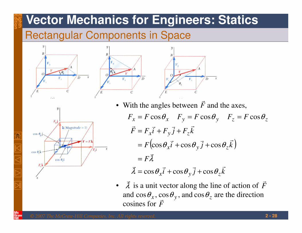
Rectangular Components in Space
• The vector is
contained in the
plane OBAC.
Fr
• Resolve into
horizontal and vertical
components.
yh FF θsin=
Fr
yy FF θcos=
• Resolve into
rectangular componentshF
φθ
φ
φθ
φ
sinsin
sin
cossin
cos
y
hy
y
hx
F
FF
F
FF
=
=
=
=
© 2007 The McGraw-Hill Companies, Inc. All rights reserved.
Vector Mechanics for Engineers: Statics
Eig
hth
Ed
ition
2 - 28
Rectangular Components in Space
• With the angles between and the axes,Fr
( )
kji
F
kjiF
kFjFiFF
FFFFFF
zyx
zyx
zyx
zzyyxx
rrrr
r
rrr
rrrr
θθθλ
λ
θθθ
θθθ
coscoscos
coscoscos
coscoscos
++=
=
++=
++=
===
• is a unit vector along the line of action of
and are the direction
cosines for
Fr
Fr
λr
zyx θθθ cos and,cos,cos
© 2007 The McGraw-Hill Companies, Inc. All rights reserved.
Vector Mechanics for Engineers: Statics
Eig
hth
Ed
ition
2 - 29
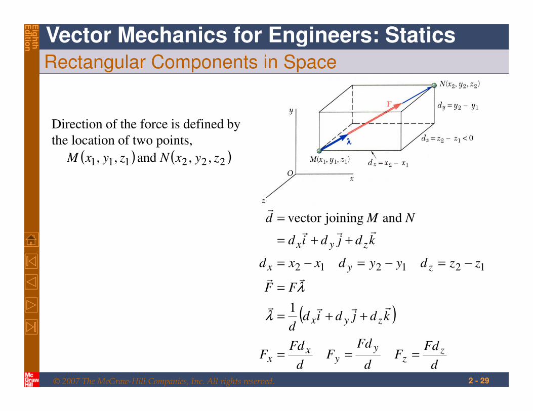
Rectangular Components in Space
Direction of the force is defined by
the location of two points,
( ) ( )222111 ,, and ,, zyxNzyxM
( )
d
FdF
d
FdF
d
FdF
kdjdidd
FF
zzdyydxxd
kdjdid
NMd
zz
yy
xx
zyx
zyx
zyx
===
++=
=
−=−=−=
++=
=
rrrr
rr
rrr
r
1
and joining vector
121212
λ
λ
© 2007 The McGraw-Hill Companies, Inc. All rights reserved.
Vector Mechanics for Engineers: Statics
Eig
hth
Ed
ition
2 - 30
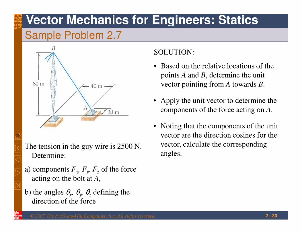
Sample Problem 2.7
The tension in the guy wire is 2500 N.
Determine:
a) components Fx, Fy, Fz of the force
acting on the bolt at A,
b) the angles θx, θy, θz defining the
direction of the force
SOLUTION:
• Based on the relative locations of the
points A and B, determine the unit
vector pointing from A towards B.
• Apply the unit vector to determine the
components of the force acting on A.
• Noting that the components of the unit
vector are the direction cosines for the
vector, calculate the corresponding
angles.
© 2007 The McGraw-Hill Companies, Inc. All rights reserved.
Vector Mechanics for Engineers: Statics
Eig
hth
Ed
ition
2 - 31
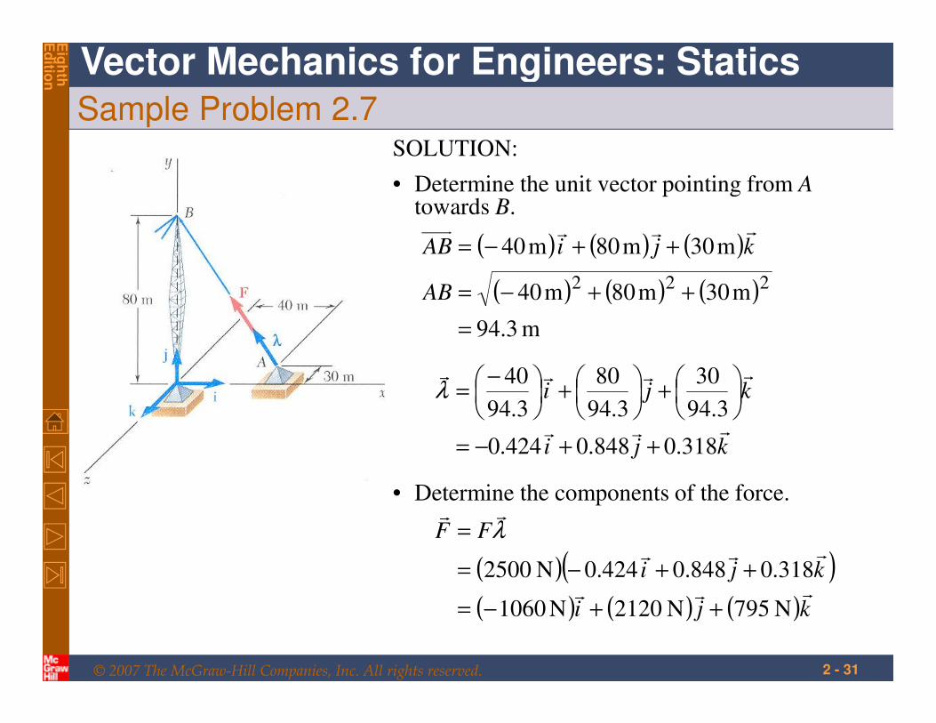
Sample Problem 2.7SOLUTION:
• Determine the unit vector pointing from Atowards B.
( ) ( ) ( )
( ) ( ) ( )
m 3.94
m30m80m40
m30m80m40
222
=
++−=
++−=
AB
kjiABrrr
• Determine the components of the force.
( )( )( ) ( ) ( )kji
kji
FF
rrr
rrr
rr
N 795N 2120N1060
318.0848.0424.0N 2500
++−=
++−=
= λ
kji
kji
rrr
rrrr
318.0848.0424.0
3.94
30
3.94
80
3.94
40
++−=
+
+
−=λ
© 2007 The McGraw-Hill Companies, Inc. All rights reserved.
Vector Mechanics for Engineers: Statics
Eig
hth
Ed
ition
2 - 32
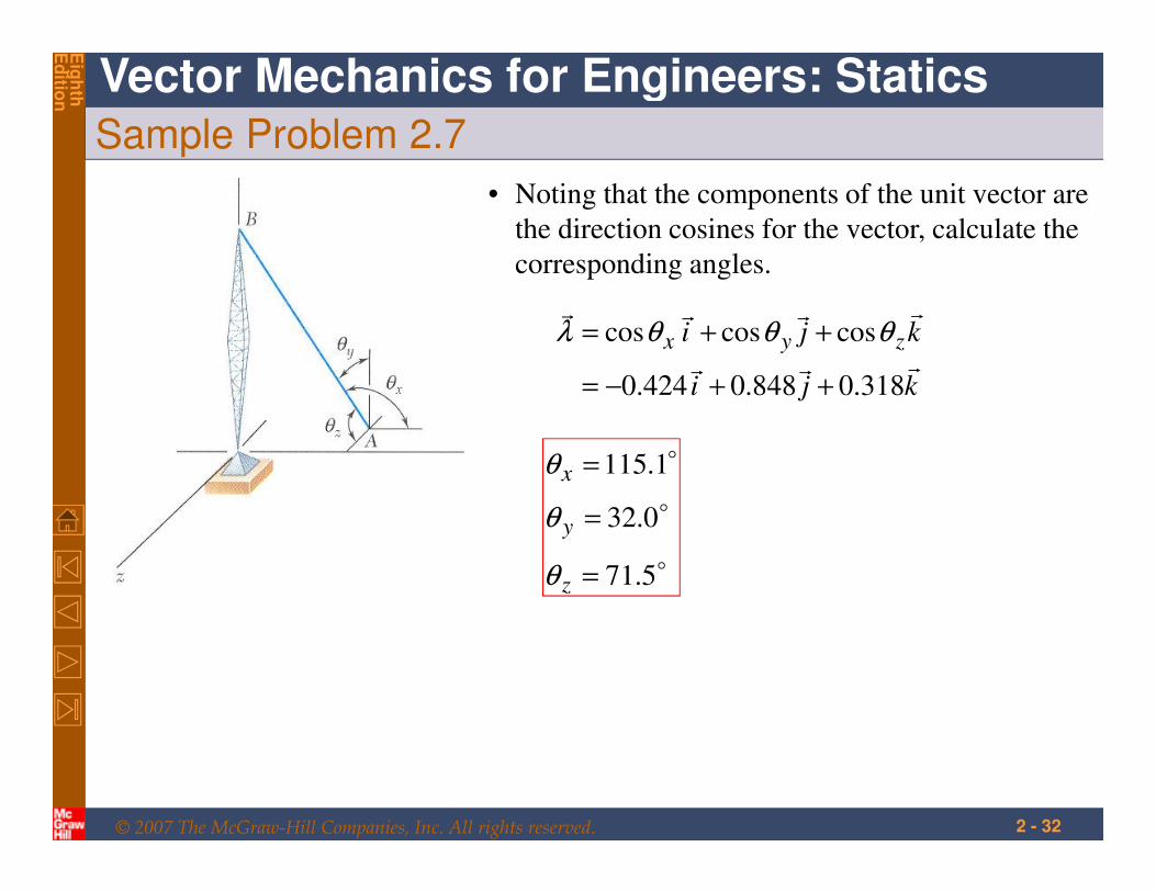
Sample Problem 2.7
• Noting that the components of the unit vector are
the direction cosines for the vector, calculate the
corresponding angles.
kji
kji zyxrrr
rrrr
318.0848.0424.0
coscoscos
++−=
++= θθθλ
o
o
o
5.71
0.32
1.115
=
=
=
z
y
x
θ
θ
θ