vb6, vb7 3-pole mini reversing contactors – with screw ...vb6, vb7 3-pole mini reversing...
TRANSCRIPT
2CD
C10
201
6C
02
01
3/4 | ABB
VB6, VB7 3-pole mini reversing contactors – with screw terminals4 to 5.5 kWAC operated
DescriptionVB6, VB7 3-pole compact design reversing contactors are space optimized control products mainly used for switching resistive or motor loads up to 690 V AC.These reversing contactors are designed with: – built-in mechanical interlock. The coils must be mutually interlocked electrically and coils must be de-energised for 50 ms at least to prevent phase to phase short circuit on the arc.
– control circuit: AC operated – low coil consumption (3.5 VA at pull-in and at holding).
– hum-free coil – add-on auxiliary contact blocks for front mounting – designed for rail or wall mounting.
Ordering detailsIEC UL/CSA Rated control circuit
voltage UC
Auxiliarycontactsfitted
Type Order code Pkg qty
Weight(1 pce)Rated operational 3-phase
motor rating 480 V
General use rating
power
400 V AC-3
current θ ≤ 40 °C
AC-1 50 Hz 60 Hz
kW A hp V AC V AC kg
VB6 mini reversing contactors
4 20 3 300 V / 12 A
24 24 1 0 VB6-30-10-01 GJL1211901R0101 5 0.3550 1 VB6-30-01-01 GJL1211901R0011 5 0.355
42 42 1 0 VB6-30-10-02 GJL1211901R0102 5 0.3550 1 VB6-30-01-02 GJL1211901R0012 5 0.355
48 48 1 0 VB6-30-10-03 GJL1211901R0103 5 0.3550 1 VB6-30-01-03 GJL1211901R0013 5 0.355
110 … 127 110 … 127 1 0 VB6-30-10-84 GJL1211901R8104 5 0.3550 1 VB6-30-01-84 GJL1211901R8014 5 0.355
220 … 240 220 … 240 1 0 VB6-30-10-80 GJL1211901R8100 5 0.3550 1 VB6-30-01-80 GJL1211901R8010 5 0.355
380 … 415 380 … 415 1 0 VB6-30-10-85 GJL1211901R8105 5 0.3550 1 VB6-30-01-85 GJL1211901R8015 5 0.355
VB7 mini reversing contactors
5.5 20 5 600 V / 16 A
24 24 1 0 VB7-30-10-01 GJL1311901R0101 5 0.3550 1 VB7-30-01-01 GJL1311901R0011 5 0.355
42 42 1 0 VB7-30-10-02 GJL1311901R0102 5 0.3550 1 VB7-30-01-02 GJL1311901R0012 5 0.355
48 48 1 0 VB7-30-10-03 GJL1311901R0103 5 0.3550 1 VB7-30-01-03 GJL1311901R0013 5 0.355
110 … 127 110 … 127 1 0 VB7-30-10-84 GJL1311901R8104 5 0.3550 1 VB7-30-01-84 GJL1311901R8014 5 0.355
220 … 240 220 … 240 1 0 VB7-30-10-80 GJL1311901R8100 5 0.3550 1 VB7-30-01-80 GJL1311901R8010 5 0.355
380 … 415 380 … 415 1 0 VB7-30-10-85 GJL1311901R8105 5 0.3550 1 VB7-30-01-85 GJL1311901R8015 5 0.355
Other types on request.
2C
DC
2110
06F0
011
VB7-30-10
Main dimensions mm, inches
4.5 0.18"
43.7 1.72"
46.7 1.84"
96.2 3.79"
42.2
1.
66"
45.2
1.
78"
57.5
2.
26"
2CD
C21
2005
F001
1
VB6, VB7
3
2CD
C10
20
43
C0
201
ABB | 3/39
B6, B7, BC6, BC7, TBC7 3- and 4-pole mini contactorsVB6, VB7, VBC6, VBC7 3- and 4-pole mini reversing contactorsTechnical data
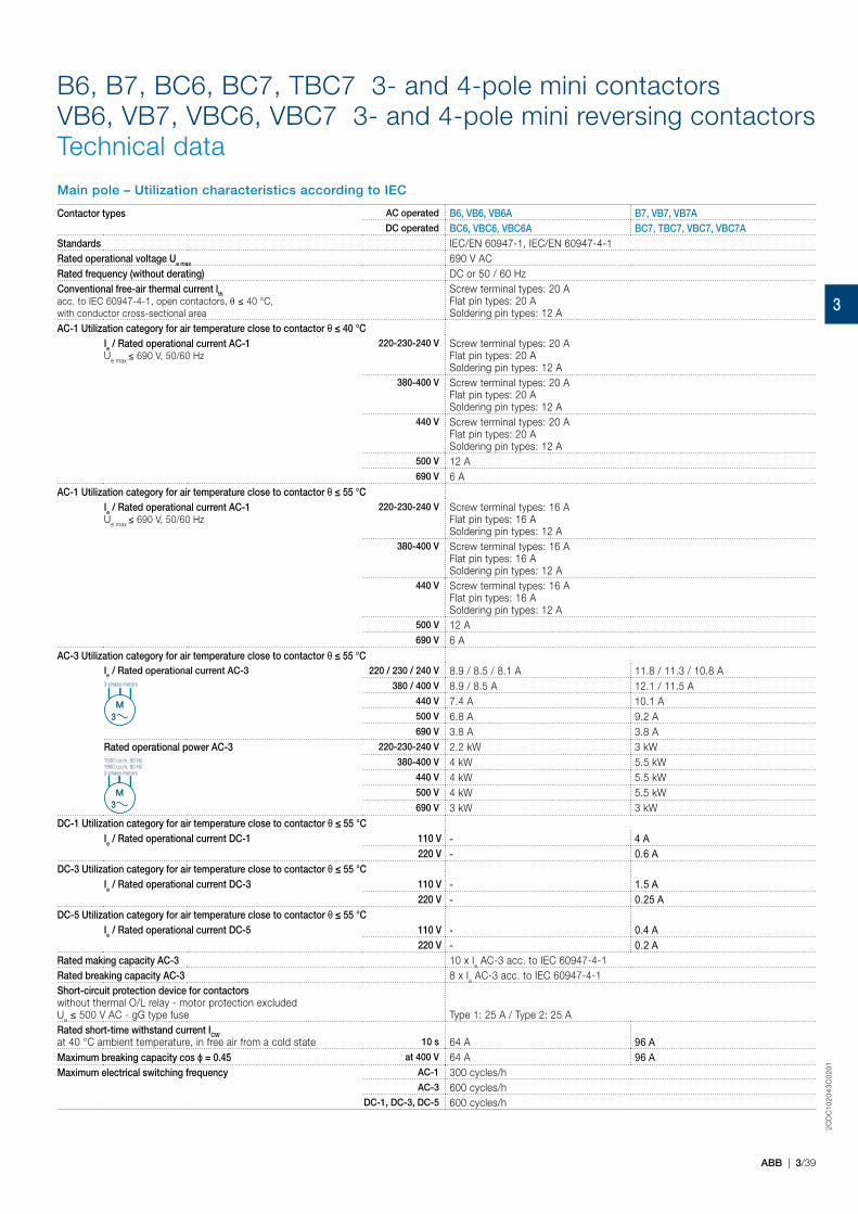
Main pole – Utilization characteristics according to IEC
Contactor types AC operated B6, VB6, VB6A B7, VB7, VB7ADC operated BC6, VBC6, VBC6A BC7, TBC7, VBC7, VBC7A
Standards IEC/EN 60947-1, IEC/EN 60947-4-1Rated operational voltage Ue max 690 V ACRated frequency (without derating) DC or 50 / 60 HzConventional free-air thermal current lth acc. to IEC 60947-4-1, open contactors, θ ≤ 40 °C, with conductor cross-sectional area
Screw terminal types: 20 AFlat pin types: 20 ASoldering pin types: 12 A
AC-1 Utilization category for air temperature close to contactor θ ≤ 40 °CIe / Rated operational current AC-1 Ue max ≤ 690 V, 50/60 Hz
220-230-240 V Screw terminal types: 20 AFlat pin types: 20 ASoldering pin types: 12 A
380-400 V Screw terminal types: 20 AFlat pin types: 20 ASoldering pin types: 12 A
440 V Screw terminal types: 20 AFlat pin types: 20 ASoldering pin types: 12 A
500 V 12 A690 V 6 A
AC-1 Utilization category for air temperature close to contactor θ ≤ 55 °CIe / Rated operational current AC-1 Ue max ≤ 690 V, 50/60 Hz
220-230-240 V Screw terminal types: 16 AFlat pin types: 16 ASoldering pin types: 12 A
380-400 V Screw terminal types: 16 AFlat pin types: 16 ASoldering pin types: 12 A
440 V Screw terminal types: 16 AFlat pin types: 16 ASoldering pin types: 12 A
500 V 12 A690 V 6 A
AC-3 Utilization category for air temperature close to contactor θ ≤ 55 °CIe / Rated operational current AC-3 220 / 230 / 240 V 8.9 / 8.5 / 8.1 A 11.8 / 11.3 / 10.8 A3-phase motors 380 / 400 V 8.9 / 8.5 A 12.1 / 11.5 A
440 V 7.4 A 10.1 A500 V 6.8 A 9.2 A690 V 3.8 A 3.8 A
Rated operational power AC-3 220-230-240 V 2.2 kW 3 kW1500 r.p.m. 50 Hz1800 r.p.m. 60 Hz3-phase motors
380-400 V 4 kW 5.5 kW440 V 4 kW 5.5 kW500 V 4 kW 5.5 kW690 V 3 kW 3 kW
DC-1 Utilization category for air temperature close to contactor θ ≤ 55 °CIe / Rated operational current DC-1 110 V - 4 A
220 V - 0.6 ADC-3 Utilization category for air temperature close to contactor θ ≤ 55 °C
Ie / Rated operational current DC-3 110 V - 1.5 A220 V - 0.25 A
DC-5 Utilization category for air temperature close to contactor θ ≤ 55 °CIe / Rated operational current DC-5 110 V - 0.4 A
220 V - 0.2 ARated making capacity AC-3 10 x Ie AC-3 acc. to IEC 60947-4-1Rated breaking capacity AC-3 8 x Ie AC-3 acc. to IEC 60947-4-1Short-circuit protection device for contactorswithout thermal O/L relay - motor protection excluded Ue ≤ 500 V AC - gG type fuse Type 1: 25 A / Type 2: 25 ARated short-time withstand current ICWat 40 °C ambient temperature, in free air from a cold state 10 s 64 A 96 AMaximum breaking capacity cos ϕ = 0.45 at 400 V 64 A 96 AMaximum electrical switching frequency AC-1 300 cycles/h
AC-3 600 cycles/hDC-1, DC-3, DC-5 600 cycles/h
M3M
3
M3M
3
3
2CD
C10
20
43
C0
201
3/40 | ABB
B6, B7, BC6, BC7, TBC7 3- and 4-pole mini contactorsVB6, VB7, VBC6, VBC7 3- and 4-pole mini reversing contactorsTechnical data
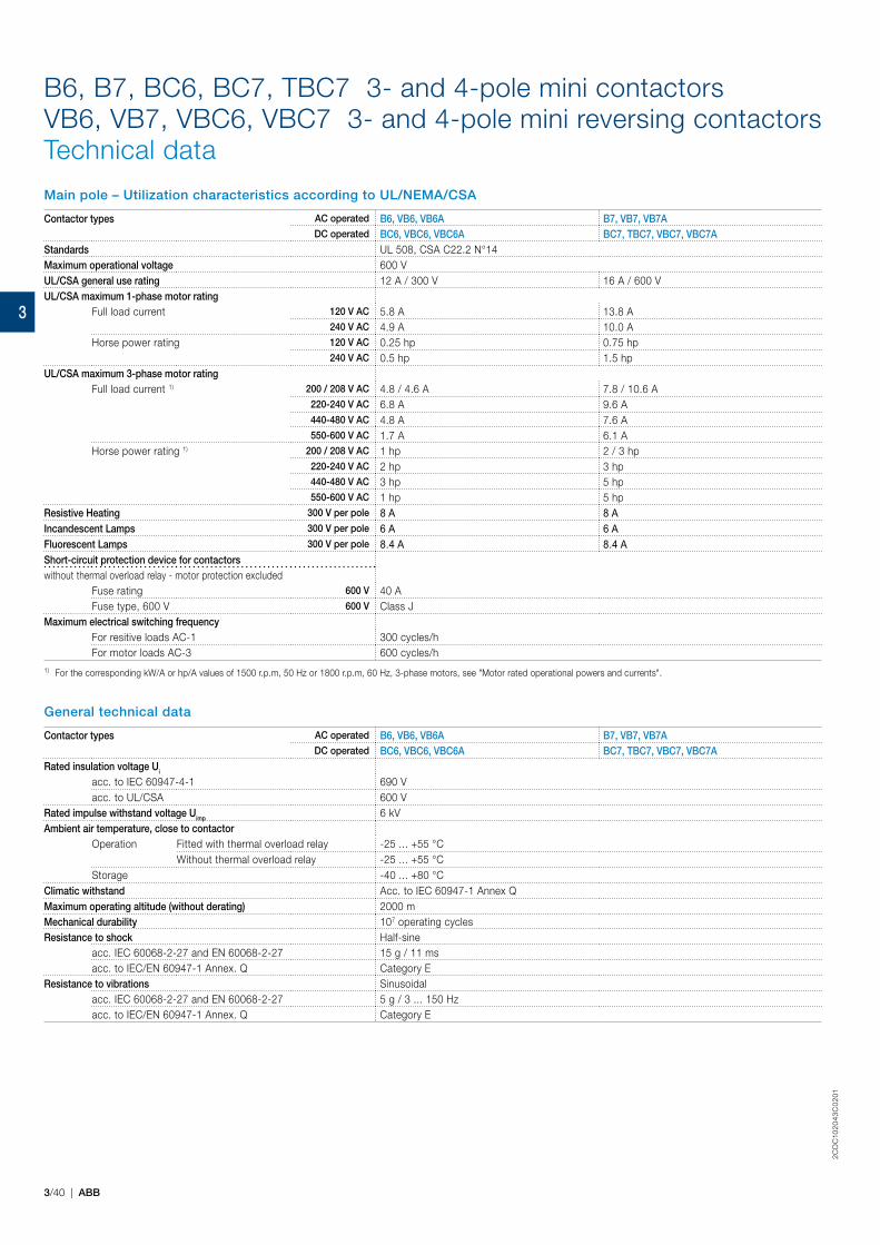
Main pole – Utilization characteristics according to UL/NEMA/CSA
Contactor types AC operated B6, VB6, VB6A B7, VB7, VB7ADC operated BC6, VBC6, VBC6A BC7, TBC7, VBC7, VBC7A
Standards UL 508, CSA C22.2 N°14Maximum operational voltage 600 VUL/CSA general use rating 12 A / 300 V 16 A / 600 VUL/CSA maximum 1-phase motor rating
Full load current 120 V AC 5.8 A 13.8 A240 V AC 4.9 A 10.0 A
Horse power rating 120 V AC 0.25 hp 0.75 hp240 V AC 0.5 hp 1.5 hp
UL/CSA maximum 3-phase motor ratingFull load current 1) 200 / 208 V AC 4.8 / 4.6 A 7.8 / 10.6 A
220-240 V AC 6.8 A 9.6 A440-480 V AC 4.8 A 7.6 A550-600 V AC 1.7 A 6.1 A
Horse power rating 1) 200 / 208 V AC 1 hp 2 / 3 hp220-240 V AC 2 hp 3 hp440-480 V AC 3 hp 5 hp550-600 V AC 1 hp 5 hp
Resistive Heating 300 V per pole 8 A 8 AIncandescent Lamps 300 V per pole 6 A 6 AFluorescent Lamps 300 V per pole 8.4 A 8.4 AShort-circuit protection device for contactorswithout thermal overload relay - motor protection excluded
Fuse rating 600 V 40 AFuse type, 600 V 600 V Class J
Maximum electrical switching frequencyFor resitive loads AC-1 300 cycles/hFor motor loads AC-3 600 cycles/h
1) For the corresponding kW/A or hp/A values of 1500 r.p.m, 50 Hz or 1800 r.p.m, 60 Hz, 3-phase motors, see "Motor rated operational powers and currents".
General technical data
Contactor types AC operated B6, VB6, VB6A B7, VB7, VB7ADC operated BC6, VBC6, VBC6A BC7, TBC7, VBC7, VBC7A
Rated insulation voltage Ui
acc. to IEC 60947-4-1 690 Vacc. to UL/CSA 600 V
Rated impulse withstand voltage Uimp 6 kVAmbient air temperature, close to contactor
Operation Fitted with thermal overload relay -25 ... +55 °CWithout thermal overload relay -25 ... +55 °C
Storage -40 ... +80 °CClimatic withstand Acc. to IEC 60947-1 Annex QMaximum operating altitude (without derating) 2000 mMechanical durability 107 operating cyclesResistance to shock Half-sine
acc. IEC 60068-2-27 and EN 60068-2-27 15 g / 11 msacc. to IEC/EN 60947-1 Annex. Q Category E
Resistance to vibrations Sinusoidalacc. IEC 60068-2-27 and EN 60068-2-27 5 g / 3 ... 150 Hzacc. to IEC/EN 60947-1 Annex. Q Category E
3
2CD
C10
20
43
C0
201
ABB | 3/41
B6, B7, BC6, BC7, TBC7 3- and 4-pole mini contactorsVB6, VB7, VBC6, VBC7 3- and 4-pole mini reversing contactorsTechnical data
Magnet system characteristics for B6, B7 contactors
Contactor types AC operated B6, VB6 B7, VB7Coil operating limits acc. to IEC 60947-4-1 AC supply 0.85 ... 1.1 x Uc
AC control voltageRated control circuit voltage UC See ordering tablesCoil consumption Average pull-in value 3.5 VA / 3.5 W
Average holding value 3.5 VA / 3.5 WDrop-out voltage 0.20 ... 0.75 % of Uc
Magnet system characteristics for BC6, BC7 contactors
Contactor types DC operated BC6, VBC6 BC7, VBC7Coil operating limits acc. to IEC 60947-4-1 DC supply 0.85 ... 1.1 x Uc
AC control voltageRated control circuit voltage UC See ordering tablesCoil consumption 1) Average pull-in value 3.5 VA / 3.5 W
Average holding value 3.5 VA / 3.5 WDrop-out voltage in % of UC min 0.10 ... 0.75 x UC
1) Interface mini-contactors: see coil consumption on ordering details pages
Magnet system characteristics for TBC7 contactors
Contactor types DC operated TBC7Coil operating limits acc. to IEC 60947-4-1 DC supply Wide range voltage supply see ordering tables, UCmin ... UCmax
AC control voltageRated control circuit voltage UC See ordering tablesCoil consumption Average pull-in value 5 VA / 5 W
Average holding value 5 VA / 5 WDrop-out voltage in % of UC min ≤ 0.20 % of UCmin
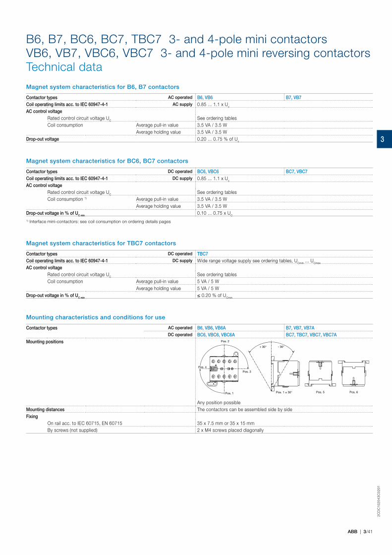
Mounting characteristics and conditions for use
Contactor types AC operated B6, VB6, VB6A B7, VB7, VB7ADC operated BC6, VBC6, VBC6A BC7, TBC7, VBC7, VBC7A
Mounting positions
Pos. 1
Pos. 2
Pos. 4
Pos. 1 ± 30°
- 30°+ 30°
Pos. 5 Pos. 6
Pos. 3
Any position possibleMounting distances The contactors can be assembled side by sideFixing
On rail acc. to IEC 60715, EN 60715 35 x 7.5 mm or 35 x 15 mmBy screws (not supplied) 2 x M4 screws placed diagonally
3
2CD
C10
20
43
C0
201
3/42 | ABB
B6, B7, BC6, BC7, TBC7 3- and 4-pole mini contactorsVB6, VB7, VBC6, VBC7 3- and 4-pole mini reversing contactorsTechnical data
Built-in auxiliary contacts according to IEC
Contactor types AC operated B6, VB6, VB6A B7, VB7, VB7ADC operated BC6, VBC6, VBC6A BC7, TBC7, VBC7, VBC7A
Standards IEC/EN 60947-1, IEC/EN 60947-4-1Rated operational voltage Ue max 690 VRated frequency (without derating) DC or 50 / 60 HzConventional free-air thermal current lth θ ≤ 40 °C 6 AIe / Rated operational current AC-15acc. to IEC 60947-5-1
24 V 50/60 Hz 4 A110-120 V 50/60 Hz 4 A
220-230-240 V 50/60 Hz 4 A380-400 V 50/60 Hz 3 A
440 V 50/60 Hz 3 AIe / Rated operational current DC-13acc. to IEC 60947-5-1
24 V DC 2.5 A110 V DC 0.7 A
220 - 240 V DC 0.4 AShort-circuit protection device 6 A, Type gGMinimum switching capacity with failure rate acc. to IEC 60947-5-4 17 V / 5 mAMaximum electrical switching frequency AC-15 600 cycles/h
DC-13 600 cycles/h
Built-in auxiliary contacts according to UL/CSA
Contactor types AC operated B6, VB6, VB6A B7, VB7, VB7ADC operated BC6, VBC6, VBC6A BC7, TBC7, VBC7, VBC7A
Max. operational voltage 600 V ACPilot duty A600
AC thermal rated current 5 A
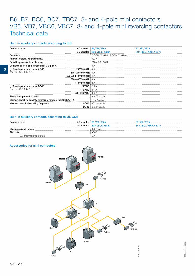
Accessories for mini contactors
CA6
B6
B7
RV-BC6
RV-BC6
RV-BC6
RV-BC6
E16DU
T16
CAF6
BEA7MS116
MS132MO132
2CD
C21
2018
F001
1
3
2CD
C10
20
43
C0
201
ABB | 3/43
B6, B7, BC6, BC7, TBC7 3- and 4-pole mini contactorsVB6, VB7, VBC6, VBC7 3- and 4-pole mini reversing contactorsTechnical data
Connection characteristics
Contactor types AC operated B6, VB6, VB6A B7, VB7, VB7ADC operated BC6, VBC6, VBC6A BC7, TBC7, VBC7, VBC7A
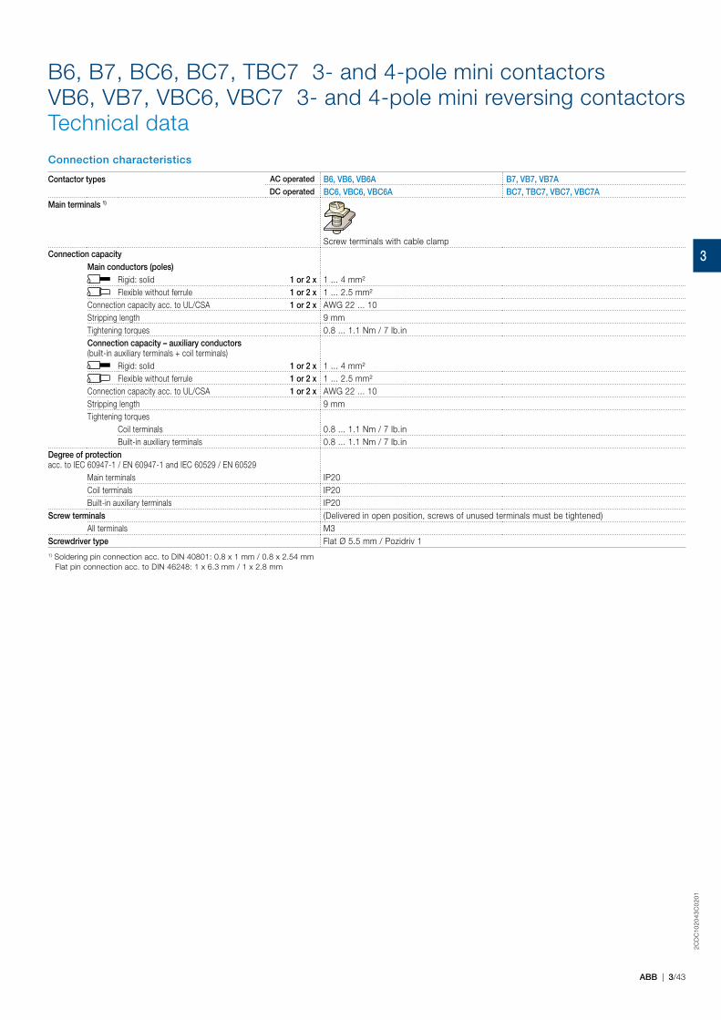
Main terminals 1)
Screw terminals with cable clampConnection capacity
Main conductors (poles)Rigid: solid 1 or 2 x 1 ... 4 mm²Flexible without ferrule 1 or 2 x 1 ... 2.5 mm²
Connection capacity acc. to UL/CSA 1 or 2 x AWG 22 ... 10Stripping length 9 mmTightening torques 0.8 ... 1.1 Nm / 7 lb.inConnection capacity – auxiliary conductors(built-in auxiliary terminals + coil terminals)
Rigid: solid 1 or 2 x 1 ... 4 mm²Flexible without ferrule 1 or 2 x 1 ... 2.5 mm²
Connection capacity acc. to UL/CSA 1 or 2 x AWG 22 ... 10Stripping length 9 mmTightening torques
Coil terminals 0.8 ... 1.1 Nm / 7 lb.inBuilt-in auxiliary terminals 0.8 ... 1.1 Nm / 7 lb.in
Degree of protectionacc. to IEC 60947-1 / EN 60947-1 and IEC 60529 / EN 60529
Main terminals IP20Coil terminals IP20Built-in auxiliary terminals IP20
Screw terminals (Delivered in open position, screws of unused terminals must be tightened)All terminals M3
Screwdriver type Flat Ø 5.5 mm / Pozidriv 11) Soldering pin connection acc. to DIN 40801: 0.8 x 1 mm / 0.8 x 2.54 mm Flat pin connection acc. to DIN 46248: 1 x 6.3 mm / 1 x 2.8 mm
3