vaunix technology corporation - woken · 3 vaunix technology corporation lab brick digital...
TRANSCRIPT

Vaunix Technology CorporationLab Brick® Family of Digital Attenuators
Operation Manualand
Programming Guide
Revision A

Vaunix Technology Corporation
2
Lab Brick Digital Attenuator
CertificationVaunix Technology Corporation certifies that this product met its published speci-fications at the time of shipment from the factory.
WarrantyLab Brick Signal Generators are warranted against defects in material and work-manship for a period of one year from the date of shipment.
LIMITATION OF WARRANTYThe foregoing warranty does not apply to connectors that have failed due tonormal wear. Also, the warranty does not apply to defects resulting from im-proper or inadequate maintenance by the Buyer, unauthorized modification ormisuse, or operation outside of the environmental specifications of the product.No other warranty is expressed or implied, and the remedies provided herein arethe Buyer’s sole and exclusive remedies. Vaunix Technology Corporation shallnot be liable for any direct, indirect, special, incidental, or consequential dam-ages, whether based on contract, tort, or any other legal theory.
NOTICEVaunix has prepared this manual for use by Vaunix Company personnel andcustomers as a guide for the proper installation, operation, and maintenance ofVaunix equipment and computer programs. The drawings, specifications, andinformation contained herein are the property of Vaunix Technology Corporation,and any unauthorized use or disclosure of these drawings, specifications, andinformation is prohibited; they shall not be reproduced, copied, or used in wholeor in part as the basis for manufacture or sale of the equipment or softwareprograms without the prior written consent of Vaunix Technology Corporation.

3
Lab Brick Digital AttenuatorVaunix Technology Corporation
This ISM apparatus meets all requirements of the Canadian Interference-CausingEquipment regulations.
Ce generateur de fequence radio ISM respecte toutes les exigences du Reglementsur le materiel brouilleur du Canada.
Waste Electrical and Electronic Equipment (WEEE) Directive 2002/96/EC
This instruction complies with the WEEE Directive (2002/96/EC) marking require-ment. This affixed product label indicates that you must not discard this electrical/electronic product in domestic household waste.
To return an unwanted instrument, contact Vaunix Technology Corporation.
Vaunix Technology Corporation
4
Lab Brick Digital Attenuator
Table of Contents1.0 GENERAL INFORMATION ...................................................................... 5
1.1 General Safety Information ................................................................................. 52.0 GETTING STARTED .................................................................................. 6
2.1 System Requirements ........................................................................................... 62.2 Installation of the Graphical User Interface (GUI) ........................................... 62.3 Using the Lab Brick Digital Attenuator ............................................................. 62.4 Using Multiple Lab Brick Digital Attenuators .................................................. 7
3.0 OPERATING FEATURES AND CONTROLS ......................................... 83.1 Attenuation ............................................................................................................ 83.1.1 Manual Attenuation.............................................................................................. 83.1.2 Configuring the Manual Attenuation Step Size ................................................. 93.1.3 Configuring the Automated Attenuation Step Function ................................... 9 3.3 Setting the Initial Operating State ...................................................................... 9
4.0 SPECIFICATIONS .................................................................................... 105.0 OPTIONAL ACCESSORIES.................................................................... 116.0 PROGRAMMING GUIDE ....................................................................... 12
6.1 Identifying the Lab Brick Digital Attenuators ................................................. 126.2 Controlling the Lab Brick Digital Attenuators ................................................ 146.2.1 Commands ........................................................................................................... 146.2.2 Responses ............................................................................................................. 176.3 Tips and Suggestions .......................................................................................... 21
7.0 MECHANICAL OUTLINE ...................................................................... 22

5
Lab Brick Digital AttenuatorVaunix Technology Corporation
1.0 GENERAL INFORMATION
This guide contains information on the installation , operation and specifications ofthe Lab Brick® Family of Digital Attenuators.
1.1 General Safety Information
To prevent the risk of personal injury and loss related to equipment malfunction,Vaunix Technology Corporation provides the following safety information. For youown safety please read this section before operating the equipment.
Warning
Before connecting your Lab Brick Digital Attenuator to other instruments ensurethat all instruments are connected to earth ground. Any interruption of the earthgrounding may cause a potential shock hazard.
Caution
• The Lab Brick Digital Attenuator contains components which are sensitive toElectro Static Discharge (ESD). Proper ESD precautions must be maintainedat all times while using this equipment.
• This equipment has no serviceable parts.• To prevent the risk of electrical shock or damage to precision components, do
not remove the equipment covers.• Unauthorized entry into the unit voids all warranties.
Vaunix Technology Corporation
6
Lab Brick Digital Attenuator
2.0 GETTING STARTED
Prior to installing your Lab Brick Digital Attenuator, verify the contents of the pack-age. The package should contain:
Quantity 1 Lab Brick Digital Attenuator
Quantity 1 Cable - USB Type A male/ Mini-B male
Quantity 1 Flash Drive containing the manual and the Graphical User Interfaceprogram
2.1 System Requirements
The Lab Brick Digital Attenuator runs from a standard PC or lap top computer withthe following minimum requirements:
• Operating System - Windows® 2000, Windows® XP or Windows® Vista• RAM - 256 MB• Processor Speed - 512 MHz• A minimum of one USB portNo other AC or DC supply is required as the power for this unit is delivered from aUSB port on the computer or a self powered USB hub.
2.2 Installation of the Graphical User Interface (GUI)
The Lab Brick is controlled through the GUI program supplied on the provided USBflash drive. To install the GUI proceed with the following steps:
• Insert the supplied USB flash drive into an available USB port on the computer• Run the program “Setup.exe”• Follow the instructions on the screen• After Installation is complete, remove the USB flash drive
2.3 Using the Lab Brick Digital Attenuator
Start the Lab Brick program by selecting the Lab Brick Icon or selecting the LabBrick program from the Start Menu on the computer. Attach the supplied USBcable to the Lab Brick Digital Attenuator and the USB port on the computer. Thegreen LED on the Lab Brick will illuminate as communication with the computer isautomatically established. The GUI program will recognize the device and displaythe model number and serial number in the title bar and lower left corners respec-tively. The Lab Brick is now ready for operation.
7
Lab Brick Digital AttenuatorVaunix Technology Corporation
2.4 Using Multiple Lab Brick Digital Attenuators
Users may operate and control multiple Lab Bricks from a single computer. Startthe Lab Brick GUI as described in section 2.3 for each Lab Brick Digital Attenuatorthat you will control from the computer. Connect each Lab Brick either directly tothe USB port or through a self powered USB hub to the USB port of the computer.The green LED on each Lab Brick will illuminate as communication with the com-puter is automatically established. Each GUI application will automatically connectto one Lab Brick. The GUI will display the model number and serial number of theconnected device in the title bar and lower left corners respectively.
Vaunix Technology Corporation
8
Lab Brick Digital Attenuator
3.0 OPERATING FEATURES AND CONTROLS
The general operation of the Lab Brick Digital Attenuator is designed by the Vaunixengineers to be intuitive and easy to use. This section describes the availablefeatures of the Lab Brick Digital Attenuator.
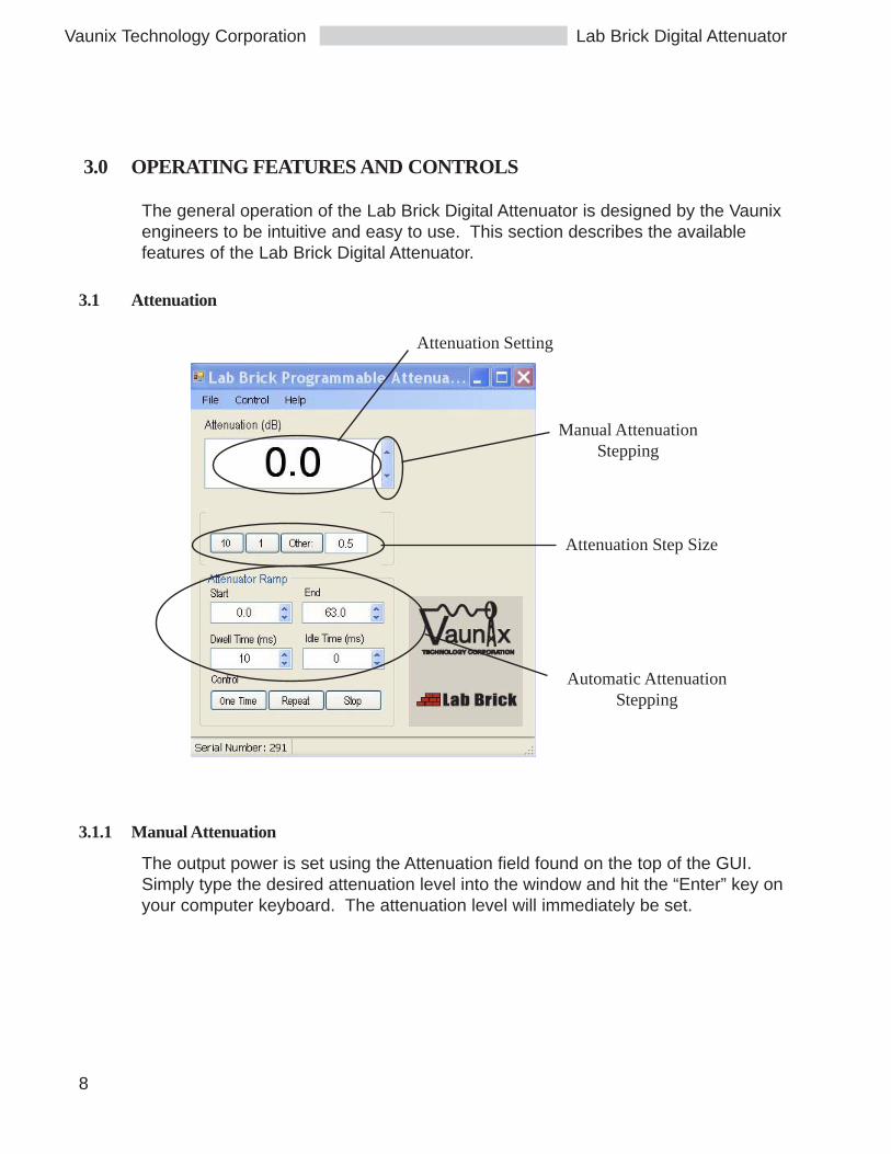
3.1 Attenuation
3.1.1 Manual Attenuation
The output power is set using the Attenuation field found on the top of the GUI.Simply type the desired attenuation level into the window and hit the “Enter” key onyour computer keyboard. The attenuation level will immediately be set.
Attenuation Setting
Manual AttenuationStepping
Attenuation Step Size
Automatic AttenuationStepping

9
Lab Brick Digital AttenuatorVaunix Technology Corporation
3.1.2 Configuring the Manual Attenuation Step Size
The attenuation may also be controlled by using the up and down arrows adjacentto the Power field. Use the controls directly below the Attenuation field to set thedesired step size. Quick select buttons are available for fixed step sizes of 10 dBand 1 dB. Custom step sizes may also be used by selecting “Other” and enteringthe desired step size between 0.5 dB and 63 dB in 0.5 dB increments.
3.1.3 Configuring the Automated Attenuation Step Function
The Lab Brick can be configured to automatically step through a range of attenua-tion. The user must specify the starting attenuation level, final attenuation level,step size, dwell time and time between repeating sweeps. The starting and endingattenuation levels can be configured between 0 dB of attenuation and 63 dB ofattenuation. The dwell time may be configured from 10 milliseconds to 20000milliseconds per step. The step size is configured as described in section 3.1.2.The attenuation level may increase of decrease during the sweep depending if thestarting attenuation is higher or lower than the ending attenuation setting.
By selecting the “One Time” control button, the Lab Brick attenuatorwill sweep fromthe start to the end attenuation level. Upon completing the sweep, the Lab Brickoutput will stay at the end attenuation setting. The user may stop the sweep at anytime by selecting the “Stop” button.
By selecting the “Repeat” control button, the Lab Brick will repeatedly sweep fromthe start to the end attenuation level. The user may stop the sweep at any time byselecting the “Stop” button.
3.3 Setting the Initial Operating State
After configuring the attenuation parameters, the user may select to save thecurrent settings. From the File menu select Save Current Settings.
These settings will be stored within the Lab Brick device. The Lab Brick will nowpower on in this predefined state when plugged into a USB port on any computeror USB self powered hub. The user may change the saved state at any time byrepeating the process.
Vaunix Technology Corporation
10
Lab Brick Digital Attenuator
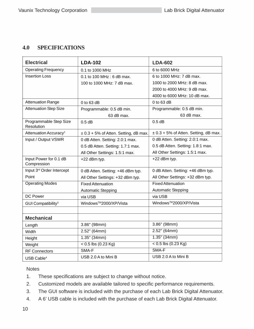
LDA-6026 to 6000 MHz
6 to 1000 MHz: 7 dB max.
1000 to 2000 MHz: 8 dB max.
2000 to 4000 MHz: 9 dB max.
4000 to 6000 MHz: 10 dB max.
0 to 63 dB
Programmable: 0.5 dB min.
63 dB max.
0.5 dB
± 0.3 + 5% of Atten. Setting, dB max.
0 dB Atten. Setting: 2.0:1 max.
0.5 dB Atten. Setting: 1.8:1 max.
All Other Settings: 1.5:1 max.
+22 dBm typ.
0 dB Atten. Setting: +46 dBm typ.
All Other Settings: +32 dBm typ.
Fixed Attenuation
Automatic Stepping
via USB
WindowsTM2000/XP/Vista
3.86" (98mm)
2.52" (64mm)
1.35" (34mm)
< 0.5 lbs (0.23 Kg)
SMA-F
USB 2.0 A to Mini B
4.0 SPECIFICATIONS
LDA-102
0.1 to 1000 MHz
0.1 to 100 MHz : 6 dB max.
100 to 1000 MHz: 7 dB max.
0 to 63 dB
Programmable: 0.5 dB min.
63 dB max.
0.5 dB
± 0.3 + 5% of Atten. Setting, dB max.
0 dB Atten. Setting: 2.0:1 max.
0.5 dB Atten. Setting: 1.7:1 max.
All Other Settings: 1.5:1 max.
+22 dBm typ.
0 dB Atten. Setting: +46 dBm typ.
All Other Settings: +32 dBm typ.
Fixed Attenuation
Automatic Stepping
via USB
WindowsTM2000/XP/Vista
3.86" (98mm)
2.52" (64mm)
1.35" (34mm)
< 0.5 lbs (0.23 Kg)
SMA-F
USB 2.0 A to Mini B
ElectricalOperating Frequency
Insertion Loss
Attenuation Range
Attenuation Step Size
Programmable Step SizeResolution
Attenuation Accuracy2
Input / Output VSWR
Input Power for 0.1 dBCompression
Input 3rd Order Intercept
Point
Operating Modes
DC Power
GUI Compatibility3
MechanicalLength
Width
Height
Weight
RF Connectors
USB Cable4
Notes
1. These specifications are subject to change without notice.
2. Customized models are available tailored to specific performance requirements.
3. The GUI software is included with the purchase of each Lab Brick Digital Attenuator.
4. A 6’ USB cable is included with the purchase of each Lab Brick Digital Attenuator.
11
Lab Brick Digital AttenuatorVaunix Technology Corporation
5.0 OPTIONAL ACCESSORIES
Vaunix offers the following optional accessories for the Lab Brick Digital Attenuatorfamily. Please consult your sales representative or visit LabBrick.com for up todate pricing and availability.
4 Port USB Hub with external power adapter
USB Hub with LAN interface
USB cable TypeA male/Mini-B male - 3 feet
USB cable TypeA male/Mini-B male - 6 feet
USB cable TypeA male/Mini-B male - 9 feet
USB cable TypeA male/Mini-B male - 15 feet

Vaunix Technology Corporation
12
Lab Brick Digital Attenuator
6.0 PROGRAMMING GUIDE
The Lab Brick Digital Attenuators are designed to be easily controlled from eithertheir included control software or from applications programs that directly accessthe digital attenuators. The Lab Bricks use the USB HID class so that applicationssoftware can send commands and receive responses and status messages withoutthe need to install any drivers or other special software components.
As with any USB HID device, there are two phases to working with the Lab Bricks.The first phase is the process of identifying the device you want to work with, andthen opening the device to send and receive commands and status messages fromit. The second phase is communicating with the device, using its commands tocontrol it and reading its responses and status messages to determine the state ofthe Lab Brick.
This documentation includes examples from the Microsoft Windows™ environ-ment. Similar strategies are used to communicate with USB HID devices underother operating systems, and this documentation will provide you with a generalunderstanding of how to control the Lab Bricks under any operating system whichsupports USB HID class devices.
6.1 Identifying the Lab Brick Digital Attenuators
The Lab Brick Digital Attenuators are identified by their Vendor ID (“VID”) andProduct ID (“PID”). Each Lab Brick also has a unique serial number, so that indi-vidual digital attenuators can be identified and selected in situations where mul-tiple, otherwise identical Lab Bricks are connected to one computer.
Normally, in the Microsoft Windows environment, USB devices are identified byrepeatedly calling the SetupDiEnumDeviceInterfaces function and then getting thesymbolic link name for the HID device’s interface with theSetupDiGetDeviceInterfaceDetail function. There are a number of publications thatexplain this technique, Writing Windows WDM Device Drivers by Chris Cant is agood starting point. Also, the Wiimote library by Brian Peek, (http://
13
Lab Brick Digital AttenuatorVaunix Technology Corporation
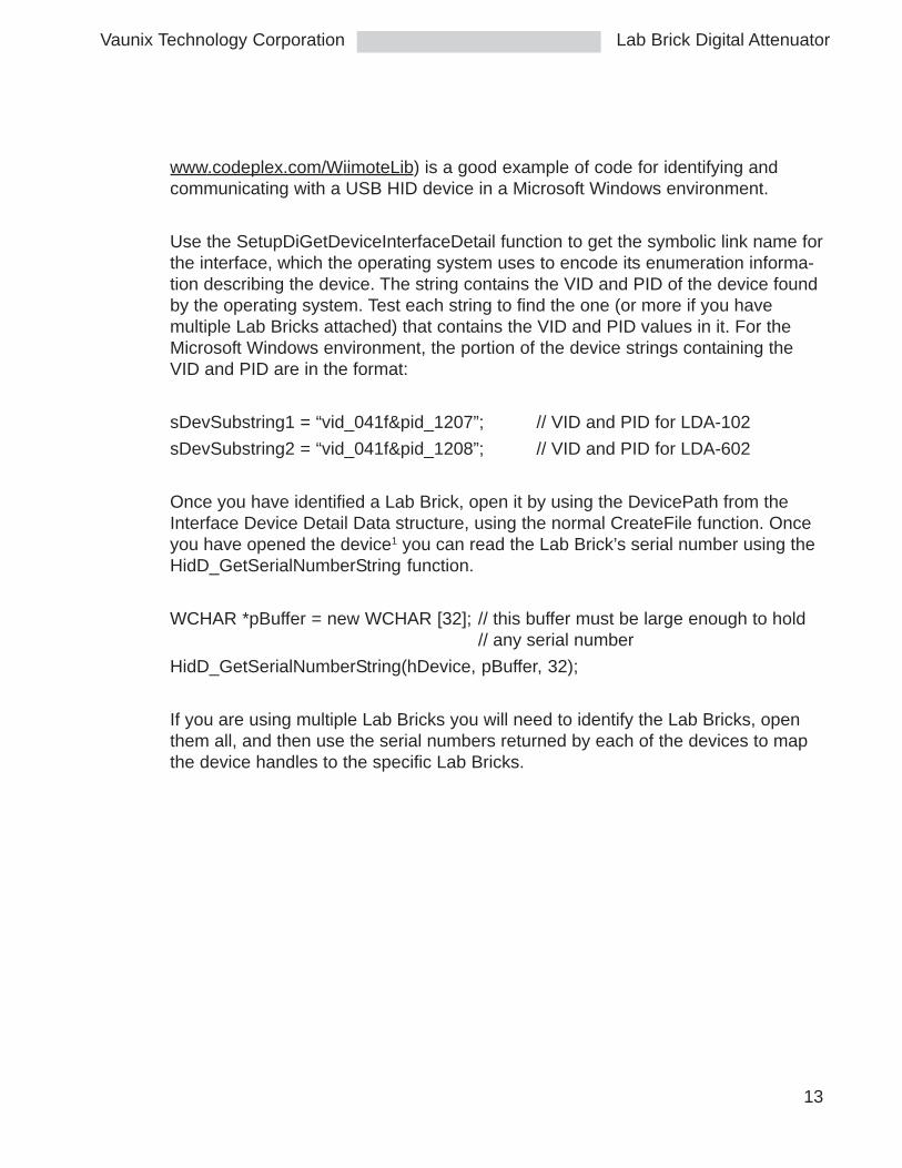
www.codeplex.com/WiimoteLib) is a good example of code for identifying andcommunicating with a USB HID device in a Microsoft Windows environment.
Use the SetupDiGetDeviceInterfaceDetail function to get the symbolic link name forthe interface, which the operating system uses to encode its enumeration informa-tion describing the device. The string contains the VID and PID of the device foundby the operating system. Test each string to find the one (or more if you havemultiple Lab Bricks attached) that contains the VID and PID values in it. For theMicrosoft Windows environment, the portion of the device strings containing theVID and PID are in the format:
sDevSubstring1 = “vid_041f&pid_1207”; // VID and PID for LDA-102
sDevSubstring2 = “vid_041f&pid_1208”; // VID and PID for LDA-602
Once you have identified a Lab Brick, open it by using the DevicePath from theInterface Device Detail Data structure, using the normal CreateFile function. Onceyou have opened the device1 you can read the Lab Brick’s serial number using theHidD_GetSerialNumberString function.
WCHAR *pBuffer = new WCHAR [32]; // this buffer must be large enough to hold// any serial number
HidD_GetSerialNumberString(hDevice, pBuffer, 32);
If you are using multiple Lab Bricks you will need to identify the Lab Bricks, openthem all, and then use the serial numbers returned by each of the devices to mapthe device handles to the specific Lab Bricks.
Vaunix Technology Corporation
14
Lab Brick Digital Attenuator
6.2 Controlling the Lab Brick Digital Attenuators
6.2.1 Commands
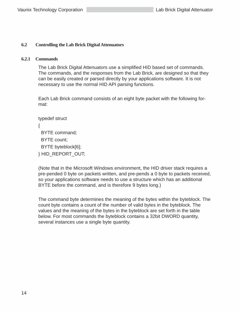
The Lab Brick Digital Attenuators use a simplified HID based set of commands.The commands, and the responses from the Lab Brick, are designed so that theycan be easily created or parsed directly by your applications software. It is notnecessary to use the normal HID API parsing functions.
Each Lab Brick command consists of an eight byte packet with the following for-mat:
typedef struct
{
BYTE command;
BYTE count;
BYTE byteblock[6];
} HID_REPORT_OUT;
(Note that in the Microsoft Windows environment, the HID driver stack requires apre-pended 0 byte on packets written, and pre-pends a 0 byte to packets received,so your applications software needs to use a structure which has an additionalBYTE before the command, and is therefore 9 bytes long.)
The command byte determines the meaning of the bytes within the byteblock. Thecount byte contains a count of the number of valid bytes in the byteblock. Thevalues and the meaning of the bytes in the byteblock are set forth in the tablebelow. For most commands the byteblock contains a 32bit DWORD quantity,several instances use a single byte quantity.
15
Lab Brick Digital AttenuatorVaunix Technology Corporation
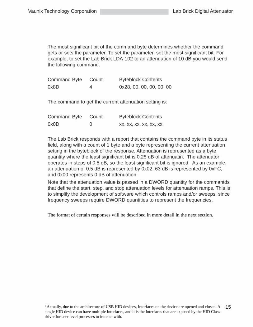
The most significant bit of the command byte determines whether the commandgets or sets the parameter. To set the parameter, set the most significant bit. Forexample, to set the Lab Brick LDA-102 to an attenuation of 10 dB you would sendthe following command:
Command Byte Count Byteblock Contents
0x8D 4 0x28, 00, 00, 00, 00, 00
The command to get the current attenuation setting is:
Command Byte Count Byteblock Contents
0x0D 0 xx, xx, xx, xx, xx, xx
The Lab Brick responds with a report that contains the command byte in its statusfield, along with a count of 1 byte and a byte representing the current attenuationsetting in the byteblock of the response. Attenuation is represented as a bytequantity where the least significant bit is 0.25 dB of attenuatin. The attenuatoroperates in steps of 0.5 dB, so the least significant bit is ignored. As an example,an attenuation of 0.5 dB is represented by 0x02, 63 dB is represented by 0xFC,and 0x00 represents 0 dB of attenuation.
Note that the attenuation value is passed in a DWORD quantity for the commantdsthat define the start, step, and stop attenuation levels for attenuation ramps. This isto simplify the development of software which controls ramps and/or sweeps, sincefrequency sweeps require DWORD quantities to represent the frequencies.
The format of certain responses will be described in more detail in the next section.
1 Actually, due to the architecture of USB HID devices, Interfaces on the device are opened and closed. Asingle HID device can have multiple Interfaces, and it is the Interfaces that are exposed by the HID Classdriver for user level processes to interact with.
Vaunix Technology Corporation
16
Lab Brick Digital Attenuator
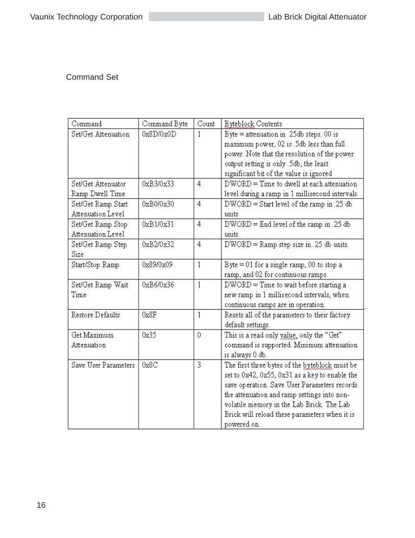
Command Set
17
Lab Brick Digital AttenuatorVaunix Technology Corporation
As an example, this C code function sets the starting attenuation level of a ramp to32 dB
static long AtnStart = 4 * 32; // the attenuation ramp starts at 32 db
void SetRampStart(HANDLE hDevice)
{
unsigned char *ptr = (unsigned char *) &AtnStart;
if (SendReport(hDevice, VNX_ASTART | VNX_SET, ptr, 4)){
printf(“ sending the ramp start attenuation value\n”);
}
}
SetRampStart(hDevice);
Applications programs should ensure that commands are sent with a minimumdelay of 30ms between commands, in order that the Lab Brick can generate andsend its responses.
6.2.2 Responses
The Lab Brick Digital Attenuators send status reports to the host computer periodi-cally while they are operating, and in response to some commands. Applicationsprograms should normally set up and maintain a read thread to capture responsesand status reports from the device. The status reports are designed to be easilyparsed directly by the applications program.
Each Lab Brick response consists of an eight byte packet with the following format:
typedef struct
{
BYTE status;
BYTE count;
BYTE byteblock[6];
} HID_REPORT1;
Vaunix Technology Corporation
18
Lab Brick Digital Attenuator
The status byte contains a value indicating the type of status report, like the com-mands the contents of the byteblock varies depending on the value in the statusbyte. For command responses, the value of the status byte is equal to the com-mand. So for example, the response to the Get Attenuation command shownabove would have a status byte of 0x04, a count of 1 corresponding to the 1 byteused by the attenuation value in the byteblock, and a value of 0x37DC, or .5 db.
Status Byte Count Byteblock
0x04 1 0x02, 00, 00, 00, 00, 00
The Lab Bricks report their status periodically, at an interval equal to the dwell timeset for attenuation ramps, whether or not a ramp is active. During a ramp, thestatus report occurs when the attenuation level changes2. This allows an applica-tions program to track the attenuation level of the Lab Brick during the ramp. Thisallows an applications program to track the attenuation level of the Lab Brick duringthe ramp. The format for the periodic status report is:
typedef struct
{
BYTE pkt_status; // = 0x0E
BYTE count; // = 6
DWORD frequency;
BYTE dev_status;
signed char power;
} VNX_STATUS_REPORT;
Status Byte Count Byteblock
0x0E 6 reserved, dev_status, power
The dev_status byte contains a set of flags which describe the current state of the

19
Lab Brick Digital AttenuatorVaunix Technology Corporation
Lab Brick:
#define STATUS_PLL_LOCK 0x80 // MASK: PLL lock status bit, unused by
#define STATUS_NEW_PARAM 0x40 // MASK: A parameter was set since the last// “Save Settings” command
#define STATUS_OK 0x20 // MASK: A command completed
#define STATUS_ON 0x08 // MASK: The RF HW is on
// Bit masks and equates for the Ramp command byte (stored in Ramp_mode, andreported also in Status)
#define SWP_DIRECTION 0x04 // MASK: bit = 0 for sweep up, 1 forsweep down
#define SWP_CONTINUOUS 0x02 // MASK: bit = 1 for continuoussweeping
#define SWP_ONCE 0x01 // MASK: bit = 1 for single sweep
Power is the current value of the attenuation level as set by the Power Level com-mand.
Since Lab Brick status reports occur asynchronously with respect to commandresponses, the applications code handling reports from the Lab Brick should beable to accept either a command response report or a status report.

Vaunix Technology Corporation
20
Lab Brick Digital Attenuator
Command Response Report Formats
2 The timing of the status reports will vary somewhat depending on the timing of the USB bus transactions, andsoftware processes within the operating system, particularly for dwell times less than 100 milliseconds.
21
Lab Brick Digital AttenuatorVaunix Technology Corporation
6.3 Tips and Suggestions
Remember to handle the error cases for device removal, and close the devicehandles when you are done interacting with the device.
Remember that in the Microsoft Windows environment, the operating system padsthe reports with a byte at the beginning of the report. Make sure to adjust yourstructures accordingly.
If you are programming in C or C++ you can create a set of unions to allow forconvenient access to and conversion of the fields of the reports. For other lan-guages, ensure that the byte order of a 32 bit unsigned integer is the same as thebyte order used in the reports, which has the least significant byte stored in thelowest address.
Vaunix Technology Corporation
22
Lab Brick Digital Attenuator
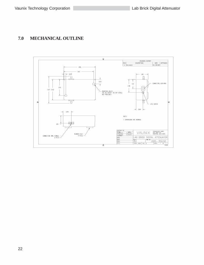
7.0 MECHANICAL OUTLINE

23
Lab Brick Digital AttenuatorVaunix Technology Corporation