variable speed drives - acp&d limited - 'position with ... automation cfw09 variable...
TRANSCRIPT

Variable Speed Drives
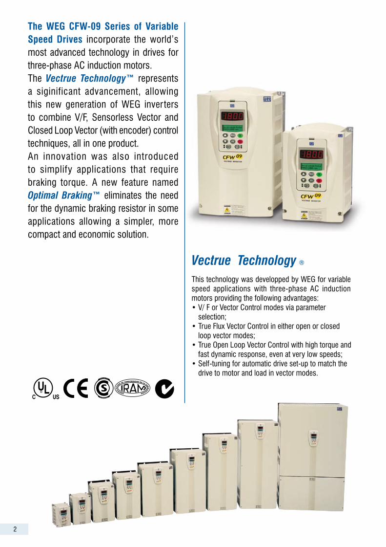
Vectrue Technology ®
This technology was developped by WEG for variable speed applications with three-phase AC induction motors providing the following advantages: • V/ F or Vector Control modes via parameter selection;• True Flux Vector Control in either open or closed loop vector modes;• True Open Loop Vector Control with high torque and fast dynamic response, even at very low speeds;• Self-tuning for automatic drive set-up to match the drive to motor and load in vector modes.
The WEG CFW-09 Series of Variable Speed Drives incorporate the world’s most advanced technology in drives for three-phase AC induction motors.The Vectrue Technology™ represents a siginificant advancement, allowing this new generation of WEG inver ters to combine V/F, Sensorless Vector and Closed Loop Vector (with encoder) control techniques, all in one product.An innovation was also introduced to simplify applications that require braking torque. A new feature named Optimal Braking™ eliminates the need for the dynamic braking resistor in some applications allowing a simpler, more compact and economic solution.
2
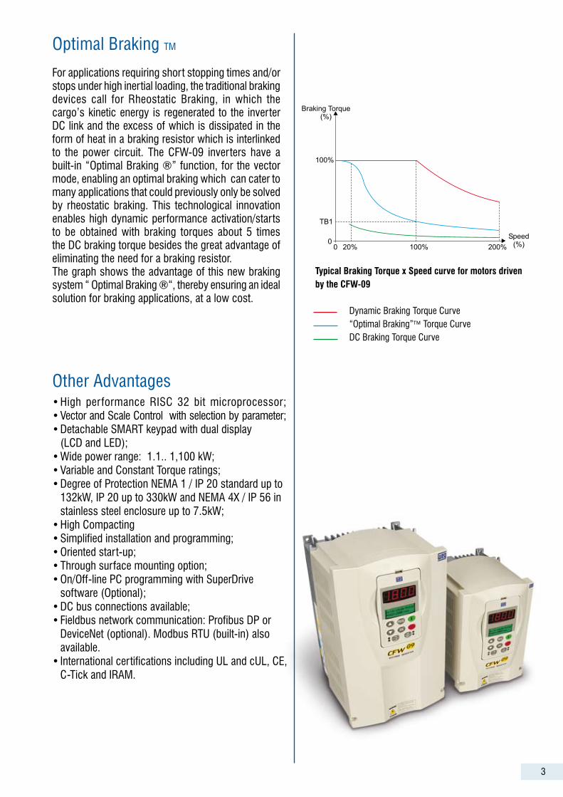
For applications requiring short stopping times and/or stops under high inertial loading, the traditional braking devices call for Rheostatic Braking, in which the cargo’s kinetic energy is regenerated to the inverter DC link and the excess of which is dissipated in the form of heat in a braking resistor which is interlinked to the power circuit. The CFW-09 inverters have a built-in “Optimal Braking ®” function, for the vector mode, enabling an optimal braking which can cater to many applications that could previously only be solved by rheostatic braking. This technological innovation enables high dynamic performance activation/starts to be obtained with braking torques about 5 times the DC braking torque besides the great advantage of eliminating the need for a braking resistor.The graph shows the advantage of this new braking system “ Optimal Braking ®“, thereby ensuring an ideal solution for braking applications, at a low cost.
Optimal Braking TM
Other Advantages• High performance RISC 32 bit microprocessor; • Vector and Scale Control with selection by parameter; • Detachable SMART keypad with dual display (LCD and LED);• Wide power range: 1.1.. 1,100 kW;• Variable and Constant Torque ratings;• Degree of Protection NEMA 1 / IP 20 standard up to 132kW, IP 20 up to 330kW and NEMA 4X / IP 56 in stainless steel enclosure up to 7.5kW;• High Compacting• Simplified installation and programming;• Oriented start-up;• Through surface mounting option;• On/Off-line PC programming with SuperDrive software (Optional);• DC bus connections available;• Fieldbus network communication: Profibus DP or DeviceNet (optional). Modbus RTU (built-in) also available.• International certifications including UL and cUL, CE, C-Tick and IRAM.
Typical Braking Torque x Speed curve for motors driven by the CFW-09
Dynamic Braking Torque Curve “Optimal Braking” Torque Curve DC Braking Torque Curve
3
100%
TB1
Braking Torque(%)
Speed(%)20% 100% 200%
00
4
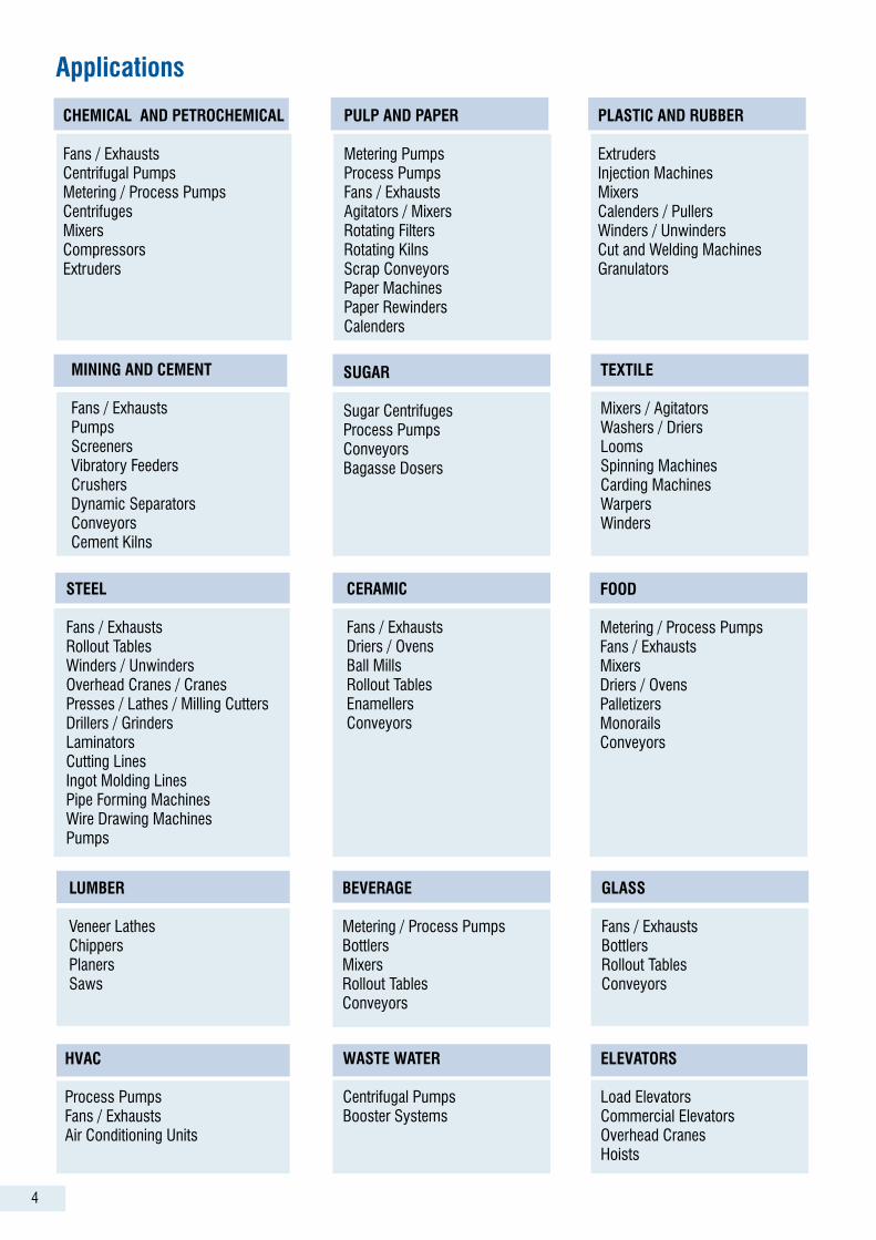
CHEMICAL AND PETROCHEMICAL
Fans / ExhaustsCentrifugal PumpsMetering / Process PumpsCentrifugesMixersCompressorsExtruders
PULP AND PAPER
Metering PumpsProcess PumpsFans / ExhaustsAgitators / MixersRotating FiltersRotating KilnsScrap ConveyorsPaper MachinesPaper RewindersCalenders
STEEL
Fans / ExhaustsRollout TablesWinders / UnwindersOverhead Cranes / CranesPresses / Lathes / Milling CuttersDrillers / GrindersLaminatorsCutting LinesIngot Molding LinesPipe Forming MachinesWire Drawing MachinesPumps
Applications
PLASTIC AND RUBBER
ExtrudersInjection MachinesMixersCalenders / PullersWinders / UnwindersCut and Welding MachinesGranulators
MINING AND CEMENT
Fans / ExhaustsPumpsScreenersVibratory FeedersCrushersDynamic SeparatorsConveyorsCement Kilns
SUGAR
Sugar CentrifugesProcess PumpsConveyorsBagasse Dosers
TEXTILE
Mixers / AgitatorsWashers / DriersLoomsSpinning MachinesCarding MachinesWarpersWinders
HVAC
Process PumpsFans / ExhaustsAir Conditioning Units
FOOD
Metering / Process PumpsFans / ExhaustsMixersDriers / OvensPalletizersMonorailsConveyors
BEVERAGE
Metering / Process PumpsBottlersMixersRollout TablesConveyors
GLASS
Fans / ExhaustsBottlersRollout TablesConveyors
CERAMIC
Fans / ExhaustsDriers / OvensBall MillsRollout TablesEnamellersConveyors
WASTE WATER
Centrifugal PumpsBooster Systems
ELEVATORS
Load ElevatorsCommercial ElevatorsOverhead CranesHoists
LUMBER
Veneer LathesChippersPlanersSaws
5
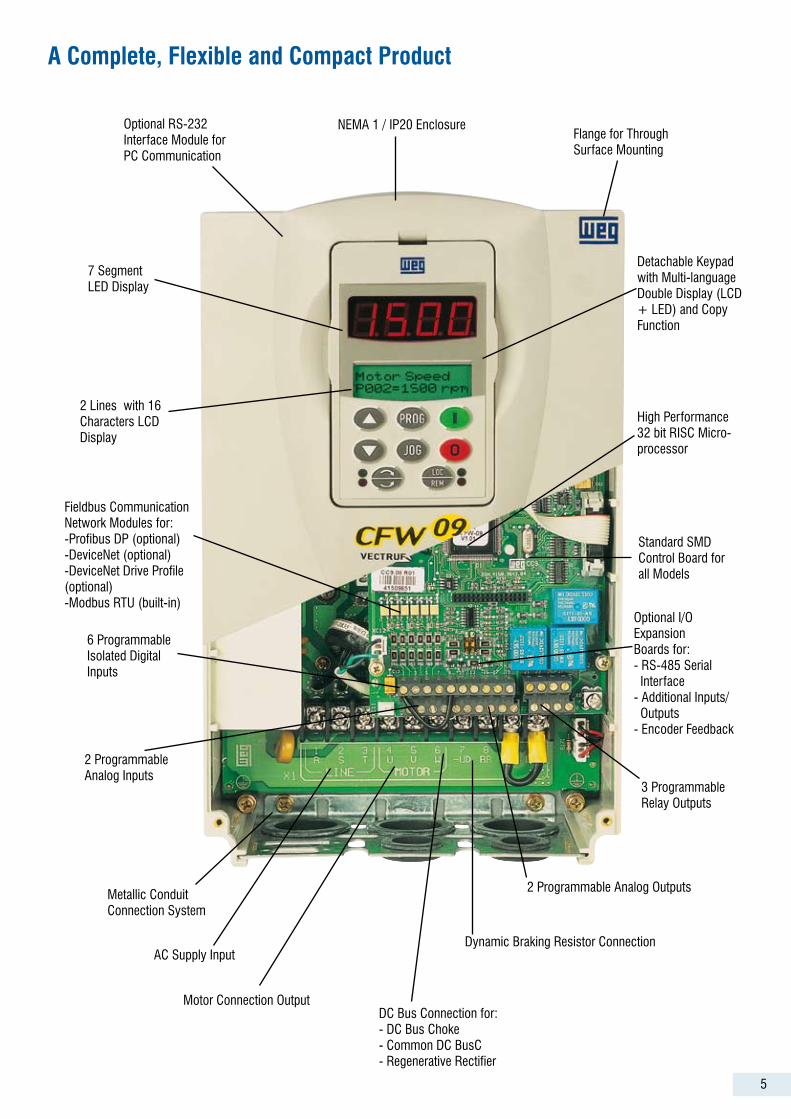
A Complete, Flexible and Compact Product
Optional RS-232 Interface Module for PC Communication
7 Segment LED Display
2 Lines with 16 Characters LCD Display
Fieldbus Communication Network Modules for:-Profibus DP (optional)-DeviceNet (optional)-DeviceNet Drive Profile (optional)-Modbus RTU (built-in)
Dynamic Braking Resistor Connection
2 Programmable Analog Outputs
3 Programmable Relay Outputs
Optional I/OExpansionBoards for:- RS-485 Serial Interface- Additional Inputs/ Outputs- Encoder Feedback
Standard SMD Control Board for all Models
High Performance 32 bit RISC Micro-processor
Detachable Keypad with Multi-language Double Display (LCD + LED) and Copy Function
Flange for Through Surface Mounting
NEMA 1 / IP20 Enclosure
6 Programmable Isolated Digital Inputs
2 Programmable Analog Inputs
Metallic Conduit Connection System
AC Supply Input
Motor Connection OutputDC Bus Connection for:- DC Bus Choke- Common DC BusC- Regenerative Rectifier
6
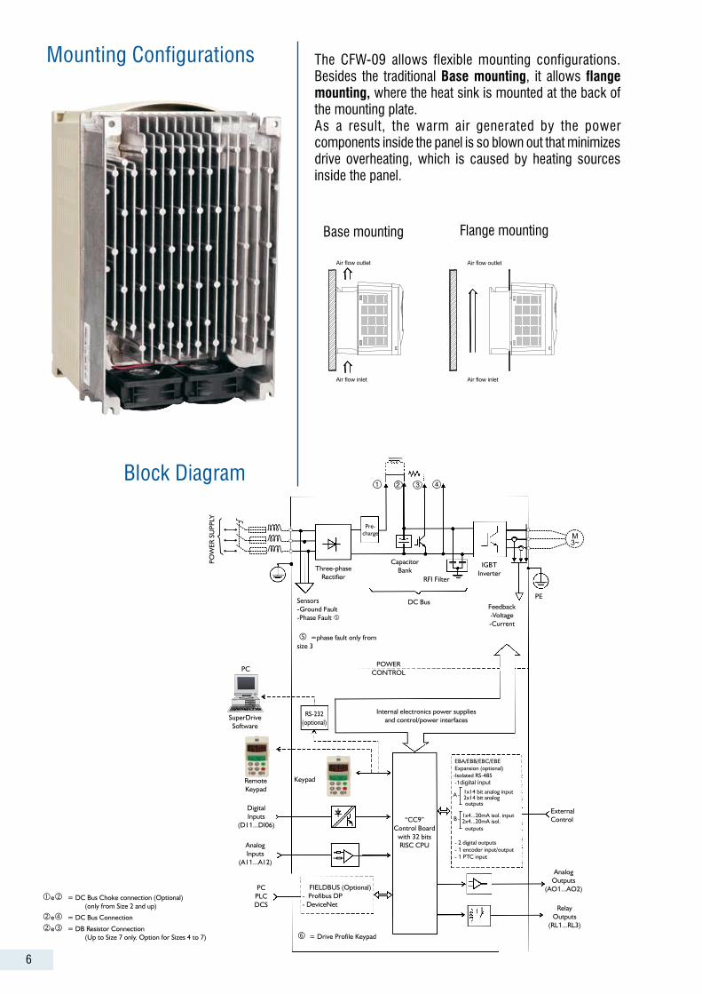
The CFW-09 allows flexible mounting configurations. Besides the traditional Base mounting, it allows flange mounting, where the heat sink is mounted at the back of the mounting plate.As a result, the warm air generated by the power components inside the panel is so blown out that minimizes drive overheating, which is caused by heating sources inside the panel.
Mounting Configurations
Block Diagram
e =DCBusChokeconnection(Optional) (onlyfromSize2andup)
e=DCBusConnection
e=DBResistorConnection (UptoSize7only.OptionforSizes4to7)
Three-phaseRectifier
Sensors-GroundFault-PhaseFault
=phasefaultonlyfromsize3
DCBus
CapacitorBank
RFIFilter
IGBTInverter
Feedback-Voltage-Current
PE
Pre-charge
RS-232(optional)
SuperDriveSoftware
Internalelectronicspowersuppliesandcontrol/powerinterfaces
“CC9”ControlBoard
with32bitsRISCCPU
EBA/EBB/EBC/EBEExpansion(optional)-IsolatedRS-485-1digital input1x14bitanaloginput2x14bitanalogoutputs
1x4...20mAisol.input2x4...20mAisol.outputs
-2digitaloutputs-1encoderinput/output-1PTCinput
RemoteKeypad
DigitalInputs
(D11...DI06)
AnalogInputs
(A11...A12)
PCPLCDCS
FIELDBUS(Optional)-ProfibusDP-DeviceNet
AnalogOutputs
(AO1...AO2)
RelayOutputs
(RL1...RL3)
ExternalControl
PCPOWER
CONTROL
POW
ERS
UPP
LY
Keypad
Base mounting Flange mounting
A
B
Air flow inlet
Air flow outlet
Air flow inlet
Air flow outlet
�=DriveProfileKeypad

7
Intelligent Keypad Intelligent operating interface with double display, LED (7 segment) and LCD (2 lines with 16 characters), providing optimum distant viewing along with a detailed description of all parameters and messages.
Selectable LanguageThe intelligent operation interface also allows the product user to choose, for his comfort, the language to be used in programming, reading and presenting the parameters and alphanumerical messages through the LCD display.The product’s high hardware and software capacity enables the user to use various languages such as Portuguese, English and Spanish so as to make it adaptable for users throughout the world.
Oriented Start-up Frequency inver ters are equipment for activating induction motors, the adaptation and performance of which are directly related to its characteristics as well as to the power source network. The CFW-09 line inverters have a built-in programming capability which has been specially developed for the purpose of making easy and speeding up the star t-up of the product, according to a guided and automatic sequence which leads the user through the sequential introduction of the minimum characteristics required for perfect adaptation of the inverter to the activated motor.
COPY Function This intelligent keypad also incorporates a “Copy Function”, which allows copying parameters from one drive to others, providing easy and reliable programming repeatability for duplicate applications.
LED Display
LCD Display
“LOCAL” LED“REMOTE” LED
“FORWARD” LED
“REVERSE” LED
Inverter “A” Inverter “B”
CFW-09 Keypad Keypad CFW-09
Keypad
8
SuperDriveprogramming Software
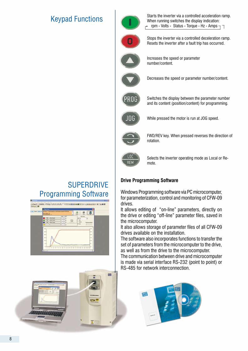
Drive Programming Software
Windows Programming software via PC microcomputer, for parameterization, control and monitoring of CFW-09 drives.It allows editing of “on-line” parameters, directly on the drive or editing “off-line” parameter files, saved in the microcomputer.It also allows storage of parameter files of all CFW-09 drives available on the installation.The software also incorporates functions to transfer the set of parameters from the microcomputer to the drive, as well as from the drive to the microcomputer.The communication between drive and microcomputer is made via serial interface RS-232 (point to point) or RS-485 for network interconnection.
Keypad Functions Starts the inverter via a controlled acceleration ramp. When running switches the display indication: rpm - Volts - Status - Torque - Hz - Amps
Stops the inverter via a controlled deceleration ramp. Resets the inverter after a fault trip has occurred.
Increases the speed or parameter number/content.
Decreases the speed or parameter number/content.
Switches the display between the parameter number and its content (position/content) for programming.
While pressed the motor is run at JOG speed.
FWD/REV key. When pressed reverses the direction of rotation.
Selects the inverter operating mode as Local or Re-mote.
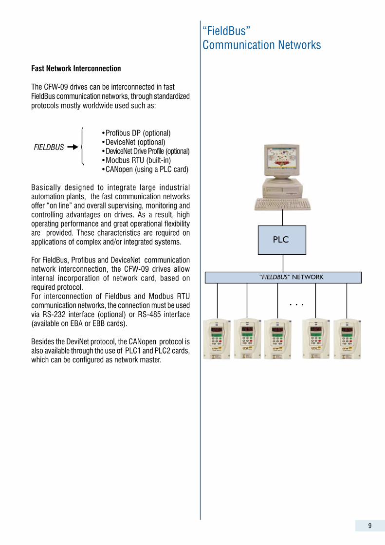
“FieldBus” Communication Networks
PLC
“FIELDBUS”NETWORK
...
9
Fast Network Interconnection
The CFW-09 drives can be interconnected in fastFieldBus communication networks, through standardized protocols mostly worldwide used such as:
•Profibus DP (optional) •DeviceNet (optional) •DeviceNet Drive Profile (optional) •Modbus RTU (built-in) •CANopen (using a PLC card)
Basically designed to integrate large industrial automation plants, the fast communication networks offer “on line” and overall supervising, monitoring and controlling advantages on drives. As a result, high operating performance and great operational flexibility are provided. These characteristics are required on applications of complex and/or integrated systems.
For FieldBus, Profibus and DeviceNet communication network interconnection, the CFW-09 drives allow internal incorporation of network card, based on required protocol.For interconnection of Fieldbus and Modbus RTU communication networks, the connection must be used via RS-232 interface (optional) or RS-485 interface (available on EBA or EBB cards).
Besides the DeviNet protocol, the CANopen protocol is also available through the use of PLC1 and PLC2 cards, which can be configured as network master.
FIELDBUS

10
Common DC Bus Configuration
Regenerative Drive
A Regenerative Drive can be implemented connecting the DC Bus of a standard CFW-09 to the output of a CFW-09-RB Regenerative Rectifier Unit.This solution provides line regenerative braking capabil-ity and input power factor near 1.0Such a drive configuration is recommended for applica-tion with cyclic braking duty, extremely short braking times and high dynamic performance requirements, such as: Paper Re-winders, Centrifuges, Cranes, etc.Besides the advantages mentioned above, this option eliminates harmonics at drive inlet and it is suitable for applications where current harmonic distortions on the power supply are not allowed.
The CFW-09 inverters have DC Bus access allowing the implementation of applications that require a Common DC Bus Configuration as well as Regenerative Systems.
Common DC Bus
Used in multi-motor drive systems where the individual rectifier bridges are replaced by a common input rectifier unit and the multiple drives are fed directly to their DC Buses in a parallel configuration.This solution allows energy transfer between the inverter units, optimizing the power consumption from the system.
Common input rectifier unit
Power Supply Common DC Bus
CFW-09 - HD
1 234 n
Regenerative Drive
RegenerativeRectifier UnitCFW-09 - RB
CFW-09 - HDInverter
DC Bus
Power Supply (illustrative photo)
11
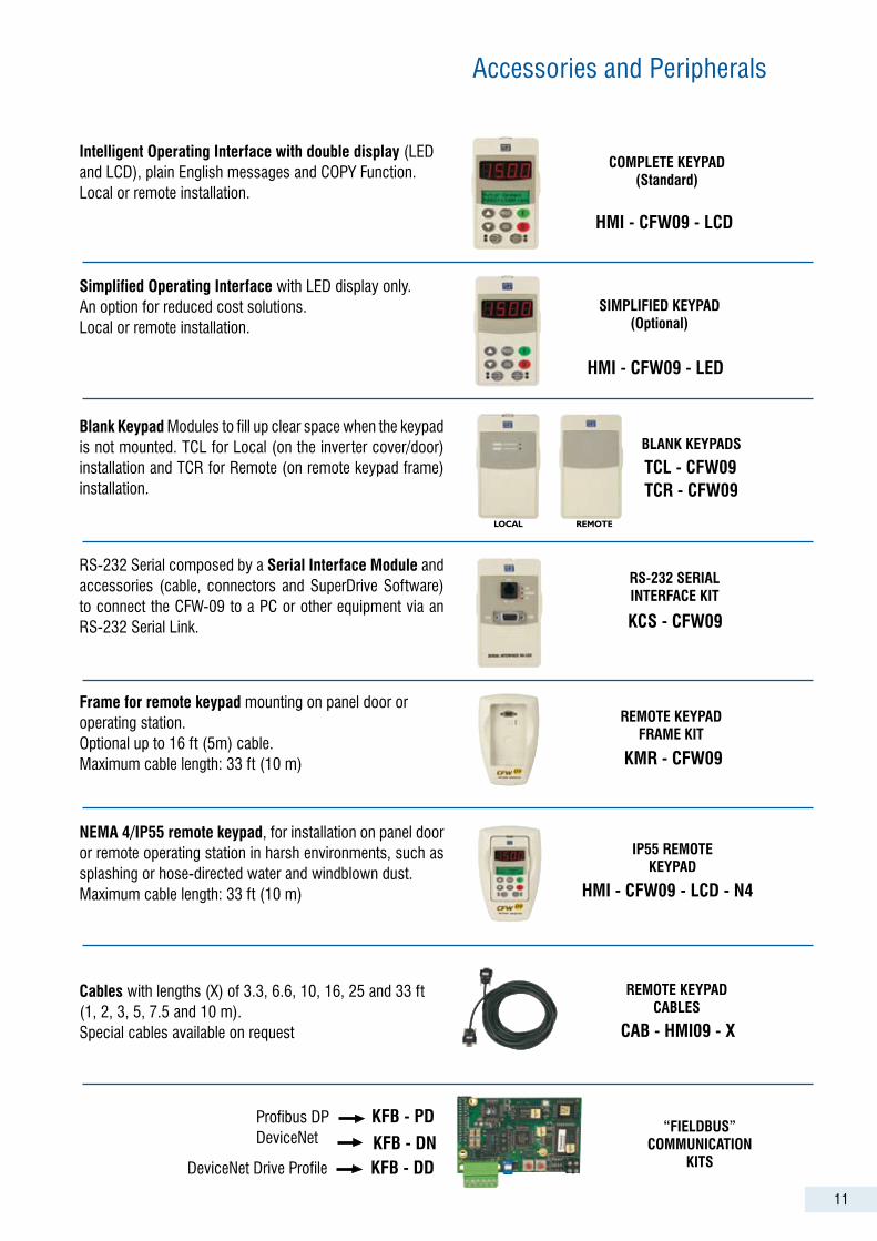
Simplified Operating Interface with LED display only. An option for reduced cost solutions.Local or remote installation.
SIMPLIFIED KEYPAD(Optional)
HMI - CFW09 - LED
Blank Keypad Modules to fill up clear space when the keypad is not mounted. TCL for Local (on the inverter cover/door) installation and TCR for Remote (on remote keypad frame) installation.
BLANK KEYPADS
TCR - CFW09TCL - CFW09
RS-232 Serial composed by a Serial Interface Module and accessories (cable, connectors and SuperDrive Software) to connect the CFW-09 to a PC or other equipment via an RS-232 Serial Link.
RS-232 SERIAL INTERFACE KIT
KCS - CFW09
Frame for remote keypad mounting on panel door or operating station.Optional up to 16 ft (5m) cable.Maximum cable length: 33 ft (10 m)
REMOTE KEYPADFRAME KIT
KMR - CFW09
NEMA 4/IP55 remote keypad, for installation on panel door or remote operating station in harsh environments, such as splashing or hose-directed water and windblown dust.Maximum cable length: 33 ft (10 m)
IP55 REMOTEKEYPAD
HMI - CFW09 - LCD - N4
Cables with lengths (X) of 3.3, 6.6, 10, 16, 25 and 33 ft (1, 2, 3, 5, 7.5 and 10 m).Special cables available on request
“FIELDBUS”COMMUNICATION
KITS
LOCAL REMOTE
CAB - HMI09 - X
REMOTE KEYPADCABLES
KFB - PD
KFB - DN
COMPLETE KEYPAD(Standard)
HMI - CFW09 - LCD
Intelligent Operating Interface with double display (LED and LCD), plain English messages and COPY Function.Local or remote installation.
Accessories and peripherals
Profibus DPDeviceNet
DeviceNet Drive Profile KFB - DD
12
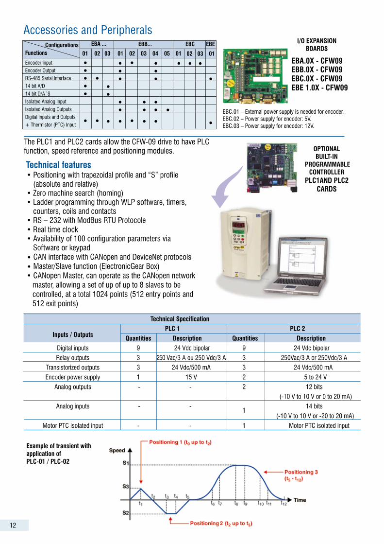
The PLC1 and PLC2 cards allow the CFW-09 drive to have PLC function, speed reference and positioning modules.
• Positioning with trapezoidal profile and “S” profile (absolute and relative)• Zero machine search (homing)• Ladder programming through WLP software, timers, counters, coils and contacts• RS – 232 with ModBus RTU Protocole• Real time clock• Availability of 100 configuration parameters via Software or keypad• CAN interface with CANopen and DeviceNet protocols• Master/Slave function (ElectronicGear Box)• CANopen Master, can operate as the CANopen network master, allowing a set of up of up to 8 slaves to be controlled, at a total 1024 points (512 entry points and 512 exit points)
Technical features
I/O EXPANSIONBOARDS
EBB.0X - CFW09EBC.0X - CFW09EBE 1.0X - CFW09
EBA.0X - CFW09
PLC1AND PLC2 CARDS
Example of transient with application of PLC-01 / PLC-02
OPTIONALBUILT-IN
PROGRAMMABLE CONTROLLER
EBC.01 – External power supply is needed for encoder.EBC.02 – Power supply for encoder: 5V.EBC.03 – Power supply for encoder: 12V.
Accessories and peripherals
Technical Specification PLC 1 PLC 2 Inputs / Outputs Quantities Description Quantities Description Digital inputs 9 24 Vdc bipolar 9 24 Vdc bipolar
Relay outputs 3 250 Vac/3 A ou 250 Vdc/3 A 3 250Vac/3 A or 250Vdc/3 A
Transistorized outputs 3 24 Vdc/500 mA 3 24 Vdc/500 mA
Encoder power supply 1 15 V 2 5 to 24 V
Analog outputs - - 2 12 bits
(-10 V to 10 V or 0 to 20 mA)
Analog inputs - - 14 bits
1
(-10 V to 10 V or -20 to 20 mA)
Motor PTC isolated input - - 1 Motor PTC isolated input
•••••
•
•••
•••
•
•
••
•
•
•
•••
01 02 03 01 02 03 04 05 01
EBA ... EBB...
•••
•••
•
EBC EBE
•02 03 01
• •
•
•
Encoder Input
Encoder Output
RS-485 Serial Interface
14 bit A/D
14 bit D/A´S
Isolated Analog Input
Isolated Analog Outputs
Digital Inputs and Outputs
+ Thermistor (PTC) Input
FunctionsConfigurations
13
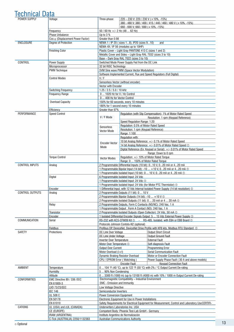
POWER SUPPLY Voltage Three-phase: 220 – 230 V: 220 / 230 V (+10%, -15%) 380 - 480 V: 380 / 400 / 415 / 440 / 460 / 480 V (+10%, -15%) 660 - 690 V; 660 / 690 (+10%, -15%) Frequency 50 / 60 Hz +/- 2 Hz (48 ... 62 Hz) Phase Unbalance Up to 3 % Cos ϕ (Displacement Power Factor) Greater than 0.98 ENCLOSURE Degree of Protection NEMA 1 / IP 20 ( sizes 1...8), IP20 (sizes 9...10) and NEMA 4X / IP 56 (modules up to 10HP) Finishing Color Plastic Cover – Light Gray PANTONE 413 C (sizes 1 and 2) Metallic Cover and Sides – Light Gray RAL 7032 (sizes 3 to 10) Base – Dark Gray RAL 7022 (sizes 3 to 10) CONTROL Power Supply Switched Mode Power Supply Fed from the DC Link Microprocessor 32 bit RISC Technology PWM Technique SVM Sine wave PWM (Space Vector Modulation) Software Implemented Current, Flux and Speed Regulators (Full Digital) Control Modes V / F Sensorless Vector (without encoder) Vector with Encoder Switching Frequency 1.25 / 2.5 / 5.0 / 10 kHz Frequency Range 0 ... 1020 Hz for V / Hz Control 0 ... 408 Hz for Vector Control Overload Capacity 150% for 60 seconds, every 10 minutes 180% for 1 second every 10 minutes Efficiency Greater than 97% PERFORMANCE Speed Control Regulation (with Slip Compensation): 1% of Motor Rated Speed Resolution: 1 rpm (Keypad Reference) Speed Regulation Range: 1:20 Regulation: 0.5% of Motor Rated Speed Resolution: 1 rpm (Keypad Reference) Range: 1:100 Regulation with: 10 bit Analog Reference: +/- 0.1% of Motor Rated Speed 14 bit Analog Reference: +/- 0.01% of Motor Rated Speed Digital Reference (Ex: Keypad or Serial): +/- 0.01% of Motor Rated Speed Range: Down to 0 rpm Torque Control Regulation: +/- 10% of Motor Rated Torque Range: 0 ... 150% of Motor Rated Torque CONTROL INPUTS Analog 2 Programmable Differential Inputs (10 bit): 0...10 V, 0...20 mA or 4...20 mA 1 Programmable Bipolar Input (14 bit): -10 ... +10 V, 0...20 mA or 4...20 mA 1 Programmable Isolated Input (10 bit): 0 ... 10 V, 0...20 mA or 4...20 mA Digital 6 Programmable Isolated Input: 24 Vdc 1 Programmable Isolated Input: 24 Vdc 1 Programmable Isolated Input: 24 Vdc (for Motor PTC Thermistor) Encoder 1 Differential Input, with 12 Vdc Internal Isolated Power Supply (14 bit resolution) CONTROL OUTPUTS Analog 2 Programmable Outputs (11 bit): 0 ... 10 V 2 Programmable Bipolar Outputs (14 bit): -10 ... +10 V 2 Programmable Isolated Outputs (11 bit): 0 ... 20 mA or 4 ... 20 mA Relay 2 Programmable Outputs, Form C Contacts (NO/NC): 240 Vac, 1 A 1 Programmable Output , Form A Contact (NO): 240 Vac, 1 A Transistor 2 Programmable Isolated Outputs (Open Collector): 24 Vdc, 50 mA Encoder 1 Isolated Differential Encoder Signals Output: 5 ... 15 Vdc External Power Supply COMMUNICATION Serial RS-232 with KCS-CFW09 Kit - RS-485, Isolated, with EBA or EBB Board
Protocolo Johnson Contols-N2 (optional) Fieldbus Profibus DP, DeviceNet, DeviceNet Drive Profile with KFB kits, Modbus RTU Standard SAFETY Protections DC Link Over Voltage Output Short Circuit DC Link Under Voltage Output Ground Fault Inverter Over Temperature External Fault Motor Over Temperature Self-diagnosis Fault Output Over Current Programming Error Motor Overload (i x t) Serial Communication Fault Dynamic Braking Resistor Overload Motor or Encoder Connection Fault CPU / EPROM Error ( Watchdog ) Power Supply Phase Fault ( 30 A and above models) Encoder Fault Keypad Connection Fault AMBIENT Temperature 0 ... 104 °F (40 °C), up to 122 °F (50 °C) with 2% / °C Output Current De-rating Humidity 5 ... 90% Non Condensing Altitude 0 ... 3300 ft (1000 m) (up to 13100 ft (4000 m) with 10% / 1000 m Output Current De-rating CONFORMITIES EMC Directive 89 / 336 /EEC EN 61800-3 LVD 73/23/EEC Low Voltage Directive IEC 146 Semiconductor Inverters UL 508 C Power Conversion Equipment EN 50178 Electronic Equipment for Use in Power Installations EN 61010 Safety Requirements for Electrical Equipment for Measurement, Control and Laboratory Use CERTIFI-CATIONS UL (USA) and cUL (CANADA) Underwriters Laboratories Inc. USA CE (EUROPE) Competent Body: Phoenix Test-Lab GmbH - Germany IRAM (ARGENTINA) Instituto Argentino de Normalización C-Tick (AUSTRALIA) 2250/1132383 Australian Communications Authority
V / F Mode
Sensorless Vector Mode
Encoder Vector Mode
Vector Modes
Electromagnetic Compatibility – Industrial EnvironmentEMC - Emission and Immunity
Optional
Technical Data
14
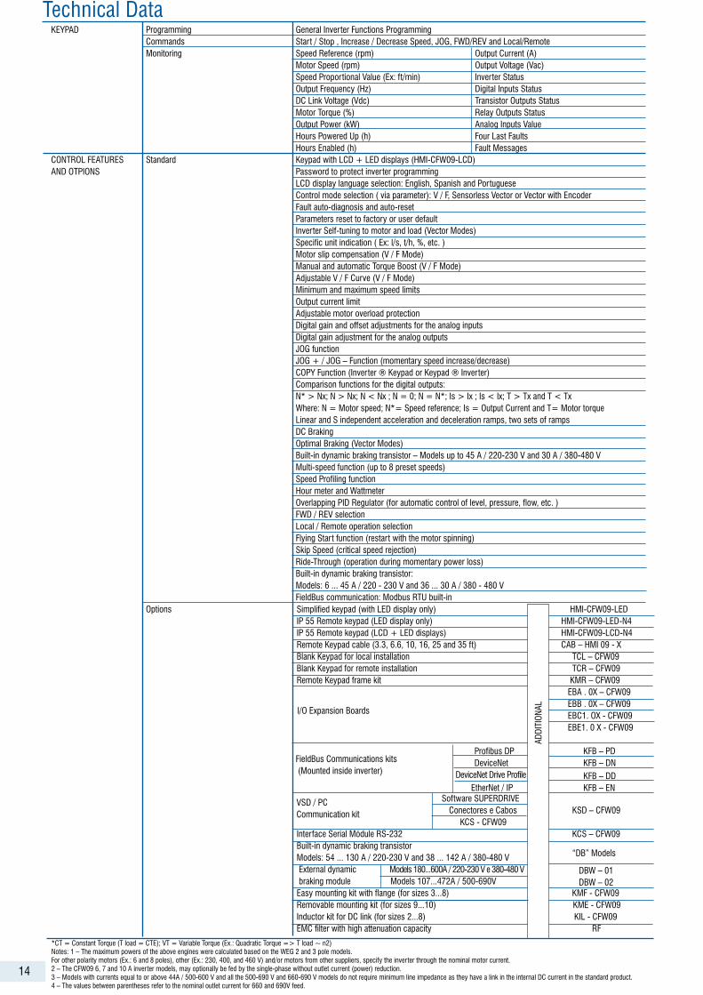
KEYPAD Programming General Inverter Functions Programming Commands Start / Stop , Increase / Decrease Speed, JOG, FWD/REV and Local/Remote Monitoring Speed Reference (rpm) Output Current (A) Motor Speed (rpm) Output Voltage (Vac) Speed Proportional Value (Ex: ft/min) Inverter Status Output Frequency (Hz) Digital Inputs Status DC Link Voltage (Vdc) Transistor Outputs Status Motor Torque (%) Relay Outputs Status Output Power (kW) Analog Inputs Value Hours Powered Up (h) Four Last Faults Hours Enabled (h) Fault Messages CONTROL FEATURES Standard Keypad with LCD + LED displays (HMI-CFW09-LCD) AND OTPIONS Password to protect inverter programming LCD display language selection: English, Spanish and Portuguese Control mode selection ( via parameter): V / F, Sensorless Vector or Vector with Encoder Fault auto-diagnosis and auto-reset Parameters reset to factory or user default Inverter Self-tuning to motor and load (Vector Modes) Specific unit indication ( Ex: l/s, t/h, %, etc. ) Motor slip compensation (V / F Mode) Manual and automatic Torque Boost (V / F Mode) Adjustable V / F Curve (V / F Mode) Minimum and maximum speed limits Output current limit Adjustable motor overload protection Digital gain and offset adjustments for the analog inputs Digital gain adjustment for the analog outputs JOG function JOG + / JOG – Function (momentary speed increase/decrease) COPY Function (Inverter ® Keypad or Keypad ® Inverter) Comparison functions for the digital outputs: N* > Nx; N > Nx; N < Nx ; N = 0; N = N*; Is > Ix ; Is < Ix; T > Tx and T < Tx Where: N = Motor speed; N*= Speed reference; Is = Output Current and T= Motor torque Linear and S independent acceleration and deceleration ramps, two sets of ramps DC Braking Optimal Braking (Vector Modes) Built-in dynamic braking transistor – Models up to 45 A / 220-230 V and 30 A / 380-480 V Multi-speed function (up to 8 preset speeds) Speed Profiling function Hour meter and Wattmeter Overlapping PID Regulator (for automatic control of level, pressure, flow, etc. ) FWD / REV selection Local / Remote operation selection Flying Start function (restart with the motor spinning) Skip Speed (critical speed rejection) Ride-Through (operation during momentary power loss) Built-in dynamic braking transistor: Models: 6 ... 45 A / 220 - 230 V and 36 ... 30 A / 380 - 480 V FieldBus communication: Modbus RTU built-in
Technical Data
Options Simplified keypad (with LED display only) HMI-CFW09-LED IP 55 Remote keypad (LED display only) HMI-CFW09-LED-N4 IP 55 Remote keypad (LCD + LED displays) HMI-CFW09-LCD-N4 Remote Keypad cable (3.3, 6.6, 10, 16, 25 and 35 ft) CAB – HMI 09 - X Blank Keypad for local installation TCL – CFW09 Blank Keypad for remote installation TCR – CFW09 Remote Keypad frame kit KMR – CFW09 EBA . 0X – CFW09 EBB . 0X – CFW09 EBC1. OX - CFW09 EBE1. 0 X - CFW09 Profibus DP KFB – PD DeviceNet KFB – DN DeviceNet Drive Profile Software SUPERDRIVE Conectores e Cabos KSD – CFW09 KCS - CFW09 Interface Serial Módule RS-232 KCS – CFW09 Built-in dynamic braking transistor Models: 54 ... 130 A / 220-230 V and 38 ... 142 A / 380-480 V External dynamic Models 180...600A / 220-230 V e 380-480 V braking module Models 107...472A / 500-690V Easy mounting kit with flange (for sizes 3...8) KMF - CFW09 Removable mounting kit (for sizes 9...10) KME - CFW09 Inductor kit for DC link (for sizes 2...8) KIL - CFW09 EMC filter with high attenuation capacity RF
ADDI
TION
AL
“DB” Models
DBW – 01 DBW – 02
EtherNet / IPKFB – DD KFB – EN
I/O Expansion Boards
FieldBus Communications kits (Mounted inside inverter)
VSD / PCCommunication kit
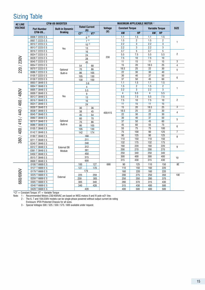
*CT = Constant Torque (T load = CTE); VT = Variable Torque (Ex.: Quadratic Torque => T load ~ n2)Notes: 1 – The maximum powers of the above engines were calculated based on the WEG 2 and 3 pole models.For other polarity motors (Ex.: 6 and 8 poles), other (Ex.: 230, 400, and 460 V) and/or motors from other suppliers, specify the inverter through the nominal motor current.2 – The CFW09 6, 7 and 10 A inverter models, may optionally be fed by the single-phase without outlet current (power) reduction.3 – Models with currents equal to or above 44A / 500-600 V and all the 500-690 V and 660-690 V models do not require minimum line impedance as they have a link in the internal DC current in the standard product. 4 – The values between parentheses refer to the nominal outlet current for 660 and 690V feed.
15
0100 T 6669 E S 100 127 690 90 125 110 150 8E 0127 T 6669 E S 127 179 110 150 160 220 0179 T 6669 E S 179 160 220 160 220 0225 T 6669 E S 225 259 200 275 250 350 10E 0259 T 6669 E S External 259 305 250 350 280 370 0305 T 6669 E S 305 340 280 370 315 430 0340 T 6669 E S 340 428 315 430 400 500 0428 T 6669 E S 428 400 500 400 500
230
400/415
6
7
10
13 16242845
54 68 70 86 86 105 105 130 130 150 3.6
45.59131624
30 36 38 45 45 54 60 70 70 86 86 105 105 130 142 174
180211240312361450515600
AC LINEVOLTAGE Part Number
CFW-09...
CFW-09 INVERTER
Built-in DynamicBraking
Rated Current(A)
CT* VT*
Voltage(V)
MAXIMUM APPLICABLE MOTOR
Constant Torque Variable Torque SIZE
kW HP kW HP
Sizing Table38
0 / 4
00 /
415
/ 440
/ 46
0 / 4
80V
220
/ 230
V
0006 T 2223 E S 0007 T 2223 E S 0010 T 2223 E S 0013 T 2223 E S 0016 T 2223 E S 0024 T 2223 E S 0028 T 2223 E S 0045 T 2223 E S 0054 T 2223 E S 0070 T 2223 E S 0086 T 2223 E S 0105 T 2223 E S0130 T 2223 E S0003 T 3848 E S 0004 T 3848 E S 0005 T 3848 E S 0009 T 3848 E S 0013 T 3848 E S 0016 T 3848 E S 0024 T 3848 E S 0030 T 3848 E S 0038 T 3848 E S 0045 T 3848 E S 0060 T 3848 E S 0070 T 3848 E S 0086 T 3848 E S 0105 T 3848 E S 0142 T 3848 E S 0180 T 3848 E S 0211 T 3848 E S 0240 T 3848 E S 0312 T 3848 E S0361 T 3848 E S 0450 T 3848 E S0515 T 3848 E S 0600 T 3848 E S
Yes
OptionalBuilt-in
Yes
OptionalBuilt-in
External DBModule
1.1 1.5 1.1 1.5 1.5 2 1.5 2 2.2 3 2.2 3 2.2 3 2.2 3 3.7 5 3.7 5 5.5 7.5 5.5 5.5 7.5 10 7.5 10 11 15 11 15 15 20 18.5 25 18.5 25 22 30 22 30 30 40 30 40 37 50 37 50 45 60 1.1 1.5 1.1 1.5 1.5 2 1.5 2 2.2 3 2.2 3 4 5.5 4 5.5 5.5 7.5 5.5 7.5 7.5 10 7.5 10 11 15 11 15 15 20 18.5 25 18.5 25 22 30 22 30 22 30 30 40 37 50 37 50 45 60 45 60 55 75 55 75 75 100 75 100 90 125 90 125 90 125 110 150 110 150 132 175 132 175 160 220 160 220 200 270 200 270 250 340 250 340 300 400 300 400 315 430 315 430
1
2
34
5
6
1
2
3
4
5
6
7
8
9
10
*CT = Constant Torque; VT = Variable TorqueNote: 1 - Recommended Motors 230/400VAC are based on WEG motors II and IV pole w21 line. 2 - The 6, 7 and 10A/230V models can be single-phase powered without output current de-rating Enclosure: IP20 Protected Chassis for all sizes. 3 - Special Voltages 500 / 525 / 550 / 575 / 600 available under request.
660/
690V
17
CFW-09 part Number Specification
CFW09 0016 T 3848 E O 00 SI DB A1 DN H1 S3 Z
5 6 7 8 11 121 2
3 4 9 10 13 14
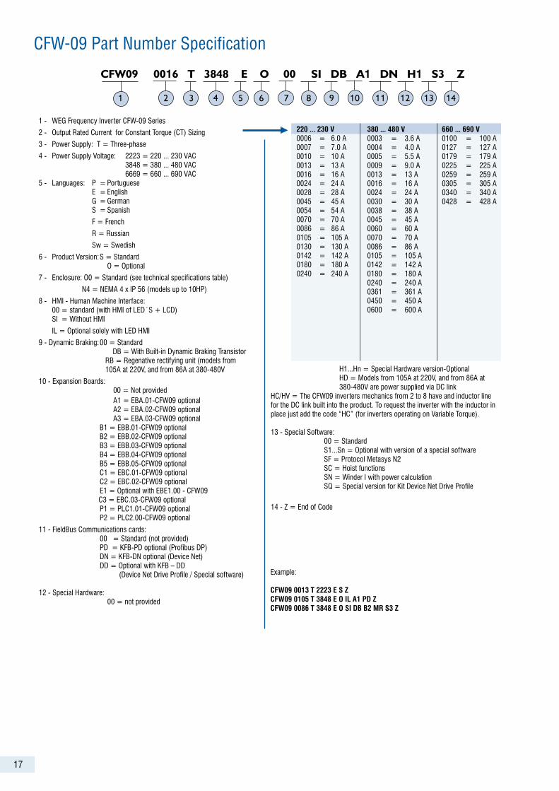
380 ... 480 V 0003 = 3.6 A 0004 = 4.0 A 0005 = 5.5 A 0009 = 9.0 A 0013 = 13 A 0016 = 16 A 0024 = 24 A 0030 = 30 A 0038 = 38 A 0045 = 45 A 0060 = 60 A 0070 = 70 A 0086 = 86 A 0105 = 105 A 0142 = 142 A 0180 = 180 A 0240 = 240 A 0361 = 361 A 0450 = 450 A 0600 = 600 A
220 ... 230 V 0006 = 6.0 A 0007 = 7.0 A 0010 = 10 A 0013 = 13 A 0016 = 16 A 0024 = 24 A 0028 = 28 A 0045 = 45 A 0054 = 54 A 0070 = 70 A 0086 = 86 A 0105 = 105 A 0130 = 130 A 0142 = 142 A 0180 = 180 A 0240 = 240 A
660 ... 690 V 0100 = 100 A 0127 = 127 A 0179 = 179 A 0225 = 225 A 0259 = 259 A 0305 = 305 A 0340 = 340 A 0428 = 428 A
Example:
CFW09 0013 T 2223 E S ZCFW09 0105 T 3848 E O IL A1 PD ZCFW09 0086 T 3848 E O SI DB B2 MR S3 Z
1 - WEG Frequency Inverter CFW-09 Series
2 - Output Rated Current for Constant Torque (CT) Sizing
3 - Power Supply: T = Three-phase
4 - Power Supply Voltage: 2223 = 220 ... 230 VAC 3848 = 380 ... 480 VAC 6669 = 660 ... 690 VAC5 - Languages: P = Portuguese E = English G = German S = Spanish
F = French
R = Russian
Sw = Swedish
6 - Product Version: S = Standard O = Optional
7 - Enclosure: O0 = Standard (see technical specifications table)
N4 = NEMA 4 x IP 56 (models up to 10HP)
8 - HMI - Human Machine Interface: 00 = standard (with HMI of LED´S + LCD) SI = Without HMI
IL = Optional solely with LED HMI
9 - Dynamic Braking: 00 = Standard DB = With Built-in Dynamic Braking Transistor RB = Regenative rectifying unit (models from 105A at 220V, and from 86A at 380-480V
10 - Expansion Boards: 00 = Not provided A1 = EBA.01-CFW09 optional A2 = EBA.02-CFW09 optional A3 = EBA.03-CFW09 optional B1 = EBB.01-CFW09 optional B2 = EBB.02-CFW09 optional B3 = EBB.03-CFW09 optional B4 = EBB.04-CFW09 optional B5 = EBB.05-CFW09 optional C1 = EBC.01-CFW09 optional C2 = EBC.02-CFW09 optional E1 = Optional with EBE1.00 - CFW09 C3 = EBC.03-CFW09 optional P1 = PLC1.01-CFW09 optional P2 = PLC2.00-CFW09 optional
11 - FieldBus Communications cards: 00 = Standard (not provided) PD = KFB-PD optional (Profibus DP) DN = KFB-DN optional (Device Net) DD = Optional with KFB – DD (Device Net Drive Profile / Special software)
12 - Special Hardware: 00 = not provided
H1...Hn = Special Hardware version-Optional HD = Models from 105A at 220V, and from 86A at 380-480V are power supplied via DC linkHC/HV = The CFW09 inverters mechanics from 2 to 8 have and inductor line for the DC link built into the product. To request the inverter with the inductor in place just add the code “HC” (for inverters operating on Variable Torque).
13 - Special Software: 00 = Standard S1...Sn = Optional with version of a special software SF = Protocol Metasys N2 SC = Hoist functions SN = Winder I with power calculation SQ = Special version for Kit Device Net Drive Profile
14 - Z = End of Code
18
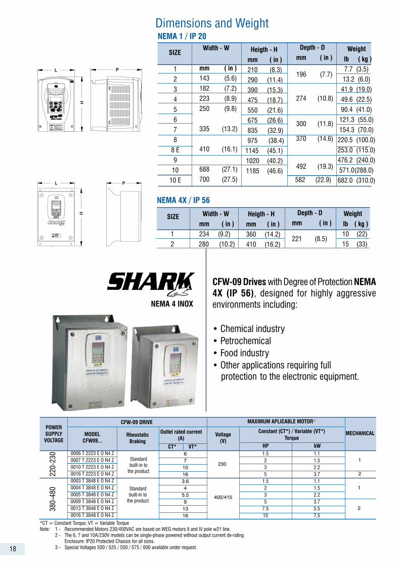
CFW-09 Drives with Degree of Protection NEMA 4X (IP 56), designed for highly aggressive environments including:
• Chemical industry• Petrochemical• Food industry• Other applications requiring full protection to the electronic equipment.
230
6710163.64
5.591316
POWERSUPPLYVOLTAGE
MODELCFW09...
CFW-09 DRIVE
RheostaticBraking
Outlet rated current(A)
CT* VT*
Voltage(V)
MAXIMUM APLICABLE MOTOR
Constant (CT*) / Variable (VT*)Torque
MECHANICAL
HP kW
220-
230 0006 T 2223 E O N4 Z
0007 T 2223 E O N4 Z0010 T 2223 E O N4 Z0016 T 2223 E O N4 Z0003 T 3848 E O N4 Z0004 T 3848 E O N4 Z0005 T 3848 E O N4 Z0009 T 3848 E O N4 Z0013 T 3848 E O N4 Z0016 T 3848 E O N4 Z
Standardbuilt-in to
the product
1.5 1.1 2 1.5 3 2.2 5 3.7 1.5 1.1 2 1.5 3 2.2 5 3.7 7.5 5.5 10 7.5
1
2
Standardbuilt-in to
the product 400/415
380-
480 1
2
1
2
Heigth - H mm ( in ) 360 (14.2)
410 (16.2)
Depth - D mm ( in )
221 (8.5)
Weight lb ( kg ) 10 (22)
15 (33)
Width - W mm ( in ) 234 (9.2)
280 (10.2)
NEMA 4X / IP 56
SIZE
Dimensions and Weight
1
2
3
4
5
6
7
8
8 E
9
10
10 E
Depth - D mm ( in )
196 (7.7)
274 (10.8)
300 (11.8)
370 (14.6)
492 (19.3)
582 (22.9)
Heigth - H mm ( in ) 210 (8.3)
290 (11.4)
390 (15.3)
475 (18.7)
550 (21.6)
675 (26.6)
835 (32.9)
975 (38.4)
1145 (45.1)
1020 (40.2)
1185 (46.6)
Width - W
mm ( in ) 143 (5.6)
182 (7.2)
223 (8.9)
250 (9.8)
335 (13.2)
410 (16.1)
688 (27.1)
700 (27.5)
NEMA 1 / IP 20
Weight lb ( kg ) 7.7 (3.5)
13.2 (6.0)
41.9 (19.0)
49.6 (22.5)
90.4 (41.0)
121.3 (55.0)
154.3 (70.0)
220.5 (100.0)
253.0 (115.0)
476.2 (240.0)
571.0(288.0)
682.0 (310.0)
SIZE
*CT = Constant Torque; VT = Variable TorqueNote: 1 - Recommended Motors 230/400VAC are based on WEG motors II and IV pole w21 line. 2 - The 6, 7 and 10A/230V models can be single-phase powered without output current de-rating Enclosure: IP20 Protected Chassis for all sizes. 3 - Special Voltages 500 / 525 / 550 / 575 / 600 available under request.
19
24VDC
M3~
EDI 4
EDI 5EDI 6
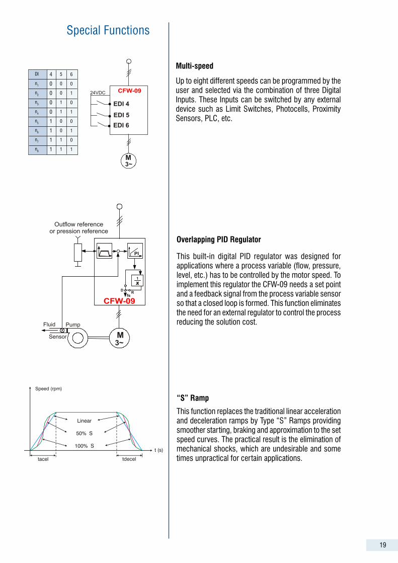
This function replaces the traditional linear acceleration and deceleration ramps by Type “S” Ramps providing smoother starting, braking and approximation to the set speed curves. The practical result is the elimination of mechanical shocks, which are undesirable and some times unpractical for certain applications.
Overlapping PID Regulator
Up to eight different speeds can be programmed by the user and selected via the combination of three Digital Inputs. These Inputs can be switched by any external device such as Limit Switches, Photocells, Proximity Sensors, PLC, etc.
“S” Ramp
Multi-speed
This built-in digital PID regulator was designed for applications where a process variable (flow, pressure, level, etc.) has to be controlled by the motor speed. To implement this regulator the CFW-09 needs a set point and a feedback signal from the process variable sensor so that a closed loop is formed. This function eliminates the need for an external regulator to control the process reducing the solution cost.
Special Functions
DI
n1
n2
n3
n4
n5
n6
n7
n8
4
0
0
0
0
1
1
1
1
5
0
0
1
1
0
0
1
1
6
0
1
0
1
0
1
0
1
Speed (rpm)
Linear
50% S
100% S
tacel tdecel
t (s)
E02
Time
20
Special Functions
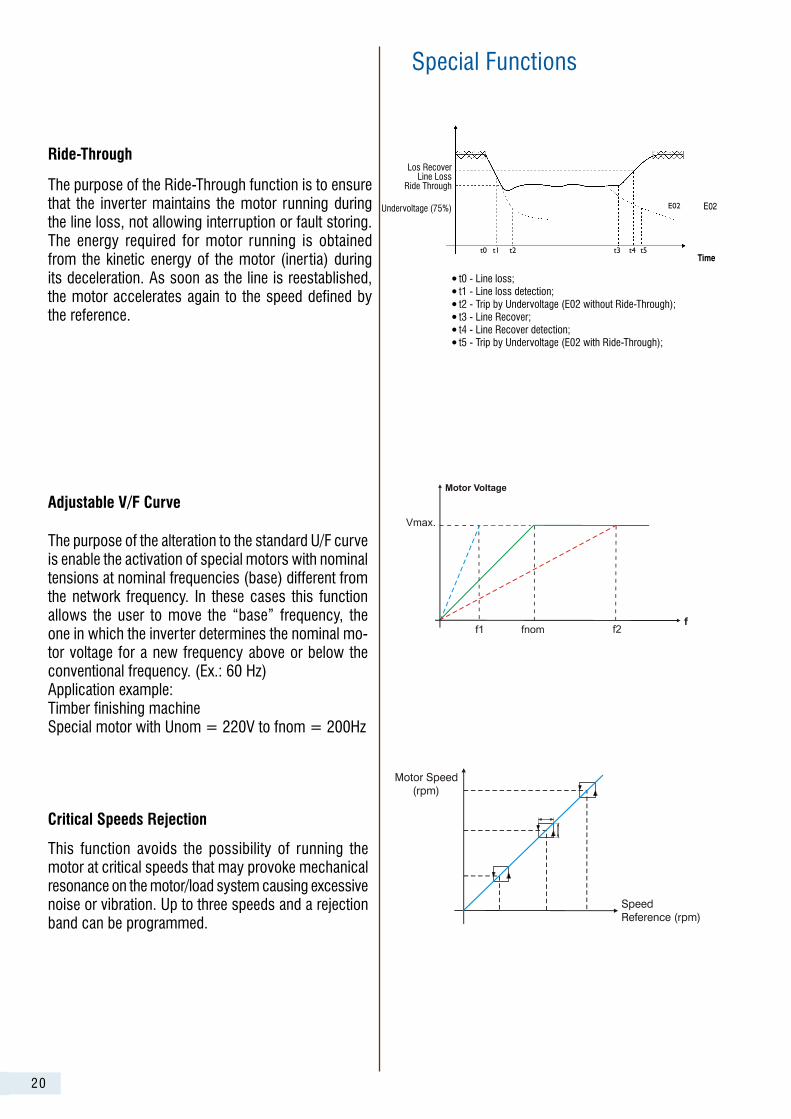
Ride-Through
The purpose of the Ride-Through function is to ensure that the inverter maintains the motor running during the line loss, not allowing interruption or fault storing. The energy required for motor running is obtained from the kinetic energy of the motor (inertia) during its deceleration. As soon as the line is reestablished, the motor accelerates again to the speed defined by the reference.
Adjustable V/F Curve
The purpose of the alteration to the standard U/F curve is enable the activation of special motors with nominal tensions at nominal frequencies (base) different from the network frequency. In these cases this function allows the user to move the “base” frequency, the one in which the inverter determines the nominal mo-tor voltage for a new frequency above or below the conventional frequency. (Ex.: 60 Hz)Application example:Timber finishing machineSpecial motor with Unom = 220V to fnom = 200Hz
Critical Speeds Rejection
This function avoids the possibility of running the motor at critical speeds that may provoke mechanical resonance on the motor/load system causing excessive noise or vibration. Up to three speeds and a rejection band can be programmed.
Los Recover Line Loss
Ride Through
Undervoltage (75%)
t0t1t2 t3 t4 t5
E02
t0 - Line loss;t1 - Line loss detection;t2 - Trip by Undervoltage (E02 without Ride-Through);t3 - Line Recover;t4 - Line Recover detection;t5 - Trip by Undervoltage (E02 with Ride-Through);

847.
13/1
1.20
06
Note: please visit our website (www.weg.net) and look for WEG’s nearest branch office or representative.