variable displacement pump aa11vo - airline hydraulics · 1 brueninghaus hydromatik nominal...
TRANSCRIPT

1
Brueninghaus Hydromatik Nominal Pressure Peak Pressure
RA92500/08.97
replaces 01.96
Variable Displacement Pump AA11VOSeries 1, for Open CircuitsAxial Piston, Swashplate Design
Sizes 40...260
RA 92500/08.97
5100 psi(350 bar)
5800 psi(400 bar)
The AA11VO is a swashplate design, variable displace-ment axial piston pump for use in open circuit hydraulicsystems.
Designed principally for use in mobile applications.
The pump operates under self-priming condition, with tankpressurization, or with charge pump (impeller).
A complete range of control and regulating devices isavailable.
The constant power control is externally adjustable, evenwhen the pump is operating.
The pump is available with a through drive to accept a gearpump or a second axial piston pump up to the same size(100 % through drive).
Output flow is proportional to drive speed and pumpdisplacement and is infinitely variable between maximumand zero.
AA11VO 75

RA 92500/08.97
AA11V O / 1 – 62Axial piston unit
Charge pump
Mode of operation
Size
Control device
2-3
Series
1
Indexsizes 40...130 0sizes 190...260 1
Direction of rotation
viewed on shaft end clockwise R
counter-clockwise L
Seals
NBR (nitril-caoutchouc), shaft seal in FPM (fluor-caoutchouc) NFPM (fluor-caoutchouc) V
Shaft end 40 60 75 95 130 190 260
Splined shaft SAE standard for single pump Sstandard for combination pump –1) –1) T
Parallel with key DIN 6885 P1) Use shaft end S for combination pump
Mounting flange
SAE 2-bolt – – – – – C
SAE 4-bolt – – D
Service line connections 40 60 75 95 130 190 260
Pressure and suction port SAE on (opposite) side, 62
Through drive (assembly possibilities see page 30) 40 60 75 95 130 190 260
hub flange
– – N00
SAE A (N 5/8"-9T 16/32 DP) SAE A, 2-bolt K01
SAE B (N 7/8"-13T 16/32 DP) SAE B, 2-bolt K02
SAE B-B (N 1"-15T 16/32 DP) SAE B, 2-bolt K04
SAE C (N 1 1/4"-14T 12/24 DP) SAE C, 2-bolt – K07
SAE C (N 1 1/4"-14T 12/24 DP) SAE D, 4-bolt – – K86
SAE C-C (N 1 1/2"-17T 12/24 DP) SAE C, 2-bolt – – – K24
SAE D (N 1 3/4"-13T 8/16 DP) SAE D, 4-bolt – – – – K17
SAE D (N 1 3/4"-13T 8/16 DP) SAE E, 4-bolt – – – – – K72
Swivel angle indicator
Without swivel angle indicator (no code)Optical swivel angle indicator VElectronical swivel angle indicator E
Variable Displacement Pump AA11VO
Ordering Code
= available= in preparation, available on enquiry
– = not available
1) Technical specifications see page 5
Hydraulic fluidPetroleum oil (no code)
Axial piston unit
Variable swashplate design AA11V
Charge pump (impeller) 1) 40 60 75 95 130 190 260
without charge pump (no code)
with charge pump – – – – L
Mode of operation
Pump in open circuit O
Size
Size 40 60 75 95 130 190 260
Displacement Vg max cm3/rev. 42 58,3 74 93,8 130 192,7 260
in3/rev. 2.56 3.56 4.52 5.72 7.93 11.76 15.87
Control device 40 60 75 95 130 190 260
Constant power control LR LRwith power influence, high pressure related LR3 LR3with load limiting control hydraulic override, negative LG1 LG1
with load limiting control hydraulic override, positive LG2 LG2
with load limiting control electric override 24V, negative LE2 LE2
with pressure cut-off D L . . D
with pressure cut-off, 2 stages E L . . E
with pressure cut-off, remote control G L . . G
with cross sensing control (flow control) C L . . C
with load sensing control S L . . S
with hydr. stroke limiter, neg. control, ∆p=365psi(25 bar) H1 L . . H1
with hydr. stroke limiter, neg. control, ∆p=145psi(10 bar) H5 L . . H5
with hydr. stroke limiter, pos. control, ∆p=365psi(25 bar) H2 L . . H2
with hydr. stroke limiter, pos. control, ∆p=145psi(10 bar) H6 L . . H6
with electrical stroke limiter 24V U2 L . . U2
Constant pressure control DR DR
remote control G DRG
for parallel operation L DRL
load sensing control (flow control) S ● ● ● ● ● ● ● DRS
Hydraulic control, pilot pressure related ∆p=145psi(10 bar) HD1 HD1
∆p=365psi(25 bar) HD2 HD2
pressure cut-off D HD . D
with remote pressure cut-off G HD . G
Electrical control with proportional solenoid 24 V EP2 EP2
pressure cut-off D EP2D
with remote pressure cut-off G EP2G
In case of controls with various additional functions take care of the sequence of the columns. For each column only 1 option is possible!

RA 92500/08.97
4
Variable Displacement Pump AA11VO
Vis
cosi
ty v
mm
2 /s (S
US
)
16(80)
36(170)
5 (42)
1600 (7400)
vopt.
VG 22
VG 32
VG 46
VG 68
Temperature t in °F (°C)
VG 100
(-40) (-30) (-20) (-10) (0) (10) (20) (30) (40) (50) (60) (70) (80) (90)(100)(110)
-40 -20 100 120 1400 20 40 60 80 160 180 200 220 240
16001000
600400
200
100
60
40
20
10
5
(7000)(5000)(3000)(2000)
(1000)
(500)
(300)
(150)(200)
(100)
(80)(70)
(60)
(50)
(40)
1000 (4600)
10(60)
(115)
Technical Data
Hydraulic fluidWe request that before starting a project detailed informationabout the choice of pressure fluids and application conditions aretaken from our catalogue sheets RA 90220 (petroleum oil),RA 90221 (environmentally acceptable hydraulic fluids) andRA 90223 (fire resistant hydraulic fluids, HF).When using HF- or environmentally acceptable hydraulic fluidspossible limitations for the technical data have to be taken intoconsideration. If necessary please consult our technical department(please indicate type of the hydraulic fluid used for your application onthe order sheet). The operation with HFA-, HFB- and HFC- hydraulicfluids requires additional special measures.
Operating viscosity rangeIn order to obtain optimum efficiency and service life, werecommend that the operating viscosity (at operating tem-perature) be selected from within the range:
Optimum operating viscosity νopt = 80...170 SUS (16...36 mm2/s)
referred to reservoir temperature (open circuit).
Viscosity limitsThe limiting values for viscosity are as follows:
νmin = 42 SUS (5 mm2/s)short term at a max. permissible temp. of tmax = 240°F (115°C)
νmax = 7400 SUS (1600 mm2/s)short term on cold start (tmin = -40°F / °C)
Please note that the max. fluid temperature is also not exceededin certain areas (for instance bearing area).
At temperatures of -13°F up to -40°F (-25°C up to -40°C) specialmeasures may be required for certain installation positions. Pleasecontact us for further information.
Selection diagram
In order to select the correct fluid, it is necessary to know the operatingtemperature in the reservoir (open circuit) in relation to the ambienttemperature.The hydraulic fluid should be selected so that within the operatingtemperature range, the operating viscosity lies within the optimum rangeν
opt (see shaded section of the selection diagram). We recommend that the
higher viscosity grade is selected in each case.Example: At an ambient temperature of X °F (°C) the operatingtemperature in the reservoir is 140°F (60°C).Within the optimum operating viscosity range ν
opt (shaded area), this
corresponds to ISO viscosity grades VG 46 or VG 68. VG 68 should beselected.
Important : The leakage oil (case drain oil) temperature isinfluenced by pressure and pump speed and is always higher thanthe reservoir temperature. However, at no point in the system maythe temperature exceed 240°F (115°C).If it is not possible to comply with the above conditions because ofextreme operating parameters or high ambient temperaturesplease consult us.
FiltrationThe finer the filtration the better the achieved purity grade of thepressure fluid and the longer the life of the axial piston unit. Toensure the functioning of the axial piston unit a minimum cleanlessclass of:
9 to NAS 16386 to SAE18/15 to ISO/DIS 4406 is necessary.
In this case we recommend, depending on system and applicationfilter element β20 ≥ 100 for the AA11VO.
With the rising differential pressure at the filter element theβ-value must not decrease.
At very high temperatures of the hydraulic fluid (195°F to max.240°F / 90°C to max. 115°C) at least cleanless class
8 to NAS 16385 to SAE17/14 to ISO/DIS 4406 is necessary.
If above mentioned grades cannot be maintained please consultus.
Operating pressure range – inletAbsolute pressure at port S (suction port)
Design without charge pump (impeller) pabs min _______________________________________________________ 12 psi (0,8 bar) pabs max _______________________________________________________ 435 psi (30 bar)
Design with charge pump (impeller) pabs min _________________________________________________________ 9 psi (0,6 bar) pabs max ___________________________________________________________ 30 psi (2 bar)
Operating pressure range – outletPressure at port A or BNominal pressure ______________________________ p
N = 5100 psi (350 bar)
Peak pressure ________________________________ pmax
= 5800 psi (400 bar)
Case drain pressurePermissible case drain pressure at ports T1 or T2
pL __________________________________________________________ 30 psi (2 bar abs.)
A leakage line to the reservoir is necessary.
Housing flushingIn case of operations with the controls EP, HD, DR or with strokelimiters (H., U.) over a longer period (t > 10 min) under zero flowconditions or operation pressures < 220 psi (15 bar) a flushing isnecessary through one of the ports "T1", "T2" or "R" in order toavoid heating of the oil.
Size 40 60 75 95 130 190 260
qV flushing gpm 0,5 0,8 0,8 1,0 1,0 1,3 1,6
(L/min) (2) (3) (3) (4) (4) (5) (6)
(Housing flushing is not necessary for design with impeller)
Temperature t in °F (°C)
Vis
cosi
ty ν
in m
m2 /
s (S
US
)
5
Variable Displacement Pump AA11VO
RA 92500/08.97
Calculation of sizeV
g • n • η
vV
g • n • η
vOutput flow qV= gpm L/min
231 1000
Vg • ∆p Vg • ∆pDrive torque T = lb-ft Nm
24 • π • ηmh
20 • π • ηmh
T • n qV • ∆p
Drive power P = = HP5252 1714 • ηt
T • n qV • ∆p= kW
9549 600 • ηt
Vg
= geom. displacement per rev. in in3 (cm3)
∆p = differential pressure in psi (bar)n = speed in rpm
ηv = volumetric efficiencyη
mh= mech-hyd. efficiency
ηt = total efficiency (ηt = ηv • ηmh)
1,2
1,1
1,0
0,90,8 0,9 1,0
pabs = 1 bar
pabs = 1,5 bar
Permissibletorque at V
g max
displacement Vg/Vg max
spee
d n m
ax /n
max
1
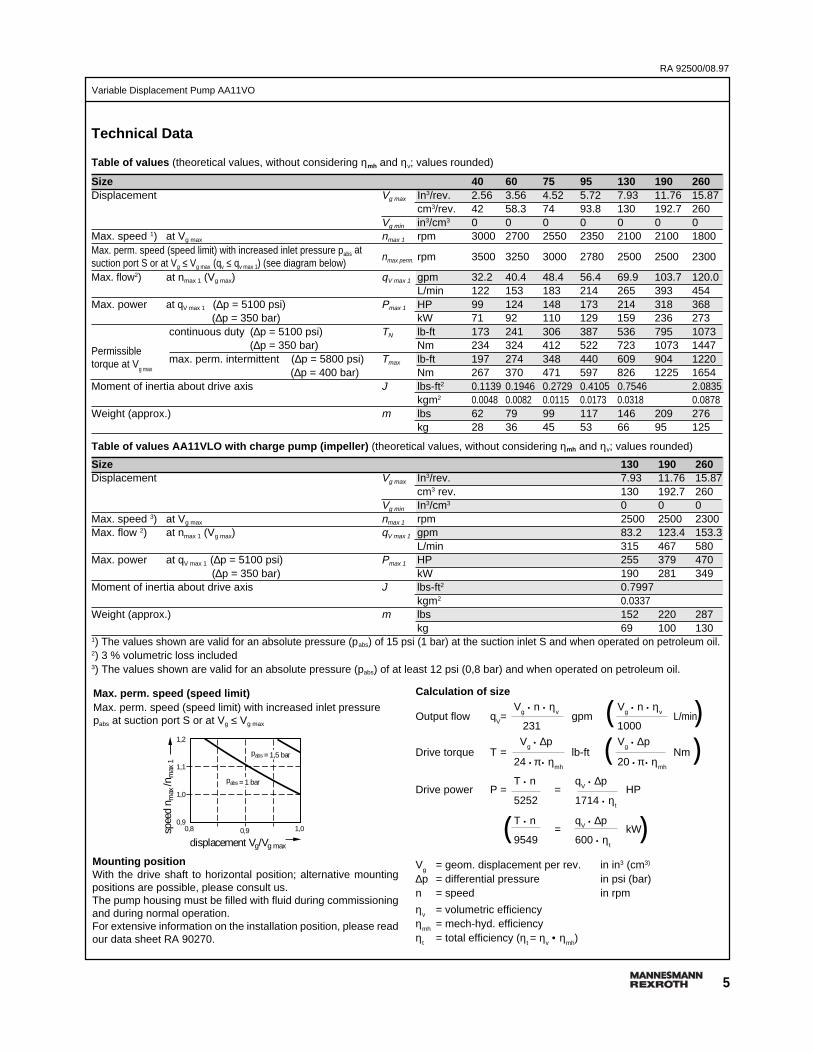
Max. perm. speed (speed limit)Max. perm. speed (speed limit) with increased inlet pressurepabs at suction port S or at Vg ≤ Vg max
Mounting positionWith the drive shaft to horizontal position; alternative mountingpositions are possible, please consult us.The pump housing must be filled with fluid during commissioningand during normal operation.For extensive information on the installation position, please readour data sheet RA 90270.
((
(
))
)
Technical Data
Table of values (theoretical values, without considering ηmh and ηv; values rounded)
Size 40 60 75 95 130 190 260Displacement Vg max In3/rev. 2.56 3.56 4.52 5.72 7.93 11.76 15.87
cm3/rev. 42 58.3 74 93.8 130 192.7 260Vg min in3/cm3 0 0 0 0 0 0 0
Max. speed 1) at Vg max nmax 1 rpm 3000 2700 2550 2350 2100 2100 1800Max. perm. speed (speed limit) with increased inlet pressure pabs atsuction port S or at Vg ≤ Vg max (qv ≤ qv max 1) (see diagram below)
nmax perm. rpm 3500 3250 3000 2780 2500 2500 2300
Max. flow2) at nmax 1 (Vg max) qV max 1 gpm 32.2 40.4 48.4 56.4 69.9 103.7 120.0L/min 122 153 183 214 265 393 454
Max. power at qV max 1 (∆p = 5100 psi) Pmax 1 HP 99 124 148 173 214 318 368
(∆p = 350 bar) kW 71 92 110 129 159 236 273 continuous duty (∆p = 5100 psi) TN lb-ft 173 241 306 387 536 795 1073
(∆p = 350 bar) Nm 234 324 412 522 723 1073 1447 max. perm. intermittent (∆p = 5800 psi) Tmax lb-ft 197 274 348 440 609 904 1220
(∆p = 400 bar) Nm 267 370 471 597 826 1225 1654Moment of inertia about drive axis J lbs-ft2 0.1139 0.1946 0.2729 0.4105 0.7546 2.0835
kgm2 0.0048 0.0082 0.0115 0.0173 0.0318 0.0878Weight (approx.) m lbs 62 79 99 117 146 209 276
kg 28 36 45 53 66 95 125
Table of values AA11VLO with charge pump (impeller) (theoretical values, without considering ηmh and ηv; values rounded)
Size 130 190 260Displacement Vg max In3/rev. 7.93 11.76 15.87
cm3 rev. 130 192.7 260Vg min In3/cm3 0 0 0
Max. speed 3) at Vg max nmax 1 rpm 2500 2500 2300Max. flow 2) at nmax 1 (Vg max) qV max 1 gpm 83.2 123.4 153.3
L/min 315 467 580Max. power at qV max 1 (∆p = 5100 psi) Pmax 1 HP 255 379 470
(∆p = 350 bar) kW 190 281 349Moment of inertia about drive axis J lbs-ft2 0.7997
kgm2 0.0337Weight (approx.) m lbs 152 220 287
kg 69 100 1301) The values shown are valid for an absolute pressure (pabs) of 15 psi (1 bar) at the suction inlet S and when operated on petroleum oil.2) 3 % volumetric loss included3) The values shown are valid for an absolute pressure (pabs) of at least 12 psi (0,8 bar) and when operated on petroleum oil.
RA 92500/08.97
6
Variable Displacement Pump AA11VO
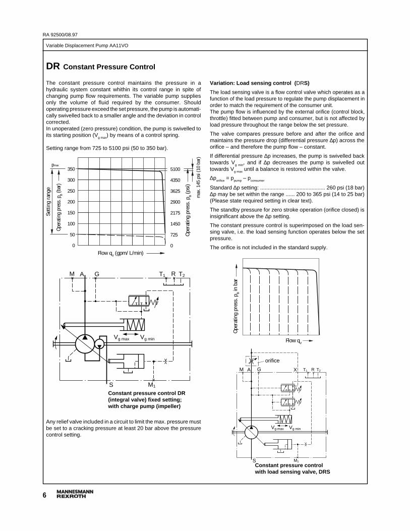
DR Constant Pressure Control
The constant pressure control maintains the pressure in ahydraulic system constant whithin its control range in spite ofchanging pump flow requirements. The variable pump suppliesonly the volume of fluid required by the consumer. Shouldoperating pressure exceed the set pressure, the pump is automati-cally swivelled back to a smaller angle and the deviation in controlcorrected.In unoperated (zero pressure) condition, the pump is swivelled toits starting position (Vg max) by means of a control spring.
Setting range from 725 to 5100 psi (50 to 350 bar).
Variation: Load sensing control ( DRS)
The load sensing valve is a flow control valve which operates as afunction of the load pressure to regulate the pump displacement inorder to match the requirement of the consumer unit.The pump flow is influenced by the external orifice (control block,throttle) fitted between pump and consumer, but is not affected byload pressure throughout the range below the set pressure.
The valve compares pressure before and after the orifice andmaintains the pressure drop (differential pressure ∆p) across theorifice – and therefore the pump flow – constant.
If differential pressure ∆p increases, the pump is swivelled backtowards Vg min, and if ∆p decreases the pump is swivelled outtowards Vg max until a balance is restored within the valve.
∆porifice
= ppump
– pconsumer
Standard ∆p setting: ........................................... 260 psi (18 bar)∆p may be set within the range ...... 200 to 365 psi (14 to 25 bar)(Please state required setting in clear text).
The standby pressure for zero stroke operation (orifice closed) isinsignificant above the ∆p setting.
The constant pressure control is superimposed on the load sen-sing valve, i.e. the load sensing function operates below the setpressure.
The orifice is not included in the standard supply.
Any relief valve included in a circuit to limit the max. pressure mustbe set to a cracking pressure at least 20 bar above the pressurecontrol setting.
Constant pressure control DR(integral valve) fixed setting;with charge pump (impeller)
T1 T2GAM R
S
Vg max Vg min
M1
Constant pressure controlwith load sensing valve, DRS
GAM X
S
Vg max Vg min
M1
T1 T2R
Setti
ng ra
nge
Flow qV (gpm/ L/min)
Flow qV
orifice
Oper
atin
g pr
ess.
pB (b
ar)
Oper
atin
g pr
ess.
pB i
n ba
r
Oper
atin
g pr
ess.
pB (
psi)
350
300
250
200
150
100
50
0
max
. 145
psi
(10
bar)
5100
4350
3625
2900
2175
1450
725
0
pmax

7
Variable Displacement Pump AA11VO
RA 92500/08.97
Variation: Remote constant pressure control ( DRG)
The remote control pressure control can be set by means of aseparately mounted pressure relief valve (1) and a lower pressurecommand value.
Setting range from ...................... 725 to 5100 psi (50 to 350 bar)
Alternatively the system can be started at low operating pressures(stand-by pressure) by actuating a 2/2 control valve (2), alsoseparately mounted.
Both functions can be carried out either singly or in combination(see circuit diagram).
The external valves are not included in delivery volume.
For a separate pressure relief valve (1) we recommend:DBDH 6 (manual actuation) see RA 25402
GAM X
S
Vg max Vg min
M1
max
. 5 m
12
T1 T2R
Variation: Pressure control for parallel operation ( DRL)
The DRL pressure control is suitable for pressure control of severalA11VO axial piston pumps working in parallel.
With an external pressure relief valve (1) the pressure commandvalue for all pumps mounted onto the system can be preset.
Setting range from ...................... 725 to 5100 psi (50 to 350 bar)
Each pump can be disconnected from the system by means of aseparately mounted 3/2 control valve (2).
Provision should be made for the check valves (3) in either thedelivery line (port A) or the pilot line (port X).
The external valves are not included in delivery volume.
For a separate pressure relief valve (1) we recommend:DBDH 6 (manual actuation) see RA 25402
GAM X
S
Vg max Vg min
M1
MA2
MD
Ms
1
2
3
3
T1 T2R
Remote constant pressure control, DRG
Pressure control for parallel operation, DRL
Setti
ng ra
nge
Flow qV (gpm / L/min)
Oper
atin
g pr
ess.
pB (b
ar)
Oper
atin
g pr
ess.
pB (
psi)
350
300
250
200
150
100
50
0
max
. 145
psi
(10
bar)
5100
4350
3625
2900
2175
1450
725
0
pmax

RA 92500/08.97
8
Variable Displacement Pump AA11VO
LR Constant Power Control
The constant power control controls the output volume of the pumpin relation to the operating pressure so that, at a constant drivespeed, the preset drive power is not exceeded.
pB • V
g = constant
Optimum power usage is obtained by accurately following thepower hyberbola.
integral pressure cut-offsetting range
Variation: Integral pressure cut-off (LRD)
The pressure cut-off is in effect a constant pressure control whichswivels the pump back to V
g min when the preset operating pressure
is reached.This function overrides the constant power control, i.e. the constantpower control is effective below the preset operating pressure.The valve is integrated into the control housing and is set in thefactory to a fixed pressure.
Setting range from 725 to 5100 psi (50 to 350 bar)
GAM
S
Vg max Vg min
M1
T1 T2R
The output power curve is influenced by the efficiency of the pump.When ordering, state in clear text:– input power P (kW)– input speed n (rpm)– max. output flow q
V max (gpm or L/min)
After all technical details have been clarified, a power diagram canbe produced by computer.
Constant power control with integralpressure cut-off (fixed setting), LRD
pB = operating pressure
Vg = displacement
Displacement
Setting rangestart of controlpsi (bar)
Displacement
Vg max Vg min
GAM
S M1
T1 T2R
Constant power control LR
Operating pressure applies a force on a piston within the controlpiston on to a rocker arm. An externally adjustable spring force isapplied to the other side of the rocker arm to determine the powersetting.Should the operating pressure exceed the set spring force, the pilotcontrol valve is operated via the rocker arm, allowing the pump toswivel towards zero output. This in turn reduces the effectivemoment on the arm of the rocker, thus allowing the operatingpressure to rise in the same ratio by which the output flow isreduced (p
B • V
g = constant).
Oper
atin
g pr
ess.
pB p
si (b
ar)
Oper
atin
g pr
ess.
pB p
si (b
ar)
Vgmin Vgmax
5100(350)
725(50)
max
min
5100 (350)
4350 (300)
3625 (250)
2900 (200)
2175 (150)
1450 (100)
725 (50)
0
4600(320)
725(50)
Vgmin Vgmax
9
Variable Displacement Pump AA11VO
RA 92500/08.97
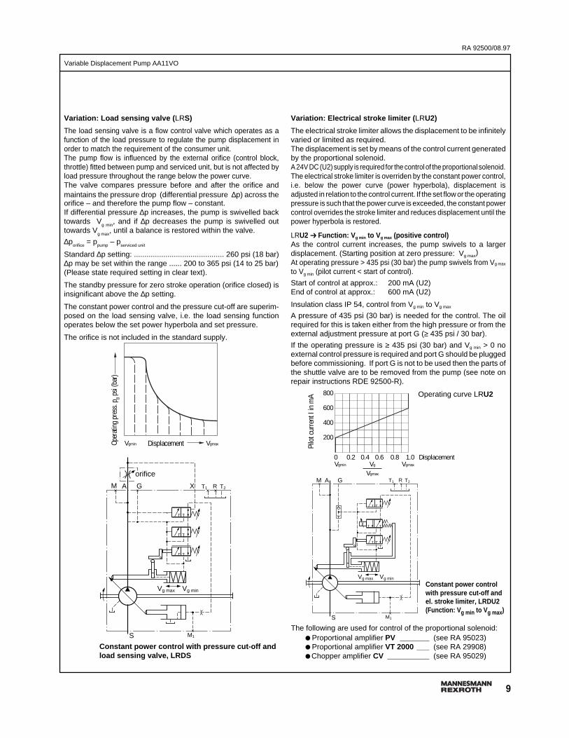
Variation: Load sensing valve ( LRS)
The load sensing valve is a flow control valve which operates as afunction of the load pressure to regulate the pump displacement inorder to match the requirement of the consumer unit.The pump flow is influenced by the external orifice (control block,throttle) fitted between pump and serviced unit, but is not affected byload pressure throughout the range below the power curve.The valve compares pressure before and after the orifice andmaintains the pressure drop (differential pressure ∆p) across theorifice – and therefore the pump flow – constant.If differential pressure ∆p increases, the pump is swivelled backtowards V
g min, and if ∆p decreases the pump is swivelled out
towards Vg max
, until a balance is restored within the valve.
∆porifice
= ppump
– pserviced unit
Standard ∆p setting: ........................................... 260 psi (18 bar)∆p may be set within the range ...... 200 to 365 psi (14 to 25 bar)(Please state required setting in clear text).
The standby pressure for zero stroke operation (orifice closed) isinsignificant above the ∆p setting.
The constant power control and the pressure cut-off are superim-posed on the load sensing valve, i.e. the load sensing functionoperates below the set power hyperbola and set pressure.
The orifice is not included in the standard supply.
Variation: Electrical stroke limiter ( LRU2)
The electrical stroke limiter allows the displacement to be infinitelyvaried or limited as required.The displacement is set by means of the control current generatedby the proportional solenoid.A 24V DC (U2) supply is required for the control of the proportional solenoid.The electrical stroke limiter is overriden by the constant power control,i.e. below the power curve (power hyperbola), displacement isadjusted in relation to the control current. If the set flow or the operatingpressure is such that the power curve is exceeded, the constant powercontrol overrides the stroke limiter and reduces displacement until thepower hyperbola is restored.
LRU2 ➔ Function: V g min to V g max (positive control)As the control current increases, the pump swivels to a largerdisplacement. (Starting position at zero pressure: Vg max)At operating pressure > 435 psi (30 bar) the pump swivels from Vg max
to Vg min (pilot current < start of control).
Start of control at approx.: 200 mA (U2)End of control at approx.: 600 mA (U2)
Insulation class IP 54, control from Vg min to Vg max
A pressure of 435 psi (30 bar) is needed for the control. The oilrequired for this is taken either from the high pressure or from theexternal adjustment pressure at port G (≥ 435 psi / 30 bar).
If the operating pressure is ≥ 435 psi (30 bar) and Vg min > 0 noexternal control pressure is required and port G should be pluggedbefore commissioning. If port G is not to be used then the parts ofthe shuttle valve are to be removed from the pump (see note onrepair instructions RDE 92500-R).
The following are used for control of the proportional solenoid:● Proportional amplifier PV _______ (see RA 95023)● Proportional amplifier VT 2000 ___ (see RA 29908)● Chopper amplifier CV __________ (see RA 95029)
Operating curve LRU2
GAM
Vg max Vg min
S M1
T1 T2RGAM X
S
Vg max Vg min
M1
T1 T2R
orifice
Constant power control with pressure cut-off andload sensing valve, LRDS
Constant power controlwith pressure cut-off andel. stroke limiter, LRDU2(Function: V g min to Vg max )
Pilo
t cur
rent
I in
mA
0 0.2 0.4 0.6 0.8 1.0Vgmin Vg Vgmax
Vgmax
800
600
400
200
Displacement
DisplacementOper
ating
pre
ss. p
B psi
(bar
)
Vgmin Vgmax
RA 92500/08.97
10
Variable Displacement Pump AA11VO
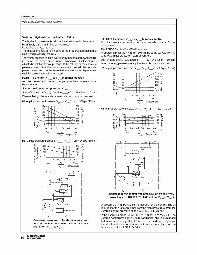
Variation: Hydraulic stroke limiter ( LRH...)
The hydraulic stroke limiter allows the maximum displacement tobe infinitely varied or limited as required.Control range Vg max to Vg min .The displacement is set by means of the pilot pressure applied atport Y (max 580 psi / 40 bar).
The hydraulic stroke limiter is overriden by the constant power control,i.e. below the power curve (power hyperbola), displacement isadjusted in relation to pilot pressure. If the set flow or the operatingpressure is such that the power curve is exceeded, the constantpower control overrides the stroke limiter and reduces displacementuntil the power hyperbola is restored.
H1/H5 ➔ Function: V g max to V g min (negative control)As pilot pressure increases the pump swivels towards lowerdisplacement.
Starting position at zero pressure: Vg max
Start of control, (at Vg max), settable ____60 - 145 psi (4 – 10 bar)
When ordering, please state required start of control in clear text.
H1 ➔ pilot pressure increase (Vg max
– Vg min
)__∆p = 365 psi (25 bar)
H2 / H6 ➔ Function: V g min to Vg max (positive control)As pilot pressure increases the pump swivels towards higherdisplacement.Starting position at zero pressure: Vg max
At operating pressure > 435 psi (30 bar) the pump swivels from Vg
max to Vg min (pilot pressure < start of control).
Start of control (at Vg min), settable _____60 - 145 psi (4 – 10 bar)When ordering, please state required start of control in clear text.
H2 ➔ pilot pressure increase (Vg min – Vg max)___ ∆p = 365 psi (25 bar)
Constant power control with pressure cut-offand hydraulic stroke limiter, LRDH1, LRDH5(Function: V g max to Vg min )
GAM Y
Vg max Vg min
S M1
T1 T2R
H6 ➔ pilot pressure increase (Vg min – Vg max)____ ∆p = 10 bar
GAM Y
Vg max Vg min
S M1
T1 T2R
Constant power control with pressure cut-off and hydr.stroke limiter , LRDH2, LRDH6 (Function: V g min to V g max)
A pressure of 435 psi (30 bar) is needed for the control. The oilrequired for this is taken either from the high pressure or from theexternal control pressure at port G (≥ 435 PSI / 30 bar).
If the operating pressure is ≥ 435 psi (30 bar) and Vg min > 0 noexternal control pressure is required and port G should be pluggedbefore commissioning. If port G is not to be used then the parts ofthe shuttle valve are to be removed from the pump (see note onrepair instructions RDE 92500-R).
H5 ➔ pilot pressure increase (Vg max
– Vg min
)__∆p = 145 psi (10 bar)
Pilo
t pre
ss. p
St (b
ar)
Setti
ng ra
nge
Displacement
0 0.2 0.4 0.6 0.8 1.0Vgmin Vg Vgmax
Vgmax
201510
4
Pilo
t pre
ss. p
St (p
si)290
220145
60
Displacement
Pilo
t pre
ss. p
St (b
ar)
Setti
ng ra
nge
0 0.2 0.4 0.6 0.8 1.0Vgmin Vg Vgmax
Vgmax
353025201510
4 Pilo
t pre
ss. p
St (p
si)510
435365290220145
60
Pilo
t pre
ss. p
St (b
ar)
Setti
ng ra
nge
Pilo
t pre
ss. p
St (p
si)
Pilo
t pre
ss. p
St (p
si)
Displacement
0 0.2 0.4 0.6 0.8 1.0Vgmin Vg Vgmax
Vgmax
201510
4
290220145
60
Displacement
Pilo
t pre
ss. p
St (b
ar)
Se
tting
rang
e
0 0.2 0.4 0.6 0.8 1.0Vgmin Vg Vgmax
Vgmax
353025201510
4
510435365290220145
60
11
Variable Displacement Pump AA11VO
RA 92500/08.97
GAM
S
Vg max Vg min
Z
M1
LR
pHD
T1 T2R
GAM
S
Vg max Vg min
Z
M1
pHD
T1 T2R
GAM
S
Vg max Vg min
Z
M1
T1 T2R
GAM
S
Vg max Vg min
Z
M1
T1 T2R
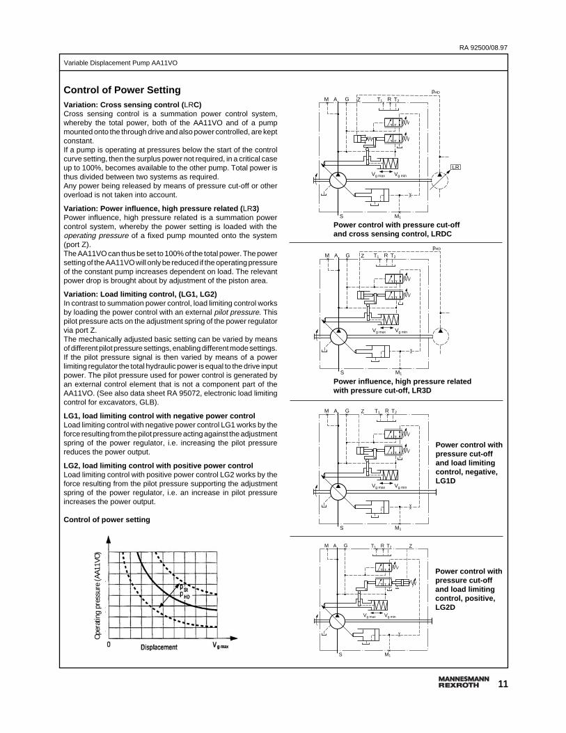
Power control with pressure cut-offand cross sensing control, LRDC
Power influence, high pressure relatedwith pressure cut-off, LR3D
Control of Power SettingVariation: Cross sensing control ( LRC)Cross sensing control is a summation power control system,whereby the total power, both of the AA11VO and of a pumpmounted onto the through drive and also power controlled, are keptconstant.If a pump is operating at pressures below the start of the controlcurve setting, then the surplus power not required, in a critical caseup to 100%, becomes available to the other pump. Total power isthus divided between two systems as required.Any power being released by means of pressure cut-off or otheroverload is not taken into account.
Variation: Power influence, high pressure related ( LR3)Power influence, high pressure related is a summation powercontrol system, whereby the power setting is loaded with theoperating pressure of a fixed pump mounted onto the system(port Z).The AA11VO can thus be set to 100% of the total power. The powersetting of the AA11VO will only be reduced if the operating pressureof the constant pump increases dependent on load. The relevantpower drop is brought about by adjustment of the piston area.
Variation: Load limiting control, (LG1, LG2)In contrast to summation power control, load limiting control worksby loading the power control with an external pilot pressure. Thispilot pressure acts on the adjustment spring of the power regulatorvia port Z.The mechanically adjusted basic setting can be varied by meansof different pilot pressure settings, enabling different mode settings.If the pilot pressure signal is then varied by means of a powerlimiting regulator the total hydraulic power is equal to the drive inputpower. The pilot pressure used for power control is generated byan external control element that is not a component part of theAA11VO. (See also data sheet RA 95072, electronic load limitingcontrol for excavators, GLB).
LG1, load limiting control with negative power controlLoad limiting control with negative power control LG1 works by theforce resulting from the pilot pressure acting against the adjustmentspring of the power regulator, i.e. increasing the pilot pressurereduces the power output.
LG2, load limiting control with positive power controlLoad limiting control with positive power control LG2 works by theforce resulting from the pilot pressure supporting the adjustmentspring of the power regulator, i.e. an increase in pilot pressureincreases the power output.
Control of power setting
Power control withpressure cut-offand load limitingcontrol, negative,LG1D
Power control withpressure cut-offand load limitingcontrol, positive,LG2D
Oper
atin
g pr
essu
re (A
A11V
O)
RA 92500/08.97
12
Variable Displacement Pump AA11VO
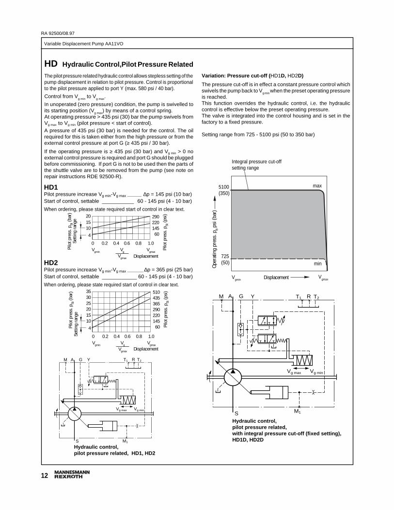
HD Hydraulic Control,Pilot Pressure Related
The pilot pressure related hydraulic control allows stepless setting of thepump displacement in relation to pilot pressure. Control is proportionalto the pilot pressure applied to port Y (max. 580 psi / 40 bar).
Control from Vg min
to Vg max
.
In unoperated (zero pressure) condition, the pump is swivelled toits starting position (Vg max) by means of a control spring.At operating pressure > 435 psi (30) bar the pump swivels fromVg max to Vg min (pilot pressure < start of control).A pressure of 435 psi (30 bar) is needed for the control. The oilrequired for this is taken either from the high pressure or from theexternal control pressure at port G (≥ 435 psi / 30 bar).
If the operating pressure is ≥ 435 psi (30 bar) and Vg min > 0 noexternal control pressure is required and port G should be pluggedbefore commissioning. If port G is not to be used then the parts ofthe shuttle valve are to be removed from the pump (see note onrepair instructions RDE 92500-R).
Variation: Pressure cut-off (HD1D, HD2D)
The pressure cut-off is in effect a constant pressure control whichswivels the pump back to Vg min when the preset operating pressureis reached.This function overrides the hydraulic control, i.e. the hydrauliccontrol is effective below the preset operating pressure.The valve is integrated into the control housing and is set in thefactory to a fixed pressure.
Setting range from 725 - 5100 psi (50 to 350 bar)
Hydraulic control,pilot pressure related, HD1, HD2
HD1Pilot pressure increase Vg min-Vg max _______ ∆p = 145 psi (10 bar)Start of control, settable ___________ 60 - 145 psi (4 - 10 bar)
When ordering, please state required start of control in clear text.
GAM
S
Vg max Vg min
Y
M1
T1 T2R
HD2Pilot pressure increase Vg min-Vg max ________ ∆p = 365 psi (25 bar)Start of control, settable ____________ 60 - 145 psi (4 - 10 bar)
When ordering, please state required start of control in clear text.
Displacement
Hydraulic control,pilot pressure related,with integral pressure cut-off (fixed setting),HD1D, HD2D
GAM Y
S
Vg max Vg min
M1
T1 T2R
Pilo
t pre
ss. p
St (b
ar)
Setti
ng ra
nge
Pilo
t pre
ss. p
St (b
ar)
Setti
ng ra
nge
Displacement
Integral pressure cut-offsetting range
Displacement
Oper
atin
g pr
ess.
pB p
si (b
ar)
max5100(350)
min725(50)
VgmaxVgmin
0 0.2 0.4 0.6 0.8 1.0Vgmin Vg Vgmax
Vgmax
201510
4
Pilo
t pre
ss. p
St (p
si)290
220145
60
0 0.2 0.4 0.6 0.8 1.0Vgmin Vg Vgmax
Vgmax
353025201510
4 Pilo
t pre
ss. p
St (p
si)510
435365290220145
60
13
Variable Displacement Pump AA11VO
RA 92500/08.97
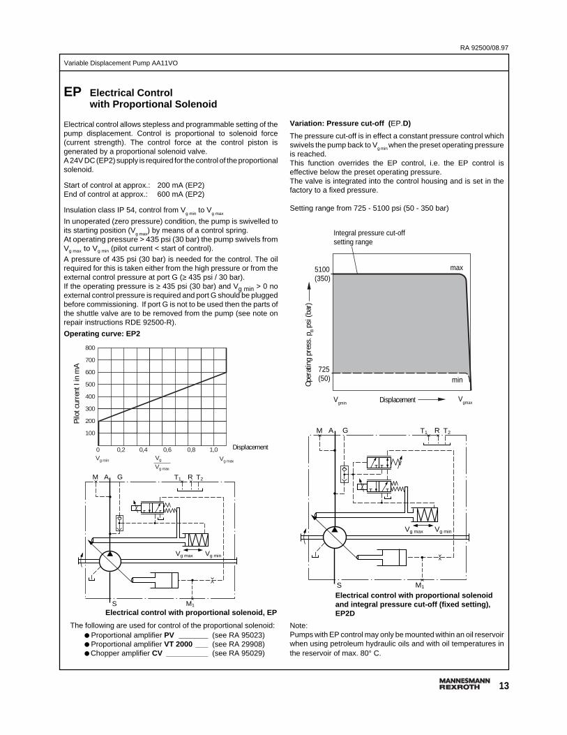
Variation: Pressure cut-off (EP.D)
The pressure cut-off is in effect a constant pressure control whichswivels the pump back to Vg min when the preset operating pressureis reached.This function overrides the EP control, i.e. the EP control iseffective below the preset operating pressure.The valve is integrated into the control housing and is set in thefactory to a fixed pressure.
Setting range from 725 - 5100 psi (50 - 350 bar)
GAM
S
Vg max Vg min
M1
T1 T2R
Electrical control with proportional solenoidand integral pressure cut-off (fixed setting) ,EP2D
Note:Pumps with EP control may only be mounted within an oil reservoirwhen using petroleum hydraulic oils and with oil temperatures inthe reservoir of max. 80° C.
Displacement
The following are used for control of the proportional solenoid:● Proportional amplifier PV _______ (see RA 95023)● Proportional amplifier VT 2000 ___ (see RA 29908)● Chopper amplifier CV __________ (see RA 95029)
GAM
S
Vg max Vg min
M1
T1 T2R
Pilo
t cur
rent
I in
mA
Electrical control with proportional solenoid, EP
EP Electrical Controlwith Proportional Solenoid
Electrical control allows stepless and programmable setting of thepump displacement. Control is proportional to solenoid force(current strength). The control force at the control piston isgenerated by a proportional solenoid valve.A 24V DC (EP2) supply is required for the control of the proportionalsolenoid.
Start of control at approx.: 200 mA (EP2)End of control at approx.: 600 mA (EP2)
Insulation class IP 54, control from Vg min
to Vg max
In unoperated (zero pressure) condition, the pump is swivelled toits starting position (V
g max) by means of a control spring.
At operating pressure > 435 psi (30 bar) the pump swivels fromVg max to Vg min (pilot current < start of control).A pressure of 435 psi (30 bar) is needed for the control. The oilrequired for this is taken either from the high pressure or from theexternal control pressure at port G (≥ 435 psi / 30 bar).If the operating pressure is ≥ 435 psi (30 bar) and Vg min > 0 noexternal control pressure is required and port G should be pluggedbefore commissioning. If port G is not to be used then the parts ofthe shuttle valve are to be removed from the pump (see note onrepair instructions RDE 92500-R).
Operating curve: EP2
Integral pressure cut-offsetting range
Displacement
Oper
atin
g pr
ess.
pB p
si (b
ar)
max5100(350)
min725(50)
VgmaxVgmin
800
700
600
500
400
300
200
100
0 0,2 0,4 0,6 0,8 1,0Vg min Vg
Vg max
Vg max
RA 92500/08.97
14
Variable Displacement Pump AA11VOBefore finalising your design, please request a certified drawing.
Dimensions in inches and millimeters ().
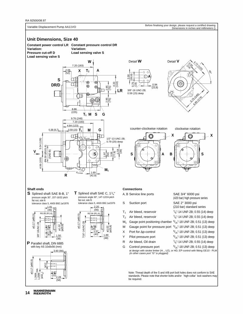
T Splined shaft SAE C, 11/4"pressure angle 30°, 14T-12/24 pitchflat root, side fittolerance class 5, ANSI B92.1a/1976
Constant pressure control DRVariation:Load sensing valve S
Unit Dimensions, Size 40Constant power control LRVariation:Pressure cut-off DLoad sensing valve S
Connections
A, B Service line ports SAE 3/4" 6000 psi(420 bar) high pressure series
S Suction port SAE 2" 3000 psi(210 bar) standard series
T1 Air bleed, reservoir 7/8"-14 UNF-2B; 0.55 (14) deep
T2 Air bleed, reservoir 7/8"-14 UNF-2B; 0.55 (14) deep
M1 Gauge point positioning chamber 9/16"-18 UNF-2B; 0.51 (13) deep
M Gauge point for pressure port 9/16"-18 UNF-2B; 0.51 (13) deep
X Port for ∆p-control 9/16"-18 UNF-2B; 0.51 (13) deep
Y Pilot pressure port 9/16"-18 UNF-2B; 0.51 (13) deep
R Air bleed, Oil drain 7/8"-14 UNF-2B; 0.55 (14) deep
G Control pressure port 9/16"-18 UNF-2B; 0.51 (13) deepat design with stroke limiter (H.., U2), or HD, EP-control with fitting GE10 - PLM(in other cases port "G" is plugged)
P Parallel shaft, DIN 6885with key AS 10x8x56 (mm)
Shaft endsS Splined shaft SAE B-B, 1"
pressure angle 30°, 15T-16/32 pitchflat root, side fittolerance class 5, ANSI B92.1a/1976
LR
SDR/D
Detail W
3/8"-16 UNC-2B;0.59 (15) deep
counter-clockwise rotation
0.94(23,8)
clockwise rotation
1.69(42,9)
8.86(225)
X
AS
X
SB
Detail V
2.00
(50,
8)0.
75(1
9)
A
5.75
(146
)
6.85
(174
)
4.72 (120)
0.55(14)
Vg min
45°
T1
9.76 (248)7.20 (183)
M S G
4.84 (123)
0.59 (15)0.38 (9,7)
Vg max
T1 M G
1/2"-13 UNC-2B;0.79 (20) deep
2.05(52)
7.20 (183)
T2X A
W
2.95
(75)
2.95
(75) 4.
33(1
10)
RM1
S
5.04
(12
8)4.
06 (
103)
Ø4.
00 (
Ø10
1,6)
(SA
E-B
)
V
3.06
(77,
8)
1.97
(50) 1.
54(3
9)
Note: Thread depth of the S and A/B port bolt holes does not conform to SAEstandards. Please note that shorter bolts and/or `high-collar´ lock washers maybe required.
1.81(46)
0.87(22)1.18(30) 1.50
(38)
ø1.
02(ø
20,8
)
ø3.
17 (
ø80
,5)
3/8"
-16U
NC
-2B
3.60 (66)
0.87(22)
M12
ø3.
17 (
ø80
,5)
1.26
061.
2599
2.28(58)
(ø32
k6)D
IA
2.20(56)
1.10(28)
1.57(40) 1.89
(48)
ø1.
02(ø
25,8
)
ø3.
17 (
ø80
,5)
7/16
"-14
UN
C-2
B
R0.06 (R1,6) R0.06 (R1,6)

15
Variable Displacement Pump AA11VO
RA 92500/08.97
Before finalising your design, please request a certified drawing.Dimensions in inches and millimeters ().
Unit Dimensions, Size 40Constant power control with hydraulic stroke limiter andpressure cut-off LRDH1/LRDH5 (function: V g max to Vg min )
Constant power control with hydraulic stroke limiter andpressure cut-off LRDH2/LRDH6 (function: V g min to Vg max)
Electrical control with proportional solenoid,pressure cut-off EP.D (in preparation)
Hydraulic control, pilot pressure related,Pressure cut-off HD1D, HD2D
DH1/5 LR
9.76 (248)
6.02
(15
3)
T1
R
S
G
MY G
M1
SMT1
AT2Y
DH2/6 LR
9.76 (248)
6.02
(15
3)
T1
R
S
G
MY G
M1
SMT1
AT2Y
0.73(18.5)
8.19 (208)
5.16
(13
1)
T1
R
S
G
MY G
M1
SMT1
AT2Y
0.89(22.5)
DHD1/2
RA 92500/08.97
16
Variable Displacement Pump AA11VOBefore finalising your design, please request a certified drawing.
Dimensions in inches and millimeters ().
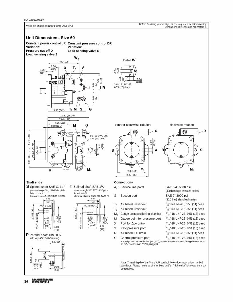
Shaft endsS Splined shaft SAE C, 11/4"
pressure angle 30°, 14T-12/24 pitchflat root, side fittolerance class 5, ANSI B92.1a/1976
P Parallel shaft, DIN 6885with key AS 10x8x56 (mm)
T Splined shaft SAE 13/8"pressure angle 30°, 21T-16/32 pitchflat root, side fittolerance class 5, ANSI B92.1a/1976
Unit Dimensions, Size 60Constant power control LRVariation:Pressure cut-off DLoad sensing valve S
Constant pressure control DRVariation:Load sensing valve S
Connections
A, B Service line ports SAE 3/4" 6000 psi(420 bar) high pressure series
S Suction port SAE 2" 3000 psi(210 bar) standard series
T1 Air bleed, reservoir 7/8"-14 UNF-2B; 0.55 (14) deep
T2 Air bleed, reservoir 7/8"-14 UNF-2B; 0.55 (14) deep
M1 Gauge point positioning chamber 9/16"-18 UNF-2B; 0.51 (13) deep
M Gauge point for pressure port 9/16"-18 UNF-2B; 0.51 (13) deep
X Port for ∆p-control 9/16"-18 UNF-2B; 0.51 (13) deep
Y Pilot pressure port 9/16"-18 UNF-2B; 0.51 (13) deep
R Air bleed, Oil drain 7/8"-14 UNF-2B; 0.55 (14) deep
G Control pressure port 9/16"-18 UNF-2B; 0.51 (13) deepat design with stroke limiter (H.., U2), or HD, EP-control with fitting GE10 - PLM(in other cases port "G" is plugged)
LR
Detail W
3/8"-16 UNC-2B;0.79 (20) deep
counter-clockwise rotation
0.94(23,8)
clockwise rotation
1.69(42,9)
X
AS
X
SB
2.00
(50,
8)0.
75(1
9)
A
Vg min
T19.53 (242)
10.30 (261,5)
M S G
7.80 (198)5.35 (136)
0.50 (12,7)
Vg max
T1
M G
1/2"-13 UNC-2B;0.79 (20) deep
2.58(65,5)
7.80 (198)
T2X A
W
3.23
(82)
3.23
(82)
4.41
(112
)
R M1
S
5.35
(13
6)4.
37 (
111)
Ø5.
00 (
Ø12
7)
(SA
E-C
)
3.06
(77,
8)
1.97
(50)
1.81
(46)
0.75(19)
SDR/D
M1 M17.13 (181)
8.39 (213)
0.69
(17,
5)
Note: Thread depth of the S and A/B port bolt holes does not conform to SAEstandards. Please note that shorter bolts and/or `high-collar´ lock washers maybe required.
2.20(56)
1.10(28)1.57(40) 1.89
(48)
ø1.
02(ø
25,8
)
ø3.
58 (
ø91
)
7/16
"-14
UN
C-2
B
3.60 (66)
1.10(28)
M12
ø3.
58 (
ø91
)
1.37
871.
3780
2.28(58)
(ø35
k6)D
IA
2.20(56)
1.10(28)
1.57(40) 1.89
(48)
ø1.
19(ø
30,2
)
ø3.
58 (
ø91
)
7/16
"-14
UN
C-2
B
R0.06 (R1,6) R0.06 (R1,6)
17
Variable Displacement Pump AA11VO
RA 92500/08.97
Before finalising your design, please request a certified drawing.Dimensions in inches and millimeters ().
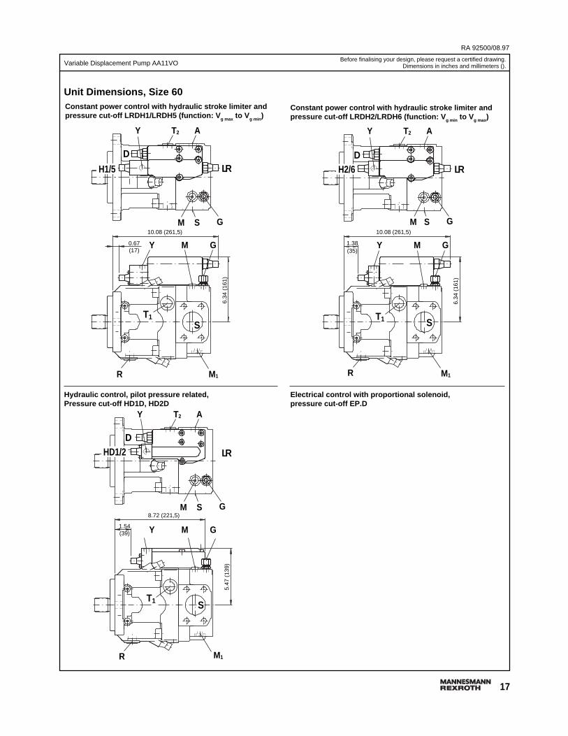
Constant power control with hydraulic stroke limiter andpressure cut-off LRDH1/LRDH5 (function: V g max to V g min )
Constant power control with hydraulic stroke limiter andpressure cut-off LRDH2/LRDH6 (function: V g min to Vg max)
Electrical control with proportional solenoid,pressure cut-off EP.D
Hydraulic control, pilot pressure related,Pressure cut-off HD1D, HD2D
Unit Dimensions, Size 60
D
H1/5
10.08 (261,5)6.
34 (
161)
T1
R
S
G
MY G
M1
SM
AT2Y
LR
0.67(17)
DH2/6
10.08 (261,5)
6.34
(16
1)
T1
R
S
MY G
M1
AT2Y
LR
1.38(35)
GSM
D
8.72 (221,5)
5.47
(13
9)
T1
R
S
G
MY G
M1
SM
AT2Y
LR
1.54(39)
HD1/2

RA 92500/08.97
18
Variable Displacement Pump AA11VOBefore finalising your design, please request a certified drawing.
Dimensions in inches and millimeters ().
Shaft endsS Splined shaft SAE C, 11/4"
pressure angle 30°, 14T-12/24 pitchflat root, side fittolerance class 5, ANSI B92.1a/1976
P Parallel shaft, DIN 6885with key AS 12x8x80 (mm)
T Splined shaft SAE 13/8"pressure angle 30°, 21T-16/32 pitchflat root, side fittolerance class 5, ANSI B92.1a/1976
Unit Dimensions, Size 75Constant power control LRVariation:Pressure cut-off DLoad sensing valve S
Constant pressure control DRVariation:Load sensing valve S
Connections
A, B Service line ports SAE 1" 6000 psi(420 bar) high pressure series
S Suction port SAE 2 1/2" 2500 psi(170 bar) standard series
T1 Air bleed, reservoir 7/8"-14 UNF-2B; 0.55 (14) deep
T2 Air bleed, reservoir 7/8"-14 UNF-2B; 0.55 (14) deep
M1 Gauge point positioning chamber 9/16"-18 UNF-2B; 0.51 (13) deep
M Gauge point for pressure port 9/16"-18 UNF-2B; 0.51 (13) deep
X Port for ∆p-control 9/16"-18 UNF-2B; 0.51 (13) deep
Y Pilot pressure port 9/16"-18 UNF-2B; 0.51 (13) deep
R Air bleed, Oil drain 7/8"-14 UNF-2B; 0.55 (14) deep
G Control pressure port 9/16"-18 UNF-2B; 0.51 (13) deepat design with stroke limiter (H.., U2), or HD, EP-control with fitting GE10 - PLM(in other cases port "G" is plugged)
LR
SDR/D
Detail W
7/16"-14 UNC-2B;0.87 (22) deep
counter-clockwise rotation
1.09(27,8)
clockwise rotation
2.00(50,8)
10.24 (260)
X
AS
X
SB
2.25
(57,
2)0.
98(2
5)
A
Vg min
T1
10.85 (275,5)8.46 (215)
M S G
5.83 (148)0.50 (12,7)
Vg max
T1 M G
1/2"-13 UNC-2B;0.75 (19) deep
3.15(80)
8.46 (215)
T2X A
W
3.48
(88,
5)3.
48(8
8,5)
4.47
(11
3,5)
RM1
S
5.61
(14
2,5)
4.61
(11
7)
Ø6.
00 (
Ø15
2,4)
(SA
E-D
)
3.50
(88,
9)
2.48
(63) 1.
97(5
0)
0.75 (19)
ø0.8
3(ø
21)
M1 M16.36 (161,6)
7.87 (200)
6.36
(16
1,6)
Note: Thread depth of the S and A/B port bolt holes does not conform to SAEstandards. Please note that shorter bolts and/or `high-collar´ lock washers maybe required.
2.20(56)
1.10(28)1.57(40) 1.89
(48)
ø1.
02(ø
25,8
)
ø3.
78 (
ø96
)
7/16
"-14
UN
C-2
B
3.62 (92)
1.42(36)
M16
ø3.
78 (
ø96
)
1.57
551.
5749
3.23(82)
(ø40
k6)D
IA
2.20(56)
1.10(28)
1.57(40) 1.89
(48)
ø1.
19(ø
30,2
)
ø3.
78 (
ø96
)
7/16
"-14
UN
C-2
B
R0.06 (R1,6) R0.06 (R1,6)
19
Variable Displacement Pump AA11VO
RA 92500/08.97
Before finalising your design, please request a certified drawing.Dimensions in inches and millimeters ().
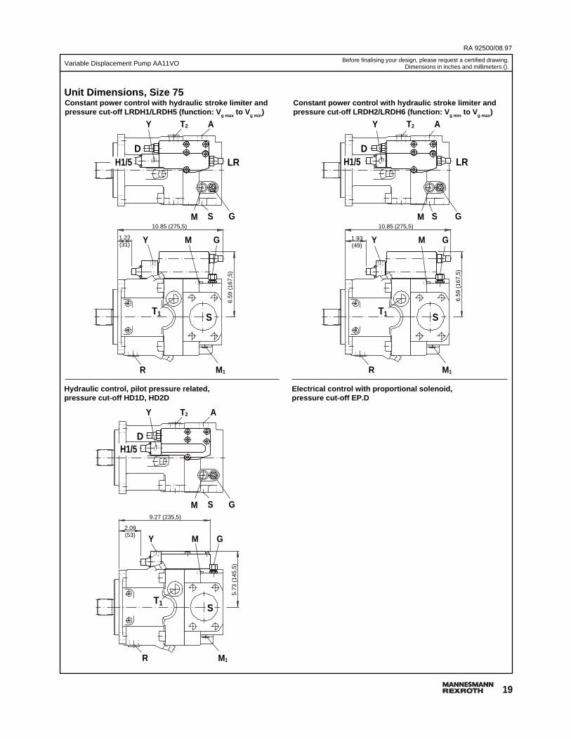
Constant power control with hydraulic stroke limiter andpressure cut-off LRDH1/LRDH5 (function: V g max to Vg min )
Constant power control with hydraulic stroke limiter andpressure cut-off LRDH2/LRDH6 (function: V g min to Vg max )
Electrical control with proportional solenoid,pressure cut-off EP.D
Hydraulic control, pilot pressure related,pressure cut-off HD1D, HD2D
Unit Dimensions, Size 75
DH1/5
10.85 (275,5)6.
59 (
167,
5)
T1
R
S
G
MY G
M1
SM
AT2Y
LR
1.22(31)
DH1/5
10.85 (275,5)
6.59
(16
7,5)
T1
R
S
G
MY G
M1
SM
LR
1.93(49)
AT2Y
DH1/5
9.27 (235,5)
5.73
(14
5,5)
T1
R
S
G
MY G
M1
SM
AT2Y
2.09(53)
RA 92500/08.97
20
Variable Displacement Pump AA11VOBefore finalising your design, please request a certified drawing.
Dimensions in inches and millimeters ().
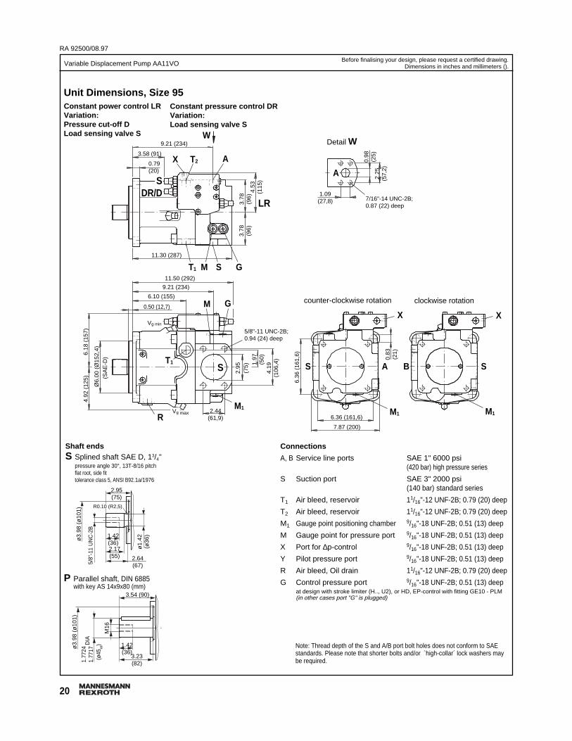
Unit Dimensions, Size 95Constant power control LRVariation:Pressure cut-off DLoad sensing valve S
Shaft endsS Splined shaft SAE D, 13/4"
pressure angle 30°, 13T-8/16 pitchflat root, side fittolerance class 5, ANSI B92.1a/1976
P Parallel shaft, DIN 6885with key AS 14x9x80 (mm)
Constant pressure control DRVariation:Load sensing valve S
Connections
A, B Service line ports SAE 1" 6000 psi(420 bar) high pressure series
S Suction port SAE 3" 2000 psi(140 bar) standard series
T1 Air bleed, reservoir 11/16"-12 UNF-2B; 0.79 (20) deep
T2 Air bleed, reservoir 11/16"-12 UNF-2B; 0.79 (20) deep
M1 Gauge point positioning chamber 9/16"-18 UNF-2B; 0.51 (13) deep
M Gauge point for pressure port 9/16"-18 UNF-2B; 0.51 (13) deep
X Port for ∆p-control 9/16"-18 UNF-2B; 0.51 (13) deep
Y Pilot pressure port 9/16"-18 UNF-2B; 0.51 (13) deep
R Air bleed, Oil drain 11/16"-12 UNF-2B; 0.79 (20) deep
G Control pressure port 9/16"-18 UNF-2B; 0.51 (13) deepat design with stroke limiter (H.., U2), or HD, EP-control with fitting GE10 - PLM(in other cases port "G" is plugged)
LR
SDR/D
Detail W
7/16"-14 UNC-2B;0.87 (22) deep
counter-clockwise rotation
1.09(27,8)
clockwise rotation
2.44(61,9)
11.30 (287)
X
AS
X
SB2.
25(5
7,2)
0.98
(25)
A
Vg min
T1
11.50 (292)
9.21 (234)
M S G
6.10 (155)
0.50 (12,7)
Vg max
T1
M G
5/8"-11 UNC-2B;0.94 (24) deep
0.79(20)
9.21 (234)
T2X A
W
3.78
(96)
3.78
(96)
4.53
(115
)
RM1
S
4.92
(12
5)
Ø6.
00 (
Ø15
2,4)
(SA
E-D
)
1.97
(50)
2.95
(75)
4.19
(106
,4)
3.58 (91)
M1 M1
6.36
(16
1,6)
0.83
(21)
6.36 (161,6)
7.87 (200)
6.18
(15
7)
Note: Thread depth of the S and A/B port bolt holes does not conform to SAEstandards. Please note that shorter bolts and/or `high-collar´ lock washers maybe required.
2.95(75)
1.42(36)2.17(55) 2.64
(67)
ø1.
42(ø
36)
ø3.
98 (
ø10
1)
5/8"
-11
UN
C-2
B
3.54 (90)
1.42(36)
M16
ø3.
98 (
ø10
1)
1.77
241.
7717
3.23(82)
(ø45
k6)D
IA
R0.10 (R2,5)

21
Variable Displacement Pump AA11VO
RA 92500/08.97
Before finalising your design, please request a certified drawing.Dimensions in inches and millimeters ().
Constant power control with hydraulic stroke limiter andpressure cut-off LRDH1/LRDH5 (function: V g max to V g min )
Constant power control with hydraulic stroke limiter andpressure cut-off LRDH2/LRDH6 (function: V g min to Vg max )
Electrical control with proportional solenoid,pressure cut-off EP.D
Hydraulic control, pilot pressure related,pressure cut-off HD1D, HD2D
Unit Dimensions, Size 95
DH1/5
11.50 (292)7.
09 (
180)
T1
R
S
G
MY G
M1
SM
AT2Y
LR
1.54(39)
DLR
11.50 (292)
7.09
(18
0)
T1
R
S
G
MY G
M1
SM
AT2Y
2.28(58)
H2/6
9.92 (252)
6.10
(15
5)
T1
R
S
G
MY G
M1
SM
AT2Y
2.42(61,5)
DHD1/2

RA 92500/08.97
22
Variable Displacement Pump AA11VOBefore finalising your design, please request a certified drawing.
Dimensions in inches and millimeters ().
Shaft endsS Splined shaft SAE D, 13/4"
pressure angle 30°, 13T-8/16 pitchflat root, side fittolerance class 5, ANSI B92.1a/1976
P Parallel shaft, DIN 6885with key AS 14x9x80 (mm)
Connections
A, B Service line ports (without charge pump)SAE 1" 6000 psi(420 bar) high pressure series
A, B Service line ports (with charge pump)SAE 1 1/4" 6000 psi(420 bar) high pressure series
S Suction port SAE 3" 2000 psi(140 bar) standard series
T1 Air bleed, reservoir 11/16"-12 UNF-2B; 0.79 (20) deep
T2 Air bleed, reservoir 15/16"-12 UNF-2B; 0.79 (20) deep
M1 Gauge point positioning chamber 9/16"-18 UNF-2B; 0.51 (13) deep
M Gauge point for pressure port 9/16"-18 UNF-2B; 0.51 (13) deep
X Port for ∆p-control 9/16"-18 UNF-2B; 0.51 (13) deep
Y Pilot pressure port 9/16"-18 UNF-2B; 0.51 (13) deep
R Air bleed, Oil drain 15/16"-12 UNF-2B; 0.79 (20) deep
G Control pressure port 9/16"-18 UNF-2B; 0.51 (13) deepat design with stroke limiter (H.., U2), or HD, EP-control with fitting GE10 - PLM(in other cases port "G" is plugged)
Unit Dimensions, Size 130Constant power control LRVariation:Pressure cut-off DLoad sensing valve S
Constant pressure control DRVariation:Load sensing valve S
X
8.03
Note: Thread depth of the S and A/B port bolt holes does not conform to SAEstandards. Please note that shorter bolts and/or `high-collar´ lock washers maybe required.
LR
SDR/D
Detail W
7/16"-14 UNC-2B;0.87 (22) deep
counter-clockwise rotation
1.09(27,8)
clockwise rotation
2.44(61,9)
12.20 (310)
X
AS SB2.
25(5
7,2)
0.98
(25)
A
Vg min
T112.32 (313)
10.04 (255)
M S G
6.85 (174)0.50 (12,7)
Vg max
T1
M G
5/8"-11 UNC-2B;0.94 (24) deep
4.41(112)
10.04 (255)
T2X A
W
4.09
(104
)4.
09(1
04)
4.65
(118
)
R M1
S
6.54
(16
6)5.
31 (
135)
Ø6.
00 (
Ø15
2,4)
(SA
E-D
)
4.19
(106
,4)
2.95
(75)
2.28
(58)
0.79(20)
M1M1
0.83
(21)
6.36
(16
1,6)
6.36 (161,6)
Design AA11VLO (with charge pump) see page 23
2.95(75)
1.42(36)2.17(55) 2.64
(67)
ø1.
42(ø
36)
ø4.
17 (
ø10
6)
5/8"
-11
UN
C-2
B
3.54 (90)
1.42(36)
M16
ø4.
17 (
ø10
6)
1.96
921.
9686
3.23(82)
(ø50
k6)D
IA
R0.10 (R2,5)
23
Variable Displacement Pump AA11VO
RA 92500/08.97
Before finalising your design, please request a certified drawing.Dimensions in inches and millimeters ().
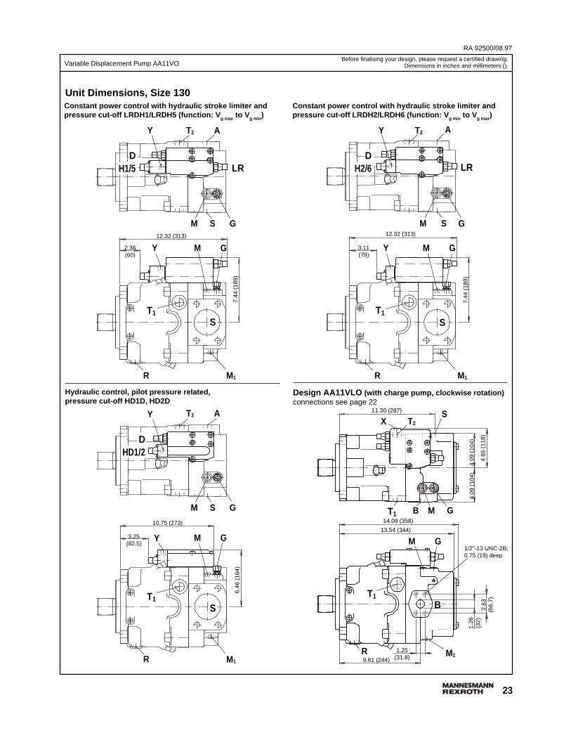
Constant power control with hydraulic stroke limiter andpressure cut-off LRDH1/LRDH5 (function: V g max to Vg min )
Constant power control with hydraulic stroke limiter andpressure cut-off LRDH2/LRDH6 (function: V g min to Vg max )
Hydraulic control, pilot pressure related,pressure cut-off HD1D, HD2D
Design AA11VLO (with charge pump, clockwise rotation)connections see page 22
Unit Dimensions, Size 130
12.32 (313)7.
44 (
189)
T1
R
S
G
MY G
M1
SM
AT2Y
DH1/5 LR
2.36(60)
12.32 (313)
7.44
(18
9)
T1
R
S
G
MY G
M1
SM
AT2Y
DH2/6 LR
3.11(79)
10.75 (273)
6.46
(16
4)
T1
R
S
G
MY G
M1
SM
AT2Y
DHD1/2
3.25(82,5)
14.09 (358)
2.63
(66,
7)
T1
R
B
G
M G
M1
B M
ST2X
13.54 (344)
11.30 (287)
4.09
(10
4)4.
09 (
104)
4.65
(11
8)
T1
1.26
(32)
1.25(31,8)9.61 (244)
1/2"-13 UNC-2B;0.75 (19) deep

RA 92500/08.97
24
Variable Displacement Pump AA11VO
Unit Dimensions, Size 190, design with charge pumpConstant power control, with pressure cut-off and Load sensing valve, LRDSConstant pressure control with Load sensing valve, DRS
T Splined shaft SAE F, 2"pressure angle 30°, 15T-8/16 pitchflat root, side fittolerance class 5, ANSI B92.1a/1976
Connections
A, B Service line ports SAE 11/2" 6000 psi(420 bar) high pressure series
S Suction port SAE 31/2" 500 psi(35 bar) standard series
T1 Air bleed, reservoir 15/16"-12 UNF-2B; 0.79 (20) deepT2 Air bleed, reservoir 15/16"-12 UNF-2B; 0.79 (20) deepM1 Gauge point positioning chamber 9/16"-18 UNF-2B; 0.51 (13) deepM Gauge point for pressure port 9/16"-18 UNF-2B; 0.51 (13) deep
X Port for ∆p-control 9/16"-18 UNF-2B; 0.51 (13) deep
Y Pilot pressure port 9/16"-18 UNF-2B; 0.51 (13) deep
R Air bleed, Oil drain 15/16"-12 UNF-2B; 0.79 (20) deepG Control pressure port 9/16"-18 UNF-2B; 0.51 (13) deep
at design with stroke limiter (H.., U2), or HD, EP-control with fitting GE10 - PLM(in other cases port "G" is plugged)
Shaft ends
S Splined shaft SAE D, 13/4"pressure angle 30°, 13T-8/16 pitchflat root, side fittolerance class 5, ANSI B92.1a/1976
P Parallel shaft, DIN 6885with key AS 16x10x100 (mm)
Before finalising your design, please request a certified drawing.Dimensions in inches and millimeters ().
SDR/DLR
Detail W
5/8"-11 UNC-2B;0.94 (24) deep2.75
(69,9)
clockwise rotation
1.44 (36,5)
15.01 (381,3)
X
G
R
X
SB
4.57
(116
) (S
)4.
57(1
16)
S
Vg min
T1
15.56 (395,3)
7.49 (190,3)
M S G
Vg max
T1 M G
5/8"-11 UNC-2B;0.94 (24) deep
12.57 (319,3) (S)
T2 X S (suction port)
W
R M1
B
7.01
(17
8)6.
50 (
165) Ø
6.50
(Ø
165,
1)
(SA
E-E
)
3.13
(79,
4)
1.50
(38)
2.60
(66)
3.54
(90)
4.75
(120
,7)
M0.63 (15,9)
10.73 (272,5)
8.84 (224,5)
10.33 (262,5)
8.84
(22
4,5)
Note: Thread depth of the S and A/B port bolt holes does not conform to SAEstandards. Please note that shorter bolts and/or `high-collar´ lock washers maybe required.
2.95(75)
1.42(36)2.17(55) 2.64
(67)
ø1.
42(ø
36)
ø4.
96 (
ø12
6)
5/8"
-11
UN
C-2
B
4.45(113)
1.65(42)
M20
ø4.
96 (
ø12
6)
2.16
652.
1658
4.13(105)
(ø55
m6)D
IA
3.46(88)
1.42(36)
2.60(66) 3.15
(80)
ø1.
67(ø
42,3
)
ø4.
96 (
ø12
6)
5/8"
-11
UN
C-2
B
R0.10 (R2,5) R0.16 (R4)
25
Variable Displacement Pump AA11VO
RA 92500/08.97
Before finalising your design, please request a certified drawing.Dimensions in inches and millimeters ().
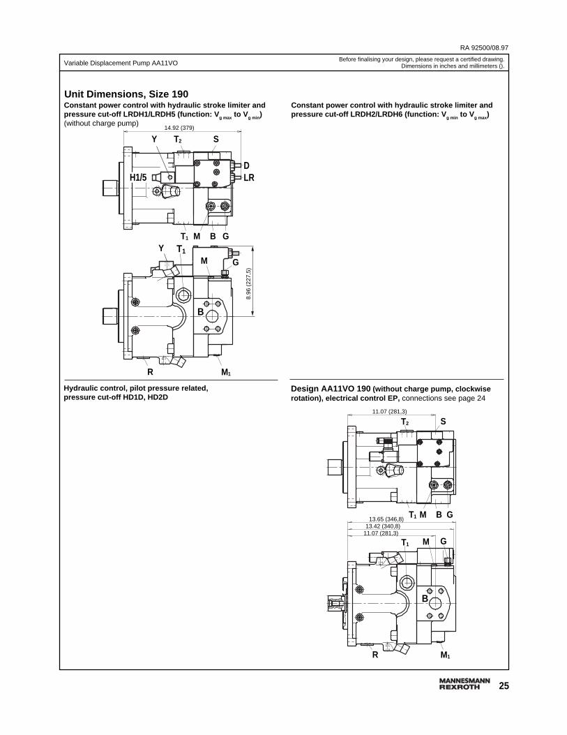
Design AA11VO 190 (without charge pump, clockwiserotation), electrical control EP, connections see page 24
Constant power control with hydraulic stroke limiter andpressure cut-off LRDH1/LRDH5 (function: V g max to Vg min )(without charge pump)
Constant power control with hydraulic stroke limiter andpressure cut-off LRDH2/LRDH6 (function: V g min to Vg max )
Hydraulic control, pilot pressure related,pressure cut-off HD1D, HD2D
Unit Dimensions, Size 190
H1/5
14.92 (379)
8.96
(22
7,5)
T1
R
B
G
MY
G
M1
BMT1
ST2Y
DLR
11.07 (281,3)
T1
R
G
M G
M1
BMT1
ST2
11.07 (281,3)
B
13.42 (340,8)13.65 (346,8)

RA 92500/08.97
26
Variable Displacement Pump AA11VOBefore finalising your design, please request a certified drawing.
Dimensions in inches and millimeters ().
Unit Dimensions, Size 260Electrical control EP, design without charge pump
T Splined shaft SAE 21/4"pressure angle 30°, 17T-8/16 pitchflat root, side fittolerance class 5, ANSI B92.1a/1976
P Parallel shaft, DIN 6885with key AS 18x11x100 (mm)
Shaft endsS Splined shaft SAE D, 13/4"
pressure angle 30°, 13T-8/16 pitchflat root, side fittolerance class 5, ANSI B92.1a/1976
Connections
A, B Service line ports SAE 1 1/2" 6000 psi(420 bar) high pressure series
S Suction port (without charge pump) SAE 3 1/2" 500 psi(35 bar) standard series
S Suction port (with charge pump) SAE 4" 500 psi(35 bar) standard series
T1 Air bleed, reservoir 15/16"-12 UNF-2B; 0.79 (20) deepT2 Air bleed, reservoir 15/16"-12 UNF-2B; 0.79 (20) deepM1 Gauge point positioning chamber 9/16"-18 UNF-2B; 0.51 (13) deepM Gauge point for pressure port 9/16"-18 UNF-2B; 0.51 (13) deepX Port for ∆p-control 9/16"-18 UNF-2B; 0.51 (13) deepY Pilot pressure port 9/16"-18 UNF-2B; 0.51 (13) deepR Air bleed, Oil drain 15/16"-12 UNF-2B; 0.79 (20) deepG Control pressure port 9/16"-18 UNF-2B; 0.51 (13) deep
at design with stroke limiter (H.., U2), or HD, EP-control with fitting GE10 - PLM(in other cases port "G" is plugged)
Note: Thread depth of the S and A/B port bolt holes does not conform to SAEstandards. Please note that shorter bolts and/or `high-collar´ lock washers maybe required.
EP
Detail W5/8"-11 UNC-2B;0.94 (24) deep
2.75(69,9)
clockwise rotation
14.65 (372)
G
R M
SB
5.12
(13
0)
5.22
(13
2,5)
S
Vg min
T1
8.43 (214)
12.09 (307)
M B G
0.63 (15,9) 1.44 (36,5)
Vg max
T1 M G
5/8"-11 UNC-2B;0.83 (21) deep
12.09 (307)
T2
X
S
W
R M
B
7.46
(189
,5)
6.85
(17
4) Ø6.
50 (
Ø16
5,1)
(SA
E-E
)
3.13
(79,
4)
1.50
(38)
2.83
(72)
5.12
(13
0)
4.75
(120
,7)
3.54
(90)
8.84
(22
4,5)
8.84 (224,5)
10.33 (262,5)
2.95(75)
1.42(36)2.17(55) 2.64
(67)
ø1.
42(ø
36)
ø5.
12 (
ø13
0)
5/8"
-11
UN
C-2
B
4.45(113)
1.65(42)
M20
ø5.
12 (
ø13
0)
2.36
342.
3626
4.13(105)
(ø60
m6)D
IA
3.46(88)
1.65(42)
2.60(66) 3.15
(80)
ø1.
91(ø
48,6
)
ø5.
12 (
ø13
0)
3/4"
-10
UN
C-2
B
R0.10 (R2,5) R0.16 (R4)
27
Variable Displacement Pump AA11VO
RA 92500/08.97
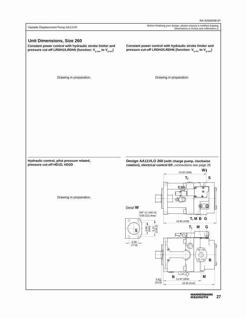
Design AA11VLO 260 (with charge pump, clockwiserotation), electrical control EP, connections see page 26
Constant power control with hydraulic stroke limiter andpressure cut-off LRDH1/LRDH5 (function: V g max to Vg min )
Constant power control with hydraulic stroke limiter andpressure cut-off LRDH2/LRDH6 (function: V g min to Vg max)
Hydraulic control, pilot pressure related,pressure cut-off HD1D, HD2D
Unit Dimensions, Size 260
Before finalising your design, please request a certified drawing.Dimensions in inches and millimeters ().
13.62 (346)
5.13
(130
,2)
T1
R
SG
M
W
G
M
B
MT1
ST2
3.06(77,8)
B16.85 (428)
3.94
(100
)
0.63(15,9)
5/8"-11 UNC-B;0.83 (21) deep
11.97 (304)
16.30 (414)
Detail W
Drawing in preparation. Drawing in preparation.
Drawing in preparation.
RA 92500/08.97
28
Variable Displacement Pump AA11VO
Total length A1
*) design with charge pump (impeller)
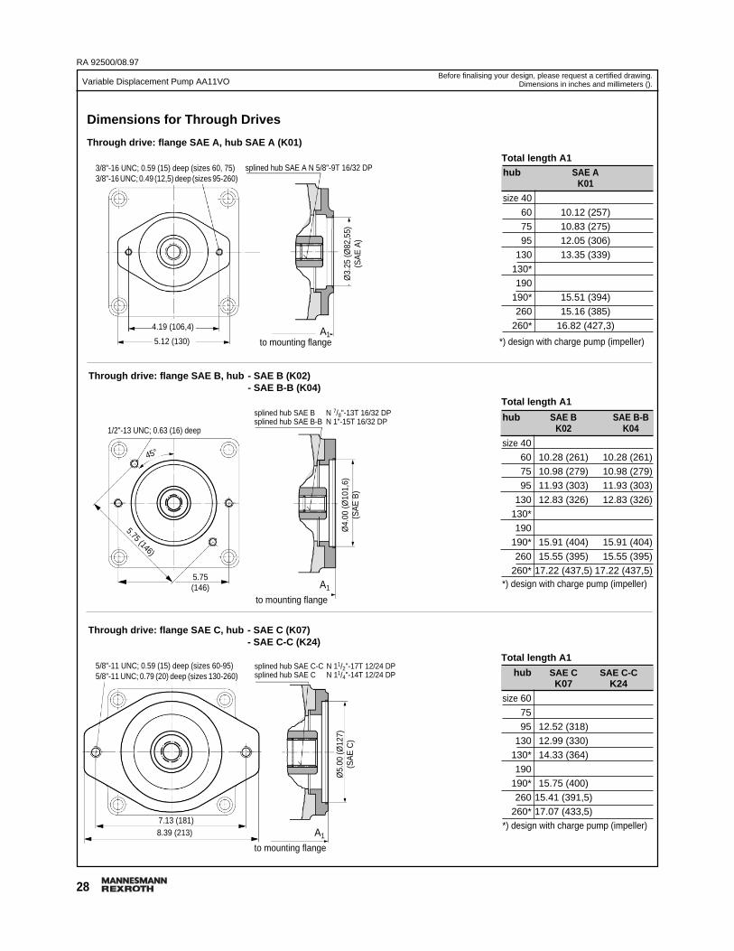
Dimensions for Through Drives
Through drive: flange SAE A, hub SAE A (K01)
Total length A1
Through drive: flange SAE B, hub - SAE B (K02)- SAE B-B (K04)
Total length A1
*) design with charge pump (impeller)
*) design with charge pump (impeller)
hub SAE C SAE C-CK07 K24
size 60
75
95 12.52 (318)
130 12.99 (330)
130* 14.33 (364)
190
190* 15.75 (400)
260 15.41 (391,5)
260* 17.07 (433,5)
hub SAE AK01
size 40
60 10.12 (257)
75 10.83 (275)
95 12.05 (306)
130 13.35 (339)
130*
190
190* 15.51 (394)
260 15.16 (385)
260* 16.82 (427,3)
hub SAE B SAE B-BK02 K04
size 40
60 10.28 (261) 10.28 (261)
75 10.98 (279) 10.98 (279)
95 11.93 (303) 11.93 (303)
130 12.83 (326) 12.83 (326)
130*
190
190* 15.91 (404) 15.91 (404)
260 15.55 (395) 15.55 (395)
260* 17.22 (437,5) 17.22 (437,5)
Before finalising your design, please request a certified drawing.Dimensions in inches and millimeters ().
3/8"-16 UNC; 0.59 (15) deep (sizes 60, 75)3/8"-16 UNC; 0.49 (12,5) deep (sizes 95-260)
5.12 (130) to mounting flange
4.19 (106,4) A1
Ø3.
25 (Ø
82,5
5)(S
AE
A)
splined hub SAE A N 5/8"-9T 16/32 DP
to mounting flange
1/2"-13 UNC; 0.63 (16) deep
5.75(146) A1
5.75 (146)
45°
splined hub SAE B N 7/8"-13T 16/32 DPsplined hub SAE B-B N 1"-15T 16/32 DP
Ø4.
00 (Ø
101,
6)(S
AE
B)
to mounting flange
splined hub SAE C-C N 11/2"-17T 12/24 DPsplined hub SAE C N 11/4"-14T 12/24 DP
7.13 (181)
Ø5.
00 (Ø
127)
(SA
E C
)
5/8"-11 UNC; 0.59 (15) deep (sizes 60-95)5/8"-11 UNC; 0.79 (20) deep (sizes 130-260)
8.39 (213) A1
Through drive: flange SAE C, hub - SAE C (K07)- SAE C-C (K24)
29
Variable Displacement Pump AA11VO
RA 92500/08.97
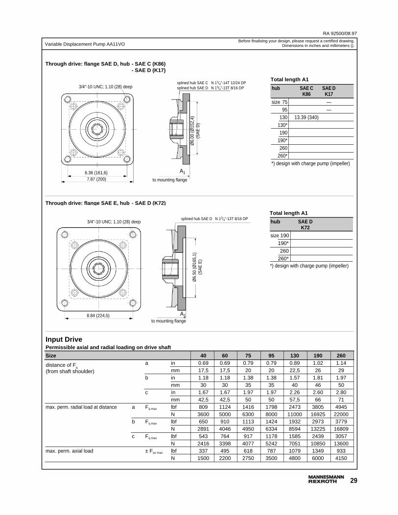
hub SAE C SAE DK86 K17
size 75 —
95 —
130 13.39 (340)
130*
190
190*
260
260*
Size 40 60 75 95 130 190 260a in 0.69 0.69 0.79 0.79 0.89 1.02 1.14
mm 17,5 17,5 20 20 22,5 26 29b in 1.18 1.18 1.38 1.38 1.57 1.81 1.97
mm 30 30 35 35 40 46 50c ín 1.67 1.67 1.97 1.97 2.26 2.60 2.80
mm 42,5 42,5 50 50 57,5 66 71max. perm. radial load at distance a Fq max lbf 809 1124 1416 1798 2473 3805 4945
N 3600 5000 6300 8000 11000 16925 22000b Fq max lbf 650 910 1113 1424 1932 2973 3779
N 2891 4046 4950 6334 8594 13225 16809c Fq max lbf 543 764 917 1178 1585 2439 3057
N 2416 3398 4077 5242 7051 10850 13600max. perm. axial load ± Fax max lbf 337 495 618 787 1079 1349 933
N 1500 2200 2750 3500 4800 6000 4150
Total length A1
*) design with charge pump (impeller)
Through drive: flange SAE D, hub - SAE C (K86)- SAE D (K17)
Total length A1
*) design with charge pump (impeller)
distance of Fq
(from shaft shoulder)
Input DrivePermissible axial and radial loading on drive shaft
Through drive: flange SAE E, hub - SAE D (K72)
hub SAE DK72
size 190
190*
260
260*
Before finalising your design, please request a certified drawing.Dimensions in inches and millimeters ().
splined hub SAE C N 11/4"-14T 12/24 DPsplined hub SAE D N 13/4"-13T 8/16 DP3/4"-10 UNC; 1.10 (28) deep
Ø6.
00 (Ø
152,
4)(S
AE
D)
to mounting flange
6.36 (161,6)7.87 (200)
splined hub SAE D N 13/4"-13T 8/16 DP3/4"-10 UNC; 1.10 (28) deep
Ø6.
50 (Ø
165,
1)(S
AE
E)
8.84 (224,5)to mounting flange
A1
A1

RA 92500/08.97
30
Variable Displacement Pump AA11VO
Summary of the Assembly Possibilities for AA11VO
Through drive (AA11VO) A10VO assembly possibilities (2nd pump)hub flange AA11VO AA10V(S)O A10VG AA4VG others available for (see page 3):
K01 SAE A SAE A size 10,18 G2 AA11VO 40...260
K02 SAE B SAE B size 28 size 18 G3 AA11VO 40...260
K04 SAE B-B SAE B size 40 size 45 size 28, 45 size 28 AA11VO 40...260
K07 SAE C SAE C size 60 size 60, 71 size 40, 56, 71 AA11VO 60...260
K86 SAE C SAE D size 75 AA11VO 75...260
K24 SAE C-C SAE C size 100 AA11VO 95...260
K17 SAE D SAE D size 95, 130 size 140 size 90, 125 AA11VO 130...260
K72 SAE D SAE E size 190, 260 size 180 AA11VO 190...260
Combination Pumps
When ordering combination pumps the ordering codes have to be connected by a "+" sign:"ordering code 1st pump" +" ordering code 2nd pump"
Example: AA11VO130LRDS/10R-SD62K07 + AA11VO60LRDS/10R-SC62N00
31
Variable Displacement Pump AA11VO
RA 92500/08.97
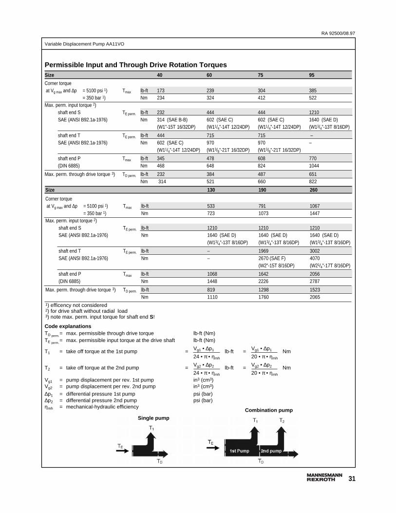
Permissible Input and Through Drive Rotation TorquesSize 40 60 75 95
Corner torque at Vg max and ∆p = 5100 psi 1) Tmax lb-ft 173 239 304 385
= 350 bar 1) Nm 234 324 412 522Max. perm. input torque 2)
shaft end S TE perm. lb-ft 232 444 444 1210SAE (ANSI B92.1a-1976) Nm 314 (SAE B-B) 602 (SAE C) 602 (SAE C) 1640 (SAE D)
(W1"-15T 16/32DP) (W11/4"-14T 12/24DP) (W11/4"-14T 12/24DP) (W13/4"-13T 8/16DP)
shaft end T TE perm. lb-ft 444 715 715 –SAE (ANSI B92.1a-1976) Nm 602 (SAE C) 970 970 –
(W11/4"-14T 12/24DP) (W13/8"-21T 16/32DP) (W13/8"-21T 16/32DP)
shaft end P Tmax lb-ft 345 478 608 770(DIN 6885) Nm 468 648 824 1044
Max. perm. through drive torque 3) TD perm. lb-ft 232 384 487 651Nm 314 521 660 822
Code explanationsTD perm.
= max. permissible through drive torque lb-ft (Nm)TE perm.
= max. permissible input torque at the drive shaft lb-ft (Nm)
Vg1 • ∆p1 Vg1 • ∆p1T1 = take off torque at the 1st pump = lb-ft = Nm24 • π • ηmh 20 • π • ηmh
Vg2 • ∆p2 Vg2 • ∆p2T2 = take off torque at the 2nd pump = lb-ft = Nm24 • π • ηmh 20 • π • ηmh
Vg1 = pump displacement per rev. 1st pump in3 (cm3)Vg2 = pump displacement per rev. 2nd pump in3 (cm3)∆p1 = differential pressure 1st pump psi (bar)∆p2 = differential pressure 2nd pump psi (bar)ηmh = mechanical-hydraulic efficiency
Size 130 190 260
Corner torque at Vg max and ∆p = 5100 psi 1) Tmax lb-ft 533 791 1067
= 350 bar 1) Nm 723 1073 1447Max. perm. input torque 2)
shaft end S TE perm. lb-ft 1210 1210 1210SAE (ANSI B92.1a-1976) Nm 1640 (SAE D) 1640 (SAE D) 1640 (SAE D)
(W13/4"-13T 8/16DP) (W13/4"-13T 8/16DP) (W13/4"-13T 8/16DP)
shaft end T TE perm. lb-ft – 1969 3002SAE (ANSI B92.1a-1976) Nm – 2670 (SAE F) 4070
(W2"-15T 8/16DP) (W21/4"-17T 8/16DP)
shaft end P Tmax lb-ft 1068 1642 2056(DIN 6885) Nm 1448 2226 2787
Max. perm. through drive torque 3) TD perm. lb-ft 819 1298 1523Nm 1110 1760 2065
1) efficency not considered2) for drive shaft without radial load3) note max. perm. input torque for shaft end S!
Single pump
Combination pump
RA 92500/08.97
32
Variable Displacement Pump AA11VO
All rights reserved - Subject to revisionPrinted in U.S.A.
Mannesmann Rexroth Corporation Rexroth Hydraulics Div., Industrial, 2315 City Line Road, Bethlehem, PA 18017-2131 Tel. (610) 694-8300 Fax: (610) 694-8467Rexroth Hydraulics Div., Mobile, 1700 Old Mansfield Road, Wooster, OH 44691-0394 Tel. (330) 263-3400 Fax: (330) 263-3333