variable area flowmeter type 250 instruction manual -...
TRANSCRIPT

Houdec Instrument SAS
Instruction Manual 50466-101 October 2008 Variable area flowmeter
Variable area flowmeter type 250 Instruction Manual
1.GENERAL page 2
1.1. Description page 2
1.2. Measurement principle page 2
1.3. Flow rates page 2
1.4. Technical specifications page 2
1.5. Design of the instrument page 3
2. INSTALLATION page 4
2.1. Prior conditions page 4
2.2. Pipework preparation page 4
2.3. Preparing the flowmeter for use page 4
3. INSTRUCTION SPECIFIC TO ATEX page 5
3.1. Flame-proof version page 5
3.2. Intrinsic safety version page 5
4. FITTING page 6
5. OPERATION page 5
6. CHECKING CORRECT OPERATION page 7
6.1. Checking the indicator unit page 7
6.2. Checking the measurement body page 7
7. WIRING AND USE OF ALARMS page 8
7.1. Description page 8
7.2. Technical characteristics page 8
7.3. Wiring / Settings page 8
8. ELECTRONIC TRANSMITTER page 9
8.1. Description page 9
8.2. technical characteristics page 9
8.3. Wiring / Settings page 9
9. REPLACEMENT OF MAIN COMPONENTS page 10
9.1. Replacing the float page 10
9.2. Replacing the indicator unit case assembly page 10
9.3. Replacing the graduated dial page 10
9.4. Replacing the dial pointer page 10
9.5. Replacing an alarm contact page 10
9.6. Replacing an electronic transmitter page 11
9.6.1. Standard type with I250Housing page 11
9.6.2. Type 250B4 page 11
9.6.3. Type 250Ti page 11
10. LIST OF SPARE PARTS page 12
11. WARRANTY page 12

Variable area flowmeter
Instruction Manual 50466-101
October 2008
Page 2
1. GENERAL
1.1. DESCRIPTION
Flow meter type 250 consists of a 316L stainless steel body containing the measuring elements (taper + float with calibrated measurement disk) and an indicator unit which can be fitted with alarms or a transmitter. There is a version with PTFE lining (all parts in contact with the fluid are PTFE) for very corrosive products. The instrument is factory calibrated using reference fluids, water for liquid flow rates and air for gas flow rates. Flow rate corrections are performed in advance by computer in order to take account of users actual operating conditions.
1.2. MEASUREMENT PRINCIPLE
The instrument is mounted vertically and the fluid flow (in ascending direction) includes a vertical force on the float which moves upwards. The cross-section oft the passage between the measurement disk and the conical part of the body increases uniformly. For a given flow rate, the float stabilizes at a height which corresponds to a cross-section where the fluid thrust is balanced by the weight of the float. Indication of the flow rate is transmitted by magnetic coupling to the dial of the indicator unit
1.3. FLOW RATES
STAINLESS STEEL VERSION PTFE VERSION
ND LIQUIDS flow rates GAS Flow capacity m3/h Pressure drop LIQUIDS flow rates Pressure drop
Code d=1 Code Air @ 20°C, 1013 mbar abs mbar Code mbar
15 (½")
M1 10-100 L/h 35
M2 16-160 L/h MG2 5 60 MP2 16-160 L/h 77
M3 25-250 L/h MG3 7,5 60 MP3 25-250 L/h 70
M4 40-400 L/h MG4 12 60 MP4 40-400 L/h 70
M5 60-600 L/h MG5 18 65 MP5 60-600 L/h 77
M6 0,1-1 m3/h MG6 30 70 MP6 0,1-1 m3/h 80
25 (1")
M5 60-600 L/h MG5 18 45 MP5 60-600 L/h 45
M6 0,1-1 m3/h MG6 30 80 MP6 0,1-1 m3/h 45
M7 0,16-1,6 m3/h MG7 48 55 MP7 0,16-1,6 m3/h 79
M8 0,25-2,5 m3/h MG8 75 80 MP8 0,25-2,5 m3/h 45
M9 0,4-4 m3/h MG9 120 85 MP9 0,4-4 m3/h 84
M10 0,6-6 m3/h MG10 180 125
50 (2")
M8 0,25-2,5 m3/h MG8 75 55 MP8 0,25-2,5 m3/h 48
M9 0,4-4 m3/h MG9 120 80 MP9 0,4-4 m3/h 92
M10 0,6-6 m3/h MG10 180 55 MP10 0,6-6 m3/h 48
M11 1-10 m3/h MG11 300 80 MP11 1-10 m3/h 95
M12 1,6-16 m3/h MG12 480 95
M13 2,5-25 m3/h MG13 750 130
80 (3") or
100
M11 1-10 m3/h MG11 300 60 MP10 0,6-6 m3/h 50
M12 1,6-16 m3/h MG12 480 90 MP11 1-10 m3/h 95
M13 2,5-25 m3/h MG13 750 60 MP12 1,6-16 m3/h 55
M14 4-40 m3/h MG14 1000 125 MP13 2,5-25 m3/h 100
M15 5-50 m3/h - - 140 -
M16 6-60 m3/h - - 165 -
M17 8-80 m3/h - - 220 -
Approx. weight : DN15(1/2") = 4,5kg DN25(1")=5kg DN50(2")=8,5kg DN80(3")=15kg DN100(4")=18,5kg
1.4. TECHNICAL SPECIFICATIONS
● Accuracy : 2% of maximum flow rate (PTFE 3%) (class 1.6 VDI; VDE 3513 on request). ● Scale ratio: 1 to 10 ● Operating pressure: NP16 (NP40 on request for ND15 to ND 8O) ● Operating temperature: - Stainless steel version: -40 to +200°C
o heat shield required depending on option o high temperature versions on request
- PTFE version: -20 to +125°C
● Materials: wetted parts (body and float assembly) Z2 CND Stainless steel (316L) indicator housing (IP65) aluminium version : mounting plate in aluminium alloy, front cover in cast aluminium alloy, epoxy/polyester paint stainless steel version : mounting plate and front cover in 316L stainless steel (not painted in standard). N.B.: With liquids, the operating pressure must be at least equal to twice the instrument pressure drop. With gases, this must be at least 5 times.

Instruction Manual 50466-101 October 2008 Variable area flowmeter
Page 3
1.5. DESIGN OF THE INSTRUMENT
Each instrument is composed of two main parts, the body and the indicator unit. These two elements are assembled and calibrated in the factory. Each instrument has an unique serial number (punched on the bracket welded to the body and inscribed on the rear and on the dial of the indicator unit). This serial number must be quoted with any request for information from the factory after-sales department. If any disassembly and reassembly occurs, the body and indicator unit must have the same serial number in order to ensure the correct measurement is indicated. The body consists of three main parts: the measurement tube fitted with coupling flanges, the float and the two guide end stops (see sketch opposite). The upper part of the float has a hexagonal guide pin to prevent rotation (or helicoidally for the gas version). At the rest position, the arrow engraved at the end of this guide must be oriented towards the magnetic exten-sion of the indicator unit. The indicator unit has a main shaft mounted on precision bearings on which the receiver magnet is fixed (inside the magnetic extension), the indicator needle, the eddy current damper and the alarm and/or transmitter control cams (inside the indicator unit).
1.6. DIMENSIONS
Reading pointer
Float guide
pin
Float
Control magnet
Measurement
disk
Strengthening disk Guide/
End stop
Upper alarm
adjustment
Graduated dial
Lower alarm adjustment

Variable area flowmeter
Instruction Manual 50466-101
October 2008
Page 4
2. INSTALLATION
2.1. PRIOR CONDITIONS
Ensure that all safety regulations are observed, in particular those relating to hazardous areas. As far as inherent safety is concerned, check that the classification of the instrument corresponds to the classification required at the installation site. The instrument must only be mounted in a precisely vertical position.
IMPORTANT NOTE:
In order not to disturb the magnetic coupling an area of about 200mm free from any magnetic component a field must be provided all around the indicator unit extension.
Pressure adjusting valves should preferably be placed downstream of the instrument (at a minimum distance of 200mm after the coupling flange). This rule is particularly recommended for gases (in order to prevent any reading error due to modification to the operating pressure for which the instrument has been calibrated).
It is recommended that a straight length of about 5 times the diameter of the pipe is provided on the upstream side, and for about 200mm on the downstream side.
2.2. GENERAL
This equipment must only be handled empty, with all essential precautions taken to avoid impact or major stresses, which would be likely to alter its geometry and damage internal measuring devices, or the contact pattern of the connecting component seals. The various parts must be connected without engendering any mechanical or other stresses, other than those provided for when installing the equipment, and sealing the connection. Under no circumstances must the equipment be used as a support or for mounting any part or component not originally provided for. Welding is prohibited. If welded connections or fastenings are required by the equipment definition, these must be produced by qualified personnel, using recognized operating procedures and the required materials, meeting current standards. Grinding, cutting or heating are prohibited on any parts of the equipment which are subject to pressure. Make the connections using seals suitable for the fluid contained and the type of connection required. For flanges, make sure the seals used are new, compatible with the seal contact pattern and the service pressure and temperature. Use standard fastenings which match the flange rating and service conditions required by the type of seal and the process. After verifying the condition of the seal contact pattern, tighten the bolts in several stages (see fig.3), using appropriate tools, torque or pneumatic wrench and respecting the torque settings recommended by the seal manufacturer. Run a prior tightness test under service conditions before commissioning the equipment.
fig.3. Correct flange bolts tightening sequence
2.3. PIPEWORK PREPARATION
Before fitting the instrument into the pipe work the latter must be carefully cleaned in order to remove any debris which might be present and especially magnetic particles liable to be attracted by the float magnet.
Ensure that the rated dimensions of the coupling flanges match those of the instrument and that the pipes are sufficiently rigid and properly secured in order to prevent vibration being transmitted to the instrument.
2.4. PREPARING THE FLOWMETER FOR
USE
Remove all temporary protection, fixing or blanking items.
Check that the inside of the body is dean and that the float moves freely over its full travel (the indicator needle must follow the float movement with no sticking points).
1 7
4
6
5
3
8 2
1
2
3
4

Instruction Manual 50466-101 October 2008 Variable area flowmeter
Page 5
3. INSTRUCTION SPECIFIC TO HAZARDOUS AREA INSTALLATIONS
3.1. FLAME-PROOF VERSION
(apply to the flame-proof detection box type B4: certificate number LCIE01ATEX6060X)
BEFORE ANY INTERVENTION ON THE INSTRUMENT, USUAL PRECAUTIONS SHOULD BE
TAKEN.
- POWER SUPPLY SHOULD BE SWITCHED OF BEFORE ANY INTERVENTION. FLAME-PROOF HOUSING MUST NOT BE OPENED WHILE ENERGIZED.
- Always refer to the safety specifications instructions of the installation place and more particularly with regard to the hazardous zones as well as the dangerous products.
- The level switch can be used with flammable gases and vapors belonging to groups IIA, IIB and IIC and temperatures class of T6. - The installation of the instrument will be carried out by sorted personnel in conformity with the local installation standards.
- The customer is responsible of the compatibility of connections of the instrument with the process
- conditions, with the sealing joint regarding the flange and of the electric connection in compare with the technical data of the instrument.
3.2. INTRINSIC SAFETY VERSION
(apply to the Indicator/transmitter housing I250: certificate number LCIE01ATEX6063X)
BEFORE ANY INTERVENTION ON THE INSTRUMENT, USUAL PRECAUTIONS SHOULD BE TAKEN.
- Always refer to the safety specifications instructions of the installation place and more particularly with regard to the hazardous zones as well as the dangerous products.
- The level indicator can be used with flammable gases and vapors belonging to groups IIA, IIB and IIC and class temperatures of T6.
- The installation of the instrument will be carried out by sorted personnel in conformity with the local installation standards.
- The customer is responsible of the compatibility of connections of the instrument with the process conditions, with the sealing joint regarding the flange and of the electric connection in compare with the technical data of the instrument
For ATEX instruments installation, read the attached leaflet
“safety instructions for detection box type B4 “
For ATEX instruments installation, read the attached leaflet
“safety instructions for detection box type B4 or indicator housing type I250”.
Variable area flowmeter
Instruction Manual 50466-101
October 2008
Page 6
4. FITTING
Fit the flow meter into the pipe work, inserting appropriate seals (not supplied) between the flanges. Ensure that the coupling flanges are parallel to those on the instrument and that the distance between centers is suitable in order to avoid strain other than that needed to provide sealing.
Tighten the bolts to obtain a sealed joint (retighten after a period of operation if necessary). When fitting the instrument with PTFE lining, special precautions must be taken as PTFE is readily distorted when cold; the recommended tightening torques below should not be exceeded: DN15:lONm DN2O:2ONm DN5O:4ONm DN8O:5ONm Important note: The PTFE gasket must have the same dimensions of the flow meter flange raised face and perfectly centered before tightening.
ESSENTIAL SAFETY REQUIREMENTS
Instruments must be mounted vertically in rigidly fixed pipelines
Sudden changes of pipe section at inlet or fittings that cause violent flow disturbances must be avoided.
Care must be taken to avoid inducing torsion stress on flow meter when installing into the pipeline.
Prior to installation ensure pipelines are flushed/drained to ensure they are free from any solid particles & pressure.
Ensure pipelines are fully primed before commencing normal use.
Valves must be opened or closed progressively to avoid shock/vibration.
Do not exceed maximum working pressure as stated on the label.
Only use with the fluid/gas stated on the label.
Solvents must not be used to clean the protective cover.
Do not exceed min/max. working temperature as stated in manual.
Do not subject meter to sudden/extreme changes of temperature.
The meter is regularly inspected for corrosion & wear.
5. OPERATION
SAFETY WITH REGARD TO PRESSURE This pressurized equipment is part of a unit, so the integrator must fit the installation with safety devices (valves, rupture disk, sensor,…) to protect the equipment against the risk of excess pressure. The opening pressure of these devices must equal the maximum allowable pressure (PS) of the equipment. These mechanisms must also allow evacuation of full-flow steam under rated calculated conditions. The exhaust must be piped freely and without danger to personnel or the environment. The integrator must also provide a device for measuring residual pressure in the equipment (pressure gauge …) and a bleeder (piped if the product so requires), to guarantee the safety of personnel working on the equipment. Isolation valves are recommended to be installed between the equipment and the unit to which it is mounted, so that maintenance operations can be performed. Any other way ( or design ) may be achieved if they provide a acceptable safety level in accordance with the Directive 97/23/EC and/or present standards
SAFETY WITH REGARDS TO TEMPERATURE
As far as this pressurized equipment is a part of an unit, all required measures regarding risks induced by temperature (regarding working personnel and the type of the material around according to the device’s specification) shall be taken by the integrator. For example, a kind of protection could be achieved, by the insulation of warm components, by using protection devices for access, or using any other devices suitable with the site of the unit and standards in force. Do not either subject the instrument to significant temperature variations or fire exposure.
OPENING AND CLOSING OF PRESSURIZED EQUIPMENT
Prior to any action on a pressurized equipment, the suitability of pressure and temperature conditions with thought operations must be checked by the permitted and qualified technician. Regarding equipments fitted with alarm switches, use shall be made with care : voltage, current, devices ( or security devices ) controlled by theses switches… Appropriate tools must be used when stripping parts to get access to the pressurized equipment. Refer to drawings or appropriate instruction note. Gaskets could be replaced if needed, check for bolt tightening… Security rules must be checked (even for new devices) by the operator before pressurize. perating conditions must comply with the instructions given. This equipment must not contain any fluid other than that (or those) for which it is designed. It is strictly prohibited to make any temporary or permanent modification, or to perform any operation likely to alter the physical, mechanical or metallurgical characteristics of any part, without the manufacturer's prior written agreement. A danger analysis has been performed, in accordance with appendix I of Directive 97/23/EC, based on the information provided. Any change with respect to this information, likely to call into question the safety of using the equipment, can only be made outside the manufacturer's responsibility. efore commissioning, the operator must make sure that the safety regulations applicable to pressurized equipment are respected and that the connected components work properly. This equipment is designed for static loads appropriate for the device's own weight and the specific stresses due to pressure and temperature as defined in the specifications. No additional load or stresses due to vibrations are accounted for, unless this is specifically agreed during the preliminary studies.

Instruction Manual 50466-101 October 2008 Variable area flowmeter
Page 7
6. CHECKING CORRECT OPERATION
This equipment was built in accordance with the essential safety regulations defined in the "Pressurized Equipment Directive" 97/23/EC, and taking into account the information provided with the order. It was designed, manufactured and carefully tested for the application as defined. It must be used in accordance with the information provided in the above-mentioned order. The operator should periodically verify the equipment's ability to continue in service. Periodic monitoring and inspections must be made in accordance with current regulations in the country in which the equipment is used. This instrument is designed and calculated with a defined corrosion allowance. It is up to the user to check it periodically (according to the corrosiveness of fluids or the processes used) for any reduction in this allowance in the main components of the instrument, so that any steps needed to maintain it's durability and resulting safety, can be taken. MAINTENANCE : This instrument is maintenance-free during normal operation. However, it should be cleaned at regular intervals if it is used with fluids which contain sediment or other deposits.
Before fully withdrawing the instrument from the line, it is advisable to check that
the indicator is operating correctly:
If the instrument appears to be functioning incorrectly in use, carry out the following checks:
6.1. CHECKING THE INDICATOR UNIT
Remove the indicator unit from the body of the instrument after having undone the two fixing screws situated at the rear of the unit either side of the magnetic transmission boss.
Take off the cover. Keeping the indicator in the vertical position (normal operating position)
carefully check manually that the needle moves. This must move over the full scale of the indicator evenly, without sticking and with a minimum friction torque. If movement is defective, cheek the play between the moving parts fixed to the needle shaft and the fixed parts of the indicator (eddy current damper, alarm, switch cams...). If there are persistent sticking points the instrument may need to be returned to the factory for the bearings of the control shaft to be replaced. If operation of the indicator is satisfactory, check the measurement body.
6.2. CHECKING THE MEASUREMENT BODY
After having isolated the line remove the measurement body. Check the movement of the float manually; this must move evenly,
without sticking and with a minimum of friction. If necessary, take the float out of the body to check for any faults or to
dean it completely in order to remove deposits.
FOR THE PROCEDURE FOR DISASSEMBLY/REASSEMBLY 0F THE ABOVE PARTS
REFER TO THE CHAPTER ON INTERCHANGEABILITY / REPLACEMENT 0F PRINCIPAL COMPONENTS.
Variable area flowmeter
Instruction Manual 50466-101
October 2008
Page 8
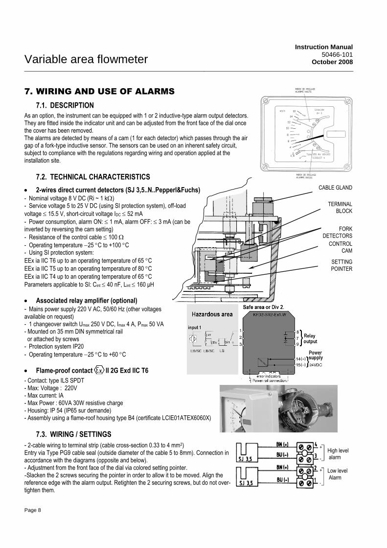
TERMINAL
BLOCK
FORK
DETECTORS
SETTING
POINTER
CONTROL
CAM
CABLE GLAND
7. WIRING AND USE OF ALARMS
7.1. DESCRIPTION
As an option, the instrument can be equipped with 1 or 2 inductive-type alarm output detectors. They are fitted inside the indicator unit and can be adjusted from the front face of the dial once the cover has been removed. The alarms are detected by means of a cam (1 for each detector) which passes through the air gap of a fork-type inductive sensor. The sensors can be used on an inherent safety circuit, subject to compliance with the regulations regarding wiring and operation applied at the installation site.
7.2. TECHNICAL CHARACTERISTICS
2-wires direct current detectors (SJ 3,5..N..Pepperl&Fuchs) - Nominal voltage 8 V DC (Ri ~ 1 k) - Service voltage 5 to 25 V DC (using SI protection system), off-load
voltage 15.5 V, short-circuit voltage IDC 52 mA
- Power consumption, alarm ON: 1 mA, alarm OFF: 3 mA (can be inverted by reversing the cam setting)
- Resistance of the control cable 100
- Operating temperature 25 C to +100 C - Using SI protection system:
EEx ia IIC T6 up to an operating temperature of 65 C
EEx ia IIC T5 up to an operating temperature of 80 C
EEx ia IIC T4 up to an operating temperature of 65 C
Parameters applicable to SI: Cint 40 nF, Lint 160 μH
Associated relay amplifier (optional) - Mains power supply 220 V AC, 50/60 Hz (other voltages available on request) - 1 changeover switch Umax 250 V DC, Imax 4 A, Pmax 50 VA - Mounted on 35 mm DIN symmetrical rail or attached by screws - Protection system IP20
- Operating temperature 25 C to +60 C
Flame-proof contact II 2G Exd IIC T6
- Contact: type ILS SPDT - Max: Voltage : 220V - Max current: lA - Max Power : 60VA 30W resistive charge - Housing: IP 54 (IP65 sur demande) - Assembly using a flame-roof housing type B4 (certificate LCIE01ATEX6060X)
7.3. WIRING / SETTINGS
- 2-cable wiring to terminal strip (cable cross-section 0.33 to 4 mm2) Entry via Type PG9 cable seal (outside diameter of the cable 5 to 8mm). Connection in accordance with the diagrams (opposite and below). - Adjustment from the front face of the dial via colored setting pointer. -Slacken the 2 screws securing the pointer in order to allow it to be moved. Align the reference edge with the alarm output. Retighten the 2 securing screws, but do not over-tighten them.
High level alarm Low level
Alarm
Upper alarm setting pointer
Lower alarm setting pointer
Instruction Manual 50466-101 October 2008 Variable area flowmeter
Page 9
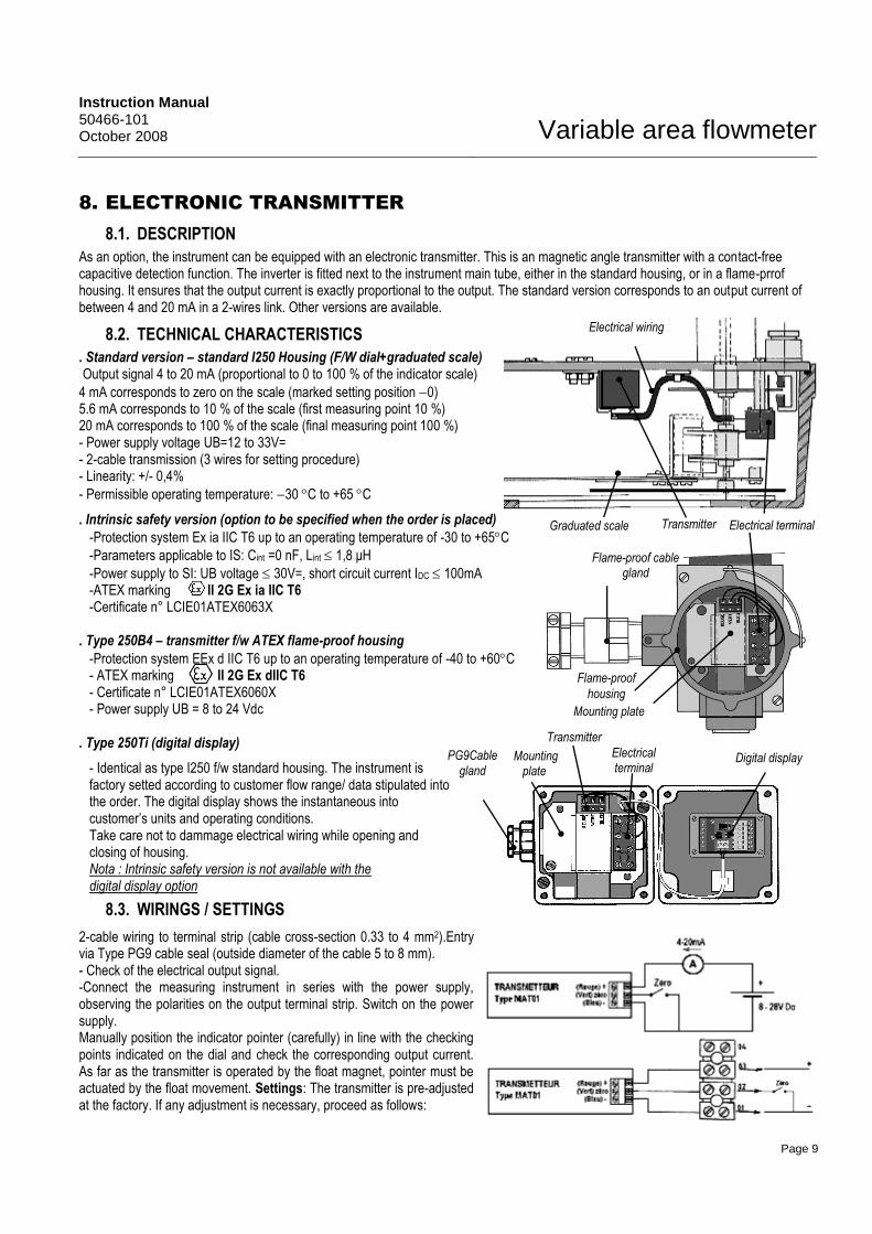
8. ELECTRONIC TRANSMITTER
8.1. DESCRIPTION
As an option, the instrument can be equipped with an electronic transmitter. This is an magnetic angle transmitter with a contact-free capacitive detection function. The inverter is fitted next to the instrument main tube, either in the standard housing, or in a flame-prrof housing. It ensures that the output current is exactly proportional to the output. The standard version corresponds to an output current of between 4 and 20 mA in a 2-wires link. Other versions are available.
8.2. TECHNICAL CHARACTERISTICS
. Standard version – standard I250 Housing (F/W dial+graduated scale) Output signal 4 to 20 mA (proportional to 0 to 100 % of the indicator scale)
4 mA corresponds to zero on the scale (marked setting position 0) 5.6 mA corresponds to 10 % of the scale (first measuring point 10 %) 20 mA corresponds to 100 % of the scale (final measuring point 100 %) - Power supply voltage UB=12 to 33V= - 2-cable transmission (3 wires for setting procedure) - Linearity: +/- 0,4%
- Permissible operating temperature: 30 C to +65 C
. Intrinsic safety version (option to be specified when the order is placed)
-Protection system Ex ia IIC T6 up to an operating temperature of -30 to +65C
-Parameters applicable to IS: Cint =0 nF, Lint 1,8 μH
-Power supply to SI: UB voltage 30V=, short circuit current IDC 100mA -ATEX marking II 2G Ex ia IIC T6 -Certificate n° LCIE01ATEX6063X
. Type 250B4 – transmitter f/w ATEX flame-proof housing
-Protection system EEx d IIC T6 up to an operating temperature of -40 to +60C - ATEX marking II 2G Ex dIIC T6 - Certificate n° LCIE01ATEX6060X - Power supply UB = 8 to 24 Vdc
. Type 250Ti (digital display)
- Identical as type I250 f/w standard housing. The instrument is factory setted according to customer flow range/ data stipulated into the order. The digital display shows the instantaneous into customer’s units and operating conditions. Take care not to dammage electrical wiring while opening and closing of housing. Nota : Intrinsic safety version is not available with the digital display option
8.3. WIRINGS / SETTINGS
2-cable wiring to terminal strip (cable cross-section 0.33 to 4 mm2).Entry via Type PG9 cable seal (outside diameter of the cable 5 to 8 mm). - Check of the electrical output signal. -Connect the measuring instrument in series with the power supply, observing the polarities on the output terminal strip. Switch on the power supply. Manually position the indicator pointer (carefully) in line with the checking points indicated on the dial and check the corresponding output current. As far as the transmitter is operated by the float magnet, pointer must be actuated by the float movement. Settings: The transmitter is pre-adjusted at the factory. If any adjustment is necessary, proceed as follows:
Transmitter
Electrical wiring
Electrical terminal
Graduated scale
Transmitter Electrical
terminal
Flame-proof
housing
Flame-proof cable gland
Mounting plate
Mounting plate
PG9Cable gland
Digital display

Variable area flowmeter
Instruction Manual 50466-101
October 2008
Page 10
9. REPLACEMENT OF MAIN COMPONENTS
The following components of the instrument are interchangeable:
-Float, -Indicator unit, - indicator unit assembly- cover assembly, - graduated dial, - dial pointer, -
alarm,contact ,- transmitter - It is essential to quote the serial number of the instrument (a 6-digit number engraved on the forward part of the mounting bracket of the indicator unit and printed on the dial of the indicator unit and on the float) when ordering spare parts. -In every case during a maintenance operation and, in particular, when working on the indicator unit, ensure that the components of the magnetic link of the instrument do not come into contact with magnetic components (tools) or
magnetic fields. The resistive load of the magnets is precisely adjusted at the factory and should not be altered. Safety : Before carrying out any kind of work on the instrument, the following precautions must be taken * Always refer to the safety regulations in force at the installation site, with particular regard to areas containing an explosive atmosphere and hazardous products. * Disconnect the instrument from the electrical power supply before opening the protective cover. * If it is necessary to perform tests while voltage is applied, they must be carried out by qualified personnel who are familiar with the potential hazards
9.1. REPLACING THE FLOAT
- Remove the instrument from the line. - Using pliers unlock the clamp for the upper guide
(see sketch) - Squeeze the two lugs on
the clamp to free the catches and remove the clamp
- Remove the float - proceed to replace the
float taking care not to damage the edge of the measurement disk.
- When refitting the float the arrow punched on the upper guide rod must be oriented in the direction of the indicator unit magnetic extension
- Refit the guide clamp ( preferably with a new one). The catches must go into the bottom of the notch.
- Lock the lugs using pliers. The end of the lugs must be against the part opposite the clamp for positive locking.
- Manually check the correct movement of the float over its full stroke.
N.B. in the standard version (no damper), the upper and lower guides are identical.
9.2. REPLACING THE INDICATOR UNIT CASING ASSEMBLY
The casing is attached by 2 screws to the mounting lug welded to the body. Once the casing has been replaced, the zero position must be reset (refer to Paragraph 9).
9.3. REPLACING THE GRADUATED DIAL
The graduated dial must be replaced by an identical type of graduated dial. The serial number of the instrument must be quoted in order to ensure that the identical type of dial is supplied (computerized stock control). It may be necessary to reset the zero position (refer to Paragraph 9.7).
9.4. REPLACING THE DIAL POINTER
The dial pointer is fixed to the indicator shaft using an M3 grub screw. Reposition the new pointer against the mechanical stop marker when the float is in rest position against the stop on the lower guide. If the instrument is fitted with a transmitter unit, it is necessary to loosen the lower pointer stop in order to perform the adjustment; next reset the pointer end stop on order to obtain transmitter zero (position-0) when the instrument is at rest.
9.5. REPLACING AN ALARM CONTACT
- Remove the graduated dial. - Disconnect the faulty contact from its terminal strip (after isolating the unit from the power supply). - Remove the mounting bracket from the graduated dial by slackening the 2 screws securing the pointer. Mark the direction and the position of the contact on the mounting bracket. - Replace the contact (the securing screw is accessible through the slot in the detector). -Reassemble the mounting bracket and contact at the rear of the dial, passing it through the circular cut-out, and secure it, together with the pointer, to the front face by means of 2 M3 screws. -Reconnect the cables between the contact and the terminal strip, noting the cable colours shown on the wiring diagram. Test the detector to ensure that it is operating satisfactorily by connecting a millimetre to the measuring loop while manually moving the pointer of the indicator unit. The status of the detector should change as the pointer moves across the edge of the dial pointer. It is possible to make adjustments by slightly rotating the cam on the hub.

Instruction Manual 50466-101 October 2008 Variable area flowmeter
Page 11
9.6. REPLACING AN ELECTRONIC TRANSMITTER
9.6.1 Standard version fitted with I250 housing type or without scale
Remove the front cover and the graduated scale.
Disconnect the transmitter from its terminal (check for power shut off).
IMPORTANT : The original position of the transmitter must be noted while dismantling. Accuracy of the
instrument is directly induced by the correct mounting position of the transmitter housing. It must
be exaclty re-fitted in the same position.
Unscrew the two fixing nuts from the transmitter support plate
Fit the new transmitter unit on the same position than the previous one (see upper note)
Re- wire the electrical wires according to their own color
For further actions, please refer to chapter 8.
Refit the front cover and the graduated scale
9.6.2 Type 250B4 (f/w B4 flame-proof housing)
POWER SUPPLY SHOULD BE SWITCHED OF BEFORE ANY INTERVENTION. FLAME-PROOF MUST NOT BE
OPENED WHILE ENERGIZED (SEE 3.1.)
Proceed as standard housing dismantling
The correct fitting position of the transmitter is given
by the fixing plate and the bottom side of the
housing. The transmitter must be in touch with the bottom edge.
9.6.3. Type 250 Ti (F/w the standard housing and digital dispay)
Unscrew the four screws of the front cover .
ATTENTION : The front cover is linked to the main housing
by the digital display electrical wiring which provides
power supply
Disconnect the power supply wiring from the cable gland and from the eletrical terminal .
For an easier acces, it is possible to remove the complete housing assembly by removing the two fixing screws.
Disconnect the three wires from the transmitter terminal After having removed the two screws , remove the support plate in order
to get access to the transmitter housing. Fit the new transmitter unit, the terminal of the transmitter should be oriented
towards the top of the housing Prior to the tightening of the transmitter support plate fixing screws, it is
recommended to fit the wiring according the above figure. Once the transmitter connected, put it on the bottom of the
housing. Fit the support plate on it in order to get it in contact with the transmitter terminal. Then, tight screws
Perform in the opposite way for re-assembling.
Transmitter must get in touch with
the bottom side of the housing
- reset
+
123
4
Variable area flowmeter
Instruction Manual 50466-101
October 2008
Page 12
Houdec Instrument S.A.S. Z.A. de la Tour– ABREST– France
Tel: +33 (0)4.70.59.81.81.
Fax: +33 (0)4.70.59.96.37. Email : [email protected]
www.houdec.com
copyright information
10.LIST OF SPARE PARTS
- Cover assembly, aluminium (standard paint finish), Ref.: 601 855 01 - Cover assembly, stainless steel, Ref.: 601 855 01 - Pointer assembly, Ref. : 601 857 01 - Detector, slot type, Ref.: 963 563 - Float, indicator unit, transmitter, dial, etc. as Serial No.
When ordering any spare parts, it is recommended even essential to quote the serial number of the instrument as well as the type of spare part required.
11.WARRANTY
This equipment includes a number of parts which can be replaced in the event of operational failure.. To be sure of identifying the exact references for these parts according to the type of construction, it is essential to transmit the serial n° given on the label or marking plate found on the instrument
Telephone n° of the After-Sales Service to contact: France: +33 (0)4 70 59 81 81
Other countries: contact the local representative
This equipment is supplied under guarantee (see the contractual terms of the order for its duration). We would call your attention to the fact that using parts which do not comply with original parts or required standards (materials certified according to harmonized standards, classes of standard parts, fastenings, flanges, connections….), is liable to jeopardize this guarantee and call into question the associated responsibility.