varcom reference manual - servotronix.com
TRANSCRIPT

VarCom
Reference Manual
CDHD2 Servo Drive
DDHD Dual Drive
LDHD2 Servo Drive
Revision: 1.3
Firmware Version 2.15.x

CDHD2 | DDHD
VarCom Reference Manual 3
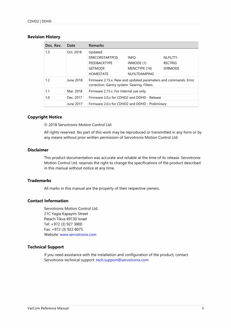
Revision History
Doc. Rev. Date Remarks
1.3 Oct. 2018 Updated:
ERRCORSTARTPOS
FEEDBACKTYPE
GETMODE
HOMESTATE
INFO
INMODE (1)
MENCTYPE (14)
NLFILTDAMPING
NLFILTT1
RECTRIG
SFBMODE
1.2 June 2018 Firmware 2.15.x. New and updated parameters and commands. Error
correction. Gantry system. Gearing. Filters.
1.1 Mar. 2018 Firmware 2.15.x. For Internal use only.
1.0 Dec. 2017 Firmware 2.0.x for CDHD2 and DDHD - Release
June 2017 Firmware 2.0.x for CDHD2 and DDHD - Preliminary
Copyright Notice
© 2018 Servotronix Motion Control Ltd.
All rights reserved. No part of this work may be reproduced or transmitted in any form or by
any means without prior written permission of Servotronix Motion Control Ltd.
Disclaimer
This product documentation was accurate and reliable at the time of its release. Servotronix
Motion Control Ltd. reserves the right to change the specifications of the product described
in this manual without notice at any time.
Trademarks
All marks in this manual are the property of their respective owners.
Contact Information
Servotronix Motion Control Ltd.
21C Yagia Kapayim Street
Petach Tikva 49130 Israel
Tel: +972 (3) 927 3800
Fax: +972 (3) 922 8075
Website: www.servotronix.com
Technical Support
If you need assistance with the installation and configuration of the product, contact
Servotronix technical support: [email protected]

CDHD2 | DDHD
4 VarCom Reference Manual

CDHD2 | DDHD
VarCom Reference Manual 5
Contents
1 Introduction VarCom Overview ......................................... 11 Manual Format ............................................... 11
2 VarCom Functions
Added/Finalized as of v.2.15.x ................. 13 Added as of v.2.0.x ....................................... 13 Activation and Faults ................................... 14 Hardware Power ............................................ 14 Communication ............................................. 14 Commutation ................................................. 15 Controller – Current ..................................... 15 Controller – Position .................................... 16 Controller – Velocity .................................... 16 Direction ........................................................... 16 Emergency Stop ............................................ 17 Error Correction ............................................. 17 Feedback .......................................................... 17 Feedback – Secondary ................................ 18 Foldback ........................................................... 18 Gantry ................................................................ 18 Gearing.............................................................. 18 HD Control – Anti-Vibration ..................... 19 HD Control – Basic Tuning ........................ 19 Homing ............................................................. 19 I/Os – Analog .................................................. 19 I/Os – Digital ................................................... 20 Limits .................................................................. 20 Linear System ................................................. 20 Memory – Non-volatile .............................. 20 Motion ............................................................... 21 Motor ................................................................. 21 Recording ......................................................... 21 Temperature ................................................... 22 Touch Probe .................................................... 22 Units ................................................................... 22
3 Variables and Commands ABCKUP ............................................................. 23 ACC ..................................................................... 24 ACTIVE ............................................................... 26 ADDR ................................................................. 27 ANIN1 ................................................................ 28 ANIN1DB .......................................................... 29 ANIN1FILTAFF ................................................ 30 ANIN1FILTIN ................................................... 31 ANIN1FILTMODE ........................................... 32 ANIN1FILTT1 ................................................... 33 ANIN1FILTT2 ................................................... 34
ANIN1FILTVELFF ............................................ 35 ANIN1ISCALE .................................................. 36 ANIN1LPFHZ ................................................... 37 ANIN1OFFSET ................................................ 38 ANIN1VSCALE ................................................ 39 ANIN1ZERO .................................................... 40 ANIN2 ................................................................ 41 ANIN2DB .......................................................... 42 ANIN2ISCALE .................................................. 43 ANIN2LPFHZ ................................................... 44 ANIN2MODE .................................................. 45 ANIN2OFFSET ................................................ 46 ANIN2USER ..................................................... 47 ANIN2USERDEN ............................................ 48 ANIN2USERNUM .......................................... 49 ANIN2USEROFFSET ...................................... 50 ANIN2ZERO .................................................... 51 ANOUT .............................................................. 52 ANOUTCMD ................................................... 53 ANOUTISCALE ................................................ 54 ANOUTLIM ...................................................... 55 ANOUTMODE................................................. 56 ANOUTVSCALE .............................................. 57 AQBFILT ............................................................ 58 AUTOHOME .................................................... 59 BAUDRATE ....................................................... 60 BISSCFIELDS .................................................... 61 BISSCINFO ....................................................... 63 BW ...................................................................... 64 CANBITRATE ................................................... 65 CANCONTROLWORD ................................. 66 CANSTATUSWORD ...................................... 67 CHECKSUM ..................................................... 68 CLEARFAULTS ................................................. 69 CLVD .................................................................. 70 CLVQ .................................................................. 71 COMMERRMAXCNT .................................... 72 COMMERRTTHRESH .................................... 73 COMMERRVTHRESH ................................... 74 COMMFLTTRESH .......................................... 75 COMMODE...................................................... 76 CONFIG ............................................................. 77 COUNTSINREV ............................................... 78 CUSTOMERID ................................................. 79 DEC ..................................................................... 80 DECSTOP .......................................................... 82 DECSTOPTIME ................................................ 83 DELAY ................................................................ 84 DICONT ............................................................. 85

CDHD2 | DDHD
6 VarCom Reference Manual
DIFPORTMODE .............................................. 86 DIPEAK .............................................................. 87 DIR ...................................................................... 88 DISMODE ......................................................... 89 DISPLAYMODE ............................................... 91 DISPLAYTEST ................................................... 92 DISSPEED .......................................................... 93 DISTIME ............................................................ 94 DRIVENAME .................................................... 95 DRIVESCRIPT ................................................... 96 DRIVESCRIPTDEL ........................................... 97 DRIVESCRIPTST .............................................. 98 DRIVETEMP ...................................................... 99 DUMP ..............................................................100 ECEMCYMODE .............................................101 ECHO ................................................................102 ECMAPDEFAULT ..........................................103 ECREADCOMMSTATE ................................104 ECSENDSDO ..................................................105 ECZEROMAP .................................................106 ELECTANGLE .................................................107 EN ......................................................................108 ENCFOLLOWER ............................................109 ENCOUTMODE .............................................111 ENCOUTRES ..................................................112 ENCOUTZPOS ...............................................113 ENDATERRWRN ...........................................114 ERRCORACTIVENUM .................................115 ERRCOREN .....................................................116 ERRCORFAILINDEX .....................................117 ERRCORINDEX ..............................................118 ERRCORINTERVAL ......................................119 ERRCORRESET ..............................................120 ERRCORSETINDEX ......................................121 ERRCORST ......................................................122 ERRCORSTARTOFF .....................................123 ERRCORSTARTPOS .....................................124 ERRCORUNITS ..............................................125 ESTOPILIM .....................................................126 EXTADDITIVEICMD .....................................127 EXTADDITIVEVCMD ...................................128 FACTORYRESTORE ......................................129 FASTSTOENABLE .........................................130 FBGDS ..............................................................131 FBGMS .............................................................132 FBINTTYPE ......................................................133 FBITIDX ............................................................134 FBITPRD ..........................................................135 FBPLIGNORE .................................................136 FBSCALE ..........................................................137 FBSYNCACT ...................................................138 FEEDBACKBR .................................................139
FEEDBACKTYPE ............................................ 140 FILTEXTHZ1 ................................................... 143 FILTEXTHZ2 ................................................... 144 FILTEXTMODE .............................................. 145 FILTHZ1 ........................................................... 146 FILTHZ2 ........................................................... 147 FILTMODE ...................................................... 148 FLT .................................................................... 149 FLTHIST ........................................................... 150 FOLD ................................................................ 151 FRICINEG ........................................................ 152 FRICIPOS ........................................................ 153 FRICNVHYST ................................................. 154 FRICPVHYST .................................................. 155 GANTRYALIGN ............................................. 156 GANTRYALIGNED ....................................... 157 GANTRYALIGNMODE ................................ 158 GANTRYCMDTYPE ...................................... 159 GANTRYCOMMSTATE ............................... 160 GANTRYDIFFICMD ..................................... 161 GANTRYDIFFPFB ......................................... 162 GANTRYDIFFVFB ......................................... 163 GANTRYFINDOFF ........................................ 164 GANTRYFINDOFFST ................................... 165 GANTRYINTERFACE ................................... 166 GANTRYMODE ............................................. 167 GANTRYMSTRICMD ................................... 168 GANTRYMSTRPFB ....................................... 169 GANTRYMSTRVFB ...................................... 170 GANTRYOFFSET ........................................... 171 GANTRYOFFSETST ...................................... 172 GANTRYPRTNRICMD ................................ 173 GANTRYPRTNRMFB ................................... 174 GANTRYPRTNRVFB .................................... 175 GANTRYTYPE ................................................ 176 GEAR ................................................................ 177 GEARACCTHRESH ....................................... 178 GEARDBVAL .................................................. 179 GEARFILTAFF ................................................ 180 GEARFILTDEPTH .......................................... 181 GEARFILTMODE ........................................... 182 GEARFILTT1 ................................................... 183 GEARFILTT2 ................................................... 184 GEARFILTVELFF ............................................ 185 GEARIN ........................................................... 186 GEARINMODE .............................................. 187 GEARLIMITSMODE ..................................... 188 GEARMODE ................................................... 190 GEAROUT ....................................................... 191 GET ................................................................... 192 GETMODE ...................................................... 193 GETREC ........................................................... 194

CDHD2 | DDHD
VarCom Reference Manual 7
HALLS ..............................................................195 HALLSCOMMTHRESH ...............................196 HALLSFILTAFF ...............................................197 HALLSFILTT1 .................................................198 HALLSFILTT2 .................................................199 HALLSFILTVELFF ..........................................200 HALLSINV .......................................................201 HALLSONLYCOMM ....................................202 HALLSTYPE .....................................................203 HOLD ...............................................................204 HOLDMODE ..................................................205 HOMEACC ......................................................207 HOMECMD ....................................................208 HOMECMDST ...............................................209 HOMEIHARDSTOP ......................................210 HOMEOFFSET ...............................................211 HOMEOFSTMOVE .......................................212 HOMESPEED1 ...............................................213 HOMESPEED2 ...............................................214 HOMESTATE ..................................................215 HOMETYPE ....................................................216 HSAVE ..............................................................220 HWPEXT ..........................................................221 HWPEXTCNTRLR .........................................222 HWPEXTMACHN .........................................223 HWPOS ...........................................................224 I ..........................................................................225 ICMD ................................................................226 ID .......................................................................227 IDENT ...............................................................228 IDENTOFF .......................................................230 IDENTST ..........................................................231 IFFLPFHZ .........................................................232 IFOLD ...............................................................233 IFOLDFTHRESH ............................................234 IFOLDWTHRESH ..........................................235 IGNOREBATTFLT ..........................................236 IGNOREBRKFLT ............................................237 IGNOREPDLB ................................................238 IGRAV...............................................................239 ILIM ...................................................................240 ILIMACT...........................................................241 IMAX ................................................................242 IN .......................................................................243 IN32OPMODES ............................................244 IN32SWITCH .................................................245 INDEXDURATE ..............................................246 INDEXPFB .......................................................247 INDEXST ..........................................................248 INFO .................................................................249 ININV ...............................................................250 INMODE ..........................................................252
INPOS .............................................................. 256 INPUTS ............................................................ 257 IQ ....................................................................... 258 ISTOP ............................................................... 259 IU ....................................................................... 260 IUOFFSET ........................................................ 261 IV ....................................................................... 262 IVOFFSET ........................................................ 263 IZERO ............................................................... 264 J .......................................................................... 265 JOGSPD1 ........................................................ 266 JOGSPD2 ........................................................ 267 K ......................................................................... 268 KCBEMF .......................................................... 269 KCD................................................................... 270 KCFF ................................................................. 271 KCI..................................................................... 272 KCMODE......................................................... 273 KCP ................................................................... 274 KCUSERGAIN ................................................ 275 KNLAFRC ........................................................ 276 KNLD ................................................................ 277 KNLDSOURCEMODE ................................. 278 KNLDUALLOOPAFF .................................... 279 KNLDUALLOOPKP ...................................... 280 KNLDUALLOOPVFF .................................... 281 KNLI .................................................................. 282 KNLIV ............................................................... 283 KNLP ................................................................ 284 KNLUSERGAIN ............................................. 285 KNLVFF ............................................................ 286 KPAFRC ........................................................... 287 KPAFRV ........................................................... 288 KPD ................................................................... 289 KPE .................................................................... 290 KPI ..................................................................... 291 KPISATIN ........................................................ 292 KPISATOUT .................................................... 293 KPP ................................................................... 294 KPPCHANGEMODE .................................... 295 KPVFR .............................................................. 296 KVFR ................................................................. 297 KVI..................................................................... 298 KVP ................................................................... 299 LIMSWITCHNEG .......................................... 300 LIMSWITCHPOS ........................................... 301 LINELOSSMODE .......................................... 302 LINELOSSRECOVER .................................... 303 LINELOSSTYPE .............................................. 304 LIST ................................................................... 305 LMJR................................................................. 306 LMJREST ......................................................... 307

CDHD2 | DDHD
8 VarCom Reference Manual
LMJRESTST .....................................................308 LMUNITSDEN ...............................................309 LMUNITSNUM ..............................................310 LOAD ................................................................311 MACC ...............................................................312 MB .....................................................................313 MBST ................................................................314 MDEC ...............................................................315 MECHANGLE .................................................316 MENCAQBFILT..............................................317 MENCRES .......................................................318 MENCTYPE .....................................................319 MENCZPOS ....................................................321 MFB...................................................................322 MFBDIR ...........................................................323 MFBMODE .....................................................325 MFOLD ............................................................326 MFOLDD .........................................................327 MFOLDDIS .....................................................328 MFOLDF ..........................................................329 MFOLDR .........................................................330 MFOLDT ..........................................................331 MICONT ..........................................................332 MIFOLD ...........................................................333 MIFOLDFTHRESH ........................................334 MIFOLDWTHRESH ......................................335 MIPEAK ............................................................336 MJ ......................................................................337 MKF ..................................................................338 MKT ..................................................................339 ML .....................................................................340 MLGAINC........................................................341 MLGAINP ........................................................342 MMASS ...........................................................343 MODMODE ...................................................344 MOTORCOMMTYPE ...................................345 MOTORNAME ..............................................346 MOTORSETUP ..............................................347 MOTORSETUPST .........................................349 MOTORTYPE .................................................350 MOVEABS .......................................................351 MOVEINC .......................................................352 MOVEINCCOUNTER ...................................353 MOVEINCDELAY ..........................................354 MOVEINCDIST1 ...........................................355 MOVEINCDIST2 ...........................................356 MOVEINCSPEED1 ........................................357 MOVEINCSPEED2 ........................................358 MOVESINE .....................................................359 MOVESMOOTHAVG ..................................360 MOVESMOOTHLPFHZ ..............................361 MOVESMOOTHMODE ..............................362
MOVESMOOTHSRC ................................... 363 MPHASE ......................................................... 364 MPITCH ........................................................... 365 MPOLES .......................................................... 366 MR .................................................................... 367 MRESPOLES................................................... 368 MSGPROMPT ............................................... 369 MSININT ......................................................... 370 MSPEED .......................................................... 371 MTANGLC ...................................................... 372 MTANGLP ...................................................... 373 MTPMODE ..................................................... 374 MTPST ............................................................. 375 MTTURNRESET............................................. 376 MVANGLF ...................................................... 377 MVANGLH ..................................................... 378 MVEL ................................................................ 379 NLAFFLPFHZ ................................................. 380 NLANTIVIBGAIN .......................................... 381 NLANTIVIBGAIN2 ....................................... 382 NLANTIVIBGAIN3 ....................................... 383 NLANTIVIBHZ ............................................... 384 NLANTIVIBHZ2 ............................................ 385 NLANTIVIBHZ3 ............................................ 386 NLANTIVIBLMJR .......................................... 387 NLANTIVIBN ................................................. 388 NLANTIVIBQ3 ............................................... 389 NLANTIVIBSHARP ....................................... 390 NLANTIVIBSHARP2 .................................... 391 NLANTIVIBSHARP3 .................................... 392 NLFILTDAMPING ......................................... 393 NLFILTMODE ................................................ 395 NLFILTMODE2 .............................................. 396 NLFILTT1 ......................................................... 397 NLMAXGAIN ................................................. 399 NLNOTCH2BW ............................................. 400 NLNOTCH2CENTER ................................... 401 NLNOTCHBW ............................................... 402 NLNOTCHCENTER ...................................... 403 NLPEAFF ......................................................... 404 NLPEDFFRATIO ............................................ 405 NLTFBW .......................................................... 406 NLTFDESIGNMODE .................................... 407 NLVELLIM ....................................................... 408 OPMODE ........................................................ 409 OPMODESWITCH ....................................... 410 OUT .................................................................. 412 OUTBRAKE ..................................................... 413 OUTBRAKEINV ............................................. 414 OUTBRAKEMODE........................................ 415 OUTFLTLVL .................................................... 416 OUTILVL1 ....................................................... 418

CDHD2 | DDHD
VarCom Reference Manual 9
OUTILVL2........................................................419 OUTINV ...........................................................420 OUTMODE .....................................................421 OUTPLVL1 ......................................................423 OUTPLVL2 ......................................................424 OUTPUTS ........................................................425 OUTVLVL1 ......................................................426 OUTVLVL2 ......................................................427 OVTHRESH .....................................................428 PASSWORD ...................................................429 PATHACC ........................................................430 PATHCTRL ......................................................431 PATHDEC ........................................................433 PATHDELAY ...................................................434 PATHPOS ........................................................435 PATHSPEED ...................................................437 PCMD ...............................................................438 PCMDFBRAW ................................................439 PCMDRAW .....................................................440 PCOMCNTRL1 ..............................................441 PCOMCNTRL2 ..............................................442 PCOMDIR1 .....................................................443 PCOMDIR2 .....................................................444 PCOMEND1 ...................................................445 PCOMEND2 ...................................................446 PCOMN1.........................................................447 PCOMN2.........................................................449 PCOMSTART1 ...............................................450 PCOMSTART2 ...............................................451 PCOMSTATUS1 ............................................452 PCOMSTATUS2 ............................................453 PCOMTABLE1 ...............................................454 PCOMTABLE2 ...............................................456 PCOMTABLELEN1 .......................................457 PCOMTABLELEN2 .......................................458 PCOMWIDTH1 .............................................459 PCOMWIDTH2 .............................................460 PDEN ................................................................461 PE .......................................................................462 PEDELAYED ....................................................463 PEDELAYTIME ...............................................464 PEINPOS .........................................................465 PEINPOSTIME ...............................................466 PELOOP ...........................................................467 PEMAX .............................................................468 PFB ....................................................................469 PFBBACKUP ...................................................470 PFBBACKUPMODE ......................................471 PFBOFFSET .....................................................472 PFBRAW ..........................................................473 PHASEFIND ....................................................474 PHASEFINDANGLE ......................................475
PHASEFINDDELTA ...................................... 476 PHASEFINDGAIN ......................................... 477 PHASEFINDI .................................................. 478 PHASEFINDMODE ...................................... 479 PHASEFINDST............................................... 482 PHASEFINDTIME ......................................... 483 PNUM .............................................................. 484 POSCONTROLMODE ................................. 485 POSLIMHYST ................................................ 486 POSLIMMODE .............................................. 487 POSLIMNEG .................................................. 490 POSLIMPOS ................................................... 491 PRBFRQ ........................................................... 492 PRBHOLD ....................................................... 493 PRBICMD ........................................................ 494 PRBMODE ...................................................... 495 PRBPARAM .................................................... 496 PROBECONFIG ............................................. 497 PROBECOUNTER ......................................... 499 PROBEDATAFALL ........................................ 500 PROBEDATARISE ......................................... 501 PROBELEVELFLT ........................................... 502 PROBELEVELPRD ......................................... 503 PROBESTATUS.............................................. 504 PROTARY ........................................................ 506 PTPTE ............................................................... 507 PTPVCMD....................................................... 508 PWMFRQ ........................................................ 509 READY ............................................................. 510 RECDONE ....................................................... 511 RECING ........................................................... 512 RECLIST ........................................................... 513 RECOFF ........................................................... 514 RECORD .......................................................... 515 RECRDY ........................................................... 516 RECTRIG .......................................................... 517 RECTRIGLIST ................................................. 519 REFOFFSETVAL ............................................. 520 REGENFLTMODE ......................................... 521 REGENMAXONTIME .................................. 522 REGENMAXPOW ......................................... 523 REGENPOW ................................................... 524 REGENRES ...................................................... 525 RELAY .............................................................. 526 RELAYMODE ................................................. 527 REMOTE .......................................................... 528 RESAMPLRANGE ......................................... 529 RESBW ............................................................. 530 RESFILTMODE .............................................. 531 SAVE ................................................................. 532 SFB .................................................................... 533 SFBACC ........................................................... 534
CDHD2 | DDHD
10 VarCom Reference Manual
SFBDEC ............................................................535 SFBDIR .............................................................536 SFBENCTYPE ..................................................537 SFBMODE .......................................................538 SFBOFFSET .....................................................540 SFBRES .............................................................541 SFBTYPE ..........................................................542 SFBVCMD .......................................................543 SFBVEL .............................................................544 SFBVLIM ..........................................................545 SININIT ............................................................546 SININITMODE ...............................................547 SININITST .......................................................548 SINPARAM .....................................................549 SKTEMPVOLT ................................................550 SKTURNRESET ..............................................551 SRVSNSINFO .................................................552 ST .......................................................................554 STALLTIME .....................................................555 STALLVEL ........................................................556 STAT .................................................................557 STATUS ............................................................558 STEP ..................................................................559 STOP .................................................................560 STOPDIST .......................................................561 STOPPED ........................................................562 STOPPEDDURATE .......................................563 SWEN ...............................................................564 SWENMODE ..................................................565 SYNCSOURCE ...............................................566 T .........................................................................567 TF .......................................................................568 THERM .............................................................569 THERMCLEARLEVEL....................................570 THERMODE....................................................571 THERMREADOUT ........................................572 THERMTIME ..................................................573 THERMTRIPLEVEL ........................................574 THERMTYPE ...................................................575 TMTEMP .........................................................576 TMTURNRESET .............................................577 TRUN ................................................................578 UNITSLINACC ...............................................579 UNITSLINPOS ...............................................580 UNITSLINVEL.................................................581 UNITSROTACC .............................................582 UNITSROTPOS ..............................................583
UNITSROTVEL .............................................. 584 USERPARAM ................................................. 585 UVMODE ........................................................ 586 UVRECOVER .................................................. 587 UVTHRESH ..................................................... 588 UVTIME ........................................................... 589 V ........................................................................ 590 VBUS ................................................................ 591 VBUSREADOUT ............................................ 592 VCMD .............................................................. 593 VD ..................................................................... 594 VE ...................................................................... 595 VELCMDMOVEAVG .................................... 596 VELCONTROLMODE .................................. 597 VELCONTROLOUT ...................................... 598 VELDESIGN .................................................... 599 VELFILTFRQ ................................................... 600 VELFILTMODE ............................................... 601 VEMAX ............................................................ 602 VER ................................................................... 603 VF ...................................................................... 604 VFEXT ............................................................... 605 VFI ..................................................................... 606 VG ..................................................................... 607 VH ..................................................................... 608 VINT ................................................................. 609 VLIM ................................................................. 610 VMAX............................................................... 611 VR ...................................................................... 612 WNSERR ......................................................... 613 WRN ................................................................. 614 XENCRES ........................................................ 615 ZERO ................................................................ 616 ZEROST ........................................................... 617
4 Serial Communication Serial Communication Overview .......... 618 Data Transmission Format ...................... 619 Drive Addressing......................................... 619 Daisy-Chain (Multi-Drop) Configuration 619 Serial Variables and Commands ........... 620 Data Control ................................................. 620 Message Format.......................................... 621 Asynchronous Error Messages .............. 623 Examples of Serial Protocol .................... 623
CDHD2 | DDHD Introduction
VarCom Reference Manual 11
1 Introduction
VarCom Overview
When the host and drive are communicating over serial connection, a proprietary set of
commands and variables, called VarCom, are used to configure, control and monitor the
drive.
Commands and variables are identified by mnemonic (easily remembered code) names. For
example, MPOLES is the VarCom code used to read and write the setting for the number of
motor poles.
Some variables are read-only, while others have read and write access. Variables can be
stored in the CDHD2’s non-volatile flash memory for use at each power-up.
Note The terms variable and parameter are used interchangeably throughout the
documentation.
Manual Format
This manual details the entire set of VarCom commands and variables, in alphabetic order.
Command and variable descriptions use different formats, as described below.
All commands and variables are presented as follows:
Definition Short name, used in the graphical user interface software.
Type Variable (R/W): A read/write variable.
Variable (R): A read-only variable.
Command
Description Description of the command or variable.
Syntax The command format, including any optional or required arguments.
Commands are described using the following conventions:
[ ] Indicates an optional argument.
{ } Indicates a required argument.
| A vertical bar separates two or more choices, either required
arguments enclosed in braces { } or optional arguments enclosed
in brackets [ ].
Variable arguments are italicized within < >.
Firmware The earliest version, or specific versions, in which the described
functionality is available.
Drive status Enabled | Disabled
Indicates the required state of the drive when the command or variable
is issued or invoked.

Introduction CDHD2 | DDHD
12 VarCom Reference Manual
Range Discrete values and ranges of values.
Parameter values can be written with up to 9 digits following the
decimal point. When read, values will show only 3 digits following the
decimal point.
For example:
-->acc 0.123456789
-->acc
0.123 [rpm/s]
-->
Default value The variable’s default (factory-defined) value.
Unit When variable or command values imply units of measure, these units
are specified.
Non-volatile Yes | No
Indicates whether the value of the variable is stored in the non-volatile
memory, and thereby available when the drive is rebooted.
Not applicable for Command.
Example Examples of use.
Related Links to related commands and variables.
EtherCAT
CANopen
Where applicable, the equivalent EtherCAT COE and CANopen object
code.

CDHD2 | DDHD VarCom Functions
VarCom Reference Manual 13
2 VarCom Functions
Added/Finalized as of v.2.15.x
Variable and commands added to the firmware and/or documentation as of Version 2.15.x
ABCKUP
COUNTSINREV
ENDATERRWRN
ERRCORACTIVENUM
ERRCOREN
ERRCORFAILINDEX
ERRCORINDEX
ERRCORINTERVAL
ERRCORRESET
ERRCORSETINDEX
ERRCORST
ERRCORSTARTOFF
ERRCORSTARTPOS
ERRCORUNITS
FILTEXTHZ1
FILTEXTHZ2
FILTEXTMODE
GANTRYALIGN
GANTRYALIGNED
GANTRYALIGNMODE
GANTRYCMDTYPE
GANTRYCOMMSTATE
GANTRYDIFFICMD
GANTRYDIFFPFB
GANTRYDIFFVFB
GANTRYFINDOFF
GANTRYFINDOFFST
GANTRYINTERFACE
GANTRYMODE
GANTRYMSTRICMD
GANTRYMSTRPFB
GANTRYMSTRVFB
GANTRYOFFSET
GANTRYOFFSETST
GANTRYPRTNRICMD
GANTRYPRTNRMFB
GANTRYPRTNRVFB
GANTRYTYPE
IDENT
IDENTOFF
IDENTST
NLFILTMODE
NLFILTMODE2
PFBRAW
VFEXT
Added as of v.2.0.x
Variable and commands added to the firmware and/or documentation as of Version 2.0.x
AQBFILT
CANCONTROLWORD
CANSTATUSWORD
DIFPORTMODE
DRIVESCRIPTDEL
ECMAPDEFAULT
ECSENDSDO
ECZEROMAP
FBINTTYPE
FBSYNCACT
GEARFILTDEPTH
KNLDSOURCEMODE
KNLDUALLOOPAFF
KNLDUALLOOPKP
KNLDUALLOOPVFF
KPPCHANGEMODE
LMJREST
LMJRESTST
LMUNITSDEN
LMUNITSNUM
MACC
MDEC
MFB
MVEL
NLTFBW
NLTFDESIGNMODE
PCOMCNTRL1
PCOMCNTRL2
PCOMDIR1
PCOMDIR2
PCOMEND1
PCOMEND2
PCOMN1
PCOMN2
PCOMSTART1
PCOMSTART2
PCOMSTATUS1
PCOMSTATUS2
PCOMTABLE1
PCOMTABLE2
PCOMTABLELEN1
PCOMTABLELEN2
PCOMWIDTH1
PCOMWIDTH2
PEDELAYED
PEDELAYTIME
PRBHOLD
PRBICMD
PROBELEVELFLT
SFBACC
SFBDEC
SFBDIR
SFBENCTYPE
SFBMODE
SFBRES
SFBTYPE
SFBVEL
SFBVCMD
SFBVLIM
STOPDIST
USERPARAM
VG
VINT

VarCom Functions CDHD2 | DDHD
14 VarCom Reference Manual
Activation and Faults
Includes drive status, software enable, hardware enable, faults, fault history, fault recovery,
clear faults, emergency stop.
ACTIVE
CLEARFAULTS
DISMODE
DISPLAYTEST
EN
FASTSTOENABLE
FLT
FLTHIST
K
COMMERRMAXCNT
COMMERRTTHRESH
COMMERRVTHRESH
IGNOREBRKFLT
OUTFLTLVL
READY
RELAY
RELAYMODE
REMOTE
ST
STALLTIME
STALLVEL
STAT
STATUS
SWEN
SWENMODE
UVMODE
UVRECOVER
UVTHRESH
UVTIME
WRN
Hardware Power
Includes bus, PWM, drive rating, regeneration resistor, line-loss, under-voltage.
DICONT
DIPEAK
KCD
LINELOSSMODE
LINELOSSRECOVER
LINELOSSTYPE
OVTHRESH
PWMFRQ
REGENFLTMODE
REGENMAXONTIME
REGENMAXPOW
REGENPOW
REGENRES
UVMODE
UVRECOVER
UVTHRESH
UVTIME
VBUS
VBUSREADOUT
Communication
Includes drive address, serial communication, fieldbus, peek-poke, privilege.
ABCKUP
ADDR
BAUDRATE
CHECKSUM
COMMODE
DELAY
DRIVESCRIPT
DRIVESCRIPTDEL
DRIVESCRIPTST
ECEMCYMODE
ECHO
ECMAPDEFAULT
ECZEROMAP
ECREADCOMMSTATE
ECSENDSDO
FBGDS
FBGMS
FBINTTYPE
FBITIDX
FBITPRD
FBGDS
FBGMS
FBITIDX
FBITPRD
FBPLIGNORE
FBSCALE
FBSYNCACT
GETMODE
MSGPROMPT
MTPMODE
OPMODE
PASSWORD
SYNCSOURCE

CDHD2 | DDHD VarCom Functions
VarCom Reference Manual 15
Commutation
Includes phase find, phase advance, electrical angle, Hall sensors, sine commutation, six-step.
CANBITRATE
CANCONTROLWORD
CANSTATUSWORD
COMMERRMAXCNT
COMMERRTTHRESH
COMMERRVTHRESH
COMMFLTTRESH
COMMFLTTRESH
CONFIG
DIFPORTMODE
ELECTANGLE
FEEDBACKTYPE
GETREC
HALLS
HALLSINV
HALLSTYPE
MENCRES
MENCTYPE
MENCZPOS
MOTORCOMMTYPE
MOTORSETUP
MOTORSETUPST
MPHASE
MPITCH
MPOLES
MTANGLC
MTANGLP
MVANGLF
MVANGLH
PHASEFIND
PHASEFINDANGLE
PHASEFINDDELTA
PHASEFINDGAIN
PHASEFINDI
PHASEFINDMODE
PHASEFINDST
PHASEFINDTIME
WNSERR
ZERO
ZEROST
Controller – Current
Includes controller, variables, DQ coordinates, phasing.
ANIN1ISCALE
ANIN2ISCALE
CLVD
CLVQ
CONFIG
ESTOPILIM
FRICINEG
FRICIPOS
FRICNVHYST
FRICPVHYST
I
ICMD
I
ID
IFFLPFHZ
IGRAV
ILIM
IMAX
IQ
IU
IUOFFSET
IV
IVOFFSET
KCBEMF
KCD
KCFF
KCI
KCMODE
KCP
MICONT
MIPEAK
ML
MLGAINC
MLGAINP
OPMODE
OUTILVL1
OUTILVL2
STOP
T
VBUS

VarCom Functions CDHD2 | DDHD
16 VarCom Reference Manual
Controller – Position
Includes controller, variables, gains.
DIR
FRICINEG
FRICIPOS
FRICNVHYST
FRICPVHYST
GEARIN
GEARMODE
GEAROUT
HOLD
HWPEXT
HWPEXTCNTRLR
HWPEXTMACHN
HWPOS
ICMD
INPOS
KNLVFF
KPAFRC
KPAFRV
KPD
KPE
KPI
KPISATIN
KPISATOUT
KPP
KPPCHANGEMODE
KPVFR
MECHANGLE
MFBDIR
MODMODE
MOVEABS
MOVEINC
OPMODE
OUTPLVL1
OUTPLVL2
PCMD
PCMDFBRAW
PE
PEDELAYED
PEDELAYTIME
PEINPOS
PEINPOSTIME
PELOOP
PEMAX
PFB
POSCONTROLMODE
PROTARY
PTPTE
PTPVCMD
STOP
STOPDIST
STOPPED
UNITSLINPOS
UNITSROTPOS
VCMD
Controller – Velocity
Includes controller, variables, gains.
ANIN1VSCALE
BW
FILTHZ1
FILTHZ2
FILTEXTHZ1
FILTEXTHZ2
FILTEXTMODE
FILTMODE
FRICINEG
FRICIPOS
FRICNVHYST
FRICPVHYST
ICMD
J
KVFR
KVI
KVP
LMJR
LMJREST
LMJRESTST
MJ
MKT
MSPEED
NLVELLIMOPMODE
OUTVLVL1
OUTVLVL2
STEP
STOP
TF
UNITSLINVEL
UNITSROTVEL
V
VCMD
VD
VE
VELCONTROLMODE
VELDESIGN
VELFILTFRQ
VELFILTMODE
VF
VFEXT
VG
VFI
VH
VLIM
VMAX
VR
Direction
Includes elements and procedures related to direction of elements and motion, such as
feedback device, motor leads, Halls.
DIR
ELECTANGLE
HWPOS
MECHANGLE
MFBDIR
MOTORSETUP
MOTORSETUPST
MPHASE
PFB
V
CDHD2 | DDHD VarCom Functions
VarCom Reference Manual 17
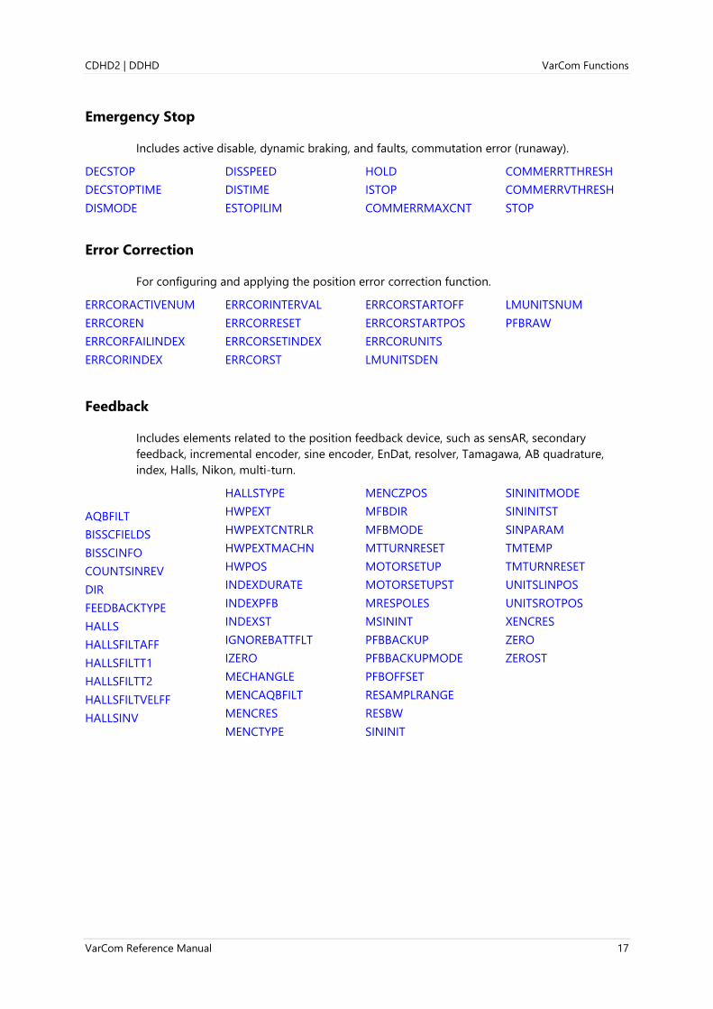
Emergency Stop
Includes active disable, dynamic braking, and faults, commutation error (runaway).
DECSTOP
DECSTOPTIME
DISMODE
DISSPEED
DISTIME
ESTOPILIM
HOLD
ISTOP
COMMERRMAXCNT
COMMERRTTHRESH
COMMERRVTHRESH
STOP
Error Correction
For configuring and applying the position error correction function.
ERRCORACTIVENUM
ERRCOREN
ERRCORFAILINDEX
ERRCORINDEX
ERRCORINTERVAL
ERRCORRESET
ERRCORSETINDEX
ERRCORST
ERRCORSTARTOFF
ERRCORSTARTPOS
ERRCORUNITS
LMUNITSDEN
LMUNITSNUM
PFBRAW
Feedback
Includes elements related to the position feedback device, such as sensAR, secondary
feedback, incremental encoder, sine encoder, EnDat, resolver, Tamagawa, AB quadrature,
index, Halls, Nikon, multi-turn.
AQBFILT
BISSCFIELDS
BISSCINFO
COUNTSINREV
DIR
FEEDBACKTYPE
HALLS
HALLSFILTAFF
HALLSFILTT1
HALLSFILTT2
HALLSFILTVELFF
HALLSINV
HALLSTYPE
HWPEXT
HWPEXTCNTRLR
HWPEXTMACHN
HWPOS
INDEXDURATE
INDEXPFB
INDEXST
IGNOREBATTFLT
IZERO
MECHANGLE
MENCAQBFILT
MENCRES
MENCTYPE
MENCZPOS
MFBDIR
MFBMODE
MTTURNRESET
MOTORSETUP
MOTORSETUPST
MRESPOLES
MSININT
PFBBACKUP
PFBBACKUPMODE
PFBOFFSET
RESAMPLRANGE
RESBW
SININIT
SININITMODE
SININITST
SINPARAM
TMTEMP
TMTURNRESET
UNITSLINPOS
UNITSROTPOS
XENCRES
ZERO
ZEROST
VarCom Functions CDHD2 | DDHD
18 VarCom Reference Manual
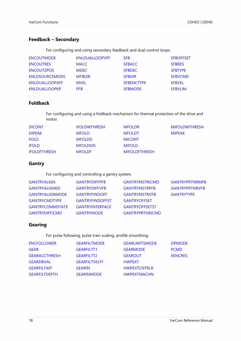
Feedback – Secondary
For configuring and using secondary feedback and dual control loops.
ENCOUTMODE
ENCOUTRES
ENCOUTZPOS
KNLDSOURCEMODE
KNLDUALLOOPAFF
KNLDUALLOOPKP
KNLDUALLOOPVFF
MACC
MDEC
MFBDIR
MVEL
PFB
SFB
SFBACC
SFBDEC
SFBDIR
SFBENCTYPE
SFBMODE
SFBOFFSET
SFBRES
SFBTYPE
SFBVCMD
SFBVEL
SFBVLIM
Foldback
For configuring and using a foldback mechanism for thermal protection of the drive and
motor.
DICONT
DIPEAK
FOLD
IFOLD
IFOLDFTHRESH
IFOLDWTHRESH
MFOLD
MFOLDD
MFOLDDIS
MFOLDF
MFOLDR
MFOLDT
MICONT
MIFOLD
MIFOLDFTHRESH
MIFOLDWTHRESH
MIPEAK
Gantry
For configuring and controlling a gantry system.
GANTRYALIGN
GANTRYALIGNED
GANTRYALIGNMODE
GANTRYCMDTYPE
GANTRYCOMMSTATE
GANTRYDIFFICMD
GANTRYDIFFPFB
GANTRYDIFFVFB
GANTRYFINDOFF
GANTRYFINDOFFST
GANTRYINTERFACE
GANTRYMODE
GANTRYMSTRICMD
GANTRYMSTRPFB
GANTRYMSTRVFB
GANTRYOFFSET
GANTRYOFFSETST
GANTRYPRTNRICMD
GANTRYPRTNRMFB
GANTRYPRTNRVFB
GANTRYTYPE
Gearing
For pulse following, pulse train scaling, profile smoothing.
ENCFOLLOWER
GEAR
GEARACCTHRESH
GEARDBVAL
GEARFILTAFF
GEARFILTDEPTH
GEARFILTMODE
GEARFILTT1
GEARFILTT2
GEARFILTVELFF
GEARIN
GEARINMODE
GEARLIMITSMODE
GEARMODE
GEAROUT
HWPEXT
HWPEXTCNTRLR
HWPEXTMACHN
OPMODE
PCMD
XENCRES
CDHD2 | DDHD VarCom Functions
VarCom Reference Manual 19
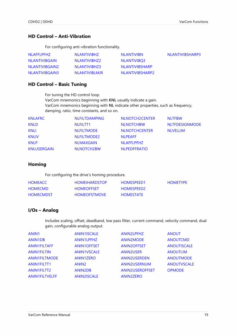
HD Control – Anti-Vibration
For configuring anti-vibration functionality.
NLAFFLPFHZ
NLANTIVIBGAIN
NLANTIVIBGAIN2
NLANTIVIBGAIN3
NLANTIVIBHZ
NLANTIVIBHZ2
NLANTIVIBHZ3
NLANTIVIBLMJR
NLANTIVIBN
NLANTIVIBQ3
NLANTIVIBSHARP
NLANTIVIBSHARP2
NLANTIVIBSHARP3
HD Control – Basic Tuning
For tuning the HD control loop.
VarCom mnemonics beginning with KNL usually indicate a gain.
VarCom mnemonics beginning with NL indicate other properties, such as frequency,
damping, ratio, time constants, and so on.
KNLAFRC
KNLD
KNLI
KNLIV
KNLP
KNLUSERGAIN
NLFILTDAMPING
NLFILTT1
NLFILTMODE
NLFILTMODE2
NLMAXGAIN
NLNOTCH2BW
NLNOTCH2CENTER
NLNOTCHBW
NLNOTCHCENTER
NLPEAFF
NLAFFLPFHZ
NLPEDFFRATIO
NLTFBW
NLTFDESIGNMODE
NLVELLIM
Homing
For configuring the drive’s homing procedure.
HOMEACC
HOMECMD
HOMECMDST
HOMEIHARDSTOP
HOMEOFFSET
HOMEOFSTMOVE
HOMESPEED1
HOMESPEED2
HOMESTATE
HOMETYPE
I/Os – Analog
Includes scaling, offset, deadband, low pass filter, current command, velocity command, dual
gain, configurable analog output.
ANIN1
ANIN1DB
ANIN1FILTAFF
ANIN1FILTIN
ANIN1FILTMODE
ANIN1FILTT1
ANIN1FILTT2
ANIN1FILTVELFF
ANIN1ISCALE
ANIN1LPFHZ
ANIN1OFFSET
ANIN1VSCALE
ANIN1ZERO
ANIN2
ANIN2DB
ANIN2ISCALE
ANIN2LPFHZ
ANIN2MODE
ANIN2OFFSET
ANIN2USER
ANIN2USERDEN
ANIN2USERNUM
ANIN2USEROFFSET
ANIN2ZERO
ANOUT
ANOUTCMD
ANOUTISCALE
ANOUTLIM
ANOUTMODE
ANOUTVSCALE
OPMODE

VarCom Functions CDHD2 | DDHD
20 VarCom Reference Manual
I/Os – Digital
Includes encoder simulation, limit switch, homing, clear fault, active state, brake, in position,
stopped, polarity inversion, drive script.
ENCOUTMODE
ENCOUTRES
ENCOUTZPOS
GEARIN
GEARMODE
GEAROUT
HWPEXT
HWPEXTCNTRLR
HWPEXTMACHN
IN
IN32OPMODES
IN32SWITCH
ININV
INMODE
INPUTS
JOGSPD1
JOGSPD2
OUT
OUTBRAKE
OUTBRAKEINV
OUTBRAKEMODE
OUTFLTLVL
OUTILVL1
OUTILVL2
OUTINV
OUTMODE
OUTPLVL1
OUTPLVL2
OUTPUTS
OUTVLVL1
OUTVLVL2
PCOMCNTRL1
PCOMCNTRL2
PCOMDIR1
PCOMDIR2
PCOMEND1
PCOMEND2
PCOMN1
PCOMN2
PCOMSTART1
PCOMSTART2
PCOMSTATUS1
PCOMSTATUS2
PCOMTABLE1
PCOMTABLE2
PCOMTABLELEN1
PCOMTABLELEN2
PCOMWIDTH1
PCOMWIDTH2
RELAY
RELAYMODE
SYNCSOURCE
XENCRES
Limits
Includes current, velocity, position, soft limits, stall detection, foldback.
DICONT
DIPEAK
ESTOPILIM
FOLD
HOMEIHARDSTOP
IFOLD
ILIM
ILIMACT
IMAX
LIMSWITCHNEG
LIMSWITCHPOS
MFOLD
MFOLDDIS
MICONT
MIFOLD
MIPEAK
MSPEED
POSLIMHYST
POSLIMMODE
POSLIMNEG
POSLIMPOS
STALLTIME
STALLVEL
VLIM
VMAX
Linear System
Includes support for linear motor units, pitch, mass, force.
MKF
MMASS
MOTORTYPE
MPITCH
UNITSLINACC
UNITSLINPOS
UNITSLINVEL
Memory – Non-volatile
Includes non-volatile memory elements, low level dump, non-SSV parameters that are saved,
position backup process, firmware upgrade, production key, factory restore.
DICONT
DIPEAK
DUMP
FACTORYRESTORE
LOAD
OVTHRESH
PFBBACKUP
PFBBACKUPMODE
SAVE
UVTHRESH

CDHD2 | DDHD VarCom Functions
VarCom Reference Manual 21
Motion
Includes command profile source, trapeze, S-curve, profile smoothing, serial motion
commands, user selectable units, acceleration, deceleration.
ACC
DEC
DECSTOP
HOLD
HOLDMODE
IN32OPMODES
IN32SWITCH
J
JOGSPD1
JOGSPD2
MB
MBST
MODMODE
MOVEABS
MOVEINC
MOVEINCCOUNTER
MOVEINCDELAY
MOVEINCDIST1
MOVEINCDIST2
MOVEINCSPEED1
MOVEINCSPEED2
MOVESINE
MOVESMOOTHAVG
MOVESMOOTHLPFHZ
MOVESMOOTHMODE
MOVESMOOTHSRC
PDEN
PEINPOSTIME
PNUM
PROTARY
PTPTE
PTPVCMD
STEP
STOPPED
UNITSLINACC
UNITSLINPOS
UNITSLINVEL
UNITSROTACC
UNITSROTPOS
UNITSROTVEL
VELCMDMOVEAVG
VLIM
Motor
Includes motor configuration parameters, type of motor, type of feedback, type of encoder,
directions, thermal switch, phase advance, adaptive gain, foldback readout, temperature
readout, motor setup procedure, motor parameter estimation.
DIR
FEEDBACKTYPE
MENCRES
MENCTYPE
MENCZPOS
MFBDIR
MFOLD
MFOLDD
MFOLDDIS
MFOLDF
MFOLDR
MFOLDT
MICONT
MIFOLD
MIFOLDFTHRESH
MIFOLDWTHRESH
MIPEAK
MJ
MKF
MKT
ML
MLGAINC
MLGAINP
MMASS
MOTORCOMMTYPE
MOTORNAME
MOTORSETUP
MOTORSETUPST
MOTORTYPE
MPHASE
MPITCH
MPOLES
MR
MRESPOLES
MSPEED
MTANGLC
MTANGLP
MTPMODE
MVANGLF
MVANGLH
OUTBRAKE
OUTBRAKEINV
OUTBRAKEMODE
THERM
THERMCLEARLEVEL
THERMODE
THERMREADOUT
THERMTIME
THERMTRIPLEVEL
THERMTYPE
Recording
Includes captured signals for analysis, triggering, variables, timing, data retrieval.
GET
GETMODE
IDENT
IDENTOFF
IDENTST
PRBFRQ
PRBHOLD
PRBICMD
PRBMODE
PRBPARAM
RECDONE
RECING
RECLIST
RECOFF
RECORD
RECRDY
RECTRIG
RECTRIGLIST
VarCom Functions CDHD2 | DDHD
22 VarCom Reference Manual
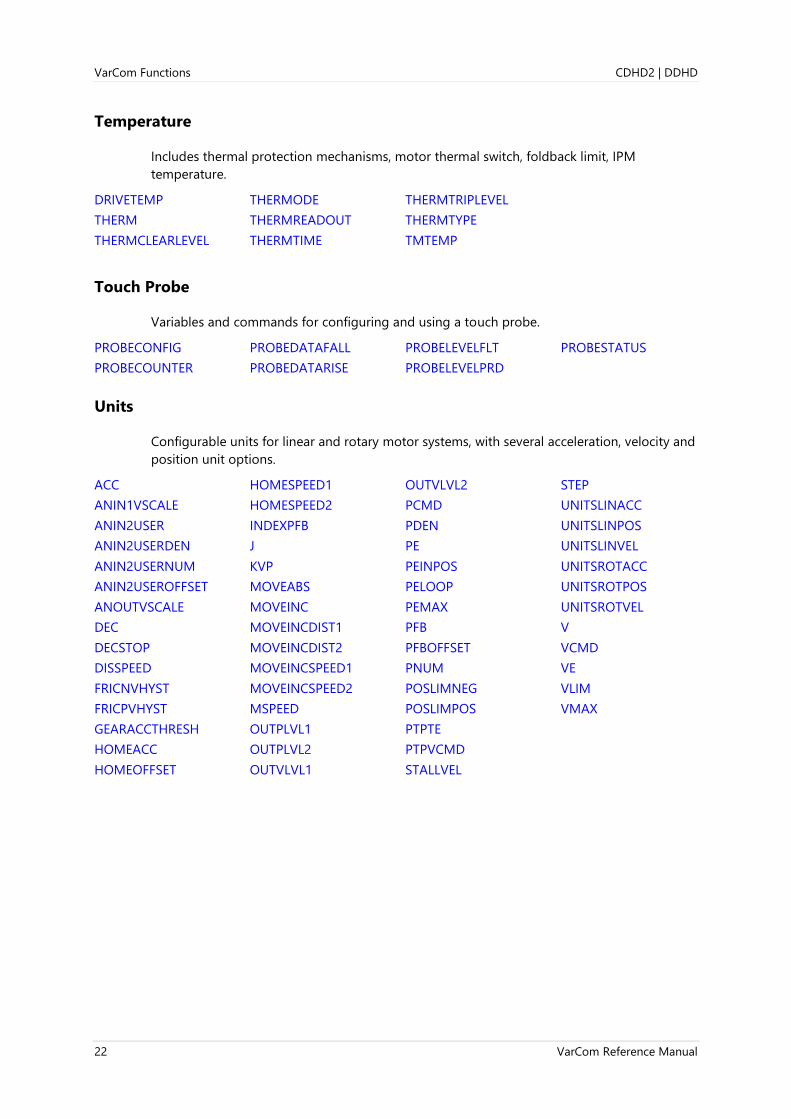
Temperature
Includes thermal protection mechanisms, motor thermal switch, foldback limit, IPM
temperature.
DRIVETEMP
THERM
THERMCLEARLEVEL
THERMODE
THERMREADOUT
THERMTIME
THERMTRIPLEVEL
THERMTYPE
TMTEMP
Touch Probe
Variables and commands for configuring and using a touch probe.
PROBECONFIG
PROBECOUNTER
PROBEDATAFALL
PROBEDATARISE
PROBELEVELFLT
PROBELEVELPRD
PROBESTATUS
Units
Configurable units for linear and rotary motor systems, with several acceleration, velocity and
position unit options.
ACC
ANIN1VSCALE
ANIN2USER
ANIN2USERDEN
ANIN2USERNUM
ANIN2USEROFFSET
ANOUTVSCALE
DEC
DECSTOP
DISSPEED
FRICNVHYST
FRICPVHYST
GEARACCTHRESH
HOMEACC
HOMEOFFSET
HOMESPEED1
HOMESPEED2
INDEXPFB
J
KVP
MOVEABS
MOVEINC
MOVEINCDIST1
MOVEINCDIST2
MOVEINCSPEED1
MOVEINCSPEED2
MSPEED
OUTPLVL1
OUTPLVL2
OUTVLVL1
OUTVLVL2
PCMD
PDEN
PE
PEINPOS
PELOOP
PEMAX
PFB
PFBOFFSET
PNUM
POSLIMNEG
POSLIMPOS
PTPTE
PTPVCMD
STALLVEL
STEP
UNITSLINACC
UNITSLINPOS
UNITSLINVEL
UNITSROTACC
UNITSROTPOS
UNITSROTVEL
V
VCMD
VE
VLIM
VMAX
CDHD2 | DDHD Variables and Commands
VarCom Reference Manual 23
3 Variables and Commands
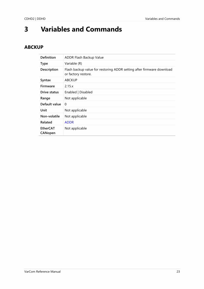
ABCKUP
Definition ADDR Flash Backup Value
Type Variable (R)
Description Flash backup value for restoring ADDR setting after firmware download
or factory restore.
Syntax ABCKUP
Firmware 2.15.x
Drive status Enabled | Disabled
Range Not applicable
Default value 0
Unit Not applicable
Non-volatile Not applicable
Related ADDR
EtherCAT
CANopen
Not applicable

Variables and Commands CDHD2 | DDHD
24 VarCom Reference Manual
ACC
Definition Acceleration
Type Variable (R/W)
Description Gets/sets the acceleration value of the motor (in motor feedback units) or
the load (in secondary feedback units), according to SFBMODE.
MACC and SFBACC mirror the value of ACC in order to maintain the
correct value of motor feedback or load feedback if SFBMODE changes.
⚫ If SFBMODE=1 (dual loop control), the value of ACC is automatically
written to SFBACC; conversely, the value of SFBACC is automatically
written to ACC.
⚫ If SFBMODE=0 (single loop control), the value of ACC is automatically
written to MACC; conversely, the value of MACC is automatically
written to ACC.
It is therefore sufficient to write values to ACC. MACC and SFBACC will be
updated accordingly.
ACC gets/sets the following values:
⚫ Acceleration of internal profile velocity commands J (jog) and STEP.
⚫ Acceleration limit of P&D reference command (refer to
GEARLIMITSMODE).
⚫ Acceleration of internal profile position commands MOVEINC and
MOVEABS.
⚫ Acceleration limit of EtherCAT/CANopen reference commands.
⚫ Acceleration limit of the velocity command VCMD in Analog Velocity
mode.
Syntax Read: ACC
Write: ACC <value>
Firmware 1.0.6 (enhanced in 2.0.x)
Drive status Enabled | Disabled
Range If MOTORTYPE 0 (Rotary):
UNITSROTACC 0 = 0.004 to 16666.666
UNITSROTACC 1 = 0.23 to 1000000
UNITSROTACC 2 = 1.35 to 6000000
If MOTORTYPE 2 (Linear):
UNITSLINACC 1 = 0.12 to 533333.333
Default value If MOTORTYPE 0 (Rotary):
UNITSROTACC 0 = 10.000
UNITSROTACC 1 = 40000.000
UNITSROTACC 2 = 3600.000
UNITSROTACC 3 = 50.000
If MOTORTYPE 2 (Linear):
UNITSLINACC 1 = 320.000

CDHD2 | DDHD Variables and Commands
VarCom Reference Manual 25
Unit If MOTORTYPE 0 (Rotary):
UNITSROTACC 0 = rps/s
UNITSROTACC 1 = rpm/s
UNITSROTACC 2 = deg/s2
If MOTORTYPE 2 (Linear):
UNITSLINACC 1 = mm/s2
Non-volatile Yes
Related DEC
DECSTOP
J
MACC
SFBACC
SFBMODE
STEP
UNITSROTACC
EtherCAT
CANopen
6083h, sub-index 0
Panel P 0 0 1 4

Variables and Commands CDHD2 | DDHD
26 VarCom Reference Manual
ACTIVE
Definition Drive Active Status (Drive Enabled)
Type Variable (R)
Description Indicates whether the drive is enabled and power is being applied to the
motor. This variable is the drive’s general operation status indicator.
Syntax ACTIVE
Firmware 1.0.6
Drive status Enabled | Disabled
Range 0 = Drive is inactive
1 = Drive is enabled
Default value Not applicable
Unit Not applicable
Non-volatile No
Related EN
FLT
J
READY
REMOTE
ST
SWEN
EtherCAT
CANopen
Not applicable
CDHD2 | DDHD Variables and Commands
VarCom Reference Manual 27
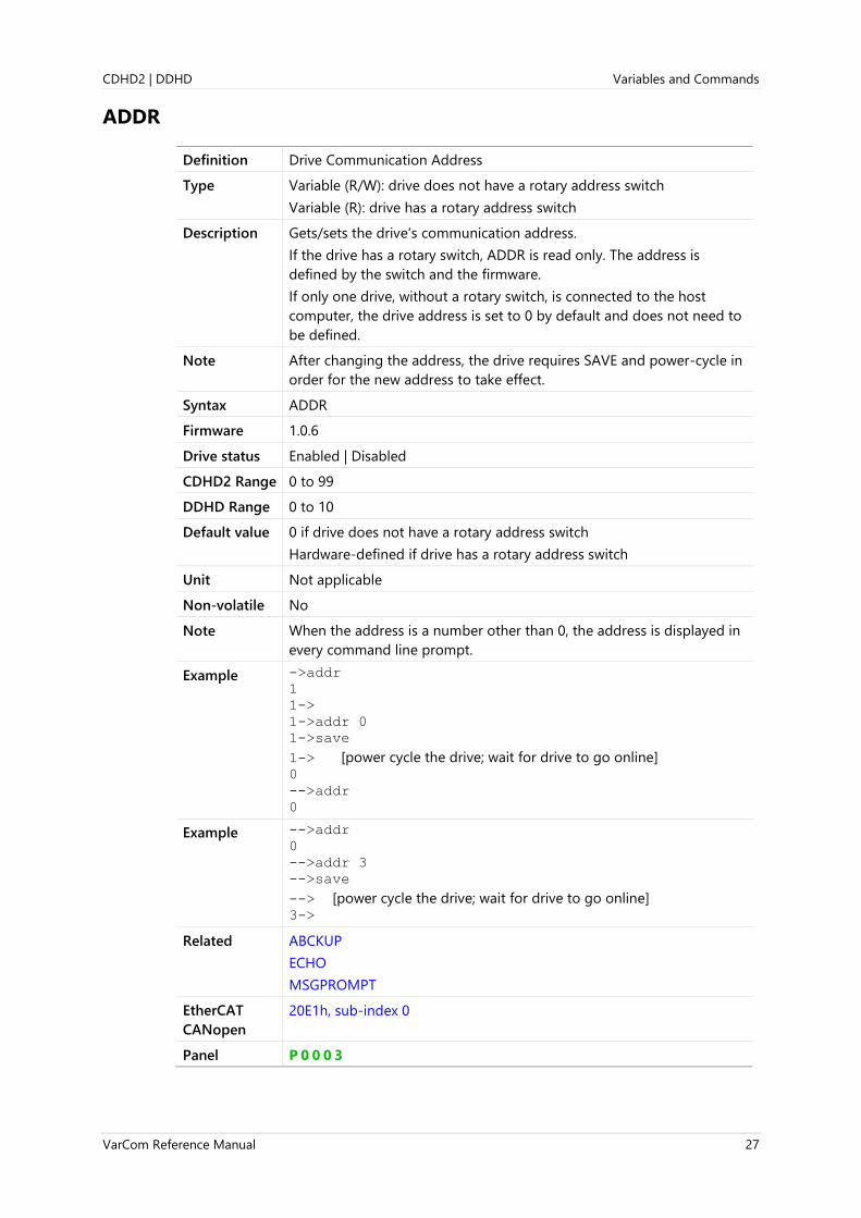
ADDR
Definition Drive Communication Address
Type Variable (R/W): drive does not have a rotary address switch
Variable (R): drive has a rotary address switch
Description Gets/sets the drive’s communication address.
If the drive has a rotary switch, ADDR is read only. The address is
defined by the switch and the firmware.
If only one drive, without a rotary switch, is connected to the host
computer, the drive address is set to 0 by default and does not need to
be defined.
Note After changing the address, the drive requires SAVE and power-cycle in
order for the new address to take effect.
Syntax ADDR
Firmware 1.0.6
Drive status Enabled | Disabled
CDHD2 Range 0 to 99
DDHD Range 0 to 10
Default value 0 if drive does not have a rotary address switch
Hardware-defined if drive has a rotary address switch
Unit Not applicable
Non-volatile No
Note When the address is a number other than 0, the address is displayed in
every command line prompt.
Example ->addr
1
1->
1->addr 0
1->save
1-> [power cycle the drive; wait for drive to go online] 0
-->addr
0
Example -->addr
0
-->addr 3
-->save
--> [power cycle the drive; wait for drive to go online] 3->
Related ABCKUP
ECHO
MSGPROMPT
EtherCAT
CANopen
20E1h, sub-index 0
Panel P 0 0 0 3
Variables and Commands CDHD2 | DDHD
28 VarCom Reference Manual
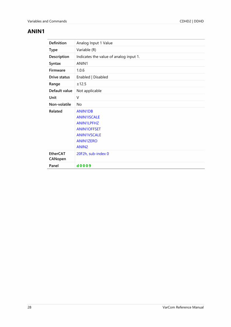
ANIN1
Definition Analog Input 1 Value
Type Variable (R)
Description Indicates the value of analog input 1.
Syntax ANIN1
Firmware 1.0.6
Drive status Enabled | Disabled
Range ±12.5
Default value Not applicable
Unit V
Non-volatile No
Related ANIN1DB
ANIN1ISCALE
ANIN1LPFHZ
ANIN1OFFSET
ANIN1VSCALE
ANIN1ZERO
ANIN2
EtherCAT
CANopen
20F2h, sub-index 0
Panel d 0 0 0 9

CDHD2 | DDHD Variables and Commands
VarCom Reference Manual 29
ANIN1DB
Definition Analog Input 1 Deadband
Type Variable (R/W)
Description Gets/sets the deadband of analog input 1.
If the absolute value of the analog input signal is less than this value, no
analog command signal is generated.
This function is useful for preventing the drive from responding to
voltage noise near the zero point of the analog input.
If ANIN1DB = 0.6, for example, the actual deadband range is -600 mV
to +600 mV, and no motor movement occurs when the analog input
voltage is within this range.
Syntax Read: ANIN1DB
Write: ANIN1DB <value>
Firmware 1.0.6
Drive status Enabled | Disabled
Range 0 to 10
Default value 0.000
Unit V
Non-volatile Yes
Related ANIN1
ANIN2LPFHZ
EtherCAT
CANopen
20F3h, sub-index 0
Panel P 4 2 0 0
Variables and Commands CDHD2 | DDHD
30 VarCom Reference Manual
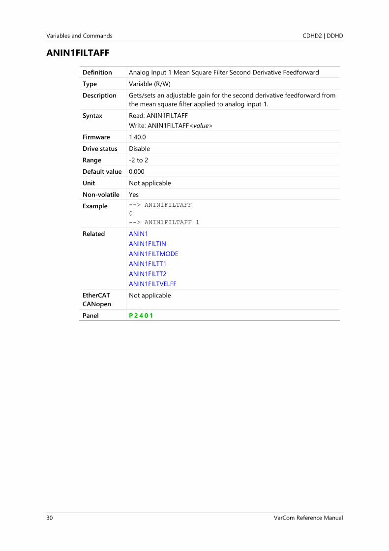
ANIN1FILTAFF
Definition Analog Input 1 Mean Square Filter Second Derivative Feedforward
Type Variable (R/W)
Description Gets/sets an adjustable gain for the second derivative feedforward from
the mean square filter applied to analog input 1.
Syntax Read: ANIN1FILTAFF
Write: ANIN1FILTAFF<value>
Firmware 1.40.0
Drive status Disable
Range -2 to 2
Default value 0.000
Unit Not applicable
Non-volatile Yes
Example --> ANIN1FILTAFF
0
--> ANIN1FILTAFF 1
Related ANIN1
ANIN1FILTIN
ANIN1FILTMODE
ANIN1FILTT1
ANIN1FILTT2
ANIN1FILTVELFF
EtherCAT
CANopen
Not applicable
Panel P 2 4 0 1

CDHD2 | DDHD Variables and Commands
VarCom Reference Manual 31
ANIN1FILTIN
Definition Analog Input 1 Value Before Mean Square Filter
Type Variable (R)
Description Value of the analog input 1 signal before the mean square filter is
applied.
Syntax ANIN1FILTIN
Firmware 1.40.0
Drive status Enabled | Disabled
Range ±12.5
Default value 0.000
Unit V
Non-volatile Yes | No
Related ANIN1
ANIN1FILTAFF
ANIN1FILTMODE
ANIN1FILTT1
ANIN1FILTT2
ANIN1FILTVELFF
EtherCAT
CANopen
Not applicable
Panel P 2 4 0 2

Variables and Commands CDHD2 | DDHD
32 VarCom Reference Manual
ANIN1FILTMODE
Definition Analog Input 1 Mean Square Filter
Type Variable (R/W)
Description Defines whether or not the mean square filter on the analog input 1
signal is activated.
Syntax Read: ANIN1FILTMODE
Write: ANIN1FILTMODE <value>
Firmware 1.40.x
Drive status Disabled
Range 0 = Mean square filter not activated
1 = Mean square filter activated
Default value 0
Unit Not applicable
Non-volatile Yes
Example --> ANIN1FILTMODE
0
--> ANIN1FILTMODE 1
Related ANIN1
ANIN1FILTAFF
ANIN1FILTIN
ANIN1FILTT1
ANIN1FILTT2
ANIN1FILTVELFF
EtherCAT
CANopen
Not applicable
Panel P 2 4 0 3

CDHD2 | DDHD Variables and Commands
VarCom Reference Manual 33
ANIN1FILTT1
Definition Analog Input 1 Filter Depth
Type Variable (R/W)
Description Gets/sets the filtering time of the mean square filter on the analog input
1 signal, in 125 μs quanta.
Syntax Read: ANIN1FILTT1
Write: ANIN1FILTT1 <value>
Firmware 1.40.0
Drive status Disabled
Range 0.375 to 32
Default value 2.000
Unit ms
Non-volatile Yes
Example --> ANIN1FILTT1
2.000 [ms]
--> ANIN1FILTT1 3
Related ANIN1
ANIN1FILTAFF
ANIN1FILTIN
ANIN1FILTMODE
ANIN1FILTT2
ANIN1FILTVELFF
EtherCAT
CANopen
Not applicable
Panel P 2 4 0 4

Variables and Commands CDHD2 | DDHD
34 VarCom Reference Manual
ANIN1FILTT2
Definition Analog Input 1 MSQ Filter Depth First and Second Derivative
Type Variable (R/W)
Description Gets/sets the filtering time of the mean square filter for the first and
second derivative analog on the input 1 signal, in 125 μs quanta.
Syntax Read: ANIN1FILTT2
Write: ANIN1FILTT3 <value>
Firmware 1.40.0
Drive status Disabled
Range 0 to 32
Default value 4.000
Unit ms
Non-volatile Yes
Example --> ANIN1FILTT2
4.000 [ms]
--> ANIN1FILTT2 3
Related ANIN1
ANIN1FILTAFF
ANIN1FILTIN
ANIN1FILTMODE
ANIN1FILTT1
ANIN1FILTVELFF
EtherCAT
CANopen
Not applicable
Panel P 2 4 0 5

CDHD2 | DDHD Variables and Commands
VarCom Reference Manual 35
ANIN1FILTVELFF
Definition Analog Input 1 MSQ Filter First Derivative Feedforward
Type Variable (R/W)
Description Gets/sets an adjustable gain for the first derivative feedforward from the
mean square filter applied to analog input 1.
Syntax Read: ANIN1FILTVELFF
Write: ANIN1FILTVELFF <value>
Firmware 1.40.0
Drive status Enabled | Disabled
Range -32 to 32
Default value 0.000
Unit ms
Non-volatile Yes
Related ANIN1
ANIN1FILTAFF
ANIN1FILTIN
ANIN1FILTMODE
ANIN1FILTT1
ANIN1FILTT2
EtherCAT
CANopen
Not applicable
Panel P 2 4 0 6
Variables and Commands CDHD2 | DDHD
36 VarCom Reference Manual
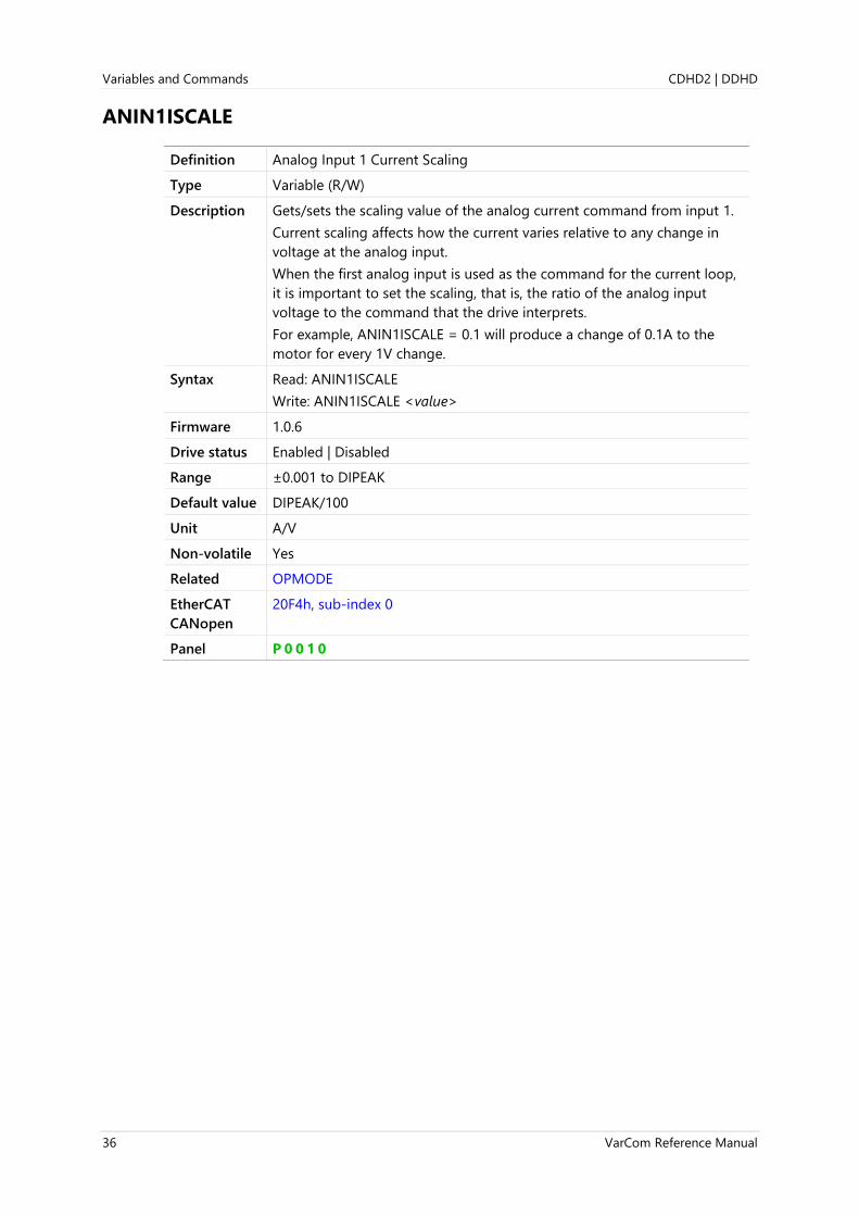
ANIN1ISCALE
Definition Analog Input 1 Current Scaling
Type Variable (R/W)
Description Gets/sets the scaling value of the analog current command from input 1.
Current scaling affects how the current varies relative to any change in
voltage at the analog input.
When the first analog input is used as the command for the current loop,
it is important to set the scaling, that is, the ratio of the analog input
voltage to the command that the drive interprets.
For example, ANIN1ISCALE = 0.1 will produce a change of 0.1A to the
motor for every 1V change.
Syntax Read: ANIN1ISCALE
Write: ANIN1ISCALE <value>
Firmware 1.0.6
Drive status Enabled | Disabled
Range ±0.001 to DIPEAK
Default value DIPEAK/100
Unit A/V
Non-volatile Yes
Related OPMODE
EtherCAT
CANopen
20F4h, sub-index 0
Panel P 0 0 1 0

CDHD2 | DDHD Variables and Commands
VarCom Reference Manual 37
ANIN1LPFHZ
Definition Analog Input 1 Filter
Type Variable (R/W)
Description Gets/sets the corner frequency of a first order (low pass) filter that is
applied to analog input 1.
This function is useful for filtering out high frequency noise from the
analog input, or for limiting the rate of change of that signal.
The ANIN1LPFHZ value represents the corner frequency of the filter. This
filter is always present and is adjusted automatically as the analog input
sampling rate changes for different operational modes.
Note If ANIN1LPFHZ is set to 10000, the filter will have no effect on the analog
input value.
Syntax Read: ANIN1LPFHZ
Write: ANIN1LPFHZ <value>
Firmware 1.0.6
Drive status Enabled | Disabled
Range 10 to 10000
Default value 1000
Unit Hz
Non-volatile Yes
Related ANIN1
ANIN1DB
EtherCAT
CANopen
20F5h, sub-index 0
Panel P 4 2 0 7

Variables and Commands CDHD2 | DDHD
38 VarCom Reference Manual
ANIN1OFFSET
Definition Analog Input 1 Offset
Type Variable (R/W)
Description Gets/sets the offset voltage for analog input 1. Used to compensate for
the analog input signal offset or drift.
The offset can also be set by a zeroing procedure, using the command
ANIN1ZERO.
The drive can receive an analog input signal in the range of ±10V. The
drive uses the value stored in the ANIN1 variable to command the
velocity of the motor or the current applied to the motor. The default
correlation between the actual input signal and the value of ANIN1 is
±10V = ±10000 mV. However, some applications provide, or require, a
different analog input signal range.
The drive analog offset function (ANIN1OFFSET) modifies the range
correlation of the analog input signal and the velocity loop command
(ANIN1). However, the value of ANIN1 remains ±10V; the upper value
cannot be greater than 10V and the lower value cannot be less than -10V.
For example, if ANIN1OFFSET = 5000, an analog input signal range of
±10V equates to a command range of -5000 mV to +10000 mV. Motor
movement is in response to a range of -5V to 10V on the input.
Syntax Read: ANIN1OFFSET
Write: ANIN1OFFSET <value>
Firmware 1.0.6
Drive status Enabled | Disabled
Range ±10
Default value 0.000
Unit V
Non-volatile Yes
Related ANIN1
ANIN1ZERO
EtherCAT
CANopen
20F6h, sub-index 0
Panel P 4 2 0 8
CDHD2 | DDHD Variables and Commands
VarCom Reference Manual 39
ANIN1VSCALE
Definition Analog Input 1 Velocity Scaling
Type Variable (R/W)
Description Gets/sets the scaling of the analog velocity command from input 1.
Velocity scaling affects how the motor speed will vary as a result of any
change in voltage at the analog velocity command.
When the first analog input is used as the command for the velocity loop,
it is important to set the scaling, that is, the ratio of the analog input
voltage to the command that the drive interprets.
For example, if ANIN1VSCALE = 500 and UNITSROTVEL=1 (rpm), the
result will be a variation of 500 rpm in the motor velocity for every 1V
change.
Syntax Read: ANIN1VSCALE
Write: ANIN1VSCALE <value>
Firmware 1.0.6
Drive status Enabled | Disabled
Range If MOTORTYPE 0 (Rotary):
UNITSROTVEL 0 = ±(0.001 to 3999.999)
UNITSROTVEL 1 = ±(0.06 to 239999.94)
UNITSROTVEL 2 = ±(0.36 to 1439999.64)
If MOTORTYPE 2 (Linear):
UNITSLINVEL 1 = ±(0.032 to 127999.96)
Default value If MOTORTYPE 0 (Rotary):
UNITSROTVEL 0 = 0.001
UNITSROTVEL 1 = 0.060
UNITSROTVEL 2 = 0.360
If MOTORTYPE 2 (Linear):
UNITSLINVEL 1 = 0.032
Unit If MOTORTYPE 0 (Rotary):
UNITSROTVEL 0 = rps/V
UNITSROTVEL 1 = rpm/V
UNITSROTVEL 2 = (deg/s)/V
If MOTORTYPE 2 (Linear):
UNITSLINVEL 1 = (mm/s)/V
Non-volatile Yes
Related OPMODE
EtherCAT
CANopen
20F7h, sub-index 0
Panel P 0 0 0 9

Variables and Commands CDHD2 | DDHD
40 VarCom Reference Manual
ANIN1ZERO
Definition Analog Input 1 Zeroing
Type Command
Description Causes the value of the analog input 1 signal to become 0 by modifying
the analog offset value (ANIN1OFFSET).
This command samples the analog input 64 times, calculates an average,
and then adjusts ANIN1OFFSET to cancel out any input offset that may be
present from such factors as drift and noise.
Syntax ANIN1ZERO
Firmware 1.0.6
Drive status Enabled | Disabled
Range Not applicable
Default value Not applicable
Unit Not applicable
Non-volatile Not applicable
Related ANIN1OFFSET
EtherCAT
CANopen
20F8h, sub-index 0
Panel C 0 0 0 9

CDHD2 | DDHD Variables and Commands
VarCom Reference Manual 41
ANIN2
Definition Analog Input 2 Value
Type Variable (R)
Description Indicates the value of analog input 2.
Syntax ANIN2
Firmware 1.0.6
Drive status Enabled | Disabled
Range ±12.5
Default value Not applicable
Unit V
Non-volatile No
Related ANIN1
ANIN2MODE
EtherCAT
CANopen
20F9h, sub-index 0
Panel d 0 0 1 0

Variables and Commands CDHD2 | DDHD
42 VarCom Reference Manual
ANIN2DB
Definition Analog Input 2 Deadband
Type Variable (R/W)
Description Gets/sets the deadband of analog input 2.
If the absolute value of the analog input signal is less than this value, no
analog command signal is generated.
Syntax Read: ANIN2DB
Write: ANIN2DB <value>
Firmware 1.0.6
Drive status Enabled | Disabled
Range 0 to 10
Default value 0.000
Unit V
Non-volatile Yes
Related ANIN1DB
ANIN2
ANIN2LPFHZ
EtherCAT
CANopen
20FAh, sub-index 0
Panel P 4 2 0 9

CDHD2 | DDHD Variables and Commands
VarCom Reference Manual 43
ANIN2ISCALE
Definition Analog Input 2 Current (Torque) Scaling
Type Variable (R/W)
Description Gets/sets the scaling of the analog current command from input 2.
When the second analog input is configured as the analog current limit,
ANIN2SCALE sets the scaling of the current limit, in amperes per volt.
The valid input voltage range for this functionality is 0-10 V, since
current and current limits in the drive are positive values only. A
negative analog input will be interpreted as zero.
Syntax Read: ANIN2ISCALE
Write: ANIN2ISCALE <value>
Firmware 1.0.6
Drive status Enabled | Disabled
Range ±0.001 to DIPEAK
Default value DIPEAK/100
Unit A/V
Non-volatile Yes
Related ANIN1ISCALE
ANIN2
ANIN2MODE
EtherCAT
CANopen
20FBh, sub-index 0
Panel P 4 2 1 0

Variables and Commands CDHD2 | DDHD
44 VarCom Reference Manual
ANIN2LPFHZ
Definition Analog Input 2 Filter
Type Variable (R/W)
Description Gets/sets the corner frequency of a first order filter that is applied to
analog input 2.
Note If ANIN2LPFHZ is set to 10000, the filter will have no effect on the analog
input value.
Syntax Read: ANIN2LPFHZ
Write: ANIN2LPFHZ <value>
Firmware 1.0.6
Drive status Enabled | Disabled
Range 10 to 10000
Default value 1000
Unit Hz
Non-volatile Yes
Related ANIN1LPFHZ
ANIN2
ANIN2DB
EtherCAT
CANopen
20FCh, sub-index 0
Panel P 4 2 1 1
CDHD2 | DDHD Variables and Commands
VarCom Reference Manual 45
ANIN2MODE
Definition Analog Input 2 Mode
Type Variable (R/W)
Description Gets/sets a value that defines the function of analog input 2.
Syntax Read: ANIN2MODE
Write: ANIN2MODE <value>
Firmware 1.0.6
Drive status Disabled
CDHD2
Range
-1= Hardware defined dual gain. ANIN2 is inactive, ANIN1 has a 16 bit
resolution, ANIN2MODE is read only.
0 = Idle. ANIN2 input voltage is read only.
1 = Dual gain - external jumper connection between the analog inputs
is required.
2 = Current limit mode - second analog input limits current command
(uses ANIN2ISCALE)
Note: Make sure hardware matches this configuration.
CDHD2
Default value
0 = When the drive is configured with Analog Input 2
-1 = When the drive is not configured with Analog Input 2
DDHD Range 0 = Unavailable.
Note: In DDHD, each axis has only one analog input:
⚫ For axis 1, analog input is ANIN1 (interface C4 – pins 24 and 49).
⚫ For axis 2, analog input is ANIN1 (interface C4 – pins 25 and 50).
Unit Not applicable
Non-volatile Yes
Related ANIN2
ANIN2ISCALE
EtherCAT
CANopen
2100h, sub-index 0
Panel P 4 2 1 2
Variables and Commands CDHD2 | DDHD
46 VarCom Reference Manual
ANIN2OFFSET
Definition Analog Input 2 Offset
Type Variable (R/W)
Description Gets/sets the offset voltage for analog input 2. Used to compensate for
the analog input signal offset or drift.
The offset can also be set by a zeroing procedure, using the command
ANIN2ZERO.
Syntax Read: ANIN2OFFSET
Write: ANIN2OFFSET <value>
Firmware 1.0.6
Drive status Enabled | Disabled
Range ±10
Default value 0.000
Unit V
Non-volatile Yes
Related ANIN1OFFSET
ANIN2
ANIN2ZERO
EtherCAT
CANopen
20FDh, sub-index 0
Panel P 4 2 1 3

CDHD2 | DDHD Variables and Commands
VarCom Reference Manual 47
ANIN2USER
Definition Analog Input 2 Voltage Defined in User Units
Type Variable (R)
Description Returns the value of the analog input 2 voltage converted into a user-
defined unit.
ANIN2USER is calculated as follows:
ANIN2USER = ANIN2 ( ANIN2USERNUM
ANIN2USERDEN) +
ANIN2USEROFFSET
This equation defines the number of units (ANIN2USER) that are
equivalent to a voltage value (ANIN2USERDEN).
Syntax ANIN2USER
Firmware 1.20.6
Drive status Enable | Disable
Range Not applicable
Default value Not applicable
Unit User defined
Non-volatile No
Example -->ANIN2USER
-7654
Related ANIN2USERDEN
ANIN2USERNUM
ANIN2USEROFFSET
EtherCAT
CANopen
216Dh, sub-index 0
Panel P 4 2 1 4

Variables and Commands CDHD2 | DDHD
48 VarCom Reference Manual
ANIN2USERDEN
Definition Analog Input 2 Value Conversion to ANIN2USER - Denominator
Type Variable (R/W)
Description Gets/sets the denominator value in the ANIN2USER equation:
ANIN2USER = ANIN2 ( ANIN2USERNUM
ANIN2USERDEN) +
ANIN2USEROFFSET
Syntax ANIN2USERDEN
Firmware 1.20.6
Drive status Enable | Disable
Range 1 to 2147483647
Default value 1
Unit V
Non-volatile Yes
Example --> ANIN2USERDEN
1
--> ANIN2USERDEN 1234
-->
Related ANIN2USER
ANIN2USERNUM
ANIN2USEROFFSET
EtherCAT
CANopen
216Eh, sub-index 0
Panel P 4 2 1 5

CDHD2 | DDHD Variables and Commands
VarCom Reference Manual 49
ANIN2USERNUM
Definition Analog Input 2 Value Conversion to ANIN2USER - Numerator
Type Variable (R/W)
Description Gets/sets the numerator value in the ANIN2USER equation:
ANIN2USER = ANIN2 ( ANIN2USERNUM
ANIN2USERDEN) +
ANIN2USEROFFSET
Syntax ANIN2USERNUM
Firmware 1.20.6
Drive status Enable | Disable
Range -2147483647 to 2147483647
Default value 100
Unit User defined
Non-volatile Yes
Example --> ANIN2USERNUM
100
--> ANIN2USERNUM 1234
-->
Related ANIN2USER
ANIN2USERDEN
ANIN2USEROFFSET
EtherCAT
CANopen
216Fh, sub-index 0
Panel P 4 2 1 6

Variables and Commands CDHD2 | DDHD
50 VarCom Reference Manual
ANIN2USEROFFSET
Definition Analog Input 2 Value Conversion to ANIN2USER - Offset
Type Variable (R/W)
Description Gets/sets the offset value in the ANIN2USER equation:
ANIN2USER = ANIN2 ( ANIN2USERNUM
ANIN2USERDEN) +
ANIN2USEROFFSET
Syntax Read: ANIN2USEROFFSET
Write: ANIN2USEROFFSET <value>
Firmware 1.20.6
Drive status Enable | Disable
Range -2147483647 to 2147483647
Default value 0
Unit User defined
Non-volatile Yes
Example --> ANIN2USEROFFSET
0
--> ANIN2USEROFFSET 1234
-->
Related ANIN2USER
ANIN2USERDEN
ANIN2USERNUM
EtherCAT
CANopen
2170h, sub-index 0
Panel P 4 2 1 7
CDHD2 | DDHD Variables and Commands
VarCom Reference Manual 51
ANIN2ZERO
Definition Analog Input 2 Zeroing
Type Command
Description Causes the value of the analog input 2 signal to become 0 by modifying
the analog offset value (ANIN2OFFSET).
Syntax ANIN2ZERO
Firmware 1.0.6
Drive status Enabled | Disabled
Range Not applicable
Default value Not applicable
Unit Not applicable
Non-volatile Not applicable
Related ANIN1ZERO
ANIN2
ANIN2OFFSET
EtherCAT
CANopen
20FFh, sub-index 0
Panel P 4 2 1 8
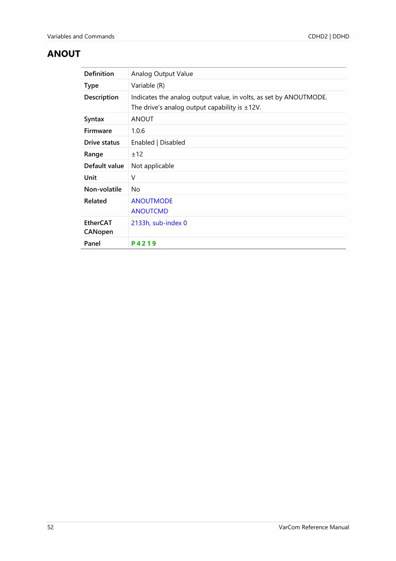
Variables and Commands CDHD2 | DDHD
52 VarCom Reference Manual
ANOUT
Definition Analog Output Value
Type Variable (R)
Description Indicates the analog output value, in volts, as set by ANOUTMODE.
The drive’s analog output capability is ±12V.
Syntax ANOUT
Firmware 1.0.6
Drive status Enabled | Disabled
Range ±12
Default value Not applicable
Unit V
Non-volatile No
Related ANOUTMODE
ANOUTCMD
EtherCAT
CANopen
2133h, sub-index 0
Panel P 4 2 1 9

CDHD2 | DDHD Variables and Commands
VarCom Reference Manual 53
ANOUTCMD
Definition Analog Output Command
Type Command
Description The analog output value set by user.
Requires ANOUTMODE=0.
Syntax ANOUTCMD {value}
Firmware 1.0.6
Drive status Enabled | Disabled
Range ±ANOUTLIM
Default value 0
Unit V
Non-volatile No
Related ANOUT
ANOUTLIM
ANOUTMODE
EtherCAT
CANopen
2134h, sub-index 0
Panel P 4 2 2 0

Variables and Commands CDHD2 | DDHD
54 VarCom Reference Manual
ANOUTISCALE
Definition Analog Output Current Scaling
Type Variable (R/W)
Description Gets/sets the scaling of the analog output voltage that represents the
motor current (I) or the current command (ICMD).
For example, if ANOUTMODE=4 (current command monitoring):
ANOUT [V] = ICMD [A] ÷ ANOUTISCALE [A/V]
Syntax ANOUTISCALE
Firmware 1.0.6
Drive status Enabled | Disabled
Range 0 to 10
Default value 0.01 DIPEAK
Unit A/V
Non-volatile Yes
Related ANOUT
ANOUTLIM
ANOUTMODE
EtherCAT
CANopen
2135h, sub-index 0
Panel P 4 2 2 1
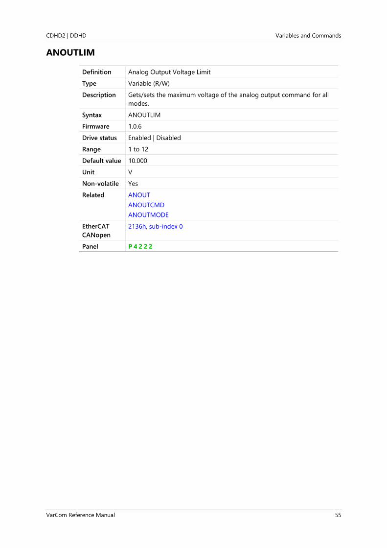
CDHD2 | DDHD Variables and Commands
VarCom Reference Manual 55
ANOUTLIM
Definition Analog Output Voltage Limit
Type Variable (R/W)
Description Gets/sets the maximum voltage of the analog output command for all
modes.
Syntax ANOUTLIM
Firmware 1.0.6
Drive status Enabled | Disabled
Range 1 to 12
Default value 10.000
Unit V
Non-volatile Yes
Related ANOUT
ANOUTCMD
ANOUTMODE
EtherCAT
CANopen
2136h, sub-index 0
Panel P 4 2 2 2

Variables and Commands CDHD2 | DDHD
56 VarCom Reference Manual
ANOUTMODE
Definition Analog Output Mode
Type Variable (R/W)
Description Gets/sets a value that defines the function of the analog output.
Known Limitation: For the first 3 seconds after power-up, DAC will
output 12V.
Syntax Read: ANOUTMODE
Write: ANOUTMODE <value>
Firmware 1.0.6
Drive status Enabled | Disabled
Range 0 = User command. Uses value set by ANOUTCMD.
1 = Tachometer mode. For velocity feedback.
2 = Equivalent current monitoring.
3 = Velocity error monitoring.
4 = Current command monitoring.
5 = Triangle wave at low frequency (0.041 Hz). For testing.
6 = Current in-phase component (IQ) monitoring.
7 = Reserved (output 0).
8 = Reserved (output 0).
9 = Reserved.
10 = Reserved.
11 = Triangle wave (10 Hz).
12 = Rectangular wave (10 Hz).
13 = Velocity command (VCMD).
14 = Deactivated (ANOUT not supported; typically due to hardware
limitation).
Default value 0
Unit Not applicable
Non-volatile Yes
Related ANOUT
ANOUTCMD
ANOUTISCALE
ANOUTLIM
ANOUTVSCALE
Note Velocity variables are scaled by ANOUTVSCALE, while current variables
are scaled by ANOUTISCALE.
EtherCAT
CANopen
2137h, sub-index 0
Panel P 4 2 2 3

CDHD2 | DDHD Variables and Commands
VarCom Reference Manual 57
ANOUTVSCALE
Definition Analog Output Velocity Scaling
Type Variable (R/W)
Description Gets/sets the scaling of the analog output voltage that represents
velocity (V).
Syntax Read: ANOUTVSCALE
Write: ANOUTVSCALE <value>
Firmware 1.0.6
Drive status Enabled | Disabled
Range If MOTORTYPE 0 (Rotary)
UNITSROTVEL 0 = -3999.999 to 3999.999
UNITSROTVEL 1 = -239999.940 to 239999.940
UNITSROTVEL 2 = -1439999.640 to 1439999.640
If MOTORTYPE 0 (Linear)
UNITSROTVEL 1 = -127999.968 to 127999.968
Default value 0
Unit If MOTORTYPE 0 (Rotary):
UNITSROTVEL 0 = rps/V
UNITSROTVEL 1 = rpm/V
UNITSROTVEL 2 = (deg/s)/V
If MOTORTYPE 2 (Linear):
UNITSLINVEL 1 = (mm/s)/V
Non-volatile Yes
Related ANOUT
ANOUTLIM
ANOUTMODE
EtherCAT
CANopen
2138h, sub-index 0
Panel P 4 2 2 4

Variables and Commands CDHD2 | DDHD
58 VarCom Reference Manual
AQBFILT
Definition Motor Encoder AB Quadrature Filter Count
Type Variable (R/W)
Description User defined value for motor encoder AB quadrature.
Quadrature encoder signals emanating from incremental encoders are
occasionally noisy. Additional transitions may be captured and counted
by the quadrature-encoder-pulse (QEP) peripheral of the DSP, resulting
in problems such as position loss and commutation loss.
To overcome such problems, the A and B signals are routed through the
FPGA, where they are filtered. The filter output will switch states only if
the incoming signal remains (mostly) at the corresponding state for a
predetermined number (AQBFILT) of FPGA internal clock intervals.
Syntax Read: AQBFILT
Write: AQBFILT <value>
Firmware 2.0.x
Drive status Enabled | Disabled
Range 0 to 100
Default value 8
Unit Not applicable
Non-volatile Yes
Related MENCAQBFILT
EtherCAT
CANopen
Not applicable

CDHD2 | DDHD Variables and Commands
VarCom Reference Manual 59
AUTOHOME
Definition Automatic Homing Mode
Type Variable (R/W)
Description Gets/sets a value that defines whether or not automatic homing will be
performed at power up.
When automatic homing mode is active, homing will be attempted as
soon as the drive is enabled for the first time after power up (even if
faults needed to be cleared first). The drive should be in a position
operation mode (OPMODE 4 or OPMODE 8).
Syntax Read: AUTOHOME
Write: AUTOHOME <value>
Firmware 1.2.12
Drive status Enabled | Disabled
Range 0 = No Action. User must initiate homing manually.
1 = Homing to be attempted after power up if conditions allow (that is,
drive is enabled by means of a serial or hardware command, and
no faults exist).
Default value 0
Unit Not applicable
Non-volatile Yes
Related HOMECMD
HOMETYPE
EtherCAT
CANopen
200Eh, sub-index 0

Variables and Commands CDHD2 | DDHD
60 VarCom Reference Manual
BAUDRATE
Definition Serial Baud Rate
Type Variable (R/W)
Description Sets the communication bit rate between the drive and host computer.
It is intended to enable more reliable communication in noisy
environments.
Changing the bit rate requires reestablishing communication with the
PC software.
Syntax Read: BAUDRATE
Write: BAUDRATE <value>
Firmware 1.3.2
Drive status Enabled | Disabled
Range 9600
19200
38400
57600
115200
Default value 115200
Unit bps
Non-volatile Yes
Related
EtherCAT
CANopen
Not applicable
Panel P 6 0 0 0

CDHD2 | DDHD Variables and Commands
VarCom Reference Manual 61
BISSCFIELDS
Definition BiSS-C Protocol Properties
Type Command
Description The drive firmware handles various BiSS-C devices according to the
communication packet structure defined by the command
BISSCFIELDS.
This command sets the number of bits allocated for transmission of
position data within a BiSS-C packet, and the number of effective bits.
It is applicable for both rotary and linear encoders.
The values used for the command arguments are taken from the
information found in the datasheet provided by the encoder
manufacturer.
Syntax BISSCFIELDS {aa bb cc dd}
where:
aa = Multi-turn Data (bits). The number of bits allocated for
transmission of multi-turn position data within a BiSS-C packet.
If using a single turn encoder, or a linear encoder, or if it is not
specified in the encoder data sheet, enter value 00.
bb = Effective Multi-turn Data (bits). The number of effective bits in
transmission of multi-turn position data.
bb cannot exceed the value of aa; typically they have the same
value.
If this value is not specified in the encoder data sheet, use the
same value as aa.
cc = Single Turn Data (bits). The number of bits allocated for
transmission of single turn (or linear) position data within a BiSS-C
packet.
dd= Effective Single Turn Data (bits).The number of effective bits in
transmission of single turn (or linear) position data.
dd cannot exceed the value of cc; typically they have the same
value.
If this value is not specified in the encoder data sheet, use the
same value as cc.
Firmware 1.20.6
Drive status Disabled
Range 0 to 27 (for each argument in command)
Default value Not applicable
Unit Not applicable
Non-volatile Not applicable
Example Multi-turn encoder: BiSS 12 bit multi-turn; 13 bit single turn
BISSCFIELDS 12 12 13 13
Example Single turn encoder: BiSS-C 26 bit
BISSCFIELDS 00 00 26 26
Example Linear encoder: BiSS 32 bit
BISSCFIELDS 00 00 18 18
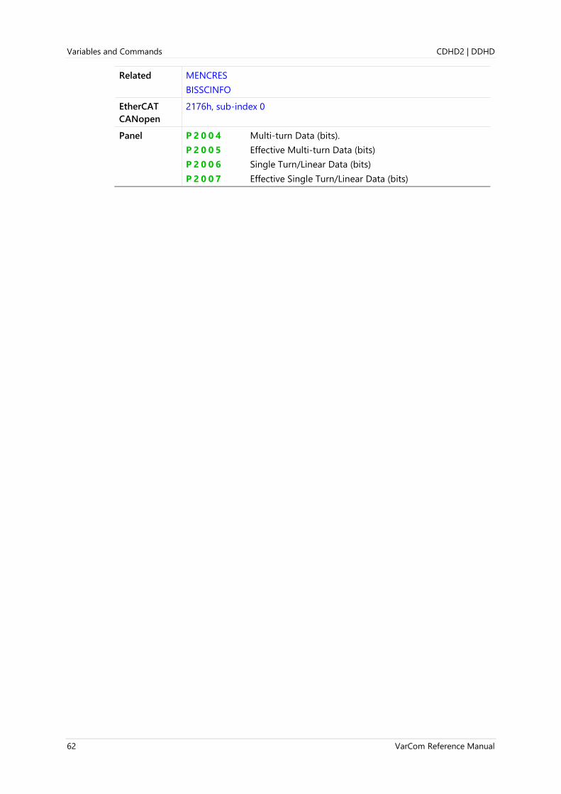
Variables and Commands CDHD2 | DDHD
62 VarCom Reference Manual
Related MENCRES
BISSCINFO
EtherCAT
CANopen
2176h, sub-index 0
Panel P 2 0 0 4 Multi-turn Data (bits).
P 2 0 0 5 Effective Multi-turn Data (bits)
P 2 0 0 6 Single Turn/Linear Data (bits)
P 2 0 0 7 Effective Single Turn/Linear Data (bits)

CDHD2 | DDHD Variables and Commands
VarCom Reference Manual 63
BISSCINFO
Definition BiSS-C Encoder Info
Type Command
Description Returns information about the BiSS-C device.
Syntax BISSCINFO
Firmware 1.20.6
Drive status Enabled | Disabled
Range Not applicable
Default value Not applicable
Unit Not applicable
Non-volatile Not applicable
EtherCAT
CANopen
Not applicable
Related BISSCFIELDS
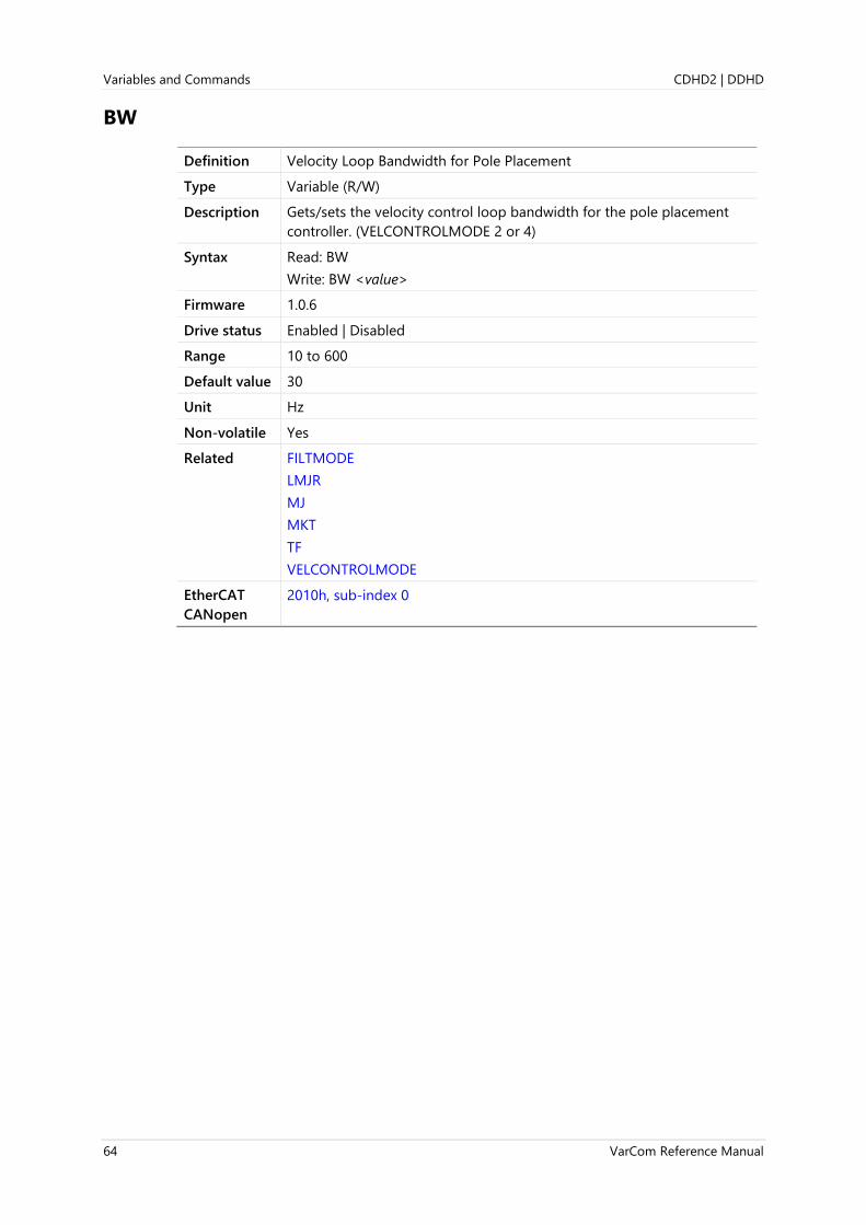
Variables and Commands CDHD2 | DDHD
64 VarCom Reference Manual
BW
Definition Velocity Loop Bandwidth for Pole Placement
Type Variable (R/W)
Description Gets/sets the velocity control loop bandwidth for the pole placement
controller. (VELCONTROLMODE 2 or 4)
Syntax Read: BW
Write: BW <value>
Firmware 1.0.6
Drive status Enabled | Disabled
Range 10 to 600
Default value 30
Unit Hz
Non-volatile Yes
Related FILTMODE
LMJR
MJ
MKT
TF
VELCONTROLMODE
EtherCAT
CANopen
2010h, sub-index 0

CDHD2 | DDHD Variables and Commands
VarCom Reference Manual 65
CANBITRATE
Definition CAN Bus Bit Rate
Type Variable (R/W)
Description Gets/sets the CAN bus bit rate.
When the drive is powered, it assumes the bit rate of any existing
communication on the CAN bus. If no such communication is detected,
the drive sets the communication rate to the CANBITRATE value.
For the CANBITRATE setting to take effect, a SAVE command followed
by a cycle power sequence must be executed.
Syntax CANBITRATE
CANBITRATE <value>
Firmware 1.3.2
Drive status Enabled | Disabled
Range 1 = 125 kbps
2 = 250 kbps
3 = 500 kbps
4 = 1000 kbps (required for CDHD2 with softMC motion controller)
Default value 3
Unit Not applicable
Non-volatile Yes
Related FBGDS
FBITPRD
EtherCAT
CANopen
Not applicable
Panel P 6 0 0 1
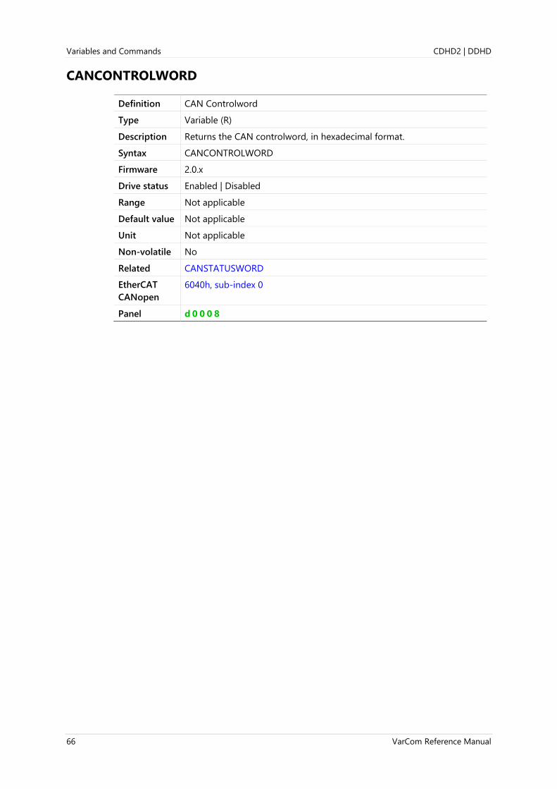
Variables and Commands CDHD2 | DDHD
66 VarCom Reference Manual
CANCONTROLWORD
Definition CAN Controlword
Type Variable (R)
Description Returns the CAN controlword, in hexadecimal format.
Syntax CANCONTROLWORD
Firmware 2.0.x
Drive status Enabled | Disabled
Range Not applicable
Default value Not applicable
Unit Not applicable
Non-volatile No
Related CANSTATUSWORD
EtherCAT
CANopen
6040h, sub-index 0
Panel d 0 0 0 8

CDHD2 | DDHD Variables and Commands
VarCom Reference Manual 67
CANSTATUSWORD
Definition CAN Statusword
Type Variable (R)
Description Returns the CAN statusword, in hexadecimal format.
Syntax CANCONTROLWORD
Firmware 2.0.x
Drive status Enabled | Disabled
Range Not applicable
Default value Not applicable
Unit Not applicable
Non-volatile No
Related CANCONTROLWORD
EtherCAT
CANopen
6041h, sub-index 0
Panel d 0 0 0 7

Variables and Commands CDHD2 | DDHD
68 VarCom Reference Manual
CHECKSUM
Definition Checksum
Type Variable (R/W)
Description Enables/disables checksum protection on messages communicated
between drive and host.
The checksum is an 8-bit value, displayed within brackets <>. For
example, 0x1F checksum is displayed as <1F> at the end of the
message before the carriage return.
Syntax Read: CHECKSUM
Write: CHECKSUM <value>
Firmware 1.0.6
Drive status Enabled | Disabled
Range 0 = Message checksum disabled
1 = Message checksum enabled
Default value 0
Unit Not applicable
Non-volatile Yes
Related COMMODE
ECHO
MSGPROMPT
EtherCAT
CANopen
Not applicable
Panel P 6 0 0 2
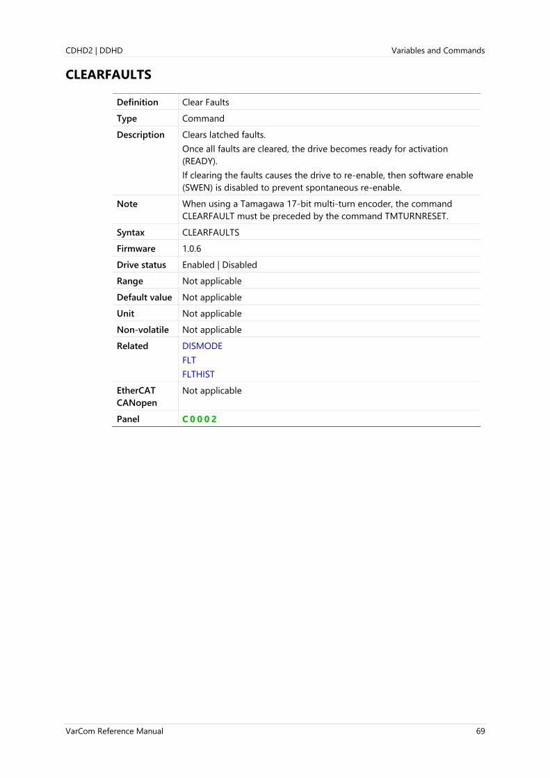
CDHD2 | DDHD Variables and Commands
VarCom Reference Manual 69
CLEARFAULTS
Definition Clear Faults
Type Command
Description Clears latched faults.
Once all faults are cleared, the drive becomes ready for activation
(READY).
If clearing the faults causes the drive to re-enable, then software enable
(SWEN) is disabled to prevent spontaneous re-enable.
Note When using a Tamagawa 17-bit multi-turn encoder, the command
CLEARFAULT must be preceded by the command TMTURNRESET.
Syntax CLEARFAULTS
Firmware 1.0.6
Drive status Enabled | Disabled
Range Not applicable
Default value Not applicable
Unit Not applicable
Non-volatile Not applicable
Related DISMODE
FLT
FLTHIST
EtherCAT
CANopen
Not applicable
Panel C 0 0 0 2

Variables and Commands CDHD2 | DDHD
70 VarCom Reference Manual
CLVD
Definition Voltage Command D Component
Type Variable (R)
Description Shows the D output of the current controller.
Syntax CLVD
Firmware 1.0.6
Drive status Enabled | Disabled
Range Internal
Default value Not applicable
Unit V
Non-volatile No
Related CLVQ
EtherCAT
CANopen
2013h, sub-index 0
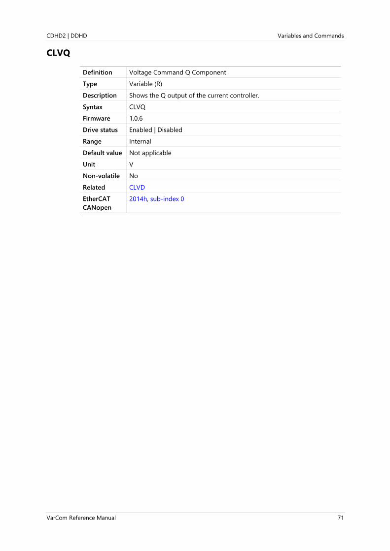
CDHD2 | DDHD Variables and Commands
VarCom Reference Manual 71
CLVQ
Definition Voltage Command Q Component
Type Variable (R)
Description Shows the Q output of the current controller.
Syntax CLVQ
Firmware 1.0.6
Drive status Enabled | Disabled
Range Internal
Default value Not applicable
Unit V
Non-volatile No
Related CLVD
EtherCAT
CANopen
2014h, sub-index 0

Variables and Commands CDHD2 | DDHD
72 VarCom Reference Manual
COMMERRMAXCNT
Definition Commutation Error Counter
Type Variable (R/W)
Description Gets/clears the variable whose value indicates the commutation error
count since COMMERRMAXCNT was last cleared.
Note Replaces RAMAXERRCNT
Syntax Read: COMMERRMAXCNT
Write: COMMERRMAXCNT 0
Firmware 1.40.0
Drive status Enabled | Disabled
Range 0 (no other value allowed)
Default value 0
Unit ms
Non-volatile No
Related COMMERRVTHRESH
COMMFLTTRESH
EtherCAT
CANopen
220Ch, sub-index 0
Panel P 7 1 0 8

CDHD2 | DDHD Variables and Commands
VarCom Reference Manual 73
COMMERRTTHRESH
Definition Commutation Error Threshold
Type Variable (R/W)
Description Motor commutation errors are typically caused by incorrect wiring,
incorrect parameters values, or encoder malfunction. The commutation
error parameters allow users to define the settings for detecting an
uncontrolled motion and declaring a fault.
COMMERRTTHRESH gets/sets the error-counter threshold value for
generating a commutation fault.
When the commutation error is detected consecutively for
COMMERRTTHRESH number of times, a commutation fault is
generated.
Note Replaces RATTHRESH, RUNAWAYTTHRESH
Syntax Read: COMMERRTTHRESH
Write: COMMERRTTHRESH <value>
Firmware 1.40.0
Drive status Enabled | Disabled
Range 0 to 3000
Default value 0
Unit ms
Non-volatile Yes
Related COMMERRVTHRESH
COMMFLTTRESH
Panel P 7 1 0 9
EtherCAT
CANopen
220Dh, sub-index 0

Variables and Commands CDHD2 | DDHD
74 VarCom Reference Manual
COMMERRVTHRESH
Definition Commutation Error Velocity Deviation
Type Variable (R/W)
Description Motor commutation errors are typically caused by incorrect wiring,
incorrect parameters values, or encoder malfunction. The commutation
error parameters allow users to define the settings for detecting an
uncontrolled motion and declaring a fault.
COMMERRVTHRESH gets/sets the threshold value of velocity deviation
that will generate a commutation fault.
Note Replaces parameter RAVTHRESH, RUNAWAYVTHRESH
Syntax Read: COMMERRVTHRESH
Write: COMMERRVTHRESH <value>
Firmware 1.40.0
Drive status Enable | Disable
Range 0 to VLIM
Default value If MOTORTYPE 0 (Rotary):
If UNITSROTVEL 0 = 1.000
If UNITSROTVEL 1 = 60.000
If UNITSROTVEL 2 = 359.999
If UNITSROTVEL 3 = 1(PNUM/PDEN)
If MOTORTYPE 2 (Linear):
UNITSLINVEL 1 = 1MPITCH
UNITSLINVEL 2 = 1(PNUM/PDEN)
Unit If MOTORTYPE 0 (Rotary):
If UNITSROTVEL 0 = rps
If UNITSROTVEL 1 = rpm
If UNITSROTVEL 2 = deg/s
If UNITSROTVEL 3 = user/s
If MOTORTYPE 2 (Linear):
UNITSLINVEL 1 = mm/s
UNITSLINVEL 2 = user/s
Non-volatile Yes
Related COMMFLTTRESH
Panel P 7 1 1 0
EtherCAT
CANopen
220Eh, sub-index 0

CDHD2 | DDHD Variables and Commands
VarCom Reference Manual 75
COMMFLTTRESH
Definition Commutation Error Index Position Deviation
Type Variable (R/W)
Description Motor commutation errors are typically caused by incorrect wiring,
incorrect parameters values, or encoder malfunction. The commutation
error parameters allow users to define the settings for detecting an
uncontrolled motion and declaring a fault.
COMMFLTTRESH gets/sets the value of commutation deviation from
the index position that will generate a commutation fault.
After commutation is initialized, the commutation angle at the index
crossing position is monitored; if the angle deviates from the initial
location by more than COMMFLTTRESH, a commutation fault is
declared.
The fault disables the drive according to the DISMODE setting for a
(still) reliable feedback condition.
The error message is “AB Quadrature Commutation Fault”, and the
digital display shows error code F r 3 9 | r39.
Use COMMFLTTRESH 0 to disable this function.
Notes Applicable for use only with encoders that have an index pulse.
COMMFLTTRESH; not COMMFLTHRESH
Syntax Read: COMMFLTTRESH
Write: COMMFLTTRESH <value>
Firmware 1.15.xx
Drive status Enabled | Disabled
Range 0 to 20
Default value 2
Unit Electrical degree
Non-volatile Yes
Related COMMERRMAXCNT
COMMERRTTHRESH
COMMERRVTHRESH
DISMODE
ELECTANGLE
FEEDBACKTYPE
MENCTYPE
MPHASE
EtherCAT
CANopen
220Fh, sub-index 0

Variables and Commands CDHD2 | DDHD
76 VarCom Reference Manual
COMMODE
Definition Communication Interface Mode
Type Variable (R/W)
Description Gets/sets the communication interface mode.
COMMODE 1 is applicable only for EtherCAT and CANopen drives.
Syntax Read: COMMODE
Write: COMMODE <value>
Firmware 1.0.6
Drive status Disabled
Range 0 = Serial RS232/USB communication enabled. EtherCAT/CANopen
communication disabled. Drive can be software enabled at power-
up (SWENMODE).
Reference commands accepted via serial/pulse /analog interfaces
only.
1 = For EtherCAT/CANopen drive only.
EtherCAT/CANopen communication is enabled.
Serial RS232/USB communication can be used as a utility for
monitoring and changing parameters with limited functionality.
Reference commands cannot be received via serial/ pulse/analog
interfaces.
Default value 0 = For analog drive
1 = For CAN/EtherCAT drive
Unit Not applicable
Non-volatile Yes
Related CHECKSUM
MSGPROMPT
SWENMODE
Panel P 0 0 0 0
EtherCAT
CANopen
Not applicable

CDHD2 | DDHD Variables and Commands
VarCom Reference Manual 77
CONFIG
Definition Configure Drive
Type Command
Description Configures the current control and other internal drive mechanisms
based on the configuration set. Since this configuration procedure
depends on several variables, it is not executed automatically following
parameter changes.
The configuration process may take more than a few seconds to
complete. Be sure the configuration has completed before attempting to
enable the drive.
When configuration is required, the HMI display shows F – 1 (-1).
CONFIG is required after modifying the value of certain parameters,
including, but not necessarily limited to, the following:
DIR
ENCOUTMODE
ENCOUTRES
FEEDBACKTYPE
KCBEMF
KCD
KCFF
KCI
KCP
MENCRES
MENCTYPE
MFBDIR
MFBMODE
MICONT
MIPEAK
MJ
MKF
MKT
ML
MLGAINC
MLGAINP
MOTORCOMMTYPE
MOTORTYPE
MPITCH
MPOLES
MR
MRESPOLES
MSININT
MSPEED
PWMFRQ
VBUS
VLIM
Syntax CONFIG
Firmware 1.0.6
Drive status Disabled
Range Not applicable
Default value Not applicable
Unit Not applicable
Non-volatile Not applicable
Related MENCTYPE
ML
Panel C 0 0 0 5
EtherCAT
CANopen
2002h, sub-index 0
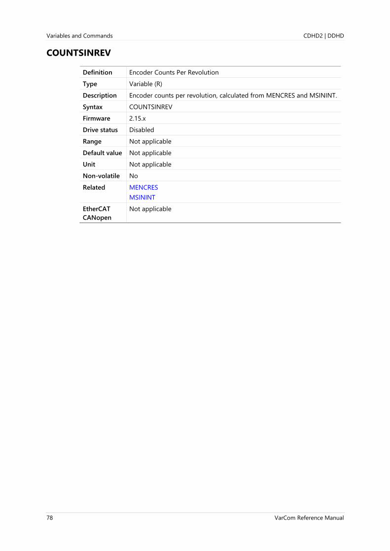
Variables and Commands CDHD2 | DDHD
78 VarCom Reference Manual
COUNTSINREV
Definition Encoder Counts Per Revolution
Type Variable (R)
Description Encoder counts per revolution, calculated from MENCRES and MSININT.
Syntax COUNTSINREV
Firmware 2.15.x
Drive status Disabled
Range Not applicable
Default value Not applicable
Unit Not applicable
Non-volatile No
Related MENCRES
MSININT
EtherCAT
CANopen
Not applicable

CDHD2 | DDHD Variables and Commands
VarCom Reference Manual 79
CUSTOMERID
Definition Customer ID
Type Variable (R/W)
Description Gets/sets a customer ID assigned to the drive unit.
Syntax Read: CUSTOMERID
Write: CUSTOMERID <value>
Firmware 1.41.9
Drive status Enabled | Disabled
Range 0 to 4294967295
Default value 0
Unit Not applicable
Non-volatile Yes
Related
EtherCAT
CANopen
Not applicable

Variables and Commands CDHD2 | DDHD
80 VarCom Reference Manual
DEC
Definition Motor Deceleration
Type Variable (R/W)
Description Gets/sets the deceleration value of the motor (in motor feedback units)
or the load (in secondary feedback units), according to SFBMODE.
MDEC and SFBDEC mirror the value of DEC in order to maintain the
correct value of motor feedback or load feedback if SFBMODE changes.
⚫ If SFBMODE=1 (dual loop control), the value of ACC is automatically
written to SFBDEC; conversely, any the value of SFBDEC is
automatically written to DEC.
⚫ If SFBMODE=0 (single loop control), the value of DEC is
automatically written to MDEC; conversely, the value of MDEC is
automatically written to DEC.
It is therefore sufficient to write values to DEC. MDEC and SFBDEC will
be updated accordingly.
Syntax Read: DEC
Write: DEC <value>
Firmware 1.0.6 (enhanced in 2.0.x)
Drive status Enabled | Disabled
Range If MOTORTYPE 0 (Rotary):
UNITSROTACC 0 = 0.004 to 16666.666
UNITSROTACC 1 = 0.23 to 1000000
UNITSROTACC 2 = 1.38 to 6000000
If MOTORTYPE 2 (Linear):
UNITSLINACC 1 = 0.12 to 533333.333
Default value If MOTORTYPE 0 (Rotary):
UNITSROTACC 0 = 10.000
UNITSROTACC 1 = 600.000
UNITSROTACC 2 = 3600.000
UNITSROTACC 3 = 50.000
If MOTORTYPE 2 (Linear):
UNITSLINACC 1 = 320.000
Unit If MOTORTYPE 0 (Rotary):
UNITSROTACC 0 = rps/s
UNITSROTACC 1 = rpm/s
UNITSROTACC 2 = deg/s2
If MOTORTYPE 2 (Linear):
UNITSLINACC 1 = mm/s2
Non-volatile Yes

CDHD2 | DDHD Variables and Commands
VarCom Reference Manual 81
Related ACC
ANIN1
DECSTOP
J
MDEC
SFBDEC
SFBMODE
STEP
UNITSROTACC
EtherCAT
CANopen
6084h, sub-index 0

Variables and Commands CDHD2 | DDHD
82 VarCom Reference Manual
DECSTOP
Definition Active Disable Deceleration
Type Variable (R/W)
Description Gets/sets the deceleration value for an Active Disable or emergency
stop.
Syntax Read: DECSTOP
Write: DECSTOP <value>
Firmware 1.0.6
Drive status Enabled | Disabled
Range If MOTORTYPE 0 (Rotary):
UNITSROTACC 0 = 0.004 to 16666.666
UNITSROTACC 1 = 0.23 to 1000000
UNITSROTACC 2 = 1.38 to 6000000
If MOTORTYPE 2 (Linear):
UNITSLINACC 1 = 0.12 to 533333.333
Default value If MOTORTYPE 0 (Rotary):
UNITSROTACC 0 = 1666.667
UNITSROTACC 1 = 100000.000
UNITSROTACC 2 = 600000.000
If MOTORTYPE 2 (Linear):
UNITSLINACC 1 = 53333.333
Unit If MOTORTYPE 0 (Rotary):
UNITSROTACC 0 = rps/s
UNITSROTACC 1 = rpm/s
UNITSROTACC 2 = deg/s2
If MOTORTYPE 2 (Linear):
UNITSLINACC 1 = mm/s2
Non-volatile Yes
Related ACC
DEC
UNITSROTACC
EtherCAT
CANopen
6085h, sub-index 0
Panel P 0 0 1 7

CDHD2 | DDHD Variables and Commands
VarCom Reference Manual 83
DECSTOPTIME
Definition Active Disable Deceleration Time
Type Variable (R/W)
Description Gets/sets the deceleration time for an Active Disable or emergency
stop.
DECSTOPTIME will override DECSTOP if the resulting deceleration level
exceeds DECSTOP.
Syntax Read: DECSTOPTIME
Write: DECSTOPTIME <value>
Firmware 1.2.12
Drive status Disabled
Range 0 to 6500
Default value 0
Unit ms
Non-volatile Yes
Related DECSTOP
DISMODE
EtherCAT
CANopen
2049h, sub-index 0
Panel P 7 1 0 2

Variables and Commands CDHD2 | DDHD
84 VarCom Reference Manual
DELAY
Definition Script Delay
Type Command
Description Allows a pause during the execution of a drive script command.
Syntax DELAY {time}
Firmware 1.4.4
Drive status Enabled | Disabled
Range 0 to 65535
Default value Not applicable
Unit ms
Non-volatile No
Related DRIVESCRIPT
DRIVESCRIPTST
EtherCAT
CANopen
Not applicable

CDHD2 | DDHD Variables and Commands
VarCom Reference Manual 85
DICONT
Definition Drive Continuous Current
Type Variable (R)
Description Indicates the continuous rated current for the drive (sinusoidal peak).
This is a hardware-defined read-only variable that is detected
automatically by the drive.
Syntax DICONT
Firmware 1.0.6
Drive status Disabled
Range Not applicable
Default value Hardware defined
Unit A
Non-volatile Yes
Related DIPEAK
FOLD
IFOLD
MICONT
EtherCAT
CANopen
207Ch, sub-index 0
Panel P 7 0 0 0

Variables and Commands CDHD2 | DDHD
86 VarCom Reference Manual
DIFPORTMODE
Definition Differential Port Mode
Type Variable (R/W)
Description Defines the differential (RS422) digital port hardware and functionality.
Syntax Read: DIFPORTMODE <value1>
Write: DIFPORTMODE <value1><value2>
Firmware 2.0.x
Drive status Enabled | Disabled
Range <value1> = Differential (RS422) output port:
1 = Port 1: C2 (pins 4, 22)
2 = Port 2: C2 (pins 5, 23)
3 = Port 3: C2 (pins 6, 24)
<value2> = Output functionality:
0 = Encoder simulation output
1 = Position compare output module 1 (PCOM1)
2 = Position compare output module 2 (PCOM2)
Default value value1: Not applicable
value2: 0
Unit Not applicable
Non-volatile Yes
Related PCOMCNTRL1
PCOMCNTRL2
EtherCAT
CANopen
21A3h, sub-index 0
CDHD2 | DDHD Variables and Commands
VarCom Reference Manual 87
DIPEAK
Definition Drive Peak Current
Type Variable (R)
Description Indicates the rated peak current of the drive (sinusoidal peak). This is a
hardware-defined read-only variable.
Syntax DIPEAK
Firmware 1.0.6
Drive status Disabled
Range Not applicable
Default value Hardware defined
Unit A
Non-volatile Yes
Related DICONT
IMAX
MIPEAK
EtherCAT
CANopen
207Bh, sub-index 0
Panel P 7 0 0 1

Variables and Commands CDHD2 | DDHD
88 VarCom Reference Manual
DIR
Definition Motor Direction
Type Variable (R/W)
Description DIR is used to invert the values of position feedback (PFB), velocity (V)
and current (ICMD), thereby inverting the direction of motor movement.
When DIR=3, the values of variables PFB, V and ICMD are inverted and
the actual direction of motor movement is reversed. Other variables
(MECHANGLE, ELECTANGLE, HWPOS) remain unchanged.
When the value of DIR is changed, CONFIG is required.
The value of DIR depends on the bit values.
Bit 0: PFB and V direction
Bit 1: ICMD (current) direction
Bit 1 Bit 0 Value
0 0 = 0
0 1 = 1 Use only for backward compatibility.
1 0 = 2 Not in use. Not valid.
1 1 = 3
Syntax Read: DIR
Write: DIR <value>
Firmware 1.0.6
Drive status Disabled
Range 0 = Normal value of PFB, V and ICMD.
1 = Inverted value of PFB and V. Normal value of ICMD.
3 = Inverted value of PFB, V and ICMD.
Default value 0
Unit Not applicable
Non-volatile Yes
Related MFBDIR
MOTORSETUP
MPHASE
PFB
V
EtherCAT
CANopen
2045h, sub-index 0
Panel P 0 0 1 8
CDHD2 | DDHD Variables and Commands
VarCom Reference Manual 89
DISMODE
Definition Disable Mode
Type Variable (R/W)
Description The disabling of the drive may be the result of an explicit command
from the motion controller or the drive’s own response to a fault
condition. When the drive becomes disabled, the Disable Mode function
can be used in certain cases (see Note below) to bring the motor to a
fast stop before power to the motor is shut off. This reduces the amount
of motor coasting.
DISMODE gets/sets a value that defines the Disable mode.
The Disable mode consists of two mechanisms:
⚫ Active Disable brings the motor to a stop by means of a controlled
deceleration to zero velocity, and then disables the drive. Active
Disable cannot be applied when the drive is operating in a current
control mode (OPMODE 2 or OPMODE 3).
⚫ Dynamic Brake holds the motor while the drive is disabled by
applying only the motor’s back-EMF to the stopping current; it can
therefore be used even in the event of feedback loss.
Syntax Read: DISMODE
Write: DISMODE <value>
Firmware 1.0.6
Drive status Enabled | Disabled
Range 0 = No active disabling; no dynamic braking.
1 = No active disabling; dynamic braking on fault only.
2 = No active disabling; dynamic braking on any disable.
3 = Active disabling on fault*; no dynamic braking.
4 = Active disabling on fault*; dynamic braking on fault only.
5 = Active disabling on fault*; dynamic braking on any disable.
Note * When supported. Faults that require immediate disable (to prevent
drive damage) and feedback faults that might cause a commutation
error (runaway motor) cannot issue Active Disable.
In DISMODE 4 and 5 both Active Disable and Dynamic Brake are
supported. In these modes, Active Disable brings the motor to a stop,
and Dynamic Brake is activated after DISTIME.
Note Even when DISMODE=0 and DISTIME=0, a few milliseconds will elapse
from the time of the disable request until the actual disable occurs.
Default value 0
Unit Not applicable
Non-volatile Yes
Related DECSTOP
DISSPEED
DISTIME
FLT
ISTOP

Variables and Commands CDHD2 | DDHD
90 VarCom Reference Manual
EtherCAT
CANopen
2046h, sub-index 0
Panel P 0 0 1 6
CDHD2 | DDHD Variables and Commands
VarCom Reference Manual 91
DISPLAYMODE
Definition Display Mode
Type Variable (R/W)
Description Gets/sets the digital display mode for drives that have only one
7-segment digit.
Note Except for CDHD2-LV, the display mode for all CDHD2 drives is
determined by COMMODE.
Syntax Read: DISPLAYMODE
Write: DISPLAYMODE <value>
Firmware 1.15.xx
Drive status Enabled | Disabled
Range 0 = Serial communication operation modes are displayed
1 = Fieldbus operation modes are displayed
2 = Node IDs are displayed.
Default value 0
Unit Not applicable
Non-volatile Yes
Related ACTIVE
COMMODE
FLT
OPMODE
ST
EtherCAT
CANopen
Not applicable
Variables and Commands CDHD2 | DDHD
92 VarCom Reference Manual
DISPLAYTEST
Definition Test Digital Display
Type Command
Description Tests the digital display on the front panel of the drive.
Syntax DISPLAYTEST
All segments flash several times.
DISPLAYTEST -1
The digital display panel executes a test sequence.
DISPLAYTEST { 0}
Returns to the terminal the binary equivalent of the LED segments
that are currently lit.
For example:
C 0 0 0 5 = 198 192 192 192 153
S 8 8 0 8 = 146 255 255 192 128
Firmware 1.0.6
Drive status Enabled | Disabled
Range Not applicable
Default value Not applicable
Unit Not applicable
Non-volatile Not applicable
Related
EtherCAT
CANopen
20E2h, sub-index 0

CDHD2 | DDHD Variables and Commands
VarCom Reference Manual 93
DISSPEED
Definition Active Disable Speed Threshold
Type Variable (R/W)
Description Gets/sets the velocity threshold below which the motor is considered
stopped and the Active Disable timer starts the countdown to disable.
The motor velocity must remain below this threshold for at least 50 ms
for the motor to be considered stopped.
The Active Disable function ramps the motor to zero speed using
DECSTOP.
DISSPEED is compared to the actual motor speed; when the absolute
speed drops below the threshold value for 50 ms, the Active Disable
timer (DISTIME) begins timing. Once the timer times out, the drive is
disabled.
Note To use the Active Disabling function effectively, a position controller
must be configured.
Syntax Read: DISSPEED
Write: DISSPEED <value>
Firmware 1.0.6
Drive status Enabled | Disabled
Range 0 to VMAX
Default value If MOTORTYPE 0 (Rotary):
UNITSROTACC 0 = 0.167
UNITSROTACC 1 = 10.000
UNITSROTACC 2 = 60.0
If MOTORTYPE 2 (Linear):
UNITSLINACC 1 = 5333.304
Unit If MOTORTYPE 0 (Rotary):
If UNITSROTVEL 0 = rps
If UNITSROTVEL 1 = rpm
If UNITSROTVEL 2 = deg/s
If MOTORTYPE 2 (Linear):
UNITSLINVEL 1 = mm/s
Non-volatile Yes
Related DECSTOP
DISMODE
DISTIME
FLT
EtherCAT
CANopen
204Ah, sub-index 0
Panel P 7 1 0 3

Variables and Commands CDHD2 | DDHD
94 VarCom Reference Manual
DISTIME
Definition Active Disable Time
Type Variable (R/W)
Description Gets/sets the continuous time the motor must remain below DISSPEED
before the drive is disabled by the Active Disable function. This delay is
typically set to accommodate brake engage time.
The DISTIME counter begins only after motor velocity has been below
DISSPEED for at least 50 ms.
Note To use the Active Disable function effectively, a position controller must
be configured.
Note Even when DISMODE=0 and DISTIME=0, a few milliseconds will elapse
from the time of the disable request until the actual disable occurs.
Syntax Read: DISTIME
Write: DISTIME <value>
Firmware 1.0.6
Drive status Enabled | Disabled
Range 0 to 6500
Default value 10
Unit ms
Non-volatile Yes
Related DECSTOP
DISMODE
DISSPEED
FLT
EtherCAT
CANopen
204Bh, sub-index 0
Panel P 7 1 0 4

CDHD2 | DDHD Variables and Commands
VarCom Reference Manual 95
DRIVENAME
Definition Drive Name
Type Variable (R/W)
Description Gets/sets the name assigned to the drive unit.
The name may contain up to 20 alphanumeric characters.
A quotation mark (“) always precedes the name.
Additional valid characters for use in the text string:
( ) / - . :
Syntax Read: DRIVENAME
Write: DRIVENAME <value>
Firmware 1.0.6
Drive status Enabled | Disabled
Range Not applicable
Default value “
Unit Not applicable
Non-volatile No
Example -->drivename “robot-axis1
-->drive name
“ROBOT-AXIS1
-->
Related INFO
MOTORNAME
CANopen 2015h , sub-index 0
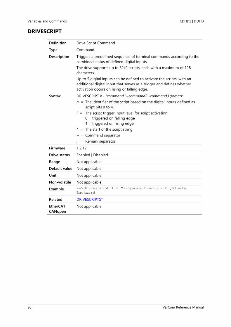
Variables and Commands CDHD2 | DDHD
96 VarCom Reference Manual
DRIVESCRIPT
Definition Drive Script Command
Type Command
Description Triggers a predefined sequence of terminal commands according to the
combined status of defined digital inputs.
The drive supports up to 32x2 scripts, each with a maximum of 128
characters.
Up to 5 digital inputs can be defined to activate the scripts, with an
additional digital input that serves as a trigger and defines whether
activation occurs on rising or falling edge.
Syntax DRIVESCRIPT n I "command1~command2~command3 ;remark
n = The identifier of the script based on the digital inputs defined as
script bits 0 to 4
l = The script trigger input level for script activation:
0 = triggered on falling edge
1 = triggered on rising edge
" = The start of the script string
~ = Command separator
; = Remark separator
Firmware 1.2.12
Drive status Enabled | Disabled
Range Not applicable
Default value Not applicable
Unit Not applicable
Non-volatile Not applicable
Example -->drivescript 1 2 "k~opmode 0~en~j -10 ;Slowly
Backward
Related DRIVESCRIPTST
EtherCAT
CANopen
Not applicable

CDHD2 | DDHD Variables and Commands
VarCom Reference Manual 97
DRIVESCRIPTDEL
Definition Drive Script Delay
Type Variable (R/W)
Description Gets/sets the time, after DRIVESCRIPT is triggered, before drive script
execution starts.
If the input script bit value changes before the delay time elapses, the
timer will be reset.
If DRIVESCRIPTDEL=0, the drive script is executed without any delay.
Syntax Read: DRIVESCRIPTDEL
Write: DRIVESCRIPTDEL<value>
Firmware 2.0.x
Drive status Enabled | Disabled
Range 0 to 10,000
Default value 0
Unit ms
Non-volatile Yes
Related DRIVESCRIPT
INMODE
EtherCAT
CANopen
Not applicable

Variables and Commands CDHD2 | DDHD
98 VarCom Reference Manual
DRIVESCRIPTST
Definition Drive Script Status
Type Variable (R)
Description Indicates the script that is being executed.
If no script is defined for the digital input combination, nothing will run.
Digital input definition:
INMODE 5=9 Script
INMODE 6=10 Script bit 0
INMODE 7=11 Script bit 1
INMODE 8=12 Script bit 2
INMODE 9=13 Script bit 3
INMODE 10=14 Script bit 4
Digital inputs 6-10 define which script to run.
Digital input 5 triggers script execution.
Syntax DRIVESCRIPTST
Firmware 1.2.12
Drive status Enabled | Disabled
Range Not applicable
Default value Not applicable
Unit Not applicable
Non-volatile No
Example -->drivescriptst
DriveScript [01][0] Start:J 100:DriveScript [01][0]
Stop:
-->
Related DRIVESCRIPT
INMODE
EtherCAT
CANopen
Not applicable
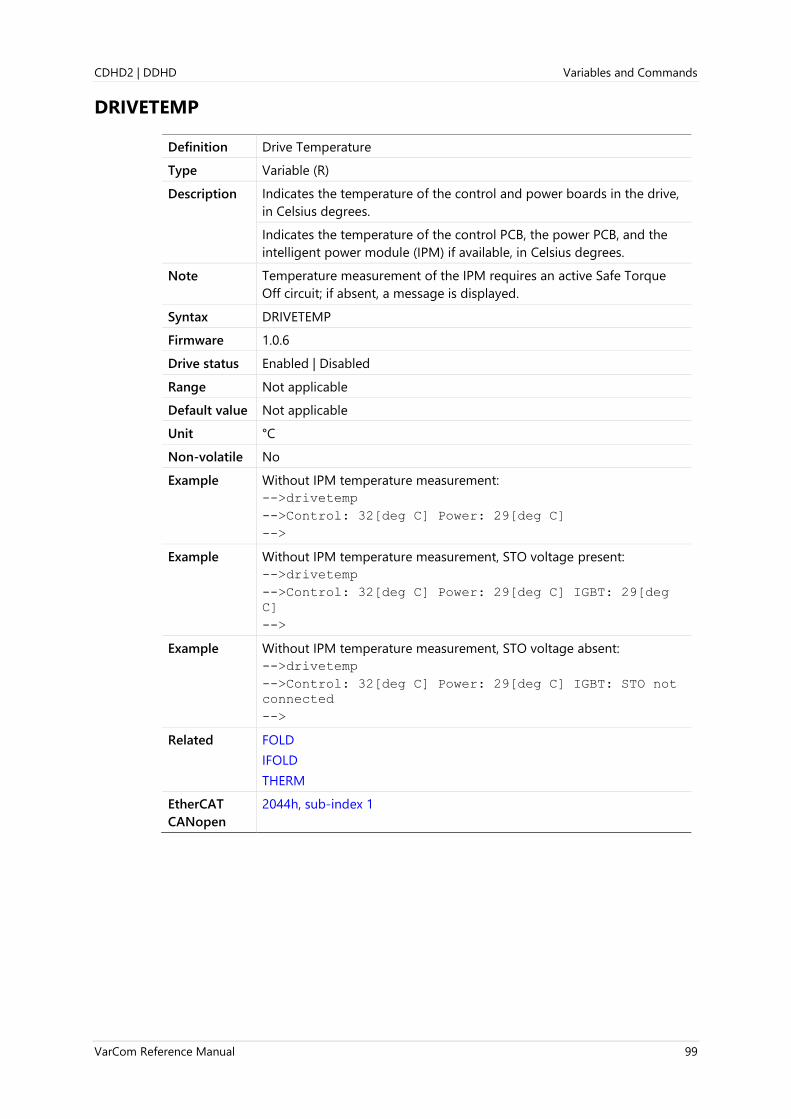
CDHD2 | DDHD Variables and Commands
VarCom Reference Manual 99
DRIVETEMP
Definition Drive Temperature
Type Variable (R)
Description Indicates the temperature of the control and power boards in the drive,
in Celsius degrees.
Indicates the temperature of the control PCB, the power PCB, and the
intelligent power module (IPM) if available, in Celsius degrees.
Note Temperature measurement of the IPM requires an active Safe Torque
Off circuit; if absent, a message is displayed.
Syntax DRIVETEMP
Firmware 1.0.6
Drive status Enabled | Disabled
Range Not applicable
Default value Not applicable
Unit °C
Non-volatile No
Example Without IPM temperature measurement:
-->drivetemp
-->Control: 32[deg C] Power: 29[deg C]
-->
Example Without IPM temperature measurement, STO voltage present:
-->drivetemp
-->Control: 32[deg C] Power: 29[deg C] IGBT: 29[deg
C]
-->
Example Without IPM temperature measurement, STO voltage absent:
-->drivetemp
-->Control: 32[deg C] Power: 29[deg C] IGBT: STO not
connected
-->
Related FOLD
IFOLD
THERM
EtherCAT
CANopen
2044h, sub-index 1

Variables and Commands CDHD2 | DDHD
100 VarCom Reference Manual
DUMP
Definition Dump Drive Parameter Values
Type Command
Description Returns the set of configuration parameters that defines the complete
functionality of the drive. The command can be used to backup the
configuration.
Note Some parameters, not intended for users, may appear in the list.
Do not attempt to manipulate parameters that are not described in
the product documentation or Help.
Syntax DUMP
Firmware 1.0.6
Drive status Enabled | Disabled
Range Not applicable
Default value Not applicable
Unit Not applicable
Non-volatile Not applicable
Related LOAD
SAVE
EtherCAT
CANopen
Not applicable

CDHD2 | DDHD Variables and Commands
VarCom Reference Manual 101
ECEMCYMODE
Definition EtherCAT Emergency Message Mode
Type Variable (R/W)
Description Defines whether or not EtherCAT emergency message is sent to the
master.
Syntax Read: ECEMCYMODE
Write: ECEMCYMODE <value>
Firmware 1.15.xx
Drive status Enabled | Disabled
Range 0 = EtherCAT emergency message is not sent to master
1 = EtherCAT emergency message is sent to master
Default value 1
Unit Not applicable
Non-volatile Yes
Related
EtherCAT
CANopen
Not applicable

Variables and Commands CDHD2 | DDHD
102 VarCom Reference Manual
ECHO
Definition Serial Communication Character Echo
Type Variable (R/W)
Description Enables/disables the serial port character echo. If echo is enabled,
characters received via the serial port are echoed back to the serial port
and displayed on the computer monitor.
ECHO 1 is required for proper operation of the graphic interface
software.
ECHO 0 will cause the graphic interface software to lose certain
functionalities. Use with caution.
Syntax Read: ECHO
Write: ECHO <value>
Firmware 1.0.6
Drive status Enabled | Disabled
Range 0 = Serial port echo disabled
1 = Serial port echo enabled
Default value Not applicable
Unit Not applicable
Non-volatile Yes
Related ADDR
MSGPROMPT
EtherCAT
CANopen
Not applicable
Panel P 6 0 0 3

CDHD2 | DDHD Variables and Commands
VarCom Reference Manual 103
ECMAPDEFAULT
Definition EtherCAT PDO Mapping Default
Type Command
Description Restores all PDO objects to default mapping.
Syntax ECMAPDEFAULT
Firmware 2.0.x
Drive status Disabled
Range Not applicable
Default value Not applicable
Unit Not applicable
Non-volatile Not applicable
Related
EtherCAT
CANopen
Not applicable

Variables and Commands CDHD2 | DDHD
104 VarCom Reference Manual
ECREADCOMMSTATE
Definition EtherCAT Read NMT State
Type Command
Description Used for reading the NMT state through serial communication.
Applicable only when COMMODE=1. If COMMODE=0, the command
returns -1.
Useful for diagnostics when using EtherCAT communication.
Syntax ECREADCOMMSTATE
Firmware 2.0.x
Drive status Enabled | Disabled
Range Possible values returned by ECREADCOMMSTATE:
0 = UNKNOWN
1 = INIT
2 = PREOP
3 = BOOTSTRAP
4 = SAFEOP
8 = OP
-1 = when COMMODE=0; non-EtherCAT drive
Default value Not applicable
Unit Not applicable
Non-volatile No
Related na
EtherCAT
CANopen
Not applicable

CDHD2 | DDHD Variables and Commands
VarCom Reference Manual 105
ECSENDSDO
Definition EtherCAT Read/Write SDO Value
Type Variable (R/W)
Description Used for reading and writing an SDO object, in hexadecimal format,
through serial communication.
Useful for diagnostics when using EtherCAT communication.
Applicable only when COMMODE=1.
Syntax Read: ECSENDSDO <sdo > <sub-index>
Write: ECSENDSDO <sdo> <sub-index> <value>
Firmware 2.0.x
Drive status Enabled | Disabled
Range sdo: any object in drive; hnnnn format
sub-index: according to object
value: according to object
Default value Not applicable
Unit Not applicable
Non-volatile No
Example -->ECSENDSDO h6073 0
3462
-->ECSENDSDO h6073 0 1
-->ECSENDSDO h6073 0
1
-->ECSENDSDO h6073 0
1
-->ECSENDSDO h6073 0 3462
-->ECSENDSDO h6073 0
3462
Related
EtherCAT
CANopen
Not applicable

Variables and Commands CDHD2 | DDHD
106 VarCom Reference Manual
ECZEROMAP
Definition EtherCAT PDO Mapping Zero
Type Command
Description Clears PDO mapping for all objects by nulling the value of every
mapping. Takes effect after SAVE and power cycle.
Syntax ECZEROMAP
Firmware 2.0.x
Drive status Disabled
Range Not applicable
Default value Not applicable
Unit Not applicable
Non-volatile Not applicable
Related
EtherCAT
CANopen
Not applicable

CDHD2 | DDHD Variables and Commands
VarCom Reference Manual 107
ELECTANGLE
Definition Electrical Position
Type Variable (R)
Description Indicates the electrical angle position in 16-bit resolution.
Syntax ELECTANGLE
Firmware 1.0.6
Drive status Enabled | Disabled
Range 0 to 65535
Default value Not applicable
Unit 65536/electrical cycle
Non-volatile No
Related MECHANGLE
MENCRES
MPHASE
PHASEFIND
EtherCAT
CANopen
2016h, sub-index 0

Variables and Commands CDHD2 | DDHD
108 VarCom Reference Manual
EN
Definition Software Enable Command
Type Command
Description Initiates a software enable of the drive. This command first attempts to
reset any existing fault conditions, then sets SWEN to 1. If both READY
and REMOTE have values of 1, the drive is in Active state.
The value of ACTIVE indicates whether the EN command successfully
enabled the drive.
Note When Gantry mode is active (GANTRYMODE>0), EN attempts to enable
both gantry drives. If one drive fails to enable, a fault will be issued.
Syntax EN
Firmware 1.0.6
Drive status Enabled | Disabled
Range Not applicable
Default value Not applicable
Unit Not applicable
Non-volatile Not applicable
Related ACTIVE
FLT
K
READY
REMOTE
ST
SWEN
Note ⚫ EN is the Software Enable command. It first attempts to clear any
latched faults; if successful, the drive becomes Ready for enabling.
When the drive is Ready and the Remote Enable (hardware) signal is
on, the drive is enabled.
⚫ READY (R) indicates whether a drive is ready to be enabled (waiting
for Remote Enable ON signal).
⚫ ACTIVE (R) indicates whether a drive is enabled.
EtherCAT
CANopen
Not applicable
Panel C 0 0 0 3 (toggle Enable/Disable)
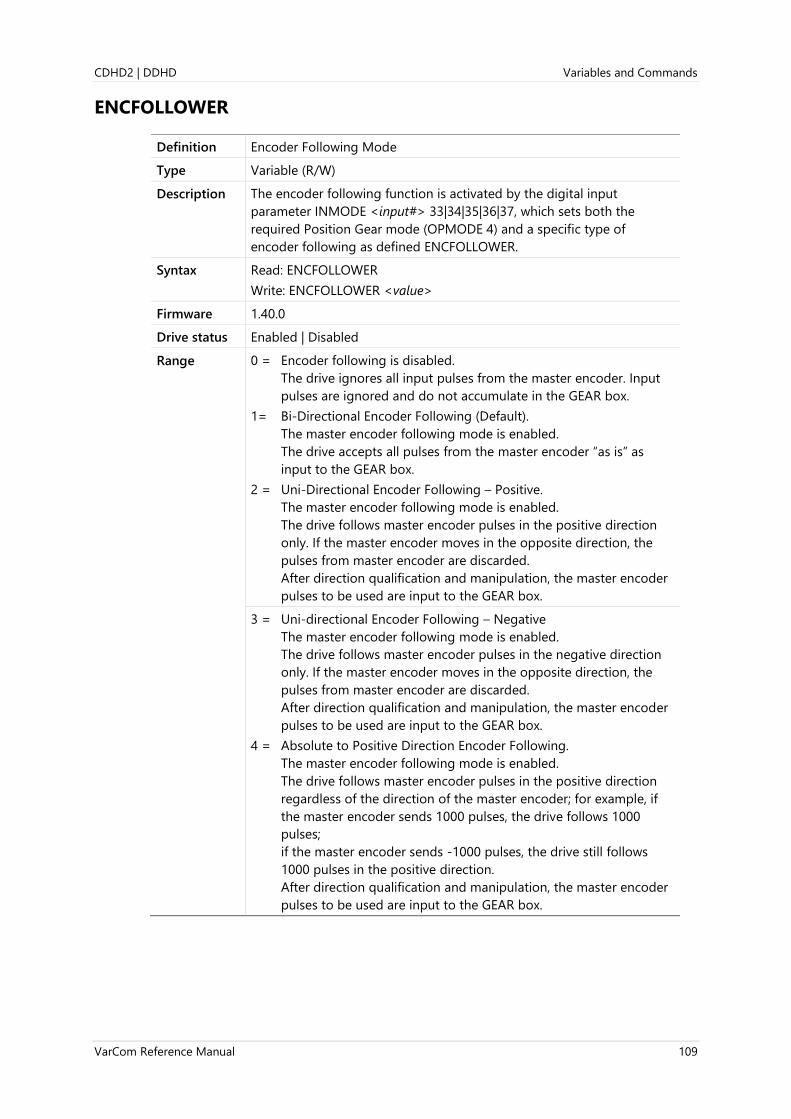
CDHD2 | DDHD Variables and Commands
VarCom Reference Manual 109
ENCFOLLOWER
Definition Encoder Following Mode
Type Variable (R/W)
Description The encoder following function is activated by the digital input
parameter INMODE <input#> 33|34|35|36|37, which sets both the
required Position Gear mode (OPMODE 4) and a specific type of
encoder following as defined ENCFOLLOWER.
Syntax Read: ENCFOLLOWER
Write: ENCFOLLOWER <value>
Firmware 1.40.0
Drive status Enabled | Disabled
Range 0 = Encoder following is disabled.
The drive ignores all input pulses from the master encoder. Input
pulses are ignored and do not accumulate in the GEAR box.
1= Bi-Directional Encoder Following (Default).
The master encoder following mode is enabled.
The drive accepts all pulses from the master encoder “as is” as
input to the GEAR box.
2 = Uni-Directional Encoder Following – Positive.
The master encoder following mode is enabled.
The drive follows master encoder pulses in the positive direction
only. If the master encoder moves in the opposite direction, the
pulses from master encoder are discarded.
After direction qualification and manipulation, the master encoder
pulses to be used are input to the GEAR box.
3 = Uni-directional Encoder Following – Negative
The master encoder following mode is enabled.
The drive follows master encoder pulses in the negative direction
only. If the master encoder moves in the opposite direction, the
pulses from master encoder are discarded.
After direction qualification and manipulation, the master encoder
pulses to be used are input to the GEAR box.
4 = Absolute to Positive Direction Encoder Following.
The master encoder following mode is enabled.
The drive follows master encoder pulses in the positive direction
regardless of the direction of the master encoder; for example, if
the master encoder sends 1000 pulses, the drive follows 1000
pulses;
if the master encoder sends -1000 pulses, the drive still follows
1000 pulses in the positive direction.
After direction qualification and manipulation, the master encoder
pulses to be used are input to the GEAR box.

Variables and Commands CDHD2 | DDHD
110 VarCom Reference Manual
5 = Absolute to Negative Direction Encoder Following.
The master encoder following mode is enabled.
The drive follows master encoder pulses in the negative direction
regardless of the direction of the master encoder; for example, if
the master encoder sends -1000 pulses, the drive follows -1000
pulses;
if the master encoder sends 1000 pulses, the drive still follows -
1000 pulses in the negative direction.
After direction qualification and manipulation, the master encoder
pulses to be used are input to the GEAR box.
Default value 1
Unit Not applicable
Non-volatile Yes
Related INMODE 33|34|35|36|37
EtherCAT
CANopen
Not applicable
Digital Input x
RS232
On/Off
Shaping Filters
GEAR Calculation
GEAR Limits
Position Controller
Qualifier
ENCFOLLOWER
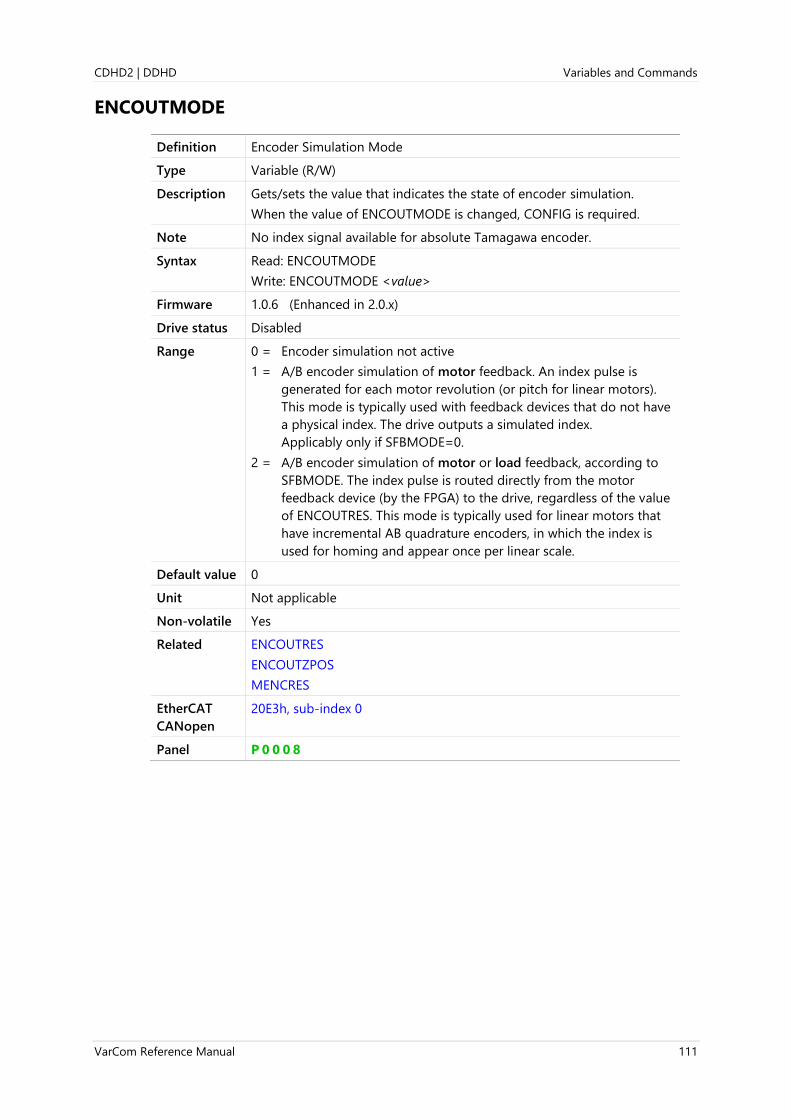
CDHD2 | DDHD Variables and Commands
VarCom Reference Manual 111
ENCOUTMODE
Definition Encoder Simulation Mode
Type Variable (R/W)
Description Gets/sets the value that indicates the state of encoder simulation.
When the value of ENCOUTMODE is changed, CONFIG is required.
Note No index signal available for absolute Tamagawa encoder.
Syntax Read: ENCOUTMODE
Write: ENCOUTMODE <value>
Firmware 1.0.6 (Enhanced in 2.0.x)
Drive status Disabled
Range 0 = Encoder simulation not active
1 = A/B encoder simulation of motor feedback. An index pulse is
generated for each motor revolution (or pitch for linear motors).
This mode is typically used with feedback devices that do not have
a physical index. The drive outputs a simulated index.
Applicably only if SFBMODE=0.
2 = A/B encoder simulation of motor or load feedback, according to
SFBMODE. The index pulse is routed directly from the motor
feedback device (by the FPGA) to the drive, regardless of the value
of ENCOUTRES. This mode is typically used for linear motors that
have incremental AB quadrature encoders, in which the index is
used for homing and appear once per linear scale.
Default value 0
Unit Not applicable
Non-volatile Yes
Related ENCOUTRES
ENCOUTZPOS
MENCRES
EtherCAT
CANopen
20E3h, sub-index 0
Panel P 0 0 0 8

Variables and Commands CDHD2 | DDHD
112 VarCom Reference Manual
ENCOUTRES
Definition Encoder Simulation Line Resolution
Type Variable (R/W)
Description Gets/sets the resolution, in number of lines, of the encoder simulation
output.
Use plus for positive direction; minus for negative direction.
When the value of ENCOUTRES is changed, CONFIG is required.
Notes ENCOUTRES is not applicable when ENCOUTMODE=0.
Changing the value of ENCOUTRES might cause the encoder simulation
to generate extra pulses.
Syntax Read: ENCOUTRES
Write: ENCOUTRES <value>
Firmware 1.0.6
Drive status Disabled
Range ±10000000, but not 0
Default value 2048
Unit If MOTORTYPE=0 (Rotary): lines per revolution (LPR)
If MOTORTYPE=2 (Linear): lines per pitch (LPP)
Non-volatile Yes
Related ENCOUTMODE
ENCOUTZPOS
MENCRES
EtherCAT
CANopen
20E4h, sub-index 0
Panel P 0 0 7

CDHD2 | DDHD Variables and Commands
VarCom Reference Manual 113
ENCOUTZPOS
Definition Encoder Simulation Index Position
Type Variable (R/W)
Description Gets/sets the index offset value of the encoder simulation output
(ENCOUTRES).
Note ENCOUTRES is applicable only when ENCOUTMODE=1.
Syntax Read: ENCOUTZPOS
Write: ENCOUTZPOS <value>
Firmware 1.0.6
Drive status Enabled | Disabled
Range 0 to 40000000
Default value 0
Unit Count
Non-volatile Yes
Related ENCOUTMODE
ENCOUTRES
MENCRES
EtherCAT
CANopen
20E5h, sub-index 0
Panel P 4 0 3 6

Variables and Commands CDHD2 | DDHD
114 VarCom Reference Manual
ENDATERRWRN
Definition EnDat Errors & Warnings Report
Type Variable (R)
Description Returns the error word and the warning word that were recorded on the
last EnDat initialization.
Syntax ENDATERRWRN
Firmware 2.15.x
Drive status Enabled | Disabled
Range Not applicable
Default value Not applicable
Unit Not applicable
Non-volatile No
Related
EtherCAT
CANopen
Not applicable

CDHD2 | DDHD Variables and Commands
VarCom Reference Manual 115
ERRCORACTIVENUM
Definition Error Correction Active Entries
Type Variable (R/W)
Description Gets/sets a value that defines the number of active entries in the error
correction table.
Up to 1000 entries can be defined (and active) in the error correction
table.
Syntax Read: ERRCORACTIVENUM
Write: ERRCORACTIVENUM <value>
Firmware 2.15.x
Drive status Disabled
Range 0 to 1000
Default value 0
Unit Not Applicable
Non-volatile Yes
Example --> ERRCORACTIVENUM
0
--> ERRCORSTARTOFF 10
Related ERRCOREN
EtherCAT
CANopen
2219h, sub-index 0

Variables and Commands CDHD2 | DDHD
116 VarCom Reference Manual
ERRCOREN
Definition Error Correction Request to Activate
Type Variable (R/W)
Description Gets/sets a value that indicates a user request to activate or deactivate
the error correction function.
Note The actual state of the error correction function is reported by
ERRCORST.
Syntax Read: ERRCOREN
Write: ERRCOREN <value>
Firmware 2.15.x
Drive status Disabled
Range 0 = User request to activate the error correction function.
1 = User request to deactivate the error correction function.
Default value 0
Unit Not Applicable
Non-volatile Yes
Related ERRCORACTIVENUM
ERRCORFAILINDEX
ERRCORINDEX
ERRCORINTERVAL
ERRCORRESET
ERRCORSETINDEX
ERRCORST
ERRCORSTARTOFF
ERRCORSTARTPOS
ERRCORUNITS
EtherCAT
CANopen
221Fh, sub-index 0

CDHD2 | DDHD Variables and Commands
VarCom Reference Manual 117
ERRCORFAILINDEX
Definition Error Correction Index Failed
Type Variable (R)
Description Indicates the index of the error correction table entry that failed due to
an invalid error size.
Error size must not exceed a maximum value of 1 (degree for rotary
units/ millimeters for linear units).
Syntax ERRCORFAILINDEX
Firmware 2.15.x
Drive status Enabled | Disabled
Range 1 to 1000
Default value 0
Unit Not applicable
Non-volatile No
Example --> ERRCORFAILINDEX
-1
--> ERRCORFAILINDEX
921
Related ERRCOREN
EtherCAT
CANopen
2222h, sub-index 0

Variables and Commands CDHD2 | DDHD
118 VarCom Reference Manual
ERRCORINDEX
Definition Error Correction Index
Type Variable (R)
Description Indicates the index of the error correction table entry whose value is
currently added to PFB.
Syntax ERRCORINDEX
Firmware 2.15.x
Drive status Enabled | Disabled
Range Not applicable
Default value 0
Unit Not applicable
Non-volatile No
Example --> ERRCORINDEX
12
--> ERRCORINDEX
921
Related ERRCOREN
EtherCAT
CANopen
221Ch, sub-index 0

CDHD2 | DDHD Variables and Commands
VarCom Reference Manual 119
ERRCORINTERVAL
Definition Error Correction Intervals
Type Variable (R/W)
Description Gets/sets the distance between the positions at which the errors are
measured and added to the correction table.
Syntax Read: ERRCORINTERVAL
Write: ERRCORINTERVAL <value>
Firmware 2.15.x
Drive status Disable
Range ±(231 -1)
Default value 10000 [default µm]
Unit According to ERRCORUNITS
Non-volatile Yes
Example --> ERRCORINTERVAL
10
--> ERRCORINTERVAL 100
Related ERRCOREN
EtherCAT
CANopen
221Bh, sub-index 0

Variables and Commands CDHD2 | DDHD
120 VarCom Reference Manual
ERRCORRESET
Definition Error Correction Reset Parameters
Type Command
Description Used to reset all error correction parameters and table entries to their
default values.
Reset occurs when ERRCORRESET is set to 1.
Syntax ERRCORRESET 1
Firmware 2.15.x
Drive status Disabled
Range Not Applicable
Default value Not Applicable
Unit Not Applicable
Non-volatile Not Applicable
Related ERRCOREN
EtherCAT
CANopen
221Eh, sub-index 0

CDHD2 | DDHD Variables and Commands
VarCom Reference Manual 121
ERRCORSETINDEX
Definition Error Correction Set Index Value
Type Variable (R/W)
Description Gets/sets a correction value for a specific entry in the correction table.
Syntax ERRCORSETINDEX <index>
ERRCORSETINDEX <index> <value>
Firmware 2.15.x
Drive status Disabled
Range <index> = 0 to 999
<value> = ±(231 - 1)
Default value 0
Unit <index> = Not applicable
<value> = As defined by ERRCORUNITS
Non-volatile Yes
Example --> ERRCORSETINDEX 1
0.3
--> ERRMAXCORVAL 1 0.4
Related ERRCOREN
EtherCAT
CANopen
221Dh, sub-index 0

Variables and Commands CDHD2 | DDHD
122 VarCom Reference Manual
ERRCORST
Definition Error Correction Status
Type Variable (R)
Description Indicates the state of the error correction function after a user request
(ERRCOREN) has been issued.
Syntax ERRCORST
Firmware 2.15.x
Drive status Enabled | Disabled
Range 0 = Error correction inactive.
1 = Error correction configured. Ready for activation.
2 = Error correction active.
3 = Error correction configured. Homing required before activation.
4 = Calculation and verification of error correction values in progress.
-3 = Error correction inactive. Conflicting MOTORTYPE and
ERRCORUNITS (rotary units on linear motor).
-2 = Error correction inactive. Start position offset out of range.
-1 = Error correction inactive. Error correction value exceeds limit.
Default value 0
Unit Not Applicable
Non-volatile No
Related ERRCOREN
EtherCAT
CANopen
2220h, sub-index 0

CDHD2 | DDHD Variables and Commands
VarCom Reference Manual 123
ERRCORSTARTOFF
Definition Error Correction Start Index Offset
Type Variable (R/W)
Description Gets/sets a value that defines the offset to the first active entry at the
error correction table.
ERRCORSTARTOFF enables the use of two or more sets of error
correction data within one error correction table. This is useful, for
example, when error values may change due to environmental
conditions, such as ambient temperature levels.
Syntax Read: ERRCORSTARTOFF
Write: ERRCORSTARTOFF <value>
Firmware 2.15.x
Drive status Disabled
Range 0 to 999
Default value 0
Unit Not Applicable
Non-volatile Yes
Example --> ERRCORSTARTOFF
0
--> ERRCORSTARTOFF 107
Related ERRCOREN
EtherCAT
CANopen
2218h, sub-index 0
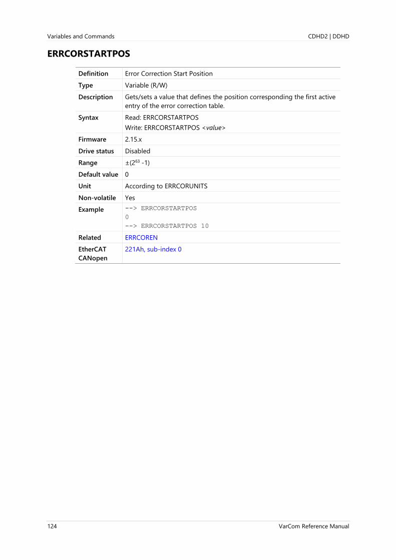
Variables and Commands CDHD2 | DDHD
124 VarCom Reference Manual
ERRCORSTARTPOS
Definition Error Correction Start Position
Type Variable (R/W)
Description Gets/sets a value that defines the position corresponding the first active
entry of the error correction table.
Syntax Read: ERRCORSTARTPOS
Write: ERRCORSTARTPOS <value>
Firmware 2.15.x
Drive status Disabled
Range ±(263 -1)
Default value 0
Unit According to ERRCORUNITS
Non-volatile Yes
Example --> ERRCORSTARTPOS
0
--> ERRCORSTARTPOS 10
Related ERRCOREN
EtherCAT
CANopen
221Ah, sub-index 0

CDHD2 | DDHD Variables and Commands
VarCom Reference Manual 125
ERRCORUNITS
Definition Error Correction Units
Type Variable (R/W)
Description Gets/sets a value that defines the units of the error position data
delivered by the error correction table.
Also defines the units of ERRCORSTARTPOS.
Syntax Read: ERRCORUNITS
Write: ERRCORUNITS <value>
Firmware 2.15.x
Drive status Disabled
Range 0 = mm
1 = µm
2 = degrees
3 = µdegrees
4 = counts
Default value 0
Unit Not Applicable
Non-volatile Yes
Example --> ERRCORUNITS
1
--> ERRCORUNITS 0
Related ERRCOREN
EtherCAT
CANopen
2223h, sub-index 0

Variables and Commands CDHD2 | DDHD
126 VarCom Reference Manual
ESTOPILIM
Definition Emergency or Controlled Stop Current Limit
Type Variable (R/W)
Description Gets/sets the current limit during an emergency or controlled stop
(expressed as factor of ILIM).
Syntax Read: ESTOPILIM
Write: ESTOPILIM <value>
Firmware 1.2.12
Drive status Enabled | Disabled
Range 0.001 to 1
Default value 1.000 (factor of ILIM)
Unit Not applicable
Non-volatile Yes
Related DISMODE
ILIM
EtherCAT
CANopen
208Dh, sub-index 0
Panel P 7 1 0 5
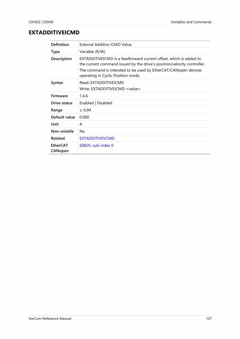
CDHD2 | DDHD Variables and Commands
VarCom Reference Manual 127
EXTADDITIVEICMD
Definition External Additive ICMD Value
Type Variable (R/W)
Description EXTADDITIVEICMD is a feedforward current offset, which is added to
the current command issued by the drive’s position/velocity controller.
The command is intended to be used by EtherCAT/CANopen devices
operating in Cyclic Position mode.
Syntax Read: EXTADDITIVEICMD
Write: EXTADDITIVEICMD <value>
Firmware 1.4.6
Drive status Enabled | Disabled
Range ± ILIM
Default value 0.000
Unit A
Non-volatile No
Related EXTADDITIVEVCMD
EtherCAT
CANopen
60B2h, sub-index 0

Variables and Commands CDHD2 | DDHD
128 VarCom Reference Manual
EXTADDITIVEVCMD
Definition External Additive VCMD Value
Type Variable (R/W)
Description EXTADDITIVEVCMD is a feedforward current offset, which is added to
the current command issued by the drive’s position/velocity controller.
Note EXTADDITIVEVCMD is applicable only to the linear position controller
(POSCONTROLMODE 0).
Syntax Read: EXTADDITIVEVCMD
Write: EXTADDITIVEVCMD <value>
Firmware 1.4.6
Drive status Enabled | Disabled
Range ± VLIM
Default value 0.000
Unit If MOTORTYPE 0 (Rotary):
If UNITSROTVEL 0 = rps
If UNITSROTVEL 1 = rpm
If UNITSROTVEL 2 = deg/s
If MOTORTYPE 2 (Linear):
UNITSLINVEL 1 = mm/s
Non-volatile No
Related EXTADDITIVEICMD
EtherCAT
CANopen
60B1h, sub-index 0
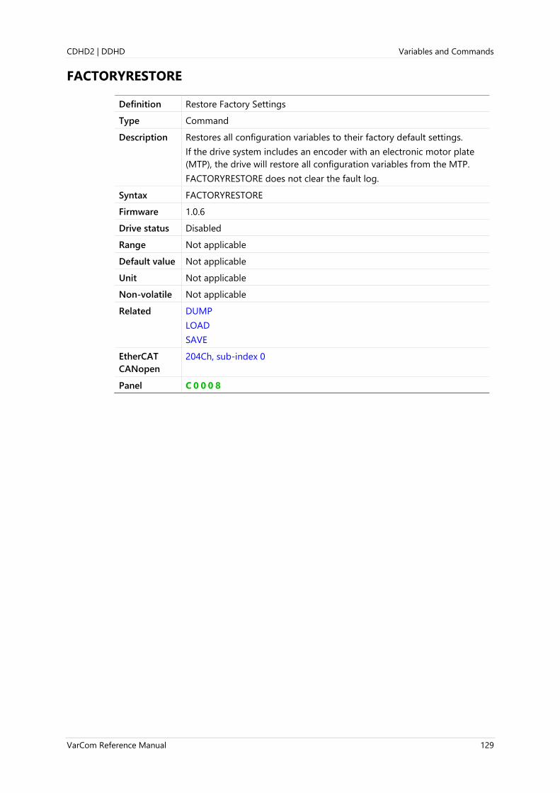
CDHD2 | DDHD Variables and Commands
VarCom Reference Manual 129
FACTORYRESTORE
Definition Restore Factory Settings
Type Command
Description Restores all configuration variables to their factory default settings.
If the drive system includes an encoder with an electronic motor plate
(MTP), the drive will restore all configuration variables from the MTP.
FACTORYRESTORE does not clear the fault log.
Syntax FACTORYRESTORE
Firmware 1.0.6
Drive status Disabled
Range Not applicable
Default value Not applicable
Unit Not applicable
Non-volatile Not applicable
Related DUMP
LOAD
SAVE
EtherCAT
CANopen
204Ch, sub-index 0
Panel C 0 0 0 8

Variables and Commands CDHD2 | DDHD
130 VarCom Reference Manual
FASTSTOENABLE
Definition Fast STO-Enable Function
Type Variable (R/W)
Description Defines whether the Fast STO Enable function is activated.
Applicable only for DDHD and STO-certified CDHD2 drives (-ST
models) – drives capable of AC-loss detection.
When Fast STO Enable is active, the drive can be reenabled within
150 ms, rather than 800 ms, once the STO condition is cleared.
Syntax Read: FASTOENABLE
Write: FASTOENABLE <value>
Firmware 1.20.6
Drive status Enabled | Disabled
Range 0 = Not activated
1 = Activated
Default value 0, if applicable
Unit Not applicable
Non-volatile No
Related
EtherCAT
CANopen
Not applicable

CDHD2 | DDHD Variables and Commands
VarCom Reference Manual 131
FBGDS
Definition Fieldbus (EtherCAT/CANopen) Gear Driving Shaft Scaling
Type Variable (R/W)
Description The EtherCAT/CANopen gear ratio driving shaft revolution scaling factor
(object 6091h sub-index 2).
Syntax Read: FBGDS
Write: FBGDS <value>
Firmware 1.2.12
Drive status Enabled | Disabled
Range 1 to 4294967295
Default value 1
Unit Not applicable
Non-volatile Yes
Related FBGMS
FBITIDX
FBSCALE
EtherCAT
CANopen
6091h, sub-index 2
Panel P 6 0 0 6

Variables and Commands CDHD2 | DDHD
132 VarCom Reference Manual
FBGMS
Definition Fieldbus (EtherCAT/CANopen) Gear Motor Shaft Scaling
Type Variable (R/W)
Description The EtherCAT/CANopen gear ratio motor shaft revolution scaling factor
(object 6091h sub-index 1)
Syntax Read: FBGMS
Write: FBGMS <value>
Firmware 1.2.12
Drive status Enabled | Disabled
Range 1 to 4294967295
Default value 1
Unit Not applicable
Non-volatile Yes
Related FBGDS
FBITIDX
FBSCALE
EtherCAT
CANopen
6091h, sub-index 1
Panel P 6 0 0 7

CDHD2 | DDHD Variables and Commands
VarCom Reference Manual 133
FBINTTYPE
Definition Fieldbus (EtherCAT/CANopen) Interpolation Type
Type Variable (R/W)
Description The EtherCAT/CANopen type of interpolation.
If the linear interpolation is selected, the interpolation data given in the
interpolation data record is used.
If a manufacturer-specific type of interpolation is selected, the
corresponding interpolation data record must be implemented in the
manufacturer-specific profile area of the object dictionary.
When operating in EtherCAT/CANopen Cyclic Synchronous Position
mode, the interpolation value can be 0, 1, 2 or 3.
When operating in EtherCAT/CANopen Cyclic Synchronous Velocity or
Cyclic Synchronous Torque mode, interpolation is always linear.
Syntax Read: FBINTTYPE
Write: FBINTTYPE <value>
Firmware 2.0.x
Drive status Enabled | Disabled
Range 0 = Linear interpolation.
1= Cubic interpolation with position and velocity.
2= Cubic interpolation with position only – strict. Forces the
interpolated path to pass via the original position commands sent
by the controller; this may cause an abrupt velocity profile when
velocity changes.
3= Cubic interpolation with position only – loose. Does not force the
interpolated path to pass via the original position commands sent
by the controller, thus resulting in a smoother velocity profile.
Default value 0
Unit Not applicable
Non-volatile Yes
Related
EtherCAT
CANopen
60C0h, sub-index 0

Variables and Commands CDHD2 | DDHD
134 VarCom Reference Manual
FBITIDX
Definition Fieldbus (EtherCAT/CANopen) Interpolation Time Index
Type Variable (R/W)
Description The interpolation time index for the EtherCAT/CANopen cycle time
calculations.
Note The cycle time in the controller and the cycle time in the drive (FBITIDX,
FBITPRD) must be identical.
Syntax Read: FBITIDX
Write: FBITIDX <value>
Firmware 1.2.12
Drive status Disabled
Range -128 to 63
Default value -3
Unit Not applicable
Non-volatile Yes
Related FBGDS
FBGMS
FBITIDX
FBITPRD
FBSCALE
EtherCAT
CANopen
60C2h, sub-index 2
Panel P 6 0 0 8

CDHD2 | DDHD Variables and Commands
VarCom Reference Manual 135
FBITPRD
Definition Fieldbus (EtherCAT/CANopen) Interpolation Time
Type Variable (R/W)
Description The interpolation time period for the EtherCAT/CANopen cycle time
calculations.
Note The cycle time in the controller and the cycle time in the drive (FBITIDX,
FBITPRD) must be identical.
Syntax Read: FBITPRD
Write: FBITPRD <value>
Firmware 1.2.12
Drive status Disabled
Range 1 to 255
Default value 2
Unit Not applicable
Non-volatile Yes
Related CANBITRATE
FBGDS
FBITIDX
FBITPRD
EtherCAT
CANopen
60C2h, sub-index 1
Panel P 6 0 0 9

Variables and Commands CDHD2 | DDHD
136 VarCom Reference Manual
FBPLIGNORE
Definition Fieldbus (EtherCAT/CANopen) Fault Response
Type Variable (R/W)
Description Bit 0: Defines whether the drive responds to the EtherCAT/CANopen
packet loss fault.
Bit 1: Defines whether the drive responds to the EtherCAT/CANopen
controller interpolation cycle time not matching drive interpolation
time.
Syntax Read: FBPLIGNORE
Write: FBPLIGNORE <value>
Firmware 1.4.4
Drive status Disabled
Range Bit 0:
0 = Drive responds to fault
1 = Drive ignores fault
Bit 1:
0 = Drive responds to interpolation time fault
1 = Drive ignores interpolation time fault
Default value 0
Unit Not applicable
Non-volatile No
Related FBSCALE
EtherCAT
CANopen
Not applicable
Panel P 6 0 1 1

CDHD2 | DDHD Variables and Commands
VarCom Reference Manual 137
FBSCALE
Definition Fieldbus (EtherCAT/CANopen) Unit Scaling
Type Variable (R/W)
Description EtherCAT/CANopen unit scaling for internal counts. Defines the number
of bits of a 32-bit position that are equivalent to a number of
revolutions.
Syntax Read: FBSCALE
Write: FBSCALE <value>
Firmware 1.2.12
Drive status Enabled | Disabled
Range 0 to 20
Default value 12
Unit Not applicable
Non-volatile Yes
Related FBPLIGNORE
MENCRES
EtherCAT
CANopen
200Fh, sub-index 0
Panel P 6 0 1 1

Variables and Commands CDHD2 | DDHD
138 VarCom Reference Manual
FBSYNCACT
Definition Fieldbus (EtherCAT/CANopen) Actual Sync Time
Type Variable (R)
Description Returns the (actual) measured time between two fieldbus connection
synchronization signals, in milliseconds.
Syntax FBSYNCACT
Firmware 2.0.x
Drive status Enabled | Disabled
Range Not applicable
Default value Not applicable
Unit ms
Non-volatile No
Example --> FBSYNCACT
1 [ms]
Related
EtherCAT
CANopen
Not applicable

CDHD2 | DDHD Variables and Commands
VarCom Reference Manual 139
FEEDBACKBR
Definition Communication Feedback Baud Rate
Type Variable (R/W)
Description Gets/sets the baud rate of certain feedback devices.
FEEDBACKBR values other than the default may be set only if the
configured encoder requires the change (such as Nikon with 4 M baud
communication rate), or if the configured encoder communication rate
is determined by the drive (clocked encoders such as EnDat and BiSS-
C).
When using a FEEDBACKBR value other than the default with clocked
encoders, verify that the selected baud rate matches the encoder query
rate
By default, FEEDBACKBR = 0, meaning feedback devices are
automatically set to the following baud rates:
Nikon 17-bit and 20-bit
Absolute Encoder; single/multi-turn
FEEDBACKTYPE 4 2.5 MBd
Tamagawa 17-bit and 23-bit
Absolute Encoder; multi- turn
FEEDBACKTYPE 6 2.5 MBd
Tamagawa 17-bit and 23-bit
Absolute Encoder; single turn
FEEDBACKTYPE 7 2.5 MBd
EnDat 2.x Communication Only FEEDBACKTYPE 11 2 MBd
sensAR FEEDBACKTYPE 12 2.5 MBd
Sankyo Absolute Rotary Encoder FEEDBACKTYPE 14 2.5 MBd
Syntax Read: FEEDBACKBR
Write: FEEDBACKBR <value>
Firmware 1.15.xx
Drive status Disabled
Range 0 to 5000
Default value 0
Unit kBd
Non-volatile Yes
Example --> FEEDBACKBR 4000 Sets the baud rate to 4 MBd
Related FEEDBACKTYPE
EtherCAT
CANopen
Not applicable

Variables and Commands CDHD2 | DDHD
140 VarCom Reference Manual
FEEDBACKTYPE
Definition Feedback Type
Type Variable (R/W)
Description Gets/set the motor feedback type.
When the value of FEEDBACKTYPE is changed, CONFIG is required.
If FEEDBACKTYPE=0 at power-up, the drive attempts to detect the
feedback device that is connected the drive, in the following sequence:
1. The drive first attempts to communicate with a sensAR feedback. If
successful, FEEDBACKTYPE will be set according to the device and the
drive will attempt to read MTP data from the encoder. If data is read
successfully, MTPMODE will be set to 3; if not, MTPMODE will be set
to 0.
2. If communication with sensAR fails, the drive will then attempt to
communicate with a HIPERFACE feedback device (FEEDBACKTYPE 3,
MENCTYPE 10). If communication is established, the drive will attempt
to read MTP data from the encoder. If data is read successfully,
MTPMODE will be set to 3; if not, MTPMODE will be set to 0.
3. If communication with HIPERFACE fails, the drive will then attempt to
communicate with a Tamagawa single turn encoder (associated with
Welling motors). If communication is established, the drive will attempt
to read MTP data from the encoder. If data is read successfully,
MTPMODE will be set to 4; if not, MTPMODE will be set to 0.
4. If communication with Tamagawa single turn encoder fails, the drive
will report a fault: Feedback type auto-detection failed. In addition,
FEEDBACKTYPE and MTPMODE will both be set to 0.
Syntax Read: FEEDBACKTYPE
Write: FEEDBACKTYPE <value>
Firmware 1.0.6
Drive status Disabled
Range FEEDBACKTYPE MENCTYPE
Resolver 1 Not applicable (0)
Incremental Encoder; A, B and
index channels, and Halls
(A/B/Z/H)
2 0
Incremental Encoder; A/B/Z
commutation initialization by
PHASEFIND command
2 1
Incremental Encoder; A/B/Z
commutation initialization by
ENABLE or PHASEFIND command
2 2
Incremental Encoder; A/B
commutation initialization by
PHASEFIND command
2 3
Incremental Encoder; A/B
commutation initialization by
ENABLE or PHASEFIND command
2 4
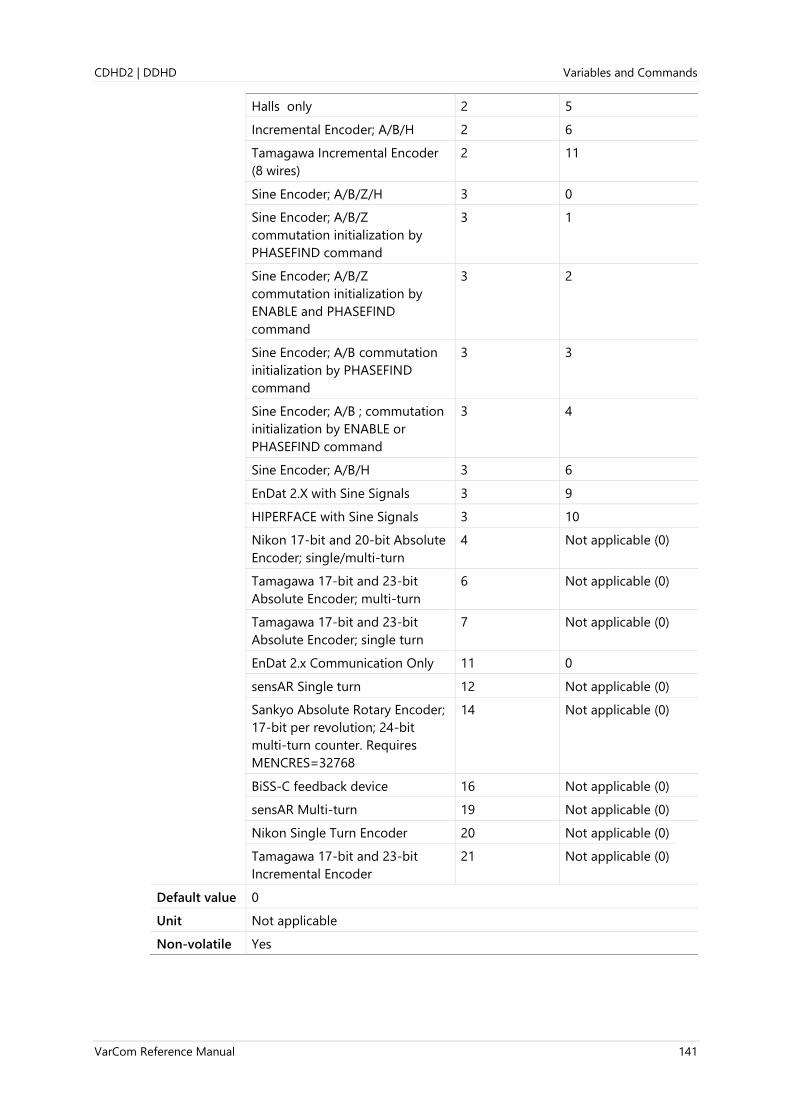
CDHD2 | DDHD Variables and Commands
VarCom Reference Manual 141
Halls only 2 5
Incremental Encoder; A/B/H 2 6
Tamagawa Incremental Encoder
(8 wires)
2 11
Sine Encoder; A/B/Z/H 3 0
Sine Encoder; A/B/Z
commutation initialization by
PHASEFIND command
3 1
Sine Encoder; A/B/Z
commutation initialization by
ENABLE and PHASEFIND
command
3 2
Sine Encoder; A/B commutation
initialization by PHASEFIND
command
3 3
Sine Encoder; A/B ; commutation
initialization by ENABLE or
PHASEFIND command
3 4
Sine Encoder; A/B/H 3 6
EnDat 2.X with Sine Signals 3 9
HIPERFACE with Sine Signals 3 10
Nikon 17-bit and 20-bit Absolute
Encoder; single/multi-turn
4 Not applicable (0)
Tamagawa 17-bit and 23-bit
Absolute Encoder; multi-turn
6 Not applicable (0)
Tamagawa 17-bit and 23-bit
Absolute Encoder; single turn
7 Not applicable (0)
EnDat 2.x Communication Only 11 0
sensAR Single turn 12 Not applicable (0)
Sankyo Absolute Rotary Encoder;
17-bit per revolution; 24-bit
multi-turn counter. Requires
MENCRES=32768
14 Not applicable (0)
BiSS-C feedback device 16 Not applicable (0)
sensAR Multi-turn 19 Not applicable (0)
Nikon Single Turn Encoder 20 Not applicable (0)
Tamagawa 17-bit and 23-bit
Incremental Encoder
21 Not applicable (0)
Default value 0
Unit Not applicable
Non-volatile Yes

Variables and Commands CDHD2 | DDHD
142 VarCom Reference Manual
Related MENCRES
MENCTYPE
MOTORTYPE
MRESPOLES
EtherCAT
CANopen
204Dh, sub-index 0
Panel P 2 0 0 0

CDHD2 | DDHD Variables and Commands
VarCom Reference Manual 143
FILTEXTHZ1
Definition Velocity Loop Second Filter Parameter 1
Type Variable (R/W)
Description A multi-function parameter for setting the output filter of the velocity
controller. FILTEXTMODE defines its functionality.
Note This parameter is applicable only in linear control loop.
Syntax Read: FILTEXTHZ1
Write: FILTEXTHZ1 <value>
Firmware 2.15.x
Drive status Enabled | Disabled
Range 1 to 3500
Default value 1000
Unit Hz
Non-volatile Yes
Related FILTEXTHZ2
FILTEXTMODE
EtherCAT
CANopen
2212h, sub-index 0

Variables and Commands CDHD2 | DDHD
144 VarCom Reference Manual
FILTEXTHZ2
Definition Velocity Loop Second Filter Parameter 2
Type Variable (R/W)
Description A multi-function parameter for setting the output filter of the
velocity controller. FILTEXTMODE defines its functionality.
Note This parameter is applicable only in linear control loop.
Syntax Read: FILTEXTHZ2
Write: FILTEXTHZ2 <value>
Firmware 2.15.x
Drive status Enabled | Disabled
Range 1 to 3500
Default value 2000
Unit Hz
Non-volatile Yes
Related FILTEXTHZ1
FILTEXTMODE
EtherCAT
CANopen
2213h, sub-index 0

CDHD2 | DDHD Variables and Commands
VarCom Reference Manual 145
FILTEXTMODE
Definition Velocity Loop Second Filter Mode
Type Variable (R/W)
Description Gets/sets the value that defines the function of an additional filter for
the velocity control loop.
FILTEXTMODE is useful when two filters are needed.
Note This parameter is applicable only in linear control loop.
Syntax Read: FILTEXTMODE
Write: FILTEXTMODE <value>
Firmware 2.15.x
Drive status Enabled | Disabled
Range 0 = Transparent feed through; no filtering.
1 = First order low pass filter; sets FILTEXTHZ1 as corner frequency.
2 = Double first order low pass filter; sets FILTEXTHZ1 and FILTEXTHZ2
as corner frequencies.
3 = Notch filter; sets FILTEXTHZ2 as notch center frequency and
FILTEXTHZ1 as notch frequency width.
4 = Reserved
5 = Reserved
6 = User defined polynomial filter; sets VFEXT.
7 = Advanced notch filter. This filter has a phase change limited to 50;
sets FILTEXTHZ1 as notch frequency width and FILTEXTHZ2 as
notch center frequency.
Default value 0
Unit Not applicable
Non-volatile Yes
Related FILTEXTHZ1
FILTEXTHZ2
VFEXT
EtherCAT
CANopen
2211h, sub-index 0

Variables and Commands CDHD2 | DDHD
146 VarCom Reference Manual
FILTHZ1
Definition Velocity Loop First Filter Parameter 1
Type Variable (R/W)
Description Velocity loop output filter first parameter.
A multi-functional parameter for setting the output filter of the velocity
controller. FILTMODE defines its functionality.
Note This parameter is applicable only in linear control loop.
Syntax Read: FILTHZ1
Write: FILTHZ1 <value>
Firmware 1.0.6
Drive status Enabled | Disabled
Range 1 to 3500
Default value 1000
Unit Hz
Non-volatile Yes
Related FILTHZ2
FILTMODE
EtherCAT
CANopen
204Eh, sub-index 0
Panel P 1 2 0 4

CDHD2 | DDHD Variables and Commands
VarCom Reference Manual 147
FILTHZ2
Definition Velocity Loop Output Filter Parameter 2
Type Variable (R/W)
Description Velocity loop output filter second parameter.
A multi-function parameter for setting the output filter of the velocity
controller. FILTMODE defines its functionality.
Note This parameter is applicable only in linear control loop.
Syntax Read: FILTHZ2
Write: FILTHZ2 <value>
Firmware 1.0.6
Drive status Enabled | Disabled
Range 1 to 3500
Default value 2000
Unit Hz
Non-volatile Yes
Related FILTHZ1
FILTMODE
EtherCAT
CANopen
204Fh, sub-index 0
Panel P 1 2 0 5

Variables and Commands CDHD2 | DDHD
148 VarCom Reference Manual
FILTMODE
Definition Velocity Loop First Filter Mode
Type Variable (R/W)
Description Gets/sets the value that defines the function of the (first) filter for the
velocity control loop.
Note This parameter is applicable only in linear control loop.
Syntax Read: FILTMODE
Write: FILTMODE <value>
Firmware 1.0.6
Drive status Enabled | Disabled
Range 0 = Transparent feed through; no filtering.
1 = First order low pass filter; sets FILTHZ1 as corner frequency.
2 = Double first order low pass filter; sets FILTHZ1 and FILTHZ2 as
corner frequencies.
3 = Notch filter; sets FILTHZ2 as notch center frequency and FILTHZ1
as notch frequency width.
4 = Not in use (as of Firmware 2.15.x).
5 = Not in use (as of Firmware 2.15.x).
6 = User defined polynomial filter; sets VF.
7 = Advanced notch filter. This filter has a phase change limited to 50;
sets FILTHZ2 as notch center frequency and FILTHZ1 as notch
frequency width. (Added in FW 2.15.x.)
Default value 2
Unit Not applicable
Non-volatile Yes
Related FILTHZ1
FILTHZ2
VELCONTROLMODE
VF
EtherCAT
CANopen
2050h, sub-index 0
Panel P 1 2 0 3

CDHD2 | DDHD Variables and Commands
VarCom Reference Manual 149
FLT
Definition Print Faults
Type Variable (R)
Description Returns a list of faults latched by the drive. Faults remain latched until
cleared by CLEARFAULTS or EN, provided that the fault condition has
been removed.
Syntax FLT
Firmware 1.0.6
Drive status Enabled | Disabled
Range Not applicable
Default value Not applicable
Unit Not applicable
Non-volatile No
Related DISMODE
FLTHIST
WRN
EtherCAT
CANopen
603Fh, sub-index 0

Variables and Commands CDHD2 | DDHD
150 VarCom Reference Manual
FLTHIST
Definition Fault History
Type Command
Description Returns the contents of the fault buffer.
The drive transmits the fault history to the serial port. The most recent
fault is sent first. A time stamp in the format of hours:minutes:seconds is
displayed along with each fault, indicating the time at which the fault
occurred.
The fault buffer can contain up to 40 faults. Once the buffer is full, the
oldest fault is automatically removed whenever a new fault is added.
Syntax FLTHIST
Firmware 1.0.6
Drive status Enabled | Disabled
Range Not applicable
Default value Not applicable
Unit Not applicable
Non-volatile No
Example --> flthist
2:28:55 A/B Line Break
2:28:55 Illegal Halls
2:28:49 Illegal Halls
-->
Related FLT
WRN
EtherCAT
CANopen
Not applicable

CDHD2 | DDHD Variables and Commands
VarCom Reference Manual 151
FOLD
Definition Drive Foldback Status
Type Variable (R)
Description Indicates whether the drive foldback limit (IFOLD) has dropped below
the application’s current limits (ILIM).
Syntax FOLD
Firmware 1.0.6
Drive status Enabled | Disabled
Range 0 = Foldback limit above ILIM
1 = Foldback limit below ILIM
Default value Not applicable
Unit Not applicable
Non-volatile No
Related DICONT
IFOLD
IFOLDFTHRESH
IFOLDWTHRESH
ILIM
EtherCAT
CANopen
2051h, sub-index 0
Panel P 7 0 0 2

Variables and Commands CDHD2 | DDHD
152 VarCom Reference Manual
FRICINEG
Definition Friction Compensation Negative Current
Type Variable (R/W)
Description Gets/sets the level of current to add to the current command when
commanded velocity is negative. Subject to hysteresis of the friction
compensation mechanism.
Syntax Read: FRICINEG
Write: FRICINEG <value>
Firmware 1.0.6
Drive status Enabled | Disabled
Range ±DIPEAK
Default value 0.000
Unit A
Non-volatile Yes
Related FRICIPOS
FRICNVHYST
FRICPVHYST
EtherCAT
CANopen
2052h, sub-index 0
Panel P 1 3 1 0

CDHD2 | DDHD Variables and Commands
VarCom Reference Manual 153
FRICIPOS
Definition Friction Compensation Positive Current
Type Variable (R/W)
Description Gets/sets the level of current to add to the current command when
commanded velocity is positive. Subject to hysteresis of the friction
compensation mechanism.
Syntax Read: FRICIPOS
Write: FRICIPOS <value>
Firmware 1.0.6
Drive status Enabled | Disabled
Range ±DIPEAK
Default value 0.000
Unit A
Non-volatile Yes
Related FRICINEG
FRICNVHYST
FRICPVHYST
EtherCAT
CANopen
2053h, sub-index 0
Panel P 1 3 1 1

Variables and Commands CDHD2 | DDHD
154 VarCom Reference Manual
FRICNVHYST
Definition Friction Compensation Negative Velocity Hysteresis
Type Variable (R/W)
Description Gets/sets the velocity hysteresis in the negative direction for the friction
compensation mechanism.
Syntax Read: FRICNVHYST
Write: FRICNVHYST <value>
Firmware 1.0.6
Drive status Enabled | Disabled
Range ±1000 rpm
Default value 0.000
Unit If MOTORTYPE 0 (Rotary):
If UNITSROTVEL 0 = rps
If UNITSROTVEL 1 = rpm
If UNITSROTVEL 2 = deg/s
If MOTORTYPE 2 (Linear):
UNITSLINVEL 1 = mm/s
Non-volatile Yes
Related FRICINEG
FRICIPOS
FRICPVHYST
EtherCAT
CANopen
2054h, sub-index 0
Panel P 1 3 1 2

CDHD2 | DDHD Variables and Commands
VarCom Reference Manual 155
FRICPVHYST
Definition Friction Compensation Positive Velocity Hysteresis
Type Variable (R/W)
Description Gets/sets the velocity hysteresis in the positive direction for the friction
compensation mechanism.
Syntax Read: FRICPVHYST
Write: FRICPVHYST <value>
Firmware 1.0.6
Drive status Enabled | Disabled
Range ±1000 [rpm]
Default value 0.000
Unit If MOTORTYPE 0 (Rotary):
If UNITSROTVEL 0 = rps
If UNITSROTVEL 1 = rpm
If UNITSROTVEL 2 = deg/s
If MOTORTYPE 2 (Linear):
UNITSLINVEL 1 = mm/s
Non-volatile Yes
Related FRICINEG
FRICIPOS
FRICNVHYST
EtherCAT
CANopen
2055h, sub-index 0
Panel P 1 3 1 3
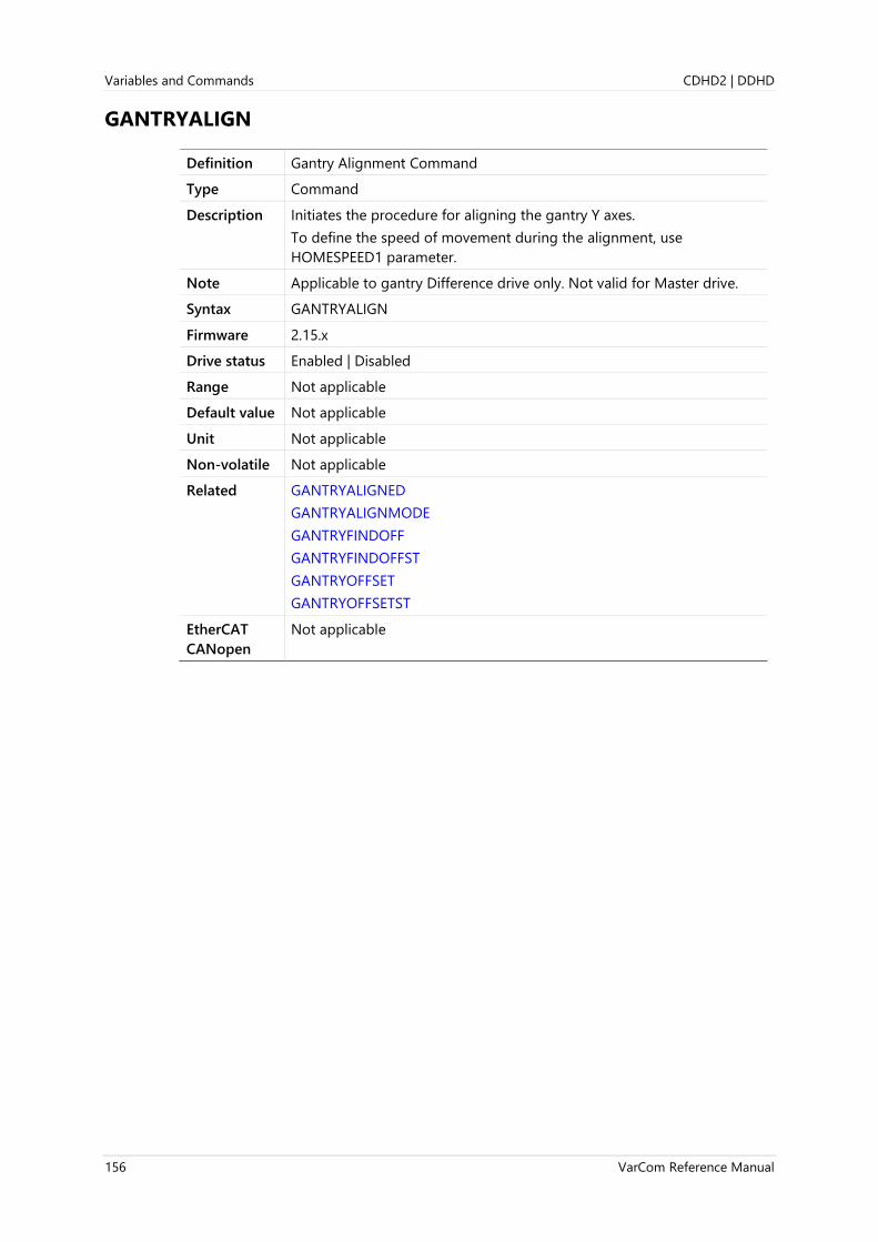
Variables and Commands CDHD2 | DDHD
156 VarCom Reference Manual
GANTRYALIGN
Definition Gantry Alignment Command
Type Command
Description Initiates the procedure for aligning the gantry Y axes.
To define the speed of movement during the alignment, use
HOMESPEED1 parameter.
Note Applicable to gantry Difference drive only. Not valid for Master drive.
Syntax GANTRYALIGN
Firmware 2.15.x
Drive status Enabled | Disabled
Range Not applicable
Default value Not applicable
Unit Not applicable
Non-volatile Not applicable
Related GANTRYALIGNED
GANTRYALIGNMODE
GANTRYFINDOFF
GANTRYFINDOFFST
GANTRYOFFSET
GANTRYOFFSETST
EtherCAT
CANopen
Not applicable

CDHD2 | DDHD Variables and Commands
VarCom Reference Manual 157
GANTRYALIGNED
Definition Gantry Alignment Status
Type Variable (R)
Description Indicates whether the gantry Y axes are aligned.
Syntax GANTRYALIGNED
Firmware 2.15.x
Drive status Enabled | Disabled
Range 0 = Gantry Y axes are not aligned
1 = Gantry Y axes are aligned
Default value Not applicable
Unit Not applicable
Non-volatile No
Related GANTRYALIGN
GANTRYALIGNMODE
GANTRYFINDOFF
GANTRYFINDOFFST
GANTRYOFFSET
GANTRYOFFSETST
EtherCAT
CANopen
2204h, sub-index 1

Variables and Commands CDHD2 | DDHD
158 VarCom Reference Manual
GANTRYALIGNMODE
Definition Gantry Alignment Mode
Type Variable (R/W)
Description Defines the alignment method for a gantry system.
Note Applicable to gantry Difference drive only. Not valid for Master drive.
Syntax Read: GANTRYALIGNMODE
Write: GANTRYALIGNMODE <value>
Firmware 2.15.x
Drive status Disabled
Range 0 = Gantry always considered aligned (gantry system=rigid)
1 = Align according to GANTRYOFFSET after both axes are homed (or
using multi-turn absolute encoders)
2 = Automatic alignment upon enable
Default value 1
Unit Not applicable
Non-volatile Yes
Related GANTRYALIGN
GANTRYALIGNED
GANTRYFINDOFF
GANTRYFINDOFFST
GANTRYOFFSET
GANTRYOFFSETST
EtherCAT
CANopen
2200h, sub-index 4

CDHD2 | DDHD Variables and Commands
VarCom Reference Manual 159
GANTRYCMDTYPE
Definition Gantry Command Type
Type Variable (R/W)
Description Defines how a gantry drive responds to reference commands, and
defines which position feedback value the drive will report through
EtherCAT/CANopen objects and encoder simulation.
When operating in OPMODE 4 (gearing mode), this parameter setting is
ignored, and GANTRYCMDTYPE 1 behavior is automatically enforced.
GANTRYCMDTYPE Master
Controller
Difference
Controller
1 Reference Command Y-axis ignored
1 Feedback Reporting (Y1 + Y2) ÷ 2 Y1 – Y2
2 Reference Command Y-axis Yaw axis
2 Feedback Reporting (Y1 + Y2) ÷ 2 Y1 – Y2
Note Master and Difference controller must have same GANTRYCMDTYPE
value.
Syntax Read: GANTRYCMDTYPE
Write: GANTRYCMDTYPE <value>
Firmware 2.15.x
Drive status Disabled
Range 1 = Reference command will be accepted by the gantry Master
controller, and rejected by the gantry Difference controller. The
position reported is the actual position of the motor (MFB)
connected to the drive.
2 = Reference command will be accepted by both Master controller
and Difference controller. Each drive responds to the command
according to its role in the gantry system, and reports the position
(PFB) accordingly.
Default value Not applicable
Unit Not applicable
Non-volatile Yes
Related GANTRYMODE
EtherCAT
CANopen
2200h, sub-index 2
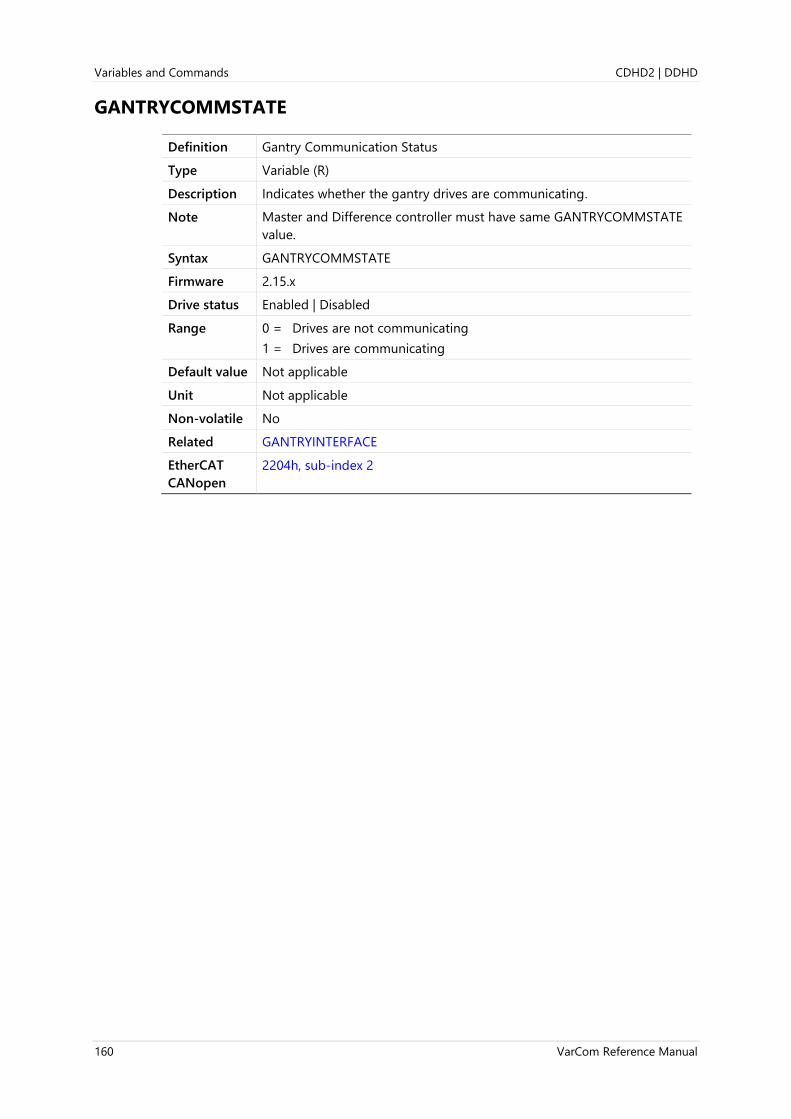
Variables and Commands CDHD2 | DDHD
160 VarCom Reference Manual
GANTRYCOMMSTATE
Definition Gantry Communication Status
Type Variable (R)
Description Indicates whether the gantry drives are communicating.
Note Master and Difference controller must have same GANTRYCOMMSTATE
value.
Syntax GANTRYCOMMSTATE
Firmware 2.15.x
Drive status Enabled | Disabled
Range 0 = Drives are not communicating
1 = Drives are communicating
Default value Not applicable
Unit Not applicable
Non-volatile No
Related GANTRYINTERFACE
EtherCAT
CANopen
2204h, sub-index 2

CDHD2 | DDHD Variables and Commands
VarCom Reference Manual 161
GANTRYDIFFICMD
Definition Current Command from Gantry Difference Controller
Type Variable (R)
Description Indicates the current command generated by the gantry difference
controller.
Syntax GANTRYDIFFICMD
Firmware 2.15.x
Drive status Enabled | Disabled
Range Not applicable
Default value Not applicable
Unit A
Non-volatile No
Related GANTRYDIFFPFB
GANTRYDIFFVFB
EtherCAT
CANopen
2203h, sub-index 2

Variables and Commands CDHD2 | DDHD
162 VarCom Reference Manual
GANTRYDIFFPFB
Definition Gantry Difference Position
Type Variable (R)
Description Indicates the gantry Difference position feedback value = (Y1-Y2)
Syntax GANTRYDIFFPFB
Firmware 2.15.x
Drive status Enabled | Disabled
Range If MOTORTYPE 0 (Rotary): ±(231 -1) [rev]
If MOTORTYPE 2 (Linear): ±(231 -1) [pitch]
Default value Not applicable
Unit If MOTORTYPE 0 (Rotary):
UNITSROTPOS 0 = rev
UNITSROTPOS 1 = count
UNITSROTPOS 2 = deg
If MOTORTYPE 2 (Linear):
UNITSLINPOS 0 = pitch
UNITSLINPOS 1 = count
UNITSLINPOS 3 = mm
Non-volatile No
Related GANTRYDIFFICMD
GANTRYDIFFVFB
EtherCAT
CANopen
2201h, sub-index 2

CDHD2 | DDHD Variables and Commands
VarCom Reference Manual 163
GANTRYDIFFVFB
Definition Gantry Difference Velocity
Type Variable (R)
Description Indicates the gantry Difference velocity feedback value = [V(Y1)-V(Y2)]
Syntax GANTRYDIFFVFB
Firmware 2.15.x
Drive status Enabled | Disabled
Range If MOTORTYPE 0 (Rotary): ±(231 -1) [rev]
If MOTORTYPE 2 (Linear): ±(231 -1) [pitch]
Default value Not applicable
Unit If MOTORTYPE 0 (Rotary):
UNITSROTPOS 0 = rev
UNITSROTPOS 1 = count
UNITSROTPOS 2 = deg
If MOTORTYPE 2 (Linear):
UNITSLINPOS 0 = pitch
UNITSLINPOS 1 = count
UNITSLINPOS 3 = mm
Non-volatile No
Related GANTRYDIFFICMD
GANTRYDIFFPFB
EtherCAT
CANopen
2202h, sub-index 2

Variables and Commands CDHD2 | DDHD
164 VarCom Reference Manual
GANTRYFINDOFF
Definition Gantry Find Offset Command
Type Command
Description Initiates the procedure for finding the value of the difference (in
distance) between the Y1 and Y2 reference points.
Syntax GANTRYFINDOFF
Firmware 2.15.x
Drive status Enabled | Disabled
Range Not applicable
Default value Not applicable
Unit Not applicable
Non-volatile Not applicable
Related GANTRYFINDOFFST
GANTRYOFFSET
GANTRYOFFSETST
EtherCAT
CANopen
2202h, sub-index 3

CDHD2 | DDHD Variables and Commands
VarCom Reference Manual 165
GANTRYFINDOFFST
Definition Gantry Find Offset Procedure Status
Type Variable (R)
Description Indicates the status of the gantry find offset procedure.
Syntax GANTRYFINDOFFST
Firmware 2.15.x
Drive status Enabled | Disabled
Range Not applicable
Default value Not applicable
Unit Not applicable
Non-volatile No
Related GANTRYFINDOFF
GANTRYOFFSET
GANTRYOFFSETST
EtherCAT
CANopen
Not applicable
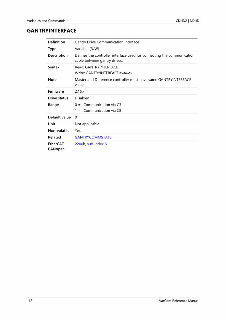
Variables and Commands CDHD2 | DDHD
166 VarCom Reference Manual
GANTRYINTERFACE
Definition Gantry Drive Communication Interface
Type Variable (R/W)
Description Defines the controller interface used for connecting the communication
cable between gantry drives.
Syntax Read: GANTRYINTERFACE
Write: GANTRYINTERFACE<value>
Note Master and Difference controller must have same GANTRYINTERFACE
value.
Firmware 2.15.x
Drive status Disabled
Range 0 = Communication via C3
1 = Communication via C8
Default value 0
Unit Not applicable
Non-volatile Yes
Related GANTRYCOMMSTATE
EtherCAT
CANopen
2200h, sub-index 6

CDHD2 | DDHD Variables and Commands
VarCom Reference Manual 167
GANTRYMODE
Definition Gantry Mode
Type Variable (R/W)
Description Gets/sets the gantry mode.
Defines whether the position loop is applied to the average value or the
difference in value of the two gantry motor positions.
When gantry Master is set, the position loop is applied to the average
position of the two gantry motors.
When gantry Difference is set, the position loop is applied to the
position difference between the two gantry motors.
Note GANTRYMODE 1 or 2 requires POSCONTROLMODE=5
When COMMODE=0 (serial communication; without fieldbus),
operation modes can be either Gearing mode (OPMODE 4) or Serial
Positioning mode (OPMODE 8)
When COMMODE=1 (EtherCAT/CANopen communication; with
fieldbus), operation modes can be Profile Position (mode 1), Cyclic
Synchronous Position (mode 8), Homing (mode 6).
Syntax Read: GANTRYMODE
Write: GANTRYMODE <value>
Firmware 2.15.x
Drive status Disabled
Range 0 = Gantry mode not active
1 = Gantry mode active, Master function
2 = Gantry mode active, Difference function
Default value 0
Unit Not applicable
Non-volatile Yes
Related GANTRYTYPE
EtherCAT
CANopen
2200h, sub-index 1
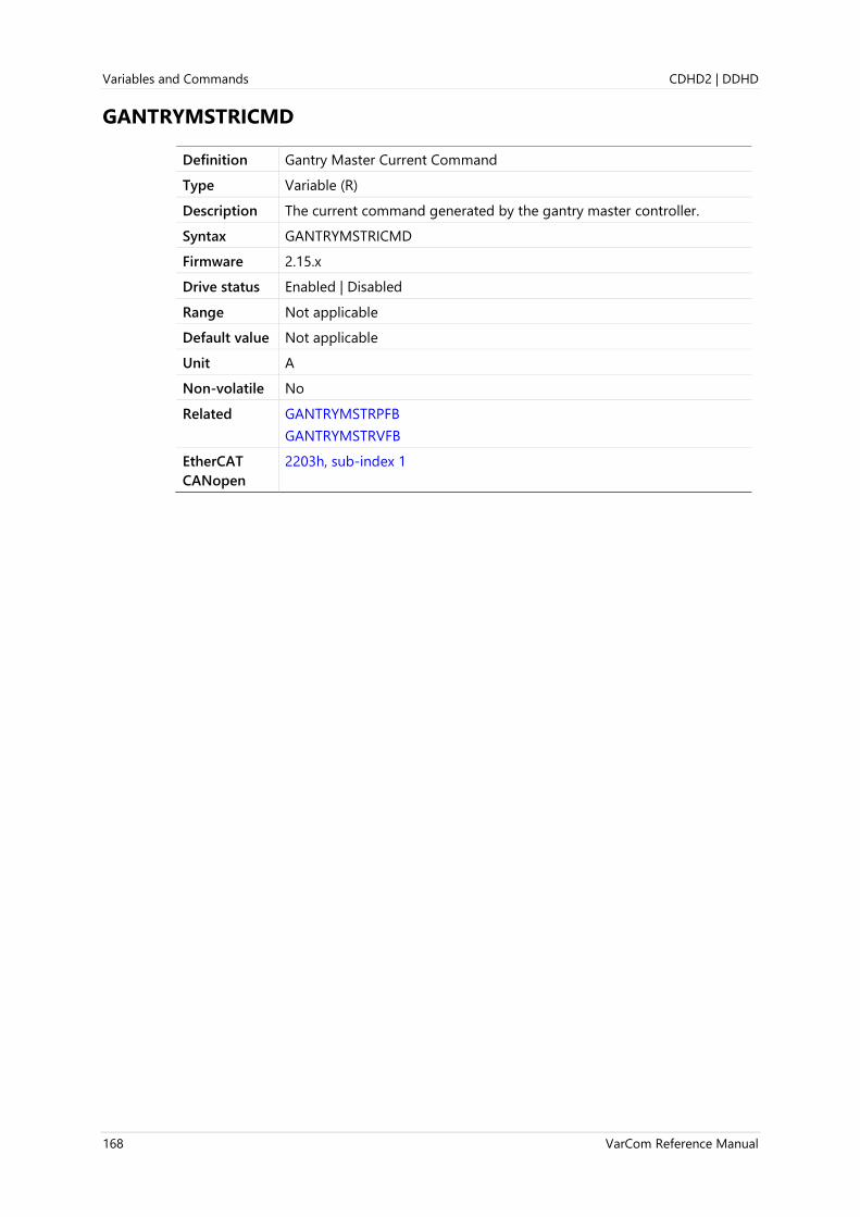
Variables and Commands CDHD2 | DDHD
168 VarCom Reference Manual
GANTRYMSTRICMD
Definition Gantry Master Current Command
Type Variable (R)
Description The current command generated by the gantry master controller.
Syntax GANTRYMSTRICMD
Firmware 2.15.x
Drive status Enabled | Disabled
Range Not applicable
Default value Not applicable
Unit A
Non-volatile No
Related GANTRYMSTRPFB
GANTRYMSTRVFB
EtherCAT
CANopen
2203h, sub-index 1
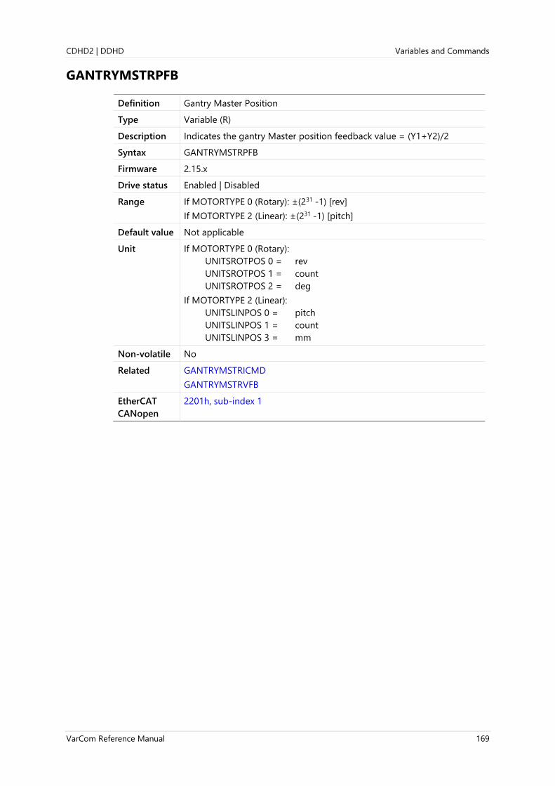
CDHD2 | DDHD Variables and Commands
VarCom Reference Manual 169
GANTRYMSTRPFB
Definition Gantry Master Position
Type Variable (R)
Description Indicates the gantry Master position feedback value = (Y1+Y2)/2
Syntax GANTRYMSTRPFB
Firmware 2.15.x
Drive status Enabled | Disabled
Range If MOTORTYPE 0 (Rotary): ±(231 -1) [rev]
If MOTORTYPE 2 (Linear): ±(231 -1) [pitch]
Default value Not applicable
Unit If MOTORTYPE 0 (Rotary):
UNITSROTPOS 0 = rev
UNITSROTPOS 1 = count
UNITSROTPOS 2 = deg
If MOTORTYPE 2 (Linear):
UNITSLINPOS 0 = pitch
UNITSLINPOS 1 = count
UNITSLINPOS 3 = mm
Non-volatile No
Related GANTRYMSTRICMD
GANTRYMSTRVFB
EtherCAT
CANopen
2201h, sub-index 1

Variables and Commands CDHD2 | DDHD
170 VarCom Reference Manual
GANTRYMSTRVFB
Definition Gantry Master Velocity
Type Variable (R)
Description Indicates the gantry Master gantry velocity feedback value = (V1+V2)/2
Syntax GANTRYMSTRVFB
Firmware 2.15.x
Drive status Enabled | Disabled
Range If MOTORTYPE 0 (Rotary): ±(231 -1) [rev]
If MOTORTYPE 2 (Linear): ±(231 -1) [pitch]
Default value Not applicable
Unit If MOTORTYPE 0 (Rotary):
UNITSROTPOS 0 = rev
UNITSROTPOS 1 = count
UNITSROTPOS 2 = deg
If MOTORTYPE 2 (Linear):
UNITSLINPOS 0 = pitch
UNITSLINPOS 1 = count
UNITSLINPOS 3 = mm
Non-volatile No
Related GANTRYMSTRICMD
GANTRYMSTRPFB
EtherCAT
CANopen
2202h, sub-index 1
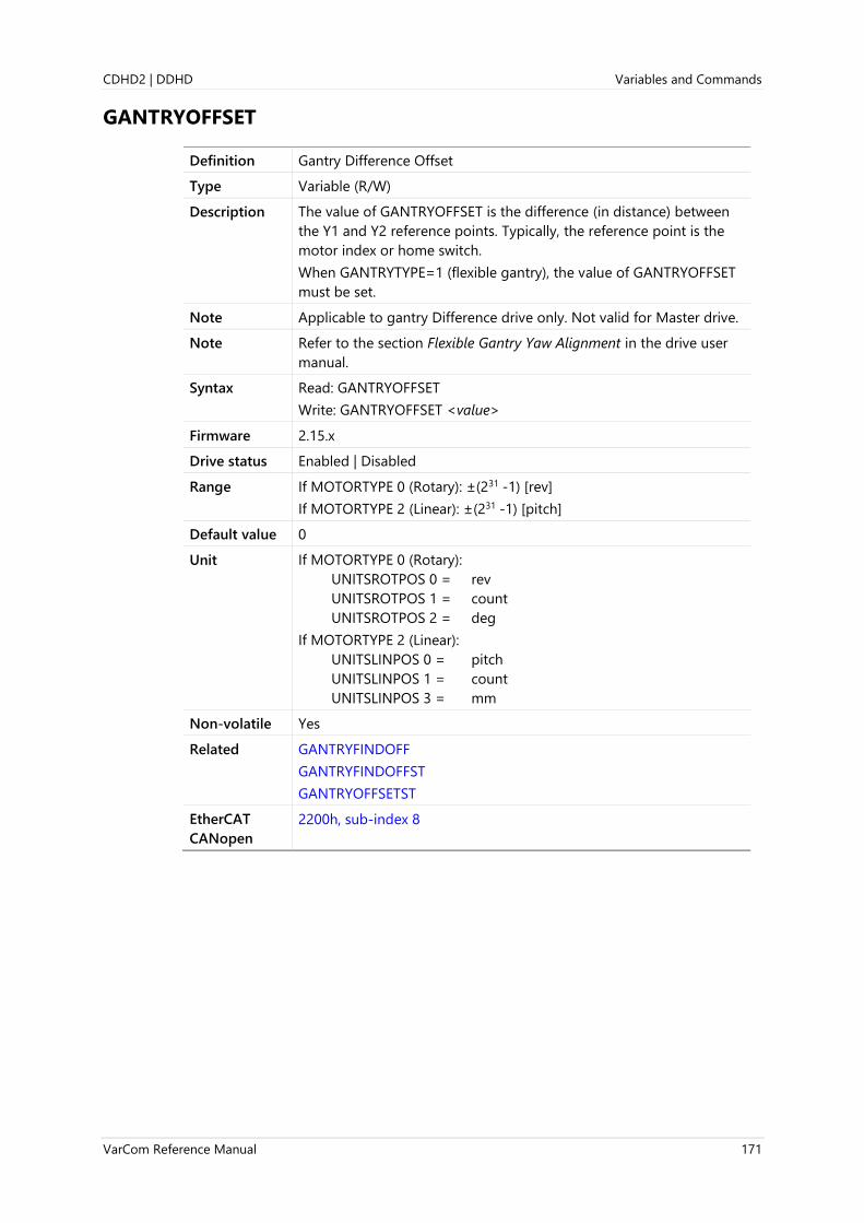
CDHD2 | DDHD Variables and Commands
VarCom Reference Manual 171
GANTRYOFFSET
Definition Gantry Difference Offset
Type Variable (R/W)
Description The value of GANTRYOFFSET is the difference (in distance) between
the Y1 and Y2 reference points. Typically, the reference point is the
motor index or home switch.
When GANTRYTYPE=1 (flexible gantry), the value of GANTRYOFFSET
must be set.
Note Applicable to gantry Difference drive only. Not valid for Master drive.
Note Refer to the section Flexible Gantry Yaw Alignment in the drive user
manual.
Syntax Read: GANTRYOFFSET
Write: GANTRYOFFSET <value>
Firmware 2.15.x
Drive status Enabled | Disabled
Range If MOTORTYPE 0 (Rotary): ±(231 -1) [rev]
If MOTORTYPE 2 (Linear): ±(231 -1) [pitch]
Default value 0
Unit If MOTORTYPE 0 (Rotary):
UNITSROTPOS 0 = rev
UNITSROTPOS 1 = count
UNITSROTPOS 2 = deg
If MOTORTYPE 2 (Linear):
UNITSLINPOS 0 = pitch
UNITSLINPOS 1 = count
UNITSLINPOS 3 = mm
Non-volatile Yes
Related GANTRYFINDOFF
GANTRYFINDOFFST
GANTRYOFFSETST
EtherCAT
CANopen
2200h, sub-index 8

Variables and Commands CDHD2 | DDHD
172 VarCom Reference Manual
GANTRYOFFSETST
Definition Gantry Difference Offset Validity
Type Variable (R/W)
Description If the value of GANTRYOFFSET is not valid, functions related to
gantry alignment will not apply the offset value.
Syntax Read: GANTRYOFFSETST
Write: GANTRYOFFSETST <value>
Firmware 2.15.x
Drive status Enabled | Disabled
Range 0 = offset value is not valid
1 = offset value is valid
Default value 0
Unit Not applicable
Non-volatile Yes
Related GANTRYFINDOFF
GANTRYFINDOFFST
GANTRYOFFSET
EtherCAT
CANopen
2202h, sub-index 7

CDHD2 | DDHD Variables and Commands
VarCom Reference Manual 173
GANTRYPRTNRICMD
Definition Partner Axis ICMD Value
Type Variable (R)
Description Indicates the ICMD value in the other (partner) gantry drive.
Syntax GANTRYPRTNRICMD
Firmware 2.15.x
Drive status Enabled | Disabled
Range Not applicable
Default value Not applicable
Unit A
Non-volatile No
Related GANTRYPRTNRMFB
GANTRYPRTNRVFB
EtherCAT
CANopen
Not applicable

Variables and Commands CDHD2 | DDHD
174 VarCom Reference Manual
GANTRYPRTNRMFB
Definition Gantry Partner Axis MFB Value
Type Variable (R)
Description Indicates the MFB value in the other (partner) gantry drive.
Syntax GANTRYPRTNRMFB
Firmware 2.15.x
Drive status Enabled | Disabled
Range If MOTORTYPE 0 (Rotary): ±(231 -1) [rev]
If MOTORTYPE 2 (Linear): ±(231 -1) [pitch]
Default value Not applicable
Unit If MOTORTYPE 0 (Rotary):
UNITSROTPOS 0 = rev
UNITSROTPOS 1 = count
UNITSROTPOS 2 = deg
If MOTORTYPE 2 (Linear):
UNITSLINPOS 0 = pitch
UNITSLINPOS 1 = count
UNITSLINPOS 3 = mm
Non-volatile No
Related MFB
GANTRYPRTNRICMD
GANTRYPRTNRVFB
EtherCAT
CANopen
Not applicable

CDHD2 | DDHD Variables and Commands
VarCom Reference Manual 175
GANTRYPRTNRVFB
Definition Gantry Partner Axis Velocity
Type Variable (R)
Description Indicates the velocity value in the other (partner) gantry drive.
Syntax GANTRYPRTNRVFB
Firmware 2.15.x
Drive status Enabled | Disabled
Range If MOTORTYPE 0 (Rotary): ±(231 -1) [rev]
If MOTORTYPE 2 (Linear): ±(231 -1) [pitch]
Default value Not applicable
Unit If MOTORTYPE 0 (Rotary):
UNITSROTPOS 0 = rev
UNITSROTPOS 1 = count
UNITSROTPOS 2 = deg
If MOTORTYPE 2 (Linear):
UNITSLINPOS 0 = pitch
UNITSLINPOS 1 = count
UNITSLINPOS 3 = mm
Non-volatile No
Related GANTRYPRTNRICMD
GANTRYPRTNRMFB
EtherCAT
CANopen
Not applicable

Variables and Commands CDHD2 | DDHD
176 VarCom Reference Manual
GANTRYTYPE
Definition Gantry Type
Type Variable (R/W)
Description Defines whether the gantry structure is rigid or flexible.
For rigid gantry system, GANTRYTYPE must be set to 0.
For flexible gantry system, GANTRYTYPE must be set to 1.
Note Master and Difference controller must have same GANTRYTYPE value.
Syntax Read: GANTRYTYPE
Write: GANTRYTYPE <value>
Firmware 2.15.x
Drive status Disabled
Range 0 = Rigid gantry system (axis alignment not applicable)
1 = Flexible gantry system (axis alignment required)
Default value 0
Unit Not applicable
Non-volatile Yes
Related GANTRYMODE
EtherCAT
CANopen
2200h, sub-index 5

CDHD2 | DDHD Variables and Commands
VarCom Reference Manual 177
GEAR
Definition Gearing
Type Variable (R/W)
Description Enables and disables the gearing/pulse-train function.
Syntax Read: GEAR
Write: GEAR <value>
Firmware 1.0.6
Drive status Enabled | Disabled
Range 0 = Gearing not active
1 = Gearing activated
Default value 1
Unit Not applicable
Non-volatile Yes
Related GEARMODE
EtherCAT
CANopen
211Eh, sub-index 0

Variables and Commands CDHD2 | DDHD
178 VarCom Reference Manual
GEARACCTHRESH
Definition Gearing Acceleration Threshold
Type Variable (R/W)
Description Maximum acceleration for gearing.
Used for the combination of HD position controller
(POSCONTROLMODE 2 or 1) and gearing input (OPMODE 4).
This threshold defines the value below which the acceleration derived
from the gear filter as input to the position controller is 0.
Syntax Read: GEARACCTHRESH
Write: GEARACCTHRESH <value>
Firmware 1.0.6
Drive status Enabled | Disabled
Range If MOTORTYPE 0 (Rotary):
UNITSROTACC 0 = 0 to 16666.666
UNITSROTACC 1 = 0 to 1000000
UNITSROTACC 2 = 0 to 6000000
If MOTORTYPE 2 (Linear):
UNITSLINACC 1 = 0 to 533333.333
Default value If MOTORTYPE 0 (Rotary):
UNITSROTACC 0 = 16666.667
UNITSROTACC 1 = 1000000.000
UNITSROTACC 2 = 6000000.000
If MOTORTYPE 2 (Linear):
UNITSLINACC 1 = 533333.333
Unit If MOTORTYPE 0 (Rotary):
UNITSROTACC 0 = rps/s
UNITSROTACC 1 = rpm/s
UNITSROTACC 2 = deg/s2
If MOTORTYPE 2 (Linear):
UNITSLINACC 1 = mm/s2
Non-volatile Yes
Related GEARMODE
OPMODE
POSCONTROLMODE
EtherCAT
CANopen
2120h, sub-index 0
Panel P 1 1 0 7

CDHD2 | DDHD Variables and Commands
VarCom Reference Manual 179
GEARDBVAL
Definition Gearing Deadband Value
Type Variable (R/W)
Description Gets/sets a deadband value for a master encoder input. Applicable only
when an encoder following mode (ENCFOLLOWER) is active.
Syntax Read: GEARDBVAL
Write: GEARDBVAL <value>
Firmware 1.40.0
Drive status Enabled | Disabled
Range 0 to 32767
Default value 2
Unit Not applicable
Non-volatile Yes
Related ENCFOLLOWER
EtherCAT
CANopen
Not applicable

Variables and Commands CDHD2 | DDHD
180 VarCom Reference Manual
GEARFILTAFF
Definition Gearing Filter Acceleration Feedforward
Type Variable (R/W)
Description Gets/sets the value of the gear filter acceleration feedforward.
Syntax Read: GEARFILTAFF
Write: GEARFILTAFF <value>
Firmware 1.0.6
Drive status Disabled
Range ±2
Default value 0.000
Unit Not applicable
Non-volatile Yes
Related GEARMODE
EtherCAT
CANopen
2121h, sub-index 0
Panel P 1 1 0 9

CDHD2 | DDHD Variables and Commands
VarCom Reference Manual 181
GEARFILTDEPTH
Definition Gearing Filter Depth
Type Variable (R/W)
Description Applicable when GEARFILTMODE=1.
Gear filter depth, in 0.25 ms quanta.
Increasing GEARFILTDEPTH smooths the input command PTPVCMD, but
adds a delay.
GEARFILTDEPTH = ~2 x input step width
Syntax Read: GEARFILTDEPTH
Write: GEARFILTDEPTH<value>
Firmware 2.0.x
Drive status Disabled
Range 0.75 to 32
Default value 2.000
Unit ms
Non-volatile Yes
Related
EtherCAT
CANopen
220Ah, sub-index 0

Variables and Commands CDHD2 | DDHD
182 VarCom Reference Manual
GEARFILTMODE
Definition Gearing Filter Mode
Type Variable (R/W)
Description Defines whether or not gearing filter is activated.
Syntax Read: GEARFILTMODE
Write: GEARFILTMODE <value>
Firmware 1.0.6
Drive status Disabled
Range 0 = Gearing filter not activated.
1 = Gearing filter activated. For firmware version 2.0.x and higher
2 = Gearing filter activated. For firmware versions prior to 2.0.x.
Maintained for backward compatibility.
Default value 0
Unit Not applicable
Non-volatile Yes
Related GEARFILTT1
GEARFILTT2
GEARMODE
EtherCAT
CANopen
2122h, sub-index 0
Panel P 1 1 0 4

CDHD2 | DDHD Variables and Commands
VarCom Reference Manual 183
GEARFILTT1
Definition Gearing Filter Depth
Note Maintained for backward compatibility with firmware versions prior
to 2.0.x.
Type Variable (R/W)
Description Applicable when GEARFILTMODE=2.
Gearing filter depth, in 0.25 ms quanta.
Increasing GEARFILTT1 smooths the input command PTPVCMD, but
adds a delay.
GEARFILTT1 = ~2 x input step width
Syntax Read: GEARFILTT1
Write: GEARFILTT1 <value>
Firmware 1.0.6
Drive status Disabled
Range 0.75 to 32
Default value 2.000
Unit ms
Non-volatile Yes
Related GEARFILTT2
GEARMODE
EtherCAT
CANopen
2123h, sub-index 0
Panel P 1 1 0 5

Variables and Commands CDHD2 | DDHD
184 VarCom Reference Manual
GEARFILTT2
Definition Gearing Filter Velocity and Acceleration Depth
Type Variable (R/W)
Description Gearing filter velocity and acceleration depth.
Increasing GEARFILTT2 and VELFF compensates for the delay, but adds
overshoots.
If VELFF= GEARFILTT2: no delay
Syntax Read: GEARFILTT2
Write: GEARFILTT2 <value>
Firmware 1.0.6
Drive status Disabled
Range 0 to 60
Default value 4.000
Unit ms
Non-volatile Yes
Related GEARFILTT1
GEARMODE
EtherCAT
CANopen
2124h, sub-index 0
Panel P 1 1 0 6

CDHD2 | DDHD Variables and Commands
VarCom Reference Manual 185
GEARFILTVELFF
Definition Gearing Filter Velocity Feedforward
Type Variable (R/W)
Description Gets/sets the Gearing filter velocity feedforward.
Note Was GEARFILTVFF in earlier firmware versions.
Syntax Read: GEARFILTVELFF
Write: GEARFILTVELFF <value>
Firmware 1.3.2
Drive status Disabled
Range ±200
Default value 0.000
Unit ms
Non-volatile Yes
Related GEARFILTAFF
GEARFILTMODE
GEARFILTT1
GEARFILTT2
GEARMODE
EtherCAT
CANopen
2125h, sub-index 0
Panel P 1 1 0 8

Variables and Commands CDHD2 | DDHD
186 VarCom Reference Manual
GEARIN
Definition Gearing Ratio Numerator
Type Variable (R/W)
Description Gets/sets the numerator of the gearing equation.
The gearing relationship is as follows:
𝐺𝐸𝐴𝑅𝐼𝑁
𝐺𝐸𝐴𝑅𝑂𝑈𝑇 ×
1
𝑋𝐸𝑁𝐶𝑅𝐸𝑆
Gearing sets up a relationship between the number of input pulses
(HWPEXT counts) and the position increments of the motor shaft (or
actual motor position, PFB).
The rate at which position increments of the motor shaft (motor speed)
occur is determined by the gearing relationship and the line frequency
of the pulse train.
The direction of rotation is determined by the sign of the variable
GEARIN.
Note The HWPEXT/PCMD ratio is not maintained under the following
condition:
GEAROUT=1
GEARIN>5000
No warning is issued.
Syntax Read: GEARIN
Write: GEARIN <value>
Firmware 1.0.6
Drive status Enabled | Disabled
Range ±2147483647
Default value 1
Unit Not applicable
Non-volatile Yes
Related GEARMODE
GEAROUT
EtherCAT
CANopen
2126h, sub-index 0
Panel P 0 0 0 5

CDHD2 | DDHD Variables and Commands
VarCom Reference Manual 187
GEARINMODE
Definition Gearing Input Interpolation
Type Variable (R/W)
Description Used for gearing that is fed through the Controller I/F connector only.
Enables interpolation of the gearing signal and increase of resolution by
a factor of 16.
Syntax Read: GEARINMODE
Write: GEARINMODE <value>
Firmware 1.0.6
Drive status Disabled
Range 0 = Gearing input interpolation not activated
1 = Gearing input interpolation activated
Default value 1
Unit Not applicable
Non-volatile Yes
Related GEARMODE
HWPEXT
EtherCAT
CANopen
2127h, sub-index 0

Variables and Commands CDHD2 | DDHD
188 VarCom Reference Manual
GEARLIMITSMODE
Definition Gearing Operation Mode Behavior
Type Variable (R/W)
Description Defines how the drive performs electronic gearing when operating in
Gearing/Pulse Train mode (OPMODE 4).
This is a bit-wise parameter, hence the range 0 to 31.
The bits have the following meanings.
Bit 0:
0= If the drive is disabled or if HOLD 0 is in effect, incoming master
pulses are discarded.
1 = Even if the drive is disabled, incoming master pulses are evaluated.
Bit 1:
0 = If a limit switch has been activated, incoming master pulses that
command motion in the direction of the activated switch are
discarded.
1 = If a limit switch has been activated, and even if the motor has
stopped, incoming master pulses that command motion in the
direction of the activated switch are evaluated.
Bit 2:
0= Trajectory of the master is not limited by the ACC, DEC and VLIM
settings of the drive.
1 = Trajectory of the master is limited by the ACC, DEC and VLIM
settings of the drive.
Bit 3:
0= Follows the master position with compensation for the position lag
between the master and the slave, which may be caused by the
ACC, DEC or VLIM settings.
1 = Does not compensate for the position lag between the master and
the slave.
Bit 4:
0= Does not allow overshoot of the master position. The trajectory
generator of the slave always attempts to decelerate into the
target position of the master.
1 = Allows the slave to run synchronously with the master, which may
result in the slave overshooting the target position of the master
(particularly if acceleration and deceleration limits cause an abrupt
stop of the master).
Note If bit 0 is set, bit 2 must also be set. Since the position difference
between the master and the slave may increase while drive is in
disabled state, it is necessary to apply ACC, DEC, VLIM settings after the
drive is reenabled.
Note If bits 2 and 3 are set at the same time, bit 4 must also be set.
Note If bits 2 and 4 (but not 3) are set at the same time, overshoot may occur
if VLIM is significantly higher than actual motor speed.
Syntax Read: GEARLIMITSMODE
Write: GEARLIMITSMODE <value>

CDHD2 | DDHD Variables and Commands
VarCom Reference Manual 189
Firmware 1.0.6
Drive status Enabled | Disabled
Range 0 to 31
(If all bits are true, the bit-combination in binary format is 0011111,
which has a decimal value of 31.)
Default value 0
Unit Not applicable
Non-volatile Yes
Examples GEARLIMITSMODE 28 (binary: 00011100 = bits 2, 3 and 4 are set)
GEARLIMITSMODE 20 (binary: 00010100 = bits 2 and 4 are set)
GEARLIMITSMODE 5 (binary: 00000101 = bits 0 and 2 are set)
Related GEARFILTMODE
GEARMODE
EtherCAT
CANopen
2128h, sub-index 0
Panel P 5 0 0 2

Variables and Commands CDHD2 | DDHD
190 VarCom Reference Manual
GEARMODE
Definition Gearing/Pulse Train Operation Mode
Type Variable (R/W)
Description Gets/sets the gearing source and method.
Syntax Read: GEARMODE
Write: GEARMODE <value>
Firmware 1.0.6
Drive status Disabled
Range 0 = Encoder following.
Signals are received on the Controller interface (C2) at pins 28 and
11 (Quadrature A), and pins 9 and 27 (Quadrature B).
1 = Pulse and direction.
Signals are received on the Controller interface (C2) at pins 28 and
11 (Pulse), and 9 and 27 (Direction).
2 = CW/CCW (Up/Down) counting (controller interface).
Signals are received on the Controller interface (C2) at pins 28 and
11 (Up) and pins 9 and 27 (Down).
3 = Encoder following – secondary encoder.
Signals are received on the Machine interface (C3) at pins 1 and 11
(Quadrature A) and pins 2 an 12 (Quadrature B).
4 = Pulse and direction – secondary encoder.
Signals are received on the Machine interface (C3) at pins 1 and 11
(Pulse), and 2 and 12 (Direction).
Note GEARMODE 0, 1, 2:
If inputs 5 and 6 are set, respectively, to INMODE 17 and 18, signals are
received instead from fast inputs 5 and 6 on the Controller interface
(C2) at pins 32 and 15.
Default value 1
Unit Not applicable
Non-volatile Yes
Related GEARIN
GEAROUT
INMODE
OPMODE
PCMD
EtherCAT
CANopen
20B3h, sub-index 0
Panel P 0 0 0 2

CDHD2 | DDHD Variables and Commands
VarCom Reference Manual 191
GEAROUT
Definition Gearing Ratio Denominator
Type Variable (R/W)
Description Gets/sets the denominator of the gearing equation.
The gearing relationship is as follows:
𝐺𝐸𝐴𝑅𝐼𝑁
𝐺𝐸𝐴𝑅𝑂𝑈𝑇 ×
1
𝑋𝐸𝑁𝐶𝑅𝐸𝑆
Gearing sets up a relationship between the number of input pulses
(HWPEXT counts) and the position increments of the motor shaft (or
actual motor position, PFB).
The rate at which position increments of the motor shaft (motor speed)
occur is determined by the gearing relationship and the line frequency
of the pulse train.
Note The HWPEXT/PCMD ratio is not maintained under the following
condition:
GEAROUT=1
GEARIN>5000
No warning is issued.
Syntax Read: GEAROUT
Write: GEAROUT <value>
Firmware 1.0.6
Drive status Enabled | Disabled
Range ±2147483647
Default value 1
Unit Not applicable
Non-volatile Yes
Related GEARIN
GEARMODE
EtherCAT
CANopen
2129h, sub-index 0
Panel P 0 0 0 6

Variables and Commands CDHD2 | DDHD
192 VarCom Reference Manual
GET
Definition Get Recorded Data
Type Command
Description Gets the recorded data that was captured using the recording
mechanism. The data is retrieved in ASCII or binary format according to
the value of GETMODE.
Syntax GET
Firmware 1.0.6
Drive status Enabled | Disabled
Range Not applicable
Default value Not applicable
Unit Not applicable
Non-volatile Not applicable
Related GETMODE
RECORD
Example -->get
Binary Units Frame:
HD Recording (Binary Format(
1000,32
"PE","VCMD","V"
0.000,0.000,0.000
0.000,0.000,0.000
0.000,0.000,0.000
0.000,20.176,0.000
0.000,74.176,0.000
0.000,128.176,0.000
0.000,182.176,14.736
0.000,236.176,31.747
...
0.000,1999.978,1999.471
0.000,1999.978,1998.976
0.000,1999.978,1998.779
0.000,1999.978,2000.559
0.000,1999.978,1999.471
0.000,1999.978,1998.383
0.000,1999.978,1998.581
0.000,1999.978,2001.943
...
0.000,0.000,0.000
0.000,0.000,0.000
-->
CANopen 20E7, sub-index 1

CDHD2 | DDHD Variables and Commands
VarCom Reference Manual 193
GETMODE
Definition Recorded Data Transfer Format
Type Variable (R/W)
Description Gets/sets the data transfer format used by the GET command.
Syntax Read: GETMODE
Write: GETMODE <value>
Firmware 1.0.6
Drive status Enabled | Disabled
Range 0 = ASCII data transfer format
3 = Binary data transfer format
4 = Binary data transfer format, including header data
8 = ASCII data transfer format, including drive parameters
11 = Binary data transfer format, including drive parameters
Default value 3
Unit Not applicable
Non-volatile Yes
Related GET
RECORD
EtherCAT
CANopen
Not applicable

Variables and Commands CDHD2 | DDHD
194 VarCom Reference Manual
GETREC
Definition Get Line of Recorded Data
Type Command
Description Gets a specific line from the last buffer of recorded data that was
captured using RECORD. For example, GETREC 5 returns the fifth line of
the last recorded buffer.
To retrieve data using this command, GETMODE3.
Syntax GETREC {value}
Firmware 1.3.2
Drive status Enabled | Disabled
Range Not applicable
Default value Not applicable
Unit Not applicable
Non-volatile Not applicable
Related RECORD
EtherCAT
CANopen
Not applicable

CDHD2 | DDHD Variables and Commands
VarCom Reference Manual 195
HALLS
Definition Hall Signals
Type Variable (R)
Description Indicates the current state of the Hall commutation sensors.
Syntax HALLS
Firmware 1.0.6
Drive status Enabled | Disabled
Range 0 = Hall sensor in low position
1 = Hall sensor in high position
Default value Not applicable
Unit Not applicable
Non-volatile No
Example -->halls
Hu Hv Hw
1 1 1
-->
Related ELECTANGLE
FEEDBACKTYPE
MECHANGLE
MENCTYPE
EtherCAT
CANopen
2056h, sub-index 1

Variables and Commands CDHD2 | DDHD
196 VarCom Reference Manual
HALLSCOMMTHRESH
Definition Halls-Only Commutation Source Threshold
Type Variable (R/W)
Description Gets/sets the threshold value for Halls-only (MENCTYPE 5)
commutation, in Hall signals per seconds.
When the Hall sensor signaling rate goes above the threshold,
commutation changes to sine commutation.
When the Hall sensor signaling rate falls below 75% of threshold value,
commutation changes to six-step commutation.
Syntax Read: HALLSCOMMTHRESH
Write: HALLSCOMMTHRESH <value>
Firmware 1.40.0
Drive status Enabled | Disabled
Range 10 to 10,000
Default value 40
Unit Hall signals per second
Non-volatile Yes
Related HALLSONLYCOMM
MENCTYPE 5
EtherCAT
CANopen
Not applicable
Panel P 2 0 1 5

CDHD2 | DDHD Variables and Commands
VarCom Reference Manual 197
HALLSFILTAFF
Definition Halls-Only Mean Square Filter Acceleration Feedforward
Type Variable (R/W)
Description Provides adjustable gain for the acceleration feedforward from the
mean square filter for Halls-only feedback.
Syntax Read: HALLSFILTAFF
Write: HALLSFILTAFF <value>
Firmware 1.4.4
Drive status Disabled
Range -2 to 2
Default value 0.000
Unit Not applicable
Non-volatile Yes
Related FEEDBACKTYPE
HALLS
HALLSFILTT1
HALLSFILTT2
MENCTYPE
EtherCAT
CANopen
Not applicable
Panel P 2 0 1 7

Variables and Commands CDHD2 | DDHD
198 VarCom Reference Manual
HALLSFILTT1
Definition Halls-Only Mean Square Filter Depth
Type Variable (R/W)
Description Filtering time constant for Halls-only position feedback, in 125 µs
quanta.
Syntax Read: HALLSFILTT1
Write: HALLSFILTT1 <value>
Firmware 1.4.4
Drive status Disabled
Range 0.375 to 32
Default value 2.000
Unit ms
Non-volatile Yes
Related HALLSFILTAFF
HALLSFILTT2
HALLSFILTVELFF
MENCTYPE
EtherCAT
CANopen
Not applicable
Panel P 2 0 1 8

CDHD2 | DDHD Variables and Commands
VarCom Reference Manual 199
HALLSFILTT2
Definition Halls-Only Mean Square Filter Velocity and Acceleration Filter Depth
Type Variable (R/W)
Description Filtering time constant for Halls-only velocity and acceleration
indications, in 125 µs quanta.
Syntax Read: HALLSFILTT2
Write: HALLSFILTT2<value>
Firmware 1.4.4
Drive status Disabled
Range 0 to 32
Default value 4.000
Unit ms
Non-volatile Yes
Related HALLSFILTAFF
HALLSFILTT1
HALLSFILTVELFF
MENCTYPE
EtherCAT
CANopen
Not applicable
Panel P 2 0 1 9

Variables and Commands CDHD2 | DDHD
200 VarCom Reference Manual
HALLSFILTVELFF
Definition Halls-Only Mean Square Filter Velocity Feedforward
Type Variable (R/W)
Description Halls-only filter velocity feedforward output gain.
Syntax Read: HALLSFILTVELFF
Write: HALLSFILTVELFF <value>
Firmware 1.4.4
Drive status Disabled
Range -32 to 32
Default value 0.000
Unit ms
Non-volatile Yes
Related HALLSFILTAFF
HALLSFILTT1
HALLSFILTT2
MENCTYPE
EtherCAT
CANopen
Not applicable
Panel P 2 0 2 0

CDHD2 | DDHD Variables and Commands
VarCom Reference Manual 201
HALLSINV
Definition Hall Signals Inversion
Type Variable (R/W)
Description Inverts the polarity of individual Hall signals associated with motor
phases UVW, thereby providing correction for crossed wiring. This
variable is set during the MOTORSETUP procedure.
Syntax Read: HALLSINV
Write: HALLSINV {0|1} {0|1} {0|1}
Firmware 1.0.6
Drive status Enabled | Disabled
Range 0 = Hall signal not inverted
1 = Hall signal inverted
Default value 0
Unit Not applicable
Non-volatile Yes
Example -->hallsinv 1 1 0
-->halls
Hu Hv Hw
0 0 1
-->hallsinv 1 0 0
-->halls
Hu Hv Hw
0 1 1
-->
Related FEEDBACKTYPE
HALLS
HALLSTYPE
MOTORSETUP
MENCTYPE
EtherCAT
CANopen
2057h, sub-index 1
Panel P 2 0 0 9

Variables and Commands CDHD2 | DDHD
202 VarCom Reference Manual
HALLSONLYCOMM
Definition Halls-Only Commutation Mode
Type Variable (R/W)
Description Defines whether the Halls-only commutation (MENCTYPE 5) is
performed according to six-step phase currents, or whether it is based
on an extrapolated position.
Syntax Read: HALLSONLYCOMM
Write: HALLSONLYCOMM <value>
Firmware 1.40.0
Drive status Enabled | Disabled
Range 0 = Six-step commutation with MPHASE correction (backward
compatible)
1 = Commutation is based on an extrapolated position while velocity
exceeds the threshold of Hall signals per second set by
HALLSCOMMTHRESH, and changes to six-step when velocity falls
below 75% of the Hall signals per second threshold.
Default value 0
Unit Not applicable
Non-volatile Yes
Related HALLSCOMMTHRESH
MENCTYPE 5
EtherCAT
CANopen
2179h, sub-index 0
Panel P 2 0 1 6

CDHD2 | DDHD Variables and Commands
VarCom Reference Manual 203
HALLSTYPE
Definition Hall Signals Type
Type Variable (R/W)
Description Gets/sets the source and method used for Hall sensors.
Syntax Read: HALLSTYPE
Write: HALLSTYPE <value>
Firmware 1.0.6
Drive status Enabled | Disabled
CDHD2 Range 0 = Single-ended connection through the Feedback connector (C4)
1 = Differential connection through the Feedback connector (C4)
2 = Differential connection through the Machine I/F connector (C3)
Refer to pinout information in the product user manual.
DDHD Range 0 = Single-ended connection through Feedback connector (C2 or C3), at pins 4, 5 and 17
3 = Differential connection through Feedback connector (C2 or C3), at pins 6, 19, 7, 20, 9 and 22.
Refer to pinout information in the product user manual.
Default value 0
Unit Not applicable
Non-volatile Yes
Related FEEDBACKTYPE
HALLS
HALLSINV
MOTORSETUP
MENCTYPE
EtherCAT
CANopen
2058h, sub-index 0
Panel P 2 0 1 0

Variables and Commands CDHD2 | DDHD
204 VarCom Reference Manual
HOLD
Definition Hold Position Command
Type Command
Description Instructs motor whether to maintain its position.
Syntax HOLD Queries the Hold state
HOLD {0|1} Defines the Hold state
Firmware 1.0.6
Drive status Enabled | Disabled
Range 0 = Do not hold position
1 = Hold position
Default value 0
Unit Not applicable
Non-volatile No
Related J
OPMODE
MOVEINC
STOPPED
EtherCAT
CANopen
2063h, sub-index 0
Panel P 7 1 0 6

CDHD2 | DDHD Variables and Commands
VarCom Reference Manual 205
HOLDMODE
Definition Resume Motion or Homing After Hold Interrupt
Type Variable (R/W)
Description Defines whether or not an interrupted motion or homing will resume
once the input that triggered the hold is released.
Hold in OPMODE 0 (Velocity control) or
Hold in OPMODE 8 (Position control):
When the digital input configured for the Hold function
(INMODE <i#> 30) is activated, the drive stops (according to DECSTOP)
and command execution is paused.
While in the Hold state, a warning is indicated both on the drive’s digital
display (blinking operation mode) and in response to ST (“HOLD mode
active” message).
In addition, while in the Hold state, STOPPED= -1, indicating that
movement has been interrupted.
If HOLDMODE=1 (and OPMODE=0 or 8):
When the Hold input is released, the drive resumes the interrupted
motion, and continues to the original target (Position mode) or
executes a jog according to the original JOG command (Velocity
mode).
Once the original motion has resumed, STOPPED=0.
When the original command is completed, STOPPED=2, indicating
the motion profile has been completed.
If HOLDMODE=0 (and OPMODE=0 or 8):
When the Hold input is released, the drive does not resume the
interrupted motion. A new command can be generated by
applying a new MOVEINC or MOVEABS command.
Hold during Homing:
When the digital input configured for the Hold function (INMODE <i#>
30) is activated, the drive halts the homing process and the motor stops.
While in the Hold state, a warning is indicated both on the drive’s digital
display (blinking operation mode) and in response to ST (Hold Mode
Active message).
If HOLDMODE=1:
When the Hold input is released, the homing process automatically
restarts.
If HOLDMODE=0:
When the Hold input is released, the drive does not resume the
interrupted homing sequence (HOMESTATE=20, indicating homing
failed). A new homing command can be generated by issuing a
new HOMECMD command.
Syntax Read: HOLDMODE
Write: HOLDMODE <value>
Firmware 1.20.6
Drive status Enabled | Disabled
Variables and Commands CDHD2 | DDHD
206 VarCom Reference Manual
Range 0 = When the Hold input is released, the interrupted
movement/homing does not resume.
1 = When the Hold input is released, the interrupted
movement/homing resumes.
Default value 0
Unit Not applicable
Non-volatile Yes
Related INMODE 30
EtherCAT
CANopen
Not applicable

CDHD2 | DDHD Variables and Commands
VarCom Reference Manual 207
HOMEACC
Definition Homing Acceleration
Type Variable (R/W)
Description Acceleration (and deceleration) for the homing process.
HOMEACC is defined according to the units currently in effect. It is used
in acceleration and deceleration of all trajectories (moves) during
homing.
If and when a limit switch is engaged, emergency stop goes into effect
according to DECSTOP and/or DECSTOPTIME, and overrides HOMEACC.
Syntax Read: HOMEACC
Write: HOMEACC <value>
Firmware 1.2.12
Drive status Enabled | Disabled
Range If MOTORTYPE 0 (Rotary):
UNITSROTACC 0 = 0.004 to 16666.666
UNITSROTACC 1 = 0.224 to 1000000
UNITSROTACC 2 = 1.342 to 6000000
If MOTORTYPE 2 (Linear):
UNITSLINACC 1 = 0.12 to 533333.333
Default value 4000 [rpm/s]
Unit If MOTORTYPE 0 (Rotary):
UNITSROTACC 0 = rps/s
UNITSROTACC 1 = rpm/s
UNITSROTACC 2 = deg/s2
If MOTORTYPE 2 (Linear):
UNITSLINACC 1 = mm/s2
Non-volatile Yes
Related HOMETYPE
EtherCAT
CANopen
609Ah, sub-index 0

Variables and Commands CDHD2 | DDHD
208 VarCom Reference Manual
HOMECMD
Definition Homing Command
Type Command
Description HOMECMD starts the homing process.
Before HOMECMD can be issued, the drive must be in Position Control
or Position Gear operation mode (OPMODE 8 or OPMODE 4,
respectively), and enabled; this means that no faults are in effect.
If homing is in progress and needs to be aborted, use the command
HOMECMD 0. This will stop all motion. It will also reset the homing
state machine, resulting in HOMESTATE 0.
Do not use the STOP command to terminate the homing procedure.
Note When Gantry Master mode is active (GANTRYMODE 1), HOMECMD will
attempts to home both gantry axes, beginning with the master followed
by the second gantry axis.
Syntax HOMECMD Starts the homing process.
HOMECMD 0 Aborts homing and stops all motion.
Firmware 1.2.12
Drive status Enabled | Disabled
Range Not applicable
Default value Not applicable
Unit Not applicable
Non-volatile Not applicable
Related HOMETYPE
EtherCAT
CANopen
2103h, sub-index 0
Panel C 0 0 1 2

CDHD2 | DDHD Variables and Commands
VarCom Reference Manual 209
HOMECMDST
Definition Homing Process Status
Type Variable (R)
Description Gets and displays the status of the homing process.
Possible responses:
Homing Not Issued
Homing has not been initiated since the last power cycle
(corresponds to HOMESTATE 0).
Homing Succeeded
Homing completed successfully (corresponds to HOMESTATE 19).
Homing Process Active
Currently at State: nn, using State-Machine xx
Homing is in progress; ‘nn’ is the state of the homing
state-machine (corresponds to HOMESTATE response), ‘xx’ is the
state-machine in use (for factory troubleshooting only).
State-Machine used: ‘xx’
Failure at Homing State: ‘nn’
Failure Cause: [Neg. Limit-Switch | Pos. Limit-Switch
| Home-Switch not Engaged | Drive Disabled |
Incorrect Stopping Indication | Home-Switch not
Disengaged]
Homing has failed (corresponds to HOMESTATE 20), with a list of
possible causes for the failure.
Syntax HOMECMDST
Firmware 1.20.6
Drive status Enabled | Disabled
Range Not applicable
Default value Not applicable
Unit Not applicable
Non-volatile No
Related HOMESTATE
LIMSWITCHNEG
LIMSWITCHPOS
EtherCAT
CANopen
Not applicable
Panel P 7 2 0 2

Variables and Commands CDHD2 | DDHD
210 VarCom Reference Manual
HOMEIHARDSTOP
Definition Current Level for Homing on Hard Stop
Type Variable (R/W)
Description Gets/sets the current level at which a hard stop is detected. Used when
the homing process uses a hard stop (instead of a limit switch) for
direction-reversal.
Syntax Read: HOMEIHARDSTOP
Write: HOMEIHARDSTOP <value>
Firmware 1.3.2
Drive status Enabled | Disabled
Range 0 to 150
Default value 0.000
Unit A
Non-volatile Yes
Related HOMETYPE
EtherCAT
CANopen
2104h, sub-index 0
Panel P 7 2 0 3

CDHD2 | DDHD Variables and Commands
VarCom Reference Manual 211
HOMEOFFSET
Definition Home Offset
Type Variable (R/W)
Description Gets/sets the value that defines an offset from the homing trigger
position. The trigger may be an index mark, a transition of a limit switch
or the home switch, or another source (as defined by HOMETYPE).
HOMEOFFSET is used when the position at which the homing trigger is
detected is not considered the home position (PFB 0).
Once the trigger source is detected, the drive sets the feedback position
(PFB) at the trigger detection location to the value of HOMEOFFSET.
Syntax Read: HOMEOFFSET
Write: HOMEOFFSET <value>
Firmware 1.2.12
Drive status Enabled | Disabled
Range If MOTORTYPE 0 (Rotary): ±(231 -1) [rev]
If MOTORTYPE 2 (Linear): ±(231 -1) [pitch]
Default value 0
Unit If MOTORTYPE 0 (Rotary):
UNITSROTPOS 0 = rev
UNITSROTPOS 1 = count
UNITSROTPOS 2 = deg
If MOTORTYPE 2 (Linear):
UNITSLINPOS 0 = pitch
UNITSLINPOS 1 = count
UNITSLINPOS 3 = mm
Non-volatile Yes
Related HOMETYPE
HOMEOFSTMOVE
EtherCAT
CANopen
607Ch, sub-index 0
Panel P 7 2 0 4
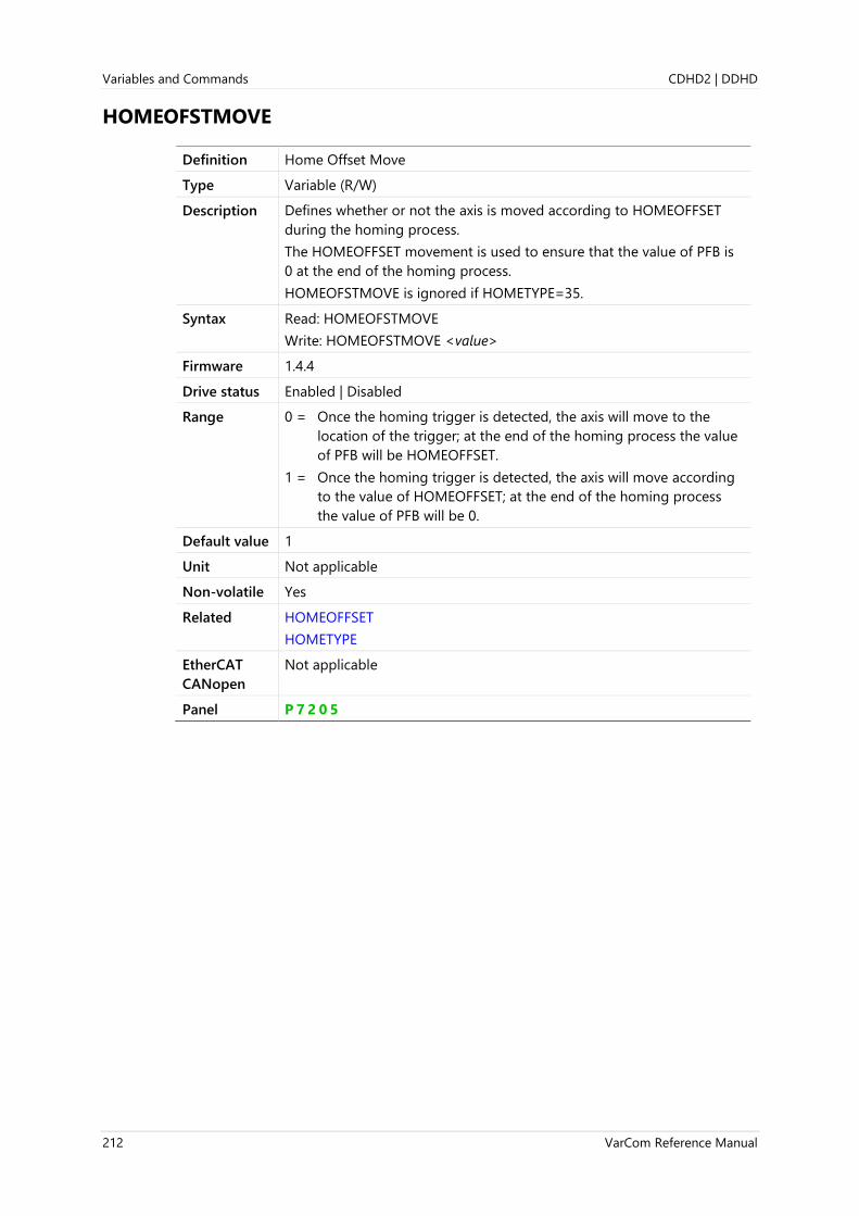
Variables and Commands CDHD2 | DDHD
212 VarCom Reference Manual
HOMEOFSTMOVE
Definition Home Offset Move
Type Variable (R/W)
Description Defines whether or not the axis is moved according to HOMEOFFSET
during the homing process.
The HOMEOFFSET movement is used to ensure that the value of PFB is
0 at the end of the homing process.
HOMEOFSTMOVE is ignored if HOMETYPE=35.
Syntax Read: HOMEOFSTMOVE
Write: HOMEOFSTMOVE <value>
Firmware 1.4.4
Drive status Enabled | Disabled
Range 0 = Once the homing trigger is detected, the axis will move to the
location of the trigger; at the end of the homing process the value
of PFB will be HOMEOFFSET.
1 = Once the homing trigger is detected, the axis will move according
to the value of HOMEOFFSET; at the end of the homing process
the value of PFB will be 0.
Default value 1
Unit Not applicable
Non-volatile Yes
Related HOMEOFFSET
HOMETYPE
EtherCAT
CANopen
Not applicable
Panel P 7 2 0 5

CDHD2 | DDHD Variables and Commands
VarCom Reference Manual 213
HOMESPEED1
Definition Homing Speed 1 - Switch Search
Type Variable (R/W)
Description The initial velocity used in the homing process during the search for
limit switches, home switches, and hard stops.
HOMESPEED1 is defined according to the units currently in effect.
Syntax Read: HOMESPEED1
Write: HOMESPEED1<value>
Firmware 1.2.12
Drive status Disabled
Range 1 [rpm] to VMAX
Default value If MOTORTYPE 0 (Rotary):
If UNITSROTVEL 0 = 1.166
If UNITSROTVEL 1 = 100
If UNITSROTVEL 2 = 600
If MOTORTYPE 2 (Linear):
UNITSLINVEL 1 = 53.333
Unit If MOTORTYPE 0 (Rotary):
If UNITSROTVEL 0 = rps
If UNITSROTVEL 1 = rpm
If UNITSROTVEL 2 = deg/s
If MOTORTYPE 2 (Linear):
UNITSLINVEL 1 = mm/s
Non-volatile Yes
Related HOMETYPE
EtherCAT
CANopen
6099h, sub-index 1
Panel P 7 2 0 6
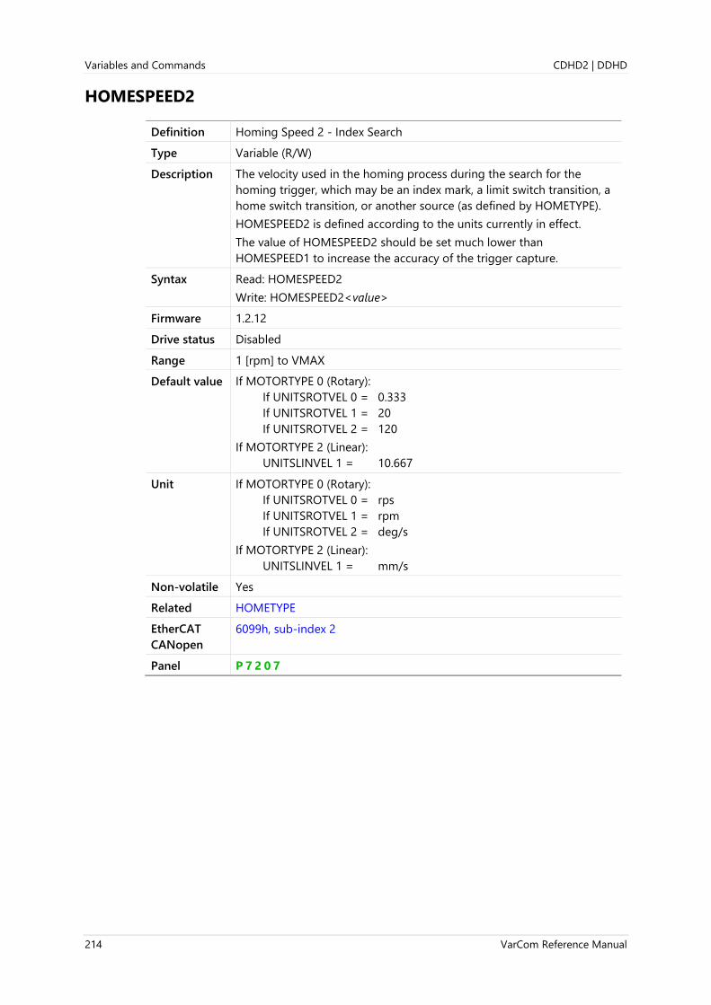
Variables and Commands CDHD2 | DDHD
214 VarCom Reference Manual
HOMESPEED2
Definition Homing Speed 2 - Index Search
Type Variable (R/W)
Description The velocity used in the homing process during the search for the
homing trigger, which may be an index mark, a limit switch transition, a
home switch transition, or another source (as defined by HOMETYPE).
HOMESPEED2 is defined according to the units currently in effect.
The value of HOMESPEED2 should be set much lower than
HOMESPEED1 to increase the accuracy of the trigger capture.
Syntax Read: HOMESPEED2
Write: HOMESPEED2<value>
Firmware 1.2.12
Drive status Disabled
Range 1 [rpm] to VMAX
Default value If MOTORTYPE 0 (Rotary):
If UNITSROTVEL 0 = 0.333
If UNITSROTVEL 1 = 20
If UNITSROTVEL 2 = 120
If MOTORTYPE 2 (Linear):
UNITSLINVEL 1 = 10.667
Unit If MOTORTYPE 0 (Rotary):
If UNITSROTVEL 0 = rps
If UNITSROTVEL 1 = rpm
If UNITSROTVEL 2 = deg/s
If MOTORTYPE 2 (Linear):
UNITSLINVEL 1 = mm/s
Non-volatile Yes
Related HOMETYPE
EtherCAT
CANopen
6099h, sub-index 2
Panel P 7 2 0 7

CDHD2 | DDHD Variables and Commands
VarCom Reference Manual 215
HOMESTATE
Definition Homing Status
Type Variable (R)
Description Indicates the state of the homing process.
HOMESTATE 0 indicates homing is idle. Use HOMECMD 0 (abort
homing) to reset.
Any HOMESTATE value other than 0, 24 or 26 indicates homing is in
progress or stuck; reset if necessary.
Syntax HOMESTATE
Firmware 1.2.12
Drive status Enabled | Disabled
Range 0 = Homing idle
24= Homing successful
26= Homing failed
any other value = Homing in progress
Default value 0
Unit Not applicable
Non-volatile No
Related HOMETYPE
EtherCAT
CANopen
2090h, sub-index 0
Panel P 7 2 0 7

Variables and Commands CDHD2 | DDHD
216 VarCom Reference Manual
HOMETYPE
Definition Homing Type
Type Variable (R/W)
Description Gets/sets a value that defines the type of homing process that will be
performed.
HOMETYPE defines when direction of motion is reversed during
homing, the homing trigger (e.g., switch, index), and other conditions.
Homing types 1 through 14, 17 through 30 and 33 through 35 are
according to CiA 402.
Additional homing types have been defined per customer requests.
Homing on index mark can be used with resolver, absolute single turn
encoder, and absolute multi-turn encoder motor feedback (HOMETYPE
1-14, 33, 34, -8, -12, -33, -34, -40, -44, -65, -66, -97, -98). The location of
the feedback index mark is where the motor mechanical angle
(MECHANGLE) is 0.
To achieve greater accuracy of the homing procedure (i.e., minimum
PFB counts from MECHANGLE 0), reduce the value of HOMESPEED2.
Note When Gantry Difference mode is active (GANTRYMODE 2) and Gantry
Type is Rigid (GANTRYTYPE 0), HOMETYPE must be set to 35.
Syntax Read: HOMETYPE
Write: HOMETYPE <value>
Firmware 1.2.12
Drive status Enabled | Disabled
Range 1 = Homing on first index mark after disengaging from negative limit.
2 = Homing on first index mark after disengaging from positive limit.
3 = Homing on first index mark after disengaging from home switch
(home switch at positive travel).
4 = Homing on first index mark after engaging home switch (home
switch at positive travel).
5 = Homing on first index mark after disengaging from home switch
(home switch at negative travel).
6 = Homing on first index mark after engaging home switch (home
switch at negative travel).
7 = Homing on first index mark after disengaging from negative side
of home switch (home switch at middle of travel); initial move
positive.
8 = Homing on first index mark after engaging negative side of home
switch (home switch at middle of travel); initial move positive.
9 = Homing on first index mark after engaging positive side of home
switch (home switch at middle of travel); initial move positive.
10 = Homing on first index mark after disengaging from positive side of
home switch (home switch at middle of travel); initial move
positive.
11 = Homing on first index mark after disengaging from positive side of
home switch (home switch at middle of travel); initial move
negative.

CDHD2 | DDHD Variables and Commands
VarCom Reference Manual 217
12 = Homing on first index mark after engaging positive side of home
switch (home switch at middle of travel); initial move negative.
13 = Homing on first index mark after engaging negative side of home
switch (home switch at middle of travel); initial move negative.
14 = Homing on first index mark after disengaging from negative side
of home switch (home switch at middle of travel); initial move
negative.
5 = Reserved
16 = Reserved
17 = Homing on falling edge of negative limit.
18 = Homing on falling edge of positive limit.
19 = Homing on falling edge of home switch (home switch at positive
travel).
20 = Homing on rising edge of home switch (home switch at positive
travel).
21 = Homing on falling edge of home switch (home switch at negative
travel).
22 = Homing on rising edge of home switch (home switch at negative
travel).
23 = Homing on negative side falling edge of home switch (home
switch at middle of travel); initial move positive.
24 = Homing on negative side rising edge of home switch (home switch
at middle of travel); initial move positive.
25 = Homing on positive side rising edge of home switch (home switch
at middle of travel); initial move positive.
26 = Homing on positive side falling edge of home switch (home switch
at middle of travel); initial move positive.
27 = Homing on positive side falling edge of home switch (home switch
at middle of travel); initial move negative.
28 = Homing on positive side rising edge of home switch (home switch
at middle of travel); initial move negative.
29 = Homing on negative side rising edge of home switch; initial move
negative.
30 = Homing on negative side falling edge of home switch (home
switch at middle of travel); initial move negative.
31 = Reserved
32 = Reserved
33 = Homing on index mark, moving negative.
34 = Homing on index mark, moving positive.
35 = Declare present position as home. (PFB reading after homing will
always be HOMEOFFSET regardless of HOMEOFSTMOVE setting).
-8 = Homing on first index mark after engaging negative side of home
switch; initial move positive, retract upon first contact with home
switch edge.
-9 = Homing on first index mark after engaging positive side of home
switch; initial move positive; if engaging positive limit switch then
stop and issue failure indication.

Variables and Commands CDHD2 | DDHD
218 VarCom Reference Manual
-10 = Homing on first index mark after disengaging from positive side
of home switch; initial move positive; if engaging positive limit
switch then stop and issue failure indication.
-12 = Homing on first index mark after engaging positive side of
home switch; initial move negative, retract upon first contact with
home switch edge.
-13 = Homing on first index mark after engaging negative side of
home switch; initial move negative; if engaging negative limit
switch then stop and issue failure indication.
-14 = Homing on first index mark after disengaging from negative
side of home switch; initial move negative; if engaging negative
limit switch then stop and issue failure indication.
-24 = Homing on negative side rising edge of home switch; initial
move positive, retract upon first contact with home switch edge.
-26 = Homing on positive side falling edge of home switch; initial
move positive; if engaging positive limit switch then stop and issue
failure indication.
-28 = Homing on positive side rising edge of home switch; initial
move negative, retract upon first contact with home switch edge.
-30 = Homing on negative side falling edge of home switch; initial
move negative; if engaging negative limit switch then stop and
issue failure indication.
-33 = Homing on index mark after direction reversal on hard stop;
initial move negative.
-34 = Homing on index mark after direction reversal on hard stop;
initial move positive.
-40 = Homing on first index mark after engaging negative side of
home switch; initial move positive; reverse direction on hard stop.
-44 = Homing on first index mark after engaging positive side of
home switch; initial move negative; reverse direction on hard stop.
-56 = Homing on negative side rising edge of home switch; initial
move positive; reverse direction on hard stop; retract upon first
contact with home-switch edge.
-60 = Homing on positive side rising edge of home switch; initial
move negative; reverse direction on hard stop, retract upon first
contact with home switch edge.
-65 = Homing on index mark; initial move negative; if index mark not
found reverse direction on hard stop.
-66 = Homing on index mark; initial move positive; if index mark not
found reverse direction on hard-stop.
-97 = Homing on index mark; initial move negative; if index mark not
found reverse direction on negative limit switch.
-98 = Homing on index mark; initial move positive; if index mark not
found reverse direction on positive limit switch.
-125 = Homing on hard stop at negative end of travel.
-126 = Homing on hard stop at positive end of travel.
Default value 1
Unit Not applicable

CDHD2 | DDHD Variables and Commands
VarCom Reference Manual 219
Non-volatile Yes
Related HOMEACC
HOMECMD
HOMEOFFSET
HOMEOFSTMOVE
HOMESPEED1
HOMESPEED2
HOMESTATE
EtherCAT
CANopen
6098h, sub-index 0
Panel P 7 2 0 0

Variables and Commands CDHD2 | DDHD
220 VarCom Reference Manual
HSAVE
Definition Save Parameters to Encoder EEPROM
Type Command
Description Writes the current values of MPHASE and PFBOFFSET to the
EnDat/HIPERFACE encoder memory. These parameters will be loaded
after the next power up or feedback initialization.
The command HSAVE 1 performs the same function as HSAVE, but
prevents the (possibly incorrect) parameter values from being loaded
from the encoder memory at the next power up or feedback
initialization; instead, the encoder will be initialized with parameters
values from drive memory.
Syntax HSAVE
Firmware 1.15.xx
Drive status Enabled | Disabled
Range Not applicable
Default value Not applicable
Unit Not applicable
Non-volatile No
Related FEEDBACKTYPE
MPHASE
PFBOFFSET
EtherCAT
CANopen
Not applicable

CDHD2 | DDHD Variables and Commands
VarCom Reference Manual 221
HWPEXT
Definition Hardware Position External
Type Variable (R)
Description Indicates the position as measured by an external feedback device.
HWPEXT displays a valid value only when the secondary encoder input
is in use while Gearing operation mode (GEARMODE) is enabled.
Note The HWPEXT/PCMD ratio is not maintained under the following
condition:
GEAROUT=1
GEARIN>5000
No warning is issued.
Note When operating in Gearing mode (OPMODE 4), it may be useful to zero
the measured position of the master axis by means of the command
HWPEXT 0.
HWPEXT 0 stores the position in an offset variable, and subsequently
subtracts the offset value from all measured positions.
Syntax HWPEXT
Firmware 1.0.6
Drive status Enabled | Disabled
Range 0 to 65535
Default value Not applicable
Unit counts
Non-volatile No
Related GEARMODE
PCMD
XENCRES
EtherCAT
CANopen
2064h, sub-index 0
Panel P 2 1 0 0
d 0 0 1 4

Variables and Commands CDHD2 | DDHD
222 VarCom Reference Manual
HWPEXTCNTRLR
Definition Hardware Position External (FPGA)
Type Variable (R)
Description Indicates the position as measured by an external feedback device
(FPGA); 32-bit counter of the pulse and direction input from the
controller interface connector.
Syntax HWPEXTCNTRLR
Firmware 1.3.2
Drive status Enabled | Disabled
Range Not applicable
Default value Not applicable
Unit Count
Non-volatile No
Example -->hwpextcntrlr
4294943248 [Counts]
Related GEARINMODE
GEARMODE
HWPEXT
HWPEXTMACHN
EtherCAT
CANopen
2182h, sub-index 0
Panel P 2 1 0 1
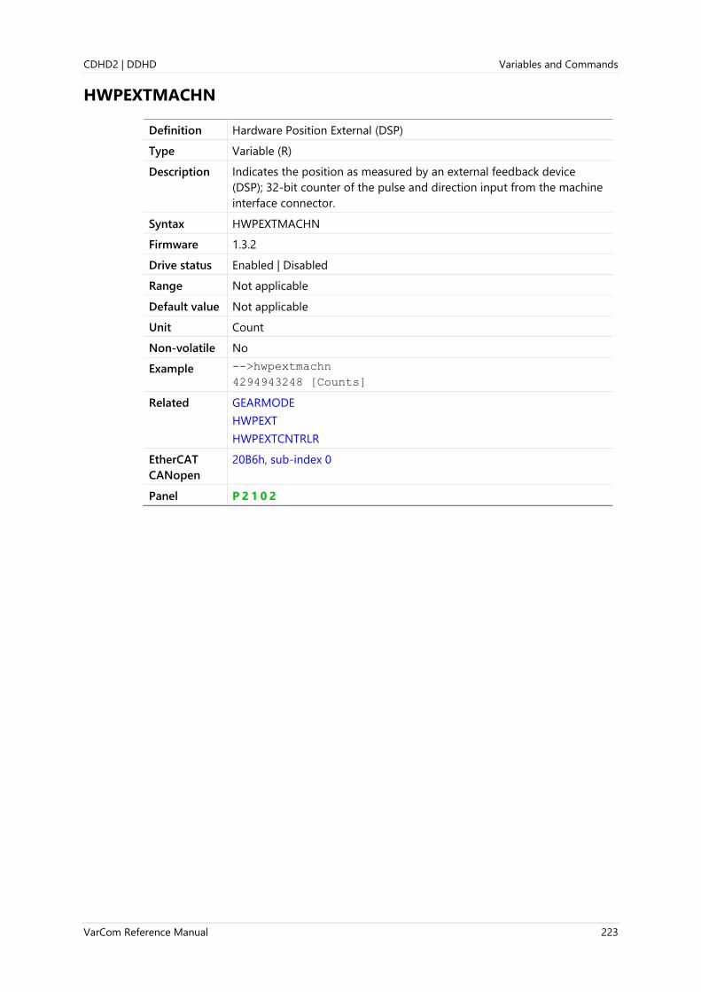
CDHD2 | DDHD Variables and Commands
VarCom Reference Manual 223
HWPEXTMACHN
Definition Hardware Position External (DSP)
Type Variable (R)
Description Indicates the position as measured by an external feedback device
(DSP); 32-bit counter of the pulse and direction input from the machine
interface connector.
Syntax HWPEXTMACHN
Firmware 1.3.2
Drive status Enabled | Disabled
Range Not applicable
Default value Not applicable
Unit Count
Non-volatile No
Example -->hwpextmachn
4294943248 [Counts]
Related GEARMODE
HWPEXT
HWPEXTCNTRLR
EtherCAT
CANopen
20B6h, sub-index 0
Panel P 2 1 0 2

Variables and Commands CDHD2 | DDHD
224 VarCom Reference Manual
HWPOS
Definition Hardware Position
Type Variable (R)
Description Indicates the position, as measured by the feedback device.
Syntax HWPOS
Firmware 1.0.6
Drive status Enabled | Disabled
Range Not applicable. Depends upon the feedback device.
Default value Not applicable
Unit Not applicable
Non-volatile No
Related ELECTANGLE
FEEDBACKTYPE
MECHANGLE
MENCRES
MENCTYPE
MRESPOLES
CANopen 2065h, sub-index 0
Panel P 2 0 2 1

CDHD2 | DDHD Variables and Commands
VarCom Reference Manual 225
I
Definition Motor Current
Type Variable (R)
Description Indicates the motor current (sinusoidal peak).
Syntax I
Firmware 1.0.6
Drive status Enabled | Disabled
Range Not applicable
Default value Not applicable
Unit A
Non-volatile No
Related ICMD
ID
IFOLD
ILIM
IMAX
IU
EtherCAT
CANopen
6078h, sub-index 0
Panel P 1 3 1 4
d 0 0 0 3

Variables and Commands CDHD2 | DDHD
226 VarCom Reference Manual
ICMD
Definition Current Command
Type Variable (R)
Description Indicates the current command, which is generated either directly
(EtherCAT/CANopen, serial or analog reference command), or as output
of the position or velocity controller.
Syntax ICMD
Firmware 1.0.6
Drive status Enabled | Disabled
Range Not applicable
Default value Not applicable
Unit A
Non-volatile No
Related I
ID
IFOLD
ILIM
IMAX
IU
EtherCAT
CANopen
6074h, sub-index 0
Panel P 1 3 1 5

CDHD2 | DDHD Variables and Commands
VarCom Reference Manual 227
ID
Definition Current D Axis
Type Variable (R)
Description In vector control, indicates the value perpendicular to IQ.
Syntax ID
Firmware 1.0.6
Drive status Enabled | Disabled
Range Not applicable
Default value Not applicable
Unit A
Non-volatile No
Related I
ILIM
IMAX
IQ
IU
EtherCAT
CANopen
2066h, sub-index 0
Panel P 1 3 1 6

Variables and Commands CDHD2 | DDHD
228 VarCom Reference Manual
IDENT
Definition Identification Command
Type Command
Description Activates a procedure that identifies the mechanical characteristics of
the system to which the motor is connected, thereby allowing the user
to design an appropriate motion control strategy.
This command improves on the RECORD command in the following
ways:
⚫ Enables simultaneous recording of up to four sample rates and up
to four PRB amplitudes, and returns results with one GET command.
⚫ Eliminates the need for PRBMODE, PRBPARAM and RECORD.
⚫ If the drive is disabled or the recording is aborted while the
identification procedure is in progress, PRB will be disabled, and
remain disabled even if the drive is re-enabled.
When the IDENT command is issued with arguments, the identification
procedure is activated and waits for a RECTRIG command (similar to
RECORD) to initiate recording and turn on the PRB.
The recording is performed with up to four different PRB amplitudes
and up to four different gaps
The first quarter of the recording is executed with amp1 and gap1, the
second quarter with amp2 and gap2, the third quarter with amp3 and
gap3, and the forth quarter with amp4 and gap4. In each quarter exactly
1024 points are recorded, totaling 4096 points for the entire recording.
If less than eight arguments are defined, the IDENT command uses
default values for the undefined arguments: 0 for PRB amplitudes and 1
for the gaps.
The IDENT command also sets the following parameters:
⚫ The variables to be recorded: ICMD, PFB and VINT
⚫ PRBMODE=1 (PRB generator active only during recording)
⚫ PRBPARAM=1 (PRB signal type; white noise)
Syntax IDENT [<amp1> <gap1> <amp2> <gap2> <amp3> <gap3> <amp4>
<gap4>]
amp: sets the excitation amplitude of the PRB (of ICMD)
gap: sets the recording intervals
Firmware 2.15.x
Drive status Enabled | Disabled
Range amp: 0 to IMAX
gap: 1 to 1000000
Default value Not applicable
Unit amp: ampere (A)
gap: multiples of 31.25 µs
Non-volatile Not applicable
Example ident 0.5 64

CDHD2 | DDHD Variables and Commands
VarCom Reference Manual 229
Example ident 0.5 32 0.15 16 0.5 30
Example opmode 2
en ident 0.7 64 0.5 32 0.1 16 0.3 32
rectrig "imm
Related GET
ICMD
IDENTOFF
IDENTST
PFB
PRBMODE
PRBPARAM
RECORD
RECTRIG
VINT
EtherCAT
CANopen
Not applicable

Variables and Commands CDHD2 | DDHD
230 VarCom Reference Manual
IDENTOFF
Definition Stop Identification Recording
Type Command
Description Stops the system identification procedure and switches the status to
Idle.
However, if IDENTOFF command is issued while the identification
procedure is in progress (“In action”), the procedure is aborted and the
status switches to Fail.
The RECORD command cannot be issued while IDENT is active. To
enable RECORD functionality before the identification procedure is
completed, use the IDENTOFF command; for example:
IDENT 0.7 64
IDENTOFF
RECORD 16 2048 "icmd // no error here…
Syntax IDENTOFF
Firmware 2.15.x
Drive status Enabled | Disabled
Range Not applicable
Default value Not applicable
Unit Not applicable
Non-volatile Not applicable
Related IDENT
IDENTST
EtherCAT
CANopen
Not applicable
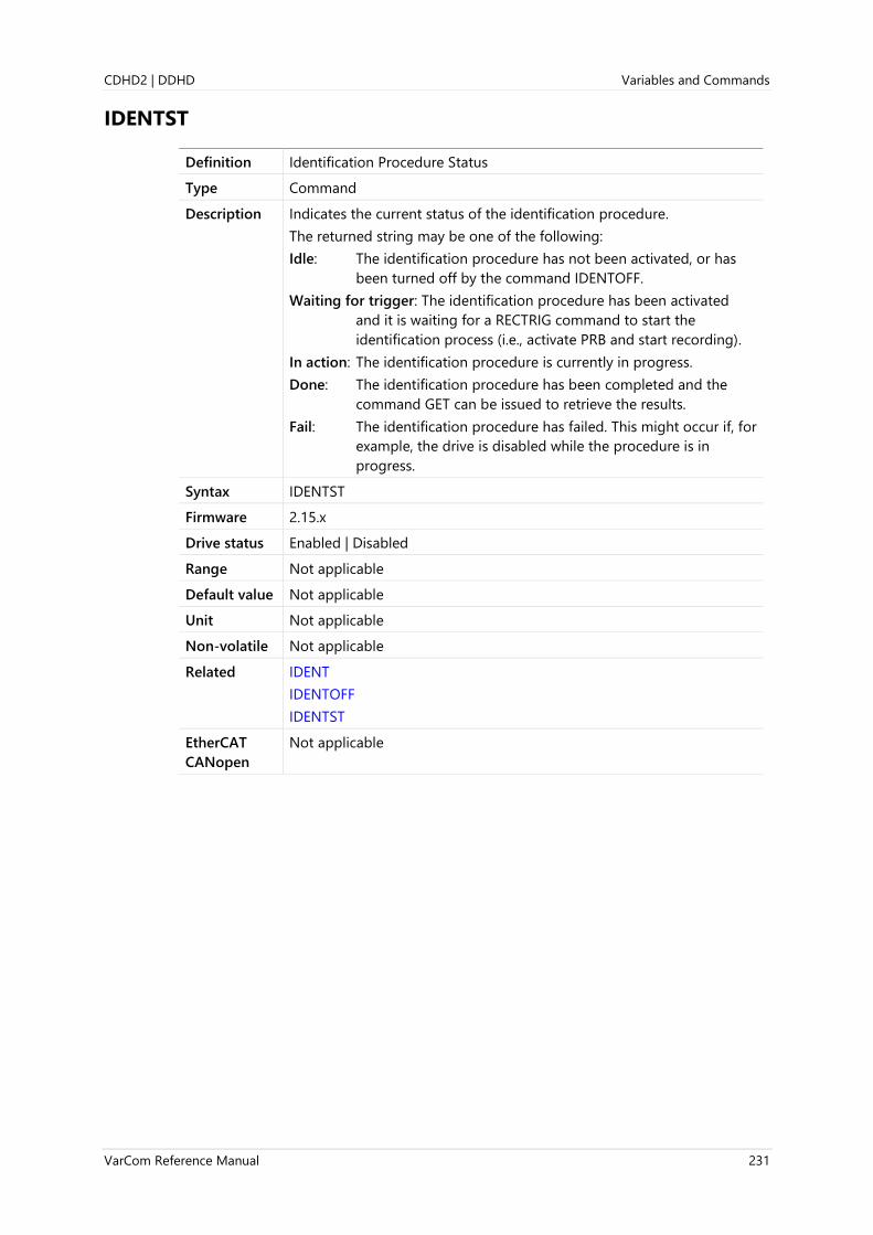
CDHD2 | DDHD Variables and Commands
VarCom Reference Manual 231
IDENTST
Definition Identification Procedure Status
Type Command
Description Indicates the current status of the identification procedure.
The returned string may be one of the following:
Idle: The identification procedure has not been activated, or has
been turned off by the command IDENTOFF.
Waiting for trigger: The identification procedure has been activated
and it is waiting for a RECTRIG command to start the
identification process (i.e., activate PRB and start recording).
In action: The identification procedure is currently in progress.
Done: The identification procedure has been completed and the
command GET can be issued to retrieve the results.
Fail: The identification procedure has failed. This might occur if, for
example, the drive is disabled while the procedure is in
progress.
Syntax IDENTST
Firmware 2.15.x
Drive status Enabled | Disabled
Range Not applicable
Default value Not applicable
Unit Not applicable
Non-volatile Not applicable
Related IDENT
IDENTOFF
IDENTST
EtherCAT
CANopen
Not applicable
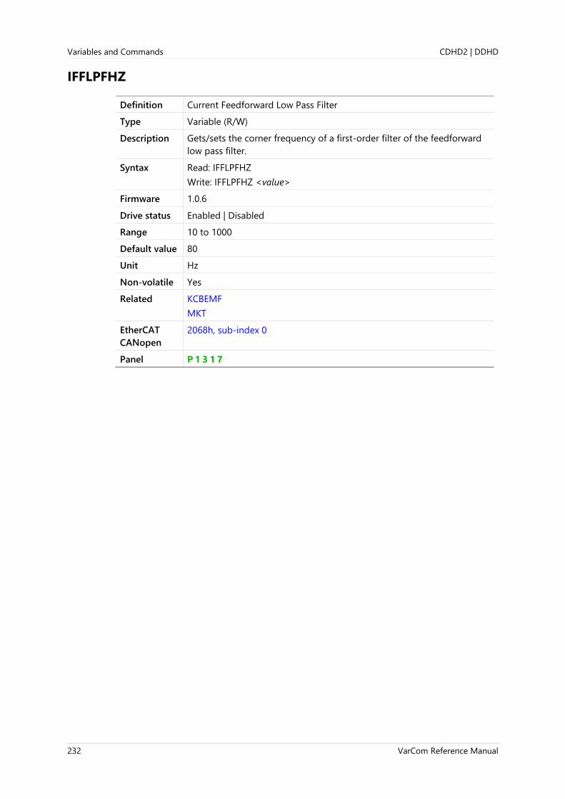
Variables and Commands CDHD2 | DDHD
232 VarCom Reference Manual
IFFLPFHZ
Definition Current Feedforward Low Pass Filter
Type Variable (R/W)
Description Gets/sets the corner frequency of a first-order filter of the feedforward
low pass filter.
Syntax Read: IFFLPFHZ
Write: IFFLPFHZ <value>
Firmware 1.0.6
Drive status Enabled | Disabled
Range 10 to 1000
Default value 80
Unit Hz
Non-volatile Yes
Related KCBEMF
MKT
EtherCAT
CANopen
2068h, sub-index 0
Panel P 1 3 1 7

CDHD2 | DDHD Variables and Commands
VarCom Reference Manual 233
IFOLD
Definition Drive Foldback Current Limit
Type Variable (R)
Description Indicates the current limit derived from the foldback mechanism. A
foldback condition occurs when IFOLD drops below ILIM.
This variable is useful for checking how close the current is to the
foldback limit.
Syntax IFOLD
Firmware 1.0.6
Drive status Enabled | Disabled
Range 0 to 300
Default value Not applicable
Unit A
Non-volatile No
Related DICONT
FOLD
IFOLDFTHRESH
IFOLDWTHRESH
ILIM
EtherCAT
CANopen
2069h, sub-index 0
Panel P 7 0 0 3

Variables and Commands CDHD2 | DDHD
234 VarCom Reference Manual
IFOLDFTHRESH
Definition Drive Foldback Fault Threshold
Type Variable (R/W)
Description Gets/sets the current threshold level for declaring a fault due to
foldback.
The drive foldback threshold fault is declared when IFOLD drops below
IFOLDFTHRESH.
Syntax Read: IFOLDFTHRESH
Write: IFOLDFTHRESH <value>
Firmware 1.0.6
Drive status Enabled | Disabled
Range 0 to 300
Default value Not applicable
Unit A
Non-volatile Yes
Related DICONT
FOLD
IFOLD
IFOLDWTHRESH
ILIM
EtherCAT
CANopen
206Ah, sub-index 0
Panel P 7 0 0 4

CDHD2 | DDHD Variables and Commands
VarCom Reference Manual 235
IFOLDWTHRESH
Definition Drive Foldback Warning Threshold
Type Variable (R/W)
Description Gets/sets the current threshold level for declaring a warning due to
foldback.
The drive foldback threshold warning is declared when IFOLD drops
below IFOLDWTHRESH.
Syntax Read: IFOLDWTHRESH
Write: IFOLDWTHRESH <value>
Firmware 1.0.6
Drive status Enabled | Disabled
Range 0 to 300
Default value Not applicable
Unit A
Non-volatile Yes
Related DICONT
FOLD
IFOLD
IFOLDFTHRESH
ILIM
EtherCAT
CANopen
206Bh, sub-index 0
Panel P 7 0 0 5

Variables and Commands CDHD2 | DDHD
236 VarCom Reference Manual
IGNOREBATTFLT
Definition Ignore Absolute Encoder Battery Fault
Type Variable (R/W)
Description Defines whether the drive will respond to an encoder battery voltage
warning or fault.
Allows a multi-turn absolute encoder to be used without a backup
battery, as a single-turn absolute encoder.
Syntax Read: IGNOREBATTFLT
Write: IGNOREBATTFLT <value>
Firmware 1.41.x
Drive status Enabled | Disabled
Range 0 = Drive detects and responds to encoder battery fault.
1 = Drive ignores encoder battery fault (absolute multi-turn position
will not be retained after a power cycle).
Default value 0
Unit Not applicable
Non-volatile Yes
Related MTTURNRESET
EtherCAT
CANopen
2187h, sub-index 0

CDHD2 | DDHD Variables and Commands
VarCom Reference Manual 237
IGNOREBRKFLT
Definition Ignore Power Brake Fault
Type Variable (R/W)
Description Note: Applicable only to CDHD2 400/480 VAC drives,
3A, 6A, 12A, 30A
Note Previously IGNOREPWRBRK in earlier firmware versions.
Syntax Read: IGNOREBRKFLT
Write: IGNOREBRKFLT <value>
Firmware 1.20.6
Drive status Enabled | Disabled
Range 0 = Drive ignores brake fault indication
1 = Drive ignores STO fault indication
Default value 0
Unit Not applicable
Non-volatile Yes
Related ST
EtherCAT
CANopen
Not applicable
Panel P 7 3 0 5

Variables and Commands CDHD2 | DDHD
238 VarCom Reference Manual
IGNOREPDLB
Definition Ignore Pulse and Direction Line Break
Type Variable (R/W)
Description Defines whether drive responds to or ignores Pulse and Direction line
break.
Syntax Read: IGNOREPDLB
Write: IGNOREPDLB <value>
Firmware 1.15.xx
Drive status Enabled | Disabled
Range 0 = Drive responds to P&D line break when drive enabled or disabled
1 = Drive responds to P&D line break only when drive enabled
Default value 0
Unit Not applicable
Non-volatile Yes
Related GEARMODE
EtherCAT
CANopen
Not applicable

CDHD2 | DDHD Variables and Commands
VarCom Reference Manual 239
IGRAV
Definition Gravity Compensation Constant
Type Variable (R/W)
Description Gets/sets the value of the gravity compensation constant.
IGRAV is added to the current loop command to compensate for gravity
or similar constant interference.
Syntax Read: IGRAV
Write: IGRAV <value>
Firmware 1.0.6
Drive status Enabled | Disabled
Range ±DIPEAK
Default value 0.000
Unit A
Non-volatile Yes
Related I
FRICINEG
FRICIPOS
ILIM
DIPEAK
EtherCAT
CANopen
206Ch, sub-index 0
Panel P 1 3 1 8
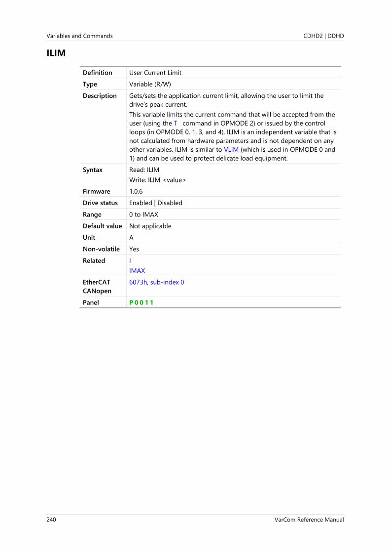
Variables and Commands CDHD2 | DDHD
240 VarCom Reference Manual
ILIM
Definition User Current Limit
Type Variable (R/W)
Description Gets/sets the application current limit, allowing the user to limit the
drive’s peak current.
This variable limits the current command that will be accepted from the
user (using the T command in OPMODE 2) or issued by the control
loops (in OPMODE 0, 1, 3, and 4). ILIM is an independent variable that is
not calculated from hardware parameters and is not dependent on any
other variables. ILIM is similar to VLIM (which is used in OPMODE 0 and
1) and can be used to protect delicate load equipment.
Syntax Read: ILIM
Write: ILIM <value>
Firmware 1.0.6
Drive status Enabled | Disabled
Range 0 to IMAX
Default value Not applicable
Unit A
Non-volatile Yes
Related I
IMAX
EtherCAT
CANopen
6073h, sub-index 0
Panel P 0 0 1 1
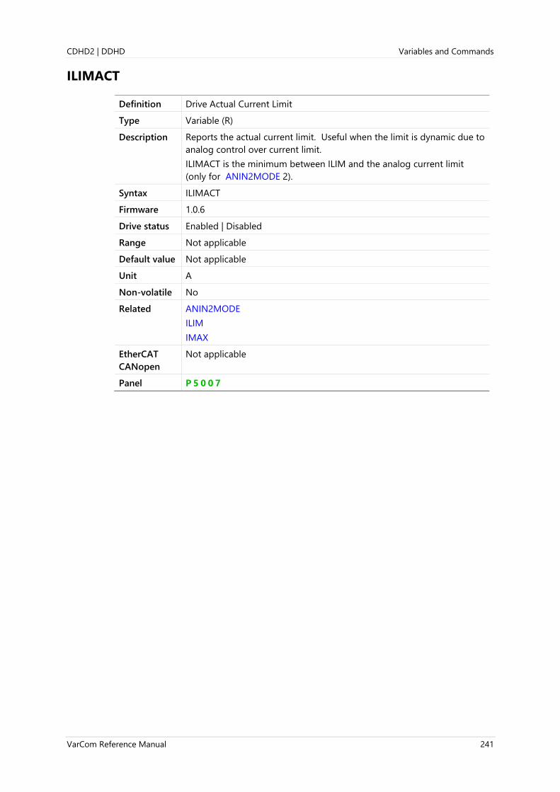
CDHD2 | DDHD Variables and Commands
VarCom Reference Manual 241
ILIMACT
Definition Drive Actual Current Limit
Type Variable (R)
Description Reports the actual current limit. Useful when the limit is dynamic due to
analog control over current limit.
ILIMACT is the minimum between ILIM and the analog current limit
(only for ANIN2MODE 2).
Syntax ILIMACT
Firmware 1.0.6
Drive status Enabled | Disabled
Range Not applicable
Default value Not applicable
Unit A
Non-volatile No
Related ANIN2MODE
ILIM
IMAX
EtherCAT
CANopen
Not applicable
Panel P 5 0 0 7

Variables and Commands CDHD2 | DDHD
242 VarCom Reference Manual
IMAX
Definition Maximum Current for Drive and Motor
Type Variable (R)
Description Displays the maximum current limit for a drive and motor combination.
Syntax IMAX
Firmware 1.0.6
Drive status Enabled | Disabled
Range Not applicable
Default value Not applicable
Unit A
Non-volatile No
Related DIPEAK
I
ILIM
MIPEAK
EtherCAT
CANopen
20F0h, sub-index 0
Panel P 1 3 1 9

CDHD2 | DDHD Variables and Commands
VarCom Reference Manual 243
IN
Definition Input Status
Type Variable (R)
Description Gets the state of a digital input.
Syntax IN <input#>
Firmware 1.0.6
Drive status Enabled | Disabled
Range input# = 1 to 11
0 = Input off
1 = Input on
Default value Not applicable
Unit Not applicable
Non-volatile No
Example -->IN 1
0
Related ININV
INMODE
INPUTS
EtherCAT
CANopen
60FDh, sub-index 0
Panel d 0 0 0 4 (inputs 1 to 10)
d 0 0 0 5 (input 11)

Variables and Commands CDHD2 | DDHD
244 VarCom Reference Manual
IN32OPMODES
Definition Operation Mode Change Input Level
Type Variable (R/W)
Description Enables the operation mode to be changed on-the-fly, even while drive
is enabled.
IN32OPMODES holds a 16-bit value.
The high byte defines the operation mode to be activated upon a high
level of the digital input defined in INMODE <i#> 32.
The low byte defines the operation to be activated upon a low level of
the digital input defined in INMODE <i#> 32.
For example:
-->INMODE 8 32
-->IN32OPMODES h0403
A high level of digital input 8 sets OPMODE 4.
A low level of digital input 8 sets OPMODE 3.
Syntax Read: IN32OPMODES
Write: IN32OPMODES <value>
Firmware 1.40.0
Drive status Enabled | Disabled
Range 0 to 2056 (0 … 0x808)
Default value 0
Unit Not applicable
Non-volatile Yes
Related IN32SWITCH
INMODE
OPMODE
OPMODESWITCH
EtherCAT
CANopen
Not applicable
Panel P 4 0 3 7

CDHD2 | DDHD Variables and Commands
VarCom Reference Manual 245
IN32SWITCH
Definition Operation Mode Change Resume Motion
Type Variable (R/W)
Description Defines if and how motion resumes after switching back to an OPMODE
that corresponds to a specific input level.
Note When switching back to OPMODE 4: The gearing position will be
restored only if bit 2 in the GEARLIMITSMODE parameter is set to 1;
otherwise the drive will be unable to perform any profile according to
ACC, DEC or VLIM.
Syntax Read: IN32SWITCH
Write: IN32SWITCH <value>
Firmware 1.40.0
Drive status Enabled | Disabled
Range 0 to 3
Range 0 = No further action will occur after switching the operation mode via
INMODE <i#> 32.
1 = The previous command value will be restored if the digital input
switches back to the OPMODE defined in the low byte of
IN32OPMODES.
2 = The previous command value will be restored if the digital input
switches back to the OPMODE defined in the high byte of
IN32OPMODES.
3 = The previous command value will be restored if the digital input
switches back to the OPMODE defined by either the low or high
byte in IN32OPMODES.
Default value 0
Unit Not applicable
Non-volatile Yes
Related IN32OPMODES
INMODE
OPMODE
OPMODESWITCH
EtherCAT
CANopen
Not applicable
Panel P 4 0 3 8

Variables and Commands CDHD2 | DDHD
246 VarCom Reference Manual
INDEXDURATE
Definition Simulated Encoder Index Pulse Duration
Type Variable (R/W)
Description Gets/sets the duration of the simulated index pulse in the encoder
simulation feature. This function allows users to observe index pulses of
very short durations.
To be used effectively, the duration of the simulated index pulse must
be shorter than the time length of one revolution; otherwise a constant
signal will be generated.
INDEXDURATE 0 = The drive will issue the simulated index pulse
according to the hardware mechanism’s defaults.
Syntax Read: INDEXDURATE
Write: INDEXDURATE <value>
Firmware 1.4.4
Drive status Enabled | Disabled
Range 0 to 100
Default value 0
Unit ms
Non-volatile Yes
Related ENCOUTMODE
ENCOUTRES
ENCOUTZPOS
INDEXST
MENCRES
EtherCAT
CANopen
Not applicable
Panel P 2 0 3 2

CDHD2 | DDHD Variables and Commands
VarCom Reference Manual 247
INDEXPFB
Definition Encoder Index Position Feedback
Type Variable (R)
Description Indicates the position feedback (PFB) captured at the first index
detection after power on.
Syntax INDEXPFB
Firmware 1.0.6
Drive status Enabled | Disabled
Range If MOTORTYPE 0 (Rotary): ±(231 -1) [rev]
If MOTORTYPE 2 (Linear): ±(231 -1) [pitch]
Default value If MOTORTYPE 0 (Rotary):
UNITSROTPOS 0 = 0.309
UNITSROTPOS 1 = 2529.69
UNITSROTPOS 2 = 111.168
If MOTORTYPE 2 (Linear):
UNITSLINPOS 0 = 0.309
UNITSLINPOS 1 = 2529.69
Unit If MOTORTYPE 0 (Rotary):
UNITSROTPOS 0 = rev
UNITSROTPOS 1 = count
UNITSROTPOS 2 = deg
If MOTORTYPE 2 (Linear):
UNITSLINPOS 0 = pitch
UNITSLINPOS 1 = count
UNITSLINPOS 3 = mm
Non-volatile No
Related FEEDBACKTYPE
HWPOS
MENCTYPE
MENCZPOS
PFB
UNITSROTPOS
EtherCAT
CANopen
206Fh, sub-index 0

Variables and Commands CDHD2 | DDHD
248 VarCom Reference Manual
INDEXST
Definition Encoder Index Signal Status
Type Variable (R)
Description Indicates the state of the encoder index signal.
Syntax Read: INDEXST
Write: INDEXST <value>
Firmware 1.4.4
Drive status Enabled | Disabled
Range 0 = Encoder index signal inactive; position not within index
1 = Encoder index signal active; position within index
Default value Not applicable
Unit Not applicable
Non-volatile No
Related ENCOUTMODE
ENCOUTRES
ENCOUTZPOS
INDEXDURATE
MENCRES
EtherCAT
CANopen
Not applicable

CDHD2 | DDHD Variables and Commands
VarCom Reference Manual 249
INFO
Definition Drive Info
Type Command
Description Returns information about the drive.
Syntax INFO
Firmware 1.0.6
Drive status Enabled | Disabled
Range Not applicable
Default value Not applicable
Unit Not applicable
Non-volatile Not applicable
Example info
Digital Servo Drive
---------------------------------------
Drive model number: CDHD-0062A
Peak current : 25.455 A / 18.000 Arms
Continuous current: 8.485 A / 6.000 Arms
Feedback type : sensAR Magnetic Encoder Single Turn
Interface : Unknown
Voltage : 200 V
Product S/N : 000000000000, January 2000
Control board
P/N :
S/N :
HW revision : NA
Eeprom revision : 5
Flash Device ID : Spansion S29GL064S70BHI040
Power board
P/N : PRDr9SPACSMz-06
S/N : D4615-019570
HW revision : 12
Eeprom revision : 5
Firmware Version : 2.15.2a9.0.36
FieldBus Version : EC_5.90.03
ESI Version : H00029005
FPGA Version : 4.20 May 15 2018
Resident Version : 1.3.8
Runtime : 229:13:45
-->
Related DRIVENAME
TRUN
VER
EtherCAT
CANopen
Not applicable

Variables and Commands CDHD2 | DDHD
250 VarCom Reference Manual
ININV
Definition Input Polarity Inversion
Type Variable (R/W)
Description Gets/sets the input polarity of the digital inputs.
ININV i# 0: no inversion is in effect, and the input is considered inactive
when it is pulled low through a connection to digital ground.
ININV i# 1: inversion is in effect, and the switch is considered inactive
when it is open-circuit or pulled high.
Warning:
Make sure ININV=0 for the input that triggers Hold and Resume Motion
(INMODE i# 30). Thus, if the input value is 0 and a wire break occurs, no
unintentional movement will result. Reversing the input logic on this
input is not recommended, and is fully the responsibility of the user.
Syntax Read: ININV <input#>
Write: ININV <input#> <value>
Firmware 1.0.6
Drive status Enabled | Disabled
Range input# = 1 to 11
value:
0 = Input not inverted
1 = Input inverted
Default value 0
Unit Not applicable
Non-volatile Yes
Example -->ininv 1
0
-->ininv 1 1
-->ininv 1
1
-->
Related IN
INMODE
INPUTS
EtherCAT
CANopen
2070h, sub-index 1

CDHD2 | DDHD Variables and Commands
VarCom Reference Manual 251
Panel P 4 0 1 1 Input Inversion (input 1)
P 4 0 1 2 Input Inversion (input 2)
P 4 0 1 3 Input Inversion (input 3)
P 4 0 1 4 Input Inversion (input 4)
P 4 0 1 5 Input Inversion (input 5)
P 4 0 1 6 Input Inversion (input 6)
P 4 0 1 7 Input Inversion (input 7)
P 4 0 1 8 Input Inversion (input 8)
P 4 0 1 9 Input Inversion (input 9)
P 4 0 2 0 Input Inversion (input 10)
P 4 0 2 1 Input Inversion (input 11)
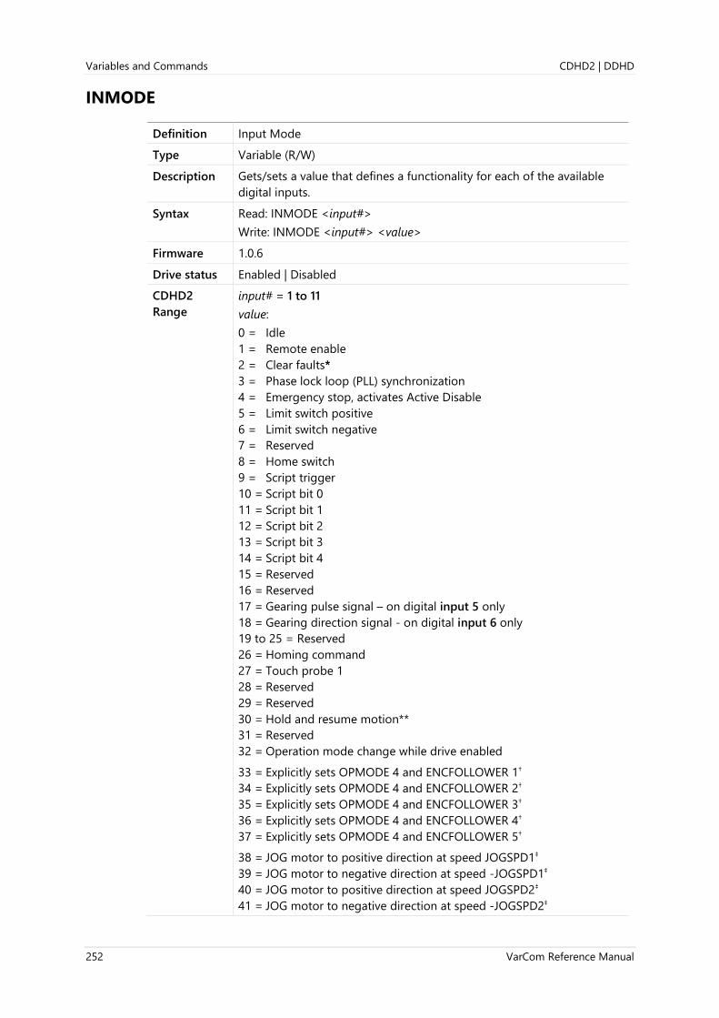
Variables and Commands CDHD2 | DDHD
252 VarCom Reference Manual
INMODE
Definition Input Mode
Type Variable (R/W)
Description Gets/sets a value that defines a functionality for each of the available
digital inputs.
Syntax Read: INMODE <input#>
Write: INMODE <input#> <value>
Firmware 1.0.6
Drive status Enabled | Disabled
CDHD2
Range
input# = 1 to 11
value:
0 = Idle
1 = Remote enable
2 = Clear faults*
3 = Phase lock loop (PLL) synchronization
4 = Emergency stop, activates Active Disable
5 = Limit switch positive
6 = Limit switch negative
7 = Reserved
8 = Home switch
9 = Script trigger
10 = Script bit 0
11 = Script bit 1
12 = Script bit 2
13 = Script bit 3
14 = Script bit 4
15 = Reserved
16 = Reserved
17 = Gearing pulse signal – on digital input 5 only
18 = Gearing direction signal - on digital input 6 only
19 to 25 = Reserved
26 = Homing command
27 = Touch probe 1
28 = Reserved
29 = Reserved
30 = Hold and resume motion**
31 = Reserved
32 = Operation mode change while drive enabled
33 = Explicitly sets OPMODE 4 and ENCFOLLOWER 1†
34 = Explicitly sets OPMODE 4 and ENCFOLLOWER 2†
35 = Explicitly sets OPMODE 4 and ENCFOLLOWER 3†
36 = Explicitly sets OPMODE 4 and ENCFOLLOWER 4†
37 = Explicitly sets OPMODE 4 and ENCFOLLOWER 5†
38 = JOG motor to positive direction at speed JOGSPD1‡
39 = JOG motor to negative direction at speed -JOGSPD1‡
40 = JOG motor to positive direction at speed JOGSPD2‡
41 = JOG motor to negative direction at speed -JOGSPD2‡

CDHD2 | DDHD Variables and Commands
VarCom Reference Manual 253
DDHD Range input# = 1 to 8
value:
0 = Idle
1 = Remote enable*
2 = Clear faults**
3 = Phase lock loop (PLL) synchronization
4 = Emergency stop, activates Active Disable
5 = Limit switch positive
6 = Limit switch negative
7 = Reserved
8 = Home switch
9 = Script trigger
10 = Script bit 0
11 = Script bit 1
12 = Script bit 2
13 = Script bit 3
14 = Script bit 4
15 = Reserved
16 = Reserved
17 = Gearing pulse signal (requires fast input 1 or 3)
18 = Gearing direction signal (requires fast input 2 or 4)
19 to 25 = Reserved
26 = Homing command
27 = Touch probe 1
28 = Touch probe 2
29 = Reserved
30 = Hold and resume motion ***
31 = Reserved
. . .
* Note INMODE <i#> 1
If remote enable is toggled when a drive fault is active, the drive will
clear the fault, provided the fault condition has been removed.
** Note INMODE <i#> 2 will not clear a fault if the condition causing the fault
has not been removed.
To clear a fault using I/Os, REMOTE must be disabled. Therefore, when a
fault occurs, enter the following sequence of commands to prevent the
drive from being reenabled unintentionally before the fault is cleared:
REMOTE 0
INMODE <i#> 2
REMOTE 1
If CLEARFAULTS is used, it will also issue a software disable command
(K) automatically; thus, if all other conditions for activation are present,
the software enable command (EN) will immediately enable the drive.

Variables and Commands CDHD2 | DDHD
254 VarCom Reference Manual
*** Note INMODE <i#> 30:
Defines an input as a Hold and Resume Motion trigger.
When the digital input configured for the Hold/Resume function is
activated, the drive stops a jog movement (in OPMODE 0), or a motion
task (in OPMODE 8), or a running homing procedure (in OPMODE 8).
When the input is released, the drive allows the interrupted motion to
resume.
While in the Hold state, a warning is indicated both on the drive’s digital
display (blinking operation mode) and in response to ST (Hold Mode
Active message).
Requires HOLDMODE=1.
If HOLDMODE=0, the interrupted motion will not resume.
Warning:
Make sure ININV=0 for the input that triggers Hold and Resume
Motion. Thus, if the input value is 0 and a wire break occurs, no
unintentional movement will result.
Reversing the input logic (ININV=1) is not recommended, and is
fully the responsibility of the user.
†Note INMODE <i#> 33|34|35|36|37
Only one digital input should be defined for the encoder following
functionality.
If two or more digital inputs are defined for encoder following and
activated at the same time, the drive will set ENCFOLLOWER=0, and
issue a warning.
If multiple digital inputs defined for encoder following are all inactive at
the same time, the drive will set ENCFOLLOWER=0.
If no digital input is defined for encoder following, the drive will use the
ENCFOLLOWER value from non-volatile memory or from RAM.
‡Note Only one of the digital inputs defined for the jog function should be
activated at a time.
If two or more digital inputs are defined for the jog function and
activated at the same time, the drive will not jog the motor.
CDHD2
Default value
INMODE <input1> = 1
INMODE <input2-11> = 0
DDHD
Default value
INMODE <input1> = 1
INMODE <input2-8> = 0
Unit Not applicable
Non-volatile Yes
Example -->INMODE 1 0
-->INMODE 1
0
-->

CDHD2 | DDHD Variables and Commands
VarCom Reference Manual 255
Related GEARMODE
HOLDMODE
IN
ININV
INPUTS
SYNCSOURCE
EtherCAT
CANopen
20E0h, sub-index 1
Panel P 4 0 0 0 Input Mode (input 1)
P 4 0 0 1 Input Mode (input 2)
P 4 0 0 2 Input Mode (input 3)
P 4 0 0 3 Input Mode (input 4)
P 4 0 0 4 Input Mode (input 5)
P 4 0 0 5 Input Mode (input 6)
P 4 0 0 6 Input Mode (input 7)
P 4 0 0 7 Input Mode (input 8)
P 4 0 0 8 Input Mode (input 9)
P 4 0 0 9 Input Mode (input 10)
P 4 0 1 0 Input Mode (input 11)

Variables and Commands CDHD2 | DDHD
256 VarCom Reference Manual
INPOS
Definition In Position Indication
Type Variable (R)
Description Indicates whether the position error PE is within the allowed tolerance
PEMAX.
INPOS can be used when the drive is in a position operation mode. The
motion command may be generated internally or by external controller.
Syntax INPOS
Firmware 1.0.6
Drive status Enabled | Disabled
Range 0 = Not in position
1 = In position
Default value Not applicable
Unit Not applicable
Non-volatile Yes
Related PEINPOS
PEINPOSTIME
PEMAX
STOPPED
EtherCAT
CANopen
20B5h, sub-index 0

CDHD2 | DDHD Variables and Commands
VarCom Reference Manual 257
INPUTS
Definition Inputs Status
Type Variable (R)
Description Gets the state of all digital inputs.
A header lines identifies each of the inputs.
Syntax INPUTS
Firmware 1.0.6
Drive status Enabled | Disabled
Range 0 = Input off
1 = Input on
Default value Not applicable
Unit Not applicable
Non-volatile No
Example -->INPUTS
1 2 3 4 5 6 7 8 9 10 11
1 0 0 0 0 0 0 0 0 0 0
-->
Related IN
ININV
INMODE
Panel d 0 0 0 4 digital inputs 1 to 10
d 0 0 0 5 digital input 11
EtherCAT
CANopen
Not applicable

Variables and Commands CDHD2 | DDHD
258 VarCom Reference Manual
IQ
Definition Current Q Axis
Type Variable (R)
Description In vector control, indicates the current for the torque.
This value is perpendicular to ID .
Syntax IQ
Firmware 1.0.6
Drive status Enabled | Disabled
Range Not applicable
Default value Not applicable
Unit A
Non-volatile No
Related I
ID
ILIM
IMAX
IU
EtherCAT
CANopen
2067h, sub-index 0
Panel P 1 3 2 0
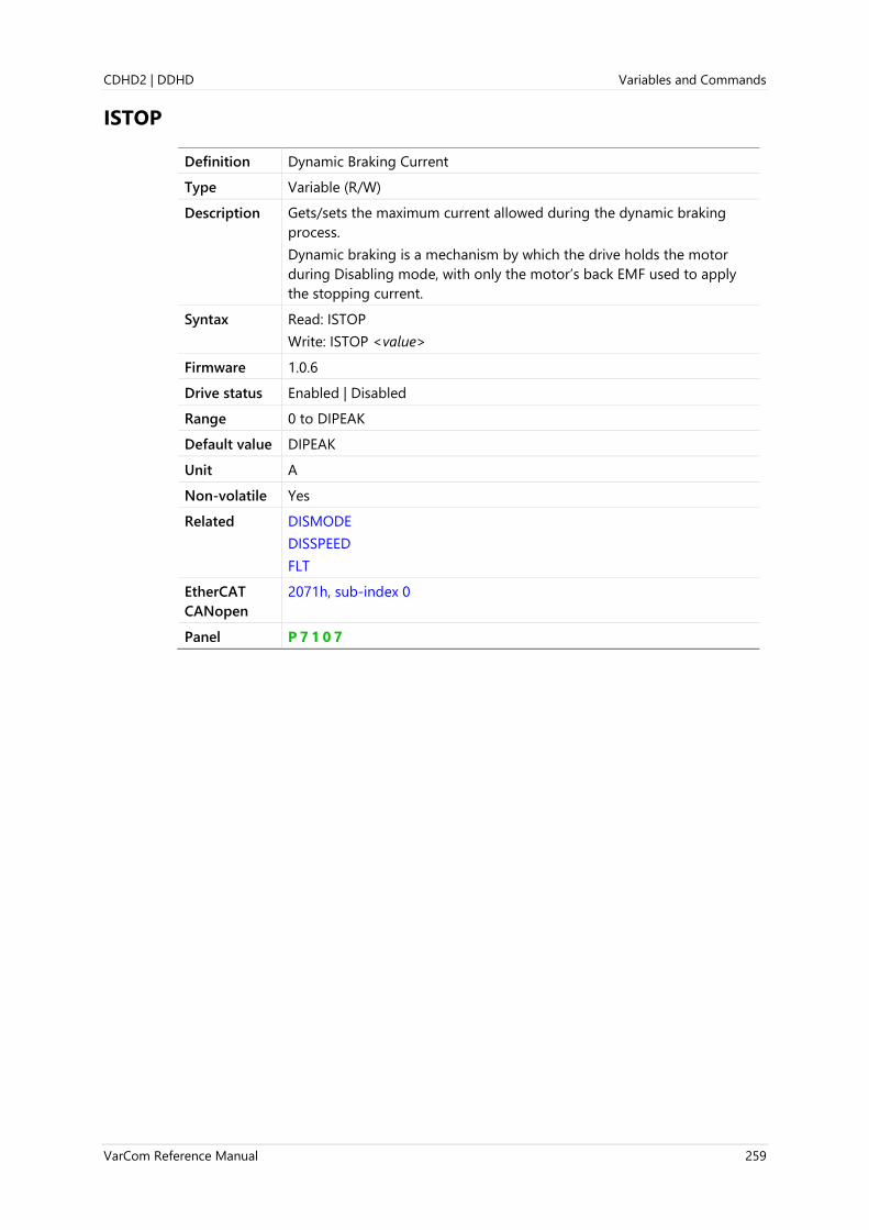
CDHD2 | DDHD Variables and Commands
VarCom Reference Manual 259
ISTOP
Definition Dynamic Braking Current
Type Variable (R/W)
Description Gets/sets the maximum current allowed during the dynamic braking
process.
Dynamic braking is a mechanism by which the drive holds the motor
during Disabling mode, with only the motor’s back EMF used to apply
the stopping current.
Syntax Read: ISTOP
Write: ISTOP <value>
Firmware 1.0.6
Drive status Enabled | Disabled
Range 0 to DIPEAK
Default value DIPEAK
Unit A
Non-volatile Yes
Related DISMODE
DISSPEED
FLT
EtherCAT
CANopen
2071h, sub-index 0
Panel P 7 1 0 7

Variables and Commands CDHD2 | DDHD
260 VarCom Reference Manual
IU
Definition Phase U Actual Current
Type Variable (R)
Description Indicates the actual current in Phase U (of UVW).
Syntax IU
Firmware 1.0.6
Drive status Enabled | Disabled
Range Not applicable
Default value Not applicable
Unit A
Non-volatile No
Related I
ID
ICMD
ILIM
IUOFFSET
IV
EtherCAT
CANopen
2072h, sub-index 0
Panel P 1 3 2 1

CDHD2 | DDHD Variables and Commands
VarCom Reference Manual 261
IUOFFSET
Definition Phase U Current Offset
Type Variable (R)
Description Indicates the current offset of phase U (of UVW)..
Syntax IUOFFSET
Firmware 1.0.6
Drive status Enabled | Disabled
Range Not applicable
Default value Not applicable
Unit A
Non-volatile No
Related IU
EtherCAT
CANopen
2073h, sub-index 0
Panel P 1 3 2 2

Variables and Commands CDHD2 | DDHD
262 VarCom Reference Manual
IV
Definition Phase V Actual Current
Type Variable (R)
Description Indicates the actual current in phase V (of UVW).
Syntax IV
Firmware 1.0.6
Drive status Enabled | Disabled
Range Not applicable
Default value Not applicable
Unit A
Non-volatile No
Related I
ID
ICMD
ILIM
IU
IUOFFSET
EtherCAT
CANopen
2074h, sub-index 0
Panel P 1 3 2 3

CDHD2 | DDHD Variables and Commands
VarCom Reference Manual 263
IVOFFSET
Definition Phase V Current Offset
Type Variable (R)
Description Indicates the current offset of phase V (of UVW).
Syntax IVOFSET
Firmware 1.0.6
Drive status Enabled | Disabled
Range Not applicable
Default value Not applicable
Unit A
Non-volatile Yes
Related IV
EtherCAT
CANopen
2075h, sub-index 0
Panel P 1 3 2 4

Variables and Commands CDHD2 | DDHD
264 VarCom Reference Manual
IZERO
Definition Zero Procedure Current
Type Variable (R/W)
Description Gets/sets the current for the ZERO procedure.
Syntax IZERO
Firmware 1.0.6
Drive status Enabled | Disabled
Range 0 to DIPEAK
Default value 0.100
Unit A
Non-volatile Yes
Related ILIM
MIPEAK
ZERO
EtherCAT
CANopen
2076h, sub-index 0
Panel P 7 0 0 6

CDHD2 | DDHD Variables and Commands
VarCom Reference Manual 265
J
Definition Jog Command
Type Command
Description Issues a velocity jog.
If the drive has been disabled, the jog command is reset to zero.
When issuing jog command from Terminal, OPMODE 0 is required.
When issuing jog command from operator panel, either OPMODE 0 or
OPMODE 8 can be in effect.
Syntax J Queries the command
J speed
Starts jog at a constant speed.
J speed duration
Starts jog at a constant speed for specified duration, after which a
zero velocity command is issued.
Firmware 1.0.6
Drive status Enabled
Range speed: ±VLIM
duration: +[unlimited]
Default value Not applicable
Unit speed:
If MOTORTYPE 0 (Rotary):
UNITSROTVEL 0 = rps
UNITSROTVEL 1 = rpm
UNITSROTVEL 2 = deg/s
If MOTORTYPE 2 (Linear):
UNITSLINVEL 1 = mm/s
duration: ms
Non-volatile Not applicable
Example -->k
-->opmode 0
-->en
-->j 200 1000
-->
Related ACC
OPMODE
STEP
STOP
EtherCAT
CANopen
Not applicable
Panel C 0 0 0 4

Variables and Commands CDHD2 | DDHD
266 VarCom Reference Manual
JOGSPD1
Definition Jog Speed 1 Triggered by Input
Type Variable (R/W)
Description Defines a speed for a JOG command triggered by a digital input.
The configured digital input functionality defines whether the motor
moves in a positive (INMODE 38) or negative (INMODE 39) direction.
ACC and DEC define the acceleration and deceleration values.
Note Only one of the digital inputs defined for the jog function should be
activated at a time.
If two or more digital inputs are defined for the jog function and
activated at the same time, the drive will not jog the motor.
Syntax Read: JOGSPD1
Write: JOGSPD1 <value>
Firmware 1.40.0
Drive status Enabled | Disabled
Range 0 to VLIM
Default value 100.000
Unit According to UNITSROTVEL
Non-volatile Yes
Related JOGSPD2
EtherCAT
CANopen
Not applicable
Panel P 4 0 3 9
Digital input
0
1
OPMODE
X
0
SPEED 0
JOGSPD1 ACC DEC
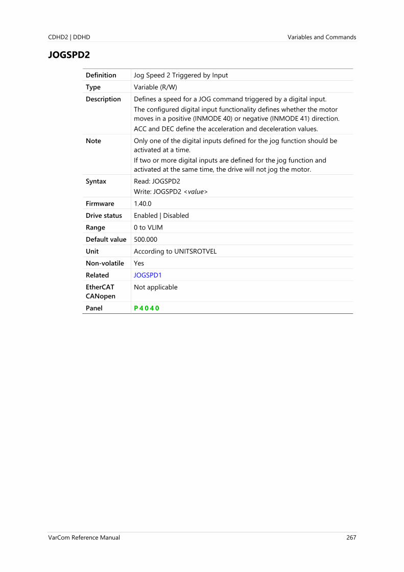
CDHD2 | DDHD Variables and Commands
VarCom Reference Manual 267
JOGSPD2
Definition Jog Speed 2 Triggered by Input
Type Variable (R/W)
Description Defines a speed for a JOG command triggered by a digital input.
The configured digital input functionality defines whether the motor
moves in a positive (INMODE 40) or negative (INMODE 41) direction.
ACC and DEC define the acceleration and deceleration values.
Note Only one of the digital inputs defined for the jog function should be
activated at a time.
If two or more digital inputs are defined for the jog function and
activated at the same time, the drive will not jog the motor.
Syntax Read: JOGSPD2
Write: JOGSPD2 <value>
Firmware 1.40.0
Drive status Enabled | Disabled
Range 0 to VLIM
Default value 500.000
Unit According to UNITSROTVEL
Non-volatile Yes
Related JOGSPD1
EtherCAT
CANopen
Not applicable
Panel P 4 0 4 0

Variables and Commands CDHD2 | DDHD
268 VarCom Reference Manual
K
Definition Disable Command
Type Command
Description Disables the drive. The behavior of the drive upon disable command is
defined by DISMODE.
K removes the software enable condition (SWEN) from the activation
chain.
Note Applicable in COMMODE 0 only.
When the drive is operating in COMMODE 1, it must be disabled
through the EtherCAT/CANopen interface.
Syntax K
Firmware 1.0.6
Drive status Enabled | Disabled
Range Not applicable
Default value Not applicable
Unit Not applicable
Non-volatile Not applicable
Related ACTIVE
EN
FLT
READY
REMOTE
ST
SWEN
EtherCAT
CANopen
Not applicable
Panel C 0 0 0 3 (toggle Enable/Disable)

CDHD2 | DDHD Variables and Commands
VarCom Reference Manual 269
KCBEMF
Definition Current BEMF Compensation Gain
Type Variable (R/W)
Description Gets/sets the feedforward BEMF compensation ratio for the current
control.
When the value of KCBEMF is changed, CONFIG is required.
Note As of version 1.40.0, the drive firmware includes a table that has
bundled parameter data for certain drive and motor pairings. When a
system drive and motor “parameter bundle” is found in the table, the
values of current loop parameters KCBEMF, KCD, KCFF, KCI, and KCP are
set automatically and cannot be manipulated by users.
Syntax Read: KCBEMF
Write: KCBEMF <value>
Firmware 1.0.6
Drive status Disabled
Range 0 to 2
Default value 1.000
Unit Not applicable
Non-volatile Yes
Related IFFLPFHZ
MKT
EtherCAT
CANopen
2003h, sub-index 0
Panel P 1 3 0 4

Variables and Commands CDHD2 | DDHD
270 VarCom Reference Manual
KCD
Definition Dead Time Compensation Minimal Level
Type Variable (R/W)
Description Minimum current level to start compensation for dead-time effect.
When the value of KCD is changed, CONFIG is required.
Note As of version 1.40.0, the drive firmware includes a table that has
bundled parameter data for certain drive and motor pairings. When a
system drive and motor “parameter bundle” is found in the table, the
values of current loop parameters KCBEMF, KCD, KCFF, KCI, and KCP are
set automatically and cannot be manipulated by users.
Syntax Read: KCD
Write: KCD <value>
Firmware 1.3.2
Drive status Disabled
Range 0 to 10
Default value 2.00
Unit Not applicable
Non-volatile Yes
Related PWMFRQ
EtherCAT
CANopen
20EFh, sub-index 0
Panel P 1 3 0 2

CDHD2 | DDHD Variables and Commands
VarCom Reference Manual 271
KCFF
Definition Current KFF Gain
Type Variable (R/W)
Description Gets/sets the current controller feedforward (KFF) gain.
When the value of KCFF is changed, CONFIG is required.
Note As of version 1.40.0, the drive firmware includes a table that has
bundled parameter data for certain drive and motor pairings. When a
system drive and motor “parameter bundle” is found in the table, the
values of current loop parameters KCBEMF, KCD, KCFF, KCI, and KCP are
set automatically and cannot be manipulated by users.
Syntax Read: KCFF
Write: KCFF <value>
Firmware 1.0.6
Drive status Disabled
Range 0 to 100
Default value 1.000
Unit Not applicable
Non-volatile Yes
Related KCBEMF
KCI
KCP
EtherCAT
CANopen
2082h, sub-index 0
Panel P 1 3 0 3

Variables and Commands CDHD2 | DDHD
272 VarCom Reference Manual
KCI
Definition Current KI Gain
Type Variable (R/W)
Description Gets/sets the current controller integrator (KI) gain.
When the value of KCI is changed, CONFIG is required.
Note As of version 1.40.0, the drive firmware includes a table that has
parameter bundled data for certain drive and motor pairings. When a
system drive and motor “parameter bundle” is found in the table, the
values of current loop parameters KCBEMF, KCD, KCFF, KCI, and KCP are
set automatically and cannot be manipulated by users.
Syntax Read: KCI
Write: KCI <value>
Firmware 1.0.6
Drive status Disabled
Range 0 to 100
Default value 1.000
Unit Not applicable
Non-volatile Yes
Related KCBEMF
KCFF
KCP
EtherCAT
CANopen
2006h, sub-index 0
Panel P 1 3 0 1

CDHD2 | DDHD Variables and Commands
VarCom Reference Manual 273
KCMODE
Definition Current Loop Compatibility Mode
Type Variable (R/W)
Description Gets/sets the type of current control loop.
Enables use of the new firmware version while maintaining the existing
current control settings. Useful for applications in which the upgrade to
the latest current control structure is not desired.
Syntax Read: KCMODE
Write: KCMODE <value>
Firmware 1.3.2
Drive status Disabled
Range 0 = Current control loop for firmware version 1.3.2 and higher.
1 = Keeps the current control loop from a previous firmware version
(SSV file).
After changing KCMODE from 0 to 1, you must issue the command
SAVE, and recycle the drive’s AC power.
2 = Uses the latest version of the current controller; recommended
except in specific cases of backward compatibility issues.
3 = Reserved.
4 = Reserved.
5 = Reserved.
6= Enhanced current control loop. Provides better current symmetry
and better bandwidth.
Note KCMODE 6 is the default value.
Users of previous firmware versions may want to change or keep
KCMODE at its previous setting to maintain backward compatible and
avoid fine tuning. However, for new applications the Enhanced Current
Loop setting is highly recommended to achieve better performance and
bandwidth.
Default value 6
Unit Not applicable
Non-volatile Yes
Related CONFIG
ML
EtherCAT
CANopen
2106h, sub-index 0
Panel P 1 3 0 5
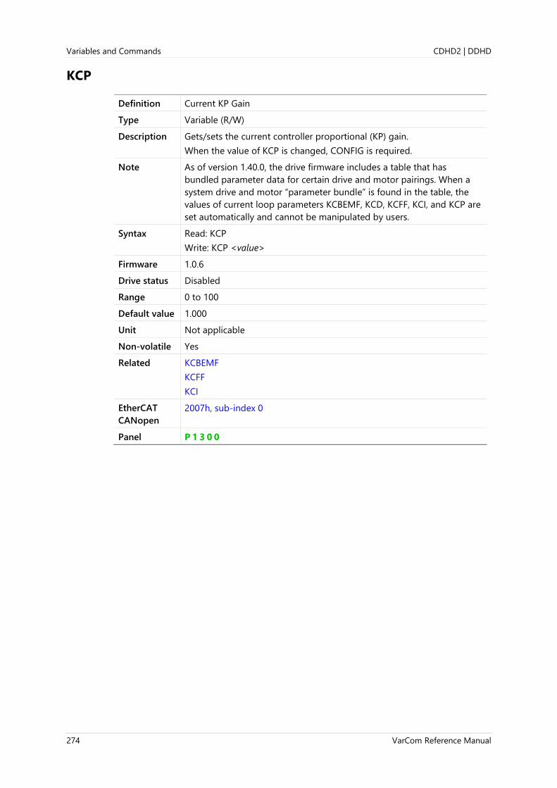
Variables and Commands CDHD2 | DDHD
274 VarCom Reference Manual
KCP
Definition Current KP Gain
Type Variable (R/W)
Description Gets/sets the current controller proportional (KP) gain.
When the value of KCP is changed, CONFIG is required.
Note As of version 1.40.0, the drive firmware includes a table that has
bundled parameter data for certain drive and motor pairings. When a
system drive and motor “parameter bundle” is found in the table, the
values of current loop parameters KCBEMF, KCD, KCFF, KCI, and KCP are
set automatically and cannot be manipulated by users.
Syntax Read: KCP
Write: KCP <value>
Firmware 1.0.6
Drive status Disabled
Range 0 to 100
Default value 1.000
Unit Not applicable
Non-volatile Yes
Related KCBEMF
KCFF
KCI
EtherCAT
CANopen
2007h, sub-index 0
Panel P 1 3 0 0

CDHD2 | DDHD Variables and Commands
VarCom Reference Manual 275
KCUSERGAIN
Definition Current User Gain
Type Variable (R/W)
Description Gets/sets the current user gain.
Syntax Read: KCUSERGAIN
Write: KCUSERGAIN <value>
Firmware 1.41.x
Drive status Enabled | Disabled
Range 0.1 to 10
Default value 1.000
Unit Not applicable
Non-volatile Yes
Related
EtherCAT
CANopen
Not applicable

Variables and Commands CDHD2 | DDHD
276 VarCom Reference Manual
KNLAFRC
Definition HD Acceleration Feedforward
Type Variable (R/W)
Description ICMD acceleration feedforward.
Syntax Read: KNLAFRC
Write: KNLAFRC <value>
Firmware 1.15.xx
Drive status Enabled | Disabled
Range 0 to 200
Default value 0
Unit %
Non-volatile Yes
Related KNLD
KNLI
KNLIV
KNLP
EtherCAT
CANopen
Not applicable
Panel P 1 0 0 7

CDHD2 | DDHD Variables and Commands
VarCom Reference Manual 277
KNLD
Definition HD Derivative Gain
Type Variable (R/W)
Description KNLD is the HD control equivalent of PID D. It is used in the HD control
loop to reduce velocity error.
The feedback gain parameters are tuned in the following general order:
KNLD → KNLIV → KNLP → KNLI
Syntax Read: KNLD
Write: KNLD <value>
Firmware 1.0.6
Drive status Enabled | Disabled
Range 0 to 2000
Default value 80.000
Unit Hz
Non-volatile Yes
Related KNLI
KNLP
KNLIV
POSCONTROLMODE
EtherCAT
CANopen
2017h, sub-index 0
Panel P 1 0 0 3

Variables and Commands CDHD2 | DDHD
278 VarCom Reference Manual
KNLDSOURCEMODE
Definition KNLD Source Mode
Type Variable (R/W)
Description Defines the source of the KNLD derivative gain for the nonlinear
controller KNLD block.
If the drive system detects an electronic motor nameplate (MTP), the
drive automatically sets KNLDSOURCE=2, and the user cannot
manipulate the value.
If an electronic motor nameplate is not in use (MTPMODE=0), the user
can define the KNLD source.
When the value of KNLDSOURCEMODE is changed, CONFIG is required.
Syntax Read: KNLDSOURCEMODE
Write: KNLDSOURCEMODE<value>
Firmware 2.0.x
Drive status Enabled | Disabled
Range 0 = Direct derivative
1 = Speed observer
2 = sensAR speed; applicable only for sensAR feedback
Default value 0
Unit Not applicable
Non-volatile Yes
Related KNLD
MTPMODE
EtherCAT
CANopen
Not applicable

CDHD2 | DDHD Variables and Commands
VarCom Reference Manual 279
KNLDUALLOOPAFF
Definition Dual Loop Acceleration Feedforward
Type Variable (R/W)
Description The acceleration feedforward for the dual-feedback position control
loop.
Syntax Read: KNLDUALLOOPAFF
Write: KNLDUALLOOPAFF <value>
Firmware 2.0.x
Drive status Enabled | Disabled
Range 0 to 200
Default value 0
Unit %
Non-volatile Yes
Related KNLDUALLOOPKP
KNLDUALLOOPVFF
EtherCAT
CANopen
Not applicable

Variables and Commands CDHD2 | DDHD
280 VarCom Reference Manual
KNLDUALLOOPKP
Definition Dual Loop Proportional Gain
Type Variable (R/W)
Description The proportional gain for the dual-feedback position control loop.
If the application does not require steady state tracking, it is
recommended to set KNLDUALLOOPVFF=0.
If the application has high friction, it recommended to use a higher
value for KNLDUALLOOPKP and a lower value for KNLDUALLOOPVFF.
Syntax Read: KNLDUALLOOPKP
Write: KNLDUALLOOPKP <value>
Firmware 2.0.x
Drive status Enabled | Disabled
Range 0 to 2000
Default value 0
Unit Hz
Non-volatile Yes
Related KNLDUALLOOPAFF
KNLDUALLOOPVFF
EtherCAT
CANopen
Not applicable

CDHD2 | DDHD Variables and Commands
VarCom Reference Manual 281
KNLDUALLOOPVFF
Definition Dual Loop Velocity Feedforward
Type Variable (R/W)
Description The velocity feedforward for the dual-feedback position control loop.
When KNLDUALLOOPVFF=1, the steady state position error (PE) will be
near 0:
When KNLDUALLOOPVFF<1, the steady state position error (PE) will be
proportional to velocity (V):
Reducing KNLDUALLOOPVFF also has a smoothing effect on the
command.
Syntax Read: KNLDUALLOOPVFF
Write: KNLDUALLOOVFF <value>
Firmware 2.0.x
Drive status Enabled | Disabled
Range 0 to 2
Default value 0
Unit Not applicable
Non-volatile Yes
Related KNLDUALLOOPAFF
KNLDUALLOOPKP
EtherCAT
CANopen
Not applicable

Variables and Commands CDHD2 | DDHD
282 VarCom Reference Manual
KNLI
Definition HD Integral Gain
Type Variable (R/W)
Description KNLIV is the HD control equivalent of PID I.
It is used in the HD control loop to reduce standstill error.
The feedback gain parameters are tuned in the following general order:
KNLD → KNLIV → KNLP → KNLI
Syntax Read: KNLI
Write: KNLI <value>
Firmware 1.0.6
Drive status Enabled | Disabled
Range 0 to 200
Default value 10.000
Unit Hz
Non-volatile Yes
Related KNLD
KNLP
KNLIV
POSCONTROLMODE
EtherCAT
CANopen
2018h, sub-index 0
Panel P 1 0 0 6
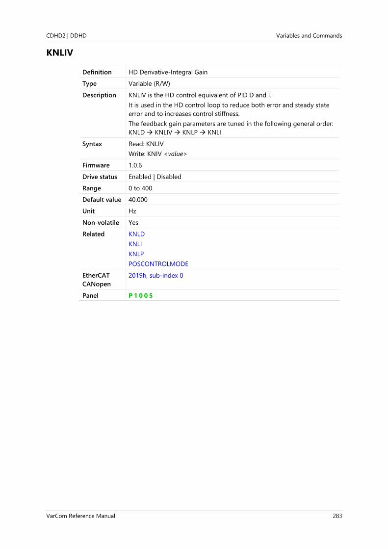
CDHD2 | DDHD Variables and Commands
VarCom Reference Manual 283
KNLIV
Definition HD Derivative-Integral Gain
Type Variable (R/W)
Description KNLIV is the HD control equivalent of PID D and I.
It is used in the HD control loop to reduce both error and steady state
error and to increases control stiffness.
The feedback gain parameters are tuned in the following general order:
KNLD → KNLIV → KNLP → KNLI
Syntax Read: KNLIV
Write: KNIV <value>
Firmware 1.0.6
Drive status Enabled | Disabled
Range 0 to 400
Default value 40.000
Unit Hz
Non-volatile Yes
Related KNLD
KNLI
KNLP
POSCONTROLMODE
EtherCAT
CANopen
2019h, sub-index 0
Panel P 1 0 0 5

Variables and Commands CDHD2 | DDHD
284 VarCom Reference Manual
KNLP
Definition HD Proportional Gain
Type Variable (R/W)
Description KNLP is the HD control equivalent of PID P.
It is used in the HD control loop to reduce position error.
The feedback gain parameters are tuned in the following general order:
KNLD → KNLIV → KNLP → KNLI
Syntax Read: KNLP
Write: KNLP <value>
Firmware 1.0.6
Drive status Enabled | Disabled
Range 0 to 400
Default value 30.000
Unit Hz
Non-volatile Yes
Related KNLD
KNLI
KNLIV
POSCONTROLMODE
EtherCAT
CANopen
201Ah, sub-index 0
Panel P 1 0 0 4

CDHD2 | DDHD Variables and Commands
VarCom Reference Manual 285
KNLUSERGAIN
Definition HD Global Gain
Type Variable (R/W)
Description HD adaptive gain scaling factor
Syntax Read: KNLUSERGAIN
Write: KNLUSERGAIN <value>
Firmware 1.0.6
Drive status Enabled | Disabled
Range 0.1 to 3.0
Default value 0.500
Unit Not applicable
Non-volatile Yes
Related KNLI
KNLP
POSCONTROLMODE
EtherCAT
CANopen
201Bh, sub-index 0
Panel P 1 0 0 2

Variables and Commands CDHD2 | DDHD
286 VarCom Reference Manual
KNLVFF
Definition HD Velocity Feedforward
Type Variable (R/W)
HD velocity feedforward
Description HD velocity feedforward. The default value of 1 represents 100%
feedforward value, which ensures the highest HD loop responsiveness.
In applications that require a “softer” response, KNLVFF should be
rapidly reduced until the desired response is achieved.
Syntax Read: KNLVFF
Write: KNLVFF <value>
Firmware 1.20.6
Drive status Enabled | Disabled
Range 0.000 to 1.000
Default value 1.000
Unit Not applicable
Non-volatile Yes
Related
EtherCAT
CANopen
Not applicable
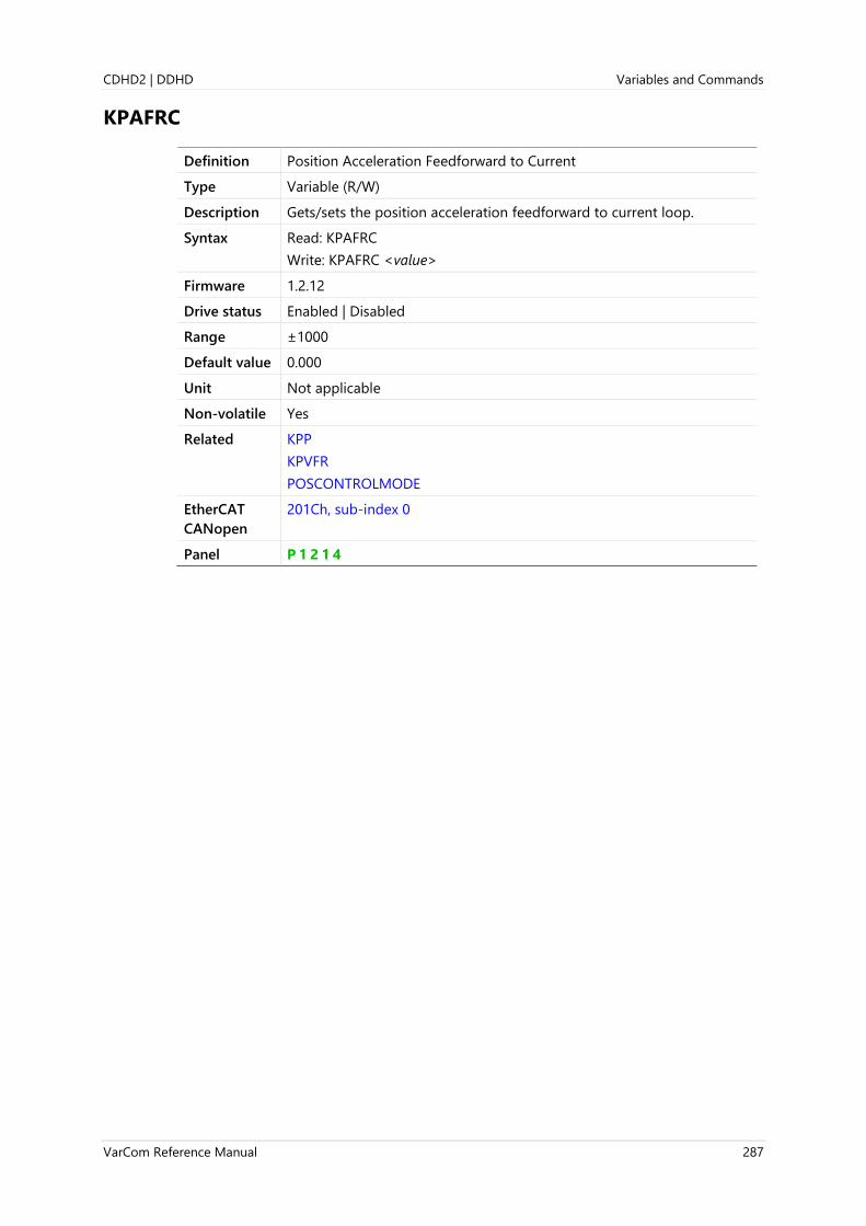
CDHD2 | DDHD Variables and Commands
VarCom Reference Manual 287
KPAFRC
Definition Position Acceleration Feedforward to Current
Type Variable (R/W)
Description Gets/sets the position acceleration feedforward to current loop.
Syntax Read: KPAFRC
Write: KPAFRC <value>
Firmware 1.2.12
Drive status Enabled | Disabled
Range ±1000
Default value 0.000
Unit Not applicable
Non-volatile Yes
Related KPP
KPVFR
POSCONTROLMODE
EtherCAT
CANopen
201Ch, sub-index 0
Panel P 1 2 1 4
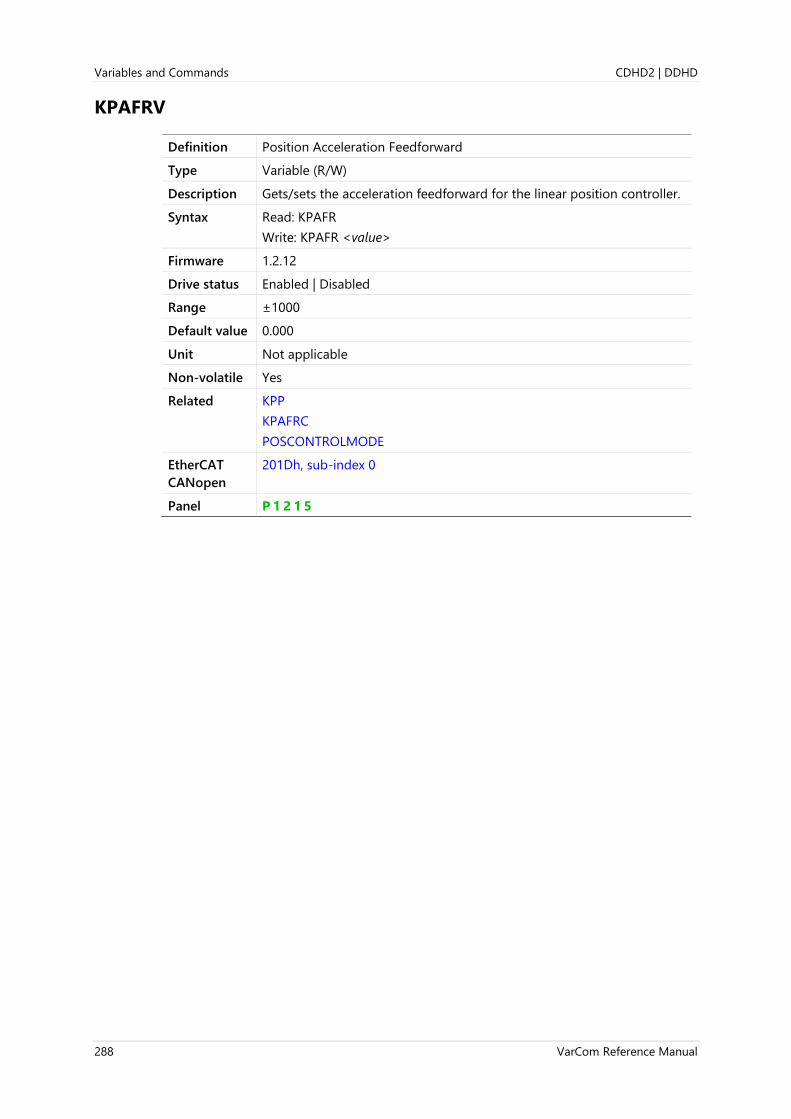
Variables and Commands CDHD2 | DDHD
288 VarCom Reference Manual
KPAFRV
Definition Position Acceleration Feedforward
Type Variable (R/W)
Description Gets/sets the acceleration feedforward for the linear position controller.
Syntax Read: KPAFR
Write: KPAFR <value>
Firmware 1.2.12
Drive status Enabled | Disabled
Range ±1000
Default value 0.000
Unit Not applicable
Non-volatile Yes
Related KPP
KPAFRC
POSCONTROLMODE
EtherCAT
CANopen
201Dh, sub-index 0
Panel P 1 2 1 5
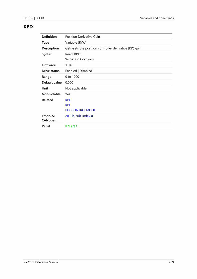
CDHD2 | DDHD Variables and Commands
VarCom Reference Manual 289
KPD
Definition Position Derivative Gain
Type Variable (R/W)
Description Gets/sets the position controller derivative (KD) gain.
Syntax Read: KPD
Write: KPD <value>
Firmware 1.0.6
Drive status Enabled | Disabled
Range 0 to 1000
Default value 0.000
Unit Not applicable
Non-volatile Yes
Related KPE
KPI
POSCONTROLMODE
EtherCAT
CANopen
201Eh, sub-index 0
Panel P 1 2 1 1

Variables and Commands CDHD2 | DDHD
290 VarCom Reference Manual
KPE
Definition Position Proportional Adaptive Gain
Type Variable (R/W)
Description The position proportional adaptive gain.
Syntax Read: KPE
Write: KPE <value>
Firmware 1.0.6
Drive status Enabled | Disabled
Range 0 to 4
Default value 0.000
Unit Not applicable
Non-volatile Yes
Related KPD
KPI
POSCONTROLMODE
EtherCAT
CANopen
201Fh, sub-index 0
Panel P 1 2 1 2

CDHD2 | DDHD Variables and Commands
VarCom Reference Manual 291
KPI
Definition Position Integral Gain
Type Variable (R/W)
Description Gets/sets the position controller integral (KI) gain.
Syntax Read: KPI
Write: KPI <value>
Firmware 1.0.6
Drive status Enabled | Disabled
Range 0 to 1000
Default value 0.000
Unit Hz
Non-volatile Yes
Related KPE
KPD
POSCONTROLMODE
EtherCAT
CANopen
2020h, sub-index 0
Panel P 1 2 0 8

Variables and Commands CDHD2 | DDHD
292 VarCom Reference Manual
KPISATIN
Definition Position Integral Input Saturation
Type Variable (R/W)
Description The position integral input saturation.
Syntax Read: KPISATIN
Write: KPISATIN <value>
Firmware 1.0.6
Drive status Enabled | Disabled
Range 0 to 10000
Default value 0.000
Unit If MOTORTYPE 0 (Rotary): rev
If MOTORTYPE 2 (Linear): mm
Non-volatile Yes
Related KPI
KPISATOUT
POSCONTROLMODE
EtherCAT
CANopen
2077h, sub-index 0
Panel P 1 2 0 9

CDHD2 | DDHD Variables and Commands
VarCom Reference Manual 293
KPISATOUT
Definition Position Integral Output Saturation
Type Variable (R/W)
Description The position integral output saturation.
Syntax Read: KPISATOUT
Write: KPISATOUT <value>
Firmware 1.0.6
Drive status Enabled | Disabled
Range 0 to 10000
Default value 0.000
Unit rps
Non-volatile Yes
Related KPI
KPISATIN
POSCONTROLMODE
EtherCAT
CANopen
2021h, sub-index 0
Panel P 1 2 1 0

Variables and Commands CDHD2 | DDHD
294 VarCom Reference Manual
KPP
Definition Position Proportional Gain
Type Variable (R/W)
Description Gets/sets the proportional gain for the linear position controller
(POSCONTROLMODE 0).
The proportional gain for the linear position controller is doubled
during motion when KPPCHANGEMODE is 1.
Syntax Read: KPP
Write: KPP <value>
Firmware 1.0.6
Drive status Enabled | Disabled
Range 0 to 1200
Default value 1.000
Unit Rotary: rps/rev
Linear: (mm/sec)/mm
Non-volatile Yes
Related KPD
KPE
KPI
KPVFR
POSCONTROLMODE
EtherCAT
CANopen
2022h, sub-index 0
Panel P 1 2 0 7

CDHD2 | DDHD Variables and Commands
VarCom Reference Manual 295
KPPCHANGEMODE
Definition KPP Change Mode
Type Variable (R/W)
Description This parameter defines the behavior of the linear position controller
proportional gain (KPP). When KPPCHANGEMODE=1, the linear position
controller proportional gain is doubled during motion.
Syntax Read: KPPCHANGEMODE
Write: KPPCHANGEMODE <value>
Firmware 2.0.x
Drive status Disabled
Range 0 = Normal behavior of the linear position controller proportional gain
(KPP).
1 = The linear position controller proportional gain is doubled during
motion.
Default value 0
Unit Not applicable
Non-volatile Yes
Related KPP
EtherCAT
CANopen
218Fh, sub-index 0

Variables and Commands CDHD2 | DDHD
296 VarCom Reference Manual
KPVFR
Definition Position Velocity Feedforward
Type Variable (R/W)
Description The position control velocity feedforward.
Syntax Read: KPVFR
Write: KPVFR <value>
Firmware 1.0.6
Drive status Enabled | Disabled
Range -2 to 2
Default value 0.00
Unit Not applicable
Non-volatile Yes
Related KPD
KPE
KPI
KPP
POSCONTROLMODE
EtherCAT
CANopen
2023h, sub-index 0
Panel P 1 2 1 3

CDHD2 | DDHD Variables and Commands
VarCom Reference Manual 297
KVFR
Definition Velocity Feedforward Ratio
Type Variable (R/W)
Description Gets/sets the velocity feedforward ratio.
By manipulating the proportional controller with a smaller error, KVFR
determines how responsive the system will be. The higher the value of
KVFR, the more responsive the system. For example, in a mechanical
system with high friction, KVFR less than 1 will provide better tracking at
steady state, and allow much higher integral gain without inducing
overshoot.
Syntax Read: KVFR
Write: KVFR <value>
Firmware 1.0.6
Drive status Enabled | Disabled
Range 0.000 to 1.000
Default value 0.000
Unit Not applicable
Non-volatile Yes
Related FILTMODE
KVP
KVI
VELCONTROLMODE
EtherCAT
CANopen
2025h, sub-index 0
Panel P 1 2 0 2

Variables and Commands CDHD2 | DDHD
298 VarCom Reference Manual
KVI
Definition Velocity Integral Gain
Type Variable (R/W)
Description Gets/sets the velocity integral gain.
KVI compensates for the steady state error. A higher value will cause
overshoot and oscillations.
Syntax Read: KVI
Write: KVI <value>
Firmware 1.0.6
Drive status Enabled | Disabled
Range 0 to 200000
Default value 0.000
Unit Hz
Non-volatile Yes
Related FILTMODE
KVFR
KVP
VELCONTROLMODE
EtherCAT
CANopen
2026h, sub-index 0
Panel P 1 2 0 1
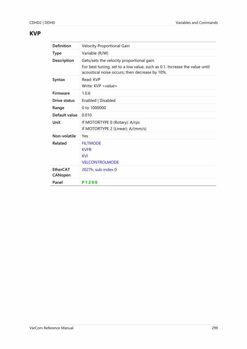
CDHD2 | DDHD Variables and Commands
VarCom Reference Manual 299
KVP
Definition Velocity Proportional Gain
Type Variable (R/W)
Description Gets/sets the velocity proportional gain.
For best tuning, set to a low value, such as 0.1. Increase the value until
acoustical noise occurs; then decrease by 10%.
Syntax Read: KVP
Write: KVP <value>
Firmware 1.0.6
Drive status Enabled | Disabled
Range 0 to 1000000
Default value 0.010
Unit If MOTORTYPE 0 (Rotary): A/rps
If MOTORTYPE 2 (Linear): A/(mm/s)
Non-volatile Yes
Related FILTMODE
KVFR
KVI
VELCONTROLMODE
EtherCAT
CANopen
2027h, sub-index 0
Panel P 1 2 0 0

Variables and Commands CDHD2 | DDHD
300 VarCom Reference Manual
LIMSWITCHNEG
Definition Limit Switch Negative Status
Type Variable (R)
Description LIMSWITCHNEG indicates the status of all negative limit events.
Its individual bits are set or cleared independently of each other, in
response to the events described below.
Possible values are combinations of bit 0, bit 1, and bits 2 and 3. It is
sufficient, however, to monitor bit 2 only, or bit 3 only to obtain the
limit switch status.
The bits have the following meanings.
Bit 0:
0 = ....
1 = The actual position (PFB) is less than the minimum position for the
software limit POSLIMNEG.
Bit 1:
0 = ....
1 = (xx1x) The input assigned negative limit switch functionality by
INMODE n 6 is activated.
Bit 2 and Bit 3 are always set or cleared together. These two bits will not
be set if bits 2 and 3 of LIMSWITCHPOS are already set.
0 = Bit 1 is cleared AND the actual position is greater than the
captured position.
1 = Bit 1 is set (negative limit switch is activated) AND the actual
position (PFB) is captured internally.
Syntax LIMSWITCHNEG
Firmware 1.2.12
Drive status Enabled | Disabled
Range Not applicable
Default value Not applicable
Unit Not applicable
Non-volatile No
Related HOMETYPE
INMODE
LIMSWITCHPOS
POSLIMMODE
EtherCAT
CANopen
2078h, sub-index 0
Panel P 5 0 0 0

CDHD2 | DDHD Variables and Commands
VarCom Reference Manual 301
LIMSWITCHPOS
Definition Limit Switch Positive Status
Type Variable (R)
Description LIMSWITCHPOS indicates the status of all positive limit events.
Its individual bits are set or cleared independently of each other, in
response to the events described below.
Possible values are combinations of bit 0, bit 1, and bits 2 and 3. It is
sufficient, however, to monitor bit 2 only, or bit 3 only to obtain the
limit switch status.
The bits have the following meanings.
Bit 0:
0 = ....
1 = The actual position (PFB) is greater than the maximum position for
software limit POSLIMPOS.
Bit 1:
0 =
1 = The input assigned negative limit switch functionality by INMODE
n 6 is activated.
Bit 2 and Bit 3 are always set or cleared together. These two bits will not
be set if bits 2 and 3 of LIMSWITCHNEG are already set.
0 = Bit 1 is cleared AND the actual position is less than the captured
position.
1 = Bit 1 is set (negative limit switch is activated) AND the actual
position (PFB) is captured internally.
Syntax LIMSWITCHPOS
Firmware 1.2.12
Drive status Enabled | Disabled
Range Not applicable
Default value Not applicable
Unit Not applicable
Non-volatile No
Related HOMETYPE
INMODE
LIMSWITCHNEG
POSLIMMODE
EtherCAT
CANopen
2079h, sub-index 0
Panel P 5 0 0 1

Variables and Commands CDHD2 | DDHD
302 VarCom Reference Manual
LINELOSSMODE
Definition Bus AC Supply Line Disconnect Mode
Type Variable (R/W)
Description Applicable only for DDHD and STO-certified CDHD2 drives (-ST
models).
A feature that monitors the bus supply, and defines how the drive will
respond if phase loss is detected.
Warning display: o
Warning message: Bus AC supply line disconnect
Fault display: o7
Fault message: Bus AC supply line disconnect
Syntax Read: LINELOSSMODE
Write: LINELOSSMODE <value>
Firmware 1.15.xx
Drive status Enable | Disable
Range 0 = Fault when drive enabled or disabled
1 = Fault when drive enabled, warning when disabled
2 = Warning when drive enabled or disabled
Default value 0
Unit Not applicable
Non-volatile Yes
Related LINELOSSRECOVER
LINELOSSTYPE
EtherCAT
CANopen
Not applicable
Panel P 7 3 0 6
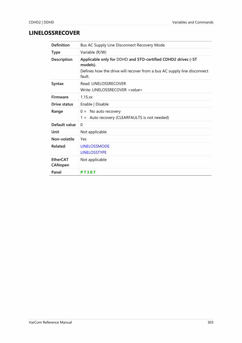
CDHD2 | DDHD Variables and Commands
VarCom Reference Manual 303
LINELOSSRECOVER
Definition Bus AC Supply Line Disconnect Recovery Mode
Type Variable (R/W)
Description Applicable only for DDHD and STO-certified CDHD2 drives (-ST
models).
Defines how the drive will recover from a bus AC supply line disconnect
fault.
Syntax Read: LINELOSSRECOVER
Write: LINELOSSRECOVER <value>
Firmware 1.15.xx
Drive status Enable | Disable
Range 0 = No auto recovery
1 = Auto recovery (CLEARFAULTS is not needed)
Default value 0
Unit Not applicable
Non-volatile Yes
Related LINELOSSMODE
LINELOSSTYPE
EtherCAT
CANopen
Not applicable
Panel P 7 3 0 7

Variables and Commands CDHD2 | DDHD
304 VarCom Reference Manual
LINELOSSTYPE
Definition Bus AC Supply Line Disconnect Type
Type Variable (R/W)
Description Applicable only for DDHD and STO-certified CDHD2 drives (-ST
models).
Defines the types of bus AC supply line disconnect fault. Programmable
only if supported by hardware.
Syntax Read: LINELOSSTYPE
Write: LINELOSSTYPE <value>
Firmware 1.15.xx
Drive status Enable | Disable
Range 0 – No detection
1 – Detection for one phase connection
2 – Detection for three phase connection
Default value 0
Unit Not applicable
Non-volatile Yes
Related LINELOSSMODE
LINELOSSRECOVER
EtherCAT
CANopen
Not applicable
Panel P 7 3 0 8

CDHD2 | DDHD Variables and Commands
VarCom Reference Manual 305
LIST
Definition List All Variables and Commands
Type Command
Description Returns a list of valid variables and commands. Only the variables
names, and not their values, are transmitted.
Note Some factory variables and commands, not intended for users, may
appear in the list.
Do not attempt to manipulate parameters that are not described in
the product documentation or Help.
Syntax LIST
Firmware 1.0.6
Drive status Enabled | Disabled
Range Not applicable
Default value Not applicable
Unit Not applicable
Non-volatile Not applicable
Related INFO
RECLIST
RECTRIGLIST
EtherCAT
CANopen
Not applicable

Variables and Commands CDHD2 | DDHD
306 VarCom Reference Manual
LMJR
Definition Load to Motor Inertia Ratio
Type Variable (R/W)
Description Gets/sets the ratio of the load inertia to the motor inertia.
If LMJR=2, for example, the total inertia is 3 times the inertia of the
motor:
Jtotal = MJ × (1+LMJR)
The motor rotor inertia (MJ) and the load moment of inertia ratio (LMJR)
define the total system moment of inertia.
LMJR can be set by the user or determined by an autotuning procedure.
Syntax Read: LMJR
Write: LMJR <value>
Firmware 1.0.6
Drive status Enabled | Disabled
Range 0 to 2000
Default value 1.000
Unit Not applicable
Non-volatile Yes
Related BW
LMJREST
LMJRESTST
MJ
TF
VELCONTROLMODE
EtherCAT
CANopen
207Ah, sub-index 0
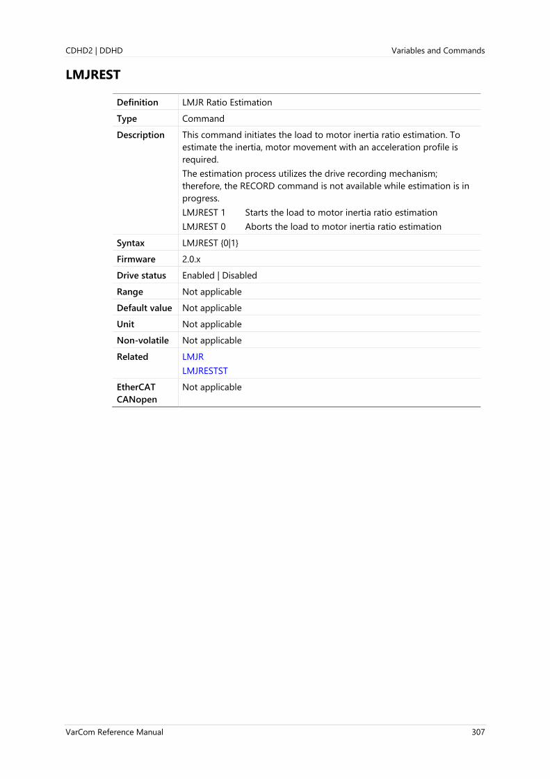
CDHD2 | DDHD Variables and Commands
VarCom Reference Manual 307
LMJREST
Definition LMJR Ratio Estimation
Type Command
Description This command initiates the load to motor inertia ratio estimation. To
estimate the inertia, motor movement with an acceleration profile is
required.
The estimation process utilizes the drive recording mechanism;
therefore, the RECORD command is not available while estimation is in
progress.
LMJREST 1 Starts the load to motor inertia ratio estimation
LMJREST 0 Aborts the load to motor inertia ratio estimation
Syntax LMJREST {0|1}
Firmware 2.0.x
Drive status Enabled | Disabled
Range Not applicable
Default value Not applicable
Unit Not applicable
Non-volatile Not applicable
Related LMJR
LMJRESTST
EtherCAT
CANopen
Not applicable

Variables and Commands CDHD2 | DDHD
308 VarCom Reference Manual
LMJRESTST
Definition LMRJ Ratio Estimation Status
Type Variable (R)
Description Indicates the status of the load to motor inertia ratio estimation
process.
Possible responses:
Waiting For Arm
Waiting for the LMJREST command to start estimation
Waiting For Motion
Waiting for the start of motor motion
Starting...
Starting the estimation.
Analyzing...
Analyzing the motion data.
Unknown fault
A drive fault occurred during estimation.
Insufficient speed change
The motor speed is too low to estimate inertia .
LMJR estimation aborted
Estimation canceled by user.
Syntax LMJRESTST
Firmware 2.0.x
Drive status Enabled | Disabled
Range
Default value Not applicable
Unit Not applicable
Non-volatile No
Related LMJR
LMJREST
EtherCAT
CANopen
Not applicable

CDHD2 | DDHD Variables and Commands
VarCom Reference Manual 309
LMUNITSDEN
Definition Motor to Load Scaling Denominator
Type Variable (R/W)
Description LMUNITSDEN and LMUNITSNUM define the mechanical ratio of the
motor feedback to the load feedback.
LMUNITSDEN gets/sets the denominator of this ratio.
Note Replaces SFBUNITSDEN
Syntax Read: LMUNITSDEN
Write: LMUNITSDEN <value>
Firmware 2.0.x
Drive status Disabled
Range 1 to 2147483647
Default value 1
Unit Not applicable
Non-volatile Yes
Related SFB
LMUNITSNUM
EtherCAT
CANopen
213Eh, sub-index 0
Panel P 2 1 1 4

Variables and Commands CDHD2 | DDHD
310 VarCom Reference Manual
LMUNITSNUM
Definition Motor to Load Scaling Numerator
Type Variable (R/W)
Description LMUNITSDEN and LMUNITSNUM define the mechanical ratio of the
motor feedback to the load feedback.
LMUNITSNUM gets/sets the numerator of this ratio.
Note Replaces SFBUNITSNUM
Syntax Read: LMUNITSNUM
Write: LMUNITSNUM <value>
Firmware 2.0.x
Drive status Disabled
Range -2147483647 to 2147483647
Default value 1
Unit Not applicable
Non-volatile Yes
Related SFB
LMUNITSDEN
EtherCAT
CANopen
213Dh, sub-index 0
Panel P 2 1 1 5

CDHD2 | DDHD Variables and Commands
VarCom Reference Manual 311
LOAD
Definition Load Parameters to RAM
Type Command
Description Loads configuration variables from non-volatile memory to RAM. Any
changes in configuration parameters which have been made since the
last SAVE will be overwritten by the values loaded from the non-volatile
memory.
Syntax LOAD
Firmware 1.0.6
Drive status Disabled
Range Not applicable
Default value Not applicable
Unit Not applicable
Non-volatile Not applicable
Related DUMP
FACTORYRESTORE
SAVE
EtherCAT
CANopen
1011h, sub-index 1

Variables and Commands CDHD2 | DDHD
312 VarCom Reference Manual
MACC
Definition Motor Acceleration
Type Variable (R/W)
Description Gets/sets the acceleration value according to the feedback device on the
motor.
MACC mirrors the value of ACC in order to maintain the correct value of
motor feedback or load feedback if SFBMODE changes.
If SFBMODE=0 (single loop control), the value of ACC is automatically
written to MACC; conversely, the value of MACC is automatically written
to ACC. It is therefore sufficient to write values to ACC. MACC will be
updated accordingly.
Syntax Read: MACC
Write: MACC <value>
Firmware 2.0.x
Drive status Enabled | Disabled
Range If MOTORTYPE 0 (Rotary):
UNITSROTACC 0 = 0.004 to 16666.666
UNITSROTACC 1 = 0.23 to 1000000
UNITSROTACC 2 = 1.35 to 6000000
If MOTORTYPE 2 (Linear):
UNITSLINACC 1 = 0.12 to 533333.333
Default value If MOTORTYPE 0 (Rotary):
UNITSROTACC 0 = 10.000
UNITSROTACC 1 = 40000.000
UNITSROTACC 2 = 3600.000
UNITSROTACC 3 = 50.000
If MOTORTYPE 2 (Linear):
UNITSLINACC 1 = 320.000
Unit If MOTORTYPE 0 (Rotary):
UNITSROTACC 0 = rps/s
UNITSROTACC 1 = rpm/s
UNITSROTACC 2 = deg/s2
If MOTORTYPE 2 (Linear):
UNITSLINACC 1 = mm/s2
Non-volatile Yes
Related ACC
SFBACC
SFBMODE
EtherCAT
CANopen
21A8h, sub-index 0
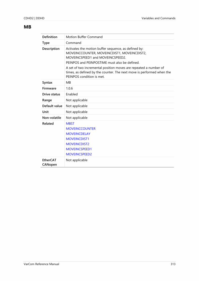
CDHD2 | DDHD Variables and Commands
VarCom Reference Manual 313
MB
Definition Motion Buffer Command
Type Command
Description Activates the motion buffer sequence, as defined by:
MOVEINCCOUNTER, MOVEINCDIST1, MOVEINCDIST2,
MOVEINCSPEED1 and MOVEINCSPEED2.
PEINPOS and PEINPOSTIME must also be defined.
A set of two incremental position moves are repeated a number of
times, as defined by the counter. The next move is performed when the
PEINPOS condition is met.
Syntax MB
Firmware 1.0.6
Drive status Enabled
Range Not applicable
Default value Not applicable
Unit Not applicable
Non-volatile Not applicable
Related MBST
MOVEINCCOUNTER
MOVEINCDELAY
MOVEINCDIST1
MOVEINCDIST2
MOVEINCSPEED1
MOVEINCSPEED2
EtherCAT
CANopen
Not applicable

Variables and Commands CDHD2 | DDHD
314 VarCom Reference Manual
MBST
Definition Motion Buffer Execution Status
Type Variable (R)
Description Returns the motion buffer repetition count during operation, and
returns the total duration as soon as the motion sequence is completed.
Syntax MBST
Firmware 1.0.6
Drive status Enabled | Disabled
Range Not applicable; see Example below
Default value Not applicable; see Example below
Unit Not applicable; see Example below
Non-volatile No
Example Running the following command sequence produces the following
MBST response.
-->MOVEINCCOUNTER=5
-->MOVEINCDIST1=2
-->MOVEINCDIST2=-2
-->MOVEINCSPEED1=200
-->MOVEINCSPEED2=300
-->MB
-->MBST
Running. Iteration: 1/5 Execution Time: 8ms
-->MBST
Running. Iteration: 1/5 Execution Time: 1020ms
-->MBST
Running. Iteration: 2/5 Execution Time: 2033ms
-->MBST
Running. Iteration: 3/5 Execution Time: 3044ms
-->MBST
Running. Iteration: 4/5 Execution Time: 4056ms
-->MBST
Running. Iteration: 5/5 Execution Time: 5068ms
-->MBST
Done. Execution Time: 5501ms
Related MB
MOVEINCCOUNTER
MOVEINCDIST1
MOVEINCDIST2
MOVEINCSPEED1
MOVEINCSPEED2
EtherCAT
CANopen
Not applicable
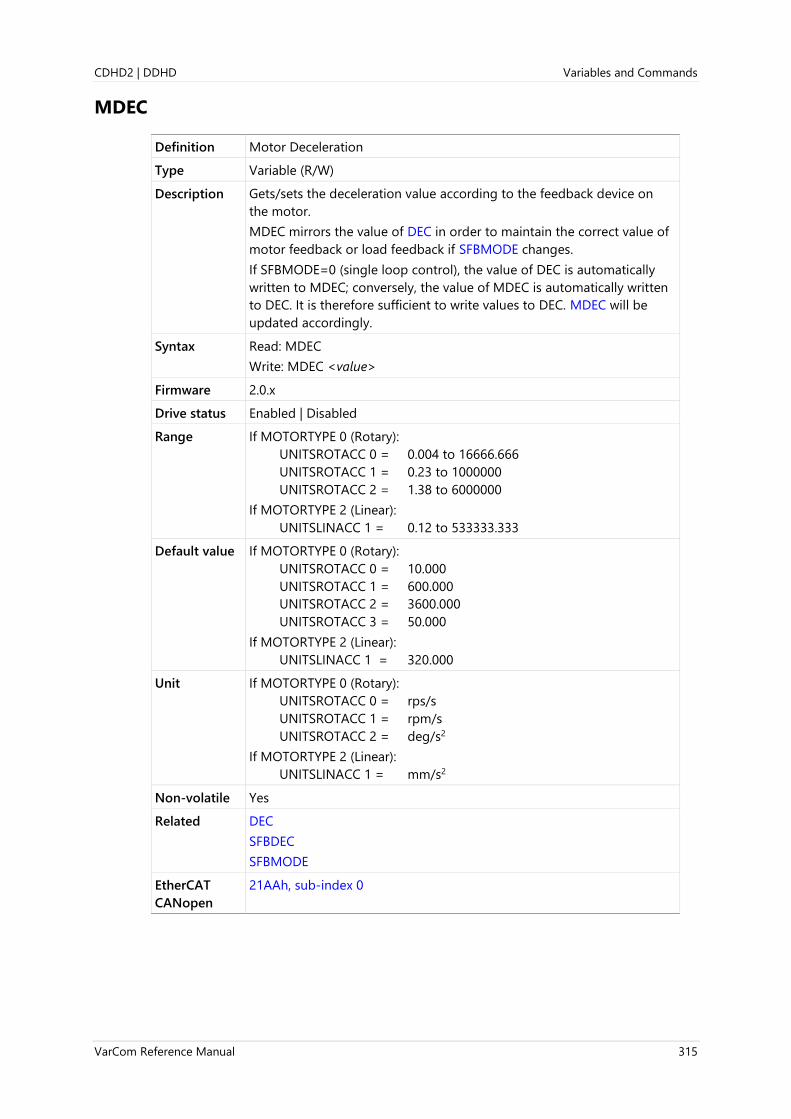
CDHD2 | DDHD Variables and Commands
VarCom Reference Manual 315
MDEC
Definition Motor Deceleration
Type Variable (R/W)
Description Gets/sets the deceleration value according to the feedback device on
the motor.
MDEC mirrors the value of DEC in order to maintain the correct value of
motor feedback or load feedback if SFBMODE changes.
If SFBMODE=0 (single loop control), the value of DEC is automatically
written to MDEC; conversely, the value of MDEC is automatically written
to DEC. It is therefore sufficient to write values to DEC. MDEC will be
updated accordingly.
Syntax Read: MDEC
Write: MDEC <value>
Firmware 2.0.x
Drive status Enabled | Disabled
Range If MOTORTYPE 0 (Rotary):
UNITSROTACC 0 = 0.004 to 16666.666
UNITSROTACC 1 = 0.23 to 1000000
UNITSROTACC 2 = 1.38 to 6000000
If MOTORTYPE 2 (Linear):
UNITSLINACC 1 = 0.12 to 533333.333
Default value If MOTORTYPE 0 (Rotary):
UNITSROTACC 0 = 10.000
UNITSROTACC 1 = 600.000
UNITSROTACC 2 = 3600.000
UNITSROTACC 3 = 50.000
If MOTORTYPE 2 (Linear):
UNITSLINACC 1 = 320.000
Unit If MOTORTYPE 0 (Rotary):
UNITSROTACC 0 = rps/s
UNITSROTACC 1 = rpm/s
UNITSROTACC 2 = deg/s2
If MOTORTYPE 2 (Linear):
UNITSLINACC 1 = mm/s2
Non-volatile Yes
Related DEC
SFBDEC
SFBMODE
EtherCAT
CANopen
21AAh, sub-index 0

Variables and Commands CDHD2 | DDHD
316 VarCom Reference Manual
MECHANGLE
Definition Motor Mechanical Angle
Type Variable (R)
Description The actual position of the motor within one revolution.
Syntax MECHANGLE
Firmware 1.0.6
Drive status Disabled
Range 0 to 65535
Default value Not applicable
Unit If MOTORTYPE 0 (Rotary): 65536/rev
If MOTORTYPE 2 (Linear): 65536/pitch
Non-volatile No
Related ELECTANGLE
FEEDBACKTYPE
MENCRES
MPHASE
EtherCAT
CANopen
2028h, sub-index 0
Panel P 2 0 2 3

CDHD2 | DDHD Variables and Commands
VarCom Reference Manual 317
MENCAQBFILT
Definition Motor Encoder AB Quadrature Filter
Type Variable (R/W)
Description Enables/disables the FPGA filter on A and B signals from incremental
encoders.
Disabling the filter prevents the drive from losing commutation without
sensing a fault.
Syntax Read: MENCAQBFILT
Write: MENCAQBFILT <value>
Firmware 1.4.4
Drive status Disable
Range 0 = Disables filter on incremental encoder A and B signals.
Recommended for use with high resolution incremental encoders, or
incremental encoders whose A and B phase difference is not 90°.
1 = Enables filter on incremental encoder A and B signals.
Default value 1
Unit Not applicable
Non-volatile Yes
Related AQBFILT
FEEDBACKTYPE
EtherCAT
CANopen
Not applicable
Panel P 2 0 2 4

Variables and Commands CDHD2 | DDHD
318 VarCom Reference Manual
MENCRES
Definition Motor Encoder Resolution
Type Variable (R/W)
Description For encoder feedback systems, gets/sets the resolution of the motor
encoder, in number of lines per revolution, or lines per pitch, of the
motor.
When the value of MENCRES is changed, CONFIG is required.
Syntax Read: MENCRES
Write: MENCRES <value>
Firmware 1.0.6
Drive status Disabled
Range Drive supporting rotary motor:
1 to 10,000 (LPR)
Drive supporting linear and rotary motors:
1 to 256,000,000 (LPR/LPP)
Default value 1048576 [LPR]
Note If the drive system detects an electronic motor nameplate (such as used
in the sensAR magnetic encoder), the value of parameter MENCRES is
loaded directly from the encoder memory to the drive RAM at power-
up.
Unit MOTORTYPE=0 (Rotary): lines per revolution (LPR)
MOTORTYPE=2 (Linear): lines per pitch (LPP)
Non-volatile Yes
Related FEEDBACKTYPE
MENCTYPE
EtherCAT
CANopen
608Fh, sub-index 1
Panel P 2 0 0 2
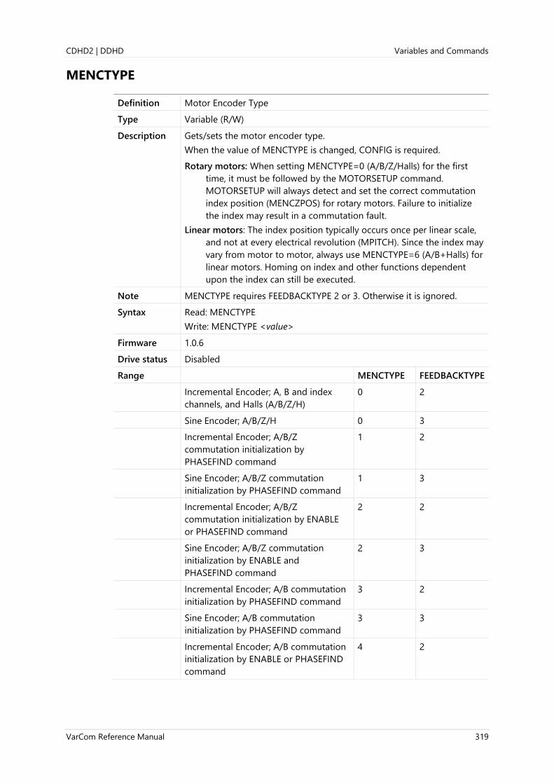
CDHD2 | DDHD Variables and Commands
VarCom Reference Manual 319
MENCTYPE
Definition Motor Encoder Type
Type Variable (R/W)
Description Gets/sets the motor encoder type.
When the value of MENCTYPE is changed, CONFIG is required.
Rotary motors: When setting MENCTYPE=0 (A/B/Z/Halls) for the first
time, it must be followed by the MOTORSETUP command.
MOTORSETUP will always detect and set the correct commutation
index position (MENCZPOS) for rotary motors. Failure to initialize
the index may result in a commutation fault.
Linear motors: The index position typically occurs once per linear scale,
and not at every electrical revolution (MPITCH). Since the index may
vary from motor to motor, always use MENCTYPE=6 (A/B+Halls) for
linear motors. Homing on index and other functions dependent
upon the index can still be executed.
Note MENCTYPE requires FEEDBACKTYPE 2 or 3. Otherwise it is ignored.
Syntax Read: MENCTYPE
Write: MENCTYPE <value>
Firmware 1.0.6
Drive status Disabled
Range MENCTYPE FEEDBACKTYPE
Incremental Encoder; A, B and index
channels, and Halls (A/B/Z/H)
0 2
Sine Encoder; A/B/Z/H 0 3
Incremental Encoder; A/B/Z
commutation initialization by
PHASEFIND command
1 2
Sine Encoder; A/B/Z commutation
initialization by PHASEFIND command
1 3
Incremental Encoder; A/B/Z
commutation initialization by ENABLE
or PHASEFIND command
2 2
Sine Encoder; A/B/Z commutation
initialization by ENABLE and
PHASEFIND command
2 3
Incremental Encoder; A/B commutation
initialization by PHASEFIND command
3 2
Sine Encoder; A/B commutation
initialization by PHASEFIND command
3 3
Incremental Encoder; A/B commutation
initialization by ENABLE or PHASEFIND
command
4 2

Variables and Commands CDHD2 | DDHD
320 VarCom Reference Manual
Sine Encoder; A/B ; commutation
initialization by ENABLE or PHASEFIND
command
4 3
Halls only 5 2
Incremental Encoder; A/B/H 6 2
Sine Encoder; A/B/H 6 3
EnDat 2.1 with Sine Signals 9 3
HIPERFACE with Sine Signals 10 3
Tamagawa Incremental Encoder
(8 wires)
11 2
Reserved 12 –
Sine Encoder; Analog Halls 14 3
Default value 6
Note If the drive system detects an electronic motor nameplate (such as used
in the sensAR magnetic encoder), the value of parameter MENCTYPE is
loaded directly from the encoder memory to the drive RAM at power-up.
Note MENCTYPE 14: Not supported by MOTORSETUP. Motor commissioning
must be performed manually. Requires FEEDBACKTYPE=3 (sine encoder)
and MPOLES=2.
Unit Not applicable
Non-volatile Yes
Related FEEDBACKTYPE
HALLS
PHASEFIND
EtherCAT
CANopen
2029h, sub-index 0
Panel P 2 0 0 1

CDHD2 | DDHD Variables and Commands
VarCom Reference Manual 321
MENCZPOS
Definition Motor Encoder Index Position
Type Variable (R/W)
Description For encoder feedback systems only, gets/sets the encoder index
position.
Syntax Read: MENCZPOS
Write: MENCZPOS <value>
Firmware 1.0.6
Drive status Disabled
Range 0 to 359
Default value 0
Unit Electrical degree
Non-volatile Yes
Related PHASEFIND
MENCTYPE
EtherCAT
CANopen
202Ah, sub-index 0
Panel P 2 0 2 5

Variables and Commands CDHD2 | DDHD
322 VarCom Reference Manual
MFB
Definition Motor Position Feedback
Type Variable (R)
Description Gets the position value of the feedback device on the motor, including
any offsets that have been added.
Syntax MFB
Firmware 2.0.x
Drive status Enabled | Disabled
Range ±(263 - 1)
Default value Not applicable
Unit Set by UNITSROTPOS and UNITSLINPOS, for rotary and linear encoder,
respectively.
If MOTORTYPE 0 (Rotary):
UNITSROTPOS 0 = rev
UNITSROTPOS 1 = count
UNITSROTPOS 2 = deg
If MOTORTYPE 2 (Linear):
UNITSLINPOS 0 = pitch
UNITSLINPOS 1 = count
UNITSLINPOS 3 = mm
Non-volatile No
Related PFB
SFB
SFBMODE
EtherCAT
CANopen
Not applicable
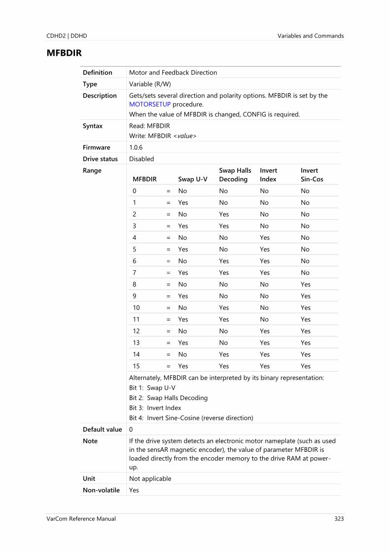
CDHD2 | DDHD Variables and Commands
VarCom Reference Manual 323
MFBDIR
Definition Motor and Feedback Direction
Type Variable (R/W)
Description Gets/sets several direction and polarity options. MFBDIR is set by the
MOTORSETUP procedure.
When the value of MFBDIR is changed, CONFIG is required.
Syntax Read: MFBDIR
Write: MFBDIR <value>
Firmware 1.0.6
Drive status Disabled
Range
MFBDIR Swap U-V
Swap Halls
Decoding
Invert
Index
Invert
Sin-Cos
0 = No No No No
1 = Yes No No No
2 = No Yes No No
3 = Yes Yes No No
4 = No No Yes No
5 = Yes No Yes No
6 = No Yes Yes No
7 = Yes Yes Yes No
8 = No No No Yes
9 = Yes No No Yes
10 = No Yes No Yes
11 = Yes Yes No Yes
12 = No No Yes Yes
13 = Yes No Yes Yes
14 = No Yes Yes Yes
15 = Yes Yes Yes Yes
Alternately, MFBDIR can be interpreted by its binary representation:
Bit 1: Swap U-V
Bit 2: Swap Halls Decoding
Bit 3: Invert Index
Bit 4: Invert Sine-Cosine (reverse direction)
Default value 0
Note If the drive system detects an electronic motor nameplate (such as used
in the sensAR magnetic encoder), the value of parameter MFBDIR is
loaded directly from the encoder memory to the drive RAM at power-
up.
Unit Not applicable
Non-volatile Yes

Variables and Commands CDHD2 | DDHD
324 VarCom Reference Manual
Related DIR
MOTORSETUP
MPHASE
PFB
V
EtherCAT
CANopen
202Bh, sub-index 0
Panel P 0 0 1 9

CDHD2 | DDHD Variables and Commands
VarCom Reference Manual 325
MFBMODE
Definition Motor Feedback Mode
Type Variable (R/W)
Description Enables/disables the resolution enhancement mechanism.
MFBMODE is applicable only for incremental encoders
(FEEDBACKTYPE 2, MENCTYPE 0, 1, 2, 3, 4, 6).
When MFBMODE is enabled PFB is displayed with a decimal fraction.
When the value of MFBMODE is changed, CONFIG is required.
Syntax Read: MFBMODE
Write: MFBMODE <value>
Firmware 1.0.6
Drive status Disabled
Range 0 = Resolution enhancement disabled
1 = Resolution enhancement enabled
2 = Encoder interpolation is not performed, and there is no
compensation for deviations from the 90-degree phase shift
Default value 1
Unit Not applicable
Non-volatile Yes
Related FEEDBACKTYPE
MENCTYPE
EtherCAT
CANopen
202Dh, sub-index 0
Panel P 2 0 2 6
Variables and Commands CDHD2 | DDHD
326 VarCom Reference Manual
MFOLD
Definition Motor Foldback Status
Type Variable (R)
Description Indicates whether the motor foldback limit (MIFOLD) has dropped
below the application current limits (ILIM).
Syntax MFOLD
Firmware 1.0.6
Drive status Enabled | Disabled
Range 0 = Foldback limit above ILIM
1 = Foldback limit below ILIM
Default value Not applicable
Unit Not applicable
Non-volatile No
Related
ILIM
MIFOLD
MIFOLDFTHRESH
MIFOLDWTHRESH
EtherCAT
CANopen
202Eh, sub-index 0
Panel P 3 0 1 2

CDHD2 | DDHD Variables and Commands
VarCom Reference Manual 327
MFOLDD
Definition Motor Foldback Delay Time
Type Variable (R/W)
Description Gets/sets the time delay for motor foldback. This is the amount of time
that the system current can exceed MICONT before the drive enters the
motor foldback state (MFOLD 1).
The timing units assume a worst-case scenario, in which the drive is
applying MIPEAK current. A current level that is less than MIPEAK can be
allowed for longer time.
Syntax Read: MFOLDD
Write: MFOLDD <value>
Firmware 1.0.6
Drive status Disabled
Range 1 to 2400
Default value 5.000
Note If the drive system detects an electronic motor nameplate (such as used
in the sensAR magnetic encoder), the value of parameter MFOLDD is
loaded directly from the encoder memory to the drive RAM at power-
up.
Unit second
Non-volatile Yes
Related MFOLDDIS
MFOLDR
MFOLDT
MICONT
MIPEAK
EtherCAT
CANopen
202Fh, sub-index 0
Panel P 3 0 1 3
Variables and Commands CDHD2 | DDHD
328 VarCom Reference Manual
MFOLDDIS
Definition Motor Foldback Disable
Type Variable (R/W)
Description Gets/sets a value that defines whether motor foldback protection is
activated.
Syntax Read: MFOLDDIS
Write: MFOLDDIS <value>
Firmware 1.0.6
Drive status Disabled
Range 0 = Motor foldback protection activated.
1 = Motor foldback protection not activated.
Default value 0
Unit Not applicable
Non-volatile Yes
Related MFOLD
MFOLDD
MFOLDR
MFOLDT
MICONT
MIFOLD
MIPEAK
EtherCAT
CANopen
2030h, sub-index 0
Panel P 3 0 1 4
CDHD2 | DDHD Variables and Commands
VarCom Reference Manual 329
MFOLDF
Definition Motor Foldback Factor
Type Variable (R/W)
Description MFOLDF is used to increase the effective continuous current setting of
the motor (MICONT) for the motor foldback protection mechanism.
When MFOLDF>1, the effective MICONT=MFOLDF MICONT.
Syntax Read: MFOLDF
Write: MFOLDF <value>
Firmware 1.4.4
Drive status Disabled
Range 1 to 1.5
Default value 1
Note If the drive system detects an electronic motor nameplate (such as used
in the sensAR magnetic encoder), the value of parameter MFOLDF is
loaded directly from the encoder memory to the drive RAM at power-
up.
Unit Not applicable
Non-volatile Yes
Related MFOLDDIS
MFOLDT
MICONT
EtherCAT
CANopen
Not applicable
Panel P 3 0 1 5
Variables and Commands CDHD2 | DDHD
330 VarCom Reference Manual
MFOLDR
Definition Motor Foldback Recovery Time
Type Variable (R)
Description Gets the recovery time for motor foldback.
After the drive enters the motor foldback state (MFOLD=1), and the
current folds back to MICONT, this is the minimum amount of time that
the current must be held at 0 before it can be MIPEAK for the full
MFOLDD time.
Note MFOLDR is a read only parameter, calculated from MIPEAK, MICONT,
MFOLDD, and MFOLDT.
Since MIPEAK and MICONT have a default value of 0, the initial value of
MFOLDR is 0.001. Once proper values are set for MIPEAK and MICONT,
MFOLDR gets a valid value.
Syntax MFOLDR
Firmware 1.0.6
Drive status Disabled
Range Not applicable
Default value Not applicable
Unit second
Non-volatile No
Related MFOLDD
MFOLDDIS
MFOLDT
MICONT
MIPEAK
EtherCAT
CANopen
2031h, sub-index 0
Panel P 3 0 1 6

CDHD2 | DDHD Variables and Commands
VarCom Reference Manual 331
MFOLDT
Definition Motor Foldback Time Constant
Type Variable (R/W)
Description Gets/sets the time constant for motor foldback.
After the drive enters the motor foldback state (MFOLD 1), this variable
defines how long it will take the drive to reduce the system current level
to MICONT.
Syntax Read: MFOLDT
Write: MFOLDT <value>
Firmware 1.0.6
Drive status Disabled
Range 1 to 1200
Default value 5.000
Note If the drive system detects an electronic motor nameplate (such as used
in the sensAR magnetic encoder), the value of parameter MFOLDT is
loaded directly from the encoder memory to the drive RAM at power-
up.
Unit second
Non-volatile Yes
Related MFOLDD
MFOLDDIS
MFOLDR
MICONT
MIPEAK
EtherCAT
CANopen
2032h, sub-index 0
Panel P 3 0 1 7

Variables and Commands CDHD2 | DDHD
332 VarCom Reference Manual
MICONT
Definition Motor Continuous Current
Type Variable (R/W)
Description Gets/sets the motor’s continuous rated current.
When the value of MICONT is changed, CONFIG is required.
Note MICONT and MIPEAK have a factory default setting of 0. Once the
values of MICONT and MIPEAK are set, the value of MIFOLD is set
accordingly.
Syntax Read: MICONT
Write: MICONT <value>
Firmware 1.0.6
Drive status Disabled
Range 0.1 to 150
Default value 0.000
Note If the drive system detects an electronic motor nameplate (such as used
in the sensAR magnetic encoder), the value of parameter MICONT is
loaded directly from the encoder memory to the drive RAM at power-
up.
Unit A (peak)
Non-volatile Yes
Related DICONT
ILIM
MFOLD
MIFOLD
MIPEAK
EtherCAT
CANopen
6075h, sub-index 0
Panel P 3 0 0 2

CDHD2 | DDHD Variables and Commands
VarCom Reference Manual 333
MIFOLD
Definition Motor Foldback Current
Type Variable (R)
Description Indicates the current limit derived from the motor foldback mechanism.
A foldback condition occurs when MIFOLD goes below ILIM.
This variable is useful for checking how close the current is to the
foldback limit.
The value of MIFOLD is calculated according to the values of MIPEAK
and MICONT
Syntax MIFOLD
Firmware 1.0.6
Drive status Enabled | Disabled
Range 0 to 300
Default value 0.000
Unit A
Non-volatile No
Related ILIM
MFOLD
MIFOLD
MIPEAK
MIFOLDFTHRESH
MIFOLDWTHRESH
EtherCAT
CANopen
2033h, sub-index 0
Panel P 3 0 1 8

Variables and Commands CDHD2 | DDHD
334 VarCom Reference Manual
MIFOLDFTHRESH
Definition Motor Foldback Fault Threshold
Type Variable (R/W)
Description Gets/sets the motor foldback fault threshold.
Note When the drive is paired with a PRO2 motor, and obtains data from the
electronic motor nameplate, the default value of MIFOLDFTHRESH is the
same as MICONT.
Syntax Read: MIFOLDFTHRESH
Write: MIFOLDFTHRESH <value>
Firmware 1.0.6
Drive status Enabled | Disabled
Range 0 to 300
Default value 0.000
Unit A
Non-volatile Yes
Related ILIM
MFOLD
MICONT
MIFOLD
MIFOLDWTHRESH
EtherCAT
CANopen
2034h, sub-index 0
Panel P 3 0 1 9

CDHD2 | DDHD Variables and Commands
VarCom Reference Manual 335
MIFOLDWTHRESH
Definition Motor Foldback Warning Threshold
Type Variable (R/W)
Description Gets/sets the motor foldback fault warning threshold.
Note When the drive is paired with a PRO2 motor, and obtains data from the
electronic motor nameplate, the default value of MIFOLDWTHRESH is
the same as MIPEAK.
Syntax Read: MIFOLDWTHRESH
Write: MIFOLDWTHRESH <value>
Firmware 1.0.6
Drive status Enabled | Disabled
Range 0 to 300
Default value 0.000
Unit A
Non-volatile Yes
Related ILIM
MFOLD
MIFOLD
MIFOLDFTHRESH
MIPEAK
EtherCAT
CANopen
2035h, sub-index 0

Variables and Commands CDHD2 | DDHD
336 VarCom Reference Manual
MIPEAK
Definition Motor Peak Current
Type Variable (R/W)
Description Gets/sets the motor’s peak rated current.
When the value of MIPEAK is changed, CONFIG is required.
Note MIPEAK and MICONT have a factory default setting of 0. Once the
values of MIPEAK and MICONT are set, the value of MIFOLD is set
accordingly.
Syntax Read: MIPEAK
Write: MIPEAK <value>
Firmware 1.0.6
Drive status Disabled
Range 0.1 to 300
Default value 0.000
Note If the drive system detects an electronic motor nameplate (such as used
in the sensAR magnetic encoder), the value of parameter MIPEAK is
loaded directly from the encoder memory to the drive RAM at power-
up.
Unit A
Non-volatile Yes
Related DIPEAK
ILIM
IMAX
MICONT
MIFOLD
EtherCAT
CANopen
2036h, sub-index 0
Panel P 3 0 0 3

CDHD2 | DDHD Variables and Commands
VarCom Reference Manual 337
MJ
Definition Rotor Inertia
Type Variable (R/W)
Description Gets/sets the motor’s rotor inertia (rotary motors).
The motor rotor inertia (MJ) and the load moment of inertia ratio (LMJR)
define the total system moment of inertia.
When the value of MJ is changed, CONFIG is required.
Syntax Read: MJ
Write: MJ <value>
Firmware 1.0.6
Drive status Disabled
Range 0.00 to 2000000.00
Default value 0.020
Note If the drive system detects an electronic motor nameplate (such as used
in the sensAR magnetic encoder), the value of parameter MJ is loaded
directly from the encoder memory to the drive RAM at power-up.
Unit kg-m2×10-3
Non-volatile Yes
Related LMJR
MKT
VELCONTROLMODE
EtherCAT
CANopen
2037h, sub-index 0

Variables and Commands CDHD2 | DDHD
338 VarCom Reference Manual
MKF
Definition Force Constant for Linear Motor
Type Variable (R/W)
Description Gets/sets the linear motor force constant (Kf), in metric units, for linear
motors.
This parameter is the equivalent of Torque Constant (MKT) for rotary
motors.
This value is used for current loop controller design, KCBEMF,
compensation algorithm, and standard pole-placement velocity
controller design (VELCONTROLMODE 2 or 4).
When the value of MKF is changed, CONFIG is required.
Note Applicable only for drives that support linear servo motors.
Syntax Read: MKF
Write: MKF <value>
Firmware 1.0.6
Drive status Disabled
Range 0.001 to 1000
Default value 0.016
Unit N/A
Non-volatile Yes
Related MKT
MMASS
MOTORTYPE
MPITCH
EtherCAT
CANopen
2038h, sub-index 0
Panel P 3 0 0 8
CDHD2 | DDHD Variables and Commands
VarCom Reference Manual 339
MKT
Definition Torque Constant
Type Variable (R/W)
Description Gets/sets the motor’s torque constant (Kt) in metric units. This value is
used for current loop controller design, KCBEMF, compensation
algorithm, and standard pole-placement velocity controller design
(VELCONTROLMODE 2 or 4).
When the value of MKT is changed, CONFIG is required.
Syntax Read: MKT
Write: MKT <value>
Firmware 1.0.6
Drive status Disabled
Range Drive supporting rotary motor: 0.001 to 3
Drive supporting linear and rotary motors: 0.001 to 65
Default value 0.016
Note If the drive system detects an electronic motor nameplate (such as used
in the sensAR magnetic encoder), the value of parameter MKT is loaded
directly from the encoder memory to the drive RAM at power-up.
Unit Nm/A
Non-volatile Yes
Related KCBEMF
LMJR
MJ
VELCONTROLMODE
EtherCAT
CANopen
2039h, sub-index 0
Panel P 3 0 0 7

Variables and Commands CDHD2 | DDHD
340 VarCom Reference Manual
ML
Definition Motor Inductance
Type Variable (R/W)
Description Gets/sets the motor’s minimum line-to-line inductance. This variable is
used for current loop controller design and as an input to the vector
control algorithms.
When the value of ML is changed, CONFIG is required.
Syntax Read: ML
Write: ML <value>
Firmware 1.0.6
Drive status Disabled
Range 0.001 to 1000
Default value 0.000
Note If the drive system detects an electronic motor nameplate (such as used
in the sensAR magnetic encoder), the value of parameter ML is loaded
directly from the encoder memory to the drive RAM at power-up.
Unit mH
Non-volatile Yes
Related KCP
VBUS
EtherCAT
CANopen
203Ah, sub-index 0
Panel P 1 3 0 9
CDHD2 | DDHD Variables and Commands
VarCom Reference Manual 341
MLGAINC
Definition Adaptive Gain at Continuous Motor Current
Type Variable (R/W)
Description Gets/sets the current loop adaptive gain value at continuous motor
current (MICONT). MLGAINC and MLGAINP define the adaptive gain
algorithm that is based on motor current.
When the value of MLGAINP is changed, CONFIG is required.
Syntax Read: MLGAINC
Write: MLGAINC <value>
Firmware 1.0.6
Drive status Disabled
Range 0.1 to 1
Default value 1.000
Unit Not applicable
Non-volatile Yes
Related ML
MLGAINP
EtherCAT
CANopen
203Bh, sub-index 0
Panel P 1 3 0 8

Variables and Commands CDHD2 | DDHD
342 VarCom Reference Manual
MLGAINP
Definition Adaptive Gain at Peak Motor Current
Type Variable (R/W)
Description Get/sets the current loop adaptive gain value at peak motor current
(MIPEAK). MLGAINC and MLGAINP define the adaptive gain algorithm
that is based on motor current.
When the value of MLGAINP is changed, CONFIG is required.
Syntax Read: MLGAINP
Write: MLGAINP <value>
Firmware 1.0.6
Drive status Disabled
Range 0.1 to 1.0
Default value 1.000
Unit Not applicable
Non-volatile Yes
Related ML
MLGAINC
EtherCAT
CANopen
203Ch, sub-index 0
Panel P 1 3 0 7

CDHD2 | DDHD Variables and Commands
VarCom Reference Manual 343
MMASS
Definition Mass of Linear Motor Without Load
Type Variable (R/W)
Description Gets/sets the mass of the linear motor carriage without any additional
payload. It is used as the base for estimating the total moving mass.
Note Applicable only for drives that support linear servo motors.
Syntax Read: MMASS
Write: MMASS <value>
Firmware 1.0.6
Drive status Enabled | Disabled
Range 0 to 100
Default value 0.000
Unit kg
Non-volatile Yes
Related MJ
MKF
MOTORTYPE
MPITCH
EtherCAT
CANopen
203Dh, sub-index 0

Variables and Commands CDHD2 | DDHD
344 VarCom Reference Manual
MODMODE
Definition Position Modulo Mode
Type Variable (R/W)
Description Enables/disables the position modulo.
When MODMODE is enabled, PFB and PCMD roll over the limits set by
PROTARY.
MODMODE has no effect when used with linear motors.
Syntax Read: MODMODE
Write: MODMODE <value>
Firmware 1.15.xx. Updated 1.41.9.
Drive status Disabled
Range 0 = Position modulo mode disabled.
1 = Position modulo mode enabled; MOVEABS by shortest path.
3 = Position modulo mode enabled; MOVEABS in positive direction
only.
5 = Position modulo mode enabled; MOVEABS in negative direction
only.
Default value 0
Unit Not applicable
Non-volatile Yes
Related MOVEABS
PROTARY
EtherCAT
CANopen
214Eh, sub-index 0

CDHD2 | DDHD Variables and Commands
VarCom Reference Manual 345
MOTORCOMMTYPE
Definition Motor Commutation Type
Type Variable (R/W)
Description Gets/sets a variable that defines the type of motor commutation
When the value of MOTOCOMMTYPE is changed, CONFIG is required.
Syntax Read: MOTORCOMMTYPE
Write: MOTORCOMMTYPE <value>
Firmware 1.2.12
Drive status Disabled
Range 0 = Brushless motor
1 = Brush motor
2 = DC and voice coil motors
Default value 0
Unit Not applicable
Non-volatile Yes
Related ELECTANGLE
FEEDBACKTYPE
MENCTYPE
MOTORTYPE
EtherCAT
CANopen
203Eh, sub-index 0
Panel P 3 0 1 1

Variables and Commands CDHD2 | DDHD
346 VarCom Reference Manual
MOTORNAME
Definition Motor Name
Type Variable (R/W)
Description Gets/sets the name assigned to the motor.
The name may contain up to 20 alphanumeric characters.
A quotation mark (“) always precedes the name.
Additional valid characters for use in the text string:
( ) / - . :
Syntax Read: MOTORNAME
Write: MOTORNAME <text>
Firmware 1.0.6
Drive status Enabled | Disabled
Range Not applicable
Default value “
Note If the drive system detects an electronic motor nameplate (such as used
in the sensAR magnetic encoder), the value of parameter MOTORNAME
is loaded directly from the encoder memory to the drive RAM at power-
up.
Unit Not applicable
Non-volatile Yes
Related DRIVENAME
FACTORYRESTORE
MOTORTYPE
CANopen 203Fh, sub-index 0
Panel P 3 0 0 0

CDHD2 | DDHD Variables and Commands
VarCom Reference Manual 347
MOTORSETUP
Definition Motor Setup Command
Type Command
Description Runs an automatic procedure for setting commutation related variables.
The procedure involves finding the electrical phase and detecting the
direction of motor movement, Hall switches and index crossing.
MOTORSETUP sets MFBDIR, MENCRES, MPOLES, MPHASE, MENCZPOS.
The procedure takes approximately 30 seconds and a motor rotation of
about one revolution is expected.
While the Motor Setup procedure is in progress (even when the drive is
disabled), the digital display shows A t 1 .
When the procedure finishes successfully, the display returns to its
normal state.
If the procedure fails, the digital display shows – 5 .
The motor setup routine can be used for the following configurations:
⚫ Encoders with square-wave quadrature signals:
FEEDBACKTYPE 2 with:
MENCTYPE 0, 1, 2, 3, 4, 6, 11
⚫ Encoders with sine signals:
FEEDBACKTYPE 3 with:
MENCTYPE 0, 1, 2, 3, 4, 6, 9
MENCTYPE 10
MENCTYPE 11
⚫ Communication-only encoders:
FEEDBACKTYPE 6
FEEDBACKTYPE 7
FEEDBACKTYPE 11
FEEDBACKTYPE 12
FEEDBACKTYPE 14
FEEDBACKTYPE 16
⚫ Resolver:
FEEDBACKTYPE 1
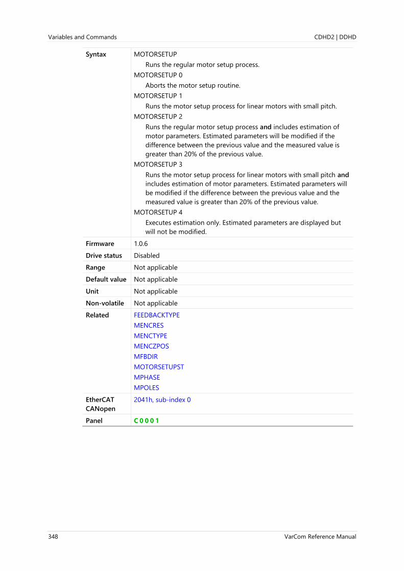
Variables and Commands CDHD2 | DDHD
348 VarCom Reference Manual
Syntax MOTORSETUP
Runs the regular motor setup process.
MOTORSETUP 0
Aborts the motor setup routine.
MOTORSETUP 1
Runs the motor setup process for linear motors with small pitch.
MOTORSETUP 2
Runs the regular motor setup process and includes estimation of
motor parameters. Estimated parameters will be modified if the
difference between the previous value and the measured value is
greater than 20% of the previous value.
MOTORSETUP 3
Runs the motor setup process for linear motors with small pitch and
includes estimation of motor parameters. Estimated parameters will
be modified if the difference between the previous value and the
measured value is greater than 20% of the previous value.
MOTORSETUP 4
Executes estimation only. Estimated parameters are displayed but
will not be modified.
Firmware 1.0.6
Drive status Disabled
Range Not applicable
Default value Not applicable
Unit Not applicable
Non-volatile Not applicable
Related FEEDBACKTYPE
MENCRES
MENCTYPE
MENCZPOS
MFBDIR
MOTORSETUPST
MPHASE
MPOLES
EtherCAT
CANopen
2041h, sub-index 0
Panel C 0 0 0 1

CDHD2 | DDHD Variables and Commands
VarCom Reference Manual 349
MOTORSETUPST
Definition Motor Setup Status
Type Command
Description Reports the internal stages of the MOTORSETUP procedure together
with the message that includes the running state, actions taken or
failure cause.
Syntax MOTORSETUPST
Firmware 1.0.6
Drive status Disabled
Range Not applicable; see Example below
Default value Not applicable; see Example below
Unit Not applicable; see Example below
Non-volatile Not applicable
Example -->motorsetupst
Motor Setup Not Issued
Stage: 0/51
-->
Example -->motorsetupst
Motor Setup Active
Stage: 20/51
-->motorsetupst
Motor Setup Active
Stage: 23/51
-->motorsetupst
Motor Setup Active
Stage: 24/36
-->motorsetupst
Motor Setup Succeeded
Current Pulse: 125 mA 195 ms
Stage: 0/36
-->
Related MOTORSETUP
PHASEFINDST
EtherCAT
CANopen
2042h, sub-index 0

Variables and Commands CDHD2 | DDHD
350 VarCom Reference Manual
MOTORTYPE
Definition Motor Type
Type Variable (R/W)
Description Gets/sets a value that defines the motor type.
When the value of MOTORTYPE is changed, CONFIG is required.
Syntax Read: MOTORTYPE
Write: MOTORTYPE <value>
Firmware 1.0.6
Drive status Disabled
Range 0 = Rotary motor
2 = Linear motor
Note: Applicable for drive models that support linear and rotary
servo motors.
Default value 0
Note If the drive system detects an electronic motor nameplate (such as used
in the sensAR magnetic encoder), the value of parameter MOTORTYPE
is loaded directly from the encoder memory to the drive RAM at power-
up.
Unit Not applicable
Non-volatile Yes
Related FEEDBACKTYPE
EtherCAT
CANopen
2024h, sub-index 0
Panel P 3 0 0 1

CDHD2 | DDHD Variables and Commands
VarCom Reference Manual 351
MOVEABS
Definition Move Absolute Command
Type Command
Description Executes an absolute position movement according to the acceleration
settings that are in effect.
STOPPED and PEINPOS indicate completion of motion.
Syntax MOVEABS {distance} {velocity}
Firmware 1.0.6
Drive status Enabled
Range Not applicable
Default value Not applicable
Unit Not applicable
Non-volatile Not applicable
Related MB
MOVEINC
OPMODE
PFB
EtherCAT
CANopen
Not applicable
Panel C 0 0 1 0

Variables and Commands CDHD2 | DDHD
352 VarCom Reference Manual
MOVEINC
Definition Move Incremental Command
Type Command
Description Executes an incremental position movement according to the
acceleration settings that are in effect.
If blending_mode = 1 and MOVEINC is issued while a movement is in
progress, the current movement is discontinued, and the new
movement starts immediately.
If blending_mode = 2 or 3 and MOVEINC is issued while a movement is
in progress, the incremental move will be added to the position target
of the current move.
In all blending modes the final position is the summation of the target
positions of both the currently executed command and the newly issued
MOVEINC command.
STOPPED and PEINPOS indicate completion of motion.
Syntax MOVEINC {distance} {velocity} [blending_mode]
Note blending_mode is optional; if not specified, blending mode 2 is used.
Firmware 1.0.6
Drive status Enabled
Range distance = Not applicable
velocity = Not applicable
blending_mode:
1 = MOVEINC is executed immediately.
2 = MOVEINC is executed at the end of the currently executed
movement (default value).
3 = MOVEINC is executed at the end of the currently executed
movement without stopping.
Default value Not applicable
Unit Not applicable
Non-volatile Yes
Related MB
MOVEABS
OPMODE
PFB
EtherCAT
CANopen
Not applicable
Panel C 0 0 1 1

CDHD2 | DDHD Variables and Commands
VarCom Reference Manual 353
MOVEINCCOUNTER
Definition Move Incremental Iterations
Type Variable (R/W)
Description Gets/sets the number of repetitions of an incremental movement to be
executed.
Syntax Read: MOVEINCCOUNTER
Write: MOVEINCCOUNTER <value>
Firmware 1.0.6
Drive status Enabled | Disabled
Range 0 to 65535
Default value 1
Unit Not applicable
Non-volatile Yes
Related MB
MBST
MOVEINCDIST1
MOVEINCSPEED1
EtherCAT
CANopen
Not applicable

Variables and Commands CDHD2 | DDHD
354 VarCom Reference Manual
MOVEINCDELAY
Definition Move Incremental Delay
Type Variable (R/W)
Description The delay between the preset incremental moves.
Syntax Read: MOVEINCDELAY
Write: MOVEINCDELAY <value>
Firmware 1.3.2
Drive status Enabled | Disabled
Range 0 to 100000
Default value 0
Unit ms
Non-volatile Yes
Related MB
MBST
MOVEINCCOUNTER
EtherCAT
CANopen
Not applicable

CDHD2 | DDHD Variables and Commands
VarCom Reference Manual 355
MOVEINCDIST1
Definition Move Incremental Distance 1
Type Variable (R/W)
Description Gets/sets the first incremental move distance for the motion buffer
cycle.
Syntax Read: MOVEINCDIST1
Write: MOVEINCDIST1 <value>
Firmware 1.0.6
Drive status Enabled | Disabled
Range If MOTORTYPE 0 (Rotary): ±(231 -1) [rev]
If MOTORTYPE 2 (Linear): ±(231 -1) [pitch]
Default value 0
Unit If MOTORTYPE 0 (Rotary):
UNITSROTPOS 0 = rev
UNITSROTPOS 1 = count
UNITSROTPOS 2 = deg
If MOTORTYPE 2 (Linear):
UNITSLINPOS 0 = pitch
UNITSLINPOS 1 = count
UNITSLINPOS 3 = mm
Non-volatile Yes
Related MB
MBST
MOVEINCCOUNTER
MOVEINCSPEED1
EtherCAT
CANopen
Not applicable
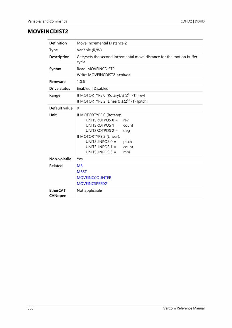
Variables and Commands CDHD2 | DDHD
356 VarCom Reference Manual
MOVEINCDIST2
Definition Move Incremental Distance 2
Type Variable (R/W)
Description Gets/sets the second incremental move distance for the motion buffer
cycle.
Syntax Read: MOVEINCDIST2
Write: MOVEINCDIST2 <value>
Firmware 1.0.6
Drive status Enabled | Disabled
Range If MOTORTYPE 0 (Rotary): ±(231 -1) [rev]
If MOTORTYPE 2 (Linear): ±(231 -1) [pitch]
Default value 0
Unit If MOTORTYPE 0 (Rotary):
UNITSROTPOS 0 = rev
UNITSROTPOS 1 = count
UNITSROTPOS 2 = deg
If MOTORTYPE 2 (Linear):
UNITSLINPOS 0 = pitch
UNITSLINPOS 1 = count
UNITSLINPOS 3 = mm
Non-volatile Yes
Related MB
MBST
MOVEINCCOUNTER
MOVEINCSPEED2
EtherCAT
CANopen
Not applicable

CDHD2 | DDHD Variables and Commands
VarCom Reference Manual 357
MOVEINCSPEED1
Definition Move Incremental Speed 1
Type Variable (R/W)
Description Gets/sets the first incremental move velocity for the motion buffer cycle.
The actual move speed value will not exceed VLIM.
Syntax Read: MOVEINCSPEED1
Write: MOVEINCSPEED1 <value>
Firmware 1.0.6
Drive status Enabled | Disabled
Range 0 to VLIM
Default value If MOTORTYPE 0 (Rotary):
UNITSROTVEL 0 = 0.167
UNITSROTVEL 1 = 10.000
UNITSROTVEL 2 = 60.000
If MOTORTYPE 2 (Linear):
UNITSLINVEL 1 = 5.333
Unit If MOTORTYPE 0 (Rotary):
If UNITSROTVEL 0 = rps
If UNITSROTVEL 1 = rpm
If UNITSROTVEL 2 = deg/s
If MOTORTYPE 2 (Linear):
UNITSLINVEL 1 = mm/s
Non-volatile Yes
Related MB
MBST
MOVEINCCOUNTER
MOVEINCDIST1
EtherCAT
CANopen
Not applicable

Variables and Commands CDHD2 | DDHD
358 VarCom Reference Manual
MOVEINCSPEED2
Definition Move Incremental Speed 2
Type Variable (R/W)
Description Gets/sets the second incremental move velocity for the motion buffer
cycle. The actual move speed value will not exceed VLIM.
Syntax Read: MOVEINCSPEED2
Write: MOVEINCSPEED2 <value>
Firmware 1.0.6
Drive status Enabled | Disabled
Range 0 to VLIM
Default value If MOTORTYPE 0 (Rotary):
UNITSROTVEL 0 = 0.167
UNITSROTVEL 1 = 10.000
UNITSROTVEL 2 = 60.000
If MOTORTYPE 2 (Linear):
UNITSLINVEL 1 = 5.333
Unit If MOTORTYPE 0 (Rotary):
If UNITSROTVEL 0 = rps
If UNITSROTVEL 1 = rpm
If UNITSROTVEL 2 = deg/s
If MOTORTYPE 2 (Linear):
UNITSLINVEL 1 = mm/s
Non-volatile Yes
Related MB
MBST
MOVEINCCOUNTER
MOVEINCDIST2
EtherCAT
CANopen
Not applicable
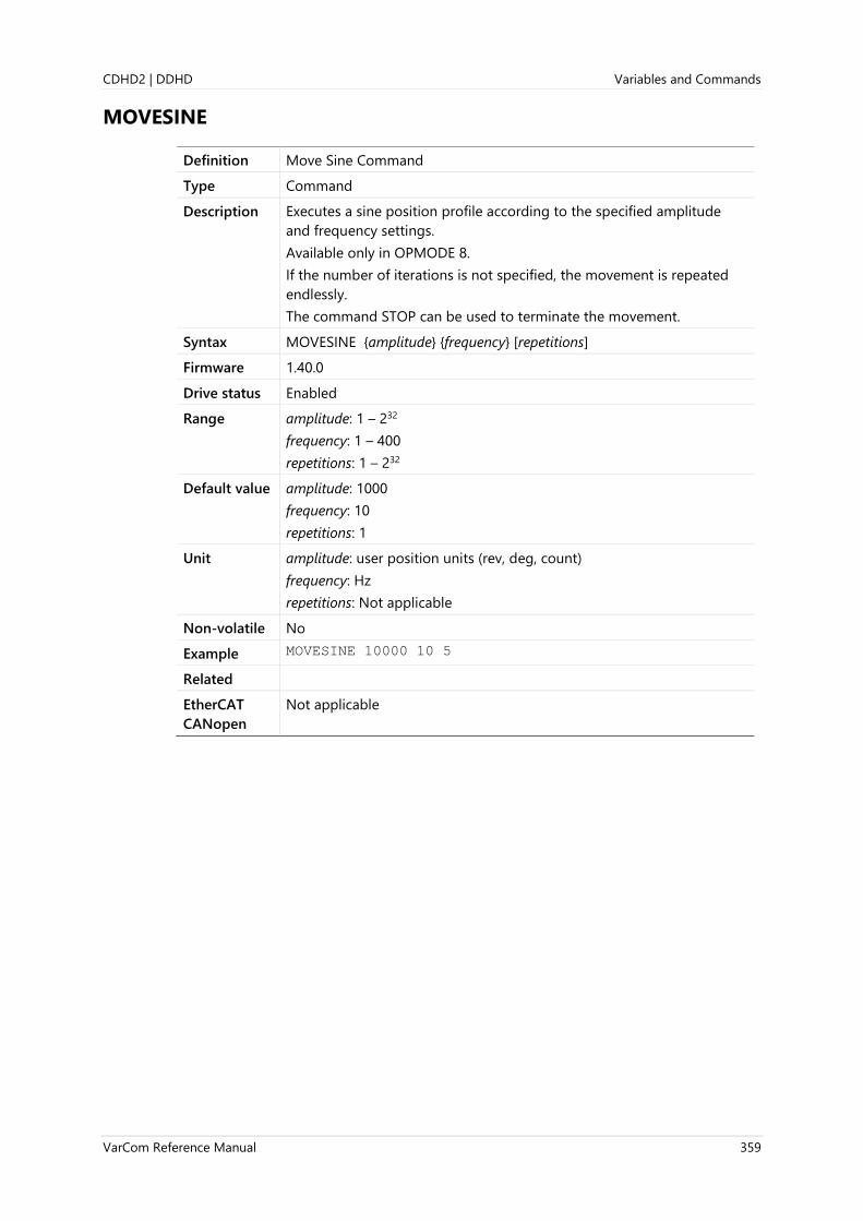
CDHD2 | DDHD Variables and Commands
VarCom Reference Manual 359
MOVESINE
Definition Move Sine Command
Type Command
Description Executes a sine position profile according to the specified amplitude
and frequency settings.
Available only in OPMODE 8.
If the number of iterations is not specified, the movement is repeated
endlessly.
The command STOP can be used to terminate the movement.
Syntax MOVESINE {amplitude} {frequency} [repetitions]
Firmware 1.40.0
Drive status Enabled
Range amplitude: 1 – 232
frequency: 1 – 400
repetitions: 1 – 232
Default value amplitude: 1000
frequency: 10
repetitions: 1
Unit amplitude: user position units (rev, deg, count)
frequency: Hz
repetitions: Not applicable
Non-volatile No
Example MOVESINE 10000 10 5
Related
EtherCAT
CANopen
Not applicable

Variables and Commands CDHD2 | DDHD
360 VarCom Reference Manual
MOVESMOOTHAVG
Definition Position Command Moving Average Filter
Type Variable (R/W)
Description Gets/sets the moving average filter.
The moving average filter can be applied to a position or velocity
reference command in order to smooth the command and shape it into
an S-curve profile.
Syntax Read: MOVESMOOTHAVG
Write: MOVESMOOTHAVG <value>
Firmware 1.4.4
Drive status Enabled (motor must be at standstill) | Disabled
Range 0.25 to 128
Default value 4
Unit ms
Non-volatile Yes
Related MOVESMOOTHMODE
EtherCAT
CANopen
2108h, sub-index 0
Panel P 1 1 0 2

CDHD2 | DDHD Variables and Commands
VarCom Reference Manual 361
MOVESMOOTHLPFHZ
Definition Position Command Move Low Pass Filter
Type Variable (R/W)
Description Gets/sets the low pass filter for position command move.
Syntax Read: MOVESMOOTHLPFHZ
Write: MOVESMOOTHLPFHZ <value>
Firmware 1.2.12
Drive status Enabled (motor must be at standstill) | Disabled
Range 1 to 5000
Default value 5000
Unit Hz
Non-volatile Yes
Related ACC
DEC
MOVEABS
MOVEINC
EtherCAT
CANopen
202Ch, sub-index 0
Panel P 1 1 0 3

Variables and Commands CDHD2 | DDHD
362 VarCom Reference Manual
MOVESMOOTHMODE
Definition Position Command Smoothing Mode
Type Variable (R/W)
Description Defines the method of smoothing for the position command.
Note To apply a smoothing filter to an external reference command, such as
P&D or EtherCAT/CANopen, certain bits in MOVESMOOTHSRC must
first be set.
Syntax Read: MOVESMOOTHMODE
Write: MOVESMOOTHMODE <value>
Firmware 1.3.2
Drive status Disabled
Range 0 = No smoothing of profile
1 = Low pass filter (LPF) smoothing of profile based on
MOVESMOOTHLPFHZ
2 = S-curve smoothing according to MOVESMOOTHAVG
Default 2
Unit Not applicable
Non-volatile Yes
Related MOVEABS
MOVEINC
MOVESMOOTHAVG
MOVESMOOTHLPFHZ
MOVESMOOTHSRC
EtherCAT
CANopen
2109h, sub-index 0
Panel P 1 1 0 0

CDHD2 | DDHD Variables and Commands
VarCom Reference Manual 363
MOVESMOOTHSRC
Definition Position Command Smoothing Source
Type Variable (R/W)
Description Defines the position command smoothing source.
This is a bit-wise parameter, hence the range 0 to 15.
bit 0: smooth on PTP (1=yes, 0=no)
bit 1: smooth on gearing
bit 2: smooth on fieldbus
bit 3: smooth during halt (limit switch, for example) if the halted move is
also smoothed.
Syntax Read: MOVESMOOTHSRC
Write: MOVESMOOTHSRC <value>
Firmware 1.15.xx
Drive status Disabled
Range 0 to 15
Default value 15
Unit Not applicable
Non-volatile Yes
Related MOVESMOOTHAVG
MOVESMOOTHLPFHZ
MOVESMOOTHMODE
EtherCAT
CANopen
Not applicable
Panel P 1 1 0 1

Variables and Commands CDHD2 | DDHD
364 VarCom Reference Manual
MPHASE
Definition Commutation Offset
Type Variable (R/W)
Description Gets/sets the feedback phase relative to the standard commutation
table.
This variable can be used to compensate for feedback offset and should
be set to 0 if there is no resolver offset. Changing MPHASE shifts the
internal commutation table without affecting the feedback reading.
Syntax Read: MPHASE
Write: MPHASE <value>
Firmware 1.0.6
Drive status Disabled
Range 0 to 359
Default value 0
Unit Electrical degree
Note If the drive system detects an electronic motor nameplate (such as used
in the sensAR magnetic encoder), the value of parameter MPHASE is
loaded directly from the encoder memory to the drive RAM at power-
up.
Non-volatile Yes
Related PHASEFIND
ZERO
EtherCAT
CANopen
2043h, sub-index 0
Panel P 0 0 2 0
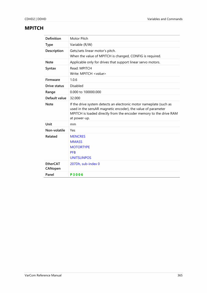
CDHD2 | DDHD Variables and Commands
VarCom Reference Manual 365
MPITCH
Definition Motor Pitch
Type Variable (R/W)
Description Gets/sets linear motor’s pitch.
When the value of MPITCH is changed, CONFIG is required.
Note Applicable only for drives that support linear servo motors.
Syntax Read: MPITCH
Write: MPITCH <value>
Firmware 1.0.6
Drive status Disabled
Range 0.000 to 100000.000
Default value 32.000
Note If the drive system detects an electronic motor nameplate (such as
used in the sensAR magnetic encoder), the value of parameter
MPITCH is loaded directly from the encoder memory to the drive RAM
at power-up.
Unit mm
Non-volatile Yes
Related MENCRES
MMASS
MOTORTYPE
PFB
UNITSLINPOS
EtherCAT
CANopen
207Dh, sub-index 0
Panel P 3 0 0 6
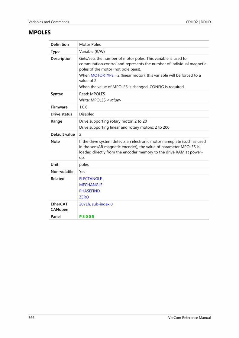
Variables and Commands CDHD2 | DDHD
366 VarCom Reference Manual
MPOLES
Definition Motor Poles
Type Variable (R/W)
Description Gets/sets the number of motor poles. This variable is used for
commutation control and represents the number of individual magnetic
poles of the motor (not pole pairs).
When MOTORTYPE =2 (linear motor), this variable will be forced to a
value of 2.
When the value of MPOLES is changed, CONFIG is required.
Syntax Read: MPOLES
Write: MPOLES <value>
Firmware 1.0.6
Drive status Disabled
Range Drive supporting rotary motor: 2 to 20
Drive supporting linear and rotary motors: 2 to 200
Default value 2
Note If the drive system detects an electronic motor nameplate (such as used
in the sensAR magnetic encoder), the value of parameter MPOLES is
loaded directly from the encoder memory to the drive RAM at power-
up.
Unit poles
Non-volatile Yes
Related ELECTANGLE
MECHANGLE
PHASEFIND
ZERO
EtherCAT
CANopen
207Eh, sub-index 0
Panel P 3 0 0 5

CDHD2 | DDHD Variables and Commands
VarCom Reference Manual 367
MR
Definition Motor Resistance
Type Variable (R/W)
Description The motor resistance.
When the value of MR is changed, CONFIG is required.
Syntax Read: MR
Write: MR <value>
Firmware 1.2.12
Drive status Disabled
Range 0 to 75
Default value 0.000
Note If the drive system detects an electronic motor nameplate (such as used
in the sensAR magnetic encoder), the value of parameter MR is loaded
directly from the encoder memory to the drive RAM at power-up.
Unit Ohm
Non-volatile Yes
Related ML
EtherCAT
CANopen
207Fh, sub-index 0
Panel P 3 0 1 0

Variables and Commands CDHD2 | DDHD
368 VarCom Reference Manual
MRESPOLES
Definition Motor Resolver Poles
Type Variable (R/W)
Description Gets/sets the number of individual poles in the resolver feedback
device. This variable is used for the commutation function, as well as for
velocity feedback scaling, and represents the number of individual
poles, not pole pairs.
When the value of MRESPOLES is changed, CONFIG is required.
Syntax Read: MRESPOLES
Write: MRESPOLES <value>
Firmware 1.0.6
Drive status Disabled
Range 2 to 80
Default value 2
Unit poles
Non-volatile Yes
Related FEEDBACKTYPE
HWPOS
MECHANGLE
EtherCAT
CANopen
2080h, sub-index 0
Panel P 2 0 2 7

CDHD2 | DDHD Variables and Commands
VarCom Reference Manual 369
MSGPROMPT
Definition Drive Messages and Prompts
Type Variable (R/W)
Description Defines whether drive messages and prompts are enabled or disabled.
MSGPROMPT 1 is required for proper operation of the graphic interface
software.
MSGPROMPT 0 will result in a loss of communication with the graphic
interface software. Use with caution.
Syntax Read: MSGPROMPT
Write: MSGPROMPT <value>
Firmware 1.0.6
Drive status Enabled | Disabled
Range 0 = Messages and prompts disabled.
1 = Messages and prompts enabled.
Default value 1
Unit Not applicable
Non-volatile Yes
Related ADDR
ECHO
EtherCAT
CANopen
Not applicable
Panel P 6 0 1 2

Variables and Commands CDHD2 | DDHD
370 VarCom Reference Manual
MSININT
Definition Motor Sine Interpolation
Type Read/Write
Description MSININT is used to define the resolution of the analog signals of sine
encoders (SinCos), and sets the interpolation level of the drive. The
equivalent number of counts per revolution is calculated from:
2MSININT × MENCRES
The equivalent number of counts per revolution is limited by:
2MSININT × MENCRES ≤ 230
When the value of MSININT is changed, CONFIG is required.
Syntax Read: MSININT
Write: MSININT <value>
Firmware 1.4.4
Drive status Disabled
Range 2 to 16
Default value 16
Unit bits
Non-volatile Yes
Related FEEDBACKTYPE
MENCRES
MENCTYPE
MPITCH
EtherCAT
CANopen
Not applicable
Panel P 2 0 0 3
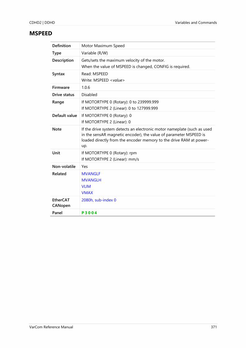
CDHD2 | DDHD Variables and Commands
VarCom Reference Manual 371
MSPEED
Definition Motor Maximum Speed
Type Variable (R/W)
Description Gets/sets the maximum velocity of the motor.
When the value of MSPEED is changed, CONFIG is required.
Syntax Read: MSPEED
Write: MSPEED <value>
Firmware 1.0.6
Drive status Disabled
Range If MOTORTYPE 0 (Rotary): 0 to 239999.999
If MOTORTYPE 2 (Linear): 0 to 127999.999
Default value If MOTORTYPE 0 (Rotary): 0
If MOTORTYPE 2 (Linear): 0
Note If the drive system detects an electronic motor nameplate (such as used
in the sensAR magnetic encoder), the value of parameter MSPEED is
loaded directly from the encoder memory to the drive RAM at power-
up.
Unit If MOTORTYPE 0 (Rotary): rpm
If MOTORTYPE 2 (Linear): mm/s
Non-volatile Yes
Related MVANGLF
MVANGLH
VLIM
VMAX
EtherCAT
CANopen
2080h, sub-index 0
Panel P 3 0 0 4
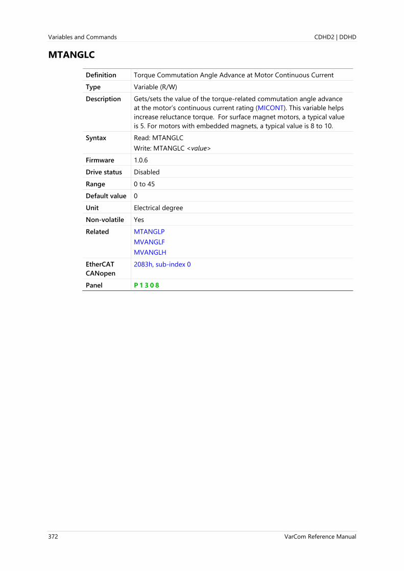
Variables and Commands CDHD2 | DDHD
372 VarCom Reference Manual
MTANGLC
Definition Torque Commutation Angle Advance at Motor Continuous Current
Type Variable (R/W)
Description Gets/sets the value of the torque-related commutation angle advance
at the motor’s continuous current rating (MICONT). This variable helps
increase reluctance torque. For surface magnet motors, a typical value
is 5. For motors with embedded magnets, a typical value is 8 to 10.
Syntax Read: MTANGLC
Write: MTANGLC <value>
Firmware 1.0.6
Drive status Disabled
Range 0 to 45
Default value 0
Unit Electrical degree
Non-volatile Yes
Related MTANGLP
MVANGLF
MVANGLH
EtherCAT
CANopen
2083h, sub-index 0
Panel P 1 3 0 8

CDHD2 | DDHD Variables and Commands
VarCom Reference Manual 373
MTANGLP
Definition Torque Commutation Angle Advance at Motor Peak Current
Type Variable (R/W)
Description Gets/sets the value of the torque-related commutation angle advance
at the motor’s peak current (MIPEAK). This variable helps increase
reluctance torque. For surface magnet motors, a typical value is 10. For
motors with embedded magnets, a typical value is 23 to 25.
Syntax Read: MTANGLP
Write: MTANGLP <value>
Firmware 1.0.6
Drive status Disabled
Range 0 to 45
Default value 0
Unit Electrical degree
Non-volatile Yes
Related MTANGLC
MVANGLF
MVANGLH
EtherCAT
CANopen
2084h, sub-index 0
Panel P 1 3 0 9

Variables and Commands CDHD2 | DDHD
374 VarCom Reference Manual
MTPMODE
Definition Electronic Motor Nameplate Mode
Type Variable (R/W)
Description MTPMODE defines whether motor and feedback data is obtained from
the feedback device’s non-volatile memory, referred to as an electronic
motor type plate (MTP). The electronic motor nameplate enables
automatic setup of motor and current loop parameters.
The drive is factory-configured without motor parameters. If the drive
system detects an electronic motor nameplate (such as used in the
sensAR magnetic encoder), certain motor and feedback parameters are
loaded directly from the encoder memory to the drive RAM after
power-up.
If MTPMODE 0, motor and current loop parameters cannot be
manipulated by user.
Syntax Read: MTPMODE
Write: MTPMODE <value>
Firmware 1.15.xx
Drive status Disabled
Range 0 = Electronic motor nameplate not in use
3 = sensAR and HIPERFACE encoders
4 = Tamagawa single turn encoder (such as used on Welling motors)
Default value 3
Unit Not applicable
Non-volatile Yes
Related FEEDBACKTYPE
EtherCAT
CANopen
Not applicable
Panel P 3 0 2 0
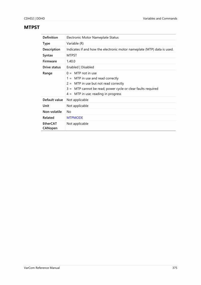
CDHD2 | DDHD Variables and Commands
VarCom Reference Manual 375
MTPST
Definition Electronic Motor Nameplate Status
Type Variable (R)
Description Indicates if and how the electronic motor nameplate (MTP) data is used.
Syntax MTPST
Firmware 1.40.0
Drive status Enabled | Disabled
Range 0 = MTP not in use
1 = MTP in use and read correctly
2 = MTP in use but not read correctly
3 = MTP cannot be read; power cycle or clear faults required
4 = MTP in use; reading in progress
Default value Not applicable
Unit Not applicable
Non-volatile No
Related MTPMODE
EtherCAT
CANopen
Not applicable

Variables and Commands CDHD2 | DDHD
376 VarCom Reference Manual
MTTURNRESET
Definition Multi-turn Encoder Reset
Type Command
Description Resets the position counter of an absolute multi-turn encoder, and
clears battery low voltage fault.
Syntax MTTURNRESET
Firmware 1.41.x
Drive status Disabled
Range Not applicable
Default value Not applicable
Unit Not applicable
Non-volatile Not applicable
Related FEEDBACKTYPE
MENCTYPE
EtherCAT
CANopen
2186h, sub-index 0
Panel C 0 0 0 7

CDHD2 | DDHD Variables and Commands
VarCom Reference Manual 377
MVANGLF
Definition Velocity Commutation Angle Advance at Motor Maximum Speed
Type Variable (R/W)
Description Gets/sets the value of the velocity-related commutation angle advance
to be used when the motor is operating at motor maximum speed
(MSPEED). Between MSPEED/2 and MSPEED, the angle advance will be
linearly interpolated based on MVANGLH and MVANGLF.
When the value of MVANGLF is changed, CONFIG is required.
Syntax Read: MVANGLF
Write: MVANGLF <value>
Firmware 1.0.6
Drive status Disabled
Range 0 to 90
Default value 0
Unit Electrical degree
Non-volatile Yes
Related MTANGLC
MTANGLP
MVANGLH
EtherCAT
CANopen
2085h, sub-index 0

Variables and Commands CDHD2 | DDHD
378 VarCom Reference Manual
MVANGLH
Definition Velocity Commutation Angle Advance at Motor Maximum Speed/2
Type Variable (R/W)
Description Gets/sets the value of the velocity-related commutation angle advance
to be used when the motor is operating at motor maximum speed/2
(MSPEED/2). Between 0 rpm and MSPEED/2, the angle advance will be
linearly interpolated based on MVANGLH .
When the value of MVANGLH is changed, CONFIG is required
Syntax Read: MVANGLH
Write: MLVANGH <value>
Firmware 1.0.6
Drive status Disabled
Range 0 to 90
Default value 0
Unit Electrical degree
Non-volatile Yes
Related MTANGLC
MTANGLP
MVANGLF
EtherCAT
CANopen
2086h, sub-index 0

CDHD2 | DDHD Variables and Commands
VarCom Reference Manual 379
MVEL
Definition Motor Velocity
Type Variable (R)
Description The velocity according to the feedback device on the motor.
Syntax MVEL
Firmware 2.0.x
Drive status Enabled | Disabled
Range Not applicable
Default value Not applicable
Unit If MOTORTYPE 0 (Rotary):
If UNITSROTVEL 0 = rps
If UNITSROTVEL 1 = rpm
If UNITSROTVEL 2 = deg/s
If MOTORTYPE 2 (linear):
UNITSLINVEL 1 = mm/s
Non-volatile No
Related SFB
SFBMODE
EtherCAT
CANopen
2143h, sub-index 0
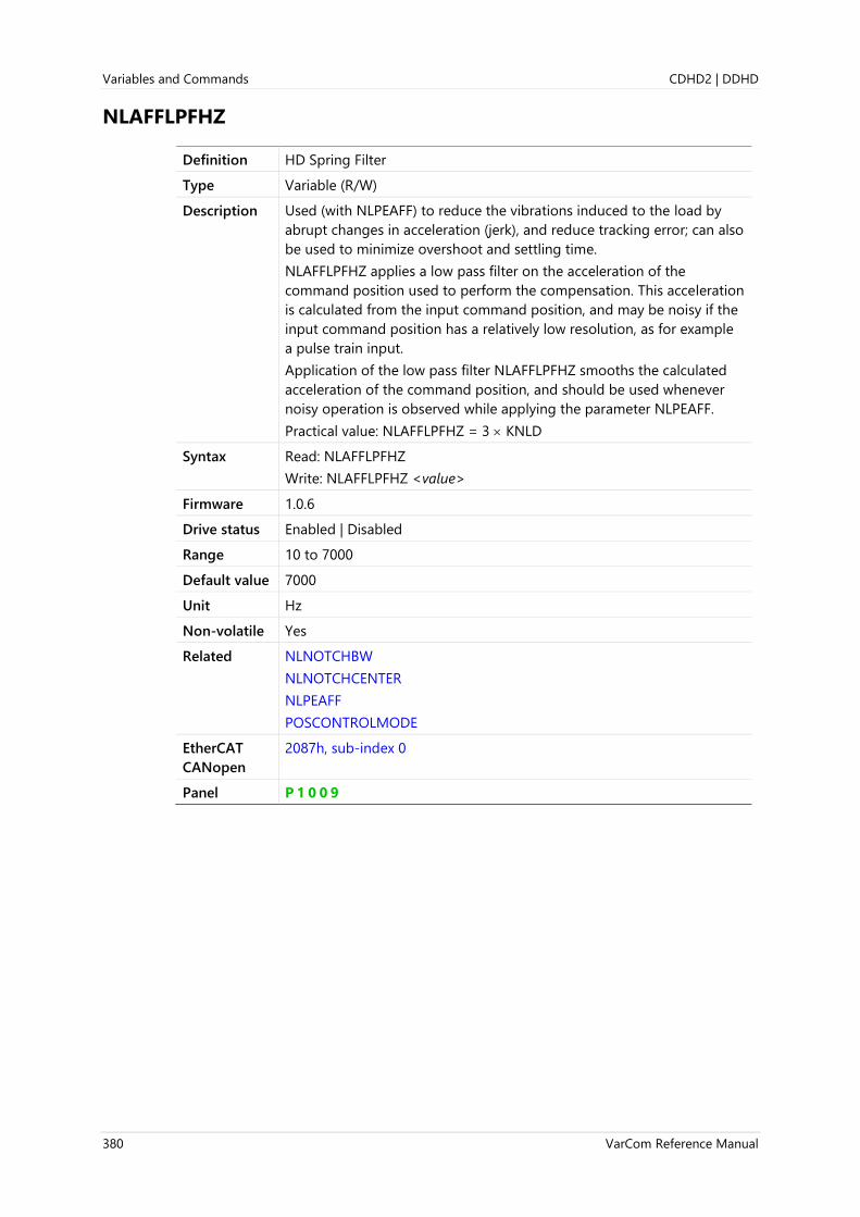
Variables and Commands CDHD2 | DDHD
380 VarCom Reference Manual
NLAFFLPFHZ
Definition HD Spring Filter
Type Variable (R/W)
Description Used (with NLPEAFF) to reduce the vibrations induced to the load by
abrupt changes in acceleration (jerk), and reduce tracking error; can also
be used to minimize overshoot and settling time.
NLAFFLPFHZ applies a low pass filter on the acceleration of the
command position used to perform the compensation. This acceleration
is calculated from the input command position, and may be noisy if the
input command position has a relatively low resolution, as for example
a pulse train input.
Application of the low pass filter NLAFFLPFHZ smooths the calculated
acceleration of the command position, and should be used whenever
noisy operation is observed while applying the parameter NLPEAFF.
Practical value: NLAFFLPFHZ = 3 KNLD
Syntax Read: NLAFFLPFHZ
Write: NLAFFLPFHZ <value>
Firmware 1.0.6
Drive status Enabled | Disabled
Range 10 to 7000
Default value 7000
Unit Hz
Non-volatile Yes
Related NLNOTCHBW
NLNOTCHCENTER
NLPEAFF
POSCONTROLMODE
EtherCAT
CANopen
2087h, sub-index 0
Panel P 1 0 0 9

CDHD2 | DDHD Variables and Commands
VarCom Reference Manual 381
NLANTIVIBGAIN
Definition HD Anti-Vibration 1 Filter – Gain
Type Variable (R/W)
Description Gets/sets the HD position control loop anti-vibration module 1 filter –
gain.
Syntax Read: NLANTIVIBGAIN
Write: NLANTIVIBGAIN <value>
Firmware 1.3.2
Drive status Enabled | Disabled
Range 0 to 10000
Default value 0.000
Unit (Rad × 10−3)
Nm
Non-volatile Yes
Related NLANTIVIBGAIN2
NLANTIVIBGAIN3
NLANTIVIBHZ
NLANTIVIBQ3
NLANTIVIBSHARP
EtherCAT
CANopen
200Ch, sub-index 0

Variables and Commands CDHD2 | DDHD
382 VarCom Reference Manual
NLANTIVIBGAIN2
Definition HD Anti-Vibration 2 Filter – Gain
Type Variable (R/W)
Description Gets/sets the HD position control loop anti-vibration module 3 filter –
gain
Syntax Read: NLANTIVIBGAIN2
Write: NLANTIVIBGAIN2 <value>
Firmware 1.3.2
Drive status Enabled | Disabled
Range 0 to 99
Default value 0.000
Unit Not applicable
Non-volatile Yes
Related NLANTIVIBGAIN
NLANTIVIBGAIN3
NLANTIVIBHZ
NLANTIVIBQ3
NLANTIVIBSHARP
EtherCAT
CANopen
200Ah, sub-index 0
Panel P 1 0 1 7

CDHD2 | DDHD Variables and Commands
VarCom Reference Manual 383
NLANTIVIBGAIN3
Definition HD Anti-Vibration 3 Filter – Gain
Type Variable (R/W)
Description Gets/sets the HD position control loop anti-vibration module 3 filter –
gain
Syntax Read: NLANTIVIBGAIN3
Write: NLANTIVIBGAIN3 <value>
Firmware 1.15.xx
Drive status Enabled | Disabled
Range 0 to 6
Default value 0.000
Unit Not applicable
Non-volatile Yes
Related NLANTIVIBGAIN
NLANTIVIBGAIN2
NLANTIVIBHZ
NLANTIVIBQ3
NLANTIVIBSHARP
EtherCAT
CANopen
Not applicable
Panel P 1 0 2 0

Variables and Commands CDHD2 | DDHD
384 VarCom Reference Manual
NLANTIVIBHZ
Definition HD Anti-Vibration 1 Filter – Center Frequency
Type Variable (R/W)
Description Gets/sets the HD position control loop anti-vibration module 1 filter –
center frequency.
Syntax Read: NLANTIVIBHZ
Write: NLANTIVIBHZ <value>
Firmware 1.3.2
Drive status Enabled | Disabled
Range 5 to 400
Default value 400.000
Unit Hz
Non-volatile Yes
Related NLANTIVIBGAIN
NLANTIVIBGAIN2
NLANTIVIBGAIN3
NLANTIVIBQ3
NLANTIVIBSHARP
EtherCAT
CANopen
2096h, sub-index 0

CDHD2 | DDHD Variables and Commands
VarCom Reference Manual 385
NLANTIVIBHZ2
Definition HD Anti-Vibration 2 Filter – Center Frequency
Type Variable (R/W)
Description Gets/sets the HD position control loop anti-vibration module 2 filter –
center frequency.
Syntax Read: NLANTIVIBHZ2
Write: NLANTIVIBHZ2 <value>
Firmware 1.3.2
Drive status Enabled | Disabled
Range 5 to 800
Default value 400.000
Unit Hz
Non-volatile Yes
Related NLANTIVIBGAIN
NLANTIVIBHZ
NLANTIVIBHZ3
NLANTIVIBQ3
NLANTIVIBSHARP
EtherCAT
CANopen
2097h, sub-index 0
Panel P 1 0 1 8

Variables and Commands CDHD2 | DDHD
386 VarCom Reference Manual
NLANTIVIBHZ3
Definition HD Anti-Vibration 3 Filter – Center Frequency
Type Variable (R/W)
Description Gets/sets the HD position control loop anti-vibration module 3 filter –
center frequency.
Syntax Read: NLANTIVIBHZ3
Write: NLANTIVIBHZ3 <value>
Firmware 1.15.xx
Drive status Enabled | Disabled
Range 5 to 800
Default value 400.000
Unit Hz
Non-volatile Yes
Related NLANTIVIBGAIN
NLANTIVIBHZ
NLANTIVIBHZ2
NLANTIVIBQ3
NLANTIVIBSHARP
EtherCAT
CANopen
Not applicable
Panel P 1 0 2 1

CDHD2 | DDHD Variables and Commands
VarCom Reference Manual 387
NLANTIVIBLMJR
Definition HD Anti-Vibration – Load to Motor Inertia Ratio
Type Variable (R/W)
Description Gets/sets the HD position control loop anti-vibration filter – load to
motor inertia ratio.
Syntax Read: NLANTIVIBLMJR
Write: NLANTIVIBLMJR <value>
Firmware 1.3.2
Drive status Enabled | Disabled
Range 0 to 600
Default value 0.000
Unit Not applicable
Non-volatile Yes
Related
EtherCAT
CANopen
210Bh, sub-index 0

Variables and Commands CDHD2 | DDHD
388 VarCom Reference Manual
NLANTIVIBN
Definition HD Anti-Vibration Filter – Divider
Type Variable (R/W)
Description Gets/sets the HD position control loop anti-vibration filter – divider
Syntax Read: NLANTIVIBN
Write: NLANTIVIBN <value>
Firmware 1.3.2
Drive status Enabled | Disabled
Range 0.01 to 100
Default value 2.000
Unit Not applicable
Non-volatile Yes
Related
EtherCAT
CANopen
210Ch, sub-index 0

CDHD2 | DDHD Variables and Commands
VarCom Reference Manual 389
NLANTIVIBQ3
Definition HD Anti-Vibration Filter - Factor
Type Variable (R/W)
Description Gets/sets the HD position control loop anti-vibration filter – factor
Syntax Read: NLANTIVIBQ3
Write: NLANTIVIBQ3 <value>
Firmware 1.15.xx
Drive status Enabled | Disabled
Range 1 to 10
Default value 1.000
Unit Not applicable
Non-volatile Yes
Related NLANTIVIBGAIN
NLANTIVIBHZ
NLANTIVIBSHARP
NLANTIVIBSHARP2
NLANTIVIBSHARP3
EtherCAT
CANopen
Not applicable
Variables and Commands CDHD2 | DDHD
390 VarCom Reference Manual
NLANTIVIBSHARP
Definition HD Anti-Vibration 1 Filter – Sharpness
Type Variable (R/W)
Description Gets/sets the HD position control loop anti-vibration module 1 filter –
sharpness.
Syntax Read: NLANTIVIBSHARP
Write: NLANTIVIBSHARP <value>
Firmware 1.3.2
Drive status Enabled | Disabled
Range 0.01 to 10
Default value 0.500
Unit Not applicable
Non-volatile Yes
Related NLANTIVIBGAIN
NLANTIVIBHZ
NLANTIVIBQ3
NLANTIVIBSHARP2
NLANTIVIBSHARP3
EtherCAT
CANopen
200Bh, sub-index 0
Panel P 1 0 1 6

CDHD2 | DDHD Variables and Commands
VarCom Reference Manual 391
NLANTIVIBSHARP2
Definition HD Anti-Vibration 2 Filter – Sharpness
Type Variable (R/W)
Description Gets/sets the HD position control loop anti-vibration module 2 filter –
sharpness.
Syntax Read: NLANTIVIBSHARP2
Write: NLANTIVIBSHARP2 <value>
Firmware 1.3.2
Drive status Enabled | Disabled
Range 0.01 to 10
Default value 0.500
Unit Not applicable
Non-volatile Yes
Related NLANTIVIBGAIN
NLANTIVIBHZ
NLANTIVIBQ3
NLANTIVIBSHARP
NLANTIVIBSHARP3
EtherCAT
CANopen
212Dh, sub-index 0
Panel P 1 0 1 9

Variables and Commands CDHD2 | DDHD
392 VarCom Reference Manual
NLANTIVIBSHARP3
Definition HD Anti-Vibration 3 Filter – Sharpness
Type Variable (R/W)
Description Gets/sets the HD position control loop anti-vibration module 3 filter –
sharpness.
Syntax Read: NLANTIVIBSHARP3
Write: NLANTIVIBSHARP3 <value>
Firmware 1.15.xx
Drive status Enabled | Disabled
Range 0.01 to 10
Default value 0.200
Unit Not applicable
Non-volatile Yes
Related NLANTIVIBGAIN
NLANTIVIBHZ
NLANTIVIBQ3
NLANTIVIBSHARP
NLANTIVIBSHARP2
EtherCAT
CANopen
Not applicable
Panel P 1 0 2 2

CDHD2 | DDHD Variables and Commands
VarCom Reference Manual 393
NLFILTDAMPING
Definition HD Current Filter Low Pass Damping
Type Variable (R/W)
Description NLFILTDAMPING is used in the HD control loop to maintain the
bandwidth of the filter up to the cutoff frequency.
A practical value = 30 < NLFILTDAMPING< 95
Ideally, NLFILTDAMPING = maximum value
Following are recommended NLFILTT1 and NLFILTDAMPING values for
current low pass filter cutoff frequency (-3db).
Filter Frequency [Hz] NLFILTT1 [ms] NLFILTDAMPING [%]
100 82.18506 97.26105
200 20.82976 94.59509
300 9.384389 91.99826
400 5.350447 89.46693
500 3.470506 86.99772
600 2.442406 84.58745
700 1.818363 82.23314
800 1.410669 79.93199
900 1.129338 77.68135
1000 0.926812 75.47875
1100 0.776016 73.32184
1200 0.660606 71.2084
1300 0.570238 69.13634
1400 0.498098 67.10369
1500 0.439552 65.10856
1600 0.391354 63.14919
1700 0.35118 61.22387
1800 0.317322 59.33102
1900 0.28851 57.46909
2000 0.263777 55.63665
Syntax Read: NLFILTDAMPING
Write: NLFILTDAMPING <value>
Firmware 1.0.6
Drive status Enabled | Disabled
Range 0 to 100
Default value 30
Unit %
Non-volatile Yes
Related NLFILTT1
POSCONTROLMODE

Variables and Commands CDHD2 | DDHD
394 VarCom Reference Manual
EtherCAT
CANopen
2060h, sub-index 0
Panel P 1 0 1 1

CDHD2 | DDHD Variables and Commands
VarCom Reference Manual 395
NLFILTMODE
Definition HD Current Filter – First Notch Filter Mode
Type Variable (R/W)
Description Gets/sets the value that defines the mode of first notch filter for the
HD control loop.
Note This parameter is applicable only in HD control loop.
Syntax Read: NLFILTMODE
Write: NLFILTMODE <value>
Firmware 2.15.x
Drive status Enabled | Disabled
Range 0 = Notch filter; sets NLNOTCHCENTER as notch center frequency and
NLNOTCHBW as notch frequency width.
1 = Advanced notch filter for velocity loop output. This filter has a
phase change limited to 50. Sets NLNOTCHCENTER as notch
center frequency and NLNOTCHBW as notch frequency width.
Default value 0
Unit Not applicable
Non-volatile Yes
Related NLNOTCHBW
NLNOTCHCENTER
EtherCAT
CANopen
2216h, sub-index 0

Variables and Commands CDHD2 | DDHD
396 VarCom Reference Manual
NLFILTMODE2
Definition HD Current Filter – Second Notch Filter Mode
Type Variable (R/W)
Description Gets/sets the value that defines the mode of second notch filter for the
HD control loop.
Note This parameter is applicable only in HD control loop.
Syntax Read: NLFILTMODE2
Write: NLFILTMODE2 <value>
Firmware 2.15.x
Drive status Enabled | Disabled
Range 0 = Notch filter; sets NLNOTCH2CENTER as notch center frequency
and NLNOTCH2BW as notch frequency width.
1 = Advanced notch filter. This filter has a phase change limited to 50
deg.; sets NLNOTCH2CENTER as notch center frequency and
NLNOTCH2BW as notch frequency width.
Default value 0
Unit Not applicable
Non-volatile Yes
Related NLNOTCH2BW
NLNOTCH2CENTER
EtherCAT
CANopen
2217h, sub-index 0

CDHD2 | DDHD Variables and Commands
VarCom Reference Manual 397
NLFILTT1
Definition HD Current Filter Low Pass Rise Time
Type Variable (R/W)
Description NLFILTT1 is used in the HD control loop to define the inverse of the
cutoff frequency.
Ideally, NLFILTT1 = minimum value
Note This parameter is applicable only in HD control loop.
Following are recommended NLFILTT1 and NLFILTDAMPING values for
current low pass filter cutoff frequency (-3db).
Filter Frequency [Hz] NLFILTT1 [ms] NLFILTDAMPING [%]
100 82.18506 97.26105
200 20.82976 94.59509
300 9.384389 91.99826
400 5.350447 89.46693
500 3.470506 86.99772
600 2.442406 84.58745
700 1.818363 82.23314
800 1.410669 79.93199
900 1.129338 77.68135
1000 0.926812 75.47875
1100 0.776016 73.32184
1200 0.660606 71.2084
1300 0.570238 69.13634
1400 0.498098 67.10369
1500 0.439552 65.10856
1600 0.391354 63.14919
1700 0.35118 61.22387
1800 0.317322 59.33102
1900 0.28851 57.46909
2000 0.263777 55.63665
Syntax Read: NLFILTT1
Write: NLFILTT1<value>
Firmware 1.0.6
Drive status Enabled | Disabled
Range 0 to 30
Default value 3.000
Unit ms
Non-volatile Yes
Related NLFILTDAMPING
POSCONTROLMODE

Variables and Commands CDHD2 | DDHD
398 VarCom Reference Manual
EtherCAT
CANopen
210Dh, sub-index 0
Panel P 1 0 1 0
CDHD2 | DDHD Variables and Commands
VarCom Reference Manual 399
NLMAXGAIN
Definition HD Maximum Adaptive Gain
Type Variable (R/W)
Description Autotuning automatically sets the variable gain according to the
encoder resolution. This is the recommended value.
Low resolution: wide range
(Example: 13 bit: NLMAXGAIN=2.7)
High resolution: narrow range
(Example: 22 bit: NLMAXGAIN=1.6)
Other resolutions can be extrapolated accordingly.
Syntax Read: NLMAXGAIN
Write: NLMAXGAIN <value>
Firmware 1.0.6
Drive status Enabled | Disabled
Range 1 to 5
Default value 1.600
Unit Not applicable
Non-volatile Yes
Related KNLP
KNLUSERGAIN
POSCONTROLMODE
EtherCAT
CANopen
208Ah, sub-index 0
Panel P 1 0 1 2

Variables and Commands CDHD2 | DDHD
400 VarCom Reference Manual
NLNOTCH2BW
Definition HD Current Filter – Second Notch Filter Bandwidth
Type Variable (R/W)
Description NLNOTCH2BW is used in the HD control loop to define the width
(sharpness) of an additional high frequency that is causing system
vibrations.
If not used, set NLNOTCHBW=0
Syntax Read: NLNOTCH2BW
Write: NLNOTCH2BW <value>
Firmware 1.0.6
Drive status Enabled | Disabled
Range 0 to 500
Default value 0
Unit Hz
Non-volatile Yes
Related NLNOTCH2CENTER
POSCONTROLMODE
EtherCAT
CANopen
208Bh, sub-index 0

CDHD2 | DDHD Variables and Commands
VarCom Reference Manual 401
NLNOTCH2CENTER
Definition HD Current Filter – Second Notch Filter Center
Type Variable (R/W)
Description NLNOTCH2CENTER is used in the HD control loop to block an
additional high frequency that is causing system vibrations.
Syntax Read: NLNOTCH2CENTER
Write: NLNOTCH2CENTER <value>
Firmware 1.0.6
Drive status Enabled | Disabled
Range 5 to 1800
Default value 100
Unit Hz
Non-volatile Yes
Related NLNOTCH2BW
POSCONTROLMODE
EtherCAT
CANopen
208Ch, sub-index 0
Panel P 1 0 1 5

Variables and Commands CDHD2 | DDHD
402 VarCom Reference Manual
NLNOTCHBW
Definition HD Current Filter – Notch Filter Bandwidth
Type Variable (R/W)
Description NLNOTCHBW is used in the HD control loop to define the width
(sharpness) of a high frequency that is causing system vibrations.
If not used, set NLNOTCHBW=0
Syntax Read: NLNOTCHBW
Write: NLNOTCHBW <value>
Firmware 1.0.6
Drive status Enabled | Disabled
Range 0 to 500
Default value 0
Unit Hz
Non-volatile Yes
Related NLNOTCH2CENTER
POSCONTROLMODE
EtherCAT
CANopen
2062h, sub-index 0
Panel P 1 0 1 4

CDHD2 | DDHD Variables and Commands
VarCom Reference Manual 403
NLNOTCHCENTER
Definition HD Current Filter – Notch Filter Center
Type Variable (R/W)
Description NLNOTCHCENTER is used in the HD control loop to block a high
frequency that is causing system vibrations.
Syntax Read: NLNOTCHCENTER
Write: NLNOTCHCENTER <value>
Firmware 1.0.6
Drive status Enabled | Disabled
Range 5 to 1800
Default value 100
Unit Hz
Non-volatile Yes
Related NLNOTCH2BW
POSCONTROLMODE
EtherCAT
CANopen
2061h, sub-index 0
Panel P 1 0 1 3

Variables and Commands CDHD2 | DDHD
404 VarCom Reference Manual
NLPEAFF
Definition HD Flexibility Compensation
Type Variable (R/W)
Description Used by the parameter NLPEDFFRATIO.
Used (with NLAFFLPHZ) to reduce the vibrations induced to the load by
abrupt changes in acceleration (jerk), and reduce tracking error; can also
be used to minimize overshoot and settling time.
NLPEAFF is set according to the rigidity of the system. Rigid systems
require a high value. Systems with high load inertia and flexible
couplings require lower values; the normal range is 400 to 30 Hz. If not
used, set to 5000 Hz.
Syntax Read: NLPEAFF
Write: NLPEAFF <value>
Firmware 1.0.6
Drive status Enabled | Disabled
Range 0 to 5000
Default value 5000.00
Unit Hz
Non-volatile Yes
Related NLPEDFFRATIO
NLAFFLPFHZ
POSCONTROLMODE
EtherCAT
CANopen
208Fh, sub-index 0
Panel P 1 0 0 8

CDHD2 | DDHD Variables and Commands
VarCom Reference Manual 405
NLPEDFFRATIO
Definition HD Acceleration/Deceleration Spring Filter Gain
Type Variable (R/W)
Description Determines the acceleration/deceleration spring filter gain according to
the value of NLPEDFFRATIO=<n>, as follows:
0 NLPEAFF used during acceleration.
NLPEAFF not used during deceleration.
0 < n < 1 NLPEAFF used during acceleration.
n NLPEAFF used during deceleration.
1 NLPEAFF used during both acceleration and
deceleration.
1 < n ≤ 2 NLPEAFF used during deceleration.
(2-n) NLPEAFF used during acceleration.
2 NLPEAFF used during deceleration.
NLPEAFF not used during acceleration.
Syntax Read: NLPEDFFRATIO
Write: NLPEDFFRATIO <value>
Firmware 1.2.12
Drive status Enabled | Disabled
Range 0 to 2
Default value 1
Unit Not applicable
Non-volatile Yes
Related ACC
NLPEAFF
NLPEDFFRATIO
EtherCAT
CANopen
2091h, sub-index 0
Variables and Commands CDHD2 | DDHD
406 VarCom Reference Manual
NLTFBW
Definition HD Current Filter – Low Pass Filter Bandwidth
Type Variable (R/W)
Description Gets/sets a user-defined frequency parameter. NLTFBW is used in the
HD control loop to define the output filter bandwidth.
Requires NLTFDESIGNMODE=1
Syntax Read: NLTFBW
Write: NLTFBW <value>
Firmware 2.0.x
Drive status Enabled | Disabled
Range 20 to 2000
Default value 1000
Unit Hz
Non-volatile Yes
Related NLTFDESIGNMODE
EtherCAT
CANopen
Not applicable

CDHD2 | DDHD Variables and Commands
VarCom Reference Manual 407
NLTFDESIGNMODE
Definition HD Current Filter – Low Pass Mode
Type Variable (R/W)
Description NLTFDESIGNMODE defines the controller design of the HD control loop
output filter. The controller design is either time-based (using NLFILTT1
and NLFILTDAMPING) or frequency-based design (using NLTFBW).
Syntax Read: NLTFDESIGNMODE
Write: NLTFDESIGNMODE <value>
Firmware 2.0.x
Drive status Enabled | Disabled
Range 0 = Design based on NLFILTT1 and NLFILTDAMPING parameters;
Used in firmware versions prior to 2.0.x
1 = Design based on NLTFBW parameter;
Used in firmware versions 2.0.x and later
Default value 0
Unit Not applicable
Non-volatile Yes
Related NLFILTDAMPING
NLFILTT1
NLTFBW
EtherCAT
CANopen
Not applicable

Variables and Commands CDHD2 | DDHD
408 VarCom Reference Manual
NLVELLIM
Definition HD Velocity Control Standstill Tolerance
Type Variable (R/W)
Description Applicable for use only in Analog Velocity operation mode (OPMODE 1)
with the HD velocity control (VELCONTROLMODE 5, 6).
Gets/sets a threshold value for the input command voltage. When the
input command voltage drops below NLVELLIM, the integral and
integral-derivative gains of the controller are reduced by half, hence
improving standstill stability.
Ideally, NLVELLIM should be set slightly above the analog input “0”
noise level.
Syntax Read: NLVELLIM
Write: NLVELLIM <value>
Firmware 1.4.4
Drive status Disabled
Range -3.815 to 3.815
Default value 0.000
Unit V
Non-volatile Yes
Related ANIN1VSCALE
OPMODE
VELCONTROLMODE
EtherCAT
CANopen
Not applicable
CDHD2 | DDHD Variables and Commands
VarCom Reference Manual 409
OPMODE
Definition Drive Operation Mode
Type Variable (R/W)
Description Gets/sets a value that defines the drive operation mode.
Syntax Read: OPMODE
Write: OPMODE <value>
Firmware 1.0.6
Drive status Disabled
Range 0 = Velocity control, using serial commands (Serial Velocity)
1 = Velocity control, using analog input (Analog Velocity)
2 = Current control, using serial commands (Serial Current)
3 = Current control, using analog input (Analog Current)
4 = Position control, using gearing input (Gearing/Pulse Train)
8 = Position control, using serial commands (Serial Position)
Default value 2: If an electronic motor nameplate (MTP) is not detected
8: If an electronic motor nameplate (MTP) is detected
Note Certain motor parameters are stored in the MTP and are loaded directly
from the encoder memory to the drive RAM at power-up.
PRO2 and PRHD2 motors are typically equipped with a sensAR encoder,
which has an MTP.
Unit Not applicable
Non-volatile Yes
Related ANIN2MODE
COMMODE
GEARMODE
POSCONTROLMODE
VELCONTROLMODE
EtherCAT
CANopen
Not applicable
Panel P 0 0 0 1
Variables and Commands CDHD2 | DDHD
410 VarCom Reference Manual
OPMODESWITCH
Definition Operation Mode Change While Drive Enabled
Type Variable (R/W)
Description The drive operation mode can be changed while the drive is enabled.
The parameter INMODE <input#> 32 is used to activate this
functionality.
OPMODESWITCH defines whether the switch to another operation
mode occurs immediately (on-the-fly) or whether a stop occurs (in
standstill) prior to the switch.
Standstill mode (OPMODESWITCH=0)
In this mode, the operation mode is switched as follows:
1. The drive receives OPMODE change request.
2. The drive initiates HOLD.
3. The drive waits for a standstill condition (with a timeout of
10 second).
4. After reaching standstill or after the timeout, the drive changes the
mode of operation;
If the change in operation mode is defined to occur after a stop, it is
important to define at the speed at which the motor is considered at
standstill.
Adjust parameters PEINPOS and PEINPOSTIME to achieve a standstill
state; for example: PEINPOS=0.025[rev] and PEINPOSTIME=50 [ms]. A
standstill condition will be generated if the motor does not move more
than 0.025 rev within 50 ms (that is, V=0.025[rev]/50[ms] = 0.5 [rps] =
30 [rpm]).
On-the-fly mode (OPMODESWITCH 1)
In this mode, the drive performs the actions needed to continue
executing the currently pending motion, such as applying the actual
velocity as a command velocity when switching to Velocity operation
mode.
Note that the motor continues moving according to the actual
torque/speed at the time the operation mode switch until a new
command values arrives in the drive.
Syntax Read: OPMODESWITCH
Write: OPMODESWITCH <value>
Firmware 1.40.0
Drive status Enabled | Disabled
Range 0 = Mode change at standstill
1 = Mode change on-the-fly
Default value 0
Unit Not applicable
Non-volatile Yes
CDHD2 | DDHD Variables and Commands
VarCom Reference Manual 411
Related IN32OPMODES
IN32SWITCH
INMODE
OPMODE
PEINPOS
PEINPOSTIME
EtherCAT
CANopen
Not applicable
Variables and Commands CDHD2 | DDHD
412 VarCom Reference Manual
OUT
Definition Output Status
Type Variable (R); (R/W in OUTMODE 0)
Description Gets/sets the state of a digital output.
Syntax Read: OUT <output#>
Write: OUT <output#> <value>
Firmware 1.0.6
Drive status Disabled
Range output# = 1 to 7
value:
0 = Output off
1 = Output on
Default value 0
Unit Not applicable
Non-volatile No
Exampled -->out 1
0
-->out 1 1
-->out 1
1
-->
Related OUTINV
OUTMODE
OUTPUTS
EtherCAT
CANopen
60FEh, sub-index 1
Panel d 0 0 0 6

CDHD2 | DDHD Variables and Commands
VarCom Reference Manual 413
OUTBRAKE
Definition Manual Brake by Output
Type Variable (R/W)
Description Gets/sets the state of the dedicated output that causes the motor brake
to engage.
Requires OUTBRAKEMODE=0.
Note Applicable only for CDHD2 400/480 VAC models with Brake interface
(P4).
Syntax Read: OUTBRAKE
Write: OUTBRAKE <value>
Firmware 1.41.0
Drive status Enabled | Disabled
Range 0 = Output off disengages the brake (normal polarity)
1 = Output on engages the brake (normal polarity)
Default value 0
Unit Not applicable
Non-volatile Yes
Related OUTBRAKEINV
OUTBRAKEMODE
OUTMODE
EtherCAT
CANopen
Not applicable
Panel P 4 0 4 1

Variables and Commands CDHD2 | DDHD
414 VarCom Reference Manual
OUTBRAKEINV
Definition Manual Brake by Output Inverse
Type Variable (R/W)
Description Inverts the polarity of the dedicated output that controls the motor
brake.
Note Applicable only for CDHD2 400/480 VAC models with Brake interface
(P4).
Syntax Read: OUTBRAKEINV
Write: OUTBRAKEINV <value>
Firmware 1.41.0
Drive status Enabled | Disabled
Range 0 = Normal polarity
1 = Inverts output polarity
Default value 1
Unit Not applicable
Non-volatile Yes
Related OUTBRAKE
OUTBRAKEMODE
EtherCAT
CANopen
Not applicable
Panel P 4 0 4 2

CDHD2 | DDHD Variables and Commands
VarCom Reference Manual 415
OUTBRAKEMODE
Definition Manual Brake by Output Mode
Type Variable (R/W)
Description Defines whether the motor brake is operated automatically by the drive
or manually by the user.
It may be necessary to control the motor brake manually in certain
instances, such as during replacement of a motor.
Note Applicable only for CDHD2 400/480 VAC models with Brake interface
(P4).
Syntax Read: OUTBRAKEMODE
Write: OUTBRAKEMODE <value>
Firmware 1.41.0
Drive status Enabled | Disabled
Range 0 = Manual control of motor brake
1 = Normal brake operation; motor brake disengaged when drive
enabled; motor break engaged when drive disabled.
Default value 1
Unit Not applicable
Non-volatile Yes
Related OUTBRAKE
OUTBRAKEINV
EtherCAT
CANopen
Not applicable
Panel P 4 0 4 3

Variables and Commands CDHD2 | DDHD
416 VarCom Reference Manual
OUTFLTLVL
Definition Force Digital Output State on Fault
Type Variable (R/W)
Description Used to force digital outputs to a certain state when the drive is
disabled due to a fault.
This command can be used to override the digital output mode during
a fault condition. It also overrides a potential inversion setting by the
user (see also OUTINV).
This is a bit-wise parameter; 2 bits define the behavior of a given
output:
Bits 0 and 1 define the behavior of output 1
Bits 2 and 3 define the behavior of output 2
Bits 4 and 5 define the behavior of output 3
Bits 6 and 7 define the behavior of output 4
Bits 8 and 9 define the behavior of output 5
Bits 10 and 11 define the behavior of output 6
Bits 12 and 13 define the behavior of output 7
Bit 0:
0 = During a fault, digital output 1 level is low (off)
1 = During a fault, digital output 1 level is high (on)
Bit 1:
0 = Digital output 1 is set according to the defined output mode.
1 = Digital output 1 is set to the state defined in bit 0
Bit 2:
0 = During a fault, digital output 2 level is low (off)
1 = During a fault, digital output 2 level is high (on)
Bit 3:
0 = Digital output 2 is set according to the defined output mode.
1 = Digital output 2 is set to the state defined in bit 2
and so on.
Syntax Read: OUTFLTLVL
Write: OUTFLTLVL <value>
Firmware 1.15.xx
Drive status Enabled | Disabled
Range 0 to 4294967295
Default value 0
Unit Not applicable
Non-volatile Yes

CDHD2 | DDHD Variables and Commands
VarCom Reference Manual 417
Example When a fault has occurred and the drive is disabled: Digital outputs 1
and 3 are 0 (off). Digital outputs 5 and 6 are 1 (on). The remaining
digital outputs function according to their dedicated output modes.
Setting: 0b00 11 11 00 10 00 10 = 0xF22 = 3874
-->OUTFLTLVL 3874
-->OUTFLTLVL
3874
-->
Related OUT
OUTMODE
OUTPUTS
EtherCAT
CANopen
2158h, sub-index 0
Panel P 4 0 4 4

Variables and Commands CDHD2 | DDHD
418 VarCom Reference Manual
OUTILVL1
Definition Current Level 1 for Digital Output Definition
Type Variable (R/W)
Description Gets/sets the first current level used for a condition that controls a
digital output.
Syntax Read: OUTILVL1
Write: OUTILVL1<value>
Firmware 1.0.6
Drive status Enabled | Disabled
Range 0 to 150
Default value 0.000
Unit A
Non-volatile Yes
Related OUTILVL2
OUTINV
OUTMODE
OUTPUTS
EtherCAT
CANopen
2099h, sub-index 0
Panel P 4 0 4 5

CDHD2 | DDHD Variables and Commands
VarCom Reference Manual 419
OUTILVL2
Definition Current Level 2 for Digital Output Definition
Type Variable (R/W)
Description Gets/sets the second current level used for a condition that controls a
digital output.
Syntax Read: OUTILVL2
Write: OUTILVL2<value>
Firmware 1.0.6
Drive status Enabled | Disabled
Range 0 to 150
Default value 0.000
Unit A
Non-volatile Yes
Related OUTILVL1
OUTINV
OUTMODE
OUTPUTS
EtherCAT
CANopen
209Ah, sub-index 0
Panel P 4 0 5 0
Variables and Commands CDHD2 | DDHD
420 VarCom Reference Manual
OUTINV
Definition Output Polarity Inversion
Type Variable (R/W)
Description Gets/sets the output polarity of each of the digital outputs.
Syntax Read: OUTINV <output#>
Write: OUTINV <output#> <value>
Firmware 1.0.6
Drive status Enabled | Disabled
Range output# = 1 to 7
value:
0 = Output not inverted
1 = Output inverted
Default value 0
Unit Not applicable
Non-volatile Yes
Example -->outinv 3
0
-->outinv 3 1
-->outinv 3
1
Related OUT
OUTMODE
OUTPUTS
EtherCAT
CANopen
209Bh, sub-index 1
Panel P 4 0 2 9 Output Inversion (output 1)
P 4 0 3 0 Output Inversion (output 2)
P 4 0 3 1 Output Inversion (output 3)
P 4 0 3 2 Output Inversion (output 4)
P 4 0 3 3 Output Inversion (output 5)
P 4 0 3 4 Output Inversion (output 6)
P 4 0 3 5 Output Inversion (output 7)

CDHD2 | DDHD Variables and Commands
VarCom Reference Manual 421
OUTMODE
Definition Output Mode
Type Variable (R/W)
Description Gets/sets a value that defines the condition that will activate the
specified digital output.
Syntax Read: OUTMODE <output#>
Write: OUTMODE <output#> <value>
Firmware 1.0.6
Drive status Enabled | Disabled
Range output# = 1 to 7
value:
0 = Idle
1 = Active (enabled)
2 = Brake release signal
3 = Alarm for any fault
4 = In position indication matching INPOS
5 = Stopped indication (matching STOPPED=2)
6 = Foldback indication (motor or drive) (fault or FOLD)
7 = Average current exceeds OUTILVL1
8 = Average current is above OUTILVL1 and below OUTILVL2
9 = Velocity exceeds OUTVLVL1. Output will be activated when velocity
exceeds the level set by OUTVLVL1.
10 = Velocity is above OUTVLVL1 and below OUTVLVL2. Output will be
activated when velocity is above the level set by OUTVLVL1 and
below the level set by OUTVLVL2.
11 = Position (PFB) is above OUTPLVL1. Output will be activated when
position exceeds the level set by OUTPLVL1.
12 = Position (PFB) is above OUTPLVL1 and below OUTPLVL2. Output
will be activated when position is above the level set by OUTPLVL1
and below the level set by OUTPLVL2.
13 = Encoder battery low voltage fault
14 = Warning on
15 = Faults or disabled
16 = Encoder battery low voltage warning
17 = Phase find succeeded
18 = Over-current fault exists
19 = Over-voltage fault exists
20 = Under-voltage fault exists
21 = Phase find required
22 = Alarm for any fault except phase find failure
23 = Homing complete
24 = Encoder simulation index*
25 = Zero position after homing
27 = PCOM module 1 output*

Variables and Commands CDHD2 | DDHD
422 VarCom Reference Manual
28 = PCOM module 2 output*
Note Modes 9, 10, 11 and 12 accept negative values and operate accordingly;
that is, they are direction-sensitive.
Note OUTMODE 24 limitations:
CDHD2 AP, AF, EC models: Supported for fast outputs 7 and 8 only.
Propagation delay is 1 µs
CDHD2 EB model: Not supported.
DDHD: Supported for all standard outputs. Propagation delay is 1 ms.
Note OUTMODE 27, 28 limitations:
CDHD2 AF and EC models only: Requires fast outputs 7 and 8.
Not supported on CDHD2 AP and EB model, not supported on DDHD.
Default value 0
Unit Not applicable
Non-volatile Yes
Related OUT
OUTINV
OUTPUTS
EtherCAT
CANopen
209Ch, sub-index 1
Panel P 4 0 2 2 Output Mode (output 1)
P 4 0 2 3 Output Mode (output 2)
P 4 0 2 4 Output Mode (output 3)
P 4 0 2 5 Output Mode (output 4)
P 4 0 2 6 Output Mode (output 5)
P 4 0 2 7 Output Mode (output 6)
P 4 0 2 8 Output Mode (output 7)

CDHD2 | DDHD Variables and Commands
VarCom Reference Manual 423
OUTPLVL1
Definition Position Level 1 for Digital Output Definition
Type Variable (R/W)
Description Gets/sets the first position value used for a condition that controls a
digital output.
Syntax Read: OUTPLVL1
Write: OUTPLVL1 <value>
Firmware 1.0.6
Drive status Enabled | Disabled
Range If MOTORTYPE 0 (Rotary): ±(231 -1) [rev]
If MOTORTYPE 2 (Linear): ±(231 -1) [pitch]
Default value 0
Unit If MOTORTYPE 0 (Rotary):
UNITSROTPOS 0 = rev
UNITSROTPOS 1 = count
UNITSROTPOS 2 = deg
If MOTORTYPE 2 (Linear):
UNITSLINPOS 0 = pitch
UNITSLINPOS 1 = count
UNITSLINPOS 3 = mm
Non-volatile Yes
Related OUTINV
OUTMODE
OUTPLVL2
OUTPUTS
EtherCAT
CANopen
209Dh, sub-index 0
Panel P 4 0 4 7

Variables and Commands CDHD2 | DDHD
424 VarCom Reference Manual
OUTPLVL2
Definition Position Level 2 for Digital Output Definition
Type Variable (R/W)
Description Gets/sets the second position level used for a condition that controls a
digital output.
Syntax Read: OUTPLVL2
Write: OUTPLVL2 <value>
Firmware 1.0.6
Drive status Enabled | Disabled
Range If MOTORTYPE 0 (Rotary): ±(231 -1) [rev]
If MOTORTYPE 2 (Linear): ±(231 -1) [pitch]
Default value 0
Unit If MOTORTYPE 0 (Rotary):
UNITSROTPOS 0 = rev
UNITSROTPOS 1 = count
UNITSROTPOS 2 = deg
If MOTORTYPE 2 (Linear):
UNITSLINPOS 0 = pitch
UNITSLINPOS 1 = count
UNITSLINPOS 3 = mm
Non-volatile Yes
Related OUTINV
OUTMODE
OUTPLVL1
OUTPUTS
EtherCAT
CANopen
209Eh, sub-index 0
Panel P 4 0 5 0

CDHD2 | DDHD Variables and Commands
VarCom Reference Manual 425
OUTPUTS
Definition Outputs Status
Type Variable (R)
Description Indicates the state of all digital outputs.
A header lines identifies each of the outputs.
Syntax OUTPUTS
Firmware 1.0.6
Drive status Enabled | Disabled
Range 0 = Output off
1 = Output on
X = Not configured (CDHD2 200V)
Default value Not applicable
Unit Not applicable
Non-volatile No
Example -->OUTPUTS
1 2 3 4 5 6 7
0 0 0 0 0 0 X
Related OUT
OUTINV
OUTMODE
EtherCAT
CANopen
Not applicable
Variables and Commands CDHD2 | DDHD
426 VarCom Reference Manual
OUTVLVL1
Definition Velocity Level 1 for Digital Output Definition
Type Variable (R/W)
Description Gets/sets the first velocity level used for a condition that controls a
digital output.
Syntax Read: OUTVLVL1
Write: OUTVLVL1<value>
Firmware 1.0.6
Drive status Enabled | Disabled
Range ±192000 [rpm]
Default value 0
Unit If MOTORTYPE 0 (Rotary):
If UNITSROTVEL 0 = rps
If UNITSROTVEL 1 = rpm
If UNITSROTVEL 2 = deg/s
If MOTORTYPE 2 (Linear):
UNITSLINVEL 1 = mm/s
Non-volatile Yes
Related OUTINV
OUTMODE
OUTPUTS
OUTVLVL2
EtherCAT
CANopen
209Fh, sub-index 0
Panel P 4 0 4 9
CDHD2 | DDHD Variables and Commands
VarCom Reference Manual 427
OUTVLVL2
Definition Velocity Level 2 for Digital Output Definition
Type Variable (R/W)
Description Gets/sets the second velocity level used for a condition that controls a
digital output.
Syntax Read: OUTVLVL2
Write: OUTVLVL2<value>
Firmware 1.0.6
Drive status Enabled | Disabled
Range ±192000 [rpm]
Default value 0
Unit If MOTORTYPE 0 (Rotary):
If UNITSROTVEL 0 = rps
If UNITSROTVEL 1 = rpm
If UNITSROTVEL 2 = deg/s
If MOTORTYPE 2 (Linear):
UNITSLINVEL 1 = mm/s
Non-volatile Yes
Related OUTINV
OUTMODE
OUTPUTS
OUTVLVL1
EtherCAT
CANopen
20A0h, sub-index 0
Panel P 4 0 5 0

Variables and Commands CDHD2 | DDHD
428 VarCom Reference Manual
OVTHRESH
Definition Over-Voltage Threshold
Type Variable (R)
Description Indicates the threshold level for bus over-voltage detection.
Syntax OVTHRESH
Firmware 1.0.6
Drive status Disabled
Range Not applicable
Default value Not applicable
Unit V
Non-volatile Yes
Related UVTHRESH
VBUS
VBUSREADOUT
EtherCAT
CANopen
20A1h, sub-index 0
Panel P 7 3 0 9

CDHD2 | DDHD Variables and Commands
VarCom Reference Manual 429
PASSWORD
Definition Password
Type Command
Description Sets the privilege level of the allowable commands.
There are two levels of protection.
"factory" – allows all drive commands to be used.
"master" – allows certain additional commands to be used.
Issue of incorrect password resumes password protection.
Syntax PASSWORD {password}
Firmware 1.0.6
Drive status Enabled | Disabled
Range Not applicable
Default value Not applicable
Unit Not applicable
Non-volatile Not applicable
Related VER
EtherCAT
CANopen
Not applicable

Variables and Commands CDHD2 | DDHD
430 VarCom Reference Manual
PATHACC
Definition Path Acceleration Rate
Type Variable (R/W)
Description Gets/sets the acceleration value for path execution.
Syntax Read: PATHACC <path#>
Write: PATHACC <path#> <value>
Firmware 1.4.4
Drive status Enable | Disable
Range path#: 0 - 31
value:
If MOTORTYPE 0 (Rotary):
UNITSROTACC 0 = 0.004 to 16666.666
UNITSROTACC 1 = 0.23 to 1000000
UNITSROTACC 2 = 1.38 to 6000000
If MOTORTYPE 2 (Linear):
UNITSLINACC 1 = 0.12 to 533333.333
Default value 600 [rpm/s]
Unit If MOTORTYPE 0 (Rotary):
UNITSROTACC 0 = rps/s
UNITSROTACC 1 = rpm/s
UNITSROTACC 2 = deg/s2
If MOTORTYPE 2 (Linear):
UNITSLINACC 1 = mm/s2
Non-volatile Yes
Example --> PATHACC 4
600.000 [rpm/s]
--> PATHACC 4 700
--> PATHACC 4
700.000 [rpm/s]
Related PATHCTRL
PATHDEC
PATHDELAY
PATHPOS
PATHSPEED
EtherCAT
CANopen
Not applicable

CDHD2 | DDHD Variables and Commands
VarCom Reference Manual 431
PATHCTRL
Definition Path Control
Type Variable (R/W)
Description Gets/sets the behavior for executing the path.
A path is a user-defined move command saved in drive memory, which
is triggered by a digital input signal from an external device.
Path control is defined by a word of 8 bits, in which bit 4 sets the
blending option and bit 7 sets the move type.
The bits have the following meanings.
Bit 4: Blending (insertion):
0 = Off (default = sequential execution)
1 = On
Bit 7: Move type:
0 = Absolute (default)
1 = Incremental
Move Type Decimal Value Hex Value
Absolute 0 h0
Absolute with blending 16 h10
Incremental 128 h80
Incremental with blending 144 h90
Use INMODE to execute the path.
Allocate up to 5 digital inputs as path bits (INMODE 20 – 24) and one
digital input as path trigger (INMODE 25).
Configure the path bit inputs according to the path number.
To execute the path, switch the state of the path trigger input from off
to on.

Variables and Commands CDHD2 | DDHD
432 VarCom Reference Manual
Syntax Read: PATHCTRL <path#>
Write: PATHCTRL <path#> <value>
Firmware 1.4.4
Drive status Enable | Disable
Range path#: 0 to 31
value: Not applicable
Default value 0
Unit See Description, above.
Non-volatile Yes
Example Define path number 4 as an incremental move with blending:
-->PATHCTRL 4
0
-->PATHCTRL 4 h90
-->PATHCTRL 4
144
Related INMODE (20 – 25)
PATHACC
PATHDEC
PATHDELAY
PATHPOS
PATHSPEED
EtherCAT
CANopen
Not applicable

CDHD2 | DDHD Variables and Commands
VarCom Reference Manual 433
PATHDEC
Definition Path Deceleration Rate
Type Variable (R/W)
Description Gets/sets the deceleration value for path execution.
Syntax Read: PATHDEC <path#>
Write: PATHDEC <path#> <value>
Firmware 1.4.4
Drive status Enable | Disable
Range path#: 0 to 31
value:
If MOTORTYPE 0 (Rotary):
UNITSROTACC 0 = 0.004 to 16666.666
UNITSROTACC 1 = 0.23 to 1000000
UNITSROTACC 2 = 1.38 to 6000000
If MOTORTYPE 2 (Linear):
UNITSLINACC 1 = 0.12 to 533333.333
Default value 600 [rpm/s]
Unit If MOTORTYPE 0 (Rotary):
UNITSROTACC 0 = rps/s
UNITSROTACC 1 = rpm/s
UNITSROTACC 2 = deg/s2
If MOTORTYPE 2 (Linear):
UNITSLINACC 1 = mm/s2
Non-volatile Yes
Example -->PATHDEC 4
600.000 [rpm/s]
-->PATHDEC 4 500
-->PATHDEC 4
500.000 [rpm/s]
Related PATHACC
PATHCTRL
PATHDELAY
PATHPOS
PATHSPEED
EtherCAT
CANopen
Not applicable

Variables and Commands CDHD2 | DDHD
434 VarCom Reference Manual
PATHDELAY
Definition Path Delay
Type Variable (R/W)
Description Gets/sets a delay value for path execution.
If execution is sequential (and not blended), the delay value is the time
that will elapse, in milliseconds, between the end of the currently
executed path and the start of the next path to be executed.
Syntax Read: PATHDELAY <path#>
Write: PATHDELAY <path#> <value>
Firmware 1.4.4
Drive status Enable | Disable
Range path#: 0 to 31
value: 0 = 32767
Default value 0
Unit ms
Non-volatile Yes
Example -->PATHDELAY 4
0 [ms]
-->PATHDELAY 4 1500
-->PATHDELAY 4
1500 [ms]
Related PATHACC
PATHCTRL
PATHDEC
PATHPOS
PATHSPEED
EtherCAT
CANopen
Not applicable

CDHD2 | DDHD Variables and Commands
VarCom Reference Manual 435
PATHPOS
Definition Path Position
Type Variable (R/W)
Description Gets/sets the value of the target position to be reached by the path
execution.
A path is a user-defined move command saved in drive memory, which
is triggered by a digital input signal from an external device.
To define a path, you must configure six parameters:
⚫ PATHPOS (position)
⚫ PATHSPEED (speed)
⚫ PATHACC (acceleration)
⚫ PATHDEC (deceleration)
⚫ PATHDELAY (delay)
⚫ PATHCTRL (control)

Variables and Commands CDHD2 | DDHD
436 VarCom Reference Manual
Syntax Read: PATHPOS <path#>
Write: PATHPOS <path#> <value>
Firmware 1.4.4
Drive status Enable | Disable
Range If MOTORTYPE 0 (Rotary): ±(231 -1) [rev]
If MOTORTYPE 2 (Linear): ±(231 -1) [pitch]
Default value 0
Unit path#: 0 to 31
value:
If MOTORTYPE 0 (Rotary):
UNITSROTPOS 0 = rev
UNITSROTPOS 1 = count
UNITSROTPOS 2 = deg
If MOTORTYPE 2 (Linear):
UNITSLINPOS 0 = pitch
UNITSLINPOS 1 = count
UNITSLINPOS 3 = mm
Non-volatile Yes
Example Define the target value of path number 4 as 12345 (counts):
--> PATHPOS 4
0.000 [Counts]
--> PATHPOS 4 12345
--> PATHPOS 4
12345.000 [Counts]
Related PATHACC
PATHCTRL
PATHDEC
PATHDELAY
PATHSPEED
EtherCAT
CANopen
Not applicable

CDHD2 | DDHD Variables and Commands
VarCom Reference Manual 437
PATHSPEED
Definition Path Speed
Type Variable (R/W)
Description Gets/sets the speed value for path execution.
Syntax Read: PATHSPEED <path#>
Write: PATHSPEED <path#> <value>
Firmware 1.4.4
Drive status Enable | Disable
Range path#: 0 to 31
value: ±VLIM
Default value 227.5 [rpm]
Unit If MOTORTYPE 0 (Rotary):
If UNITSROTVEL 0 = rps
If UNITSROTVEL 1 = rpm
If UNITSROTVEL 2 = deg/s
If MOTORTYPE 2 (Linear):
UNITSLINVEL 1 = mm/s
Non-volatile Yes
Example -->PATHSPEED 4
227.500 [rpm]
-->PATHSPEED 4 555.5
-->PATHSPEED 4
555.500 [rpm]
Related PATHACC
PATHCTRL
PATHDEC
PATHDELAY
PATHPOS
EtherCAT
CANopen
Not applicable
Variables and Commands CDHD2 | DDHD
438 VarCom Reference Manual
PCMD
Definition Position Command
Type Variable (R)
Description Indicates the position command.
Note The HWPEXT/PCMD ratio is not maintained under the following
condition:
GEAROUT=1
GEARIN>5000
No warning is issued.
Syntax PCMD
Firmware 1.0.6
Drive status Enabled | Disabled
Range If MOTORTYPE 0 (Rotary): ±(231 -1) [rev]
If MOTORTYPE 2 (Linear): ±(231 -1) [pitch]
Default value Not applicable
Unit If MOTORTYPE 0 (Rotary):
UNITSROTPOS 0 = rev
UNITSROTPOS 1 = count
UNITSROTPOS 2 = deg
If MOTORTYPE 2 (Linear):
UNITSLINPOS 0 = pitch
UNITSLINPOS 1 = count
UNITSLINPOS 3 = mm
Non-volatile No
Related GEARMODE
MOVEINC
PE
PFB
EtherCAT
CANopen
208Eh, sub-index 0

CDHD2 | DDHD Variables and Commands
VarCom Reference Manual 439
PCMDFBRAW
Definition Raw Position Command from Fieldbus
Type Variable (R)
Description Gets the value of the raw target position command sent from the
fieldbus, in fieldbus units.
Syntax PCMDFBRAW
Firmware 1.20.6
Drive status Enabled | Disabled
Range If MOTORTYPE 0 (Rotary): ±(231 -1) [rev]
If MOTORTYPE 2 (Linear): ±(231 -1) [pitch]
Default value Not applicable
Unit Not applicable
Non-volatile No
Related
EtherCAT
CANopen
Not applicable

Variables and Commands CDHD2 | DDHD
440 VarCom Reference Manual
PCMDRAW
Definition Raw Position Command
Type Variable (R)
Description The value of the position command before smoothing. Useful for
debugging. Reads the raw target data from the fieldbus.
Syntax PCMDRAW
Firmware 1.15.xx
Drive status Enabled | Disabled
Range Not applicable
Default value Not applicable
Unit If MOTORTYPE 0 (Rotary):
UNITSROTPOS 0 = rev
UNITSROTPOS 1 = count
UNITSROTPOS 2 = deg
If MOTORTYPE 2 (Linear):
UNITSLINPOS 0 = pitch
UNITSLINPOS 1 = count
UNITSLINPOS 3 = mm
Non-volatile No
Related PCMD
EtherCAT
CANopen
Not applicable

CDHD2 | DDHD Variables and Commands
VarCom Reference Manual 441
PCOMCNTRL1
Definition PCOM Module Configuration 1
Type Variable (R/W)
Description Configures the Position-Compare Trigger Output (PCOM) module 1.
Bit 0:
0 = PCOM module not enabled
1 = PCOM module enabled
Bits 1, 2: PCOM module type
00 = Periodic
01 = Position table
10 = Timing
Bit 3: Active condition (valid only for Periodic module type)
0 = PCOM active continuously
1 = PCOM active only between start and end points
Bit 4: Output type (valid only for Periodic and Position Table)
0 = Toggle state on compare match
1 = Pulse on compare match
Bits 5, 6, 7, 8: Number of output transitions in one cycle (up to 4)
If 0, there will be no output transitions.
Bits 9, 10, 11, 12: Incremental counter value
The controller increments the counter to indicate the time offset
PDO is valid. If the controller does not increment the counter, the
time offset PDO will be ignored (output state will not change).
Note When using an incremental feedback device, it must be homed before
any of the PCOM module parameters are set.
Syntax Read: PCOMCNTRL1
Write: PCOMCNTRL1 <value>
Firmware 2.0.x
Drive status Enabled | Disabled
Range 0 to 65536
Default value 0
Unit Not applicable
Non-volatile Yes
Related PCOMDIR1
PCOMEND1
PCOMN1
PCOMSTART1
PCOMSTATUS1
PCOMTABLE1
PCOMTABLELEN1
PCOMWIDTH1
EtherCAT
CANopen
2191h, sub-index 0

Variables and Commands CDHD2 | DDHD
442 VarCom Reference Manual
PCOMCNTRL2
Definition PCOM Module Configuration 2
Type Variable (R/W)
Description Configures the Position-Compare Trigger Output (PCOM) module 2.
Bit 0:
0 = PCOM module not enabled
1 = PCOM module enabled
Bits 1, 2: PCOM module type
00 = Periodic
01 = Position table
10 = Timing
Bit 3: Active condition (valid only for Periodic module type)
0 = PCOM active continuously
1 = PCOM active only between start and end points
Bit 4: Output type (valid only for Periodic and Position Table)
0 = Toggle state on compare match
1 = Pulse on compare match
Bits 5, 6, 7, 8: Number of output transitions in one cycle (up to 4)
If 0, there will be no output transitions.
Bits 9, 10, 11, 12: Incremental counter value
The controller increments the counter to indicate the time offset
PDO is valid. If the controller does not increment the counter, the
time offset PDO will be ignored (output state will not change).
Note When using an incremental feedback device, it must be homed before
any of the PCOM module parameters are set.
Syntax Read: PCOMCNTRL2
Write: PCOMCNTRL2 <value>
Firmware 2.0.x
Drive status Enabled | Disabled
Range 0 to 65536
Default value 0
Unit Not applicable
Non-volatile Yes
Related PCOMDIR2
PCOMEND2
PCOMN2
PCOMSTART2
PCOMSTATUS2
PCOMTABLE2
PCOMTABLELEN2
PCOMWIDTH2
EtherCAT
CANopen
2192h, sub-index 0

CDHD2 | DDHD Variables and Commands
VarCom Reference Manual 443
PCOMDIR1
Definition PCOM Direction 1
Type Variable (R/W)
Description For PCOM module 1. Defines whether output is triggered when motor
movement is in negative direction, positive direction, or either direction.
Note When using an incremental feedback device, it must be homed before
any of the PCOM module parameters are set.
Syntax Read: PCOMDIR1
Write: PCOMDIR1 <value>
Firmware 2.0.x
Drive status Enabled | Disabled
Range 0 = Negative
1 = Positive
2 = Bi-directional
Default value 2
Unit Not applicable
Non-volatile Yes
Related PCOMCNTRL1
PCOMEND1
PCOMN1
PCOMSTART1
EtherCAT
CANopen
2195h, sub-index 0

Variables and Commands CDHD2 | DDHD
444 VarCom Reference Manual
PCOMDIR2
Definition PCOM Direction 2
Type Variable (R/W)
Description For PCOM module 2. Defines whether output is triggered when motor
movement is in negative direction, positive direction, or either direction.
Note When using an incremental feedback device, it must be homed before
any of the PCOM module parameters are set.
Syntax Read: PCOMDIR2
Write: PCOMDIR2 <value>
Firmware 2.0.x
Drive status Enabled | Disabled
Range 0 = Negative
1 = Positive
2 = Bi-directional
Default value 2
Unit Not applicable
Non-volatile Yes
Related PCOMCNTRL2
PCOMEND2
PCOMN2
PCOMSTART2
EtherCAT
CANopen
2196h, sub-index 0
CDHD2 | DDHD Variables and Commands
VarCom Reference Manual 445
PCOMEND1
Definition PCOM Range End Position 1
Type Variable (R/W)
Description For PCOM module 1. Defines the position at which the PCOM module
will stop triggering the output.
Applicable only when the Periodic type of PCOM module is defined.
Applicable only when the PCOM module is defined as active between
specific start and end points.
The value of this position must be greater than PCOMEND.
Note When using an incremental feedback device, it must be homed before
any of the PCOM module parameters are set.
Syntax Read: PCOMEND1
Write: PCOMEND1 <value>
Firmware 2.0.x
Drive status Enabled | Disabled
Range -2147483648 to 214483647
Default value 0
Unit If MOTORTYPE 0 (Rotary):
UNITSROTPOS 0 = rev
UNITSROTPOS 1 = count
UNITSROTPOS 2 = deg
If MOTORTYPE 2 (Linear):
UNITSLINPOS 0 = pitch
UNITSLINPOS 1 = count
UNITSLINPOS 3 = mm
Non-volatile Yes
Related PCOMCNTRL1
PCOMDIR1
PCOMN1
PCOMSTART1
EtherCAT
CANopen
219Dh, sub-index 0
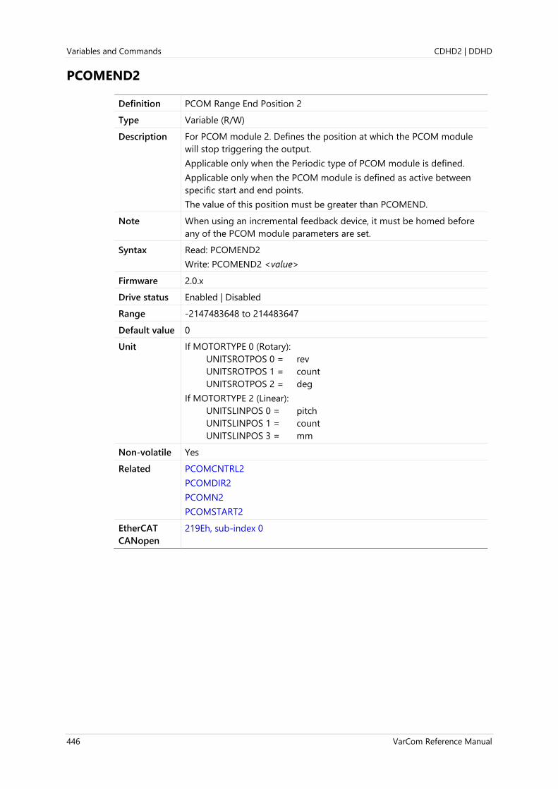
Variables and Commands CDHD2 | DDHD
446 VarCom Reference Manual
PCOMEND2
Definition PCOM Range End Position 2
Type Variable (R/W)
Description For PCOM module 2. Defines the position at which the PCOM module
will stop triggering the output.
Applicable only when the Periodic type of PCOM module is defined.
Applicable only when the PCOM module is defined as active between
specific start and end points.
The value of this position must be greater than PCOMEND.
Note When using an incremental feedback device, it must be homed before
any of the PCOM module parameters are set.
Syntax Read: PCOMEND2
Write: PCOMEND2 <value>
Firmware 2.0.x
Drive status Enabled | Disabled
Range -2147483648 to 214483647
Default value 0
Unit If MOTORTYPE 0 (Rotary):
UNITSROTPOS 0 = rev
UNITSROTPOS 1 = count
UNITSROTPOS 2 = deg
If MOTORTYPE 2 (Linear):
UNITSLINPOS 0 = pitch
UNITSLINPOS 1 = count
UNITSLINPOS 3 = mm
Non-volatile Yes
Related PCOMCNTRL2
PCOMDIR2
PCOMN2
PCOMSTART2
EtherCAT
CANopen
219Eh, sub-index 0

CDHD2 | DDHD Variables and Commands
VarCom Reference Manual 447
PCOMN1
Definition PCOM Periodic Interval 1
Type Variable (R/W)
Description For PCOM module 1. Defines a fixed number (interval) of feedback
counts between each output trigger position.
Applicable only when the Periodic type of PCOM module is defined.
The PCOM module continuously compares the actual position with the
value defined in PCOMN. Whenever the encoder counter is equivalent
to PCOMN, the PCOM module triggers the output.
Applicable only when the PCOM module is defined as active between
specific start and end points.
Note When using an incremental feedback device, it must be homed before
any of the PCOM module parameters are set.
Syntax Read: PCOMN1
Write: PCOMN1<value>
Firmware 2.0.x
Drive status Enabled | Disabled
Range 0 to 214483647
Default value 0
Unit If MOTORTYPE 0 (Rotary):
UNITSROTPOS 0 = rev
UNITSROTPOS 1 = count
UNITSROTPOS 2 = deg
If MOTORTYPE 2 (Linear):
UNITSLINPOS 0 = pitch
UNITSLINPOS 1 = count
UNITSLINPOS 3 = mm
Non-volatile Yes
Related PCOMCNTRL1
PCOMDIR1
PCOMEND1
PCOMSTART1
EtherCAT
CANopen
219Fh, sub-index 0

Variables and Commands CDHD2 | DDHD
448 VarCom Reference Manual

CDHD2 | DDHD Variables and Commands
VarCom Reference Manual 449
PCOMN2
Definition PCOM Periodic Interval 2
Type Variable (R/W)
Description For PCOM module 2. Defines a fixed number (interval) of feedback
counts between each output trigger.
Applicable only when the Periodic type of PCOM module is defined.
The PCOM module continuously compares the actual position with the
value defined in PCOMN. Whenever the encoder counter is equivalent
to PCOMN, the PCOM module triggers the output.
Applicable only when the PCOM module is defined as active between
specific start and end points.
Note When using an incremental feedback device, it must be homed before
any of the PCOM module parameters are set.
Syntax Read: PCOMN2
Write: PCOMN2<value>
Firmware 2.0.x
Drive status Enabled | Disabled
Range 0 to 214483647
Default value 0
Unit If MOTORTYPE 0 (Rotary):
UNITSROTPOS 0 = rev
UNITSROTPOS 1 = count
UNITSROTPOS 2 = deg
If MOTORTYPE 2 (Linear):
UNITSLINPOS 0 = pitch
UNITSLINPOS 1 = count
UNITSLINPOS 3 = mm
Non-volatile Yes
Related PCOMCNTRL2
PCOMDIR2
PCOMEND2
PCOMSTART2
EtherCAT
CANopen
21A0h, sub-index 0

Variables and Commands CDHD2 | DDHD
450 VarCom Reference Manual
PCOMSTART1
Definition PCOM Range Start Position 1
Type Variable (R/W)
Description For PCOM module 1. Defines the position at which the PCOM module
will begin triggering the output.
Applicable only when the Periodic type of PCOM module is defined.
Applicable only when the PCOM module is defined as active between
specific start and end points.
The value of this position must be less than PCOMEND.
Note When using an incremental feedback device, it must be homed before
any of the PCOM module parameters are set.
Syntax Read: PCOMSTART1
Write: PCOMSTART1<value>
Firmware 2.0.x
Drive status Enabled | Disabled
Range -2147483648 to 214483647
Default value 0
Unit If MOTORTYPE 0 (Rotary):
UNITSROTPOS 0 = rev
UNITSROTPOS 1 = count
UNITSROTPOS 2 = deg
If MOTORTYPE 2 (Linear):
UNITSLINPOS 0 = pitch
UNITSLINPOS 1 = count
UNITSLINPOS 3 = mm
Non-volatile Yes
Related PCOMCNTRL1
PCOMDIR1
PCOMEND1
PCOMN1
EtherCAT
CANopen
219Bh, sub-index 0

CDHD2 | DDHD Variables and Commands
VarCom Reference Manual 451
PCOMSTART2
Definition PCOM Range Start Position 2
Type Variable (R/W)
Description For PCOM module 2. Defines the position at which the PCOM module
will begin triggering the output.
Applicable only when the Periodic type of PCOM module is defined.
Applicable only when the PCOM module is defined as active between
specific start and end points.
The value of this position must be less than PCOMEND.
Note When using an incremental feedback device, it must be homed before
any of the PCOM module parameters are set.
Syntax Read: PCOMSTART2
Write: PCOMSTART2<value>
Firmware 2.0.x
Drive status Enabled | Disabled
Range -2147483648 to 214483647
Default value 0
Unit If MOTORTYPE 0 (Rotary):
UNITSROTPOS 0 = rev
UNITSROTPOS 1 = count
UNITSROTPOS 2 = deg
If MOTORTYPE 2 (Linear):
UNITSLINPOS 0 = pitch
UNITSLINPOS 1 = count
UNITSLINPOS 3 = mm
Non-volatile Yes
Related PCOMCNTRL2
PCOMDIR2
PCOMEND2
PCOMN2
EtherCAT
CANopen
219Ch, sub-index 0
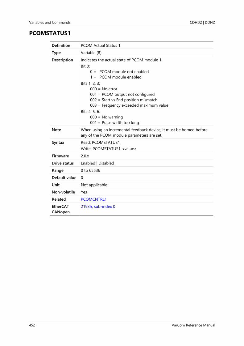
Variables and Commands CDHD2 | DDHD
452 VarCom Reference Manual
PCOMSTATUS1
Definition PCOM Actual Status 1
Type Variable (R)
Description Indicates the actual state of PCOM module 1.
Bit 0:
0 = PCOM module not enabled
1 = PCOM module enabled
Bits 1, 2, 3:
000 = No error
001 = PCOM output not configured
002 = Start vs End position mismatch
003 = Frequency exceeded maximum value
Bits 4, 5, 6:
000 = No warning
001 = Pulse width too long
Note When using an incremental feedback device, it must be homed before
any of the PCOM module parameters are set.
Syntax Read: PCOMSTATUS1
Write: PCOMSTATUS1 <value>
Firmware 2.0.x
Drive status Enabled | Disabled
Range 0 to 65536
Default value 0
Unit Not applicable
Non-volatile Yes
Related PCOMCNTRL1
EtherCAT
CANopen
2193h, sub-index 0

CDHD2 | DDHD Variables and Commands
VarCom Reference Manual 453
PCOMSTATUS2
Definition PCOM Actual Status 2
Type Variable (R)
Description Indicates the actual state of PCOM module 2.
Bit 0:
0 = PCOM module not enabled
1 = PCOM module enabled
Bits 1, 2, 3:
000 = No error
001 = PCOM output not configured
002 = Start vs End position mismatch
003 = Frequency exceeded maximum value
Bits 4, 5, 6:
000 = No warning
001 = Pulse width too long
Note When using an incremental feedback device, it must be homed before
any of the PCOM module parameters are set.
Syntax Read: PCOMSTATUS2
Write: PCOMSTATUS2 <value>
Firmware 2.0.x
Drive status Enabled | Disabled
Range 0 to 65536
Default value 0
Unit Not applicable
Non-volatile Yes
Related PCOMCNTRL2
EtherCAT
CANopen
2194h, sub-index 0

Variables and Commands CDHD2 | DDHD
454 VarCom Reference Manual
PCOMTABLE1
Definition PCOM Table Position 1
Type Variable (R/W)
Description For PCOM module 1. Defines a set of positions at which the output will
be triggered.
Applicable only when the Position Table type of PCOM module is
defined.
The number of trigger positions in the table is defined by
PCOMTABLELEN.
Note When using an incremental feedback device, it must be homed before
any of the PCOM module parameters are set.
Syntax Read: PCOMTABLE1 <index>
Write: PCOMTABLE1 <index> <value>
Firmware 2.0.x
Drive status Enabled | Disabled
Range index: 0 to 31
value: -2147483648 to 214483647
Default value value: 0
Unit If MOTORTYPE 0 (Rotary):
UNITSROTPOS 0 = rev
UNITSROTPOS 1 = count
UNITSROTPOS 2 = deg
If MOTORTYPE 2 (Linear):
UNITSLINPOS 0 = pitch
UNITSLINPOS 1 = count
UNITSLINPOS 3 = mm
Non-volatile Yes
Related PCOMCNTRL1
PCOMTABLELEN1
EtherCAT
CANopen
21A1h, sub-index 0

CDHD2 | DDHD Variables and Commands
VarCom Reference Manual 455

Variables and Commands CDHD2 | DDHD
456 VarCom Reference Manual
PCOMTABLE2
Definition PCOM Table Position 2
Type Variable (R/W)
Description For PCOM module 2. Defines a set of positions at which the output will
be triggered.
Applicable only when the Position Table type of PCOM module is
defined.
The number of trigger positions in the table is defined by
PCOMTABLELEN.
Note When using an incremental feedback device, it must be homed before
any of the PCOM module parameters are set.
Syntax Read: PCOMTABLE2 <index>
Write: PCOMTABLE2 <index> <value>
Firmware 2.0.x
Drive status Enabled | Disabled
Range index: 0 to 31
value: -2147483648 to 214483647
Default value value: 0
Unit If MOTORTYPE 0 (Rotary):
UNITSROTPOS 0 = rev
UNITSROTPOS 1 = count
UNITSROTPOS 2 = deg
If MOTORTYPE 2 (Linear):
UNITSLINPOS 0 = pitch
UNITSLINPOS 1 = count
UNITSLINPOS 3 = mm
Non-volatile Yes
Related PCOMCNTRL2
PCOMTABLELEN2
EtherCAT
CANopen
21A2h, sub-index 0

CDHD2 | DDHD Variables and Commands
VarCom Reference Manual 457
PCOMTABLELEN1
Definition PCOM Table Length 1
Type Variable (R/W)
Description For PCOM module 1. Defines the number of positions in the PCOM
table.
Applicable only when the Position Table type of PCOM module is
defined.
Note When using an incremental feedback device, it must be homed before
any of the PCOM module parameters are set.
Syntax Read: PCOMTABLELEN1
Write: PCOMTABLELEN1 <table_length>
Firmware 2.0.x
Drive status Enabled | Disabled
Range table_length = 1 to 32
Default value 0
Unit If MOTORTYPE 0 (Rotary):
UNITSROTPOS 0 = rev
UNITSROTPOS 1 = count
UNITSROTPOS 2 = deg
If MOTORTYPE 2 (Linear):
UNITSLINPOS 0 = pitch
UNITSLINPOS 1 = count
UNITSLINPOS 3 = mm
Non-volatile Yes
Related PCOMCNTRL1
PCOMTABLE1
EtherCAT
CANopen
2197h, sub-index 0

Variables and Commands CDHD2 | DDHD
458 VarCom Reference Manual
PCOMTABLELEN2
Definition PCOM Table Length 2
Type Variable (R/W)
Description For PCOM module 2. Defines the number of positions in the PCOM
table.
Applicable only when the Position Table type of PCOM module is
defined.
Note When using an incremental feedback device, it must be homed before
any of the PCOM module parameters are set.
Syntax Read: PCOMTABLELEN2
Write: PCOMTABLELEN2 <table_length>
Firmware 2.0.x
Drive status Enabled | Disabled
Range table_length = 1 to 32
Default value 0
Unit If MOTORTYPE 0 (Rotary):
UNITSROTPOS 0 = rev
UNITSROTPOS 1 = count
UNITSROTPOS 2 = deg
If MOTORTYPE 2 (Linear):
UNITSLINPOS 0 = pitch
UNITSLINPOS 1 = count
UNITSLINPOS 3 = mm
Non-volatile Yes
Related PCOMCNTRL2
PCOMTABLE2
EtherCAT
CANopen
2198h, sub-index 0

CDHD2 | DDHD Variables and Commands
VarCom Reference Manual 459
PCOMWIDTH1
Definition PCOM Output Pulse Width 1
Type Variable (R/W)
Description For PCOM module 1. Defines the pulse width of the output signal.
Applicable only when Pulse output type is defined.
Note When using an incremental feedback device, it must be homed before
any of the PCOM module parameters are set.
Syntax Read: PCOMWIDTH1
Write: PCOMWIDTH1 <value>
Firmware 2.0.x
Drive status Enabled | Disabled
Range 0 to 10,000,000 (= 0 to 100 ms)
Default value 100
Unit 0.1 µs
Non-volatile Yes
Related PCOMCNTRL1
EtherCAT
CANopen
2199h, sub-index 0
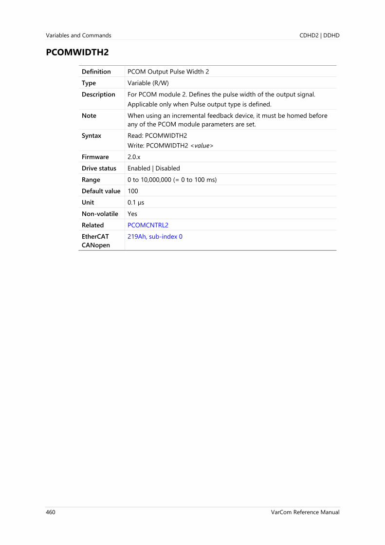
Variables and Commands CDHD2 | DDHD
460 VarCom Reference Manual
PCOMWIDTH2
Definition PCOM Output Pulse Width 2
Type Variable (R/W)
Description For PCOM module 2. Defines the pulse width of the output signal.
Applicable only when Pulse output type is defined.
Note When using an incremental feedback device, it must be homed before
any of the PCOM module parameters are set.
Syntax Read: PCOMWIDTH2
Write: PCOMWIDTH2 <value>
Firmware 2.0.x
Drive status Enabled | Disabled
Range 0 to 10,000,000 (= 0 to 100 ms)
Default value 100
Unit 0.1 µs
Non-volatile Yes
Related PCOMCNTRL2
EtherCAT
CANopen
219Ah, sub-index 0

CDHD2 | DDHD Variables and Commands
VarCom Reference Manual 461
PDEN
Definition Feed Constant (Unit Conversion) Denominator
Type Variable (R/W)
Description The feed constant is the positional movement for any motor movement
and is calculated as the following:
Feed constant = Feed ÷ Driving shaft revolutions
PDEN defines the denominator (revolutions) of the ratio.
Used for scaling the motor revolution (rotary motors) or the motor pitch
(linear motors), according to the type of motor (MOTORTYPE).
Syntax Read: PDEN
Write: PDEN <value>
Firmware 1.2.12
Drive status Enabled | Disabled
Range 1 to 4294967295
Default value 1
Unit Not applicable
Non-volatile Yes
Related PCMD
PNUM
EtherCAT
CANopen
6092h, sub-index 2
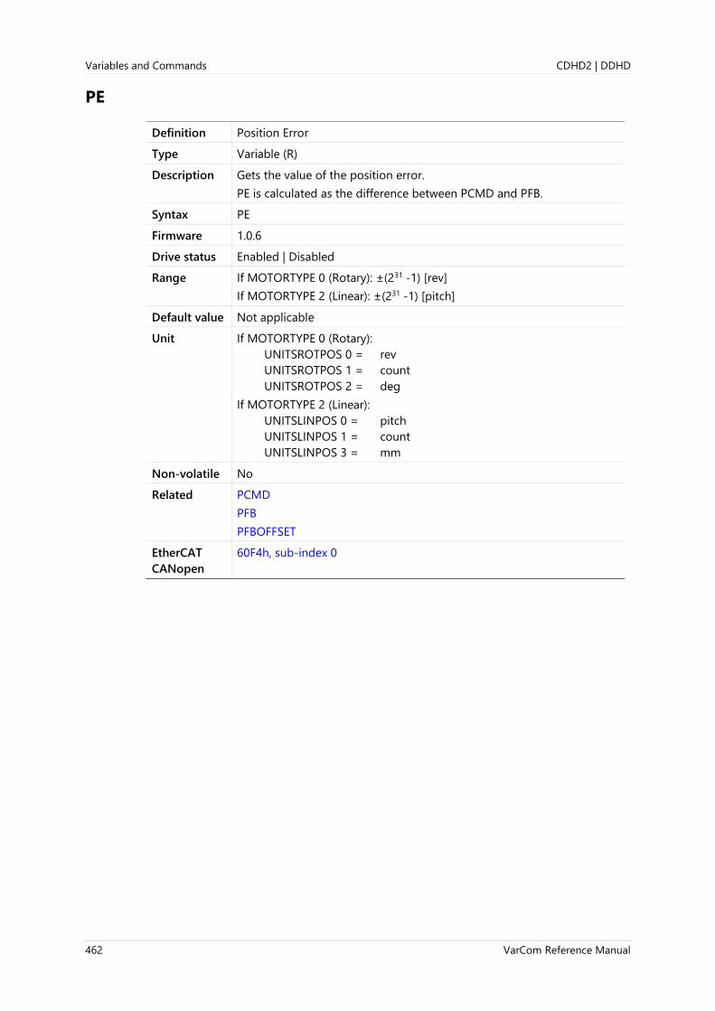
Variables and Commands CDHD2 | DDHD
462 VarCom Reference Manual
PE
Definition Position Error
Type Variable (R)
Description Gets the value of the position error.
PE is calculated as the difference between PCMD and PFB.
Syntax PE
Firmware 1.0.6
Drive status Enabled | Disabled
Range If MOTORTYPE 0 (Rotary): ±(231 -1) [rev]
If MOTORTYPE 2 (Linear): ±(231 -1) [pitch]
Default value Not applicable
Unit If MOTORTYPE 0 (Rotary):
UNITSROTPOS 0 = rev
UNITSROTPOS 1 = count
UNITSROTPOS 2 = deg
If MOTORTYPE 2 (Linear):
UNITSLINPOS 0 = pitch
UNITSLINPOS 1 = count
UNITSLINPOS 3 = mm
Non-volatile No
Related PCMD
PFB
PFBOFFSET
EtherCAT
CANopen
60F4h, sub-index 0

CDHD2 | DDHD Variables and Commands
VarCom Reference Manual 463
PEDELAYED
Definition Delayed Position Error
Type Variable (R)
Description This parameter shows the delayed position error.
PE is calculated as the difference between PCMD and PFB.
PCMD can be delayed by 0 to 31 ms, as defined by PEDELAYTIME.
PEDELAYED is calculated as the difference between the delayed PCMD
and PFB according to the formula:
PEDELAYED(t) = PCMD(t-PEDELAYTIME)-PFB(t)
This is intended to support tuning that aims at non-zero tracking delay.
PEDELAYED is applicable for the linear position controller.
When using full velocity feedforward (KPVFR=1), the position following
error at constant speed is zero. However, it also injects jerks that might
cause vibrations. Jerks and vibrations can be mitigated by reducing the
velocity feedforward. Reduced velocity feedforward causes position
following error, which is proportional to the velocity, according to the
following formula:
PE = V × Tdelay
Where:
Tdelay = (1 – KPVFR) ÷ KPP
When PEDELAYTIME is set to Tdelay, PEDELAYED shows the position
following error without the following error that is due to the reduced
velocity feedforward.
Syntax PEDELAYED
Firmware 2.0.x
Drive status Enabled | Disabled
Range If MOTORTYPE 0 (Rotary): ±(231 -1) [rev]
If MOTORTYPE 2 (Linear): ±(231 -1) [pitch]
Default value Not applicable
Unit If MOTORTYPE 0 (Rotary):
UNITSROTPOS 0 = rev
UNITSROTPOS 1 = count
UNITSROTPOS 2 = deg
If MOTORTYPE 2 (Linear):
UNITSLINPOS 0 = pitch
UNITSLINPOS 1 = count
UNITSLINPOS 3 = mm
Non-volatile No
Related KPVFR
PEDELAYTIME
EtherCAT
CANopen
218Dh, sub-index 0

Variables and Commands CDHD2 | DDHD
464 VarCom Reference Manual
PEDELAYTIME
Definition Delay for Delayed Position Error
Type Variable (R/W)
Description Defines the delay time for PCMD that will be used for calculating
PEDELAYED.
Syntax Read: PEDELAYTIME
Write: PEDELAYTIME <value>
Firmware 2.0.x
Drive status Enabled | Disabled
Range 0 to 31
Default value 0
Unit ms
Non-volatile Yes
Related PEDELAYED
EtherCAT
CANopen
218Eh, sub-index 0

CDHD2 | DDHD Variables and Commands
VarCom Reference Manual 465
PEINPOS
Definition In Position Error Tolerance
Type Variable (R/W)
Description Gets/sets the error tolerance for declaring an “in position” state.
The motor is considered settled when PE has remained below PEINPOS
for a time defined by PEINPOSTIME.
Syntax Read: PEINPOS
Write: PEINPOS <value>
Firmware 1.0.6
Drive status Enabled | Disabled
Range If MOTORTYPE 0 (Rotary): 0 to (231 -1) [rev]
If MOTORTYPE 2 (Linear): 0 to (231 -1) [pitch]
Default value 0.25 [rev]
Unit If MOTORTYPE 0 (Rotary):
UNITSROTPOS 0 = rev
UNITSROTPOS 1 = count
UNITSROTPOS 2 = deg
If MOTORTYPE 2 (Linear):
UNITSLINPOS 0 = pitch
UNITSLINPOS 1 = count
UNITSLINPOS 3 = mm
Non-volatile Yes
Related INPOS
MOVEINC
PEINPOSTIME
PEMAX
STOPPED
EtherCAT
CANopen
6067h, sub-index 0

Variables and Commands CDHD2 | DDHD
466 VarCom Reference Manual
PEINPOSTIME
Definition In Position Time
Type Variable (R/W)
Description PEINPOSTIME specifies the duration of INPOS=1 at the end of a
commanded movement that results in STOPPED=2 (“Profile completed
and drive is in position”).
Syntax Read: PEINPOSTIME
Write: PEINPOSTIME <value>
Firmware 1.0.6
Drive status Enabled | Disabled
Range 0 to 1000
Default value 1
Unit ms
Non-volatile Yes
Related INPOS
MOVEABS
MOVEINC
PE
PEINPOS
STOPPED
EtherCAT
CANopen
6068h, sub-index 0

CDHD2 | DDHD Variables and Commands
VarCom Reference Manual 467
PELOOP
Definition Position Loop Position Error
Type Variable (R)
Description Position error value used by the position loop
Syntax PELOOP
Firmware 1.2.12
Drive status Enabled | Disabled
Range If MOTORTYPE 0 (Rotary): ±(231 -1) [rev]
If MOTORTYPE 2 (Linear): ±(231 -1) [pitch]
Default value Not applicable
Unit If MOTORTYPE 0 (Rotary):
UNITSROTPOS 0 = rev
UNITSROTPOS 1 = count
UNITSROTPOS 2 = deg
If MOTORTYPE 2 (Linear):
UNITSLINPOS 0 = pitch
UNITSLINPOS 1 = count
UNITSLINPOS 3 = mm
Non-volatile No
Related PE
EtherCAT
CANopen
20A3h, sub-index 0
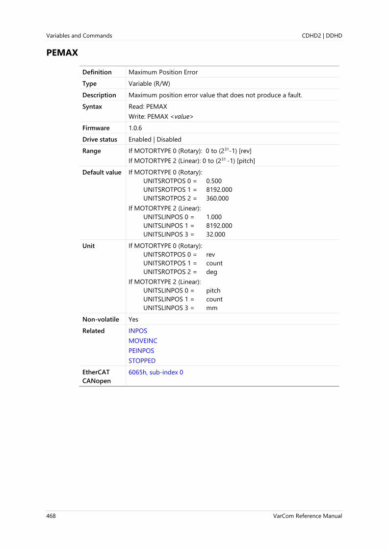
Variables and Commands CDHD2 | DDHD
468 VarCom Reference Manual
PEMAX
Definition Maximum Position Error
Type Variable (R/W)
Description Maximum position error value that does not produce a fault.
Syntax Read: PEMAX
Write: PEMAX <value>
Firmware 1.0.6
Drive status Enabled | Disabled
Range If MOTORTYPE 0 (Rotary): 0 to (231-1) [rev]
If MOTORTYPE 2 (Linear): 0 to (231 -1) [pitch]
Default value If MOTORTYPE 0 (Rotary):
UNITSROTPOS 0 = 0.500
UNITSROTPOS 1 = 8192.000
UNITSROTPOS 2 = 360.000
If MOTORTYPE 2 (Linear):
UNITSLINPOS 0 = 1.000
UNITSLINPOS 1 = 8192.000
UNITSLINPOS 3 = 32.000
Unit If MOTORTYPE 0 (Rotary):
UNITSROTPOS 0 = rev
UNITSROTPOS 1 = count
UNITSROTPOS 2 = deg
If MOTORTYPE 2 (Linear):
UNITSLINPOS 0 = pitch
UNITSLINPOS 1 = count
UNITSLINPOS 3 = mm
Non-volatile Yes
Related INPOS
MOVEINC
PEINPOS
STOPPED
EtherCAT
CANopen
6065h, sub-index 0

CDHD2 | DDHD Variables and Commands
VarCom Reference Manual 469
PFB
Definition Position Feedback
Type Variable (R)
Description PFB is used by the position controller. It is the position value of the
feedback device (motor or load) according to SFBMODE, and includes
any offsets and error corrections that may have been added.
When the system uses a feedback device on motor only, PFB is the
position according to the motor feedback (MFB).
When dual feedback is active, PFB is the position according to the load
feedback (SFB).
When the error correction function is active, PFB shows the value after
correction. Use PFBRAW to view the position value before correction.
Syntax PFB
Firmware 1.0.6
Drive status Enabled | Disabled
Range If MOTORTYPE 0 (Rotary): ±(231 -1) [rev]
If MOTORTYPE 2 (Linear): ±(231 -1) [pitch]
Default value Not applicable
Unit If MOTORTYPE 0 (Rotary):
UNITSROTPOS 0 = rev
UNITSROTPOS 1 = count
UNITSROTPOS 2 = deg
If MOTORTYPE 2 (Linear):
UNITSLINPOS 0 = pitch
UNITSLINPOS 1 = count
UNITSLINPOS 3 = mm
Non-volatile No
Related MFBDIR
PCMD
PE
PFBOFFSET
SFB
SFBMODE
EtherCAT
CANopen
6064h, sub-index 0
Panel d 0 0 0 1 (deg)
d 0 0 0 2 (rev)

Variables and Commands CDHD2 | DDHD
470 VarCom Reference Manual
PFBBACKUP
Definition Position Backup
Type Command
Description Reads the PFB values from non-volatile memory that were saved by the
PFB backup process.
Syntax PFBBACKUP
Firmware 1.3.2
Drive status Enabled | Disabled
Range Not applicable
Default value Not applicable
Unit If MOTORTYPE 0 (Rotary):
UNITSROTPOS 0 = rev
UNITSROTPOS 1 = count
UNITSROTPOS 2 = deg
If MOTORTYPE 2 (Linear):
UNITSLINPOS 0 = pitch
UNITSLINPOS 1 = count
UNITSLINPOS 3 = mm
Non-volatile Not applicable
Related PFB
PFBBACKUPMODE
EtherCAT
CANopen
2088h, sub-index 0

CDHD2 | DDHD Variables and Commands
VarCom Reference Manual 471
PFBBACKUPMODE
Definition Position Backup Mode
Type Variable (R/W)
Description Enables and disables the position (PFB) backup process.
In the event of an emergency stop, the PFB backup process saves PFB to
non-volatile memory, and restores it at the next power up.
Syntax Read: PFBBACKUPMODE
Write: PFBBACKUPMODE<value>
Firmware 1.3.2
Drive status Enabled | Disabled
Range 0 = PFB backup process disabled
1 = PFB backup process enabled
Default value 0
Unit Not applicable
Non-volatile Yes
Related PFB
PFBBACKUP
EtherCAT
CANopen
2089h, sub-index 0

Variables and Commands CDHD2 | DDHD
472 VarCom Reference Manual
PFBOFFSET
Definition Position Offset
Type Variable (R/W)
Description Gets/sets a feedback offset that is added to the internal cumulative
position counter, to give the value of PFB.
When using count units, only integer values can be entered.
Syntax Read: PFBOFFSET
Write: PFBOFFSET <value>
Firmware 1.0.6
Drive status Disabled
Range If MOTORTYPE 0 (Rotary): ±(231 -1) [rev]
If MOTORTYPE 2 (Linear): ±(231 -1) [pitch]
Default value 0
Unit If MOTORTYPE 0 (Rotary):
UNITSROTPOS 0 = rev
UNITSROTPOS 1 = count
UNITSROTPOS 2 = deg
If MOTORTYPE 2 (Linear):
UNITSLINPOS 0 = pitch
UNITSLINPOS 1 = count
UNITSLINPOS 3 = mm
Non-volatile Yes
Related PCMD
PE
PFB
EtherCAT
CANopen
2095h, sub-index 0
Panel P 0 0 2 1
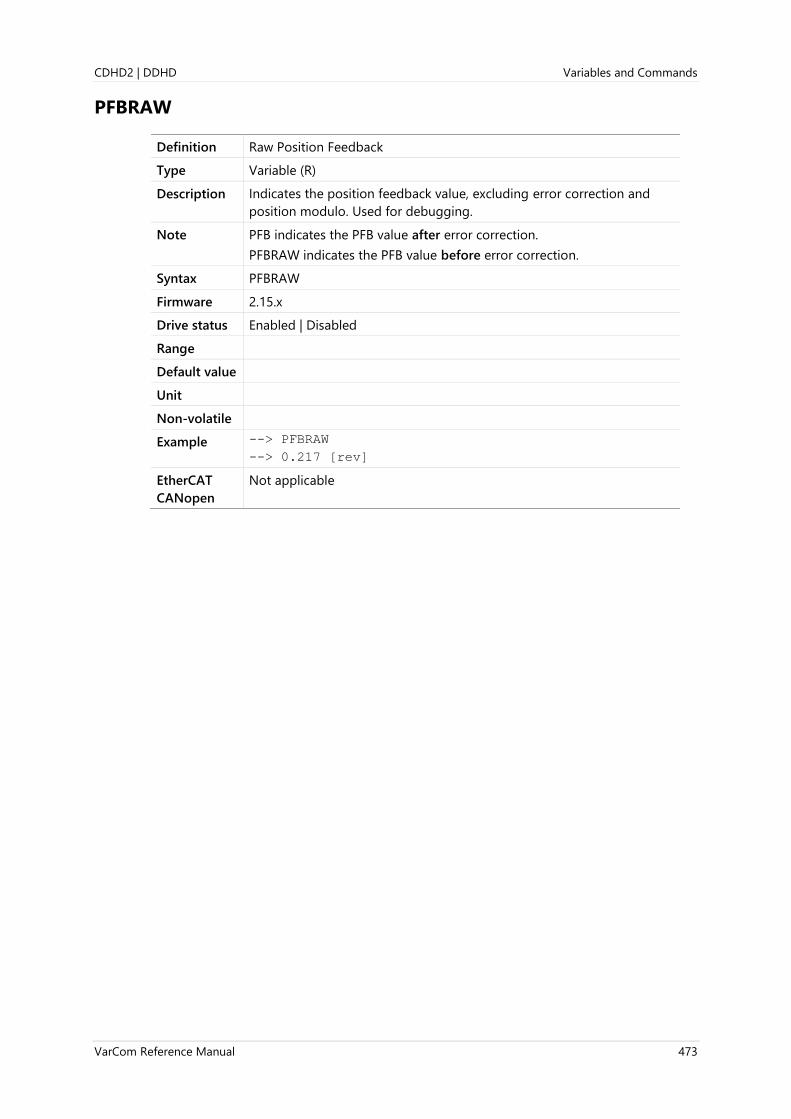
CDHD2 | DDHD Variables and Commands
VarCom Reference Manual 473
PFBRAW
Definition Raw Position Feedback
Type Variable (R)
Description Indicates the position feedback value, excluding error correction and
position modulo. Used for debugging.
Note PFB indicates the PFB value after error correction.
PFBRAW indicates the PFB value before error correction.
Syntax PFBRAW
Firmware 2.15.x
Drive status Enabled | Disabled
Range
Default value
Unit
Non-volatile
Example --> PFBRAW
--> 0.217 [rev]
EtherCAT
CANopen
Not applicable

Variables and Commands CDHD2 | DDHD
474 VarCom Reference Manual
PHASEFIND
Definition Phase Find Command
Type Command
Description Initiates a procedure that initializes commutation for incremental
encoder systems. See PHASEFINDMODE for the execution options.
The PHASEFIND procedure can be used only on a balanced axis; it
cannot be used for unbalanced mechanics, such as a vertical Z-axis. In
addition, the PHASEFIND procedure cannot be performed when gantry
mode is active (GANTRYMODE≠0).
Note Although highly unlikely, it is possible that PHASEFIND will produce an
incorrect commutation angle, resulting in a runaway condition.
Therefore, when using the PHASEFIND procedure, it is strongly
recommended that the commutation error detection mechanism be
enabled by setting appropriate values for COMMERRTTHRESH and
COMMERRVTHRESH.
Syntax PHASEFIND
Firmware 1.0.6
Drive status Disabled
Range Not applicable
Default value Not applicable
Unit Not applicable
Non-volatile Not applicable
Related FEEDBACKTYPE
MENCRES
MENCTYPE
MPHASE
PHASEFINDGAIN
PHASEFINDI
PHASEFINDMODE
PHASEFINDST
ZERO
EtherCAT
CANopen
20A4h, sub-index 0
Panel C 0 0 1 3

CDHD2 | DDHD Variables and Commands
VarCom Reference Manual 475
PHASEFINDANGLE
Definition Forced Electrical Position
Type Variable (R/W)
Description Gets/sets the position in one revolution.
Applicable only for MENCTYPE 11.
Syntax Read: PHASEFINDANGLE
Write: PHASEFINDANGLE <value>
Firmware 1.0.6
Drive status Enabled | Disabled
Range 0 to 65535
Default value 0
Unit 65536/(electrical cycle)
Non-volatile Yes
Related PHASEFIND
PHASEFINDMODE
EtherCAT
CANopen
20A5h, sub-index 0

Variables and Commands CDHD2 | DDHD
476 VarCom Reference Manual
PHASEFINDDELTA
Definition Delta Angle for Phase Find Tuning
Type Variable (R/W)
Description Delta angle for phase find tuning.
Syntax Read: PHASEFINDDELTA
Write: PHASEFINDDELTA <value>
Firmware 1.4.4
Drive status Enabled | Disabled
Range 0 to 359
Default value 5
Unit Electrical degree
Non-volatile No
Related PHASEFINDMODE
EtherCAT
CANopen
Not applicable

CDHD2 | DDHD Variables and Commands
VarCom Reference Manual 477
PHASEFINDGAIN
Definition Phase Find Gain
Type Variable (R/W)
Description Adjusts the gain of the phase finding mechanism.
Syntax Read: PHASEFINDGAIN
Write: PHASEFINDGAIN <value>
Firmware 1.0.6
Drive status Disabled
Range 0.1 to 10
Default value 10.000
Unit Not applicable
Non-volatile Yes
Related PHASEFIND
PHASEFINDMODE
EtherCAT
CANopen
20A6h, sub-index 0
Panel P 2 0 1 4

Variables and Commands CDHD2 | DDHD
478 VarCom Reference Manual
PHASEFINDI
Definition Phase Find Current
Type Variable (R/W) .
Description Adjusts the current of the phase finding mechanism.
Syntax Read: PHASEFINDI
Write: PHASEFINDI <value>
Firmware 1.0.6
Drive status Disabled
Range 0 to IMAX
Default value 0.848
Unit A
Non-volatile Yes
Related PHASEFIND
PHASEFINDMODE
EtherCAT
CANopen
20A7h, sub-index 0
Panel P 2 0 1 2

CDHD2 | DDHD Variables and Commands
VarCom Reference Manual 479
PHASEFINDMODE
Definition Phase Find Mode
Type Variable (R/W)
Description Gets/sets the commutation Phase Find mode.
Note Although highly unlikely, it is possible that PHASEFIND will produce an
incorrect commutation angle, resulting in a commutation error
(runaway motor) condition. Therefore, when using the PHASEFIND
procedure, it is strongly recommended that the commutation error
detection mechanism be enabled by setting appropriate values for
COMMERRTTHRESH and COMMERRVTHRESH.
Syntax Read: PHASEFINDMODE
Write: PHASEFINDMODE <value>
Firmware 1.0.6
Drive status Disabled
Range PHASEFINDMODE 2 [Soft start]. Default.
Also referred to as a Wake-No-Shake routine.
Sets current command and searches for angle at which no movement
occurs, and then adds 90 degrees to this angle.
Uses PI controller where velocity is an input and commutation angle is
an output.
Note: The angle found may cause movement in the wrong direction;
therefore, the process is performed twice to avoid incorrect
detection.
Use this mode with motors that have non-limited motion.
1. Set PHASEFINDI - range (0 to IMAX) [A peak]. If value is 0, drive will
overwrite it to 0.15MIN(DICONT,MICONT).
A high value provides a more exact result but causes a higher rotor
jump at start of process.
2. Set PHASEFINDGAIN - range (0.1 to 10). Use a lower value for
systems with high inertia, and vice versa.
3. Set PHASEFINDTIME - range (0 to 16000) [ms]. Use a higher value
for systems with high inertia, and vice versa.
4. Type PHASEFIND, and then EN.

Variables and Commands CDHD2 | DDHD
480 VarCom Reference Manual
PHASEFINDMODE 4 [Smooth start]
Sets commutation angle to 180 degrees and increases current until a
movement of 1 electrical angle is detected.
Divides the angle by half and sets the appropriate sign to move in the
opposite direction. Increases current until a movement of 1 electrical
angle is detected. Repeats until no movement occurs at maximum
current. Adds 90 degree to the found angle.
The maximum current value used during the process is limited by
MICONT.
Use this mode with motors that have non-limited motion.
1. Set PHASEFINDGAIN — range (0.1 - 10). In this mode the parameter
is used as a factor for total movement. The larger factor will provide
less movement but will take more time to execute PHASEFIND
process. In systems with low inertia and cogging the actual
movement will be unpredictable but never more than 90 electrical
degrees. Use a higher value for systems with high inertia, and vice
versa.
2. Type PHASEFIND, and then EN.
PHASEFINDMODE 5 [High torque start]
Sets commutation angle to 180 degrees and increases current until a
movement of 1 electrical angle is detected.
Divides the angle by half and sets the appropriate sign to move in the
opposite direction. Increases current until a movement of 1 electrical
angle is detected. Repeats until no movement occurs at maximum
current. Adds 90 degree to the found angle.
The maximum current value used during the process is limited by IMAX.
Use this mode with motors that have non-limited motion.
Use this mode when a high torque is required for initial motion.
1. Set PHASEFINDGAIN — range (0.1 - 10). In this mode the parameter
is used as a factor for total movement. The larger factor will provide
less movement but will take more time to execute PHASEFIND
process. In systems with low inertia and cogging the actual
movement will be unpredictable but never more than 90 electrical
degrees. Use a higher value for systems with high inertia, and vice
versa.
2. Type PHASEFIND, and then EN.
PHASEFINDMODE 11 [Manual commutation]
Commutation is defined by the value of PHASEFINDANGLE.
1. Set PHASEFINDANGLE — range (0 to 65535), where 1 electrical
angle is 65535/359.
2. Type PHASEFIND, and then EN.
3. Use this mode if the angle is known. For example:
1. Set shaft to zero electrical degrees (be sure MPHASE = 0). Use the
ZERO command to set the shaft to zero electrical degree placement.
2. Set PHASEFINDANGLE = 0
3. Type PHASEFIND, and then EN

CDHD2 | DDHD Variables and Commands
VarCom Reference Manual 481
PHASEFINDMODE 12 [Zeroing]
Applies the ZERO command and uses the resulting MPHASE. Supports
systems with Z-axis.
Utilizes the following parameters:
PHASEFINDI – Current applied to phases, in amperes. Minimum is 0;
maximum is IMAX; default is 0.1MICONT. A higher current will
provide a more exact result, but will cause more aggressive
behavior during the PHASEFIND process. Current value should be
high enough to hold the load of the Z-axis.
PHASEFINDDELTA – Allowable movement before PHASEFIND starts, in
electrical degrees. Minimum is 0; maximum is 359; default is 5.
PHASEFINDTIME – Timeout time, in milliseconds. Minimum is
30 seconds; maximum is 60 seconds; default is 30 seconds. Can be
modified by user in the event of a timeout fault. For example, if
PHASEFINDI is high and motor has a load, rotor oscillations during
PHASEFIND may require more than 30 seconds for settling.
WNSERR – Faults. For example:
“Not enough motion detected”. Possibly due to hard stop, low
PHASEFINDI, locked rotor, high load.
“Motor Settling Timeout”. Due to rotor oscillations during
PHASEFIND process. Try increasing PHASEFINDTIME. Verify
PEINPOS is not 0 (this parameter is used to define settling status).
PEINPOS– A lower value will provide a more exact result.
Type PHASEFIND, and then EN.
Wait for movement greater than n electrical degrees, where n is defined
by PHASEFINDDELTA.
If no movement is detected within 1 second, then start the phasing
process.
Apply ZERO command and use the resulting MPHASE.
Default value 2
Unit Not applicable
Non-volatile Yes
Related FEEDBACKTYPE
MENCTYPE
MPHASE
PHASEFIND (Modes 0, 2, 4, 11)
PHASEFINDANGLE (Mode 11)
PHASEFINDI (Mode 2)
PHASEFINDGAIN (Modes 2, 4)
PHASEFINDST (Modes 0, 2, 4,11)
PHASEFINDTIME (Mode 2)
WNSERR (Modes 2,4)
ZERO
EtherCAT
CANopen
20A8h, sub-index 0
Panel P 2 0 1 1

Variables and Commands CDHD2 | DDHD
482 VarCom Reference Manual
PHASEFINDST
Definition Phase Find Status
Type Variable (R)
Description Indicates the state of the commutation Phase Find procedure for
incremental encoders.
Syntax PHASEFINDST
Firmware 1.0.6
Drive status Disabled
Range 0 = Not started
1 = Running
2 = Succeeded
3 = Failed
Default value Not applicable
Unit Not applicable
Non-volatile No
Related FEEDBACKTYPE
MENCTYPE
PHASEFIND
PHASEFINDMODE
ZERO
EtherCAT
CANopen
20A9h, sub-index 0

CDHD2 | DDHD Variables and Commands
VarCom Reference Manual 483
PHASEFINDTIME
Definition Phase Find Duration
Type Variable (R/W)
Description Gets/set the duration of the phase finding mechanism in a soft start
(PHASEFINDMODE 2).
Syntax Read: PHASEFINDTIME
Write: PHASEFINDTIME <value>
Firmware 1.0.6
Drive status Disabled
Range 0 to 60000
Default value 100
Unit ms
Non-volatile Yes
Related PHASEFIND
PHASEFINDMODE
EtherCAT
CANopen
20AAh, sub-index 0
Panel P 2 0 1 3

Variables and Commands CDHD2 | DDHD
484 VarCom Reference Manual
PNUM
Definition Feed Constant (Unit Conversion) Numerator
Type Variable (R/W)
Description The feed constant is the positional movement for any motor movement
and is calculated as the following:
Feed constant = Feed ÷ Driving shaft revolutions
PNUM defines the numerator (feed) of the ratio.
Used for scaling the motor revolution (rotary motors) or the motor pitch
(linear motors), according to the type of motor (MOTORTYPE).
Syntax Read: PNUM
Write: PNUM <value>
Firmware 1.2.12
Drive status Enabled | Disabled
Range 1 to 4294967295
Default value 360000
Unit Not applicable
Non-volatile Yes
Related PCMD
PDEN
EtherCAT
CANopen
6092h, sub-index 1
Panel P 6 0 0 4
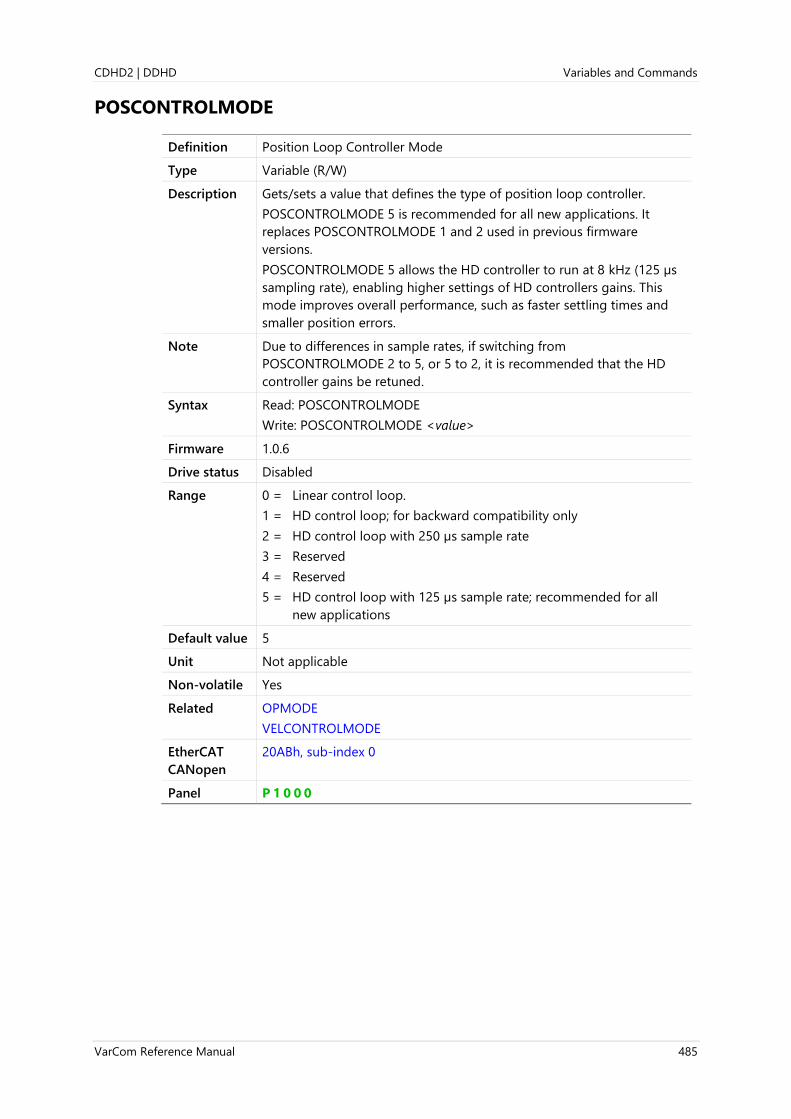
CDHD2 | DDHD Variables and Commands
VarCom Reference Manual 485
POSCONTROLMODE
Definition Position Loop Controller Mode
Type Variable (R/W)
Description Gets/sets a value that defines the type of position loop controller.
POSCONTROLMODE 5 is recommended for all new applications. It
replaces POSCONTROLMODE 1 and 2 used in previous firmware
versions.
POSCONTROLMODE 5 allows the HD controller to run at 8 kHz (125 µs
sampling rate), enabling higher settings of HD controllers gains. This
mode improves overall performance, such as faster settling times and
smaller position errors.
Note Due to differences in sample rates, if switching from
POSCONTROLMODE 2 to 5, or 5 to 2, it is recommended that the HD
controller gains be retuned.
Syntax Read: POSCONTROLMODE
Write: POSCONTROLMODE <value>
Firmware 1.0.6
Drive status Disabled
Range 0 = Linear control loop.
1 = HD control loop; for backward compatibility only
2 = HD control loop with 250 µs sample rate
3 = Reserved
4 = Reserved
5 = HD control loop with 125 µs sample rate; recommended for all
new applications
Default value 5
Unit Not applicable
Non-volatile Yes
Related OPMODE
VELCONTROLMODE
EtherCAT
CANopen
20ABh, sub-index 0
Panel P 1 0 0 0

Variables and Commands CDHD2 | DDHD
486 VarCom Reference Manual
POSLIMHYST
Definition Software Position Limit Switch Hysteresis Value
Type Variable (R/W)
Description Hysteresis value around the software position limit switch.
Serves to prevent false activation of a software limit switch due to an
unstable control loop
Syntax Read: POSLIMHYST
Write: POSLIMHYST <value>
Firmware 1.15.xx
Drive status Disabled
Range 0 to 1/36 (0.278)
Default value 0.003
Unit If MOTORTYPE 0 (Rotary): revolution
If MOTORTYPE 2 (Linear): pitch
Non-volatile Yes
Related POSLIMMODE
EtherCAT
CANopen
214Ah, sub-index 0
Panel P 5 0 0 3

CDHD2 | DDHD Variables and Commands
VarCom Reference Manual 487
POSLIMMODE
Definition Position Limiting Mode
Type Variable (R/W)
Description Defines whether software position limits and/or transient position limits
and/or homing limits are applied.
The value of POSLIMMODE depends on the bit values:
Bit 2 Bit 1 Bit 0 Value
0 0 0 = 0
0 0 1 = 1
0 1 0 = 2
0 1 1 = 3
1 0 0 = 4
1 0 1 = 5
1 1 0 = 6
1 1 1 = 7
Bit 0:
0 = Software position limits disabled
1 = Software position limits enabled
Bit 1:
0 = Transient limits are used for all motion
1 = Transient limits are ignored during any motion
Bit 2:
0 = Transient limits are used for homing
1 = Transient limits are ignored during homing
Software position limits (bit 0) can be set only after a successful homing
has been performed.
If bit 0 = 1, POSLIMNEG and POSLIMPOS serve as motion limits. When
either limit is crossed, a deceleration occurs according to the value of
DECSTOPTIME, unless it exceeds the value of DECSTOP. Once a limit is
crossed, only motion commands in the reverse direction can be
executed.
When a software limit switch is engaged, the 7-segment LED display
shows either L4 or L5. If both switches are engaged, the display shows
L6.
Software position limits and the Disable mode use the same
deceleration settings.

Variables and Commands CDHD2 | DDHD
488 VarCom Reference Manual
If bit 1 = 0, transient limits serve as motion limits. Transient limits are set
when the respective hardware limit input is set; at the same time, the
actual position is captured internally. The transient limits are maintained
until the hardware limit input is reset and the actual position is closer to
the travel range than the captured position above. For example, if a
transient positive limit bit is set, this bit will be reset when the hardware
positive limit input is reset and the actual position is less than the
position that was captured when the positive hardware limit input was
originally set.
The drive will respond to the presence of a transient limit bit as if the
respective hardware limit input is set.
Syntax Read: POSLIMMODE
Write: POSLIMMODE <value>
Firmware 1.2.12; 1.40.0
Drive status Enabled | Disabled
Range 0 to 7
Note: Values 4 and 5 (where bit 1 = 0 and bit 2= 1) should not be used,
since they do not represent any backward compatible configuration.
Default value 6
Unit Not applicable
Non-volatile Yes | No
Related DECSTOP
DECSTOPTIME
POSLIMNEG
POSLIMPOS
LIMSWITCHNEG
LIMSWITCHPOS
EtherCAT
CANopen
20ACh, sub-index 0
Panel P 5 0 0 4

CDHD2 | DDHD Variables and Commands
VarCom Reference Manual 489
L1 = Hardware negative limit switch is open
L2 = Hardware positive limit switch is open
Motor moves toward limit switch.
Negative limit switch
Limit switch is OFF
POSLIMMODE 0
Positive limit switch
Positive
limit input Off
On
Actual
speed0
X
Limit switch is engaged. Motor decelerates according to DECSTOP value.
Hard stop Hard stop
Drive prevent motion into limit switch input direction. In this case possible problem: Positive limit inactive after motor stopped. Motor can continue moving away from limit switch and crash into hard stop
POSLIMMODE 2Drive capture position of limit switch and allow to motion only to opposite direction , regardless state of limit switch input.
X

Variables and Commands CDHD2 | DDHD
490 VarCom Reference Manual
POSLIMNEG
Definition Software Position Limit Minimum
Type Variable (R/W)
Description The minimum position for software limit.
Syntax Read: POSLIMNEG
Write: POSLIMNEG <value>
Firmware 1.2.12
Drive status Disabled
Range If MOTORTYPE 0 (Rotary): ±(231 -1) [rev]
If MOTORTYPE 2 (Linear): ±(231 -1) [pitch]
Default value 0
Unit If MOTORTYPE 0 (Rotary):
UNITSROTPOS 0 = rev
UNITSROTPOS 1 = count
UNITSROTPOS 2 = deg
If MOTORTYPE 2 (Linear):
UNITSLINPOS 0 = pitch
UNITSLINPOS 1 = count
UNITSLINPOS 3 = mm
Non-volatile Yes
Related POSLIMMODE
POSLIMPOS
EtherCAT
CANopen
607Dh, sub-index 1
Panel P 5 0 0 5
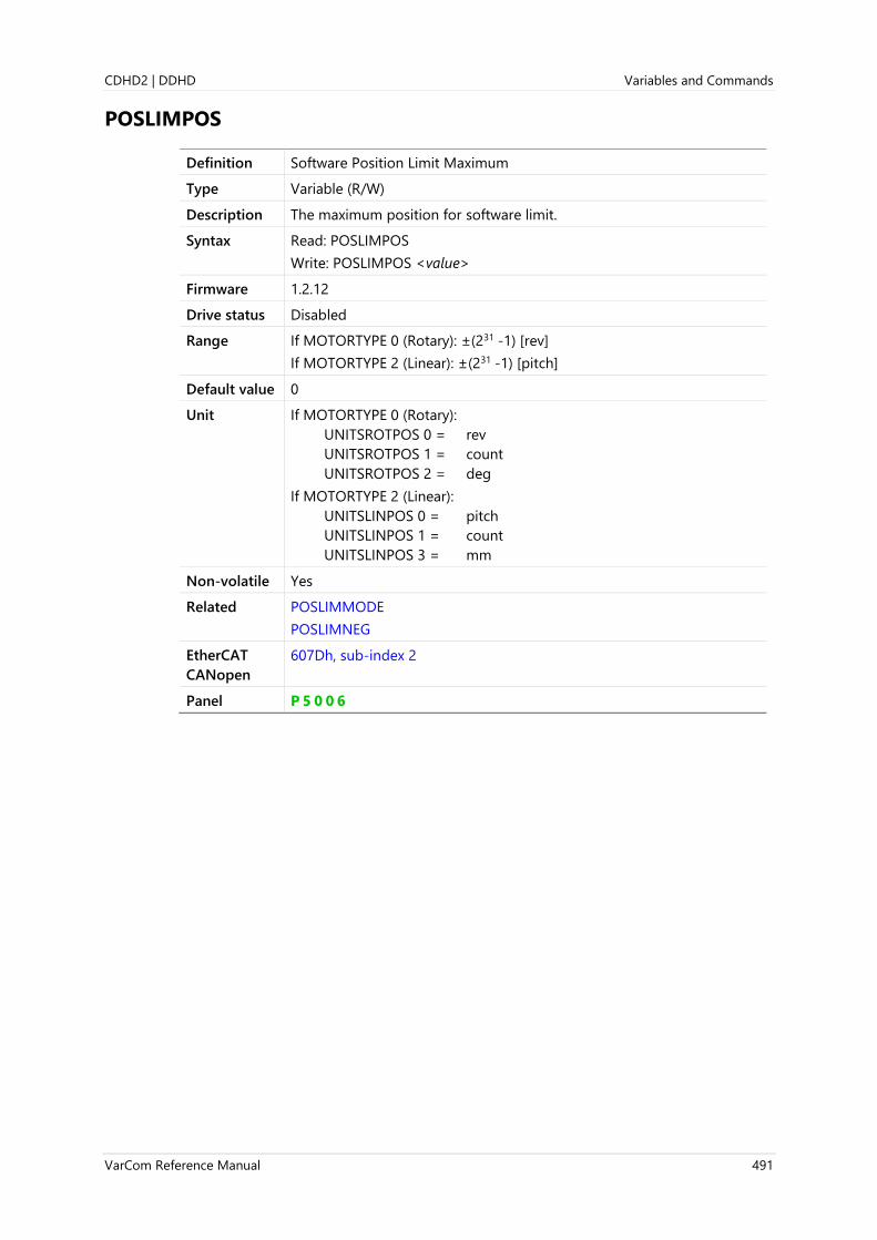
CDHD2 | DDHD Variables and Commands
VarCom Reference Manual 491
POSLIMPOS
Definition Software Position Limit Maximum
Type Variable (R/W)
Description The maximum position for software limit.
Syntax Read: POSLIMPOS
Write: POSLIMPOS <value>
Firmware 1.2.12
Drive status Disabled
Range If MOTORTYPE 0 (Rotary): ±(231 -1) [rev]
If MOTORTYPE 2 (Linear): ±(231 -1) [pitch]
Default value 0
Unit If MOTORTYPE 0 (Rotary):
UNITSROTPOS 0 = rev
UNITSROTPOS 1 = count
UNITSROTPOS 2 = deg
If MOTORTYPE 2 (Linear):
UNITSLINPOS 0 = pitch
UNITSLINPOS 1 = count
UNITSLINPOS 3 = mm
Non-volatile Yes
Related POSLIMMODE
POSLIMNEG
EtherCAT
CANopen
607Dh, sub-index 2
Panel P 5 0 0 6

Variables and Commands CDHD2 | DDHD
492 VarCom Reference Manual
PRBFRQ
Definition PRB Generator Frequency
Type Variable (R/W)
Description Defines the frequency for PRB (pseudo-random binary) excitation.
For pseudo binary noise (PRBPARAM 1), PRBFRQ has no effect.
For sine and square wave generators (PRBPARAM 2, PRBPARAM 3),
PRBFRQ defines the frequency of the sine and square wave generator,
respectively.
Syntax Read: PRBFRQ
Write: PRBFRQ <value>
Firmware 1.0.6
Drive status Enabled | Disabled
Range 0 to 5000
Default value 100.000
Unit Hz
Non-volatile No
Related PRBMODE
PRBPARAM
EtherCAT
CANopen
20ADh, sub-index 0

CDHD2 | DDHD Variables and Commands
VarCom Reference Manual 493
PRBHOLD
Definition PRB Hold Mode
Type Variable (R/W)
Description When PRBHOLD=1 and PRBMODE=1, and RECORD is active, the output
of the linear velocity controller is synchronized to the data recording,
and will be updated when a record sample is taken.
Syntax Read: PRBHOLD
Write: PRBHOLD <value>
Firmware 2.0.x
Drive status Enabled | Disabled
Range 0 = PRB hold mode not active
1 = PRB hold mode active
Default value 0
Unit Not applicable
Non-volatile No
Related PRBMODE
PRBPARAM
RECORD
EtherCAT
CANopen
218Bh, sub-index 0

Variables and Commands CDHD2 | DDHD
494 VarCom Reference Manual
PRBICMD
Definition PRB Current Command
Type Variable (R)
Description This parameter shows the PRB injection to ICMD.
This parameter is recordable.
Syntax PRBICMD
Firmware 2.0.x
Drive status Enabled | Disabled
Range 0 to ILIM
Default value Not applicable
Unit A
Non-volatile No
Related PRBMODE
PRBPARAM
EtherCAT
CANopen
218Ah, sub-index 0

CDHD2 | DDHD Variables and Commands
VarCom Reference Manual 495
PRBMODE
Definition PRB Activation Mode
Type Variable (R/W)
Description Get/sets the activation mode of the PRB signal generator. PRB can
either be disabled (PRBMODE 0), continuously activated (PRBMODE 2),
or activated only when recording has been triggered (PRBMODE 1).
PRBMODE is set to 0 at the end of recording to prevent unintended
activation of PRB generator upon the next recording.
Syntax Read: PRBMODE
Write: PRBMODE <value>
Firmware 1.0.6
Drive status Enabled | Disabled
Range 0 = PRB generator not activated
1 = PRB generator activated only during recording
2 = PRB generator activated continuously
Default value 0
Unit Not applicable
Non-volatile No
Related PRBFRQ
PRBPARAM
RECORD
RECTRIG
EtherCAT
CANopen
20AEh, sub-index 0

Variables and Commands CDHD2 | DDHD
496 VarCom Reference Manual
PRBPARAM
Definition PRB Generator Configuration
Type Command
Description The PRB (pseudo-random binary) generator enables several advanced
tests on the controlled axis. These tests include injecting sine or square
wave signals of specified frequency in addition to the current and
velocity commands. The PRB noise generator is used to excite the
system with a wide uniform spectrum signal for identification purposes.
Syntax PRBPARAM {Signal_type} {Icmd_amp} {Vcmd_amp} {Update_ratio}
Firmware 1.0.6
Drive status Enabled | Disabled
Range Signal_type:
0 = Not activated
1 = Pseudo random binary
2 = Sine wave
3 = Square wave
Icmd_amp = torque amplitude in [A].
Vcmd_amp = velocity amplitude in velocity units (as defined by
UNITSROTVEL or UNITSLINVEL)
Update_ratio = update ratio relative to current loop update rate.
Default value Not applicable
Unit Not applicable
Non-volatile Not applicable
Related PRBFRQ
PRBMODE
EtherCAT
CANopen
20AFh, sub-index 1

CDHD2 | DDHD Variables and Commands
VarCom Reference Manual 497
PROBECONFIG
Definition Touch Probe Configuration
Type Command
Description Defines the probe functionality.
Syntax PROBECONFIG <probe number> queries the configuration
PROBECONFIG {<probe number> <enable trigger> <capture method>
<trigger source> <capture edge> <sampled variable>}
Firmware 1.15.xx
Drive status Enabled | Disabled
Range probe number:
1 = First probe
enable trigger:
0 = Disable triggering
1 = Enable triggering
capture method:
0 = Trigger first event (single)
1 = Continuous (repeated)
trigger source:
0 = Digital input
1 = Encoder index
capture edge:
0 = Idle (use before changing edge event configuration and
before reactivating one-shot probing)
1 = Rising edge
2 = Falling edge
sampled variable (H00 to H0F)
Default value Not applicable
Unit Not applicable
Non-volatile No
Example Rejection of the command because probe functionality has not been
assigned to any of the digital inputs.
PROBECONFIG 1 1 0 0 1 H0F
ERR 260 No input assigned to touch probe
Example Configuring probe 1 to capture the values of all specified variables once
a single event of rising edge occurs.
INMODE 2 27
PROBECONFIG 1 1 0 0 1 HF
Example Configuring probe 1 to continuously capture position and velocity at
each falling edge event.
INMODE 2 27
PROBECONFIG 1 1 1 0 2 H05
Example Setting probe 1 to idling to prevent capturing.
PROBECONFIG 1 1 1 0 0 H05
Example Setting probe 1 to idling to prevent capturing.
PROBECONFIG 1 1 1 0 0 H05

Variables and Commands CDHD2 | DDHD
498 VarCom Reference Manual
Example Continuously probing by using the feedback index at rising edge.
PROBECONFIG 1 1 1 1 1 H05
Related PROBECOUNTER
PROBEDATAFALL
PROBEDATARISE
PROBELEVELPRD
PROBESTATUS
EtherCAT
CANopen
Not applicable

CDHD2 | DDHD Variables and Commands
VarCom Reference Manual 499
PROBECOUNTER
Definition Touch Probe Event Counter
Type Variable (R)
Description Returns the number of captured events.
PROBECOUNTER variable is incremented each time a configured event
occurs.
Syntax PROBECOUNTER
Firmware 1.15.xx
Drive status Enabled | Disabled
Range 0 to 65535
Default value 0
Unit Not applicable
Non-volatile No
Example -->PROBECOUNTER
Rise edge events: 0
Fall edge events: 0
Related PROBECONFIG
PROBESTATUS
EtherCAT
CANopen
2131h, sub-index 1

Variables and Commands CDHD2 | DDHD
500 VarCom Reference Manual
PROBEDATAFALL
Definition Touch Probe Sampled Data Falling
Type Command
Description Reads and stores the captured data from the last event on the falling
edge.
Syntax PROBEDATAFALL {1|2}
Firmware 1.15.xx
Drive status Enabled | Disabled
Range 1 = Probe 1
2 = Probe 2
Default value Not applicable
Unit Not applicable
Non-volatile No
Example PROBECONFIG 1 1 0 0 2 h0F
Before edge event:
probedatafall 1
0.000 [Counts] ->position
0.000 [Counts] ->position error
0.000 [rpm] ->velocity
0.000 [A] ->iq
After event occurred:
probedatafall 1
434041.314 [Counts]
0.000 [Counts]
497.667 [rpm]
0.068 [A]
Example PROBECONFIG 1 1 0 0 2 h05
After event occurred:
probedatafall 1
1278100.564 [Counts]
482.546 [rpm]
Related PROBECONFIG
PROBEDATARISE
EtherCAT
CANopen
2148h, sub-index 1

CDHD2 | DDHD Variables and Commands
VarCom Reference Manual 501
PROBEDATARISE
Definition Touch Probe Sampled Data Rising
Type Variable (R)
Description Reads and stores the captured data from the last event on the rising
edge.
Syntax PROBEDATARISE {1|2}
Firmware 1.15.xx
Drive status Enabled | Disabled
Range 1 = Probe 1
2 = Probe 2
Default value Not applicable
Unit Not applicable
Non-volatile No
Example PROBECONFIG 1 1 0 0 1 h0F
Before edge event:
probedatarise 1
0.000 [Counts] ->position
0.000 [Counts] ->position error
0.000 [rpm] ->velocity
0.000 [A] ->iq
After event occurred:
probedatarise 1
434041.314 [Counts]
0.000 [Counts]
497.667 [rpm]
0.068 [A]
Example PROBECONFIG 1 1 0 0 1 h05
After event occurred:
probedatarise 1
434041.314 [Counts] ->position
49497.667 [rpm] ->iq
Related PROBECONFIG
PROBEDATAFALL
EtherCAT
CANopen
2147h, sub-index 1
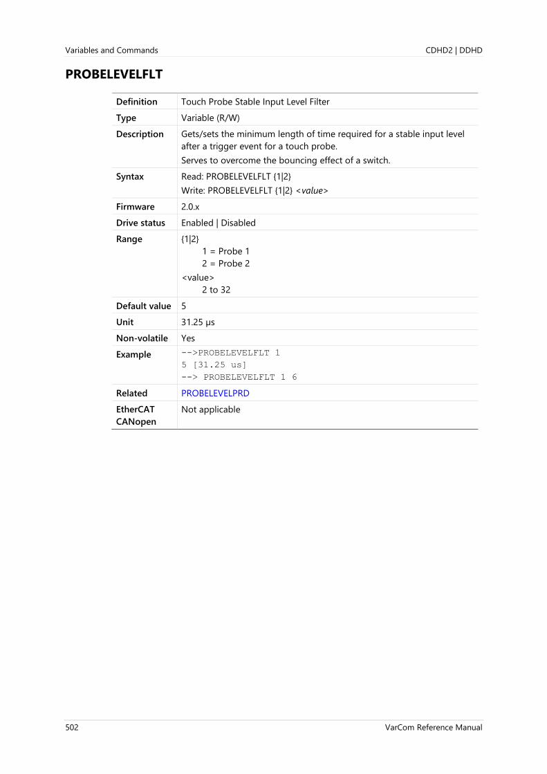
Variables and Commands CDHD2 | DDHD
502 VarCom Reference Manual
PROBELEVELFLT
Definition Touch Probe Stable Input Level Filter
Type Variable (R/W)
Description Gets/sets the minimum length of time required for a stable input level
after a trigger event for a touch probe.
Serves to overcome the bouncing effect of a switch.
Syntax Read: PROBELEVELFLT {1|2}
Write: PROBELEVELFLT {1|2} <value>
Firmware 2.0.x
Drive status Enabled | Disabled
Range {1|2}
1 = Probe 1
2 = Probe 2
<value>
2 to 32
Default value 5
Unit 31.25 µs
Non-volatile Yes
Example -->PROBELEVELFLT 1
5 [31.25 us]
--> PROBELEVELFLT 1 6
Related PROBELEVELPRD
EtherCAT
CANopen
Not applicable

CDHD2 | DDHD Variables and Commands
VarCom Reference Manual 503
PROBELEVELPRD
Definition Touch Probe Stable Input Level Duration
Type Variable (R/W)
Description Gets/sets the minimum length of time required for a stable input level
after a trigger event.
Serves to overcome the bouncing effect of a switch.
Syntax Read: PROBELEVELPRD
Write: PROBELEVELPRD <value>
Firmware 1.15.xx
Drive status Enabled | Disabled
Range 2 to 32
Default value 5
Unit 31.25 µs
Non-volatile Yes
Related PROBECONFIG
PROBESTATUS
EtherCAT
CANopen
214Bh, sub-index 0

Variables and Commands CDHD2 | DDHD
504 VarCom Reference Manual
PROBESTATUS
Definition Touch Probe Status
Type Variable (R)
Description Indicates whether the probe is enabled and which type of edge event
has occurred.
Syntax PROBESTATUS
Firmware 1.15.xx
Drive status Enabled | Disabled
Range Not applicable
Default value Not applicable
Unit Not applicable
Non-volatile No
Example Probe is switched off:
PROBECONFIG 1 0 0 0 2 h05
PROBESTATUS
Probe -1 Is Switched Off
No positive edge data stored
No negative edge data stored
Example Probe is switched on:
PROBECONFIG 1 1 0 0 2 h05
PROBESTATUS
Probe -1 Is Switched On
No positive edge data stored
Negative edge data stored
After edge event occurred:
PROBESTATUS
Probe -1 Is Switched On
No positive edge data stored
Negative edge data stored
Example Probe is switched on:
PROBECONFIG 1 1 0 0 1 h05
PROBESTATUS
Probe -1 Is Switched On
No positive edge data stored
Negative edge data stored
After edge event occurred:
PROBESTATUS
Probe -1 Is Switched On
Positive edge data stored
Negative edge data stored

CDHD2 | DDHD Variables and Commands
VarCom Reference Manual 505
Example Loading capture edge with idle value will clear the status:
PROBECONFIG 1 1 0 0 0 h05
Probe -1 Is Switched On
No positive edge data stored
No Negative edge data stored
Related PROBECONFIG
PROBECOUNTER
PROBEDATAFALL
PROBEDATARISE
PROBELEVELPRD
EtherCAT
CANopen
Not applicable
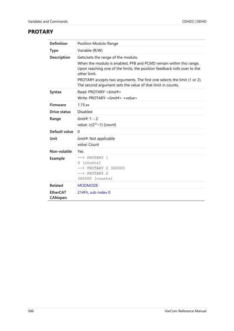
Variables and Commands CDHD2 | DDHD
506 VarCom Reference Manual
PROTARY
Definition Position Modulo Range
Type Variable (R/W)
Description Gets/sets the range of the modulo.
When the modulo is enabled, PFB and PCMD remain within this range.
Upon reaching one of the limits, the position feedback rolls over to the
other limit.
PROTARY accepts two arguments. The first one selects the limit (1 or 2).
The second argument sets the value of that limit in counts.
Syntax Read: PROTARY <limit#>
Write: PROTARY <limit#> <value>
Firmware 1.15.xx
Drive status Disabled
Range limit#: 1 – 2
value: ±(231–1) [count]
Default value 0
Unit limit#: Not applicable
value: Count
Non-volatile Yes
Example --> PROTARY 1
0 [counts]
--> PROTARY 2 360000
--> PROTARY 2
360000 [counts]
Related MODMODE
EtherCAT
CANopen
214Fh, sub-index 0

CDHD2 | DDHD Variables and Commands
VarCom Reference Manual 507
PTPTE
Definition PTP Generator Target Error
Type Variable (R)
Description Reports the target error during a motion profile, which is the distance
remaining to the destination in a point-to-point move.
Syntax PTPTE
Firmware 1.0.6
Drive status Enabled | Disabled
Range If MOTORTYPE 0 (Rotary): ±(231 -1) [rev]
If MOTORTYPE 2 (Linear): ±(231 -1) [pitch]
Default value Not applicable
Unit If MOTORTYPE 0 (Rotary):
UNITSROTPOS 0 = rev
UNITSROTPOS 1 = count
UNITSROTPOS 2 = deg
If MOTORTYPE 2 (Linear):
UNITSLINPOS 0 = pitch
UNITSLINPOS 1 = count
UNITSLINPOS 3 = mm
Non-volatile No
Related MOVEABS
MOVEINC
PCMD
PE
PTPVCMD
EtherCAT
CANopen
20B0h, sub-index 0
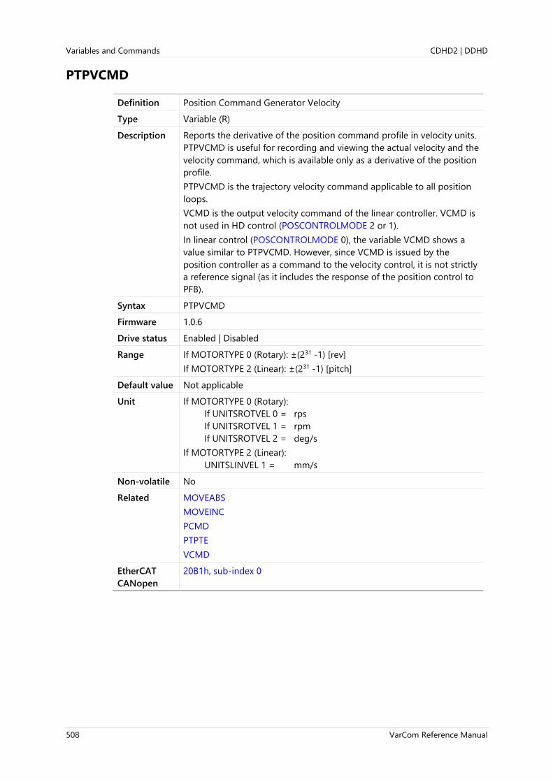
Variables and Commands CDHD2 | DDHD
508 VarCom Reference Manual
PTPVCMD
Definition Position Command Generator Velocity
Type Variable (R)
Description Reports the derivative of the position command profile in velocity units.
PTPVCMD is useful for recording and viewing the actual velocity and the
velocity command, which is available only as a derivative of the position
profile.
PTPVCMD is the trajectory velocity command applicable to all position
loops.
VCMD is the output velocity command of the linear controller. VCMD is
not used in HD control (POSCONTROLMODE 2 or 1).
In linear control (POSCONTROLMODE 0), the variable VCMD shows a
value similar to PTPVCMD. However, since VCMD is issued by the
position controller as a command to the velocity control, it is not strictly
a reference signal (as it includes the response of the position control to
PFB).
Syntax PTPVCMD
Firmware 1.0.6
Drive status Enabled | Disabled
Range If MOTORTYPE 0 (Rotary): ±(231 -1) [rev]
If MOTORTYPE 2 (Linear): ±(231 -1) [pitch]
Default value Not applicable
Unit If MOTORTYPE 0 (Rotary):
If UNITSROTVEL 0 = rps
If UNITSROTVEL 1 = rpm
If UNITSROTVEL 2 = deg/s
If MOTORTYPE 2 (Linear):
UNITSLINVEL 1 = mm/s
Non-volatile No
Related MOVEABS
MOVEINC
PCMD
PTPTE
VCMD
EtherCAT
CANopen
20B1h, sub-index 0

CDHD2 | DDHD Variables and Commands
VarCom Reference Manual 509
PWMFRQ
Definition PWM Frequency
Type Variable (R)
Description Gets the frequency of the PWM signals.
Syntax PWMFRQ
Firmware 1.0.6
Drive status Enabled | Disabled
Range 16.000
Default value 16.000
Unit kHz
Non-volatile No
Related DIPEAK
VBUS
EtherCAT
CANopen
20B2h, sub-index 0
Panel P 7 3 1 0

Variables and Commands CDHD2 | DDHD
510 VarCom Reference Manual
READY
Definition Drive Ready
Type Variable (R)
Description Indicates whether the drive is ready for activation with only external
remote enable switch still required (ACTIVE).
Syntax READY
Firmware 1.0.6
Drive status Enabled | Disabled
Range 0 = Faults exist or SWEN 0
1 = No faults exist and SWEN 1
Default value Not applicable
Unit Not applicable
Non-volatile No
Related ACTIVE
EN
FLT
K
REMOTE
ST
SWEN
EtherCAT
CANopen
2113h, sub-index 0

CDHD2 | DDHD Variables and Commands
VarCom Reference Manual 511
RECDONE
Definition Recording Done
Type Variable (R)
Description Indicates whether the RECORD command is done and data is available.
Syntax RECDONE
Firmware 1.0.6
Drive status Enabled | Disabled
Range 0 = Recording not finished
1 = Recording done; data available
Default value Not applicable
Unit Not applicable
Non-volatile No
Related GET
RECING
RECOFF
RECORD
RECRDY
RECTRIG
EtherCAT
CANopen
20E6h, sub-index 0

Variables and Commands CDHD2 | DDHD
512 VarCom Reference Manual
RECING
Definition Recording
Type Variable (R)
Description Indicates if data recording is in progress.
Syntax RECING
Firmware 1.0.6
Drive status Enabled | Disabled
Range 0 = Recording not in progress
1 = Recording in progress
Default value Not applicable
Unit Not applicable
Non-volatile No
Related RECDONE
RECOFF
RECORD
RECRDY
RECTRIG
EtherCAT
CANopen
20EBh, sub-index 0

CDHD2 | DDHD Variables and Commands
VarCom Reference Manual 513
RECLIST
Definition Recordable Variables List
Type Command
Description Returns a list of all variables that can be recorded by the RECORD
command.
Syntax RECLIST
Firmware 1.0.6
Drive status Enabled | Disabled
Range Not applicable
Default value Not applicable
Unit Not applicable
Non-volatile No
Related RECORD
EtherCAT
CANopen
Not applicable

Variables and Commands CDHD2 | DDHD
514 VarCom Reference Manual
RECOFF
Definition Stop Recording
Type Command
Description Stops an active recording.
Syntax RECOFF
Firmware 1.0.6
Drive status Enabled | Disabled
Range Not applicable
Default value Not applicable
Unit Not applicable
Non-volatile Not applicable
Related RECDONE
RECING
RECORD
RECRDY
RECTRIG
EtherCAT
CANopen
20E9h, sub-index 0

CDHD2 | DDHD Variables and Commands
VarCom Reference Manual 515
RECORD
Definition Record
Type Command
Description Captures real-time variables to memory for retrieval/display by the GET
command. RECORD must be set up before the RECTRIG command is
used. RECLIST returns the list of the recordable variables.
Note The RECORD command cannot be issued while IDENT is active.
Syntax RECORD sample_time num_points var1 [var2 … var6]
sample_time = 0 to 1000000 (multiples of 31.25 µs)
num_points = 1 to 2000
var = Name of a recordable system variable. System variables must be
preceded by a quotation mark (").
Firmware 1.0.6
Drive status Enabled | Disabled
Range Not applicable. Refer to Syntax, above.
Default value Not applicable
Unit Refer to Syntax, above
Non-volatile No
Example RECORD 32 100 "VCMD "V "ICMD
Records 100 points for VCMD, V, and ICMD every 1 milliseconds
Related GET
IDENT
RECDONE
RECING
RECLIST
RECOFF
RECRDY
RECTRIG
CANopen 20EAh, sub-index 1

Variables and Commands CDHD2 | DDHD
516 VarCom Reference Manual
RECRDY
Definition Ready to Record
Type Variable (R)
Description Indicates the ready status of the RECORD function. This variable can be
polled after a RECORD command is issued to determine if the system is
waiting for RECTRIG.
Syntax RECRDY
Firmware 1.0.6
Drive status Enabled | Disabled
Range 0 = RECTRIG has been received and record function is armed.
1 = Record function is waiting to be armed by RECTRIG command.
Default value Not applicable
Unit Not applicable
Non-volatile No
Related RECDONE
RECING
RECOFF
RECORD
RECTRIG
EtherCAT
CANopen
20ECh, sub-index 0

CDHD2 | DDHD Variables and Commands
VarCom Reference Manual 517
RECTRIG
Definition Trigger Recording
Type Command
Description Triggers the recorder. RECORD must be set up before a RECTRIG
command is issued.
The recording mechanism tracks the value of a system variable and
starts the recording as soon as the value goes above or below the
specified value. The recorder can also record a specified number of
points before the trigger condition occurs.
Known Limitation: If a trigger occurs before the pre-trigger buffer has
been filled, the beginning of the recording will have garbage data.
Syntax RECTRIG var level pre-trig {2|3}
var = Name of a recordable system variable that appears in
RECTRIGLIST. System variables must be preceded by a quotation
mark (").
level = Threshold value for the trigger
pre-trig = number of points to be recorded prior to trigger
2|3 = defines whether trigger occurs when absolute value of a
recorded is below (2) or above (3) the threshold. If an absolute
value is used, the threshold level cannot be negative.
RECTRIG “IMM = starts the recording immediately.
RECTRIG “CMD = starts the recording as soon as the next command is
sent to the drive.
RECTRIG “FLT = starts the recording as soon as a fault condition is
declared.
Firmware 1.0.6
Drive status Enabled | Disabled
Range Not applicable
Default value Not applicable
Unit Not applicable
Non-volatile No
Example rectrig "V 50 25 3
Recording will be triggered whenever the absolute value of V (Velocity)
is greater than 50 rpm.
Related GET
RECDONE
RECING
RECOFF
RECORD
RECRDY
RECTRIGLIST
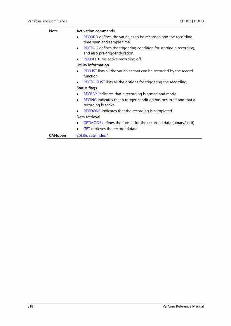
Variables and Commands CDHD2 | DDHD
518 VarCom Reference Manual
Note Activation commands
⚫ RECORD defines the variables to be recorded and the recording
time span and sample time.
⚫ RECTRIG defines the triggering condition for starting a recording,
and also pre-trigger duration.
⚫ RECOFF turns active recording off.
Utility information
⚫ RECLIST lists all the variables that can be recorded by the record
function.
⚫ RECTRIGLIST lists all the options for triggering the recording.
Status flags
⚫ RECRDY indicates that a recording is armed and ready.
⚫ RECING indicates that a trigger condition has occurred and that a
recording is active.
⚫ RECDONE indicates that the recording is completed
Data retrieval
⚫ GETMODE defines the format for the recorded data (binary/ascii)
⚫ GET retrieves the recorded data
CANopen 20E8h, sub-index 1

CDHD2 | DDHD Variables and Commands
VarCom Reference Manual 519
RECTRIGLIST
Definition Recording Trigger Variables List
Type Command
Description Returns a list of all trigger variables and options.
Any variable that can be read easily and quickly can serve as a recording
trigger. The variables listed below are the most commonly used trigger
sources. To view the complete list of trigger variables, issue the
command to the drive.
The recording trigger is defined by RECTRIG.
Note Some factory variables and commands, not intended for users, may
appear in the list.
Do not attempt to manipulate parameters that are not described in
the product documentation or Help.
Syntax RECTRIGLIST
Firmware 1.0.6
Drive status Enabled | Disabled
Range Commonly used dynamic signal variables:
ANIN1
ANIN2
ANOUT
CLVD
CLVQ
ELECTANGLE
FOLD
HWPEXT
HWPEXTCNTRLR
HWPEXTMACHN
I
ICMD
ID
IFOLD
ILIMACT
IN (IN1 – IN11)
IQ
IU
IV
MECHANGLE
MFOLD
MIFOLD
OUT (OUT1– OUT7
PCMD
PE
PELOOP
PFB
PTPTE
PTPVCMD
REMOTE
STOPPED
THERM
V
VBUSREADOUT
VCMD
VE
Commonly used status variables:
ACTIVE
HOMESTATE
LIMSWITCHNEG
LIMSWITCHPOS
Default value Not applicable
Unit Not applicable
Non-volatile No
Related RECTRIG
EtherCAT
CANopen
Not applicable

Variables and Commands CDHD2 | DDHD
520 VarCom Reference Manual
REFOFFSETVAL
Definition Offset After Homing
Type Variable (R/W)
Description Internal offset after homing.
When using an absolute encoder, this value is (saved and) used to
maintain a home reference position when drive power is cycled.
Syntax Read: REFOFFSETVAL
Write: REFOFFSETVAL <value>
Firmware 1.15.xx
Drive status Disabled
Range Not applicable
Default value 0
Unit If MOTORTYPE 0 (Rotary):
UNITSROTPOS 0 = rev
UNITSROTPOS 1 = count
UNITSROTPOS 2 = deg
If MOTORTYPE 2 (Linear):
UNITSLINPOS 0 = pitch
UNITSLINPOS 1 = count
UNITSLINPOS 3 = mm
Non-volatile Yes
Related HOMETYPE
PFBOFFSET
EtherCAT
CANopen
217Ch, sub-index 1

CDHD2 | DDHD Variables and Commands
VarCom Reference Manual 521
REGENFLTMODE
Definition Regeneration Resistor Fault Mode
Type Variable (R/W)
Description Defines how the drive responds to an excessive on-time condition of
the regeneration resistor.
Allows the user to set parameter to protect the external regeneration
resistor.
Syntax Read: REGENFLTMODE
Write: REGENFLTMODE<value>
Firmware 1.15.xx
Drive status Enabled | Disabled
Range 0 = Warning
1 = Fault
Default value 0
Unit Not applicable
Non-volatile Yes
Related REGENMAXONTIME
REGENMAXPOW
REGENPOW
REGENRES
EtherCAT
CANopen
Not applicable
Panel P 7 3 1 1

Variables and Commands CDHD2 | DDHD
522 VarCom Reference Manual
REGENMAXONTIME
Definition Regeneration Resistor Maximum On Time
Type Variable (R/W)
Description The maximum time for which the regeneration resistor may be
continually activated (on), in milliseconds.
Syntax Read: REGENMAXONTIME
Write: REGENMAXONTIME <value>
Firmware 1.15.xx
Drive status Enabled | Disabled
Range 10 to 100
Default value 40
Unit ms
Non-volatile Yes
Related REGENFLTMODE
REGENMAXPOW
REGENPOW
REGENRES
EtherCAT
CANopen
Not applicable
Panel P 7 3 1 2

CDHD2 | DDHD Variables and Commands
VarCom Reference Manual 523
REGENMAXPOW
Definition Regeneration Resistor Maximum Power
Type Variable (R)
Description Maximum calculated power of the regeneration resistor, in watts.
Syntax REGENMAXPOW
Firmware 1.20.6
Drive status Enabled | Disabled
Range -1 to 32767
Default value -1
Unit W
Non-volatile No
Related REGENFLTMODE
REGENMAXONTIME
REGENPOW
REGENRES
EtherCAT
CANopen
Not applicable
Panel P 7 3 1 3

Variables and Commands CDHD2 | DDHD
524 VarCom Reference Manual
REGENPOW
Definition Regeneration Resistor Power
Type Variable (R/W)
Description Power of the regeneration resistor, in watts.
Use REGENPOW -1 if the system does not have a regeneration resistor.
Note If the system has a regeneration resistor, a value of -1 for either
REGENRES or REGENPOW deactivates the regeneration resistor
overload protection algorithm.
Syntax Read: REGENPOW
Write: REGENPOW <value>
Firmware 1.15.xx
Drive status Enabled | Disabled
Range -1 to 32767
Default value -1
Unit W
Non-volatile Yes
Example -->regenpow
2 [W]
-->regenpow -1
-->regenpow
-1 [W]
Related REGENFLTMODE
REGENMAXONTIME
REGENMAXPOW
REGENRES
EtherCAT
CANopen
Not applicable
Panel P 7 3 1 4

CDHD2 | DDHD Variables and Commands
VarCom Reference Manual 525
REGENRES
Definition Regeneration Resistor Resistance
Type Variable (R/W)
Description Resistance of the regeneration resistor, in ohms.
Use REGENRES -1 if the system does not have a regeneration resistor.
Note If the system has a regeneration resistor, a value of -1 for either
REGENRES or REGENPOW deactivates the regeneration resistor
overload protection algorithm.
Syntax Read: REGENRES
Write: REGENRES <value>
Firmware 1.15.xx
Drive status Enabled | Disabled
Range -1 to 32767
Default value -1
Unit Ohm
Non-volatile Yes
Example -->regenres
2 [Ohm]
-->regenres -1
-->regenres
-1 [Ohm]
Related REGENFLTMODE
REGENMAXONTIME
REGENMAXPOW
REGENPOW
EtherCAT
CANopen
Not applicable
Panel P 7 3 1 5

Variables and Commands CDHD2 | DDHD
526 VarCom Reference Manual
RELAY
Definition Fault Relay Status
Type Variable (R)
Description Indicates the state of the fault relay.
Syntax RELAY
Firmware 1.0.6
Drive status Enabled | Disabled
Range 0 = Relay open
1 = Relay closed
Default value Not applicable
Unit Not applicable
Non-volatile No
Related ACTIVE
CLEARFAULTS
FLT
RELAYMODE
REMOTE
EtherCAT
CANopen
20B8h, sub-index 0
Panel P 4 0 5 1

CDHD2 | DDHD Variables and Commands
VarCom Reference Manual 527
RELAYMODE
Definition Fault Relay Mode
Type Variable (R/W)
Description Gets/sets a value that defines how the fault relay operates.
Syntax Read: RELAYMODE
Write: RELAYMODE <value>
Firmware 1.0.6
Drive status Enabled | Disabled
Range 0 = Relay opens upon fault.
1= Relay opens upon disable.
2 = Deactivated (RELAY not supported; typically due to hardware
limitation).
Default value 0
Unit Not applicable
Non-volatile Yes
Related ACTIVE
CLEARFAULTS
FLT
RELAY
REMOTE
EtherCAT
CANopen
20B9h, sub-index 0
Panel P 4 0 5 2

Variables and Commands CDHD2 | DDHD
528 VarCom Reference Manual
REMOTE
Definition Remote Hardware Enable Status
Type Variable (R)
Description Indicates the state of the external hardware enable input line.
Syntax REMOTE
Firmware 1.0.6
Drive status Enabled | Disabled
Range 0 = Remote enable input off.
1 = Remote enable input on.
Default value Not applicable
Unit Not applicable
Non-volatile No
Related ACTIVE
READY
RELAY
RELAYMODE
EtherCAT
CANopen
20BAh, sub-index 0

CDHD2 | DDHD Variables and Commands
VarCom Reference Manual 529
RESAMPLRANGE
Definition Resolver Amplitude Range
Type Variable (R/W)
Description Gets/sets the acceptable range of resolver sine/cosine signals,
expressed as a percentage, around their nominal value.
The default value of 35% means the sine/cosine signals are allowed to
deviate up to 35% from the nominal before an Out-Of-Range Fault is
declared.
Syntax Read: RESAMPLRANGE
Write: RESAMPLRANGE <value>
Firmware 1.0.6
Drive status Enabled | Disabled
Range 0 to 100
Default value 35
Unit %
Non-volatile Yes
Related FEEDBACKTYPE
RESBW
SININIT
SINPARAM
EtherCAT
CANopen
20BBh, sub-index 0
Panel P 2 0 2 8

Variables and Commands CDHD2 | DDHD
530 VarCom Reference Manual
RESBW
Definition Resolver Conversion Bandwidth
Type Variable (R/W)
Description Get/sets the resolver conversion bandwidth. High bandwidth produces
better dynamic tracking and less phase lag in high frequencies. Lower
bandwidth results in better noise reduction.
Resolvers typically enable slower dynamic tracking than encoders.
RESBW sets the most balanced value according to specific application
requirements.
Syntax Read: RESBW
Write: RESBW <value>
Firmware 1.0.6
Drive status Disabled
Range 200 to 800
Default value 300
Unit Hz
Non-volatile Yes
Related FEEDBACKTYPE
SININIT
VELFILTMODE
EtherCAT
CANopen
20BCh, sub-index 0
Panel P 2 0 0 8

CDHD2 | DDHD Variables and Commands
VarCom Reference Manual 531
RESFILTMODE
Definition Resolver Interpolation Mode
Type Variable (R/W)
Description Defines whether or not feedback position interpolation is performed on
the resolver feedback in order to generate a continuous stream of data.
The interpolation mode is useful since the resolver excitation signal is
slower than the feedback sampling.
Syntax Read: RESFILTMODE
Write: RESFILTMODE <value>
Firmware 1.4.6
Drive status Disabled
Range 0 = No interpolation
1 = Interpolation
Default value 0
Unit Not applicable
Non-volatile Yes
Related FEEDBACKTYPE
RESBW
EtherCAT
CANopen
Not applicable

Variables and Commands CDHD2 | DDHD
532 VarCom Reference Manual
SAVE
Definition Save Parameters
Type Command
Description Copies all system configuration variables from working RAM to non-
volatile memory.
This command must be executed in order to retain setting changes
during power cycling.
Syntax SAVE
Firmware 1.0.6
Drive status Enabled | Disabled
Range Not applicable
Default value Not applicable
Unit Not applicable
Non-volatile Not applicable
Related DUMP
FACTORYRESTORE
LOAD
EtherCAT
CANopen
1010h, sub-index 1
Panel C 0 0 0 6

CDHD2 | DDHD Variables and Commands
VarCom Reference Manual 533
SFB
Definition Secondary Feedback Position
Type Variable (R)
Description Gets the position value of the feedback device on the load, including
any offsets that have been added.
When dual loop control is active, the load feedback serves to control
positioning, while the motor feedback is used to control velocity and
current.
Syntax SFB
Firmware 1.15.xx
Drive status Enabled | Disabled
Range ±(263 - 1)
Default value Not applicable
Unit Set by the UNITSROTPOS and UNITSLINPOS variables, for rotary and
linear encoder respectively.
If SFBTYPE is rotary (bit 8=0):
UNITSROTPOS 0 = rev
UNITSROTPOS 1 = count
UNITSROTPOS 2 = deg
If SFBTYPE is linear (bit 8=1):
UNITSLINPOS 0 = pitch
UNITSLINPOS 1 = count
UNITSLINPOS 3 = mm
Non-volatile No
Related SFBMODE
SFBOFFSET
EtherCAT
CANopen
2161h, sub-index 0
Panel P 2 1 0 3

Variables and Commands CDHD2 | DDHD
534 VarCom Reference Manual
SFBACC
Definition Secondary Feedback Acceleration
Type Variable (R/W)
Description Gets/sets the acceleration value according to the feedback device on the
load.
SFBACC mirrors the value of ACC in order to maintain the correct value of
load feedback if SFBMODE changes.
If SFBMODE=1 (dual loop control), the value of ACC is automatically
written to SFBACC; conversely, the value of SFBACC is automatically
written to ACC. It is therefore sufficient to write values to ACC. SFBACC
will be updated accordingly.
Syntax Read: SFBACC
Write: SFBACC <value>
Firmware 2.0.x
Drive status Enabled | Disabled
Range If SFBTYPE is rotary (bit 8=0):
UNITSROTACC 0 = 0.004 to 16666.666
UNITSROTACC 1 = 0.23 to 1000000
UNITSROTACC 2 = 1.35 to 6000000
If SFBTYPE is linear (bit 8=1):
UNITSLINACC 1 = 0.12 to 533333.333
Default value If SFBTYPE is rotary (bit 8=0):
UNITSROTACC 0 = 10.000
UNITSROTACC 1 = 40000.000
UNITSROTACC 2 = 3600.000
UNITSROTACC 3 = 50.000
If SFBTYPE is linear (bit 8=1):
UNITSLINACC 1 = 320.000
Unit If SFBTYPE is rotary (bit 8=0):
UNITSROTACC 0 = rps/s
UNITSROTACC 1 = rpm/s
UNITSROTACC 2 = deg/s2
If SFBTYPE is linear (bit 8=1):
UNITSLINACC 1 = mm/s2
Non-volatile Yes
Related ACC
SFBMODE
EtherCAT
CANopen
21A9h, sub-index 0

CDHD2 | DDHD Variables and Commands
VarCom Reference Manual 535
SFBDEC
Definition Secondary Feedback Deceleration
Type Variable (R/W)
Description Gets/sets the deceleration value according to the feedback device on
the load.
SFBDEC mirrors the value of DEC in order to maintain the correct value
of motor feedback or load feedback if SFBMODE changes.
If SFBMODE=1 (dual loop control), the value of DEC is automatically
written to SFBDEC; conversely, any the value of SFBDEC is automatically
written to DEC. It is therefore sufficient to write values to DEC. SFBDEC
will be updated accordingly.
Syntax Read: SFBDEC
Write: SFBDEC <value>
Firmware 2.0.x
Drive status Enabled | Disabled
Range If SFBTYPE is rotary (bit 8=0):
UNITSROTACC 0 = 0.004 to 16666.666
UNITSROTACC 1 = 0.23 to 1000000
UNITSROTACC 2 = 1.38 to 6000000
If SFBTYPE is linear (bit 8=1):
UNITSLINACC 1 = 0.12 to 533333.333
Default value If SFBTYPE is rotary (bit 8=0):
UNITSROTACC 0 = 10.000
UNITSROTACC 1 = 600.000
UNITSROTACC 2 = 3600.000
UNITSROTACC 3 = 50.000
If SFBTYPE is linear (bit 8=1):
UNITSLINACC 1 = 320.000
Unit If SFBTYPE is rotary (bit 8=0):
UNITSROTACC 0 = rps/s
UNITSROTACC 1 = rpm/s
UNITSROTACC 2 = deg/s2
If SFBTYPE is linear (bit 8=1):
UNITSLINACC 1 = mm/s2
Non-volatile Yes
Related DEC
MDEC
SFBMODE
EtherCAT
CANopen
21ABh, sub-index 0

Variables and Commands CDHD2 | DDHD
536 VarCom Reference Manual
SFBDIR
Definition Secondary Feedback Direction
Type Variable (R/W)
Description The positive direction of feedback from the load.
Syntax Read: SFBDIR
Write: SFBDIR <value>
Firmware 2.0.x
Drive status Disabled
Range 0 = Normal; feedback direction not inverted
1 = Feedback direction inverted
Default value 0
Unit Not applicable
Non-volatile Yes
Related DIR
EtherCAT
CANopen
2186h, sub-index 0

CDHD2 | DDHD Variables and Commands
VarCom Reference Manual 537
SFBENCTYPE
Definition Secondary Feedback Type AB Quad Encoder
Type Variable (R/W)
Description Gets/sets the type of AB quadrature encoder used as a secondary
feedback device. Applicable only if SFBTYPE=2.
Syntax Read: SFBENCTYPE
Write: SFBENCTYPE <value>
Firmware 2.0.x
Drive status Disabled
Range 1 = Encoder with A/B/Z signals
3 = Encoder with A/B signals
Default value 1
Unit Not applicable
Non-volatile Yes
Related
EtherCAT
CANopen
2187h, sub-index 0

Variables and Commands CDHD2 | DDHD
538 VarCom Reference Manual
SFBMODE
Definition Secondary Feedback Mode
Type Variable (R/W)
Description Defines whether secondary feedback is enabled and whether it is used
for the control loop.
Note: Dual loop control is applicable only if POSCONTROLMODE=0
(linear position controller).
In dual loop control, two feedback devices (typically, encoders) are
connected to one axis: one feedback device is mounted on the motor
and a secondary feedback encoder is connected to the load. The load
feedback is used for the position control loop, while the motor feedback
is used for controlling velocity and current.
PFB is the position generated by the motor feedback device.
SFB is the position generated by the secondary feedback device.
The drive supports secondary feedback devices whose output is an
analog voltage (SFBTYPE=1). The secondary feedback analog voltage is
converted into an absolute position, SFB.
Dual loop configuration requires scaling of the secondary feedback
relative to the motor feedback, along with a particular tuning method,
as shown in the diagram below.
Syntax Read: SFBMODE
Write: SFBMODE <value>
Firmware 2.0.x
Drive status Disabled
Range 0 = Secondary feedback disabled; dual loop mode inactive.
Motor feedback is connected via connector C4.
1 = Secondary feedback enabled; dual loop mode active.
Load feedback is used for the position control loop;
load feedback is connected via connector C3.
Motor feedback is used for velocity and current control;
motor feedback isconnected via connector C4.
2 = Secondary feedback enabled; dual loop mode inactive.
SFB is calculated and can be read, but is not applied to the control
loop. Motor feedback (PFB) is used for the position control loop.
Motor feedback is connected via connector C4.
3 = Reserved.
4= Secondary feedback disabled; dual loop mode inactive.
Motor feedback is connected via connector C3.
Applicable only for incremental A/B encoders.
Note When using SFBMODE=1, GEARMODE must be set to 0, 1 or 2.
Default value 0
+/- VCMD +/- ICMDPCMD
SFB d/dt
POS CTRL VEL CTRL
PFBLinear

CDHD2 | DDHD Variables and Commands
VarCom Reference Manual 539
Unit Not applicable
Non-volatile Yes
Related SFB
SFBOFFSET
SFBTYPE
LMUNITSDEN
LMUNITSNUM
SFBVEL
EtherCAT
CANopen
2139h, sub-index 0
Panel P 2 1 0 7

Variables and Commands CDHD2 | DDHD
540 VarCom Reference Manual
SFBOFFSET
Definition Secondary Feedback Offset
Type Variable (R/W)
Description Gets/sets the offset value added to the secondary feedback (SFB).
Syntax Read: SFBOFFSET
Write: SFBOFFSET <value>
Firmware 1.15.xx
Drive status Enabled | Disabled
Range Not applicable
Default value Not applicable
Unit 0.000 [SFB user unit]
Non-volatile Yes
Related SFB
SFBMODE
EtherCAT
CANopen
2162h, sub-index 0
Panel P 2 1 0 8

CDHD2 | DDHD Variables and Commands
VarCom Reference Manual 541
SFBRES
Definition Secondary Feedback Resolution
Type Variable (R/W)
Description The resolution of the feedback device on the load, in number of lines
per revolution or lines per millimeter.
Syntax Read: SFBRES
Write: SFBRES <value>
Firmware 2.0.x
Drive status Disabled
Range 16 to 256,000,000
Default value 32768
Unit Rotary encoder: PPR
Linear: lines/1 mm
Non-volatile Yes
Related SFB
SFBVEL
EtherCAT
CANopen
21A6h, sub-index 0

Variables and Commands CDHD2 | DDHD
542 VarCom Reference Manual
SFBTYPE
Definition Secondary Feedback Type
Type Variable (R/W)
Description Defines the type of secondary encoder (rotary or linear) and the type of
communication interface.
Syntax Read: SFBTYPE
Write: SFBTYPE <value>
Firmware 2.0.x
Drive status Disabled
Range The value of SFBTYPE is defined by bit values:
Bit
8
Bits
0–7 Value Description
0 0 = 0 Not active
0 2 = 2 Load rotary feedback device with
incremental AB quadrature encoder
0 11 = 11 Load rotary feedback device – EnDat 2.x
communication only
0 16 = 16 Load rotary feedback device – BiSS-C
interface
1 2 = 258 Load linear feedback device with
incremental AB quadrature encoder
1 11 = 267 Load linear feedback device – EnDat 2.x
communication only
1 16 = 272 Load linear feedback device – BiSS-C
interface
Default value 0
Unit Not applicable
Non-volatile Yes
Related SFB
SFBMODE
EtherCAT
CANopen
213Ah, sub-index 0
Panel P 2 1 1 3

CDHD2 | DDHD Variables and Commands
VarCom Reference Manual 543
SFBVCMD
Definition External Loop Velocity Command
Type Variable (R)
Description The velocity command generated at the external loop controller
Syntax SFBVCMD
Firmware 2.0.x
Drive status Enabled | Disabled
Range ±(231 - 1)
Default value Not applicable
Unit
Non-volatile No
Related
EtherCAT
CANopen
Not applicable

Variables and Commands CDHD2 | DDHD
544 VarCom Reference Manual
SFBVEL
Definition Secondary Feedback Load Velocity
Type Variable (R)
Description The velocity according to the feedback device on the load.
Syntax SFBVEL
Firmware 2.0.x
Drive status Enabled | Disabled
Range Not applicable
Default value Not applicable
Unit If SFBTYPE is rotary (bit 8=0):
If UNITSROTVEL 0 = rps
If UNITSROTVEL 1 = rpm
If UNITSROTVEL 2 = deg/s
If SFBTYPE is linear (bit 8=1):
UNITSLINVEL 1 = mm/s
Non-volatile No
Related SFB
SFBMODE
EtherCAT
CANopen
2141h, sub-index 0

CDHD2 | DDHD Variables and Commands
VarCom Reference Manual 545
SFBVLIM
Definition Secondary Feedback Velocity Limit
Type Variable (R/W)
Description User-defined velocity limit for the feedback device on the load.
Syntax Read: SFBVLIM
Write: SFBVLIM <value>
Firmware 2.0.x
Drive status Enabled | Disabled
Range Not applicable
Default value Not applicable
Unit If SFBTYPE is rotary (bit 8=0):
If UNITSROTVEL 0 = rps
If UNITSROTVEL 1 = rpm
If UNITSROTVEL 2 = deg/s
If SFBTYPE is linear (bit 8=1):
UNITSLINVEL 1 = mm/s
Non-volatile No
Related SFBVEL
EtherCAT
CANopen
Not applicable

Variables and Commands CDHD2 | DDHD
546 VarCom Reference Manual
SININIT
Definition Sine/Cosine Calibration Command
Type Command
Description Activates a procedure that calibrates sine encoder or resolver sine and
cosine signals. The calibration serves to reduce harmonic errors in the
sine encoder or resolver reading.
The procedure averages sine encoder or resolver signals over several
motor turns to determine the gain and offset correction.
The progress of the procedure is reported by the SININITST command,
and the resulting calibration gains and offsets are reported by
SINPARAM.
Syntax SININIT
Firmware 1.0.6
Drive status Enabled | Disabled
Range Not applicable
Default value Not applicable
Unit Not applicable
Non-volatile Not applicable
Related FEEDBACKTYPE
RESBW
SININITMODE
SININITST
SINPARAM
EtherCAT
CANopen
20BEh, sub-index 0
Panel C 0 0 1 4

CDHD2 | DDHD Variables and Commands
VarCom Reference Manual 547
SININITMODE
Definition Sine/Cosine Calibration Mode
Type Variable (R/W)
Description Enables/disables the automatic calibration of sine encoder or resolver
sine and cosine signals at power up.
Syntax Read: SININITMODE
Write: SININITMODE <value>
Firmware 1.0.6
Drive status Enabled | Disabled
Range 0 = Automatic calibration of sine and cosine signals disabled
1 = Automatic calibration of sine and cosine signals enabled
Default value 0
Unit Not applicable
Non-volatile Yes
Related FEEDBACKTYPE
RESBW
SININITST
SINPARAM
EtherCAT
CANopen
20BFh, sub-index 0
Panel P 2 0 2 9

Variables and Commands CDHD2 | DDHD
548 VarCom Reference Manual
SININITST
Definition Sine/Cosine Calibration Status
Type Variable (R)
Description Reports the status of the sine encoder or resolver calibration procedure.
Syntax SININITST
Firmware 1.0.6
Drive status Enabled | Disabled
Range 0 = Not started, or completed
1 = In progress
2 = Velocity is too high
Default value Not applicable
Unit Not applicable
Non-volatile No
Related FEEDBACKTYPE
HWPOS
RESBW
SINPARAM
SININITMODE
EtherCAT
CANopen
20C0h, sub-index 0

CDHD2 | DDHD Variables and Commands
VarCom Reference Manual 549
SINPARAM
Definition Sine/Cosine Calibration Parameters
Type Variable (R)
Description Returns the parameters that are used for calibrating sine encoder or
resolver sine and cosine signals. The parameters are in hexadecimal
representation.
Syntax SINPARAM
Firmware 1.0.6
Drive status Enabled | Disabled
Range Not applicable
Default value Not applicable
Unit Not applicable
Non-volatile No
Related SINPARAM
SININITST
FEEDBACKTYPE
CANopen 20C1h, sub-index 0

Variables and Commands CDHD2 | DDHD
550 VarCom Reference Manual
SKTEMPVOLT
Definition Sankyo Temperature and Battery Voltage
Type Variable (R)
Description Reads the temperature of the Sankyo encoder and the voltage of the
backup battery.
The values are not calibrated and should be used for trend indication
only, and not as accurate indications.
The battery voltage is read only once, at power up.
Syntax SKTEMPVOLT
Firmware 1.15.xx
Drive status Enabled | Disabled
Range
Default value
Unit °C
Non-volatile No
Related SKTURNRESET
THERM
TMTEMP
EtherCAT
CANopen
Not applicable

CDHD2 | DDHD Variables and Commands
VarCom Reference Manual 551
SKTURNRESET
Definition Sankyo Multi-Turn Reset
Type Command
Description Resets the counter of a Sankyo multi-turn encoder.
SKTURNRESET clears the encoder’s internal faults and resets the multi-
turn counter. This prevents unpredictable values in the multi-turn
position counter if the backup battery becomes disconnected and the
encoder is not being powered by the drive.
If the backup battery is disconnected while the encoder is not
connected to the drive, an Absolute Encoder Battery Fault is issued. To
clear this fault, use the SKTURNRESET command, and then use the
CLEARFAULT command.
Syntax SKTURNRESET
Firmware 1.15.xx
Drive status Disabled
Range Not applicable
Default value Not applicable
Unit Not applicable
Non-volatile Not applicable
Related CLEARFAULTS
SKTEMPVOLT
EtherCAT
CANopen
215Ah, sub-index 0

Variables and Commands CDHD2 | DDHD
552 VarCom Reference Manual
SRVSNSINFO
Definition sensAR Encoder Info
Type Variable (R)
Description Returns information about the sensAR encoder.
A valid response includes the following data:
⚫ Production information – serial and product numbers of the device
⚫ Hardware – PCB and BOM revisions
⚫ Software – Firmware version info and sensAR protocol version
⚫ Online data:
Temperature reading
Raw velocity and in-turn position values
Current sensAR faults and warnings information
Syntax SRVSNSINFO
Firmware 1.15.xx
Drive status Enabled | Disabled
Range Not applicable
Default value Not applicable
Unit Not applicable
Non-volatile No
Example -->SRVSNSINFO
sensAR Magnetic Encoder
------------------------------
Production Information:
Encoder:
P/N: PRDr0099000z-02
Rev: 01
S/N: I1914_00000015
Stator Assembly:
P/N: PRDr0099STAT-02
Rev: 01
S/N: S1314_00000015
Hardware:
PCB Rev: H0003
BOM Rev: H0000
Software:
FW Version: 2.0.7
FW Version Date: 20140922
Comm Protocol Version: 002.005.006
Online data:
Device Temperature: 39C
Raw in-turn position value: 3978751

CDHD2 | DDHD Variables and Commands
VarCom Reference Manual 553
Raw velocity value: 0
No faults exist on sensAR
Related
CANopen 214Ch, sub-index 1

Variables and Commands CDHD2 | DDHD
554 VarCom Reference Manual
ST
Definition Drive Status Messages
Type Command
Description Returns detailed drive status messages.
Syntax ST
Firmware 1.0.6
Drive status Enabled | Disabled
Range Not applicable
Default value Not applicable
Unit Not applicable
Non-volatile No
Example -->st
Drive Active
Related ACTIVE
FLT
FLTHIST
READY
REMOTE
SWEN
CANopen 2114h, sub-index 1

CDHD2 | DDHD Variables and Commands
VarCom Reference Manual 555
STALLTIME
Definition Stall Time
Type Variable (R/W)
Description The minimum length of time at which a stall condition generates a stall
fault.
A stall condition occurs when [I > MICONT] and [I > 0.9ILIM] and [V <
STALLVEL].
A stall fault occurs whenever the duration of a stall condition exceeds
STALLTIME.
The drive’s digital display shows F3 when a stall fault occurs.
Syntax Read: STALLTIME
Write: STALLTIME <value>
Firmware 1.3.2
Drive status Enabled | Disabled
Range 0 to 10000
Default value 0 = Fault inhibited
Unit ms
Non-volatile Yes
Related STALLVEL
EtherCAT
CANopen
Not applicable
Panel P 7 1 1 1

Variables and Commands CDHD2 | DDHD
556 VarCom Reference Manual
STALLVEL
Definition Stall Velocity
Type Variable (R/W)
Description The velocity threshold for entering a stall condition.
A stall condition occurs when [I > MICONT] and [I > 0.9ILIM] and [V <
STALLVEL].
A stall fault occurs whenever a stall condition exceeds STALLTIME.
Syntax Read: STALLVEL
Write: STALLVEL<value>
Firmware 1.3.2
Drive status Enabled | Disabled
Range If MOTORTYPE 0 (Rotary): (231 -1) [rpm]
If MOTORTYPE 2 (Linear): (231 -1) [mm/s]
Default value 10.000 rpm
Unit If MOTORTYPE 0 (Rotary):
If UNITSROTVEL 0 = rps
If UNITSROTVEL 1 = rpm
If UNITSROTVEL 2 = deg/s
If MOTORTYPE 2 (Linear):
UNITSLINVEL 1 = mm/s
Non-volatile Yes
Related STALLTIME
EtherCAT
CANopen
Not applicable
Panel P 7 1 1 2

CDHD2 | DDHD Variables and Commands
VarCom Reference Manual 557
STAT
Definition Drive Status Summary Word
Type Command
Description Outputs a drive status summary word.
Firmware 1.0.6
Syntax STAT
Drive status Enabled | Disabled
Range Not applicable
Default value Not applicable
Unit Hexadecimal
Non-volatile No
Example -->stat
H0023
-->
Related ST
STATUS
EtherCAT
CANopen
Not applicable

Variables and Commands CDHD2 | DDHD
558 VarCom Reference Manual
STATUS
Definition Drive Status Detail Words
Type Command
Description Outputs a series of drive status summary words.
Firmware STATUS
Syntax 1.0.6
Drive status Enabled | Disabled
Range Not applicable
Default value Not applicable
Unit Hexadecimal
Non-volatile No
Example -->status
H0009 H0000000000060800 H00C0 H0000
-->
Related ST
STAT
EtherCAT
CANopen
Not applicable

CDHD2 | DDHD Variables and Commands
VarCom Reference Manual 559
STEP
Definition Step Command
Type Command
Description Generates a step or square wave velocity command.
This command is similar to the J command, but allows repetition of
STEP to create a square wave velocity command.
Syntax STEP {duration1} {velocity1} [duration2 velocity2]
Firmware 1.0.6
Drive status Disabled
Range duration 1/2 = unlimited positive value
velocity 1/2 = -VLIM to +VLIM
Default value Not applicable
Unit Duration = ms
Velocity =
If MOTORTYPE 0 (Rotary):
If UNITSROTVEL 0 = rps
If UNITSROTVEL 1 = rpm
If UNITSROTVEL 2 = deg/s
If MOTORTYPE 2 (Linear):
UNITSLINVEL 1 = mm/s
Non-volatile Not applicable
Related ACC
J
OPMODE
RECORD
STOP
VLIM
EtherCAT
CANopen
2115h, sub-index 1

Variables and Commands CDHD2 | DDHD
560 VarCom Reference Manual
STOP
Definition Stop Motion Command
Type Command
Description Stops motion in OPMODE 0 (J and STEP commands) and OPMODE 2
(T command). Unlike the K command, the drive is not disabled using
the STOP command.
In OPMODE 1 or 3, STOP is ignored.
Note Do not use STOP to stop motion generated by HOMECMD.
To stop a homing procedure, use the command HOMECMD 0.
Syntax STOP
Firmware 1.0.6
Drive status Disabled
Range Not applicable
Default value Not applicable
Unit Not applicable
Non-volatile Not applicable
Related DEC
DECSTOP
J
STEP
EtherCAT
CANopen
Not applicable

CDHD2 | DDHD Variables and Commands
VarCom Reference Manual 561
STOPDIST
Definition Standstill Distance Window
Type Variable (R/W)
Description The maximum deviation within which the motor is considered to be at a
standstill.
The motor is considered to be at a standstill when the following
condition is in effect for at least 1 ms: ABS(PFBinitial - PFB) < STOPDIST
Syntax Read: STOPDIST
Write: STOPDIST<value>
Firmware 2.0.x
Drive status Disabled
Range 0 to 1
Default value 0.1
Unit degree
Non-volatile Yes
Related
EtherCAT
CANopen
Not applicable

Variables and Commands CDHD2 | DDHD
562 VarCom Reference Manual
STOPPED
Definition Position Motion Ended
Type Variable (R)
Description Reports whether the position profile generated by MOVEINC and
MOVEABS has been completed, therefore allowing the next command
to be issued.
STOPPED is updated while drive is operating in OPMODE 8. It is also
updated in OPMODE 0 provided the HD velocity controller is active
(VELCONTROLMODE=7).
Syntax Read: STOPPEDDURATE
Write: STOPPEDDURATE <value>
Firmware 1.0.6
Drive status Enabled | Disabled
Range -1 = Movement was interrupted (e.g., due to Disable or Hold)
0 = Not completed
1 = Profile completed
2 = Profile completed and drive is in position (INPOS=1)
Default value Not applicable
Unit Not applicable
Non-volatile No
Related HOLD
PEINPOS
PEINPOSTIME
PEMAX
PTPVCMD
V
VCMD
VELCONTROLMODE
EtherCAT
CANopen
2116h, sub-index 0
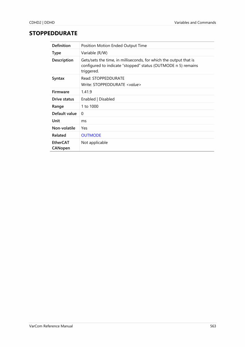
CDHD2 | DDHD Variables and Commands
VarCom Reference Manual 563
STOPPEDDURATE
Definition Position Motion Ended Output Time
Type Variable (R/W)
Description Gets/sets the time, in milliseconds, for which the output that is
configured to indicate “stopped” status (OUTMODE n 5) remains
triggered.
Syntax Read: STOPPEDDURATE
Write: STOPPEDDURATE <value>
Firmware 1.41.9
Drive status Enabled | Disabled
Range 1 to 1000
Default value 0
Unit ms
Non-volatile Yes
Related OUTMODE
EtherCAT
CANopen
Not applicable

Variables and Commands CDHD2 | DDHD
564 VarCom Reference Manual
SWEN
Definition Software Enable Status
Type Variable (R)
Description Indicates the state of software enable. This condition can be toggled
using the EN and K commands.
Syntax SWEN
Firmware 1.0.6
Drive status Enabled | Disabled
Range 0 = Software enable switch off (K command has been issued)
1 = Software enable switch on (EN command has been issued)
Default value Not applicable
Unit Not applicable
Non-volatile No
Related ACTIVE
EN
FLT
K
READY
REMOTE
ST
SWENMODE
EtherCAT
CANopen
20A2h, sub-index 0

CDHD2 | DDHD Variables and Commands
VarCom Reference Manual 565
SWENMODE
Definition Software Enable on Power-Up
Type Variable (R/W)
Description Gets/sets the state of the Software Enable switch when the drive is
powered up.
Requires COMMODE=0.
SWENMODE is applicable only to drives using serial communication
(COMMODE=0).
SWENMODE is not applicable to drives using CANopen and EtherCAT
communication (COMMODE=1).
Syntax Read: SWENMODE
Write: SWENMODE <value>
Firmware 1.0.6
Drive status Enabled | Disabled
Range 0 = At power up, Software Enable is off
1 = At power up, Software Enable is on
2 = At power up, Software Enable is on, and phase find is automatically
performed if required by the motor (MENCTYPE=4)
Default value 0
Unit Not applicable
Non-volatile Yes
Related ACTIVE
COMMODEEN
READY
SWEN
EtherCAT
CANopen
Not applicable

Variables and Commands CDHD2 | DDHD
566 VarCom Reference Manual
SYNCSOURCE
Definition Synchronization Mode
Type Variable (R/W)
Description Sets the method used to synchronize the drive clock to an external sync
signal.
When the drive detects a SYNC signal from EtherCAT or CANopen, it
automatically sets SYNCSOURCE to a value of 5 or 6, respectively.
Syntax Read: SYNCSOURCE
Write: SYNCSOURCE <value>
Firmware 1.0.6
Drive status Enabled | Disabled
Range 0 = Disabled; no sync
1 = Sync drive clock to controller based on fast digital input 5
2 = Sync drive clock to controller based on fast digital input 6
3 = Sync drive clock based on pulse differential input (Pulse &
Direction)
4 = Sync signal source is pulse input from Machine I/F
5 = Automatically set in EtherCAT drive (EC and EB models). Read only.
6 = Automatically set in CAN drive (AF model). Read only.
Default value 0
Unit Not applicable
Non-volatile Yes
Related INMODE
EtherCAT
CANopen
20C2h, sub-index 0

CDHD2 | DDHD Variables and Commands
VarCom Reference Manual 567
T
Definition Current Command
Type Command
Description Sets the current in OPMODE 2 (serial current mode).
This command is subject to current limits, clamps, and digital filtering,
and it is set to zero whenever the drive is enabled or disabled.
The commands STOP and K , and changing the operating mode, also
zero the value of T.
Syntax T Queries
T {current [duration]} Writes
Firmware 1.0.6
Drive status Enabled
Range Not applicable
Default value Not applicable
Unit current = A (peak)
duration = ms
Non-volatile Not applicable
Related I
ICMD
ILIM
OPMODE
EtherCAT
CANopen
6071h, sub-index 0

Variables and Commands CDHD2 | DDHD
568 VarCom Reference Manual
TF
Definition Tracking Factor
Type Variable (R/W)
Description Gets/sets the derivative factor for tracking with PDFF velocity controller.
0 = No derivative factor
100 = Derivative factor to match bandwidth and not overshoot.
200 = Derivative factor to match PI control; may overshoot.
Intermediate values are interpolated.
Syntax Read: TF
Write: TF <value>
Firmware 1.0.6
Drive status Enabled | Disabled
Range 0 to 200
Default value 100
Unit %
Non-volatile Yes
Related BW
LMJR
MJ
VELCONTROLMODE
EtherCAT
CANopen
20C3h, sub-index 0

CDHD2 | DDHD Variables and Commands
VarCom Reference Manual 569
THERM
Definition Motor Over-Temperature
Type Variable (R)
Description The state of the motor thermostat input, which indicates whether an
over-temperature condition exists.
Syntax THERM
Firmware 1.0.6
Drive status Enabled | Disabled
Range 0 = Thermostat input closed (normal) or ignored (THERMODE 3).
1 = Thermostat input open, indicating overheating
Default value Not applicable
Unit Not applicable
Non-volatile No
Related THERMODE
THERMREADOUT
THERMTRIPLEVEL
THERMCLEARLEVEL
THERMTIME
THERMTYPE
EtherCAT
CANopen
20C4h, sub-index 0

Variables and Commands CDHD2 | DDHD
570 VarCom Reference Manual
THERMCLEARLEVEL
Definition Motor Over-Temperature Clear Fault Level
Type Variable (R/W)
Description The level at which a motor over-temperature fault is cleared.
Syntax Read: THERMCLEARLEVEL
Write: THERMCLEARLEVEL <value>
Firmware 1.0.6
Drive status Enabled | Disabled
Range 0 to 1000000
Default value 100
Unit Ohm
Non-volatile Yes
Related THERMODE
THERMTRIPLEVEL
EtherCAT
CANopen
20C5h, sub-index 0
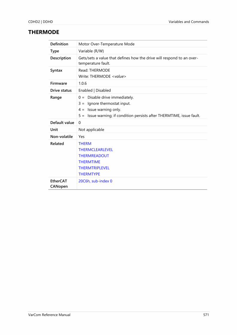
CDHD2 | DDHD Variables and Commands
VarCom Reference Manual 571
THERMODE
Definition Motor Over-Temperature Mode
Type Variable (R/W)
Description Gets/sets a value that defines how the drive will respond to an over-
temperature fault.
Syntax Read: THERMODE
Write: THERMODE <value>
Firmware 1.0.6
Drive status Enabled | Disabled
Range 0 = Disable drive immediately.
3 = Ignore thermostat input.
4 = Issue warning only.
5 = Issue warning; if condition persists after THERMTIME, issue fault.
Default value 0
Unit Not applicable
Non-volatile Yes
Related THERM
THERMCLEARLEVEL
THERMREADOUT
THERMTIME
THERMTRIPLEVEL
THERMTYPE
EtherCAT
CANopen
20C6h, sub-index 0

Variables and Commands CDHD2 | DDHD
572 VarCom Reference Manual
THERMREADOUT
Definition Motor Temperature
Type Variable (R)
Description Indicates the value of the motor temperature.
For sensAR feedback, indicates motor temperature, in Celsius degrees.
For all other feedback devices with either NTC or PTC sensor, indicates
the sensor resistance, in ohm.
Syntax THERMREADOUT
Firmware 1.0.6
Drive status Enabled | Disabled
Range 0 to 1000000
Default value Not applicable
Unit °C sensAR feedback device
Ohm non-sensAR feedback device
Non-volatile No
Related THERM
THERMODE
THERMTIME
THERMTYPE
EtherCAT
CANopen
20C7h, sub-index 0

CDHD2 | DDHD Variables and Commands
VarCom Reference Manual 573
THERMTIME
Definition Motor Over-Temperature Time
Type Variable (R/W)
Description Gets/sets the number of seconds the drive will wait after motor over-
temperature detection before it opens the fault relay.
Syntax Read: THERMTIME
Write: THERMTIME <value>
Firmware 1.0.6
Drive status Enabled | Disabled
Range 0 to 300
Default value 30
Unit second
Non-volatile Yes
Related THERM
THERMODE
THERMREADOUT
THERMTYPE
EtherCAT
CANopen
20C8h, sub-index 0

Variables and Commands CDHD2 | DDHD
574 VarCom Reference Manual
THERMTRIPLEVEL
Definition Motor Over-Temperature Fault Level
Type Variable (R/W)
Description Indicates the motor over-temperature fault level.
Syntax THERMTRIPLEVEL
Firmware 1.0.6
Drive status Enabled | Disabled
Range 0 to 1000000
Default value 150
Unit Ohm
Non-volatile Yes
Related THERMCLEARLEVEL
THERMODE
EtherCAT
CANopen
20C9h, sub-index 0

CDHD2 | DDHD Variables and Commands
VarCom Reference Manual 575
THERMTYPE
Definition Motor Over-Temperature Type
Type Variable (R/W)
Description Gets/sets the value that indicates the type of motor temperature sensor.
Syntax Read: THERMTYPE
Write: THERMTYPE <value>
Firmware 1.0.6
Drive status Enabled | Disabled
Range 0 = Positive temperature coefficient (PTC)
1 = Negative temperature coefficient (NTC)
Default value 0
Unit Not applicable
Non-volatile Yes
Related THERM
THERMODE
THERMREADOUT
THERMTIME
EtherCAT
CANopen
20CAh, sub-index 0

Variables and Commands CDHD2 | DDHD
576 VarCom Reference Manual
TMTEMP
Definition Tamagawa Temperature
Type Variable (R)
Description Indicates the temperature of a Tamagawa absolute encoder.
Note The value is read from a specific address 0x4F, and is valid only for
certain Tamagawa devices.
If the drive is not connected to the particular type of encoder, the
response to TMTEMP will be “MENCTYPE Mismatch”.
Syntax TMTEMP
Firmware 1.2.12
Drive status Enabled | Disabled
Range Not applicable
Default value Not applicable
Unit °C (relevant for Tamagawa encoder only)
Non-volatile No
Related MENCTYPE
TMTURNRESET
EtherCAT
CANopen
Not applicable
Panel P 2 0 3 0

CDHD2 | DDHD Variables and Commands
VarCom Reference Manual 577
TMTURNRESET
Definition Tamagawa Multi-Turn Reset
Type Command
Description Resets the position counter of a Tamagawa multi-turn encoder.
Note When using a Tamagawa 17-bit multi-turn encoder, TMTURNRESET
must be issued prior to a CLEARFAULT command.
Syntax TMTURNRESET
Firmware 1.2.12
Drive status Disabled
Range Not applicable
Default value Not applicable
Unit Not applicable
Non-volatile Not applicable
Related FEEDBACKTYPE
MENCTYPE
MTTURNRESET
EtherCAT
CANopen
20CBh, sub-index 0
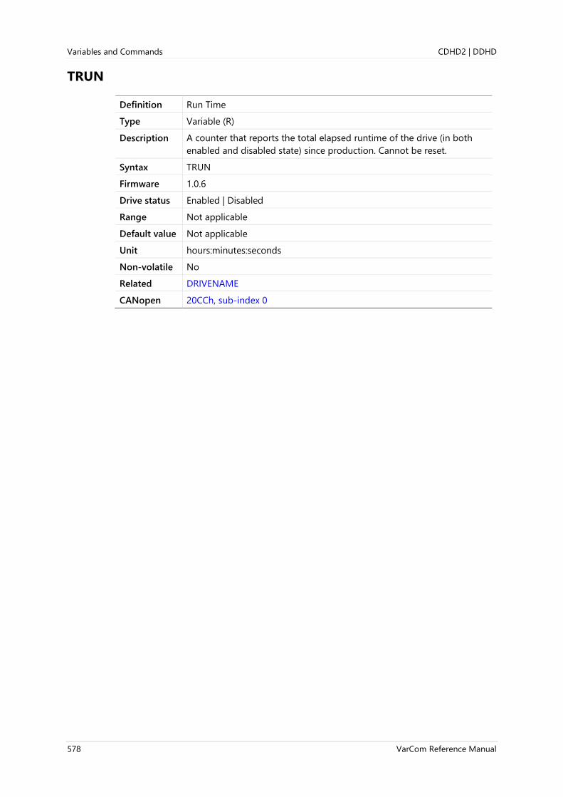
Variables and Commands CDHD2 | DDHD
578 VarCom Reference Manual
TRUN
Definition Run Time
Type Variable (R)
Description A counter that reports the total elapsed runtime of the drive (in both
enabled and disabled state) since production. Cannot be reset.
Syntax TRUN
Firmware 1.0.6
Drive status Enabled | Disabled
Range Not applicable
Default value Not applicable
Unit hours:minutes:seconds
Non-volatile No
Related DRIVENAME
CANopen 20CCh, sub-index 0

CDHD2 | DDHD Variables and Commands
VarCom Reference Manual 579
UNITSLINACC
Definition Units Linear Acc/Dec
Type Variable (R/W)
Description Gets/sets a value that defines the units of acceleration and deceleration
variables in a linear system.
Syntax Read: UNITSLINACC
Write: UNITSLINACC <value>
Firmware 1.0.6
Drive status Enabled | Disabled
Range 1 = mm/s2
Default value 1
Unit Not applicable
Non-volatile Yes
Related MOTORTYPE
UNITSLINPOS
UNITSLINVEL
UNITSROTACC
EtherCAT
CANopen
2117h, sub-index 0
Panel P 0 0 2 6

Variables and Commands CDHD2 | DDHD
580 VarCom Reference Manual
UNITSLINPOS
Definition Units Linear Position
Type Variable (R/W)
Description Gets/sets a value that defines the units of position variables in a linear
system.
Syntax Read: UNITSLINPOS
Write: UNITSLINPOS <value>
Firmware 1.0.6
Drive status Enabled | Disabled
Range 0 = pitch (motor cycles)
1 = count (pulses per revolution - PPR lines)
3 = mm
Default value 1
Unit Not applicable
Non-volatile Yes
Related MOTORTYPE
UNITSLINACC
UNITSLINVEL
UNITSROTPOS
EtherCAT
CANopen
2118h, sub-index 0
Panel P 0 0 2 5

CDHD2 | DDHD Variables and Commands
VarCom Reference Manual 581
UNITSLINVEL
Definition Units Linear Velocity
Type Variable (R/W)
Description Gets/sets a value that defines the units of velocity variables in a linear
system.
Syntax Read: UNITSLINVEL
Write: UNITSLINVEL <value>
Firmware 1.0.6
Drive status Enabled | Disabled
Range 1 = mm/s
Default value 1
Unit Not applicable
Non-volatile Yes
Related MOTORTYPE
UNITSLINACC
UNITSLINPOS
UNITSROTVEL
EtherCAT
CANopen
2119h, sub-index 0
Panel P 0 0 2 7

Variables and Commands CDHD2 | DDHD
582 VarCom Reference Manual
UNITSROTACC
Definition Units Rotary Acc/Dec
Type Variable (R/W)
Description Gets/sets a value that defines the units of acceleration and deceleration
variables in a rotary system.
Syntax Read: UNITSROTACC
Write: UNITSROTACC <value>
Firmware 1.0.6
Drive status Enabled | Disabled
Range 0 = rps/s
1 = rpm/s
2 = deg/s2
Default value 1
Unit Not applicable
Non-volatile Yes
Related ACC
DEC
DECSTOP
UNITSROTPOS
UNITSROTVEL
EtherCAT
CANopen
211Ah, sub-index 0
Panel P 0 0 2 3
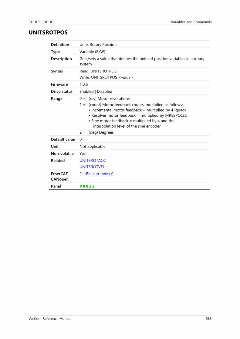
CDHD2 | DDHD Variables and Commands
VarCom Reference Manual 583
UNITSROTPOS
Definition Units Rotary Position
Type Variable (R/W)
Description Gets/sets a value that defines the units of position variables in a rotary
system.
Syntax Read: UNITSROTPOS
Write: UNITSROTPOS <value>
Firmware 1.0.6
Drive status Enabled | Disabled
Range 0 = (rev) Motor revolutions
1 = (count) Motor feedback counts, multiplied as follows:
• Incremental motor feedback = multiplied by 4 (quad)
• Resolver motor feedback = multiplied by MRESPOLES
• Sine motor feedback = multiplied by 4 and the
interpolation level of the sine encoder
2 = (deg) Degrees
Default value 0
Unit Not applicable
Non-volatile Yes
Related UNITSROTACC
UNITSROTVEL
EtherCAT
CANopen
211Bh, sub-index 0
Panel P 0 0 2 2
Variables and Commands CDHD2 | DDHD
584 VarCom Reference Manual
UNITSROTVEL
Definition Units Rotary Velocity
Type Variable (R/W)
Description Gets/sets a value that defines the units of velocity variables in a rotary
system.
Syntax Read: UNITSROTVEL
Write: UNITSROTVEL <value>
Firmware 1.0.6
Drive status Enabled | Disabled
Range 0 = rps
1 = rpm
2 = deg/s
Default value 1
Unit Not applicable
Non-volatile Yes
Related UNITSROTACC
UNITSROTPOS
V
VCMD
EtherCAT
CANopen
211Ch, sub-index 0
Panel P 0 0 2 4

CDHD2 | DDHD Variables and Commands
VarCom Reference Manual 585
USERPARAM
Definition User Parameter
Type Variable (R/W)
Description Parameter intended for use by firmware developers.
Syntax Read: USERPARAM
Write: USERPARAM <value>
Firmware 2.0.x
Drive status Enabled | Disabled
Range 0 to 4294967295
Default value 0
Unit Not applicable
Non-volatile Yes
Related
EtherCAT
CANopen
21ACh, sub-index 0

Variables and Commands CDHD2 | DDHD
586 VarCom Reference Manual
UVMODE
Definition Under-Voltage Mode
Type Variable (R/W)
Description Gets/sets a value that defines how the drive will respond to an under-
voltage condition.
Syntax Read: UVMODE
Write: UVMODE <value>
Firmware 1.0.6
Drive status Enabled | Disabled
Range 0 = Latches fault immediately if drive disabled or enabled.
1 = Issues warning if drive enabled. Ignores if drive disabled.
2 = Issues warning if drive enabled, then waits UVTIME before latching
the fault. Ignores if drive disabled.
3 = Issues warning if drive disabled. Latches fault immediately if drive
enabled.
Default value 0
Unit Not applicable
Non-volatile Yes
Related UVRECOVER
UVTHRESH
UVTIME
VBUS
VBUSREADOUT
EtherCAT
CANopen
20CDh, sub-index 0
Panel P 7 3 0 0

CDHD2 | DDHD Variables and Commands
VarCom Reference Manual 587
UVRECOVER
Definition Under-Voltage Recovery Mode
Type Variable (R/W)
Description Gets/sets a value that defines how the drive will recover from an under-
voltage fault.
Syntax Read: UVRECOVER
Write: UVRECOVER <value>
Firmware 1.0.6
Drive status Enabled | Disabled
Range 0 = Recovers by toggling drive from disable to enable condition after
the under-voltage condition clears.
1 = Automatically recovers when the under-voltage condition clears.
Default value 0
Unit Not applicable
Non-volatile Yes
Related UVMODE
UVTHRESH
UVTIME
VBUS
VBUSREADOUT
EtherCAT
CANopen
20CEh, sub-index 0
Panel P 7 3 0 1
Variables and Commands CDHD2 | DDHD
588 VarCom Reference Manual
UVTHRESH
Definition Under-Voltage Threshold
Type Variable (R/W)
Description Gets/set the level for detection of an under-voltage condition.
Syntax Read: UVTHRESH
Write: UVTHRESH <value>
Firmware 1.0.6
Drive status Enabled | Disabled
Range MV models: 90 – 400
LV models: 20 - 90
Default value Hardware-dependent
Unit V
Non-volatile Yes
Related UVMODE
UVRECOVER
UVTIME
VBUS
VBUSREADOUT
EtherCAT
CANopen
20CFh, sub-index 0
Panel P 7 3 0 2
CDHD2 | DDHD Variables and Commands
VarCom Reference Manual 589
UVTIME
Definition Under-Voltage Time
Type Variable (R/W)
Description Gets/sets the amount of time that an under-voltage warning will be
displayed ("u") before it is latched in UVMODE 2.
In UVMODE 3, the time begins when the drive is enabled.
Syntax Read: UVTIME
Write: UVTIME <value>
Firmware 1.0.6
Drive status Enabled | Disabled
Range 0 to 300
Default value 30
Unit second
Non-volatile Yes
Related UVMODE
UVRECOVER
UVTHRESH
VBUS
VBUSREADOUT
EtherCAT
CANopen
20D0h, sub-index 0
Panel P 7 3 0 3

Variables and Commands CDHD2 | DDHD
590 VarCom Reference Manual
V
Definition Velocity
Type Variable (R)
Description The velocity value measured by the feedback device (on motor or load),
according to SFBMODE.
Syntax V
Firmware 1.0.6
Drive status Enabled | Disabled
Range If MOTORTYPE 0 (Rotary): (231 -1) [rpm]
If MOTORTYPE 2 (Linear): (231 -1) [mm/s]
Default value Not applicable
Unit If MOTORTYPE 0 (Rotary):
If UNITSROTVEL 0 = rps
If UNITSROTVEL 1 = rpm
If UNITSROTVEL 2 = deg/s
If MOTORTYPE 2 (Linear):
UNITSLINVEL 1 = mm/s
Non-volatile No
Related UNITSROTVEL
VCMD
EtherCAT
CANopen
606Ch, sub-index 0
Panel d 0 0 0 0

CDHD2 | DDHD Variables and Commands
VarCom Reference Manual 591
VBUS
Definition Bus Voltage (DC)
Type Variable (R/W)
Description Gets/sets the drive bus voltage, used for current controller design.
VBUS also affects the value of VMAX.
When the value of VBUS is changed, CONFIG is required.
Syntax Read: VBUS
Write: VBUS <value>
Firmware 1.0.6
Drive status Disabled
Range 10 to 850
Default value 320
Unit V
Non-volatile Yes
Related OVTHRESH
UVMODE
UVTHRESH
VBUSREADOUT
EtherCAT
CANopen
20D1h, sub-index 0
Variables and Commands CDHD2 | DDHD
592 VarCom Reference Manual
VBUSREADOUT
Definition Bus Voltage Measured
Type Variable (R)
Description Indicates the bus voltage measured by sensors on the power module.
Syntax VBUSREADOUT
Firmware 1.0.6
Drive status Disabled
Range Hardware-defined
Default value Not applicable
Unit V
Non-volatile No
Related OVTHRESH
UVMODE
UVTHRESH
VBUS
EtherCAT
CANopen
6079h, sub-index 0
Panel P 0 0 1 3

CDHD2 | DDHD Variables and Commands
VarCom Reference Manual 593
VCMD
Definition Velocity Command
Type Variable (R)
Description Indicates the velocity command generated either directly (serial or
analog), or as the output of the position controller.
Syntax VCMD
Firmware 1.0.6
Drive status Enabled | Disabled
Range If MOTORTYPE 0 (Rotary): (231 -1) [rpm]
If MOTORTYPE 2 (Linear): (231 -1) [mm/s]
Default value Not applicable
Unit If MOTORTYPE 0 (Rotary):
If UNITSROTVEL 0 = rps
If UNITSROTVEL 1 = rpm
If UNITSROTVEL 2 = deg/s
If MOTORTYPE 2 (Linear):
UNITSLINVEL 1 = mm/s
Non-volatile No
Related OPMODE
UNITSROTVEL
V
EtherCAT
CANopen
606Bh, sub-index 0

Variables and Commands CDHD2 | DDHD
594 VarCom Reference Manual
VD
Definition Advanced Pole Placement D Polynomial
Type Variable (R/W)
Description Extended velocity controller D-polynomial.
Syntax Read: VD
Write: VD 0 0 0 0 0 0 0
Firmware 1.0.6
Drive status Enabled | Disabled
Range Not applicable
Default value 0 0 0 0 0 0 0 0
Unit Not applicable
Non-volatile Yes
Related VELCONTROLMODE
VF
VH
VR
EtherCAT
CANopen
2188h, sub-index 0
CDHD2 | DDHD Variables and Commands
VarCom Reference Manual 595
VE
Definition Velocity Error
Type Variable (R)
Description The velocity error of the velocity loop.
Syntax VE
Firmware 1.2.12
Drive status Enabled | Disabled
Range Not applicable
Default value Not applicable
Unit If MOTORTYPE 0 (Rotary):
If UNITSROTVEL 0 = rps
If UNITSROTVEL 1 = rpm
If UNITSROTVEL 2 = deg/s
If MOTORTYPE 2 (Linear):
UNITSLINVEL 1 = mm/s
Non-volatile No
Related V
VCMD
EtherCAT
CANopen
20D3h, sub-index 0

Variables and Commands CDHD2 | DDHD
596 VarCom Reference Manual
VELCMDMOVEAVG
Definition Velocity Command Moving Average Filter
Type Variable (R/W)
Description This command sets the moving average filter that is applied to the
velocity command value in OPMODE 0 and OPMODE 1.
The moving average filter is applied immediately after the ramp
generator.
Syntax Read: VELCMDMOVEAVG
Write: VELCMDMOVEAVG <value>
Firmware 1.40.0
Drive status Disabled
Range 0 to 255875
Default value 0
Unit µs (must be a multiple of 125)
Non-volatile Yes
Example --> VELCMDMOVEAVG
750
-->BAUDRATE 1125
-->
Related
EtherCAT
CANopen
Not applicable

CDHD2 | DDHD Variables and Commands
VarCom Reference Manual 597
VELCONTROLMODE
Definition Velocity Loop Controller
Type Variable (R/W)
Description Gets/sets a value that defines the type of velocity loop controller.
Syntax Read: VELCONTROMODE
Write: VELCONTROMODE <value>
Firmware 1.0.6
Drive status Disabled
Range 0 = PI controller (uses KVP, KVI)
1 = PDFF controller (uses KVP, KVI, KVFR)
2 = Standard pole placement controller (uses MJ, MKT, BW, LMJR, TF)
3 = Extended polynomial controller (uses VR, VD, VH, VF)
7 = HD velocity loop with integrator (uses KNLD, KNLP)
Note VELCONTROLMODE 7 provides the advantages of the HD nonlinear
controller for velocity control.
Use the Autotuning procedure to first tune the position loop, and then
switch to the velocity loop (VELCONTROLMODE 7)
Default value 7
Unit Not applicable
Non-volatile Yes
Related ICMD
IGRAV
VF
EtherCAT
CANopen
20D4h, sub-index 0
Panel P 1 0 0 1
Variables and Commands CDHD2 | DDHD
598 VarCom Reference Manual
VELCONTROLOUT
Definition Velocity Loop Controller Output
Type Variable (R)
Description Velocity loop controller output
Syntax VELCONTROLOUT
Firmware 1.4.4
Drive status Enabled | Disabled
Range Not applicable
Default value Not applicable
Unit A
Non-volatile No
Related VELFILTMODE
EtherCAT
CANopen
Not applicable

CDHD2 | DDHD Variables and Commands
VarCom Reference Manual 599
VELDESIGN
Definition Velocity Design Conversion
Type Command
Description Returns a conversion of the internal velocity controller as set by one of
the standard velocity control modes to a general extended polynomial
controller structure.
Note Applicable only to linear position controller (POSCONTROLMODE 0).
Syntax VELDESIGN
Firmware 1.0.6
Drive status Enabled | Disabled
Range Not applicable
Default value Not applicable
Unit Not applicable
Non-volatile Not applicable
Example -->veldesign
VD = 0 0 0 0 0 0 -1 0
VH = 0 0 0 0 0 0 0 0 0 0 0 0
VR = 0 0 0 0 0 0 0 0 0 0
VFI = 1073741824 0 0 30 0 0 0
VLIM = 1500.000
DIPEAK = 25.455
VRDHSCALE = 3000.000 25.455
VG = 1.000
Related FILTMODE
POSCONTROLMODE
VD
VELCONTROLMODE
VF
VH
VR
CANopen 20D5h, sub-index 0

Variables and Commands CDHD2 | DDHD
600 VarCom Reference Manual
VELFILTFRQ
Definition Velocity Filter Pole Frequency
Type Variable (R/W)
Description When VELFILTMODE=1, sets the first order filter, which is applied to the
velocity feedback signal before applying the velocity controller.
Syntax VELFILTFRQ <value>
Firmware 1.3.2
Drive status Disabled
Range 20 to 2000
Default value 440
Unit Hz
Non-volatile Yes
Related
EtherCAT
CANopen
211Dh, sub-index 0

CDHD2 | DDHD Variables and Commands
VarCom Reference Manual 601
VELFILTMODE
Definition Velocity Filter Mode
Type Variable (R/W)
Description Gets/sets the type of filter that is used for extraction of a velocity signal
from the position feedback.
Syntax Read: VELFILTMODE
Write: VELFILTMODE <value>
Firmware 1.0.6
Drive status Disabled
Range 0 = No filter
1 = First order filter
Default value 1
Unit Not applicable
Non-volatile Yes
Related FILTMODE
V
VELCONTROLMODE
EtherCAT
CANopen
20D6h, sub-index 0
Panel P 1 2 0 6

Variables and Commands CDHD2 | DDHD
602 VarCom Reference Manual
VEMAX
Definition Maximum Velocity Error
Type Variable (R/W)
Description Maximum velocity error value that does not produce a fault.
Syntax Read: VEMAX
Write: VEMAX <value>
Firmware 1.4.4
Drive status Enabled | Disabled
Range 0 to 6000 [rpm]
Default value 0
Unit If MOTORTYPE 0 (Rotary):
If UNITSROTVEL 0 = rps
If UNITSROTVEL 1 = rpm
If UNITSROTVEL 2 = deg/s
If MOTORTYPE 2 (Linear):
UNITSLINVEL 1 = mm/s
Non-volatile Yes
Related PEMAX
VLIM
EtherCAT
CANopen
Not applicable
CDHD2 | DDHD Variables and Commands
VarCom Reference Manual 603
VER
Definition Drive Version
Type Command
Syntax VER
Description Displays the firmware version.
Firmware 1.0.6
Drive status Enabled | Disabled
Range Not applicable
Default value Not applicable
Unit Not applicable
Non-volatile Not applicable
Example -->ver
Firmware Version: 2.0.0a0.0.48
FieldBus Version: EC_5.90.01
ESI Version : H00029001
FPGA Version : 4.08 March 16 2017
Resident Version: 1.3.4
-->
Related INFO
CANopen 20D7h, sub-index 1

Variables and Commands CDHD2 | DDHD
604 VarCom Reference Manual
VF
Definition Velocity Loop First Filter User Defined
Type Variable (R/W)
Description User defined polynomial velocity loop output filter.
Requires FILTMODE=6
Note This filter is applicable only in linear control mode and when
VELCONTROLMODE=3.
Syntax Read: VF
Write: VF 1 0 0 0 0 0 0
Firmware 1.0.6
Drive status Enabled | Disabled
Range Not applicable
Default value 1 0 0 0 0 0 0
Unit Not applicable
Non-volatile Yes
Related FILTMODE
VD
VELCONTROLMODE
VH
VR
EtherCAT
CANopen
20D8h, sub-index 1
CDHD2 | DDHD Variables and Commands
VarCom Reference Manual 605
VFEXT
Definition Velocity Loop Second Filter User Defined
Type Variable (R/W)
Description User defined polynomial velocity loop output filter.
Requires FILTEXTMODE=6
Note This filter is applicable only in linear control mode and when
VELCONTROLMODE=3.
Syntax Read: VFEXT
Write: VFEXT 1 0 0 0 0 0 0
Firmware 2.15.x
Drive status Enabled | Disabled
Range Not applicable
Default value 1 0 0 0 0 0 0
Unit Not applicable
Non-volatile Yes
Related FILTEXTMODE
VELCONTROLMODE
EtherCAT
CANopen
2214h, sub-index 0
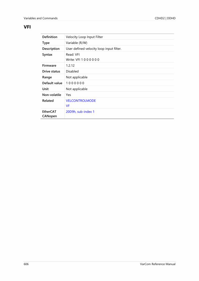
Variables and Commands CDHD2 | DDHD
606 VarCom Reference Manual
VFI
Definition Velocity Loop Input Filter
Type Variable (R/W)
Description User defined velocity loop input filter.
Syntax Read: VFI
Write: VFI 1 0 0 0 0 0 0
Firmware 1.2.12
Drive status Disabled
Range Not applicable
Default value 1 0 0 0 0 0 0
Unit Not applicable
Non-volatile Yes
Related VELCONTROLMODE
VF
EtherCAT
CANopen
20D9h, sub-index 1
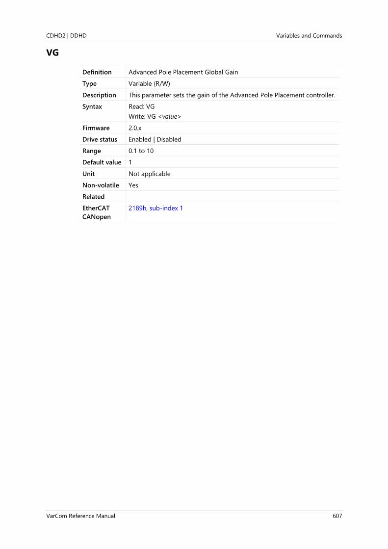
CDHD2 | DDHD Variables and Commands
VarCom Reference Manual 607
VG
Definition Advanced Pole Placement Global Gain
Type Variable (R/W)
Description This parameter sets the gain of the Advanced Pole Placement controller.
Syntax Read: VG
Write: VG <value>
Firmware 2.0.x
Drive status Enabled | Disabled
Range 0.1 to 10
Default value 1
Unit Not applicable
Non-volatile Yes
Related
EtherCAT
CANopen
2189h, sub-index 1

Variables and Commands CDHD2 | DDHD
608 VarCom Reference Manual
VH
Definition Advanced Pole Placement H Polynomial
Type Variable (R/W)
Description Extended velocity controller H-polynomial.
Syntax Read: VH
Write: VH 0 0 0 0 0 0 0 0 0 0 0 0
Firmware 1.0.6
Drive status Enabled | Disabled
Range Not applicable
Default value 0 0 0 0 0 0 0 0 0 0 0 0
Unit Not applicable
Non-volatile Yes
Related VD
VELCONTROLMODE
VF
VR
EtherCAT
CANopen
20DAh, sub-index 1

CDHD2 | DDHD Variables and Commands
VarCom Reference Manual 609
VINT
Definition Velocity Internal
Type Variable (R)
Description The raw (unfiltered) internal velocity measurement in the drive.
Used by the identification procedure (IDENT).
Syntax VINT
Firmware 2.0.x
Drive status Enabled | Disabled
Range Not applicable
Default value Not applicable
Unit Not applicable
Non-volatile No
Related IDENT
EtherCAT
CANopen
Not applicable
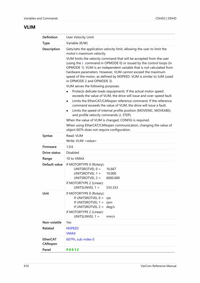
Variables and Commands CDHD2 | DDHD
610 VarCom Reference Manual
VLIM
Definition User Velocity Limit
Type Variable (R/W)
Description Gets/sets the application velocity limit, allowing the user to limit the
motor’s maximum velocity.
VLIM limits the velocity command that will be accepted from the user
(using the J command in OPMODE 0) or issued by the control loops (in
OPMODE 1). VLIM is an independent variable that is not calculated from
hardware parameters. However, VLIM cannot exceed the maximum
speed of the motor, as defined by MSPEED. VLIM is similar to ILIM (used
in OPMODE 2 and OPMODE 3).
VLIM serves the following purposes:
⚫ Protects delicate loads (equipment). If the actual motor speed
exceeds the value of VLIM, the drive will issue and over-speed fault.
⚫ Limits the EtherCAT/CANopen reference command. If the reference
command exceeds the value of VLIM, the drive will issue a fault.
⚫ Limits the speed of internal profile position (MOVEINC, MOVEABS)
and profile velocity commands (J, STEP).
When the value of VLIM is changed, CONFIG is required.
When using EtherCAT/CANopen communication, changing the value of
object 607h does not require configuration.
Syntax Read: VLIM
Write: VLIM <value>
Firmware 1.0.6
Drive status Disabled
Range 10 to VMAX
Default value If MOTORTYPE 0 (Rotary):
UNITSROTVEL 0 = 16.667
UNITSROTVEL 1 = 10.000
UNITSROTVEL 2 = 6000.000
If MOTORTYPE 2 (Linear):
UNITSLINVEL 1 = 533.333
Unit If MOTORTYPE 0 (Rotary):
If UNITSROTVEL 0 = rps
If UNITSROTVEL 1 = rpm
If UNITSROTVEL 2 = deg/s
If MOTORTYPE 2 (Linear):
UNITSLINVEL 1 = mm/s
Non-volatile Yes
Related MSPEED
VMAX
EtherCAT
CANopen
607Fh, sub-index 0
Panel P 0 0 1 2

CDHD2 | DDHD Variables and Commands
VarCom Reference Manual 611
VMAX
Definition Maximum Velocity for Motor and Drive
Type Variable (R)
Description Displays the maximum velocity for a drive and motor combination.
VMAX is based on maximum motor speed.
Syntax VMAX
Firmware 1.0.6
Drive status Enabled | Disabled
Range 10 to MSPEED
Default value If MOTORTYPE 0 (Rotary):
UNITSROTVEL 0 = 161.166
UNITSROTVEL 1 = 9669.946
UNITSROTVEL 2 = 58019.675
If MOTORTYPE 2 (Linear):
UNITSLINVEL 1 = 5157.304
Unit If MOTORTYPE 0 (Rotary):
If UNITSROTVEL 0 = rps
If UNITSROTVEL 1 = rpm
If UNITSROTVEL 2 = deg/s
If MOTORTYPE 2 (Linear):
UNITSLINVEL 1 = mm/s
Non-volatile No
Related MKT
MSPEED
VBUSVLIM
EtherCAT
CANopen
20EEh, sub-index 0

Variables and Commands CDHD2 | DDHD
612 VarCom Reference Manual
VR
Definition Advanced Pole Placement R Polynomial
Type Variable (R/W)
Description Extended velocity controller R-polynomial.
Syntax Read: VR
Write: VR 0 0 0 0 0 0 0 0 0 0
Firmware 1.0.6
Drive status Disabled
Range Not applicable
Default value 0 0 0 0 0 0 0 0 0 0
Unit Not applicable
Non-volatile Yes
Related VELCONTROLMODE
EtherCAT
CANopen
20DBh, sub-index 1

CDHD2 | DDHD Variables and Commands
VarCom Reference Manual 613
WNSERR
Definition Wake No Shake Status
Type Variable (R)
Description PHASEFINDMODE 2 state.
Syntax WNSERR
Firmware 1.0.6
Drive status Enabled | Disabled
Range Not applicable
Default value Not applicable
Unit Not applicable
Non-volatile No
Related PHASEFIND
PHASEFINDMODE
PHASEFINDST
CANopen 20DCh, sub-index 0

Variables and Commands CDHD2 | DDHD
614 VarCom Reference Manual
WRN
Definition Display Warnings
Type Command
Description Lists the warnings that have occurred since the buffer was last cleared.
Syntax WRN
Firmware 1.0.6
Drive status Enabled | Disabled
Range Not applicable
Default value Not applicable
Unit Not applicable
Non-volatile Not applicable
Example -->wrn
WRN 7 Encoder init: Halls switch not found
WRN 8 Encoder init: Index not detected
-->
Related FLT
FLTHIST
CANopen 20DDh, sub-index 0

CDHD2 | DDHD Variables and Commands
VarCom Reference Manual 615
XENCRES
Definition External Encoder Resolution
Type Variable (R/W)
Description Gets/sets the resolution of the external encoder, in number of pulses
per motor revolution.
For sine encoder, gets/sets the number of sine cycles per motor
revolution.
Syntax Read: XENCRES
Write: XENCRES <value>
Firmware 1.0.6
Drive status Disabled
Range 100 to 10000000
Default value 2048
Unit MOTORTYPE=0 (Rotary): lines per revolution (LPR)
MOTORTYPE=2 (Linear): lines per pitch (LPP)
Non-volatile Yes
Related GEARIN
GEARMODE
GEAROUT
EtherCAT
CANopen
20DEh, sub-index 0
Panel P 0 0 0 4

Variables and Commands CDHD2 | DDHD
616 VarCom Reference Manual
ZERO
Definition Zeroing Command
Type Command
Description Activates Zeroing mode, which locks the rotor in place by passing a
fixed current through two phases. This is useful for determining the
commutation offset (MPHASE) on motors that have a resolver or
absolute encoder.
When Zeroing is activated, the drive rotates and locks the motor at the
fixed electrical angle with a fixed current (IZERO). Locking occurs after
stopping briefly at a temporary location to overcome static friction or
after starting at an electrical angle 180° away from the final locked
position.
The number of motor electrical cycles per one mechanical revolution is
equal to the number of pairs of magnets. Each pair of magnets in the
motor creates a 0—360 degree electrical cycle. Therefore, if the motor
has 8 individual magnetic poles (MPOLES), the motor can be locked at
four different places in one mechanical revolution.
After the motor has locked (meaning it is in a position at which PE is
less than PEINPOS), ZEROST returns a suggested MPHASE value
according to the procedure, but does not automatically set it.
Syntax ZERO {0|1}
Firmware 1.0.6
Drive status Disabled
Range 0 = Zeroing not activated
1 = Zeroing activated
Default value 0
Unit Not applicable
Non-volatile Not applicable
Example -->k
-->zero 1
-->en
-->zerost
Zero Ended, MPHASE = 28
-->k
-->mphase 28
-->en
Related FEEDBACKTYPE
IZERO
MPHASE
MPOLES
PHASEFIND
ZEROST
EtherCAT
CANopen
20DF, sub-index 0

CDHD2 | DDHD Variables and Commands
VarCom Reference Manual 617
ZEROST
Definition Zeroing MPHASE Value
Type Variable (R)
Description After running ZERO command, querying ZEROST returns the value of
MPHASE that should be set for proper commutation.
This may be useful when MOTORSETUP is unsuccessful. The accuracy of
the commutation which is initialized this way depends on the load and
friction of the system.
Syntax ZEROST
Firmware 1.4.4
Drive status Enabled
Range Not applicable
Default value Not applicable
Unit Electrical degree
Non-volatile No
Related MOTORSETUP
MPHASE
ZERO
EtherCAT
CANopen
217Bh, sub-index 0

Serial Communication CDHD2 | DDHD
618 VarCom Reference Manual
4 Serial Communication
Serial Communication Overview
The serial communication link enables communication between the drive and host (terminal,
PC, or high-level controller) using ASCII-coded messages transmitted over an asynchronous,
multi-drop line.
When the host and drive communicate through serial communication, a proprietary set of
commands and variables, called VarCom, are used to configure, control and monitor the
drive.
The communication interface can be a graphical software interface, such as ServoStudio, or a
user-designed application, or a basic terminal.
This chapter describes the serial communication protocol used by the drive and its host.
Serial Communication Specifications
Communications port RS232, USB
Baud rate 115200 bits per second (bps)
Start bits 1
Data bits 8
Stop bits 1
Parity None
Hardware handshake None
Software handshake None
Character ASCII code
Data error check 8-bit checksum
Control Code Definitions
Name Symbol Hex
Line feed <LF> 0Ah
Carriage return <CR> 0Dh
Space <SP> 20h
Delay <DLY> Indicates delay due to internal drive
processing of information
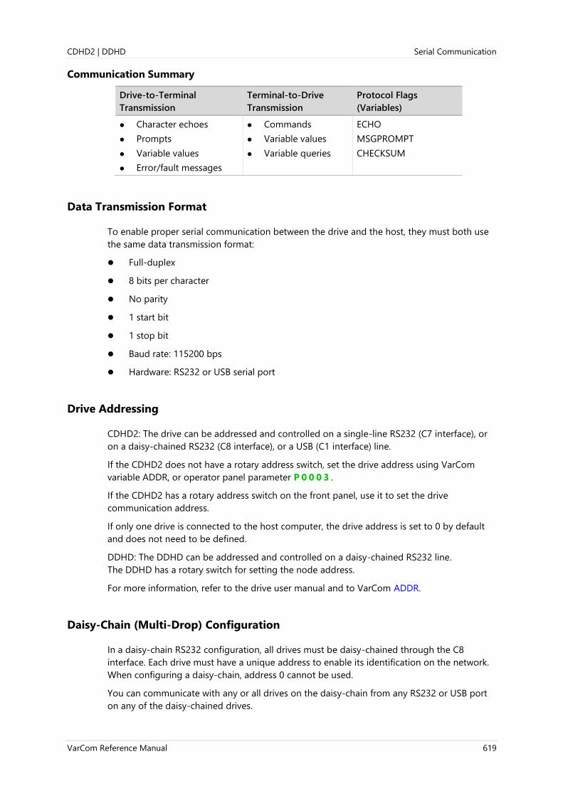
CDHD2 | DDHD Serial Communication
VarCom Reference Manual 619
Communication Summary
Drive-to-Terminal
Transmission
Terminal-to-Drive
Transmission
Protocol Flags
(Variables)
⚫ Character echoes
⚫ Prompts
⚫ Variable values
⚫ Error/fault messages
⚫ Commands
⚫ Variable values
⚫ Variable queries
ECHO
MSGPROMPT
CHECKSUM
Data Transmission Format
To enable proper serial communication between the drive and the host, they must both use
the same data transmission format:
⚫ Full-duplex
⚫ 8 bits per character
⚫ No parity
⚫ 1 start bit
⚫ 1 stop bit
⚫ Baud rate: 115200 bps
⚫ Hardware: RS232 or USB serial port
Drive Addressing
CDHD2: The drive can be addressed and controlled on a single-line RS232 (C7 interface), or
on a daisy-chained RS232 (C8 interface), or a USB (C1 interface) line.
If the CDHD2 does not have a rotary address switch, set the drive address using VarCom
variable ADDR, or operator panel parameter P 0 0 0 3 .
If the CDHD2 has a rotary address switch on the front panel, use it to set the drive
communication address.
If only one drive is connected to the host computer, the drive address is set to 0 by default
and does not need to be defined.
DDHD: The DDHD can be addressed and controlled on a daisy-chained RS232 line.
The DDHD has a rotary switch for setting the node address.
For more information, refer to the drive user manual and to VarCom ADDR.
Daisy-Chain (Multi-Drop) Configuration
In a daisy-chain RS232 configuration, all drives must be daisy-chained through the C8
interface. Each drive must have a unique address to enable its identification on the network.
When configuring a daisy-chain, address 0 cannot be used.
You can communicate with any or all drives on the daisy-chain from any RS232 or USB port
on any of the daisy-chained drives.

Serial Communication CDHD2 | DDHD
620 VarCom Reference Manual
⚫ To communicate with an individual drive in a daisy-chain, enter the following at the
prompt:
\x <Enter>
Where x = the address setting of the drive.
⚫ To communicate simultaneously with all drives on the chain, enter the following at the
prompt:
\* <Enter>
This is called global addressing. When using global addressing, no character echo to the
terminal occurs.
Serial Variables and Commands
When the host and drive are communicating through a serial connection, VarCom is used to
configure, control and monitor the drive. The VarCom set of functions includes:
⚫ Commands: instruct the drive to perform an operation.
⚫ Read-only variables: calculated and/or set by the drive, and used to monitor the drive
and its operational status.
To read a variable, type the VarCom mnemonic followed by <Enter> (carriage return,
CR). The drive returns the value of the variable.
⚫ Read/Write variables: used to configure and monitor the drive.
To set a variable value, type the VarCom mnemonic, a space (or =), the value, and then
<Enter> (carriage return, CR).
Data Control
The drive can process approximately 16 characters per millisecond (at 115200 baud rate).
The operating system recognizes backspaces and resets upon receipt of an <Esc> character.
The following VarCom variables allow you to configure communication responses between
drive and host.
ECHO Enables/disables the serial port character echo. If echo is enabled,
characters received via the serial port are echoed back to the serial port
and displayed on the computer monitor.
ECHO 0 = Serial port echo disabled
ECHO 1 = Serial port echo enabled
ECHO allows the host to check the validity of the information received
by the drive.
MSGPROMPT Defines whether asynchronous messages and the prompt from the drive
are sent to the serial port (and to the host computer)
0 = Messages and prompt disabled
1 = Messages and prompt enabled
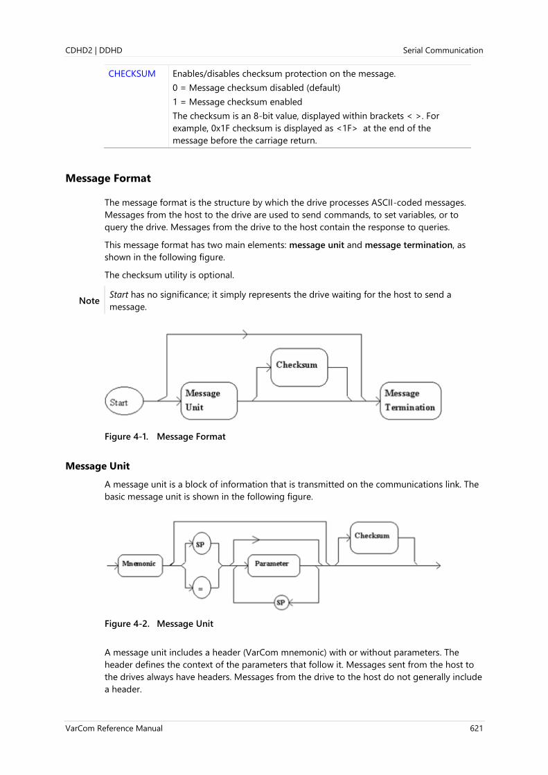
CDHD2 | DDHD Serial Communication
VarCom Reference Manual 621
CHECKSUM Enables/disables checksum protection on the message.
0 = Message checksum disabled (default)
1 = Message checksum enabled
The checksum is an 8-bit value, displayed within brackets < >. For
example, 0x1F checksum is displayed as <1F> at the end of the
message before the carriage return.
Message Format
The message format is the structure by which the drive processes ASCII-coded messages.
Messages from the host to the drive are used to send commands, to set variables, or to
query the drive. Messages from the drive to the host contain the response to queries.
This message format has two main elements: message unit and message termination, as
shown in the following figure.
The checksum utility is optional.
Note Start has no significance; it simply represents the drive waiting for the host to send a
message.
Figure 4-1. Message Format
Message Unit
A message unit is a block of information that is transmitted on the communications link. The
basic message unit is shown in the following figure.
Figure 4-2. Message Unit
A message unit includes a header (VarCom mnemonic) with or without parameters. The
header defines the context of the parameters that follow it. Messages sent from the host to
the drives always have headers. Messages from the drive to the host do not generally include
a header.

Serial Communication CDHD2 | DDHD
622 VarCom Reference Manual
When used, parameters are separated from the mnemonic by either a space or an
assignment operator. Parameters must be separated by spaces.
The drive can receive only a single message unit in a message format.
Message Termination
Message termination refers to the end of the message being sent.
Messages transmitted by the host are terminated by a carriage return (CR) – ASCII character
0DH.
Figure 4-3. Host Message Termination Format
Messages transmitted by the drive are terminated by a carriage return/line feed (CR/LF)
combination – ASCII characters 0DH/0AH.
Figure 4-4. Drive Message Termination Format
The drive also accepts a message termination sent without any additional information.
Complete Message Format with Checksum
The CHECKSUM block is used only when CHECKSUM command is set.
The drive is configured to accept incoming messages with or without checksum, and to
append checksum to outgoing message according to the CHECKSUM variable.
Checksum is represented by two ASCII digits within brackets <> preceding the <CR>.
The complete message format is shown in the following figure.
Figure 4-5. Complete Message Format

CDHD2 | DDHD Serial Communication
VarCom Reference Manual 623
Units
Within a message or command, units are enclosed in brackets [ ]. For example:
⚫ Message to drive: MPOLES
⚫ Message from drive: 4 [poles]
When a command from the host contains units, the drive ignores the unit information.
Asynchronous Error Messages
The asynchronous error message function is enabled by the variable MSGPROMPT.
⚫ If this function is enabled, and an error or fault occurs, the drive transmits a brief error
message to the host.
⚫ If the function is disabled, the error message is transmitted after a <CR> message
termination is detected by the drive. This occurs whenever the host sends a message to
the drive.
The variable MSGPROMPT also controls the prompt sent by the drive at the end of a
message.
⚫ If echoing is enabled, the characters in the message are all echoed before the error
message is transmitted. Even though an error has occurred and its message returned to
the host, the drive still accepts new incoming messages and attempts to execute them.
⚫ If echoing is disabled, the error message is transmitted after the <CR> message
termination is detected by the drive.
The drive must detect a new error or fault before transmitting an error message.
Examples of Serial Protocol
The following examples demonstrate serial protocol between the drive and a host.
Issuing a Command or Variable
In Examples 1 through 5, drive parameters are defined as:
ADDR 0
CHECKSUM 0
ECHO 1
MSGPROMPT 1
Example 1 – Command
EN (drive enable)
Sequence # 1 2 3 4 5 6 7 8 9 10 11
User Enters E N <CR>
Drive Returns E N <CR> <LF> <DLY> - - >

Serial Communication CDHD2 | DDHD
624 VarCom Reference Manual
Displayed on terminal:
-->EN
-->
Example 2 – Command/Variable – Returns Multiple Lines of Values
This type of command typically has a longer delay due to the large amount of data that is
output to the screen.
DUMP (return drive parameter values)
Sequence # 1 2 3 4 5 6 7 8 9 10
User Enters D U M P <CR>
Drive Returns D U M P <CR>
Sequence # 11 12 13 14 15 16 17 18
User Enters
Drive Returns <LF> <DLY> <VAR1> <SP> <VAL1> <CR> <LF> <VAR2>
Sequence # 19 20 21 22 23 24 25 26
User Enters
Drive Returns <SP> <VAL2> <CR> <LF> <VARn> <SP> <VALn> <LF>
Sequence # 27 28 29 30
User Enters
Drive Returns <CR> - - >
Displayed on terminal:
-->DUMP
-->var1 val1
-->var2 val2
-->varn valn
Example 3 – Command/Variable – Returns Multiple Values
J (jog)
Sequence # 1 2 3 4 5 6 7 8 9 10
User Enters J <CR>
Drive Returns J <CR> <LF> <DLY> <VAL1> <SP> <VAL2> <CR>
Sequence # 11 12 13 14
User Enters
Drive Returns <LF> - - >

CDHD2 | DDHD Serial Communication
VarCom Reference Manual 625
Displayed on terminal:
-->J
-->nnnnn
-->
Example 4 – Reading a Variable Value
MPOLES (single pole motor with value 2)
Sequence # 1 2 3 4 5 6 7 8 9 10
User Enters M P O L E
Drive Returns M P O L E
Sequence # 11 12 13 14 15 16 17 18 19 20
User Enters S <CR>
Drive Returns S <CR> <LF> <DLY> 2 <SP> [ p
Sequence # 21 22 23 24 25 26 27 28 29 30 31
User Enters
Drive Returns o l e s ] <CR> <LF> <DLY> - - >
Displayed on terminal:
-->MPOLES
2 [poles]
-->
Example 5 – Defining a Variable Value
ACC (acceleration with value 50000)
Sequence # 1 2 3 4 5 6 7 8 9 10
User Enters A C C = 5
Drive Returns A C C = 5
Sequence # 11 12 13 14 15 16 17 18 19 20
User Enters 0 0 0 0 <CR>
Drive Returns 0 0 0 0 <CR>
Sequence # 21 22 23 24 25
User Enters
Drive Returns <LF> <DLY> - - >
Displayed on terminal:
-->ACC=50000
-->

Serial Communication CDHD2 | DDHD
626 VarCom Reference Manual
Multi-Drop Mode
In Examples 6 and 7, drive parameter values are defined as:
ADDR 3
ECHO 1
MSGPROMPT 1
Example 6 – Addressing a Daisy-Chained Drive
The range of values for ADDR is 0 to 99. A value other than 0 puts the system in
Multi-drop mode, which results in a different prompt.
Sequence # 1 2 3 4 5 6 7 8 9 10 11
User Enters \ 3 <CR>
Drive Returns \ 3 <CR> <LF> <DLY> 3 - >
Displayed on terminal:
-->\3
3->
Example 7 – Reading a Variable
IMAX (drive current limit)
Sequence # 1 2 3 4 5 6 7 8 9 10
User Enters I M A X <CR>
Drive Returns I M A X <CR>
Sequence # 11 12 13 14 15 16 17 18 19 20
User Enters
Drive Returns <LF> 1 5 . 6 9 7 <CR> <LF> <DLY>
Sequence # 21 22 23
User Enters
Drive Returns 3 - >
Displayed on terminal:
-->IMAX
3->15.697
3->
Serial Checksum
Example 8 – Variable
In this example, drive parameters are defined as:
ADDR 0
CHECKSUM 1

CDHD2 | DDHD Serial Communication
VarCom Reference Manual 627
ECHO 1
MSGPROMPT 1
ACC (acceleration) with value 25000
Sequence # 1 2 3 4 5 6 7 8 9 10
User Enters A C C = 2
Drive Returns A C C = 2
Sequence # 11 12 13 14 15 16 17 18 19 20
User Enters 5 0 0 0 <
Drive Returns 5 0 0 0 <
Sequence # 21 22 23 24 25 26 27 28 29 30 31
User Enters F B > <CR>
Drive Returns F B > <CR> - - >
Character Hex Value ASCII Value
A 41 65
C 43 67
C 43 67
= 3D 61
2 32 50
5 35 53
0 30 48
0 30 48
0 30 48
Checksum=0xFF& (0x41+0x43+0x43+0x3d+0x32+0x35+0x30+0x30+0x30)
=0xFF & 0x01FB=0xFB
Note Enter the last two characters of the hex value sum before the <CR>, between brackets < >
Displayed on terminal:
//setting the checksum
-->CHECKSUM 1
//sending command to the drive with checksum appended
-->ACC=25000<FB>
//checking the actual value stored at the drive
-->ACC
//the reply is appended by checksum
25000.000[rpm/s]<7E>
-->

VarCom Reference Manual
for CDHD2 and DDHD