vapor recovery equipment defects list - california air … · · 2017-01-20vapor recovery...
TRANSCRIPT
Vapor Recovery Equipment Defects List
Adopted: September 23, 2002 Amended: June 22, 2005 Amended: June 17, 2008 Amended: June 11, 2012
Amended: September 9, 2016
Vapor Recovery Equipment Defects List (VRED List) Date of Issuance: January 1, 2017
California Air Resources Board Page 1 of 24 VRED List – Amended on: September 9, 2016
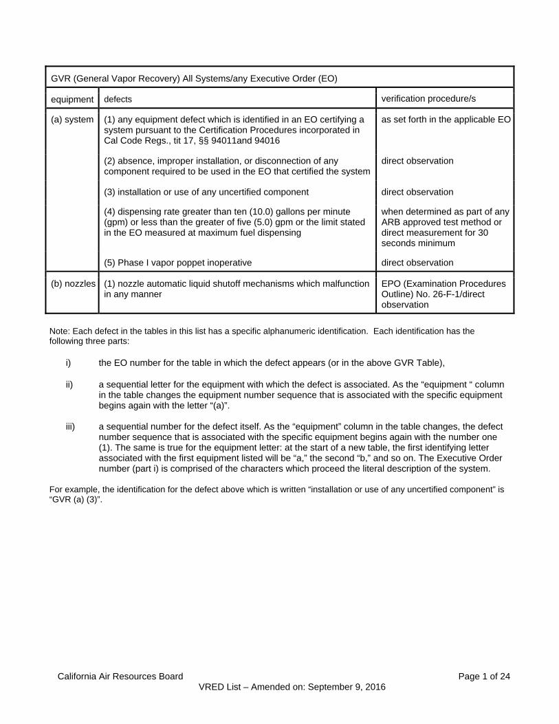
GVR (General Vapor Recovery) All Systems/any Executive Order (EO)
equipment defects verification procedure/s
(a) system (1) any equipment defect which is identified in an EO certifying a system pursuant to the Certification Procedures incorporated in Cal Code Regs., tit 17, §§ 94011and 94016
as set forth in the applicable EO
(2) absence, improper installation, or disconnection of any component required to be used in the EO that certified the system
direct observation
(3) installation or use of any uncertified component direct observation
(4) dispensing rate greater than ten (10.0) gallons per minute (gpm) or less than the greater of five (5.0) gpm or the limit stated in the EO measured at maximum fuel dispensing
when determined as part of any ARB approved test method or direct measurement for 30 seconds minimum
(5) Phase I vapor poppet inoperative direct observation
(b) nozzles (1) nozzle automatic liquid shutoff mechanisms which malfunction in any manner
EPO (Examination Procedures Outline) No. 26-F-1/direct observation
Note: Each defect in the tables in this list has a specific alphanumeric identification. Each identification has the following three parts:
i) the EO number for the table in which the defect appears (or in the above GVR Table), ii) a sequential letter for the equipment with which the defect is associated. As the “equipment “ column
in the table changes the equipment number sequence that is associated with the specific equipment begins again with the letter “(a)”.
iii) a sequential number for the defect itself. As the “equipment” column in the table changes, the defect number sequence that is associated with the specific equipment begins again with the number one (1). The same is true for the equipment letter: at the start of a new table, the first identifying letter associated with the first equipment listed will be “a,” the second “b,” and so on. The Executive Order number (part i) is comprised of the characters which proceed the literal description of the system.
For example, the identification for the defect above which is written “installation or use of any uncertified component” is “GVR (a) (3)”.

California Air Resources Board Page 2 of 24 VRED List – Amended on: September 9, 2016
G-70-7 series Hasstech VCP-2 and VCP-2A AST (Aboveground Storage Tank) Only
equipment defects verification procedure
(a) system (1) any fueling point associated with a vapor line disconnected and open to the atmosphere, including all fueling points at the facility if vapor lines are manifolded
direct observation
(2) system not in compliance with the static pressure decay test criteria* TP (Test Procedure) 201.3 or equivalent
(3) any grade of a fueling point not capable of demonstrating an air to liquid ratio compliance with its performance standard
TP201.5 or equivalent
(4) pressure drop through the system exceeds one-half (0.50) inch water column at sixty cubic feet per hour (60 CFH)
TP201.4 or equivalent
(b) hoses (1) any coaxial hose with a perforation exceeding one-eighth (0.13) inch diameter
direct measurement/ observation
(2) any coaxial hose with slits or tears in excess of one-fourth (0.25) inch in length
direct measurement/ observation
(c) processing unit
(1) three consecutive unsuccessful attempts to ignite the incinerator which occur at least two hours after a bulk delivery *
direct measurement/ observation/system monitor observation
(2) unit does not activate when the system pressure reaches or exceeds two (2.0) inches water column and occurs at least two hours after a bulk delivery*
direct measurement using storage tank pressure device
(3) emissions which exceed Ringelmann one-half (½ ) or ten percent (10%) opacity and not attributable to a bulk delivery *
Method 9
(4) vapor processing unit inoperative * direct observation
(d) collection unit (1) vacuum producing device inoperative * direct observation
* when the identified defect is detected in the listed equipment, the defect determination applies to all affected interrelated systems (which may include all systems at the motor vehicle fueling operation).
California Air Resources Board Page 3 of 24 VRED List – Amended on: September 9, 2016
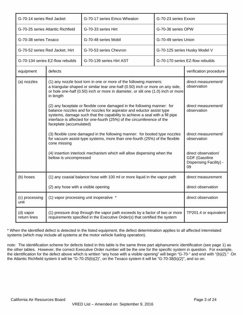
G-70-14 series Red Jacket G-70-17 series Emco Wheaton G-70-23 series Exxon
G-70-25 series Atlantic Richfield G-70-33 series Hirt G-70-36 series OPW
G-70-38 series Texaco G-70-48 series Mobil G-70-49 series Union
G-70-52 series Red Jacket, Hirt G-70-53 series Chevron G-70-125 series Husky Model V
G-70-134 series EZ-flow rebuilds G-70-139 series Hirt AST G-70-170 series EZ-flow rebuilds
equipment defects verification procedure
(a) nozzles (1) any nozzle boot torn in one or more of the following manners: a triangular-shaped or similar tear one-half (0.50) inch or more on any side, or hole one-half (0.50) inch or more in diameter, or slit one (1.0) inch or more in length
direct measurement/ observation
(2) any faceplate or flexible cone damaged in the following manner: for balance nozzles and for nozzles for aspirator and eductor assist type systems, damage such that the capability to achieve a seal with a fill pipe interface is affected for one-fourth (25%) of the circumference of the faceplate (accumulated)
direct measurement/ observation
(3) flexible cone damaged in the following manner: for booted type nozzles for vacuum assist-type systems, more than one-fourth (25%) of the flexible cone missing
direct measurement/ observation
(4) insertion interlock mechanism which will allow dispensing when the bellow is uncompressed
direct observation/ GDF (Gasoline Dispensing Facility) -09
(b) hoses (1) any coaxial balance hose with 100 ml or more liquid in the vapor path direct measurement
(2) any hose with a visible opening direct observation
(c) processing unit
(1) vapor processing unit inoperative * direct observation
(d) vapor return lines
(1) pressure drop through the vapor path exceeds by a factor of two or more requirements specified in the Executive Order(s) that certified the system
TP201.4 or equivalent
* When the identified defect is detected in the listed equipment, the defect determination applies to all affected interrelated systems (which may include all systems at the motor vehicle fueling operation). note: The identification scheme for defects listed in this table is the same three part alphanumeric identification (see page 1) as the other tables. However, the correct Executive Order number will be the one for the specific system in question. For example, the identification for the defect above which is written “any hose with a visible opening” will begin “G-70-“ and end with “(b)(2).” On the Atlantic Richfield system it will be “G-70-25(b)(2)”, on the Texaco system it will be “G-70-38(b)(2)”, and so on.
California Air Resources Board Page 4 of 24 VRED List – Amended on: September 9, 2016
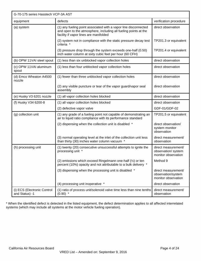
G-70-175 series Hasstech VCP-3A AST
equipment defects verification procedure
(a) system (1) any fueling point associated with a vapor line disconnected and open to the atmosphere, including all fueling points at the facility if vapor lines are manifolded
direct observation
(2) system not in compliance with the static pressure decay test criteria *
TP201.3 or equivalent
(3) pressure drop through the system exceeds one-half (0.50) inch water column at sixty cubic feet per hour (60 CFH)
TP201.4 or equivalent
(b) OPW 11VAI steel spout (1) less than six unblocked vapor collection holes direct observation
(c) OPW 11VAI aluminum spout
(1) less than four unblocked vapor collection holes direct observation
(d) Emco Wheaton A4500 nozzle
(1) fewer than three unblocked vapor collection holes direct observation
(2) any visible puncture or tear of the vapor guard/vapor seal assembly
direct observation
(e) Husky V3 6201 nozzle (1) all vapor collection holes blocked direct observation
(f) Husky V34 6200-8 (1) all vapor collection holes blocked direct observation
(2) defective vapor valve GDF-01/GDF-02
(g) collection unit (1) any grade of a fueling point not capable of demonstrating an air to liquid ratio compliance with its performance standard
TP201.5 or equivalent
(2) dispensing when the collection unit is disabled * direct observation/ system monitor observation
(3) normal operating level at the inlet of the collection unit less than thirty (30) inches water column vacuum *
direct measurement/ observation
(h) processing unit (1) twenty (20) consecutive unsuccessful attempts to ignite the processing unit *
direct measurement/ observation/ system monitor observation
(2) emissions which exceed Ringelmann one-half (½) or ten percent (10%) opacity and not attributable to a bulk delivery *
Method 9
(3) dispensing when the processing unit is disabled * direct measurement/ observation/system monitor observation
(4) processing unit inoperative * direct observation
(i) ECS (Electronic Control and Status) -1
(1) ratio of process unit/solenoid valve time less than nine tenths (0.90) *
direct measurement/ observation
* When the identified defect is detected in the listed equipment, the defect determination applies to all affected interrelated systems (which may include all systems at the motor vehicle fueling operation).

California Air Resources Board Page 5 of 24 VRED List – Amended on: September 9, 2016
G-70-177 series Hirt VCS400-7
equipment defects verification procedure
(a) system (1) any fueling point associated with a vapor line disconnected and open to the atmosphere, including all fueling points at the facility if vapor lines are manifolded
direct observation
(2) pressure drop through the system exceeds one-half (0.50) inch water column at sixty cubic feet per hour (60 CFH)
TP201.4 or equivalent
(3) any grade of a fueling point not capable of demonstrating an air to liquid ratio compliance with its performance standard
TP201.5 or equivalent
(4) processing unit inoperative * direct observation
(b) OPW 11VA-29 nozzle
(1) defective vapor valve GDF-01/GDF-02
(2) less than five unblocked vapor collection holes direct observation
(c) hoses (1) any visible puncture or tear equivalent to a diameter of 0.136 inches or greater
direct measurement/ observation
* When the identified defect is detected in the listed equipment, the defect determination applies to all affected interrelated systems (which may include all systems at the motor vehicle fueling operation).

California Air Resources Board Page 6 of 24 VRED List – Amended on: September 9, 2016
G-70-181 series Hirt VCS400-7 AGT (AST)
equipment defects verification procedure
(a) system (1) any fueling point associated with a vapor line disconnected and open to the atmosphere, including all fueling points at the facility if vapor lines are manifolded
direct observation
(2) pressure drop through the system exceeds one-half (0.50) inch water column at sixty cubic feet per hour (60 CFH)
TP201.4 or equivalent
(3) any grade of a fueling point not capable of demonstrating an air to liquid ratio compliance with its performance standard
TP201.5 or equivalent
(4) processing unit inoperative * direct observation
(b) OPW 11VA-29 nozzle
(1) defective vapor valve GDF-01/GDF-02
(2) less than five unblocked vapor collection holes direct observation
(c) hoses (1) any visible puncture or tear equivalent to a diameter of 0.136 inches or greater
direct measurement/ observation
* When the identified defect is detected in the listed equipment, the defect determination applies to all affected interrelated systems (which may include all systems at the motor vehicle fueling operation).

California Air Resources Board Page 7 of 24 VRED List – Amended on: September 9, 2016
G-70-187 series Healy Model 400 ORVR (Onboard Refueling Vapor Recovery) AGT (AST)
equipment defects: verification procedure
(a) nozzles (1) any operating pressure range at the nozzle boot/fill-pipe interface less than one-half (0.50) inch water column vacuum or greater than one-fourth (0.25) inch water column pressure
EO G-70-187 Exhibit 5 test
(2) defective vapor valve EO G-70-191 Exhibit 2 vapor valve test or equivalent
(3) any nozzle boot with a concatenation of all tears greater than one-half (0.50) inch in length
direct measurement/ observation
(b) central vacuum unit
(1) product dispensed when the central vacuum unit is inoperative or disabled *
direct measurement/ observation/TP201.5 or equivalent system monitor observation
(2) system does not achieve an operating vacuum of sixty-five (65) inches water column for three consecutive dispensing episodes *
direct measurement/ observation/system monitor observation
(3) system does not achieve an operating vacuum of sixty-five (65) inches water column within a one hour period for any single dispensing episode *
direct measurement/ observation/system monitor observation
(4) vacuum level dropping below sixty (60) inches water column for more than three seconds after the system has reached sixty-five (65) inches water column, while dispensing is occurring *
direct measurement/ observation/system monitor observation
(5) vacuum level above ninety (90) inches water column while dispensing is occurring *
direct measurement/ observation/system monitor observation
(6) product dispensing when the non-restrictive ball valve installed in the vapor return line is closed *
direct measurement/ observation
(c) system (1) any fueling point associated with a vapor line disconnected and open to the atmosphere, including all fueling points at the facility if vapor lines are manifolded
direct observation
(2) system not in compliance with the static pressure decay test criteria * TP201.3 or equivalent
(3) pressure drop through the system exceeds one-half (0.50) inch water column at sixty cubic feet per hour (60 CFH)
TP201.4 or equivalent
(4) any venting through system monitor vent in excess of ten hours in any calendar day not attributable to a Phase I fuel delivery *
direct measurement/ observation/system monitor observation
* When the identified defect is detected in the listed equipment, the defect determination applies to all affected interrelated systems (which may include all systems at the motor vehicle fueling operation).
California Air Resources Board Page 8 of 24 VRED List – Amended on: September 9, 2016
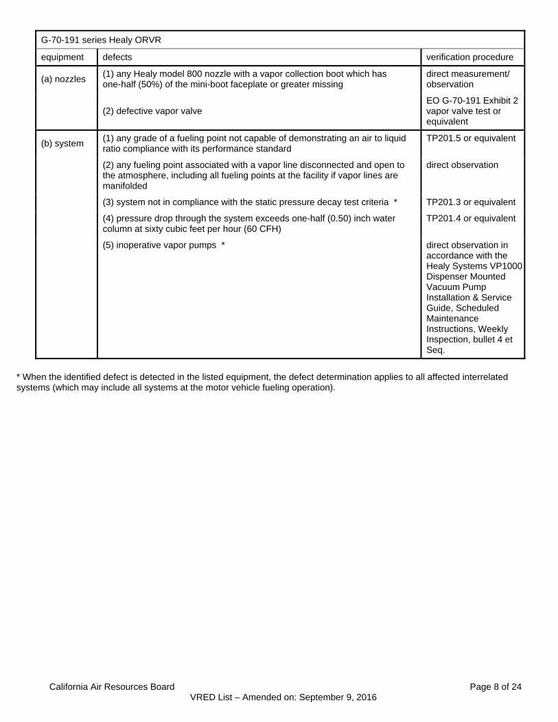
G-70-191 series Healy ORVR
equipment defects verification procedure
(a) nozzles (1) any Healy model 800 nozzle with a vapor collection boot which has one-half (50%) of the mini-boot faceplate or greater missing
direct measurement/ observation
(2) defective vapor valve EO G-70-191 Exhibit 2 vapor valve test or equivalent
(b) system (1) any grade of a fueling point not capable of demonstrating an air to liquid ratio compliance with its performance standard
TP201.5 or equivalent
(2) any fueling point associated with a vapor line disconnected and open to the atmosphere, including all fueling points at the facility if vapor lines are manifolded
direct observation
(3) system not in compliance with the static pressure decay test criteria * TP201.3 or equivalent
(4) pressure drop through the system exceeds one-half (0.50) inch water column at sixty cubic feet per hour (60 CFH)
TP201.4 or equivalent
(5) inoperative vapor pumps * direct observation in accordance with the Healy Systems VP1000 Dispenser Mounted Vacuum Pump Installation & Service Guide, Scheduled Maintenance Instructions, Weekly Inspection, bullet 4 et Seq.
* When the identified defect is detected in the listed equipment, the defect determination applies to all affected interrelated systems (which may include all systems at the motor vehicle fueling operation).
California Air Resources Board Page 9 of 24 VRED List – Amended on: September 9, 2016
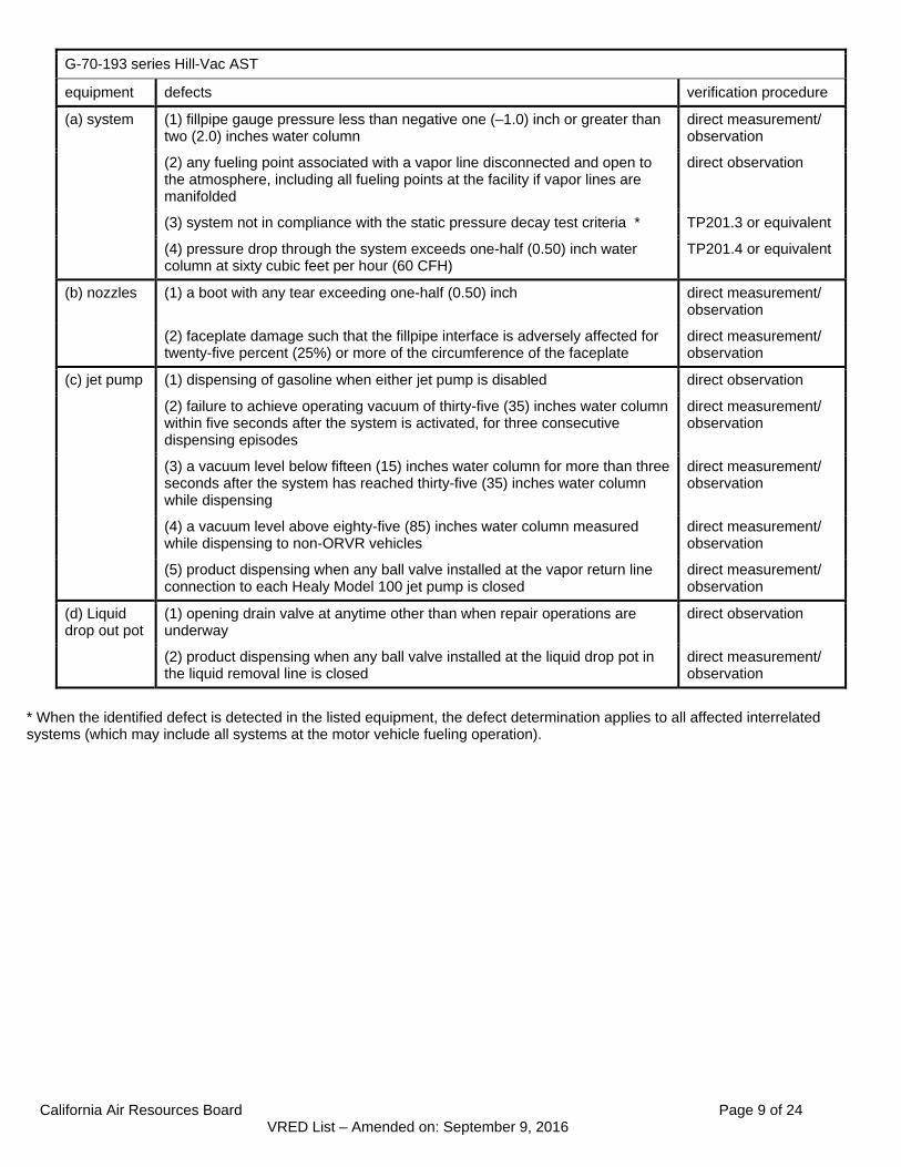
G-70-193 series Hill-Vac AST
equipment defects verification procedure
(a) system (1) fillpipe gauge pressure less than negative one (–1.0) inch or greater than two (2.0) inches water column
direct measurement/ observation
(2) any fueling point associated with a vapor line disconnected and open to the atmosphere, including all fueling points at the facility if vapor lines are manifolded
direct observation
(3) system not in compliance with the static pressure decay test criteria * TP201.3 or equivalent
(4) pressure drop through the system exceeds one-half (0.50) inch water column at sixty cubic feet per hour (60 CFH)
TP201.4 or equivalent
(b) nozzles (1) a boot with any tear exceeding one-half (0.50) inch direct measurement/ observation
(2) faceplate damage such that the fillpipe interface is adversely affected for twenty-five percent (25%) or more of the circumference of the faceplate
direct measurement/ observation
(c) jet pump (1) dispensing of gasoline when either jet pump is disabled direct observation
(2) failure to achieve operating vacuum of thirty-five (35) inches water column within five seconds after the system is activated, for three consecutive dispensing episodes
direct measurement/ observation
(3) a vacuum level below fifteen (15) inches water column for more than three seconds after the system has reached thirty-five (35) inches water column while dispensing
direct measurement/ observation
(4) a vacuum level above eighty-five (85) inches water column measured while dispensing to non-ORVR vehicles
direct measurement/ observation
(5) product dispensing when any ball valve installed at the vapor return line connection to each Healy Model 100 jet pump is closed
direct measurement/ observation
(d) Liquid drop out pot
(1) opening drain valve at anytime other than when repair operations are underway
direct observation
(2) product dispensing when any ball valve installed at the liquid drop pot in the liquid removal line is closed
direct measurement/ observation
* When the identified defect is detected in the listed equipment, the defect determination applies to all affected interrelated systems (which may include all systems at the motor vehicle fueling operation).

California Air Resources Board Page 10 of 24 VRED List – Amended on: September 9, 2016
G-70-200 series Oldcastle Buried Vapor Return Piping AST G-70-201 series Oldcastle Trenched Vapor Return Piping AST
equipment defects verification procedure
(a) nozzles (1) any nozzle boot torn in one or more of the following manners: a triangular-shaped or similar tear one-half (0.50) inch or more on any side, or hole one-half (0.50) inch or more in diameter, or slit one (1.0) inch or more in length
direct measurement/ observation
(2) any faceplate or flexible cone damaged in the following manner: for balance nozzles and for nozzles for aspirator and eductor assist type systems, damage such that the capability to achieve a seal with a fill pipe interface is affected for one-fourth (25%) of the circumference of the faceplate (accumulated)
direct measurement/ observation
(3) flexible cone damaged in the following manner: for booted type nozzles for vacuum assist-type systems, more than one-fourth (25%) of the flexible cone missing
direct measurement/ observation
(4) insertion interlock mechanism which will allow dispensing when the bellow is uncompressed
direct observation/ GDF-09
(b) hoses (1) any coaxial balance hose with 100 ml or more liquid in the vapor path direct measurement
(2) any hose with a visible opening direct observation
(c) processing unit
(1) vapor processing unit inoperative * direct observation
* When the identified defect is detected in the listed equipment, the defect determination applies to all affected interrelated systems (which may include all systems at the motor vehicle fueling operation).

California Air Resources Board Page 11 of 24 VRED List – Amended on: September 9, 2016
G-70-202 series Gilbarco Vapor Vac AST
equipment defects verification procedure
(a) system (1) any fueling point associated with a vapor line disconnected and open to the atmosphere, including all fueling points at the facility if vapor lines are manifolded
direct observation
(2) both booted and unbooted nozzle types connected to the same vapor pump
direct observation
(3) any grade of a fueling point not capable of demonstrating an air to liquid ratio compliance with its performance standard
TP201.5 or equivalent
(b) Catlow ICVN nozzle
(1) less than three unblocked vapor holes direct observation
(2) defective vapor valve GDF-01/GDF-02
(3) efficiency compliance device slit from base to the rim direct observation
(c) Emco Wheaton A4505 nozzle
(1) less than three unblocked vapor holes direct observation
(2) defective vapor valve GDF-01/GDF-02
(3) one-eighth (13%) of vapor guard circumference missing direct measurement/ observation
(d) Emco Wheaton A4500 nozzle
(1) less than three unblocked vapor holes direct observation
(e) Husky V34 6250 nozzle
(1) a one and one-half (1.5) inch or greater slit in vapor splash guard direct measurement/ observation
(2) any hole greater than three-eighths (0.38) inch in vapor splash guard direct measurement/ observation
(3) defective vapor valve GDF-01/GDF-02
(f) Husky V3 6201 nozzle
(1) all vapor holes blocked direct observation
(g) OPW 11VAI nozzle
(1) less than four unblocked vapor holes direct observation
(h) OPW12VW nozzle
(1) all vapor holes blocked direct observation
(2) defective vapor valve GDF-01/GDF-02
(3) vapor escape guard with three-fourths (75%) of the circumference missing
direct measurement/ observation

California Air Resources Board Page 12 of 24 VRED List – Amended on: September 9, 2016
G-70-204 series Gilbarco Vapor Vac/OPW Vaporsaver
equipment Defects verification procedure
(a) system (1) pressure drop through the system exceeds one-half (0.50) inch water column at sixty cubic feet per hour (60 CFH) *
TP201.4 or equivalent
(2) any fueling point associated with a vapor line disconnected and open to the atmosphere, including all fueling points at the facility if vapor lines are manifolded
direct observation
(3) system not in compliance with the static pressure decay test criteria * TP201.3 or equivalent
(4) any grade of a fueling point not capable of demonstrating an air to liquid ratio compliance with its performance standard
TP201.5 or equivalent
(5) defective vapor valve GDF-01/GDF-02
(b) Catlow ICVN nozzle
(1) less than three unblocked vapor holes direct observation
(2) efficiency compliance device slit from base to the rim direct observation
(c) Emco Wheaton A4505 nozzle
(1) less than three unblocked vapor holes direct observation
(2) one-eighth (1/8) of vapor guard circumference missing or equivalent cumulative damage
direct measurement/ observation
(d) Husky V34 6250 nozzle
(1) a one and one-half (1.5) inch or greater slit in vapor splash guard or equivalent cumulative damage
direct measurement/ observation
(2) any hole greater than three-eighths (3/8) inch in vapor splash guard or equivalent cumulative damage
direct measurement/ observation
(e) OPW12VW nozzle
(1) all vapor holes blocked direct observation
(2) vapor escape guard with three-fourths (3/4) of the circumference missing or equivalent cumulative damage
direct measurement/ observation
(f) vapor processor
(1) vapor processor inoperative for more than 24 consecutive hours * direct observation/ G-70-204 Exhibit 2
* When the identified defect is detected in the listed equipment, the defect determination applies to all affected interrelated systems (which may include all systems at the motor vehicle fueling operation).
California Air Resources Board Page 13 of 24 VRED List – Amended on: September 9, 2016
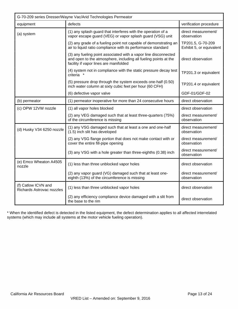
G-70-209 series Dresser/Wayne Vac/Arid Technologies Permeator
equipment defects verification procedure
(a) system (1) any splash guard that interferes with the operation of a vapor escape guard (VEG) or vapor splash guard (VSG) unit
direct measurement/ observation
(2) any grade of a fueling point not capable of demonstrating an air to liquid ratio compliance with its performance standard
TP201.5, G-70-209 Exhibit 5, or equivalent
(3) any fueling point associated with a vapor line disconnected and open to the atmosphere, including all fueling points at the facility if vapor lines are manifolded
direct observation
(4) system not in compliance with the static pressure decay test criteria *
TP201.3 or equivalent
(5) pressure drop through the system exceeds one-half (0.50) inch water column at sixty cubic feet per hour (60 CFH)
TP201.4 or equivalent
(6) defective vapor valve GDF-01/GDF-02
(b) permeator (1) permeator inoperative for more than 24 consecutive hours direct observation
(c) OPW 12VW nozzle (1) all vapor holes blocked direct observation
(2) any VEG damaged such that at least three-quarters (75%) of the circumference is missing
direct measurement/ observation
(d) Husky V34 6250 nozzle (1) any VSG damaged such that at least a one and one-half (1.5) inch slit has developed
direct measurement/ observation
(2) any VSG flange portion that does not make contact with or cover the entire fill-pipe opening
direct measurement/ observation
(3) any VSG with a hole greater than three-eighths (0.38) inch direct measurement/ observation
(e) Emco Wheaton A4505 nozzle
(1) less than three unblocked vapor holes direct observation
(2) any vapor guard (VG) damaged such that at least one-eighth (13%) of the circumference is missing
direct measurement/ observation
(f) Catlow ICVN and Richards Astrovac nozzles
(1) less than three unblocked vapor holes direct observation
(2) any efficiency compliance device damaged with a slit from the base to the rim
direct observation
* When the identified defect is detected in the listed equipment, the defect determination applies to all affected interrelated systems (which may include all systems at the motor vehicle fueling operation).
California Air Resources Board Page 14 of 24 VRED List – Amended on: September 9, 2016
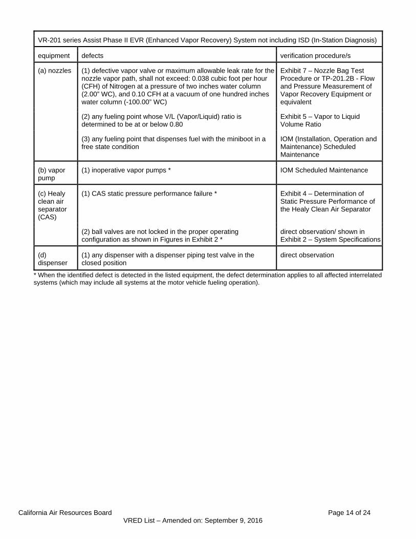
VR-201 series Assist Phase II EVR (Enhanced Vapor Recovery) System not including ISD (In-Station Diagnosis)
equipment defects verification procedure/s
(a) nozzles (1) defective vapor valve or maximum allowable leak rate for the nozzle vapor path, shall not exceed: 0.038 cubic foot per hour (CFH) of Nitrogen at a pressure of two inches water column (2.00” WC), and 0.10 CFH at a vacuum of one hundred inches water column (-100.00” WC)
Exhibit 7 – Nozzle Bag Test Procedure or TP-201.2B - Flow and Pressure Measurement of Vapor Recovery Equipment or equivalent
(2) any fueling point whose V/L (Vapor/Liquid) ratio is determined to be at or below 0.80
Exhibit 5 – Vapor to Liquid Volume Ratio
(3) any fueling point that dispenses fuel with the miniboot in a free state condition
IOM (Installation, Operation and Maintenance) Scheduled Maintenance
(b) vapor pump
(1) inoperative vapor pumps * IOM Scheduled Maintenance
(c) Healy clean air separator (CAS)
(1) CAS static pressure performance failure * Exhibit 4 – Determination of Static Pressure Performance of the Healy Clean Air Separator
(2) ball valves are not locked in the proper operating configuration as shown in Figures in Exhibit 2 *
direct observation/ shown in Exhibit 2 – System Specifications
(d) dispenser
(1) any dispenser with a dispenser piping test valve in the closed position
direct observation
* When the identified defect is detected in the listed equipment, the defect determination applies to all affected interrelated systems (which may include all systems at the motor vehicle fueling operation).

California Air Resources Board Page 15 of 24 VRED List – Amended on: September 9, 2016
VR-202 series Assist Phase II EVR System Including ISD
equipment defects verification procedure/s
(a) nozzles (1) defective vapor valve - maximum allowable leak rate for the nozzle vapor path, shall not exceed: 0.038 cubic foot per hour (CFH) of Nitrogen at a pressure of two inches water column (2.00” WC), and 0.10 CFH at a vacuum of one hundred inches water column (-100.00” WC)
TP-201.2B - Flow and Pressure Measurement of Vapor Recovery Equipment or equivalent, or Exhibit 7 – Nozzle Bag Test Procedure
(2) any fueling point whose V/L ratio is determined to be at or below 0.80
Exhibit 5 – Vapor to Liquid Volume Ratio or an ARB approved alternate procedure
(3) any fueling point that dispenses fuel with the miniboot in a free state condition
IOM Scheduled Maintenance
(b) vapor pump
(1) inoperative vapor pumps * IOM Scheduled Maintenance
(c) Healy clean air separator (CAS)
(1) CAS static pressure performance failure* Exhibit 4 – Determination of Static Pressure Performance of the Healy Clean Air Separator
(2) ball valves are not locked in the proper operating configuration as shown in Figures in Exhibit 2 *
direct observation/ shown in Exhibit 2 – System Specifications
(d) dispenser (1) any dispenser with a dispenser piping test valve in the closed position
direct observation
* When the identified defect is detected in the listed equipment, the defect determination applies to all affected interrelated systems (which may include all systems at the motor vehicle fueling operation).

California Air Resources Board Page 16 of 24 VRED List – Amended on: September 9, 2016
VR-203 series Balance Phase II EVR System not including ISD
equipment defects verification procedure/s
(a) VST nozzle
(1) more than 30 percent (30%) of a nozzle face seal is missing (e.g., a triangular or similar shape in which greater than two and one half (2.5) inches of the face seal circumference is missing (accumulated))
direct measurement/ observation
(2) more than 0.4 square inches of a nozzle vapor collection sleeve is missing (e.g., a rectangular shape of greater than nine sixteenths (9/16) inch or more on each side, a circular shape of eleven sixteenths (11/16) inch or more in diameter, or a triangular shape of seven eighths (7/8) inch on the side
direct measurement/ observation
(3) cumulative slit length in the convolution/s exceeds 18.0 inches
direct measurement/ observation
(b) EMCO nozzle
(1) more than 0.4 square inches of a nozzle boot face material is missing (e.g., a triangular or similar shape in which greater than 7/16 inches of the boot face circumference is missing (accumulated))
direct measurement/ observation
(2) slit across seven (7) consecutive bellows convolutions direct measurement/ observation
(3) a 360 degree cut around the bellows convolutions direct measurement/ observation
(c) all nozzles (1) defective vapor valve or Exhibit 7 – Nozzle Bag Test Procedure or
vapor valve leak rate exceeds 0.07 cubic feet per hour of Nitrogen at a pressure of two inches water column (2.00” WC)
TP-201.2B - Flow and Pressure Measurement of Vapor Recovery Equipment
(2) nozzle lever has spring tension (live lever) when the vapor recovery sleeve or bellows/convolutions is uncompressed
IOM Weekly Inspections
(d) hoses (1) 150 ml or more liquid in the vapor path direct measurement/ Sections 6.1 to 6.5 of Exhibit 5 - Liquid Removal Test Procedure
(2) any hose with a visible opening direct observation
(e) vapor return lines
(1) pressure drop through the vapor path exceeds ninety-five hundredths (0.95) inches water column at a flow rate 60 cubic foot per hour (CFH) of Nitrogen and one and fifty-two hundredths (1.52) inches water column at a flow rate of 80 CFH of Nitrogen.
Methodology 1 of TP-201.4 – Dynamic Back Pressure and Exhibit 6 - Required Items for Conducting TP-201.4
* When the identified defect is detected in the listed equipment, the defect determination applies to all affected interrelated systems (which may include all systems at the motor vehicle fueling operation).

California Air Resources Board Page 17 of 24 VRED List – Amended on: September 9, 2016
VR-203 series Balance Phase II EVR System sans not including ISD
equipment defect verification procedure/s
(f) VST ECS processor
(1) ball valves are not locked in the proper operating configuration as shown in Figures in Exhibit 2 * (except when maintenance or testing is being conducted.)
direct observation/ shown in Exhibit 2– System Specifications
(2) unit is not on or is not in the automatic vapor processor mode* (except when maintenance or testing is being conducted.)
diagnostic section
(g) Veeder-Root vapor polisher
(1) ball valve is not locked in the proper operating configuration as shown in Figure in Exhibit 2 (except when maintenance or testing is being conducted.) *
direct observation/ shown in Figures in Exhibit 2 – System Specifications
(2) unit is not on or is not in the automatic vapor processor mode (except when maintenance or testing is being conducted.) *
PMC Diagnostic report per ‘PMC Diagnostic Menus’ section of IOM
(h) Hirt thermal oxidizer
(1) ball valve is not locked in the proper operating configuration *
direct observation/ shown in Figures in Exhibit 2 – System Specifications
(2) thermal oxidizer indicator panel is not in the “power on” position (power lamp is lit) (except when maintenance or testing is being conducted.) *
direct observation/ shown in Figure in Exhibit 1 – Equipment List
(i) Healy clean air separator (CAS)
(1) ball valves are not locked in the proper operating configuration * (except when maintenance or testing is being conducted.)
direct observation/ shown in figures in Exhibit 2 – System Specifications
(2) clean air separator static pressure performance failure * Exhibit 14 -Determination of Static Pressure Performance of the Healy Clean Air Separator
(j) VST Green Machine processor
(1) ball valves are not locked in the proper operating configuration (except when maintenance or testing is being conducted.) *
direct observation / Figure shown in Exhibit 2 – System Specifications
(2) processor is not on or is not in the automatic vapor processor mode (except when maintenance or testing is being conducted.) *
diagnostic Section of IOM
(3) controller is not on (except when maintenance or testing is being conducted.) *
VST Control Panel Section of IOM
* When the identified defect is detected in the listed equipment, the defect determination applies to all affected interrelated systems (which may include all systems at the motor vehicle fueling operation).

California Air Resources Board Page 18 of 24 VRED List – Amended on: September 9, 2016
VR-204 series Balance Phase II EVR System Including ISD
equipment defect verification procedure/s
(a) VST nozzle (1) more than 30 percent (30%) of a nozzle face seal is missing (e.g., a triangular or similar shape in which greater than two and one half (2.5) inches of the face seal circumference is missing (accumulated))
direct measurement/ observation
(2) more than 0.4 square inches of a nozzle vapor collection sleeve is missing (e.g., a rectangular shape of greater than nine sixteenths (9/16) inch or more on each side, a circular shape of eleven sixteenths (11/16) inch or more in diameter, or a triangular shape of seven eighths (7/8) inch on the side
direct measurement/ observation
(3) cumulative slit length in the convolution/s exceeds 18.0 inches
direct measurement/ observation
(b) EMCO nozzle
(1) more than 0.4 square inches of a nozzle boot face material is missing (e.g., a triangular or similar shape in which greater than 7/16 inches of the boot face circumference is missing (accumulated))
direct measurement/ observation
(2) slit across seven (7) consecutive bellows convolutions direct measurement/ observation
(3) there is a 360 degree cut around the bellows convolutions direct measurement/ observation
(c) all nozzles (1) defective vapor valve or Exhibit 7 – Nozzle Bag Test Procedure or
vapor valve leak rate exceeds 0.07 cubic feet per hour of Nitrogen at a pressure of two inches water column (2.00“ WC)
TP-201.2B - Flow and Pressure Measurement of Vapor Recovery Equipment
(2) nozzle lever has spring tension (live lever) when the vapor recovery sleeve or bellows/convolutions is uncompressed
IOM Weekly Inspection
(d) hoses (1) 150 ml or more liquid in the vapor path direct measurement/ Sections 6.1 to 6.5 of Exhibit 5 - Liquid Removal Test Procedure
(2) any hose with a visible opening direct observation
(e) vapor return lines
(1) pressure drop through the vapor path exceeds ninety-five hundredths (0.95) inches water column at a flow rate 60 cubic foot per hour (CFH) of Nitrogen and one and fifty-two hundredths (1.52) inches water column at a flow rate of 80 CFH of Nitrogen.
Methodology 1 of TP-201.4 – Dynamic Back Pressure and Exhibit 6 - Required Items for Conducting TP-201.4
(f) VST ECS processor
(1) ball valves are not in the proper operating configuration as shown in Figures in Exhibit 2 *
direct observation/ shown in Exhibit 2 – System Specifications
(2) unit is not on or is not in the automatic vapor processor mode *
diagnostic section of IOM
(g) Veeder-Root vapor polisher
(1) ball valves are not in the proper operating configuration as shown in Figures in Exhibit 2 (except when maintenance or testing is being conducted.) *
direct observation / shown in Figures in Exhibit 2 – System Specifications
(2) unit is not on or is not in the automatic vapor processor mode (except when maintenance or testing is being conducted.) *
diagnostic section of IOM
* When the identified defect is detected in the listed equipment, the defect determination applies to all affected interrelated systems (which may include all systems at the motor vehicle fueling operation).

California Air Resources Board Page 19 of 24 VRED List – Amended on: September 9, 2016
VR-204 series Balance Phase II EVR System Including ISD
equipment defect verification procedure/s
(h) Hirt thermal oxidizer
(1) ball valve is not locked in the proper operating configuration (except when maintenance or testing is being conducted.) *
direct observation/ shown in Exhibit 2 – System Specifications
(2) thermal oxidizer indicator panel is not in the “power on” position (power lamp is lit)*(except when maintenance or testing is being conducted.)
direct observation / shown in Figure in Exhibit 1 – Equipment List
(i) Healy clean air separator (CAS)
(1) ball valves are not locked in the proper operating configuration * (except when maintenance or testing is being conducted.)
direct observation/ shown in figures in Exhibit 2 – System Specifications
(2) clean air separator static pressure performance failure * Exhibit 14 - Determination of Static Pressure Performance of the Healy Clean Air Separator
(j) VST Green Machine processor
(1) ball valves are not locked in the proper operating configuration (except when maintenance or testing is being conducted.) *
direct observation / shown in Figure in Exhibit 2 – System Specifications
(2) unit is not on or is not in the automatic vapor processor mode (except when maintenance or testing is being conducted.) *
diagnostic section of IOM
(3) controller is not on (except when maintenance or testing is being conducted.) *
VST Control Panel section of IOM
* When the identified defect is detected in the listed equipment, the defect determination applies to all affected interrelated systems (which may include all systems at the motor vehicle fueling operation).
California Air Resources Board Page 20 of 24 VRED List – Amended on: September 9, 2016
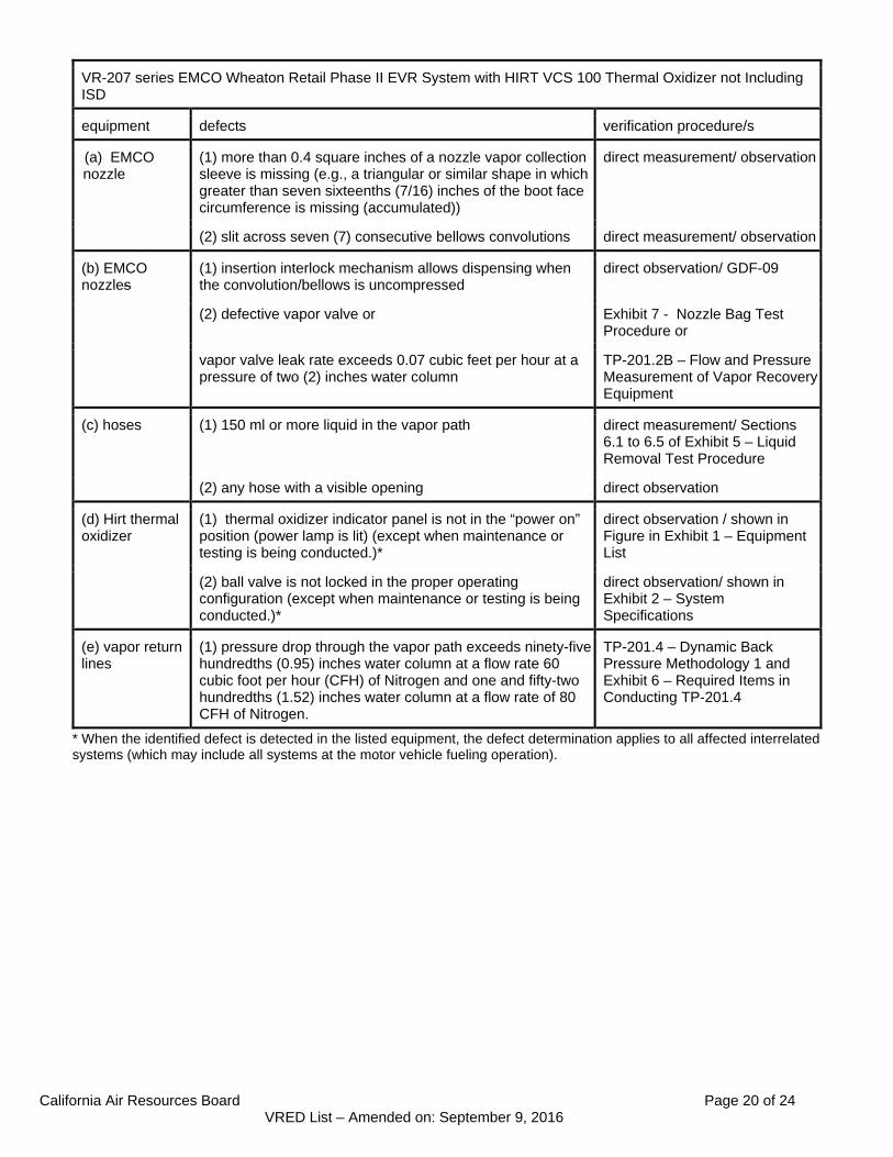
VR-207 series EMCO Wheaton Retail Phase II EVR System with HIRT VCS 100 Thermal Oxidizer not Including ISD
equipment defects verification procedure/s
(a) EMCO nozzle
(1) more than 0.4 square inches of a nozzle vapor collection sleeve is missing (e.g., a triangular or similar shape in which greater than seven sixteenths (7/16) inches of the boot face circumference is missing (accumulated))
direct measurement/ observation
(2) slit across seven (7) consecutive bellows convolutions direct measurement/ observation
(b) EMCO nozzles
(1) insertion interlock mechanism allows dispensing when the convolution/bellows is uncompressed
direct observation/ GDF-09
(2) defective vapor valve or Exhibit 7 - Nozzle Bag Test Procedure or
vapor valve leak rate exceeds 0.07 cubic feet per hour at a pressure of two (2) inches water column
TP-201.2B – Flow and Pressure Measurement of Vapor Recovery Equipment
(c) hoses (1) 150 ml or more liquid in the vapor path direct measurement/ Sections 6.1 to 6.5 of Exhibit 5 – Liquid Removal Test Procedure
(2) any hose with a visible opening direct observation
(d) Hirt thermal oxidizer
(1) thermal oxidizer indicator panel is not in the “power on” position (power lamp is lit) (except when maintenance or testing is being conducted.)*
direct observation / shown in Figure in Exhibit 1 – Equipment List
(2) ball valve is not locked in the proper operating configuration (except when maintenance or testing is being conducted.)*
direct observation/ shown in Exhibit 2 – System Specifications
(e) vapor return lines
(1) pressure drop through the vapor path exceeds ninety-five hundredths (0.95) inches water column at a flow rate 60 cubic foot per hour (CFH) of Nitrogen and one and fifty-two hundredths (1.52) inches water column at a flow rate of 80 CFH of Nitrogen.
TP-201.4 – Dynamic Back Pressure Methodology 1 and Exhibit 6 – Required Items in Conducting TP-201.4
* When the identified defect is detected in the listed equipment, the defect determination applies to all affected interrelated systems (which may include all systems at the motor vehicle fueling operation).

California Air Resources Board Page 21 of 24 VRED List – Amended on: September 9, 2016
VR-208 series EMCO Wheaton Retail Phase II EVR System with HIRT VCS 100 Thermal Oxidizer Including ISD
equipment defects verification procedure/s
(a) EMCO nozzle (1) more than 0.4 square inches of a nozzle boot face material is missing (e.g., a triangular or similar shape in which greater than 7/16 inches of the boot face circumference is missing (accumulated))
direct measurement/ observation
(2) slit across seven (7) consecutive bellows convolutions direct measurement/ observation
(b) all nozzles (1) insertion interlock mechanism which will allow dispensing when the bellows is uncompressed
direct observation/ GDF-09
(2) defective vapor valve or Exhibit 7 – Nozzle Bag Test Procedure or
vapor valve leak rate exceeds 0.07 cubic feet per hour at a pressure of two (2) inches water column
TP-201.2B - Flow and Pressure Measurement of Vapor Recovery Equipment
(c) hoses (1) 150 ml or more liquid in the vapor path direct measurement/ Sections 6.1 to 6.5 of Exhibit 5 - Liquid Removal Test Procedure
(2) any hose with a visible opening direct observation
(d) Hirt thermal oxidizer
(1) ball valve is not locked in the proper operating configuration (except when maintenance or testing is being conducted.)
direct observation/ shown in Exhibit 2 – System Specifications
(2) thermal oxidizer indicator panel “power on” lamp off (except when maintenance or testing is being conducted.)*
direct observation
(e) vapor return lines
(1) pressure drop through the vapor path exceeds ninety-five hundredths (0.95) inches water column at a flow rate 60 cubic foot per hour (CFH) of Nitrogen and one and fifty-two hundredths (1.52) inches water column inches at a flow rate of 80 CFH of Nitrogen.
Methodology 1 of TP-201.4 – Dynamic Back Pressure and Exhibit 6 – Required Items in Conducting TP-201.4
* When the identified defect is detected in the listed equipment, the defect determination applies to all affected interrelated systems (which may include all systems at the motor vehicle fueling operation).

California Air Resources Board Page 22 of 24 VRED List – Amended on: September 9, 2016
VR-501 series Balance Phase II EVR System for Protected AST with Remote Dispensing
equipment defects verification procedure/s
(a) EMCO nozzle
(1) more than 0.4 square inches of a nozzle vapor collection sleeve is missing (e.g., a triangular or similar shape in which greater than seven sixteenths (7/16) inches of the boot face circumference is missing (accumulated))
direct measurement/ observation
(2) slit across seven (7) consecutive bellows convolutions direct measurement/ observation
(3) a 360 degree cut around the bellows convolutions direct measurement/ observation
(b) all nozzles (1) defective vapor valve or vapor valve leak rate exceeds 0.07 cubic feet per hour at a pressure of two (2) inches water column
Exhibit 7 - Nozzle Bag Test Procedure or TP-201.2B – Flow and Pressure Measurement of Vapor Recovery Equipment
(2) nozzle lever has spring tension (live lever) when the vapor recovery sleeve or bellows/convolutions is uncompressed
IOM Weekly Inspections
(c) hoses (1) 150 ml or more liquid in the vapor path direct measurement/ Sections 6.1 to 6.5 of Exhibit 5 – Liquid Removal Test Procedure
(2) any hose with a visible opening direct observation
(d) Hirt thermal oxidizer
(1) thermal oxidizer indicator panel is not in the “power on” position (power lamp is lit) *(except when maintenance or testing is being conducted.)
direct observation
(2) ball valve is not locked in the proper operating configuration (except when maintenance or testing is being conducted.) *
direct observation
(e) vapor return lines
(1) pressure drop through the vapor path exceeds ninety-five hundredths (0.95) inches water column at a flow rate 60 cubic foot per hour (CFH) of Nitrogen and one and fifty-two hundredths (1.52) inches water column at a flow rate of 80 CFH of Nitrogen.
TP-201.4 – Dynamic Back Pressure Methodology 1 and Exhibit 6 – Required Items in Conducting TP-201.4
* When the identified defect is detected in the listed equipment, the defect determination applies to all affected interrelated systems (which may include all systems at the motor vehicle fueling operation).
California Air Resources Board Page 23 of 24 VRED List – Amended on: September 9, 2016
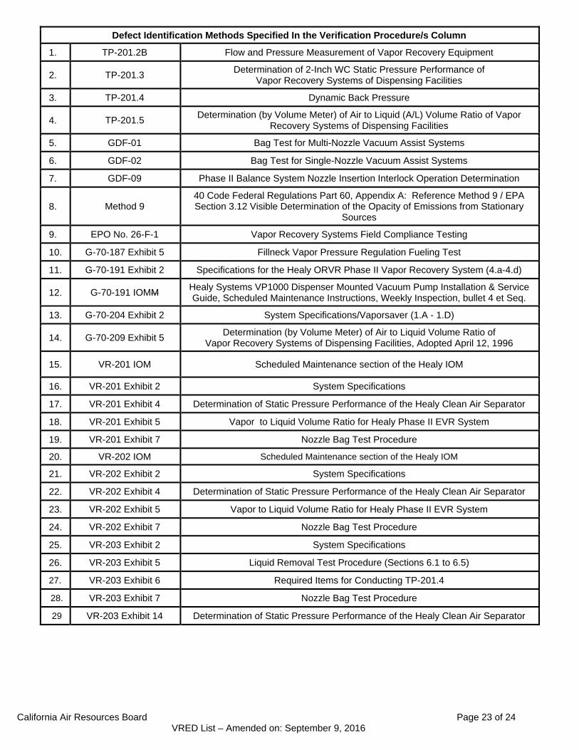
Defect Identification Methods Specified In the Verification Procedure/s Column
1. TP-201.2B Flow and Pressure Measurement of Vapor Recovery Equipment
2. TP-201.3 Determination of 2-Inch WC Static Pressure Performance of
Vapor Recovery Systems of Dispensing Facilities
3. TP-201.4 Dynamic Back Pressure
4. TP-201.5 Determination (by Volume Meter) of Air to Liquid (A/L) Volume Ratio of Vapor
Recovery Systems of Dispensing Facilities
5. GDF-01 Bag Test for Multi-Nozzle Vacuum Assist Systems
6. GDF-02 Bag Test for Single-Nozzle Vacuum Assist Systems
7. GDF-09 Phase II Balance System Nozzle Insertion Interlock Operation Determination
8. Method 9 40 Code Federal Regulations Part 60, Appendix A: Reference Method 9 / EPA Section 3.12 Visible Determination of the Opacity of Emissions from Stationary
Sources
9. EPO No. 26-F-1 Vapor Recovery Systems Field Compliance Testing
10. G-70-187 Exhibit 5 Fillneck Vapor Pressure Regulation Fueling Test
11. G-70-191 Exhibit 2 Specifications for the Healy ORVR Phase II Vapor Recovery System (4.a-4.d)
12. G-70-191 IOMM Healy Systems VP1000 Dispenser Mounted Vacuum Pump Installation & Service Guide, Scheduled Maintenance Instructions, Weekly Inspection, bullet 4 et Seq.
13. G-70-204 Exhibit 2 System Specifications/Vaporsaver (1.A - 1.D)
14. G-70-209 Exhibit 5 Determination (by Volume Meter) of Air to Liquid Volume Ratio of
Vapor Recovery Systems of Dispensing Facilities, Adopted April 12, 1996
15. VR-201 IOM Scheduled Maintenance section of the Healy IOM
16. VR-201 Exhibit 2 System Specifications
17. VR-201 Exhibit 4 Determination of Static Pressure Performance of the Healy Clean Air Separator
18. VR-201 Exhibit 5 Vapor to Liquid Volume Ratio for Healy Phase II EVR System
19. VR-201 Exhibit 7 Nozzle Bag Test Procedure
20. VR-202 IOM Scheduled Maintenance section of the Healy IOM
21. VR-202 Exhibit 2 System Specifications
22. VR-202 Exhibit 4 Determination of Static Pressure Performance of the Healy Clean Air Separator
23. VR-202 Exhibit 5 Vapor to Liquid Volume Ratio for Healy Phase II EVR System
24. VR-202 Exhibit 7 Nozzle Bag Test Procedure
25. VR-203 Exhibit 2 System Specifications
26. VR-203 Exhibit 5 Liquid Removal Test Procedure (Sections 6.1 to 6.5)
27. VR-203 Exhibit 6 Required Items for Conducting TP-201.4
28. VR-203 Exhibit 7 Nozzle Bag Test Procedure
29 VR-203 Exhibit 14 Determination of Static Pressure Performance of the Healy Clean Air Separator
California Air Resources Board Page 24 of 24 VRED List – Amended on: September 9, 2016
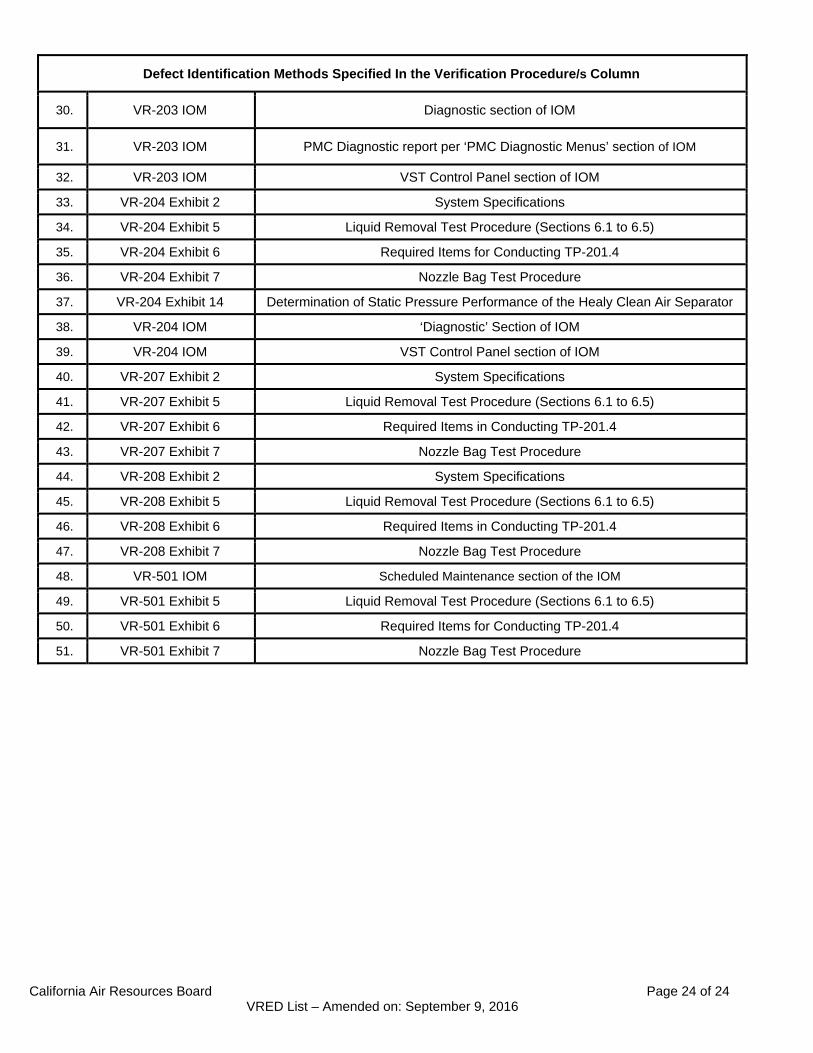
Defect Identification Methods Specified In the Verification Procedure/s Column
30. VR-203 IOM Diagnostic section of IOM
31. VR-203 IOM PMC Diagnostic report per ‘PMC Diagnostic Menus’ section of IOM
32. VR-203 IOM VST Control Panel section of IOM
33. VR-204 Exhibit 2 System Specifications
34. VR-204 Exhibit 5 Liquid Removal Test Procedure (Sections 6.1 to 6.5)
35. VR-204 Exhibit 6 Required Items for Conducting TP-201.4
36. VR-204 Exhibit 7 Nozzle Bag Test Procedure
37. VR-204 Exhibit 14 Determination of Static Pressure Performance of the Healy Clean Air Separator
38. VR-204 IOM ‘Diagnostic’ Section of IOM
39. VR-204 IOM VST Control Panel section of IOM
40. VR-207 Exhibit 2 System Specifications
41. VR-207 Exhibit 5 Liquid Removal Test Procedure (Sections 6.1 to 6.5)
42. VR-207 Exhibit 6 Required Items in Conducting TP-201.4
43. VR-207 Exhibit 7 Nozzle Bag Test Procedure
44. VR-208 Exhibit 2 System Specifications
45. VR-208 Exhibit 5 Liquid Removal Test Procedure (Sections 6.1 to 6.5)
46. VR-208 Exhibit 6 Required Items in Conducting TP-201.4
47. VR-208 Exhibit 7 Nozzle Bag Test Procedure
48. VR-501 IOM Scheduled Maintenance section of the IOM
49. VR-501 Exhibit 5 Liquid Removal Test Procedure (Sections 6.1 to 6.5)
50. VR-501 Exhibit 6 Required Items for Conducting TP-201.4
51. VR-501 Exhibit 7 Nozzle Bag Test Procedure
