valves digest€¦ · · 2017-03-17lines and from the body cavities turbine control valve when...
TRANSCRIPT
www.forbesmarshall.com
Forbes Marshall Pvt. Ltd.A-34/35, MIDC, Industrial Estate, ‘H’ Block, Pimpri, Pune - 411 018. India.Tel.: 91(0)20 - 27442020Fax: 91(0)20 - 27442040 E-mail: [email protected], [email protected]
Domestic:Ahmedabad, Alibag, Bangalore, Bhopal / Indore, Chandigarh, Chennai, Coimbatore, Delhi, Hyderabad, Jamshedpur, Kolkata, Mumbai, Nagpur, Navi Mumbai, Surat, Trichy, Vadodara, Visakhapatanam
International Operations: [email protected], Canada, Egypt, Indonesia, Iran, Kenya, Malaysia, Nepal, Sri Lanka, Thailand, U.A.E. (Instrumentation) (Boilers & Boiler Accessories), USA
Integrated Solutions for Process Efficiency
Valves Digest
Doc#
CIG
/091
2/32
1/V1
.R0

We Deliver Safety Safety – is synonymous with the valves that are manufactured by Forbes Marshall Group of Companies. Forbes Marshall valves are manufactured to the highest quality standard followed in the country today. An ISO9001 certified company, Forbes Marshall manufactures products that can be supplied to almost all industries. Be it in the field of Energy conservation or Instrumentation & Controls, Forbes Marshall has a product for most applications.
Valves for the Power Industry:
Forbes Marshall is in the field of Valves since the mid 1980's with a Joint Venture with some of the leading companies in Europe for manufacture of High Pressure Stop Valves, Safety Relief Valves, Turbine Drain, Continuous Blow down, Control Valves and Pressure Reducing and Desuperheating valves and Desuperheaters.
With Collaboration with M/s ARCA Regler Germany, Forbes Marshall is also able to offer valves for Steam and Feed Water Control for the Water and Steam Circuit of a Power Plant.
Efforts are on to enhance the existing range manufactured at the Pimpri Pune unit through indigenization of valves range with valves of the latest technology covering a wide range of sizes and pressure ratings that can be offered for most applications in power plants .
Designs to suit Indian Condition:
Investment in technically trained manpower has helped the company absorb the technology offered by collaborators at a fast pace and wherever appropriate, make changes/adjustments to make the same suitable for Indian Conditions without affecting the product performance.
Forbes Marshall Single stage and Multistage Drain Valves is one such product used for removing Condensate from the Reheater lines and from the body cavities Turbine Control Valve when there is a shutdown in a Power Plant for annual Maintenance or due to a Turbine Trip.
Turbine Drain valves handle high pressure condensate which is dropped across the valve seat. In spite of use of hard and erosion resistant material deposition like Stellite 6 at valve stem and seat.
2
Conventional type Globe valve starts passing at the seat after a few operations. Such failures at valve seat are due to cavitation and flashing which are common for such applications.
While it is difficult to eliminate cavitation completely when handling liquids at high pressure, the effects of cavitation on the valve can definitely be reduced by use of Valve the Multistage valve offered by Forbes Marshall. FM Multistage drain valve are designed specifically for handling high pressure drop across the valve seat before re-starting the turbine. When the plant is in operation, the drain valve offer a high level of leak tightness at valve seat. FM Drain valves have the added advantage of replaceable Trim making it economical for the customer as the customer needs to keep minimal spares for his annual maintenance. Replaceable valve internals provided the customer with the advantage of reduce maintenance down time and reduced cost of spare.
Forbes Marshall Safety Relief Valves and Relief Valves are already in operation at various Nuclear Installations in the country. FM has now also introduced Bellow seal Globe valves specifically to cater to the requirements of this industry. These valves are manufactured indigenously with minimal dependance on overseas vendors. Forbes Marshall is one of the few companies who have been able to take up the challenge of to qualify the valve design and manufacture the valves for such critical applications as demanded for in nuclear power plants.
Gate, Globe, Check and Ball valves are the latest addition to the wide range of valves that FM has to offer. With this FM can cater to the needs of Power, Oil & Gas, Petrochemical, Steel and several such industries.
Today Forbes Marshall is one of the few companies that has a product for each industry and for most processes. It has always been our endeavour to make products to suit Indian conditions without compromising on performance or quality.
3
Unique Features of High Pressure Globe Valves – Forbes Marshall MakeSome of the unique Features in a Forbes Marshall Globe Valves are discussed below:
It is often seen that Globe valve have to handle very high pressure across the valve seat. It is also known fact that in spite of having a stellite deposition at valve seat the seat is not able to withstand high pressure drops for a long time. While there is no foolproof and ready solution for this a valve manufacturer can only ensure that the life of the valve can be enhanced so that the replacement of valves are delayed if not totally eliminated.
One of the problems that has been identified as a possible reason for Valve failure at seat is Vibration of valve disc when the operator is closing the valve.
Cavitation and Flashing at the valve seat are one of the major reasons for valve passing at valve seat. However in addition to this one more prominent problem observed is vibration of valve disc, especially when the operator is closing the valve and disc is close to the valve seat.
Energy at inlet get converted into very high velocity at the lowest/smallest point of the restricted passage giving rise to flashing and high frequency vibration. In short the inlet pressure energy gets partly converted to Vibration Energy, Velocity, Noise etc.
A loose plug design for that brief moment gets affected badly and may vibrate at a very high frequency. The Seat is stellited which is hard but Brittle material and the high frequency vibration of plug at very close proximity to the seat can cause cracking of the seat and eventually valve passing. Forbes Marshall Valves have a single piece stem and disc arrangement which eliminate this problem.
Forbes Marshall Valves also have a line contact between the Disc
4
and Seat. Line contacts are able to seal better compared to Surface contact which are highly dependent on the matching of surface of plug and seat. With line contact between plug and disc the closing force by the valve operator is concentrated on the line of contact giving a better leak tightness.
Furthermore the possibility of any particulate matter getting stuck between the disc and seat at the line contact is much lower when compared to a surface to surface contact.
A non rotating spindle also helps to ensure that there multiple damage to the valve seat is avoided. In the event of cold weld between the Disc and any possible metallic foreign particle trapped between the disc and seat since the disc and spindle do not rotate, it is ensure that the same part of the disc is always in contact with same point on the seat, thus preventing multiple damage to the seat. Thereafter at the first available opportunity, the spindle can be replaced and the seat lapped/polished.
For applications wherein the valve is required to be kept in Crack or Semi Open position, we request that the same is indicated clearly to us. We treat such valve a bit differently.
Such valve may be used on Impulse Lines or on Gate valve Bypass Lines for Pressure Equalisation.
We offer a special accessory SN46 – Control Cone for such valve. With this accessory and in conjunction with the non rotating single piece Stem and Disc feature, we are able to separate the Seating area from the throttling area.
The valve is provided with a small extension to the disc and slots are made in the extension at a predetermined position below the seating section of the disc. As a result when the valve is opened, till the valve disc or plug is not moved sufficiently away from the seat, no real flow starts across the valve. Real flow starts only when the Slot section opens up to the valve inlet. As a result the effects of Cavitation and Flashing are kept away from the valve seat, saving the seating area of the valve.
5
Flow for such an application is reversed i.e. the conventionally Inlet Passage of the valve i.e. from Under the plug is made as the valve as the valve outlet. In short the valve is made to operate as a flow to close type.
The above method of handling very high pressure drop is a proven solution now in use oversea's by most European countries.
The valve Stem is Roller Burnished to Mirror Finish at the Gland Packing section. Roller burnishing is a unique procedure of improving the spindle surface finish to eliminate damage to the gland packing.
With Roller Burnishing ,the frictional forces are reduced considerable and gland packing tightness is assured free of leakage for a long time.
Seat Repair is possible without cutting the Body Bonnet weld joint. This is probably one of the very advantageous feature of this valve.
This is possible because of the following:
1) Roller Burnished Spindle i.e. spindle has a mirror finish which eliminates ware and tare of the Gland Packing during operation of the valve. The valve bonnet section housing the Gland Packing is also roller burnished to prevent damage to the Gland Packing when removing the same for maintenance.
Because of this, there is no need for a separate back seat arrangement.
To approach the valve seat one needs to bring the valve to its full open position, remove 4 nos. bolts on the cover flange located just below the Valve Hand wheel and unwind the Yoke bush from the Spindle threading.
Next unwind the bolts on the gland flange and release the Gland flange by lifting it upwards along with the protective ring placed just below the Gland Flange.
Now the valve is ready for disassembly of the full internals from the
6
top section of the valve.
Using the Yoke bush and Handwheel one can now one needs to screw the Yoke bush back on to the spindle and start rotating the handwheel.
The Left Hand Trapezoidal Yoke Bush Threads engage with the spindle threads lifting by pulling the spindle from the bonnet.
Thereafter once the Spindle is fully out of the bonnet one can free the Gland Flange from the oval shaped protective ring by tilting the Gland Flange in one direction and the ring in the reverse direction.
Using a Simple Z Bar which can be supported on the Yoke section one can use attach a Grinding plug to the Z Bar and put Emery Paper on it and carry out lapping/Polishing of the seat.
Depending on the number of valves used by the customer, such a Kit consisting of Hand Operated Z Bar, Emery Paper and Polishing Plug with a Rubber support can be supplied to the customer.
7

Drain/Blowdown Valve(InLine/Angle Pattern)
Size 3/8" - 2"10mm - 50mm
Rating #800 - #2500PN160 - PN 500
Material Carbon Steel (A 105)Alloy Steel (A182 F22)Stainless Steel (SS316)
End Connections Socket WeldButt WeldFlanged End
Application Feed WaterSteamChemicals
Certification IBR Form III-CExternal Agency (On Request)
Operation Electrical ActuatorPneumatic ActuatorManual operation with top mounted handwheel
Unique Features: • Single Piece, Non Rotating Spindle and Disc/Plug design. • Spindle roller burnished in gland packing section. • Specially designed slotted plug/multistage plug to handle high pressure drop across valve seat on CBD Service. • Hard Faced Parabolic Plug for IBD Service. • Lever Operated Design for IBD Service on request.
EKINx11
Globe Valve/Stop Valve(In Line/Angle Pattern)
Size 3/8" - 2" 10mm - 50mm
Rating #800 - #2500PN160 - PN 500
Material Carbon Steel (A 105)Alloy Steel (A182 F22)Stainless Steel (SS316)
End Connections Socket WeldButt WeldFlanged End
Application Feed WaterSteamChemicals
Certification IBR Form III-CExternal Agency (On Request)
Operation Electrical ActuatorPneumatic ActuatorManual operation with top mounted handwheel
Unique Features: • Single Piece, Non Rotating Spindle and Plug Design. • Spindle Roller Burnished in Gland Packing Section.
VKINx11
8

Drain/Blowdown Valve(Angle Pattern-Single Stage)
Size 3/8" - 3"10mm - 80mm
Rating #800 - #2500PN160 - PN 500
Material Carbon Steel (A 105)Alloy Steel (A182 F22)Stainless Steel (SS316)
End Connections Socket WeldButt WeldFlanged End
Application Feed WaterSteamChemicals
Certification IBR Form III-CExternal Agency (On Request)
Operation Electrical ActuatorPneumatic ActuatorHandwheel
Unique Features: • Single Piece, Non Rotating Spindle and Disc/Plug design. • Spindle roller burnished in gland packing section. • Specially designed parabolic plug to handle high pressure drop across valve seat on CBD Service. • Hard Faced Parabolic Plug for IBD Service. • Lever Operated Design for IBD Service on request. • Replaceable Seat Bush
ACTx5
10
Drain/Blowdown Valve(Angle Pattern-Multi Stage)
Size 3/8" - 3"10mm - 80mm
Rating #800 - #2500PN160 - PN 500
Material Carbon Steel (A 105)Alloy Steel (A182 F22)Stainless Steel (SS316)
End Connections Socket WeldButt WeldFlanged End
Application Feed WaterSteamChemicals
Certification IBR Form III-CExternal Agency (On Request)
Operation Electrical ActuatorPneumatic ActuatorHandwheel
Unique Features: • Single Piece, Non Rotating Spindle and Disc/Plug design. • Spindle roller burnished in gland packing section. • Specially designed multistage plug to handle high pressure drop across valve seat on CBD Service.• Replaceable Seat Bush
ACTx83
11

Lift Check Valve(Non Return Valve)
Size 3/8" - 2 " 10mm - 65mm
Rating #800 - #2500PN160 - PN 500
Material Carbon Steel (A 105)Alloy Steel (A182 F22)Stainless Steel (SS316)Low Temp Steel (On Request )
End Connections Socket WeldButt WeldFlanged End
Application Feed WaterSteamChemicals
Certification IBR Form III-CExternal Agency(On Request)
Operation Self Operated
Unique Features: • Completely guided disc ensures correct seating on valve seat.
Ω
VCx31
12
Stop Cum Check Valve
Size 3/8" - 2 " 10mm - 65mm
Rating #800 - #2500PN160 - PN 500
Material Carbon Steel (A 105)Alloy Steel (A182 F22)Stainless Steel (SS316)Low Temp Steel (On Request )
End Connections Socket WeldButt WeldFlanged End
Application Feed WaterChemicals
Certification IBR Form III-CExternal Agency(On Request)
Operation Electrical ActuatorHandwheel
Unique Features: • Non Rotating Spindle. • Completely guided disc ensures correct seating on valve seat. • Spindle Roller Burnished in Gland Packing Section.• Save space on pipe. Non return valve and Stop Valve function
provided in a single valve.
Ω
VTx41
13

High Pressure Strainer
Size 3/8" - 2 Ω"10mm - 65mm
Rating #800 - #2500PN160 - PN 500
Material Carbon Steel (A 105)Alloy Steel (A182 F22)Stainless Steel (SS316)
End Connections Socket WeldButt WeldFlanged End
Application Feed WaterSteam
Certification IBR Form III-CExternal Agency (On Request)
Operation Self Operated
STx41
14
Safety Relief Valve(Angle Pattern Spring Loaded)
Size Inlet: 1" - 6"Outlet: 2” - 8”
Rating Inlet #150 - #1500Outlet #150 - #300
Material Carbon SteelAlloy SteelStainless SteelCombination of CS & SS
End Connections FlangedButt Weld ( Inlet only)
Application SteamWater/LiquidsVapors/ Gases
Certification IBR Form III-CExternal Agency (On Request)
Unique Features: • Forged Nozzle Construction.
Flanges integral with Nozzle.Butt Weld End inlet connection possible.
• •
VSR1/2
15

Safety Relief Valve(Angle Pattern Spring Loaded)
Size Inlet 1" - 8“Outlet 2” - 10”
Rating Inlet#150 - #600Outlet#150
Material Carbon SteelAlloy SteelStainless SteelCombination of CS & SS
End Connections Flanged
Application SteamWater/Liquids Vapors/Gases
Certification IBR Form III-CExternal Agency (On Request)
Unique Features: • Forged Nozzle. Can be replaced. • Disc guided as it approaches the valve seat. • Blowdown 5% max. on steam service.
SRV1/2
16
Safety Relief Valve(Angle Pattern Spring Loaded Bellow Sealed)
Size Inlet 1" - 6“Outlet 2” - 10”
Rating Inlet#150 - #1500Outlet#150 - #300
Material Carbon SteelAlloy SteelStainless SteelCombination of CS & SS
End Connections FlangedButt Weld
Application SteamWater/Liquids Vapors/Gases
Certification IBR Form III-CExternal Agency (On Request)
Unique Features: • Forged Nozzle construction. • Disc guided by the Guide Piston and Guide Bush as it approaches the valve seat. • Offered with Bellows in SS 316 /SS 316L / Inconel (on request). • Design qualified as per requirements on Nuclear Power Corporation India Limited.
VSR5
17
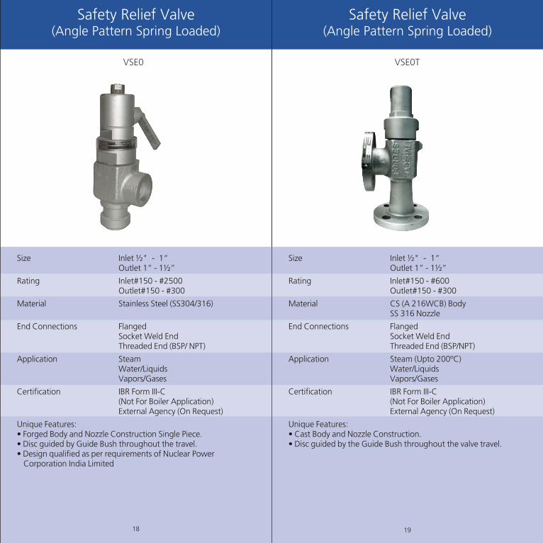
Safety Relief Valve(Angle Pattern Spring Loaded)
Size Inlet " - 1“Outlet 1” - 1Ω”
Rating Inlet#150 - #2500Outlet#150 - #300
Material Stainless Steel (SS304/316)
End Connections FlangedSocket Weld EndThreaded End (BSP/ NPT)
Application Steam Water/Liquids Vapors/Gases
Certification IBR Form III-C(Not For Boiler Application)External Agency (On Request)
Unique Features: • Forged Body and Nozzle Construction Single Piece.• Disc guided by Guide Bush throughout the travel. • Design qualified as per requirements of Nuclear Power Corporation India Limited
Ω
VSE0
18
Safety Relief Valve (Angle Pattern Spring Loaded)
Size Inlet " - 1“Outlet 1” - 1Ω”
Rating Inlet#150 - #600Outlet#150 - #300
Material CS (A 216WCB) BodySS 316 Nozzle
End Connections FlangedSocket Weld EndThreaded End (BSP/NPT)
Application Steam (Upto 200ºC)Water/Liquids Vapors/Gases
Certification IBR Form III-C(Not For Boiler Application)External Agency (On Request)
Unique Features: • Cast Body and Nozzle Construction. • Disc guided by the Guide Bush throughout the valve travel.
Ω
VSE0T
19

Size 1"-24"Rating Upto #2500Material Carbon Steel
Alloy SteelStainless SteelHastalloy, Monel, Duplex Steel on request
End Connection Flanged, Butt WeldSocket Weld (Sizes<2")
Application Steam, Water, GasesLiquids , Oil etc
Certification IBR Form III-CAPI 600/6D
Operation Electric MotorPneumatic-PistonHydraulicHand wheel
Unique Features• Available in Cast and Forged Material Of Construction• Body Guided Flexible Wedge/Parallel Slide Construction• Pressure seal Bonnet for ratings #900 & higher• Wedges and Seat designed to ensure excellent leak tightness
Gate Valve
20
Size 1"-24"Rating Upto #2500Material Carbon Steel
Alloy SteelStainless SteelHastalloy, Monel, Duplex Steel on request
End Connection Flanged, Butt WeldSocket Weld (Sizes<2")
Application Steam, Water, GasesLiquids , Oil etc
Certification IBR Form III-CAPI 6D
Operation Electric MotorPneumatic-PistonHydraulicHand wheel
Unique Features• Available in Cast and Forged Material Of Construction• Special Latern Ring arrangement possible in Gland Section• Pressure seal Bonnet for ratings #900 & higher• Special Parabolic Plug arrangement for Throttle Service
Globe Valve
21

Size 1"-24"Rating Upto #2500Material Carbon Steel
Alloy SteelStainless SteelHastalloy, Monel, Duplex Steel on request
End Connection Flanged, Butt WeldSocket Weld (Sizes<2")
Application Steam, Water, GasesLiquids , Oil etc
Certification IBR Form III-CAPI 6D
Operation Pneumatic-PistonCounter WeightSelf Actuation
Unique Features• Available in Cast and Forged Material Of Construction• Body enclosed Hinge Pin arrangement possible on request.• Pressure seal cover arrangement for ratings #900 & higher
Size 1/2"-24"Rating Upto #2500Material Carbon Steel
Alloy SteelStainless SteelHastalloy, Monel, Duplex Steel on request
End Connection Flanged, Butt WeldSocket Weld (Sizes<2")
Application Steam, Water, GasesLiquids , Oil etc
Certification IBR Form III-CAPI 6D
Operation Pneumatic-PistonHydraulicLever
Unique Features• Available in Cast and Forged Material Of Construction• Spring Loaded Seat Rings and soft seat option available for excellent seat tightness• Pressure seal Bonnet for ratings #900 & higher• Arrangement for Injection of grease.• Special coating for ball for erosive service
Ball Valve (Floating,Top Entry ,Trunion)Swing Check Valve
22 23

High Pressure Control Valve #2500
Size 2" upto 18”Rating #2500 and Higher
Material Carbon Steel (A216 WCB)Alloy Steel (A 217 WC6/WC9
End Connection Flanged EndButt Weld End
Application Feed WaterSteam
Certification IBR Form III-CExt. Agency (On Request)
Operation Pneumatic -PistonHydraulicElectrical
Unique Features: • Forged (upto 2"Size)/ Cast construction body.• Guided Multi Stage Trim to handle vibration and Noise.• Excellent Leak Tightness at valve seat.• Trim material suitable to handle erosion.
24
Size 1/2"-8"Rating Upto #2500 in sizes upto 2".
Upto #600 in Higher sizes.Material Carbon Steel
Stainless SteelEnd Connection Flanged, Butt Weld
Socket Weld (Sizes<2")Application Steam, Water, Gases,
Liquids , etcCertification
Operation Pneumatic-PistonHand WheelElectric Motor
Unique Features• Available in Cast and Forged Material Of Construction.• Unique Non Rotating Stem Design for minimal bellow failure.• Port designed to ensure no retention of process fluid on the outlet side once the valve closed.• Bellows Tested for 5000 Cycles for Critical application.• Back up Gland Packing arrangement in addition to Bellows.• Bellows internally supported to avoid mechanical failures.
Bellow Sealed Globe Valve
25

H.P. Spray Control Valve/Stop Valve(Straight and Angle pattern)
Size Inlet : " - 6”Control Range 1:50 Rating #150 - #2500Characteristic Linear /Equal %Material Carbon Steel (A105)
Low Alloy Steel (A 182 F1)Medium Alloy Steel (A 182F11/F22)
End Connections FlangedSocket Weld EndButt Weld End
Application SteamVapors /Gases
Certification IBR Form III-CExternal Agency (On Request)
Operation Pneumatic Piston CylinderHydraulic Actuator
Unique Features: • Cast/ Forged material Inline and Angle pattern Valves guided stem designed specially to handle high cavitation and flashing medium. • Seating area of Stem and Seat specially hardened with Stellite to handle high erosion due to cavitation and flashing.• Multistage Parabolic trim for high pressure reduction service.
Ω
27
Turbine Bypass Valve (Imported)( H.P. / I.P. / L.P. Bypass Valves)
(Angle Pattern /Z Pattern)
Size Inlet : 2" - 18”Outlet : upto 32”
Rating Inlet #150 - #4500Characteristic Linear/Modified Linear Material Carbon Steel (A105)
Low Alloy Steel (A 182 F1)Medium Alloy Steel (A 182F11/F22)High Alloy Steel (A 182F91)
End Connections FlangedButt Weld End
Application SteamVapors /Gases
Certification IBR Form III-C(Attested by TUVe/ LLoyds)External Agency (On Request)
Operation Pneumatic Piston CylinderHydraulic Actuator
Unique Features: • Complete Forged Construction.• Patented and proven design wherein valve outlet section preheated by steam exiting past the seat. • Assured leak tightness of Class V. • On customer request Stop Valve in Combination to Pressure Reduction Valve can be offered. • Turn down Ration 1:100 • Short length required to achieve evaporation and complete mixing of Spray Water and Steam. • Unique Spray water Injection system ensure no Thermal Shock when valve is operated. • System works equally well with Low spray water pressure as well. • Valve End to End Distance and Pipe ends can be made to suit existing pipe line. • Available in “Z” pattern on request.
DSV
26

H.P. Heater Bypass Valves (Imported)(2 Way and 3 Way Valves)
Also know as H.P. Heater Bypass or Group Bypass Valves.
Size Inlet : 4"OnwardsOutlet : 4” onwards
Rating Inlet #150 - #2500
Material Carbon Steel (A105)Low Alloy Steel (A 182 F1)Medium Alloy Steel (A 182F11/F22)
End Connections FlangedButt Weld End
Application Feed Water Heater BypassCertification IBR Form III-C
(Attested by TUVe/ LLoyds)External Agency (On Request)
Operation Medium OperatedElectrical Actuator
Unique Features: • Complete Cast/ Forged Construction.• Bypasses H.P. Feed Water Heater automatically in event of rupture in Heater tubes.• Valve medium operated.
28
Start Up and Vent Valve(Angle pattern/ Z Pattern)
Size Inlet : 2"- 6”
Rating #900 - #4500Characteristic Linear/Equal%Material Carbon Steel (A105)
Low Alloy Steel (A 182 F1)Medium Alloy Steel (A 182F11/F22)High Alloy Steel (A 182F91)
End Connections FlangedButt Weld End
Application Steam+WaterCertification IBR Form III-C
(Attested by TUVe/ LLoyds)External Agency (On Request)
Operation Pneumatic OperatedElectrical Actuator
Unique Features: • Complete Forged Construction. • Complete guided parabolic or multistage plug. • Seating area of Stem and Seat specially hardened with Stellite to handle high erosion due to cavitation and flashing.
29

Size Rating Schedule Pipe OD (ØF) (t) (ØG)
15 150 SCH STD 21.3 2.77 15.7615 150 SCH 40 21.3 2.77 15.7615 300 SCH STD 21.3 2.77 15.7615 300 SCH 40 21.3 2.77 15.7615 300 SCH XS 21.3 3.73 13.8415 300 SCH 80 21.3 3.73 13.8425 150 SCH STD 33.4 3.38 26.6425 150 SCH 40 33.4 3.38 26.6425 300 SCH STD 33.4 3.38 26.6425 300 SCH 40 33.4 3.38 26.6425 300 SCH XS 33.4 4.55 24.325 300 SCH 80 33.4 4.55 24.325 600 SCH STD 33.4 3.38 26.6425 600 SCH 40 33.4 3.38 26.6425 600 SCH XS 33.4 4.55 24.325 600 SCH 80 33.4 4.55 24.325 900 SCH STD 33.4 3.38 26.6425 900 SCH 40 33.4 3.38 26.6425 900 SCH XS 33.4 4.55 24.325 900 SCH 80 33.4 4.55 24.325 1500 SCH STD 33.4 3.38 26.6425 1500 SCH 40 33.4 3.38 26.6425 1500 SCH XS 33.4 4.55 24.325 1500 SCH 80 33.4 4.55 24.325 1500 SCH 160 33.4 6.35 20.725 1500 SCH XXS 33.4 9.09 15.2225 2500 SCH STD 33.4 3.38 26.6425 2500 SCH 40 33.4 3.38 26.6425 2500 SCH XS 33.4 4.55 24.325 2500 SCH 80 33.4 4.55 24.325 2500 SCH 160 33.4 6.35 20.725 2500 SCH XXS 33.4 9.09 15.22
Pipe Thickness Pipe ID
Pipe End details
30
±0.8
1.6
37.5º±2.5º
ØF
ØG
t
Size Rating Schedule Pipe OD Pipe Thickness Pipe ID (ØF) (t) (ØG)
40 150 SCH STD 48.3 3.68 40.9440 150 SCH 40 48.3 3.68 40.9440 300 SCH STD 48.3 3.68 40.9440 300 SCH 40 48.3 3.68 40.9440 300 SCH XS 48.3 5.08 38.1440 300 SCH 80 48.3 5.08 38.1450 150 SCH STD 60.3 3.91 52.4850 150 SCH 40 60.3 3.91 52.4850 300 SCH STD 60.3 3.91 52.4850 300 SCH 40 60.3 3.91 52.4850 300 SCH XS 60.3 5.54 49.2250 300 SCH 80 60.3 5.54 49.2250 600 SCH STD 60.3 3.91 52.4850 600 SCH 40 60.3 3.91 52.4850 600 SCH XS 60.3 5.54 49.2250 600 SCH 80 60.3 5.54 49.2250 900 SCH STD 60.3 3.91 52.4850 900 SCH 40 60.3 3.91 52.4850 900 SCH XS 60.3 5.54 49.2250 900 SCH 80 60.3 5.54 49.2250 1500 SCH STD 60.3 3.91 52.4850 1500 SCH 40 60.3 3.91 52.4850 1500 SCH XS 60.3 5.54 49.2250 1500 SCH 80 60.3 5.54 49.2250 1500 SCH 160 60.3 8.74 42.8250 1500 SCH XXS 60.3 11.07 38.1650 2500 SCH STD 60.3 3.91 52.4850 2500 SCH 40 60.3 3.91 52.4850 2500 SCH XS 60.3 5.54 49.2250 2500 SCH 80 60.3 5.54 49.2250 2500 SCH 160 60.3 8.74 42.8250 2500 SCH XXS 60.3 11.07 38.1680 150 SCH STD 88.9 5.49 77.9280 150 SCH 40 88.9 5.49 77.9280 300 SCH STD 88.9 5.49 77.9280 300 SCH 40 88.9 5.49 77.9280 300 SCH XS 88.9 7.62 73.6680 300 SCH 80 88.9 7.62 73.6680 600 SCH STD 88.9 5.49 77.9280 600 SCH 40 88.9 5.49 77.9280 600 SCH XS 88.9 7.62 73.6680 600 SCH 80 88.9 7.62 73.6680 900 SCH STD 88.9 5.49 77.9280 900 SCH 40 88.9 5.49 77.9280 900 SCH XS 88.9 7.62 73.6680 900 SCH 80 88.9 7.62 73.6680 1500 SCH STD 88.9 5.49 77.9280 1500 SCH 40 88.9 5.49 77.9280 1500 SCH XS 88.9 7.62 73.6680 1500 SCH 80 88.9 7.62 73.6680 1500 SCH 160 88.9 11.13 66.6480 1500 SCH XXS 88.9 15.24 58.42
31

Size Sch 40 Sch 80 Sch 160 Sch XXS
D S T D S T D S T D S T
3/8"(10) 11.7 20 3.5 9.9 20 5 - - - - - -
1/2" (15) 15.7 24 4.5 13.9 24 6 11.8 24 7 6.4 24 11.5
3/4" (20) 20.9 30 5 18.8 30 6 15.6 30 8.5 11.0 30 12
1" (25) 26.6 37 5 24.3 37 7 20.7 37 9.5 15.2 37 14
1 1/4" (32) 35.1 45 5 32.5 45 7.5 29.5 45 10 22.8 45 15
1 1/2" (40) 40.9 51 6 38.1 51 8 34 51 11 27.9 51 15.5
2" (50) 52.5 65 6 49.3 65 8.5 42.9 65 13 38.2 65 17
2 1/2" (65) 62.7 80 8 59 80 11 54 80 14.5 45.0 80 21
3"(80) 77.9 95 8 73.7 95 11.5 66.6 95 17 58.4 95 23
Butt Weld Acc. ANSI B 16.25
68º
45º
37.5º
D S
T
1.6
± 0.
8
T
SD
Size(DN) Sch 40 Sch 80 Sch 160 Sch XXS
D S T D S T D S T D S T
3/8"(10) 11.7 17.5 10 9.9 17.5 10 - - - - - -
1/2" (15) 15.7 22 10 13.9 22 10 11.8 22 10 6.4 22 10
3/4" (20) 20.9 27 13 18.8 27 13 15.6 27 13 11 27 13
1" (25) 26.6 33.8 13 24.3 33.8 13 20.7 33.8 13 15.2 33.8 13
1 1/4" (32) 35.1 42.7 13 32.5 42.7 13 29.5 42.7 13 22.8 42.7 13
1 1/2" (40) 40.9 48.6 13 38.1 48.6 13 34 48.6 13 27.9 48.6 13
2" (50) 52.5 61.1 16 49.3 61.1 16 42.9 61.1 16 38.2 61.1 16
2 1/2" (65) 62.7 74 16 59 74 16 54 74 16 45 74 16
3"(80) 77.9 90 16 73.7 90 16 66.6 90 16 58.4 90 16
Socket Weld Acc. ANSI B 16.11
Valve End details
32
Size Sch 40 Sch 80 Sch 160 Sch XXS
D S T D S T D S T D S T
3/8"(10) 11.7 20 3.5 9.9 20 5 - - - - - -
1/2" (15) 15.7 24 4.5 13.9 24 6 11.8 24 7 6.4 24 11.5
3/4" (20) 20.9 30 5 18.8 30 6 15.6 30 8.5 11.0 30 12
1" (25) 26.6 37 5 24.3 37 7 20.7 37 9.5 15.2 37 14
1 1/4" (32) 35.1 45 5 32.5 45 7.5 29.5 45 10 22.8 45 15
1 1/2" (40) 40.9 51 6 38.1 51 8 34 51 11 27.9 51 15.5
2" (50) 52.5 65 6 49.3 65 8.5 42.9 65 13 38.2 65 17
2 1/2" (65) 62.7 80 8 59 80 11 54 80 14.5 45.0 80 21
3"(80) 77.9 95 8 73.7 95 11.5 66.6 95 17 58.4 95 23
Butt Weld Acc. ANSI B 16.25
Size(DN) Sch 40 Sch 80 Sch 160 Sch XXS
D S T D S T D S T D S T
3/8"(10) 11.7 17.5 10 9.9 17.5 10 - - - - - -
1/2" (15) 15.7 22 10 13.9 22 10 11.8 22 10 6.4 22 10
3/4" (20) 20.9 27 13 18.8 27 13 15.6 27 13 11 27 13
1" (25) 26.6 33.8 13 24.3 33.8 13 20.7 33.8 13 15.2 33.8 13
1 1/4" (32) 35.1 42.7 13 32.5 42.7 13 29.5 42.7 13 22.8 42.7 13
1 1/2" (40) 40.9 48.6 13 38.1 48.6 13 34 48.6 13 27.9 48.6 13
2" (50) 52.5 61.1 16 49.3 61.1 16 42.9 61.1 16 38.2 61.1 16
2 1/2" (65) 62.7 74 16 59 74 16 54 74 16 45 74 16
3"(80) 77.9 90 16 73.7 90 16 66.6 90 16 58.4 90 16
Socket Weld Acc. ANSI B 16.11
Valve End details
33

35
38 50 100 150 200 250 300 350 375 400 425 450 475 500 525 550 575 600Class
A 105 19 19 17 15 13 12 10 8 7 6 5A 182F22 19 19 17 15 13 12 10 8 7 6 5 4 3 2 1 1 1A 182F91 19 19 17 15 13 12 10 8 7 6 5 4 3 2 1 1 1 1
F 316 18 18 16 14 13 12 10 8 7 6 5 4 3 2 1A 105 51 50 46 45 43 41 38 36 36 34 28
A 182F22 51 51 51 50 48 46 42 40 38 36 35 33 31 27 21 15 10A 182F91 51 51 51 50 48 46 42 40 38 36 35 33 31 28 25 25 23 19
F 316 49 48 42 38 35 33 31 30 29 29 28 28 28 27 25A 105 102 100 92 90 87 83 77 73 72 69 57
A 182F22 103 103 103 100 97 92 85 80 77 73 70 67 63 55 43 30 21A 182F91 103 103 103 100 97 92 85 80 77 73 70 67 63 56 51 49 46 39
F 316 99 96 84 77 71 68 63 61 59 58 58 57 57 54 50
Pressure (kg/cm≤)
A 105 136 133 123 120 116 111 103 98 97 91 76A 182F22 137 137 137 133 129 123 114 107 103 97 93 90 84 74 57 40 28A182F91 137 137 137 133 129 123 114 107 103 97 93 90 84 75 68 66 62 52
F316 132 128 112 102 95 89 84 81 79 78 77 76 76 72 67A 105 255 250 231 225 219 208 193 184 182 172 143
A 182F22 258 258 257 250 243 230 214 201 194 183 175 169 158 138 108 76 52A182F91 258 258 257 250 243 230 214 201 194 183 175 169 158 140 128 124 117 97
F316 248 240 210 192 178 166 158 152 149 147 145 144 143 136 126A 105 289 283 262 256 246 236 219 209 206 195 163
A 182F22 292 292 291 284 276 262 242 227 219 207 198 191 179 157 122 87 59A182F91 292 292 291 284 276 262 242 227 219 207 198 191 179 159 146 141 132 110
F316 281 272 239 218 202 189 179 172 169 166 165 163 162 154 143A 105 425 417 386 376 365 347 322 307 303 287 239
A 182F22 430 430 429 418 406 386 357 335 323 304 292 281 263 231 180 127 87A182F91 430 430 429 418 406 386 357 335 323 304 292 281 263 234 214 207 195 162
F316 413 400 351 320 297 278 263 253 248 245 242 240 238 227 210A 105 459 450 417 406 394 375 348 332 326 310 258
A 182F22 465 465 463 451 438 416 385 362 349 329 315 304 284 250 194 138 94A182F91 465 465 463 451 438 416 385 362 349 329 315 304 284 253 232 224 211 175
F316 446 432 379 346 320 300 284 274 268 264 262 259 257 246 227A 105 765 750 695 678 657 625 580 551 546 517 431
A 182F22 775 775 772 752 731 694 642 603 581 548 526 506 474 417 325 230 157A182F91 775 775 772 752 731 694 642 603 581 548 526 506 474 422 386 374 351 292
F316 744 721 632 577 534 500 474 456 448 441 436 432 430 410 378
34
Temperature / Pressure Chart
Temperature (ºC)
150
300
600
38 50 100 150 200 250 300 350 375 400 425 450 475 500 525 550 575 600Class
A 105 19 19 17 15 13 12 10 8 7 6 5A 182F22 19 19 17 15 13 12 10 8 7 6 5 4 3 2 1 1 1A 182F91 19 19 17 15 13 12 10 8 7 6 5 4 3 2 1 1 1 1
F 316 18 18 16 14 13 12 10 8 7 6 5 4 3 2 1A 105 51 50 46 45 43 41 38 36 36 34 28
A 182F22 51 51 51 50 48 46 42 40 38 36 35 33 31 27 21 15 10A 182F91 51 51 51 50 48 46 42 40 38 36 35 33 31 28 25 25 23 19
F 316 49 48 42 38 35 33 31 30 29 29 28 28 28 27 25A 105 102 100 92 90 87 83 77 73 72 69 57
A 182F22 103 103 103 100 97 92 85 80 77 73 70 67 63 55 43 30 21A 182F91 103 103 103 100 97 92 85 80 77 73 70 67 63 56 51 49 46 39
F 316 99 96 84 77 71 68 63 61 59 58 58 57 57 54 50
Pressure (kg/cm≤)
800
1500
1700
2500
2700
4500
A 105 136 133 123 120 116 111 103 98 97 91 76A 182F22 137 137 137 133 129 123 114 107 103 97 93 90 84 74 57 40 28A182F91 137 137 137 133 129 123 114 107 103 97 93 90 84 75 68 66 62 52
F316 132 128 112 102 95 89 84 81 79 78 77 76 76 72 67A 105 255 250 231 225 219 208 193 184 182 172 143
A 182F22 258 258 257 250 243 230 214 201 194 183 175 169 158 138 108 76 52A182F91 258 258 257 250 243 230 214 201 194 183 175 169 158 140 128 124 117 97
F316 248 240 210 192 178 166 158 152 149 147 145 144 143 136 126A 105 289 283 262 256 246 236 219 209 206 195 163
A 182F22 292 292 291 284 276 262 242 227 219 207 198 191 179 157 122 87 59A182F91 292 292 291 284 276 262 242 227 219 207 198 191 179 159 146 141 132 110
F316 281 272 239 218 202 189 179 172 169 166 165 163 162 154 143A 105 425 417 386 376 365 347 322 307 303 287 239
A 182F22 430 430 429 418 406 386 357 335 323 304 292 281 263 231 180 127 87A182F91 430 430 429 418 406 386 357 335 323 304 292 281 263 234 214 207 195 162
F316 413 400 351 320 297 278 263 253 248 245 242 240 238 227 210A 105 459 450 417 406 394 375 348 332 326 310 258
A 182F22 465 465 463 451 438 416 385 362 349 329 315 304 284 250 194 138 94A182F91 465 465 463 451 438 416 385 362 349 329 315 304 284 253 232 224 211 175
F316 446 432 379 346 320 300 284 274 268 264 262 259 257 246 227A 105 765 750 695 678 657 625 580 551 546 517 431
A 182F22 775 775 772 752 731 694 642 603 581 548 526 506 474 417 325 230 157A182F91 775 775 772 752 731 694 642 603 581 548 526 506 474 422 386 374 351 292
F316 744 721 632 577 534 500 474 456 448 441 436 432 430 410 378

ASTM Material
Forging Casting
A 105 A 216 WCBA 182-F11 A 217 WC6A 182-F22 A 217 WC9A182-F304 A 351 CF8A182-F316 A 351 CF8MA182-F304L A351 CF3A182-F316L A351 CF3M
DIN Material - Close equivalent ASTM MaterialsForgings
C 22.8 A10515Mo3 A182 F1 13CrMo44 A182F1110CrMo910 A182F22X5CrNiMo17122 A182F316X5CrNiMo1810 A182F304X6CrNiTi1810 A182F321X20CrNi172 A276 431X10Cr13 A276 410
DIN Material - Equivalent AISI
1.4057 AISI 4311.4125 AISI 440C1.4301 AISI 3041.4307 AISI 304L1.4401 AISI 3161.4404 AISI 316L1.4541 AISI 3211.4006 AISI 4101.4542 AISI 630
Material Equivalents
36
#150 - Body : 30 kg/cm≤- Seat : 22 kg/cm≤
#300 - Body : 77 kg/cm≤- Seat : 57 kg/cm≤
#600 - Body : 157 kg/cm≤- Seat : 115 kg/cm≤
#800 - Body : 210 kg/cm≤- Seat : 153 kg/cm≤
#1500 - Body : 396 kg/cm≤- Seat : 291 kg/cm≤
#2500 - Body : 660 kg/cm≤- Seat : 484 kg/cm≤
Hydro Test Pressure
No1:-(F6) - Stem:410/Seat:410/Disc:410
No 2:-(304) - Stem:304/Seat:304/Disc:304
No 5:-(HF) - Stem: 410/Seat: 410+St.6/Seat:410+St6
No.8:-(F6HF) - Stem :410/Seat:410+St 6/Disc :410
No 10:-(316) - Stem:316/Seat:316/Disc:316
No.12:-(316HFS) - Stem 316/Seat :316+St6/Disc:316
No15:-(304HF) - Stem 304/Seat:304+St6/Disc:304+St6
No16:-(316HF) - Stem316HF/Seat:316+St6/Dis:316+St6
Trim Specifications
37

Set Pressure: Pressure at which valve starts opening or leaking
Back Pressure: Pressure at the outlet side of valve
Built Up Back Pressure: Pressure at valve outlet flangeproduced by blow off and frictional losses due to flow.
Super imposed Back Pressure: Pressure at valve outlet flange when valve is closed
Reseat Pressure: Pressure at which valve closes and there is no further leakage through valve seat
Blowdown: Difference between Set Pressure and Reseat Pressure. Expressed in percentage of set pressure.
Overpressure: Increase of Pressure over the set pressure at which valve discharges its rated capacity
Accumulation: Pressure Increase above Max. allowable Working Pressure of Vessel during discharge through pressure relief valve.
Cold Differential Test Pressure: Pressure at which valve is adjusted to open on Test Stand.
Simmer: Audible passage of Gas or Vapour across valve seat prior to pop up.
Chatter or Flutter: Rapid Opening and closing of valve characterized by audible noise of impact of Disc on valveseat at a high frequency.
Maximum Allowable Working Pressure: Maximum Gauge pressure permissible in a vessel at the designated temperature. A vessel may not be operated above this pressure or its equivalent metal temperature. It is the highest pressure at which primary Safety valve is set to open.
Actual Capacity: This is the capacity determined by actual measurement using steam as medium.
Certified Capacity: This is the actual capacity derated by 10%
Safety Valve Terminology
38
Nozzle Discharge Co-Efficient (K): Actual Flow divided by theoretical flow for the same nozzle with no flow loss .
Important Notes related to Safety Valves: Valve actual Orifice Area (A) and Advertised Orifice Area are not the same for most manufacturers. The Actual orifice area of nozzle are higher than the advertised area's and the variation is between 10% to 25%.
In the year 1962, ASME code was amended requiring all Safety Valve manufacturers to derate their valve relieving capacities by 10%. Most manufacturers chose to increase the nozzle area's to maintain the same K*A .
However the advertised API Orifice area's continue to be maintained by most manufacturers. The value of K*A for all manufacturers however is equal to or slightly lower than the National Board listings.
39
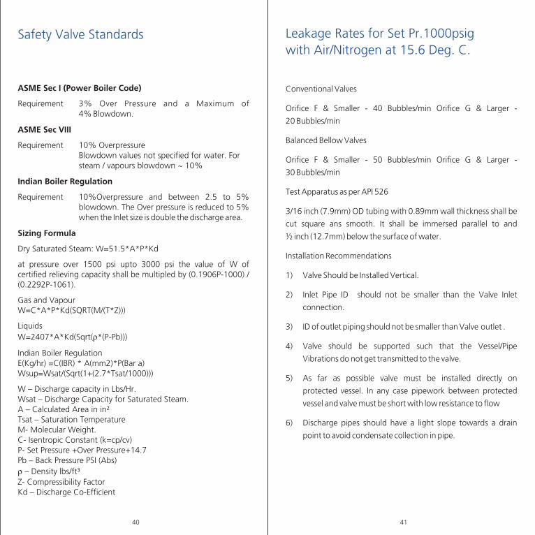
Safety Valve Standards
ASME Sec I (Power Boiler Code)
Requirement 3% Over Pressure and a Maximum of 4% Blowdown.
ASME Sec VIII
Requirement 10% Overpressure Blowdown values not specified for water. For steam / vapours blowdown ~ 10%
Indian Boiler Regulation
Requirement 10%Overpressure and between 2.5 to 5% blowdown. The Over pressure is reduced to 5% when the Inlet size is double the discharge area.
Sizing Formula
Dry Saturated Steam: W=51.5*A*P*Kd
at pressure over 1500 psi upto 3000 psi the value of W of certified relieving capacity shall be multipled by (0.1906P-1000) / (0.2292P-1061).
Gas and VapourW=C*A*P*Kd(SQRT(M/(T*Z)))
LiquidsW=2407*A*Kd(Sqrt(r*(P-Pb)))
Indian Boiler RegulationE(Kg/hr) =C(IBR) * A(mm2)*P(Bar a)Wsup=Wsat/(Sqrt(1+(2.7*Tsat/1000)))
W – Discharge capacity in Lbs/Hr.Wsat – Discharge Capacity for Saturated Steam.A – Calculated Area in in≤Tsat – Saturation TemperatureM- Molecular Weight.C- Isentropic Constant (k=cp/cv)P- Set Pressure +Over Pressure+14.7Pb – Back Pressure PSI (Abs)r – Density lbs/ft≥Z- Compressibility FactorKd – Discharge Co-Efficient
40
Conventional Valves
Orifice F & Smaller - 40 Bubbles/min Orifice G & Larger - 20 Bubbles/min
Balanced Bellow Valves
Orifice F & Smaller - 50 Bubbles/min Orifice G & Larger - 30 Bubbles/min
Test Apparatus as per API 526
3/16 inch (7.9mm) OD tubing with 0.89mm wall thickness shall be cut square ans smooth. It shall be immersed parallel to and Ω inch (12.7mm) below the surface of water.
Installation Recommendations
1) Valve Should be Installed Vertical.
2) Inlet Pipe ID should not be smaller than the Valve Inlet connection.
3) ID of outlet piping should not be smaller than Valve outlet .
4) Valve should be supported such that the Vessel/Pipe Vibrations do not get transmitted to the valve.
5) As far as possible valve must be installed directly on protected vessel. In any case pipework between protected vessel and valve must be short with low resistance to flow
6) Discharge pipes should have a light slope towards a drain point to avoid condensate collection in pipe.
Leakage Rates for Set Pr.1000psigwith Air/Nitrogen at 15.6 Deg. C.
41
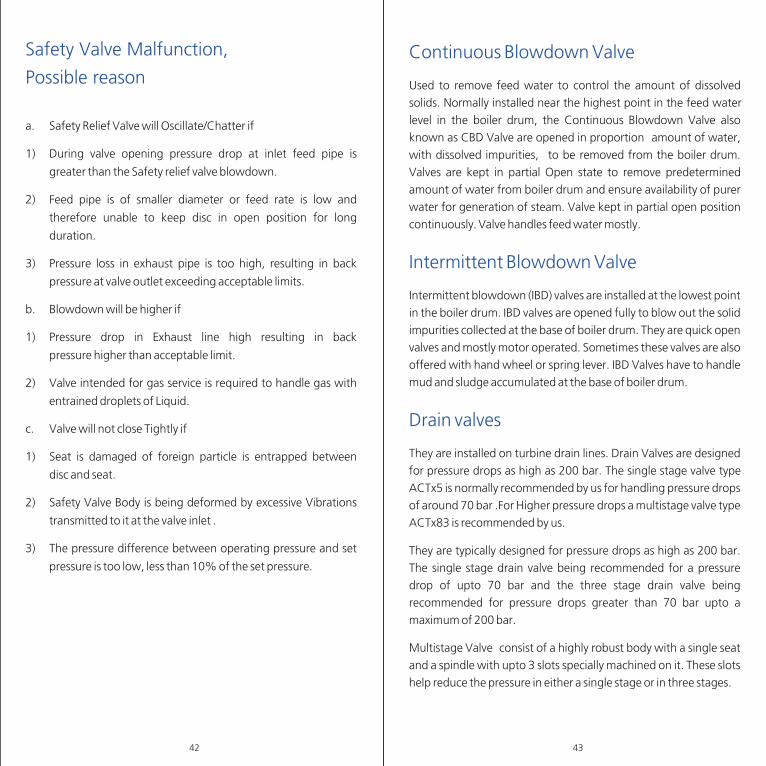
a. Safety Relief Valve will Oscillate/Chatter if
1) During valve opening pressure drop at inlet feed pipe is greater than the Safety relief valve blowdown.
2) Feed pipe is of smaller diameter or feed rate is low and therefore unable to keep disc in open position for long duration.
3) Pressure loss in exhaust pipe is too high, resulting in back pressure at valve outlet exceeding acceptable limits.
b. Blowdown will be higher if
1) Pressure drop in Exhaust line high resulting in back pressure higher than acceptable limit.
2) Valve intended for gas service is required to handle gas with entrained droplets of Liquid.
c. Valve will not close Tightly if
1) Seat is damaged of foreign particle is entrapped between disc and seat.
2) Safety Valve Body is being deformed by excessive Vibrations transmitted to it at the valve inlet .
3) The pressure difference between operating pressure and set pressure is too low, less than 10% of the set pressure.
Safety Valve Malfunction, Possible reason
42
Continuous Blowdown Valve
Intermittent Blowdown Valve
Used to remove feed water to control the amount of dissolved solids. Normally installed near the highest point in the feed water level in the boiler drum, the Continuous Blowdown Valve also known as CBD Valve are opened in proportion amount of water, with dissolved impurities, to be removed from the boiler drum. Valves are kept in partial Open state to remove predetermined amount of water from boiler drum and ensure availability of purer water for generation of steam. Valve kept in partial open position continuously. Valve handles feed water mostly.
Intermittent blowdown (IBD) valves are installed at the lowest point in the boiler drum. IBD valves are opened fully to blow out the solid impurities collected at the base of boiler drum. They are quick open valves and mostly motor operated. Sometimes these valves are also offered with hand wheel or spring lever. IBD Valves have to handle mud and sludge accumulated at the base of boiler drum.
They are installed on turbine drain lines. Drain Valves are designed for pressure drops as high as 200 bar. The single stage valve type ACTx5 is normally recommended by us for handling pressure drops of around 70 bar .For Higher pressure drops a multistage valve type ACTx83 is recommended by us.
They are typically designed for pressure drops as high as 200 bar. The single stage drain valve being recommended for a pressure drop of upto 70 bar and the three stage drain valve being recommended for pressure drops greater than 70 bar upto a maximum of 200 bar.
Multistage Valve consist of a highly robust body with a single seat and a spindle with upto 3 slots specially machined on it. These slots help reduce the pressure in either a single stage or in three stages.
Drain valves
43
Designed for Handling clean condensate and /or steam. Turbine Drain Control, Reheater Drain Lines etc are some of the applications for these valves. Valves have to handle High Pressure drops when opened and maintain good leak tightness at seat when closed. Conventional Globe valve cannot handle such an application and fail after a few operation. Pressure reduction in Multiple Stage and increased resistance to flow in its passage towards the outlet helps to minimize harmful effects of Cavitation and Flashing enhancing seat life.
Lift Check valves essentially consist of forged body and forged cover bolted on to the body. These are basically one way flow type of valves i.e. non return type. Under pressure of the incoming fluid, the disc will lift permitting the flow to take place through the valve. However, any attempt by the medium to enter the valve will result in the disc coming in the way of the reversing flow, thus shutting off its movement towards the valve inlet the valve will not be successful as the lift disc comes in its path and the reversing medium itself helps to push the disc onto the valve seat ,thus shutting off its movement towards the valve inlet. Such a valve is normally used at the outlet of Chemical Dosing pump etc. Sometimes a combination of Stop Valve with Lift Check Valve called "Stop Cum Check Valve or Screwed Down Non Return Valve" is also used on the pump outlet.
Lift check valves
44
Notes
45

Notes
46
Notes
47