valve terminal type 03/04−b - festo · valves, 5/2−way double−solenoid valves, 5/3−way...
TRANSCRIPT
Electronics
Manual
Valve terminal with
field bus connection
module for
DeviceNet
Typ IDN−03−8A
Manual
193 644 GB
0503a
Valve terminal type 03/04−B


Contents and general safety instructions
IFesto P.BE−VIDN−03−8A−GB 0503a
Author S. Breuer. . . . . . . . . . . . . . . . . . . . . . . . . . . . . . . . . .
Editors H.�J. Drung, M.Holder. . . . . . . . . . . . . . . . . . . . . . . .
Translation D. Smith. . . . . . . . . . . . . . . . . . . . . . . . . . . . . . . .
Layout Festo AG & Co., Dept. KG−GD. . . . . . . . . . . . . . . . . .
Type setting KI−TD. . . . . . . . . . . . . . . . . . . . . . . . . . . . . . . . .
Edition 0503a. . . . . . . . . . . . . . . . . . . . . . . . . . . . . . . . . . . . .
Title Manual. . . . . . . . . . . . . . . . . . . . . . . . . . . . . . . . . . . . . .
Designation P.BE−VIDN−03−8A−GB. . . . . . . . . . . . . . . . . . . .
Order no. 193 644 GB. . . . . . . . . . . . . . . . . . . . . . . . . . . . . .
E (Festo AG�&�Co., D�73726 Esslingen,
Federal Republic of Germany, 2000)
Internet: http://www.festo.com
E−Mail: [email protected]
The copying, distribution and utilization of this document
as well as the communication of its contents to others
without expressed authorization is prohibited. Offenders
will be held liable for the payment of damages. All rights
reserved, in particular the right to carry out patent, utility
model or ornamental design registration.

Contents and general safety instructions
II Festo P.BE−VIDN−03−8A−GB 0503a

Contents and general safety instructions
IIIFesto P.BE−VIDN−03−8A−GB 0503a
Contents
Designated use V. . . . . . . . . . . . . . . . . . . . . . . . . . . . . . . . . . . . . . . . . . . . . . . . . . . . . . . .
Target group VI. . . . . . . . . . . . . . . . . . . . . . . . . . . . . . . . . . . . . . . . . . . . . . . . . . . . . . . . . .
Service VI. . . . . . . . . . . . . . . . . . . . . . . . . . . . . . . . . . . . . . . . . . . . . . . . . . . . . . . . . . . . . . .
Important user instructions VII. . . . . . . . . . . . . . . . . . . . . . . . . . . . . . . . . . . . . . . . . . . . . .
Abbreviations IX. . . . . . . . . . . . . . . . . . . . . . . . . . . . . . . . . . . . . . . . . . . . . . . . . . . . . . . . .
Representing the valve terminal in this manual X. . . . . . . . . . . . . . . . . . . . . . . . . . . . . .
Other manuals for this valve terminal XI. . . . . . . . . . . . . . . . . . . . . . . . . . . . . . . . . . . . . .
1. System summary 1−1. . . . . . . . . . . . . . . . . . . . . . . . . . . . . . . . . . . . . . . . . . . . . . .
1.1 Summary of the valve terminal 1−3. . . . . . . . . . . . . . . . . . . . . . . . . . . . . . . . . . . .
1.2 Description of the components 1−5. . . . . . . . . . . . . . . . . . . . . . . . . . . . . . . . . . . .
1.3 Method of operation 1−9. . . . . . . . . . . . . . . . . . . . . . . . . . . . . . . . . . . . . . . . . . . .
2. Fitting 2−1. . . . . . . . . . . . . . . . . . . . . . . . . . . . . . . . . . . . . . . . . . . . . . . . . . . . . . . .
2.1 Fitting the modules and components 2−3. . . . . . . . . . . . . . . . . . . . . . . . . . . . . . .
2.1.1 Internal earthing of the end plate 2−4. . . . . . . . . . . . . . . . . . . . . . . . . . . . . . . . . .
2.1.2 Hat rail clamping unit (type 03) 2−6. . . . . . . . . . . . . . . . . . . . . . . . . . . . . . . . . . . .
2.2 Fitting the valve terminal onto a wall (types 03 and 04B) 2−7. . . . . . . . . . . . . . .
2.3 Fitting onto a hat rail (type 03) 2−9. . . . . . . . . . . . . . . . . . . . . . . . . . . . . . . . . . . .
3. Installation 3−1. . . . . . . . . . . . . . . . . . . . . . . . . . . . . . . . . . . . . . . . . . . . . . . . . . .
3.1 General installation instructions 3−3. . . . . . . . . . . . . . . . . . . . . . . . . . . . . . . . . . .
3.2 Setting the node address and the field bus baud rate 3−5. . . . . . . . . . . . . . . . . .
3.3 Connecting the valve terminal 3−9. . . . . . . . . . . . . . . . . . . . . . . . . . . . . . . . . . . . .
3.3.1 Connecting cable 3−9. . . . . . . . . . . . . . . . . . . . . . . . . . . . . . . . . . . . . . . . . . . . . . .
3.3.2 Preparing the connecting cable 3−10. . . . . . . . . . . . . . . . . . . . . . . . . . . . . . . . . . . .
3.4 Selecting the power unit 3−12. . . . . . . . . . . . . . . . . . . . . . . . . . . . . . . . . . . . . . . . .
3.4.1 Ascertaining the current consumption 3−14. . . . . . . . . . . . . . . . . . . . . . . . . . . . . .
3.4.2 Connecting the load voltage for the valves 3−15. . . . . . . . . . . . . . . . . . . . . . . . . . .
3.5 Connecting the field bus 3−19. . . . . . . . . . . . . . . . . . . . . . . . . . . . . . . . . . . . . . . . .
3.5.1 Fitting a terminating resistor 3−24. . . . . . . . . . . . . . . . . . . . . . . . . . . . . . . . . . . . . .

Contents and general safety instructions
IV Festo P.BE−VIDN−03−8A−GB 0503a
4. Commissioning 4−1. . . . . . . . . . . . . . . . . . . . . . . . . . . . . . . . . . . . . . . . . . . . . . . .
4.1 Preparing the valve terminal for commissioning 4−3. . . . . . . . . . . . . . . . . . . . . .
4.1.1 Compiling the configuration list 4−3. . . . . . . . . . . . . . . . . . . . . . . . . . . . . . . . . . .
4.1.2 Address assignment of the valve terminal 4−4. . . . . . . . . . . . . . . . . . . . . . . . . . .
4.1.3 Address assignment after extension/conversion 4−7. . . . . . . . . . . . . . . . . . . . . .
4.1.4 Switching on the power supply 4−9. . . . . . . . . . . . . . . . . . . . . . . . . . . . . . . . . . . .
4.2 Commissioning on the DeviceNet 4−10. . . . . . . . . . . . . . . . . . . . . . . . . . . . . . . . . .
4.2.1 Configuring DeviceNet slave characteristics (EDS) 4−11. . . . . . . . . . . . . . . . . . . .
4.2.2 General information on parametrizing 4−13. . . . . . . . . . . . . . . . . . . . . . . . . . . . . .
4.2.3 Instructions on parametrizing with RSNetWorx for DeviceNet 4−14. . . . . . . . . . .
5. Diagnosis and error treatment 5−1. . . . . . . . . . . . . . . . . . . . . . . . . . . . . . . . . . .
5.1 Summary of diagnostic possibilities 5−3. . . . . . . . . . . . . . . . . . . . . . . . . . . . . . . .
5.1.1 Diagnosis by means of LEDs 5−4. . . . . . . . . . . . . . . . . . . . . . . . . . . . . . . . . . . . . .
5.1.2 Normal operating status 5−5. . . . . . . . . . . . . . . . . . . . . . . . . . . . . . . . . . . . . . . . .
5.1.3 Error display of the module/network status LED 5−5. . . . . . . . . . . . . . . . . . . . . .
5.1.4 LED for status display of the valve solenoid coils 5−7. . . . . . . . . . . . . . . . . . . . . .
5.1.5 Testing the valves 5−9. . . . . . . . . . . . . . . . . . . . . . . . . . . . . . . . . . . . . . . . . . . . . . .
5.1.6 Reaction to faults in the control system 5−12. . . . . . . . . . . . . . . . . . . . . . . . . . . . .
5.1.7 Diagnosis on the Allen−Bradley DeviceNet 5−13. . . . . . . . . . . . . . . . . . . . . . . . . . .
A. Technical Appendix A−1. . . . . . . . . . . . . . . . . . . . . . . . . . . . . . . . . . . . . . . . . . . . .
A.1 Accessories A−3. . . . . . . . . . . . . . . . . . . . . . . . . . . . . . . . . . . . . . . . . . . . . . . . . . . .
A.2 DeviceNet specifications for the valve terminal A−7. . . . . . . . . . . . . . . . . . . . . . .
A.2.1 Identity object: class code 01 (0x01) A−11. . . . . . . . . . . . . . . . . . . . . . . . . . . . . . .
A.2.2 Router object: class code 02 (0x02) A−13. . . . . . . . . . . . . . . . . . . . . . . . . . . . . . . .
A.2.3 DeviceNet object: class code 03 (0x03) A−13. . . . . . . . . . . . . . . . . . . . . . . . . . . . .
A.2.4 Assembly object: class code 04 (0x04) A−15. . . . . . . . . . . . . . . . . . . . . . . . . . . . . .
A.2.5 Connection object: class code 05 (0x05) A−17. . . . . . . . . . . . . . . . . . . . . . . . . . . .
A.3 Technical specifications A−25. . . . . . . . . . . . . . . . . . . . . . . . . . . . . . . . . . . . . . . . . .
A.4 Index A−29. . . . . . . . . . . . . . . . . . . . . . . . . . . . . . . . . . . . . . . . . . . . . . . . . . . . . . . . .

Contents and general safety instructions
VFesto P.BE−VIDN−03−8A−GB 0503a
Designated use
The valve terminal described in this documentation may only
be used as follows:
� for controlling pneumatic actuators on the DeviceNet
Maximum 8 valve solenoid coils can be controlled. Both MIDI
and MAXI valves (type 03) as well as ISO valves sizes 1, 2 and
3 (type 04B) can be used. Special adapter plates are required
for connecting ISO valves.
Please use the valve terminal only as follows:
� as designated
� in faultless technical condition
� without unauthorized modifications.
The specified maximum values for pressures, temperatures,
electrical data, torques, etc. must be observed when addi�
tional commercially−available components such as sensors
and actuators are used.
Please observe the standards specified in the individual
chapters and comply with national and local laws and safety
regulations.

Contents and general safety instructions
VI Festo P.BE−VIDN−03−8A−GB 0503a
Target group
This manual is directed exclusively at technicians who are
trained in control and automation technology and who have
experience in installing, commissioning and diagnosing pro�
grammable logic controllers (PLC) and field bus systems.
Service
If you have any technical problems, please contact your local
Festo Service.

Contents and general safety instructions
VIIFesto P.BE−VIDN−03−8A−GB 0503a
Important user instructions
Danger categories
This manual contains notes on possible dangers which may
occur if the product is not used correctly. These notes are
marked (warning, caution, etc.), printed on a shaded back�
ground and also accompanied by a pictogram. A distinction is
made between the following types of danger instructions:
Warning
This means that serious injury to persons or damage to
property can occur if these instructions are not observed.
Caution
This means that injury to persons or damage to property
can occur if these instructions are not observed.
Please note
This means that damage to property can occur if these
instructions are not observed.
In addition, the following pictogram indicates passages in the
text which describe activities with electrostatically vulnerable
components:
Electrostatically vulnerable components: incorrect handling
can cause damage to components.
Contents and general safety instructions
VIII Festo P.BE−VIDN−03−8A−GB 0503a
Marking special information
The following pictograms mark passages in the text contain�
ing special information.
Pictograms
Information:
Recommendations, tips and references to other sources of
information.
Accessories:
Details about necessary or useful accessories for the Festo
product.
Environment:
Information on the environmental−friendly use of Festo
products.
Text markings
S The bullet marks activities which may be carried out in
any desired order.
1. Numbers indicate activities which must be carried out in
the sequence stated.
� Hyphens indicate general items.

Contents and general safety instructions
IXFesto P.BE−VIDN−03−8A−GB 0503a
Abbreviations
The following product−specific abbreviations are used in this
manual:
Abbreviation Meaning
I/O module Module with digital inputs or outputs in general
Manifold
S−manifold
D−manifold
Type 03:
Pneumatic manifold for two valves
Type 04−B:
Manifold sub−base incl. solenoid intermediate plate MUH for
1, 4, 8 or 12 valves
Manifold for two single−solenoid valves
Manifold for two double−solenoid or mid−position valves
Node Field bus node / control block
P−module Pneumatic module in general
PLC Programmable logic controller; in brief: controller
Terminal or valve terminal Valve terminal type 03/04−B without electric I/Os
Fig.�0/1: Abbreviations

Contents and general safety instructions
X Festo P.BE−VIDN−03−8A−GB 0503a
Representing the valve terminal in this manual
Please note
For most drawings in this manual we have used a simpli�
fied representation of valve terminal type 03 with three
pneumatic manifolds.
Fig.�0/2: Standard valve terminal for the drawings

Contents and general safety instructions
XIFesto P.BE−VIDN−03−8A−GB 0503a
Other manuals for this valve terminal
Depending on what you have ordered and how you intend to
extend your system, you will require the following Festo man�
uals for the complete documentation on the modular valve
terminal.
Festo designation Title/product
P.BE−MIDI/MAXI−03−... Pneumatics manual
� Valve terminal type 03, MIDI/MAXI
valves
P.BE−VIISO−04−B−... Pneumatics manual
� Valve terminal type 04−B, ISO 5599/2
P.BE−VIDN−03−8A−... Electronics manual
� Valve terminal type 03/04−B with field
bus connection module for DeviceNet
(this manual)
Fig.�0/3: Other manuals for this valve terminal

Contents and general safety instructions
XII Festo P.BE−VIDN−03−8A−GB 0503a

System summary
1−1Festo P.BE−VIDN−03−8A−GB 0503a
Chapter 1

1. System summary
1−2 Festo P.BE−VIDN−03−8A−GB 0503a
Contents
1. System summary 1−1. . . . . . . . . . . . . . . . . . . . . . . . . . . . . . . . . . . . . . . . . . . . . . .
1.1 Summary of the valve terminal 1−3. . . . . . . . . . . . . . . . . . . . . . . . . . . . . . . . . . . .
1.2 Description of the components 1−5. . . . . . . . . . . . . . . . . . . . . . . . . . . . . . . . . . . .
1.3 Method of operation 1−9. . . . . . . . . . . . . . . . . . . . . . . . . . . . . . . . . . . . . . . . . . . .

1. System summary
1−3Festo P.BE−VIDN−03−8A−GB 0503a
1.1 Summary of the valve terminal
The diagram below shows the layout of a valve terminal with
a field bus connection module for small groups of valves. The
field bus connection module can only be used with pneu�
matic components. Maximum 8 valve solenoid coils can be
controlled.
1 Field bus connec�
tion module
2 Pneumatic com�
ponents (here
type 03) maxi�
mum 8 valve coils
1 2
Fig.�1/1: Layout of a valve terminal with field bus connection module for DeviceNet
By means of the field bus connection module, small groups of
the following types of valves can be connected to the
DeviceNet:
� MIDI valves, MAXI valves (type 03)
� ISO valves of sizes 1, 2, 3 (type 04−B). The special adapter
plates type VIGP−04−FB−8A−D−... are required here.
1. System summary
1−4 Festo P.BE−VIDN−03−8A−GB 0503a
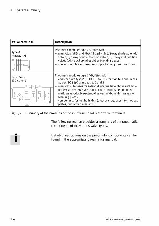
Valve terminal Description
Type 03
MIDI/MAXI
Pneumatic modules type 03, fitted with:
� manifolds (MIDI and MAXI) fitted with 5/2−way single−solenoid
valves, 5/2−way double−solenoid valves, 5/3−way mid−position
valves (with auxiliary pilot air) or blanking plates
� special modules for pressure supply, forming pressure zones
Type 04−B
ISO 5599−2
Pneumatic modules type 04−B, fitted with:
� adapter plate type VIGP−04−FB−8A−D−... for manifold sub−bases
as per ISO 5599−2 in sizes 1, 2 and 3
� manifold sub−bases for solenoid intermediate plates with hole
pattern as per ISO 5588−2, fitted with single−solenoid pneu�
matic valves, double−solenoid valves, mid−position valves or
blanking plates
� components for height linking (pressure regulator intermediate
plates, restrictor plates, etc.)
Fig.�1/2: Summary of the modules of the multifunctional Festo valve terminals
The following section provides a summary of the pneumatic
components of the various valve types.
Detailed instructions on the pneumatic components can be
found in the appropriate pneumatics manual.

1. System summary
1−5Festo P.BE−VIDN−03−8A−GB 0503a
1.2 Description of the components
The following connecting, display and operating elements
can be found on the pneumatic MIDI modules type 03:
1 2 3
4
5
1 Yellow LEDs (for each valve solenoid
coil)
2 Manual override (for each valve sole�
noid coil)
3 Valve location inscription field
(identification labels)
4 End plate with common tubing connec�
tions , for design variants see pneu�
matics manual
5 Work connections (2 per valve)
Fig.�1/3: Operating, display and connecting elements on the MIDI modules type 03
1. System summary
1−6 Festo P.BE−VIDN−03−8A−GB 0503a
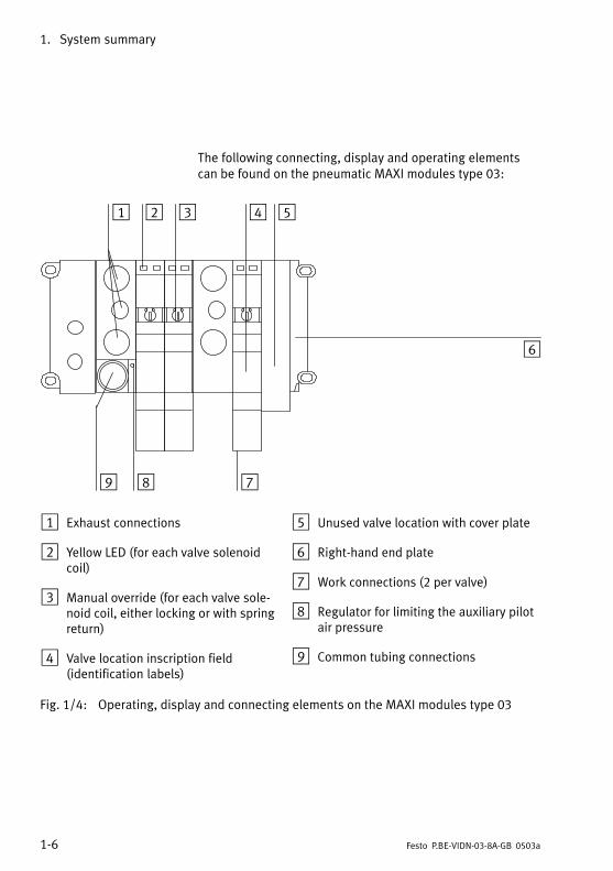
The following connecting, display and operating elements
can be found on the pneumatic MAXI modules type 03:
1 2 3 4 5
6
789
1 Exhaust connections
2 Yellow LED (for each valve solenoid
coil)
3 Manual override (for each valve sole�
noid coil, either locking or with spring
return)
4 Valve location inscription field
(identification labels)
5 Unused valve location with cover plate
6 Right−hand end plate
7 Work connections (2 per valve)
8 Regulator for limiting the auxiliary pilot
air pressure
9 Common tubing connections
Fig.�1/4: Operating, display and connecting elements on the MAXI modules type 03
1. System summary
1−7Festo P.BE−VIDN−03−8A−GB 0503a
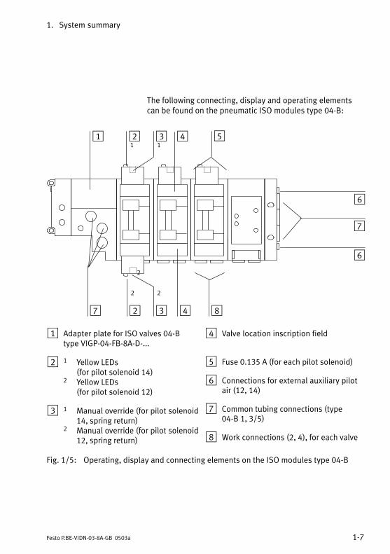
The following connecting, display and operating elements
can be found on the pneumatic ISO modules type 04−B:
11
2
22
1 2 3 4 5
6
8432
6
7
7
1 Adapter plate for ISO valves 04−B
type VIGP−04−FB−8A−D−...
2 1 Yellow LEDs
(for pilot solenoid 14)
2 Yellow LEDs
(for pilot solenoid 12)
3 1 Manual override (for pilot solenoid
14, spring return)
2 Manual override (for pilot solenoid
12, spring return)
4 Valve location inscription field
5 Fuse 0.135 A (for each pilot solenoid)
6 Connections for external auxiliary pilot
air (12, 14)
7 Common tubing connections (type
04−B 1, 3/5)
8 Work connections (2, 4), for each valve
Fig.�1/5: Operating, display and connecting elements on the ISO modules type 04−B

1. System summary
1−8 Festo P.BE−VIDN−03−8A−GB 0503a
Please note
For connecting ISO modules type 04−B special adapter
plates of type VIGP−04−FB−8A−D−... are required for the field
bus connection module.

1. System summary
1−9Festo P.BE−VIDN−03−8A−GB 0503a
1.3 Method of operation
1 Field bus connec�
tion module
2 Field bus branch
cable
3 Field bus main
cable
4 T−adapter
5 Compressed air
(1)
6 Work air (2, 4)
2
3
1
34 5
66
Fig.�1/6: Method of operation of a valve terminal
The field bus connection module performs the following:
� It connects the valve terminal to the appropriate field bus
and to the operating voltage.
� It carries out the system settings of the terminal. An auto�
matic valve test and further functions dependent on the
field bus can be set.
� It controls data transfer to/from the field−bus module on
your control system.
� It controls the internal functions of the valve terminal.

1. System summary
1−10 Festo P.BE−VIDN−03−8A−GB 0503a
The pneumatic modules provide the following:
� the common channels for the supply and exhaust air
� the electric signals from all the valve solenoid coils
Work connections 2 and 4 have been provided for each valve
location on the individual pneumatic modules.
The valves are supplied with compressed air via the common
channels on the pneumatic end plate or via special air supply
modules. The exhaust air and pilot exhaust are also vented
via these channels or special modules. Further modules are
also available for pressure supply in order, e.g. to permit
tasks with different working pressures or alternatively to
enable MIDI/MAXI valves or ISO valves to be mounted on a
node.
Further information on the use of these modules can be
found in the �Pneumatics manual� for your valve terminal.

Fitting
2−1Festo P.BE−VIDN−03−8A−GB 0503a
Chapter 2

2. Fitting
2−2 Festo P.BE−VIDN−03−8A−GB 0503a
Contents
2. Fitting 2−1. . . . . . . . . . . . . . . . . . . . . . . . . . . . . . . . . . . . . . . . . . . . . . . . . . . . . . . .
2.1 Fitting the modules and components 2−3. . . . . . . . . . . . . . . . . . . . . . . . . . . . . . .
2.1.1 Internal earthing of the end plate 2−4. . . . . . . . . . . . . . . . . . . . . . . . . . . . . . . . . .
2.1.2 Hat rail clamping unit (type 03) 2−6. . . . . . . . . . . . . . . . . . . . . . . . . . . . . . . . . . . .
2.2 Fitting the valve terminal onto a wall (types 03 and 04B) 2−7. . . . . . . . . . . . . . .
2.3 Fitting onto a hat rail (type 03) 2−9. . . . . . . . . . . . . . . . . . . . . . . . . . . . . . . . . . . .

2. Fitting
2−3Festo P.BE−VIDN−03−8A−GB 0503a
2.1 Fitting the modules and components
The valve terminal is supplied from the factory already fitted.
If you wish to supplement or exchange individual modules or
components, please refer to the following manuals:
� "Pneumatics manual" for fitting the pneumatic modules
� The fitting instructions supplied with the product in the
case of modules and components ordered at a later date.
Please note
Treat all modules and components of the valve terminal
with great care. Pay attention in particular to the follow�
ing:
S Screw connectors must not be distorted or subjected to
mechanical stress. Screws must fit exactly (otherwise
the threads will be damaged).
S The specified torques must be observed.
S Modules must not be offset (IP 65).
S Connecting surfaces must be clean (avoid leakage and
faulty contacts).
S The contacts of type 03 valve solenoid coils must not be
bent (they are not resistant to bending in both directions
and will break off if bent back).

2. Fitting
2−4 Festo P.BE−VIDN−03−8A−GB 0503a
2.1.1 Internal earthing of the end plate
You will require a right−hand end plate as a mechanical ter�
mination of the valve terminal. This end plate fulfils the fol�
lowing functions:
� it complies with protection class IP 65
� it contains an earth connection/contact
� it contains holes to enable it to be fitted onto a wall and,
in the case of type 03, also for the hat rail clamping unit.
The right−hand end plate of the ISO valve terminals is con�
nected conductively to the manifold sub−base by means of
screw connectors and pre−fitted spring contacts and is there�
fore sufficiently earthed.
There are various designs of the right−hand end plate for
valve terminal type 03 (MIDI/MAXI). Each design has a pre−
fitted earth cable.
Please note
Before fitting together valve terminal type 03, earth the
right−hand end plate with the earth cable. You will then
avoid interference caused by electromagnetic influences.

2. Fitting
2−5Festo P.BE−VIDN−03−8A−GB 0503a
Earth the end plate as follows:
1. Right−hand end plate (type 03):
In order to earth the right−hand end plate, connect the
pre−fitted cable on the inside to the appropriate contacts
on the pneumatic modules (see following diagram).
Please note
Instructions on earthing the complete valve terminal can
be found in the Chapter "Installation." The diagram below
shows how the end plate is fitted, using the example of a
valve terminal type 03.
1 Pre−fitted earth
cable
2 Fastening screws
max. 1 Nm
3 Seal
4 Contact for earth
cable
2
34
1
Fig.�2/1: Fitting the end plate (example terminal type 03)

2. Fitting
2−6 Festo P.BE−VIDN−03−8A−GB 0503a
2.1.2 Hat rail clamping unit (type 03)
If you wish to fit the valve terminal onto a hat rail (support
rail as per EN 50022), you will require the hat rail clamping
unit. The hat rail clamping unit should be fastened onto the
rear of the end plate and the field bus connection module as
shown in the following diagram.
Please observe the following:
Before fitting
� The surfaces to which the rubber feet are to be glued
must be clean (clean with spirit).
� The flat−head screws must be tightened (item 3).
After fitting
� Secure the lever by means of a retaining screw (item 7).
1 Left−hand lever *)
2 O−ring
3 Flat−head screw
4 Right−hand
lever *)
5 Rubber foot self−
adhesive
6 Clamping el�
ements
7 Retaining screw
1
2 3
4
5
6
7
Fig.�2/2: Fitting the hat rail clamping unit

2. Fitting
2−7Festo P.BE−VIDN−03−8A−GB 0503a
2.2 Fitting the valve terminal onto a wall (types 03 and 04B)
Proceed as follows:
1. Ascertain the weight of your valve terminal (by weighing
or calculating). Guide values:
Valve terminal module
Type 03 *)
� per pneumatic module (incl. valves)
MIDI
0.8 kg
MAXI
1.2 kg
Type 04−B manifold sub−bases*)
� adapter plate and right−hand end
plate
� per pneumatic module (incl. mani�
fold sub−base, solenoid intermediate
plate and valve)
ISO size 1
3.0 kg
1.2 kg
ISO size 2
3.2 kg
1.6 kg
ISO size 3
4.1 kg
2.4 kg
Field bus connection module 0.5 kg 0.5 kg 0.5 kg
*) Components for height linking: Weight see pneumatics manual
2. Make sure that the mounting surface can support this
weight.
3. If necessary, use washers.
4. Fasten the terminal, depending on the type, according to
the table below. The terminal can be fitted in any desired
position.

2. Fitting
2−8 Festo P.BE−VIDN−03−8A−GB 0503a
Type of valve terminal Fastening possibilities
Type 03� With four M6 screws on the left−hand side of
the housing and the right−hand end plate
Type 04−B� With two M6 screws on the left−hand side of
the housing
� With three M6 screws (ISO sizes 1 and 2) or
M8 (ISO size 3) on the adapter plate and on
the right−hand end plate.
If necessary, use the following additional fasten�
ing possibilities:
� fastening screw per manifold sub−base
� the hole underneath the manifold sub−base
("Blind hole", see pneumatics manual)
2. Fitting
2−9Festo P.BE−VIDN−03−8A−GB 0503a
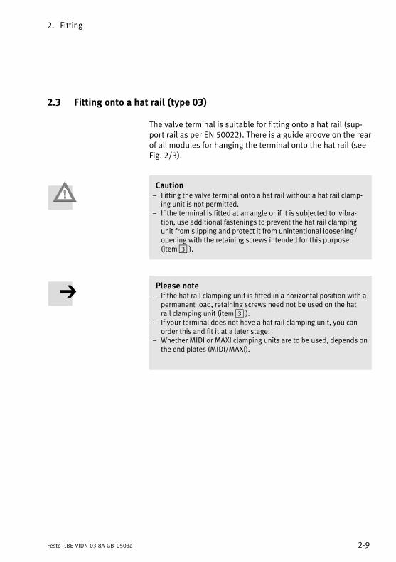
2.3 Fitting onto a hat rail (type 03)
The valve terminal is suitable for fitting onto a hat rail (sup�
port rail as per EN 50022). There is a guide groove on the rear
of all modules for hanging the terminal onto the hat rail (see
Fig. 2/3).
Caution
� Fitting the valve terminal onto a hat rail without a hat rail clamp�
ing unit is not permitted.
� If the terminal is fitted at an angle or if it is subjected to vibra�
tion, use additional fastenings to prevent the hat rail clamping
unit from slipping and protect it from unintentional loosening/
opening with the retaining screws intended for this purpose
(item�3�).
Please note
� If the hat rail clamping unit is fitted in a horizontal position with a
permanent load, retaining screws need not be used on the hat
rail clamping unit (item 3�).� If your terminal does not have a hat rail clamping unit, you can
order this and fit it at a later stage.
� Whether MIDI or MAXI clamping units are to be used, depends on
the end plates (MIDI/MAXI).

2. Fitting
2−10 Festo P.BE−VIDN−03−8A−GB 0503a
Proceed as follows:
1. Ascertain the weight of your terminal in accordance with
Chapter 2.2.
2. Make sure that the mounting surface can support this
weight.
3. Fit a hat rail (support rail as per EN 50022 − 35x15; width
35 mm, height 15 mm).
4. Fasten the hat rail to the mounting surface at least every
100 mm.
5. Hang the terminal onto the hat rail. Fasten the terminal
on both sides against tilting or slipping with the hat rail
clamping unit (see following diagram).
6. If the load vibrates or if the hat rail clamping unit is fitted
at an angle, protect it against unintentional loosening/
opening with the aid of two retaining screws (item 3).
1 Hat rail clamping
unit
2 Hat rail clamping
unit locked
3 Retaining screw
1 2 3 3
Fig.�2/3: Fitting valve terminal type 03 onto a hat rail
Installation
3−1Festo P.BE−VIDN−03−8A−GB 0503a
Chapter 3
3. Installation
3−2 Festo P.BE−VIDN−03−8A−GB 0503a
Contents
3. Installation 3−1. . . . . . . . . . . . . . . . . . . . . . . . . . . . . . . . . . . . . . . . . . . . . . . . . . .
3.1 General installation instructions 3−3. . . . . . . . . . . . . . . . . . . . . . . . . . . . . . . . . . .
3.2 Setting the node address and the field bus baud rate 3−5. . . . . . . . . . . . . . . . . .
3.3 Connecting the valve terminal 3−9. . . . . . . . . . . . . . . . . . . . . . . . . . . . . . . . . . . . .
3.3.1 Connecting cable 3−9. . . . . . . . . . . . . . . . . . . . . . . . . . . . . . . . . . . . . . . . . . . . . . .
3.3.2 Preparing the connecting cable 3−10. . . . . . . . . . . . . . . . . . . . . . . . . . . . . . . . . . . .
3.4 Selecting the power unit 3−12. . . . . . . . . . . . . . . . . . . . . . . . . . . . . . . . . . . . . . . . .
3.4.1 Ascertaining the current consumption 3−14. . . . . . . . . . . . . . . . . . . . . . . . . . . . . .
3.4.2 Connecting the load voltage for the valves 3−15. . . . . . . . . . . . . . . . . . . . . . . . . . .
3.5 Connecting the field bus 3−19. . . . . . . . . . . . . . . . . . . . . . . . . . . . . . . . . . . . . . . . .
3.5.1 Fitting a terminating resistor 3−24. . . . . . . . . . . . . . . . . . . . . . . . . . . . . . . . . . . . . .
3. Installation
3−3Festo P.BE−VIDN−03−8A−GB 0503a
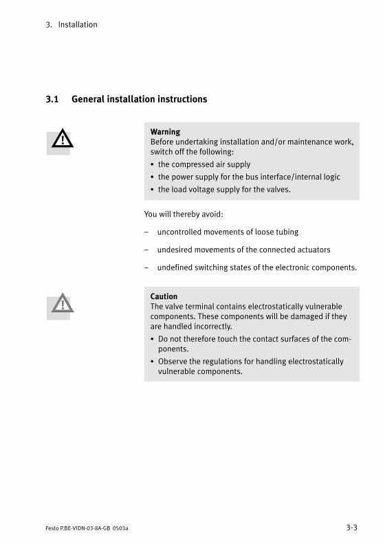
3.1 General installation instructions
Warning
Before undertaking installation and/or maintenance work,
switch off the following:
S the compressed air supply
S the power supply for the bus interface/internal logic
S the load voltage supply for the valves.
You will thereby avoid:
� uncontrolled movements of loose tubing
� undesired movements of the connected actuators
� undefined switching states of the electronic components.
Caution
The valve terminal contains electrostatically vulnerable
components. These components will be damaged if they
are handled incorrectly.
S Do not therefore touch the contact surfaces of the com�
ponents.
S Observe the regulations for handling electrostatically
vulnerable components.
3. Installation
3−4 Festo P.BE−VIDN−03−8A−GB 0503a
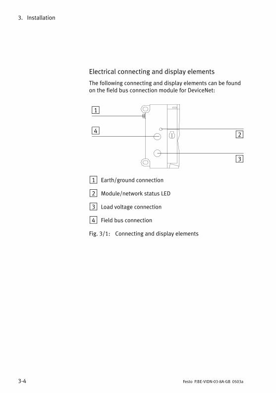
Electrical connecting and display elements
The following connecting and display elements can be found
on the field bus connection module for DeviceNet:
1
2
3
4
1 Earth/ground connection
2 Module/network status LED
3 Load voltage connection
4 Field bus connection
Fig.�3/1: Connecting and display elements

3. Installation
3−5Festo P.BE−VIDN−03−8A−GB 0503a
3.2 Setting the node address and the field bus baud rate
The following switches can be found under the cover of the
field bus connection module:
� DIL switches for setting the field bus baud rate
� address selector switches for selecting the node address
Open the cover as follows:
S If necessary, disconnect the field bus and operating volt�
age cables.
S Unscrew and remove both Philips screws in the cover.
S Carefully lift up the cover and remove it.
Close the cover as follows:
S Carefully place the cover in position.
S Carefully tighten the Philips screws in the cover.
1
2
1 Address selector switch (node address)
2 DIL switch for baud rate
Fig.�3/2: Setting elements under the cover of the housing

3. Installation
3−6 Festo P.BE−VIDN−03−8A−GB 0503a
Setting the node address
You can set the node address of the valve terminal with the
two address selector switches.The switches are numbered
from 0 to 9. The small arrow on the address selector switches
indicates the units or tens figure of the node address set.
1
2
1 Address selector switch for the UNITS figure
2 Address selector switch for the TENS figure
Fig.�3/3: Address selector switch
Node addresses may only be assigned once for each module/
scanner. We recommend that you assign the node addresses
in ascending order. If necessary, adapt the node addresses to
suit the machine structure of your system.

3. Installation
3−7Festo P.BE−VIDN−03−8A−GB 0503a
The following node addresses are permitted: 0...63
Proceed as follows:
1. Switch off the power supply for the bus interface/internal
logic as well as the load voltage supply for the valves.
2. Assign an unused node address to the valve terminal.
3. Use a screwdriver to set the arrow of the relevant address
selector switch to the units or tens figure of the desired
node address.
1 2
3
4
1 Setting for field bus address 05
2 Setting for field bus address 43
3 Address selector switch for TENS figure
4 Address selector switch for UNITS figure
Fig.�3/4: Examples of address settings
3. Installation
3−8 Festo P.BE−VIDN−03−8A−GB 0503a
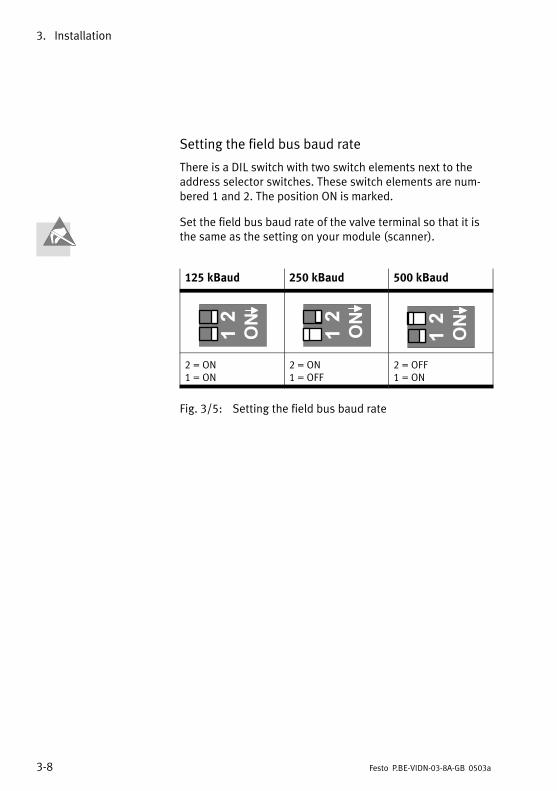
Setting the field bus baud rate
There is a DIL switch with two switch elements next to the
address selector switches. These switch elements are num�
bered 1 and 2. The position ON is marked.
Set the field bus baud rate of the valve terminal so that it is
the same as the setting on your module (scanner).
125 kBaud 250 kBaud 500 kBaud
2 = ON
1 = ON
2 = ON
1 = OFF
2 = OFF
1 = ON
Fig.�3/5: Setting the field bus baud rate

3. Installation
3−9Festo P.BE−VIDN−03−8A−GB 0503a
3.3 Connecting the valve terminal
3.3.1 Connecting cable
Use a twisted screened 4−core cable for the field bus. The bus
interface and the internal logic of the valve terminal are sup�
plied with power via the field bus cable.
Please note
S You must refer to the PLC manual or to the manual for
your scanner in order to ascertain the correct type of
cable to use.
S Take into account here the distance and the baud rate
selected. Select the appropriate cable diameter.
Notice the voltage drop:
� in the supply cable for the bus interface and
� in the internal logic of the valve terminal.
Bus length The table below shows the guide values for the distance de�
pending on the baud rate selected. Detailed information can
be found in the manuals for your control system and
scanner.
Baud rate Maximum
main bus
length
Branch line
length
(maximum)
Branch line
length
(cumulative)
125 kBaud 500 m 6 m 156 m
250 kBaud 250 m 78 m
500 kBaud 100 m 39 m

3. Installation
3−10 Festo P.BE−VIDN−03−8A−GB 0503a
Load voltage cable
S Use a load voltage cable of sufficient diameter.
S Avoid long distances between the power unit and the
valve terminal. If the load voltage cable is too long, the
voltage supplied by the power unit will be reduced.
S If necessary, ascertain the most suitable cable diameter
and the maximum permitted cable length.
3.3.2 Preparing the connecting cable
The connections of the field bus interface and of the load
voltage connection have been designed as plugs. The pin
assignments of the field bus interface and of the load voltage
connection can be found on the following pages.
Load voltage connection Use plugs from the Festo range for connecting the load
voltage. The plugs must fit the outer diameter of the cable
used (see Appendix A, Accessories).
Field bus plug Cables already fitted with plugs are available from various
manufacturers for connecting the field bus (see Appendix A,
Accessories).

3. Installation
3−11Festo P.BE−VIDN−03−8A−GB 0503a
Self−prepared plugs When you have selected suitable cables connect them as
follows:
1. Loosen the knurled centre nut to open the socket.
1 Cable
2 Strain relief
3 Connecting part
4 Housing
12
3
4
Fig.�3/6: Preparing the connecting cable
2. Open the strain relief at the rear of the housing. Then
pass the cable through the strain relief and the plug
housing.
3. Remove 5 mm of the insulation from the conductor and fit
end sleeves onto the wires.
4. Connect the ends of the conductors.
5. Replace the connecting part on the housing of the socket.
Pull the cable back so that it is not looped inside the
housing.
6. Tighten the strain relief.
3. Installation
3−12 Festo P.BE−VIDN−03−8A−GB 0503a
3.4 Selecting the power unit
Warning
S Use only PELV circuits as per IEC/DIN EN 60204−1 (Pro�
tective Extra−Low Voltage, PELV) for the electrical supply.
Consider also the general requirements for PELV circuits
in accordance with IEC/DIN EN 60204−1.
S Use power supplies which guarantee reliable electrical
isolation of the operating voltage as per IEC/DIN EN
60204−1.
By the use of PELV circuits, protection against electric shock
(protection against direct and indirect contact) is guaranteed
in accordance with IEC/EN 60204−1 (Electrical equipment for
machines, General requirements).

3. Installation
3−13Festo P.BE−VIDN−03−8A−GB 0503a
Before connecting the load voltage supply, please observe
the following:
S Avoid long distances between the power unit and the
valve terminal.
S The following applies as orientation values for your valve
terminal:
Cross−sectional area of
cable
Distance
1.5 mm2
2.5 mm2
� 8 m� 14 m
*) at Vo = 24 V
S If necessary, ascertain the complete current consumption
in accordance with the following table and then select a
suitable power unit as well as cables with a suitable
cross−sectional area.

3. Installation
3−14 Festo P.BE−VIDN−03−8A−GB 0503a
3.4.1 Ascertaining the current consumption
The table below shows you how to calculate the complete
current consumption for the terminal. The values quoted
have been rounded up. If you use other valves or modules,
please refer to the relevant technical specifications for their
current consumption.
Current consumption of bus interface and logic
Field bus connection module + 0.200�A
Current consumption of load voltage supply
Current consumption of all simultaneously energized valve coils
Type 03: MIDI: ____ x 0.055 A
MAXI ____ x 0.095 A
Type 04−B ISO with MUH 5.5 W: ____ x 0.230 A
ISO with MUH 3.1 W: ____ x 0.140 A
+ Σ � A
Total current consumption= Σ A
Fig.�3/7: Calculating the total current consumption

3. Installation
3−15Festo P.BE−VIDN−03−8A−GB 0503a
3.4.2 Connecting the load voltage for the valves
Caution
The load voltage supply for the valves (pin 2) must be pro�
tected with an external fuse with maximum 6 A. With the
aid of this external fuse you can avoid functional damage
to the valve terminal in the event of a short circuit.
The following components on the valve terminal are supplied
separately with +24 V DC via the load voltage connection:
� the valves (pin 2: +24 V DC, tolerance ±10 %, external
fuse max. 6 A required).
1
2
1 Earth connection
2 Load voltage supply
Fig.�3/8: Load voltage connection

3. Installation
3−16 Festo P.BE−VIDN−03−8A−GB 0503a
Please note
Check within the framework of your EMERGENCY STOP
circuit, to see which measures are necessary on your sys�
tem in order that it can be brought into a safe state in the
event of an EMERGENCY STOP (e.g. switching off the load
voltage for the valves and outputs, switching off the pres�
sure).
Recommendation:
Connect the load voltage for the valves (pin 2) via EMERG�
ENCY STOP.
S Check the 24 V operating voltage for the outputs while
your system is operating. Make sure that the operating
voltage of the outputs always lies within the permitted
tolerance, even during full−load operation.
Pin assignment of the load voltage connection
1 Not connected
2 24 V DC load volt�
age for valves
3 0 V load voltage
for valves
4 Earth connection
1
2
3
4
Fig.�3/9: Load voltage connection on the field bus connection module

3. Installation
3−17Festo P.BE−VIDN−03−8A−GB 0503a
Potential equalization
The valve terminal has two earth connections for potential
equalization:
� the load voltage connection (pin 4)
� the left−hand side of the housing (M4 thread)
Please note
S Always connect the earth potential to pin 4 of the load
voltage connection.
S Connect the earth connection of the left−hand side of the
housing to the earth potential with low impedance
(short cable with large cross−sectional area).
S By means of low−impedance connections, make sure
that the housing of the valve terminal and the earth con�
nection at pin 4 have the same potential and that there
are no equalizing currents.
You will thereby avoid faults due to electromagnetic in�
fluences and fulfil electromagnetic compatibility in com�
pliance with EMC guideline 89/336/EWG.
Connection examples
Please observe the following when connecting the load volt�
age supply:
S Fuse the load voltage supply for the valves externally with
maximum 6 A against short circuit/overload.
S Observe the tolerance of 24 V DC ± 10 %.
S Connect both earth connections for potential equaliz�
ation. Select here suitable cross−sectional areas for the
cables in order to prevent equalizing currents.

3. Installation
3−18 Festo P.BE−VIDN−03−8A−GB 0503a
24 V
0 V
DC
24 V
AC
230 V
1
2
3
45
3
1 Earth connection on the side of the
housing
2 Earth connection pin 4 designed for
12�A
3 Potential equalization
4 Load voltage can be switched off sep�
arately
5 External 6 A fuse
Fig.�3/10: Example of connection for load voltage supply

3. Installation
3−19Festo P.BE−VIDN−03−8A−GB 0503a
3.5 Connecting the field bus
There is a bus plug on the valve terminal for connection to
the DeviceNet. The following must be connected to this plug:
� the two bus cables
� the power supply (+ 24 V DC and 0 V) for the bus interface
and internal logic
� the cable screening
The hardware basis of the bus interface is the CAN bus. It is
typical for this bus that the bus interface is supplied with
voltage via the field bus plug.
The bus is connected by means of a branch line with a 5−pin
M12 socket with PG 9 screw connector. You can order this
from Festo (type: FBSD−GD−9−5POL). Alternately, you can use
ready−made bus cables from various manufacturers (see also
Appendix A, Accessories).
Please refer to your PLC manual or the scanner manual for
information on which T−adapter to use and on the maximum
length of branch line permitted with your controller.
The drawing below shows the layout of the bus interface and
the connection via a branch line.

3. Installation
3−20 Festo P.BE−VIDN−03−8A−GB 0503a
1
2 3 4 5
6
7
8
1 Field bus
2 Power supply
3 Screening
4 T−adapter
5 Branch line
6 Bus
7 Valve driver
8 Microprocessor
Fig.�3/11: Layout and connection of the bus interface

3. Installation
3−21Festo P.BE−VIDN−03−8A−GB 0503a
Bus/logic supply Avoid long distances between the bus interface/logic sup�
ply and the valve terminal.
Please note
The bus slaves of different manufacturers have different
tolerances in respect of the interface supply. Take this into
account when planning the bus length and the positioning
of the power unit.
Recommendation: Place the power unit approximately in the
centre of the bus. The following tolerance of the bus interface
supply applies to Festo valve terminals:
Vmax = 30.0 V
Vmin = 11.5 V
Pin assignment of field
bus interface
Connect the field bus cable correctly to the terminals of the
bus cable socket. Observe here also the further connecting
instructions in this manual as well as the instructions in the
manual for your controller or scanner.
Caution
Observe the correct polarity when connecting the field bus
interface and the power supply for the bus interface/inter�
nal logic. Also connect the screening.
3. Installation
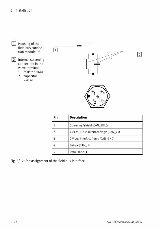
3−22 Festo P.BE−VIDN−03−8A−GB 0503a
1 Housing of the
field bus connec�
tion module PE
2 Internal screening
connection in the
valve terminal
1 resistor 1M�
2 capacitor
220 nF
1
2
12
Pin Description
1 Screening/shield (CAN_SHLD)
2 + 24 V DC bus interface/logic (CAN_V+)
3 0 V bus interface/logic (CAN_GND)
4 Data + (CAN_H)
5 Data − (CAN_L)
Fig.�3/12: Pin assignment of the field bus interface

3. Installation
3−23Festo P.BE−VIDN−03−8A−GB 0503a
Connecting instructions for DeviceNet
Please note
You must check the pin assignment of your scanner in the
relevant documentation.
Connect the field bus cable of your control system to the field
bus interface of the valve terminal as follows: The diagram
below shows the connections for the SLC scanner and for the
SF 60 valve terminals (integrated SLC scanner).
SLC scanner Valve terminal with field bus connection
module for DeviceNet
SLC scanner from Allen−Bradley
Red
White
Bare
Blue
Black
Pin 2 + 24 V Bus
Pin 4 Data+
Pin 1 Screening/shield
Pin 5 Data−
Pin 3 GND Bus
SF 60 from Festo with integrated SLC scanner
Pin 2 + 24 V Bus
Pin 4 Data+
Pin 1 Screening/shield
Pin 5 Data−
Pin 3 GND Bus
Pin 2 + 24 V Bus
Pin 4 Data+
Pin 1 Screening/shield
Pin 5 Data−
Pin 3 GND Bus
Fig.�3/13: Connections for DeviceNet

3. Installation
3−24 Festo P.BE−VIDN−03−8A−GB 0503a
3.5.1 Fitting a terminating resistor
If the valve terminal to be connected is at the end of the field
bus, you must fit a terminating resistor (120 Ohm, 0.25 Watt).
If you are using a T−adapter, we recommend that the termin�
ating resistor be fitted at the unused output of the T−adapter.
If you are not using a T−Adapter, you must fit the terminating
resistor in the field bus socket. To do this, crimp the wires of
the resistor together with those of the field bus cable be�
tween the cores Data + (pin 4) and Data − (pin 5) on the bus
cable socket.
Please note
S Squeeze the wires of the resistor and those of the bus
cable together in common core end sleeves in order to
guarantee good electrical contact.
1
1 Terminating resistor 120 Ohm, 0.25 W
Fig.�3/14: Terminating resistor in the socket for the field bus
cable

Commissioning
4−1Festo P.BE−VIDN−03−8A−GB 0503a
Chapter 4

4. Commissioning
4−2 Festo P.BE−VIDN−03−8A−GB 0503a
Contents
4. Commissioning 4−1. . . . . . . . . . . . . . . . . . . . . . . . . . . . . . . . . . . . . . . . . . . . . . . .
4.1 Preparing the valve terminal for commissioning 4−3. . . . . . . . . . . . . . . . . . . . . .
4.1.1 Compiling the configuration list 4−3. . . . . . . . . . . . . . . . . . . . . . . . . . . . . . . . . . .
4.1.2 Address assignment of the valve terminal 4−4. . . . . . . . . . . . . . . . . . . . . . . . . . .
4.1.3 Address assignment after extension/conversion 4−7. . . . . . . . . . . . . . . . . . . . . .
4.1.4 Switching on the power supply 4−9. . . . . . . . . . . . . . . . . . . . . . . . . . . . . . . . . . . .
4.2 Commissioning on the DeviceNet 4−10. . . . . . . . . . . . . . . . . . . . . . . . . . . . . . . . . .
4.2.1 Configuring DeviceNet slave characteristics (EDS) 4−11. . . . . . . . . . . . . . . . . . . .
4.2.2 General information on parametrizing 4−13. . . . . . . . . . . . . . . . . . . . . . . . . . . . . .
4.2.3 Instructions on parametrizing with RSNetWorx for DeviceNet 4−14. . . . . . . . . . .

4. Commissioning
4−3Festo P.BE−VIDN−03−8A−GB 0503a
4.1 Preparing the valve terminal for commissioning
Please note
Supply the valve terminal separately with load voltage.
The field bus interface of the valve terminal is supplied
with voltage via the field bus cable.
4.1.1 Compiling the configuration list
Before commissioning or programming you must compile a
configuration list of all the connected field bus slaves.
On the basis of this list you can:
� carry out a comparison between the NOMINAL and
ACTUAL configurations, in order to detect any connection
faults.
� refer to these specifications during the syntax check of a
program, in order to avoid addressing faults.

4. Commissioning
4−4 Festo P.BE−VIDN−03−8A−GB 0503a
4.1.2 Address assignment of the valve terminal
The valve terminal with direct connection for DeviceNet al�
ways occupies 8 output and 8 input addresses, irrespective
of the number of valve solenoid coils fitted on the valve ter�
minal. The current switching status of the outputs is shown
by the input data. If the load voltage available is too low, an
active output will be represented as inactive in the input
data. Further information can be found in Appendix A.
The table below specifies the number of output addresses
assigned per manifold. 2 valves can be fitted onto MIDI/MAXI
manifolds; 1 valve can be fitted onto ISO manifolds.
Type Valve manifold Number of
outputs
Type 03 MIDI/MAXI manifold
� single solenoid manifold
� double solenoid manifold
2 outputs
4 outputs
Type 04−B ISO manifold
� single solenoid manifold
� double solenoid manifold
1 outputs
2 outputs
Fig.�4/1: Number of assigned outputs per manifold

4. Commissioning
4−5Festo P.BE−VIDN−03−8A−GB 0503a
Basic addressing rules
� The valve terminal with direct connection for DeviceNet
always occupies 8 output and 8 input addresses. Maxi�
mum 8 valve solenoid coils can be addressed. The
switching status of the valve solenoid outputs is shown
above the input addresses (8 bits). Providing there is a
sufficient load voltage supply, an activated valve coil out�
put will always be shown as switched (status 1).
� The addresses are assigned in ascending order without
gaps. Counting begins on the field bus connection mod�
ule from left to right.
� If two addresses are assigned for one valve location, the
following assignment applies:
pilot solenoid 14 occupies the lower−value address,
pilot solenoid 12 occupies the higher−value address.
� If single solenoid valves are fitted onto double solenoid
manifolds, the relevant addresses for valve solenoid coils
(4 or 2 outputs) will nevertheless be assigned. The
higher−value address in each case will then remain un�
used. If unused valve locations are fitted with blanking
plates, the addresses will still be assigned.
Pressure supply modules and intermediate pressure supply
modules do not occupy any addresses.

4. Commissioning
4−6 Festo P.BE−VIDN−03−8A−GB 0503a
The diagram below shows as an example the addressing se�
quence of the individual valve solenoid coils of a valve ter�
minal of type 03. Bit 6 and bit 7 are not used in this example
and are reserved for later extensions.
6,7
1 2
30 1 23 5 4
1 Single solenoid manifold
2 Double solenoid manifold
3 Sequence of address assignment (bit 0
to bit 7, bit 6 and bit 7 reserved)
Fig.�4/2: Address assignment of a valve terminal (example type 03)

4. Commissioning
4−7Festo P.BE−VIDN−03−8A−GB 0503a
4.1.3 Address assignment after extension/conversion
A special feature of the multifunctional valve terminal is its
flexibility. If the demands placed on the machine change, the
equipment fitted on the valve terminal can also be changed.
Caution
If extensions or conversions to the valve terminal are made
at a later stage, the input/output addresses may be
shifted. This applies in the following cases:
� When one or several pneumatic modules are added or
removed at a later stage (type 03/04−B).
� When a pneumatic module with single solenoid valves is
replaced by a new module with double solenoid valves
or vice versa (type 03/04−B).

4. Commissioning
4−8 Festo P.BE−VIDN−03−8A−GB 0503a
The diagram below shows, as an example, the address as�
signment when the valve terminal in the previous diagram is
extended with a single solenoid manifold with 2 single sole�
noid valves.
1 1 2
360 1 2 3 5 4 7
4
1 Single solenoid manifold
2 Double solenoid manifold
3 Sequence of address assignment (bit 0
to bit 7)
4 Extension with single solenoid mani�
fold (example)
Fig.�4/3: Address assignment of a valve terminal after extension/conversion

4. Commissioning
4−9Festo P.BE−VIDN−03−8A−GB 0503a
4.1.4 Switching on the power supply
Please note
Observe here also the instructions in the manual for your
controller.
When you switch your controller on, it will automatically carry
out a comparison between the NOMINAL and ACTUAL con�
figurations. It is important for this configuration comparison
that:
� the specifications on the configuration are complete and
correct.
� the field bus slaves are supplied with power in order that
they can be recognized when the ACTUAL configuration is
ascertained.
Therefore, switch on the power supply for all the field bus
slaves simultaneously, e.g. via a central switch, or switch the
power supply on in the following sequence:
1. First switch on the power supply for all the field bus
slaves.
2. Secondly, switch on the power supply for the control
system.

4. Commissioning
4−10 Festo P.BE−VIDN−03−8A−GB 0503a
4.2 Commissioning on the DeviceNet
General If the valve terminal is used on the DeviceNet, the following
special features must be observed:
� The addresses of all recognized DeviceNet slaves can be
assigned freely to the PLC operands in the Scan List
(input/output file).
� The address of a network slave is assigned in ascending
order. Addresses may only be assigned once.
� The input and output addresses can be assigned inde�
pendently of each other.
Please note
Assign the addresses of the network slaves so that there is
sufficient reserve available for later extensions.
The following sections contain general instructions on confi�
guring a valve terminal on the DeviceNet.
Detailed information can be found in the documentation of
the helps of the configuration program you are using.

4. Commissioning
4−11Festo P.BE−VIDN−03−8A−GB 0503a
4.2.1 Configuring DeviceNet slave characteristics (EDS)
When you commission a new DeviceNet slave the first time,
you must inform your configuration program of certain char�
acteristics of the slave. The characteristics of the various
slaves are managed by the configuration program mostly in a
list or library, e.g EDS library (EDS = electronic data sheets).
You can extend the EDS library in one of the following ways:
� by installing an EDS file
� by entering the slave characteristics manually.
Installing an EDS file
A CD−ROM is supplied with this manual for extending the EDS
library. On this CD−ROM you will find an EDS file and a picture
file (icon and bitmap) for the valve terminal.
File type File name
EDS file VIDN−03.EDS
ICO file (icon) VIDN−03.ICO
BMP file (bitmap) VIDN−03.BMP
Instructions on the directory structure of the CD−ROM can be
found in the file README.TXT in the main directory of the
CD−ROM.

4. Commissioning
4−12 Festo P.BE−VIDN−03−8A−GB 0503a
EDS file The EDS file contains all the necessary characteristics of
valve terminal type VIDN−03−8A. You can install this file with
the help of your configuration program.
ICO/BMP file Depending on the configuration program used, you can as�
sign the bitmap file or the icon file to the valve terminal. The
valve terminal will then be represented in the configuration
program accordingly.
Instructions on installing an EDS file and an ICO or BMP file
can be found in the manual or in the helps for your configur�
ation program.
Entering the slave characteristics manually
When an EDS file is installed, the following information about
the DeviceNet slave is added to the EDS library.
Information Description
Vendor Name Festo Corporation (26 D)
Device Type Pneumatic valve (27 D)
Product Code 4587
Major Revision/Minor Revision 2.1
Input size / Output size 1 Byte / 1 Byte
Product Name VIDN−03−8A
Catalog Number Typ 03 Valve terminal small
When the EDS library has been extended, the valve terminal
is entered in the slave list as a possible DeviceNet slave. It
can now be added to a network.

4. Commissioning
4−13Festo P.BE−VIDN−03−8A−GB 0503a
4.2.2 General information on parametrizing
When you have configured the slave characteristics (e.g. by
installing the EDS file), you will require the following steps for
parametrizing, depending on the configuration program:
1. Add slave to project/network (online or offline). If the
slave is added offline, it will be selected from the slave
list and added to the network
2. Assign the slave to a scanner. A network can contain sev�
eral scanners. The slaves must be assigned to a scanner.
3. Determine the I/O parameters of the slave. The following
must be specified:
S Number of I/O bytes to be transmitted. For valve ter�
minal type VIDN−03−8A: 1 byte for receive data and 1
byte for send data.
S The communication type. For valve terminal type
VIDN−03−8A: Polled or Change of State; strobed data
cannot be used.
S Assign the I/O addresses of the slave to the PLC oper�
ands.
4. Load the configuration into the scanner.

4. Commissioning
4−14 Festo P.BE−VIDN−03−8A−GB 0503a
4.2.3 Instructions on parametrizing with RSNetWorx for DeviceNet
This section tells you how to parametrize with RSNetWorx for
DeviceNet version 2.11.51 from Rockwell.
Adding the slave to the project/network
RSNetWorx for DeviceNet contains an EDS assistant which
you can use for installing the EDS file. When the EDS file has
been installed, the valve terminal is entered in the �Hard�
ware� list. You can transfer slaves to the network on the
right−hand side by dragging them across with the mouse.
1
1 Valve terminal type VIDN−03−8A in the �Hardware� list.
Fig.�4/4: Hardware list and network in the RSNetWorx for DeviceNet
4. Commissioning
4−15Festo P.BE−VIDN−03−8A−GB 0503a
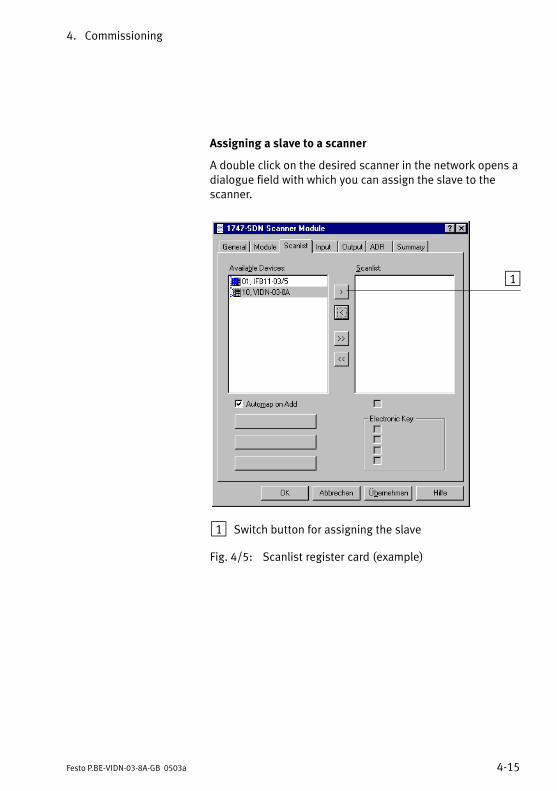
Assigning a slave to a scanner
A double click on the desired scanner in the network opens a
dialogue field with which you can assign the slave to the
scanner.
1
1 Switch button for assigning the slave
Fig.�4/5: Scanlist register card (example)
4. Commissioning
4−16 Festo P.BE−VIDN−03−8A−GB 0503a
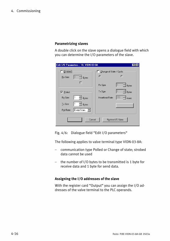
Parametrizing slaves
A double click on the slave opens a dialogue field with which
you can determine the I/O parameters of the slave.
Fig.�4/6: Dialogue field �Edit I/O parameters�
The following applies to valve terminal type VIDN−03−8A:
� communication type Polled or Change of state; strobed
data cannot be used
� the number of I/O bytes to be transmitted is 1 byte for
receive data and 1 byte for send data.
Assigning the I/O addresses of the slave
With the register card �Output� you can assign the I/O ad�
dresses of the valve terminal to the PLC operands.
4. Commissioning
4−17Festo P.BE−VIDN−03−8A−GB 0503a
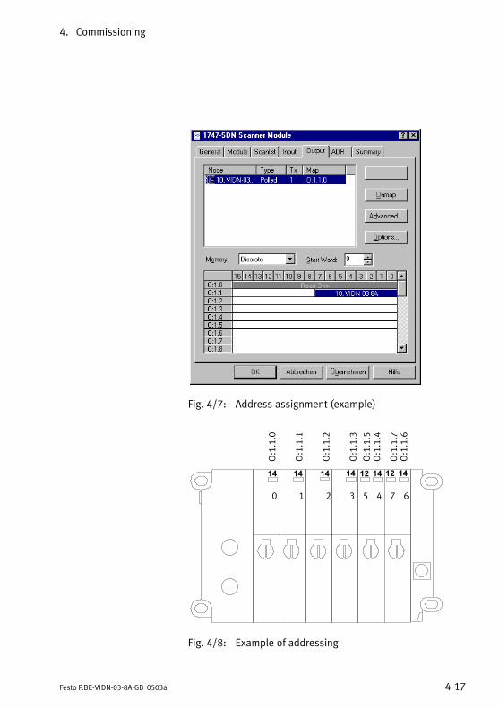
Fig.�4/7: Address assignment (example)
60 1 2 3 5 4 7
O:1.1.0
O:1.1.1
O:1.1.2
O:1.1.3
O:1.1.4
O:1.1.5
O:1.1.6
O:1.1.7
Fig.�4/8: Example of addressing

4. Commissioning
4−18 Festo P.BE−VIDN−03−8A−GB 0503a
Loading the configuration into the scanner
Finally, load the configuration data into the scanner. Further
information on this can be found in the documentation for
your scanner.
Diagnosis and error treatment
5−1Festo P.BE−VIDN−03−8A−GB 0503a
Chapter 5

5. Diagnosis and error treatment
5−2 Festo P.BE−VIDN−03−8A−GB 0503a
Contents
5. Diagnosis and error treatment 5−1. . . . . . . . . . . . . . . . . . . . . . . . . . . . . . . . . . .
5.1 Summary of diagnostic possibilities 5−3. . . . . . . . . . . . . . . . . . . . . . . . . . . . . . . .
5.1.1 Diagnosis by means of LEDs 5−4. . . . . . . . . . . . . . . . . . . . . . . . . . . . . . . . . . . . . .
5.1.2 Normal operating status 5−5. . . . . . . . . . . . . . . . . . . . . . . . . . . . . . . . . . . . . . . . .
5.1.3 Error display of the module/network status LED 5−5. . . . . . . . . . . . . . . . . . . . . .
5.1.4 LED for status display of the valve solenoid coils 5−7. . . . . . . . . . . . . . . . . . . . . .
5.1.5 Testing the valves 5−9. . . . . . . . . . . . . . . . . . . . . . . . . . . . . . . . . . . . . . . . . . . . . . .
5.1.6 Reaction to faults in the control system 5−12. . . . . . . . . . . . . . . . . . . . . . . . . . . . .
5.1.7 Diagnosis on the Allen−Bradley DeviceNet 5−13. . . . . . . . . . . . . . . . . . . . . . . . . . .

5. Diagnosis and error treatment
5−3Festo P.BE−VIDN−03−8A−GB 0503a
5.1 Summary of diagnostic possibilities
The valve terminal offers the following possibilities for diag�
nosis and error treatment:
� Diagnosis by means of the integrated LEDs
� valve terminal status
� valve status display
� Diagnosis by means of the valve test
� Diagnosis by means of the field bus
Diagnosis by means of
module/network status
LED
The combination LED for module/network status is a two−
coloured LED. This lights up or flashes either green or red,
or green and red simultaneously (orange) depending on the
operating status of the valve terminal. It indicates the status
of the module and the network.
Diagnosis by means of sig�
nal status display
There is a yellow LED for each valve solenoid coil. This
indicates whether or not the relevant valve solenoid coil is
energized.
Diagnosis by means of
valve test
This integrated test routine enables the valves to switch
automatically and cyclically.
Diagnosis by means of
field bus
You can evaluate the Device Failure Table via the user pro�
gram.

5. Diagnosis and error treatment
5−4 Festo P.BE−VIDN−03−8A−GB 0503a
5.1.1 Diagnosis by means of LEDs
Module/network status
LED
The LED on the field bus connection module indicates the
operating status of the valve terminal.
1 Module/network
status LED
1
Fig.�5/1: Module/network status LED
LED test When the communication module is switched on, the follow�
ing LED test is carried out:
� LED lights up green for 250 ms
� LED lights up red for 250 ms.

5. Diagnosis and error treatment
5−5Festo P.BE−VIDN−03−8A−GB 0503a
5.1.2 Normal operating status
In normal operating status the LED for the module/network
status lights up green.
Reaction Colour Operating status Error treatment
Green Normal; the valve terminal is
online and is connected to a
communication partner
None
5.1.3 Error display of the module/network status LED
Reaction Colour Operating status Error treatment
None � The bus interface of the valve
terminal is not supplied with
power.
� The valve terminal does not
recognize any communica�
tion on the bus.
S Check power supply to bus
interface/internal logic
S Check set baud rate
S Check physical connection to
bus and terminating resistor
Flashes green The valve terminal is ready for
data exchange and is online on
the bus. However, there is no
communication with a partner
(master). Possibly the valve ter�
minal is not yet assigned to
a master.
S Complete configuration.
Check/correct scan list of ap�
propriate master.
Flashes red,
fast
Non−permitted station number
is set.
S Set a station number be�
tween 0...63.
Flashes red,
slowly
Fault can be rectified
� Valve terminal has recog�
nized communication time−
out.
� Valve terminal has not been
addressed for a long period
(time−out time).
S Physical bus connection is
interrupted. Check master
for communication ability
S Reset time−out status of
valve terminal by reallocat�
ing. Reconnect valve terminal
to the bus.

5. Diagnosis and error treatment
5−6 Festo P.BE−VIDN−03−8A−GB 0503a
Reaction Error treatmentOperating statusColour
Lights up red Serious communication fault
� The valve terminal has dis�
covered too many incorrect
telegrams on the bus and no
longer participates in bus
communication. The valve
terminal is in bus−off status
or
� the station number of the
valve terminal has been as�
signed twice.
S Bad physical bus connection;
check connection.
S Bus has many faults; rectify
faults, check screening.
S Power supply to bus is inter�
rupted.
S Data cables of one slave con�
nected with incorrect polar�
ity; rectify.
S Check/correct baud rate.
S Correct station number.
Lights up
orange
Load voltage for valves is too
low.
S Correct undervoltage at load
voltage connection.
LED flashes
alternately
red/green
Valve test is active (see section
5.1.5)
None

5. Diagnosis and error treatment
5−7Festo P.BE−VIDN−03−8A−GB 0503a
5.1.4 LED for status display of the valve solenoid coils
MIDI/MAXI valves
There is a yellow LED for each valve solenoid coil. This LED
indicates the switching status of the valve solenoid coil.
1
1 Yellow LED per pilot solenoid (12, 14)
LED Switch position of valve solenoid
coil
Meaning
Yellow out Basic position Logical 0 (no signal)
Yellow alight � switch position
or
� basic position
Logical 1 (signal present)
Logical 1 but:
� operating voltage of outputs lies
below permitted tolerance range
(21.6 V...26.4 V DC) or
� compressed air supply not correct or
� pilot exhaust blocked or
� servicing required
Fig.�5/2: LEDs on the bus node

5. Diagnosis and error treatment
5−8 Festo P.BE−VIDN−03−8A−GB 0503a
ISO valves type 04−B
The valve solenoid coils of valve terminal type 04−B are pro�
tected with special fuses against short circuit and overload.
The method of replacing these fuses is described in the pneu�
matics manual for your valve terminal.
1
2
2 Yellow LED for pilot solenoid 14
3 Yellow LED for pilot solenoid 12
LED Switching status of valve solenoid
coil
Meaning
Yellow OUT � Basic position Logical 0 (no signal)
Yellow ON � basic position
or
� switch position
Logical 1 (signal present)
Logical 1, but:
� operating voltage of outputs lies
below permitted tolerance range
(21.6 V...26.4 V DC) or
� compressed air supply not correct or
� controller blocked or
� return for repairs
Fig.�5/3: LED display of switching status of ISO valve solenoid coil type 04 B

5. Diagnosis and error treatment
5−9Festo P.BE−VIDN−03−8A−GB 0503a
5.1.5 Testing the valves
Warning
Sudden unexpected movements of the actuators can
cause considerable damage. Before starting the test there�
fore, switch off the compressed air supply to the valves
Caution
� This test function runs automatically within the valve
terminal. All valves are switched on/off cyclically.
� None of the programmed interlockings or conditions for
further switching will be taken into consideraton.
The valve terminal provides the following test routines:
Test routine Meaning
Parallel All valves are switched on and off simulta�
neously at 1 second intervals.
Serial All valves are switched on and off individ�
ually one after the other at 1 second inter�
vals.
This test routine is repeated until the power supply to the
valve terminal is switched off.

5. Diagnosis and error treatment
5−10 Festo P.BE−VIDN−03−8A−GB 0503a
Starting the test routine
1. Switch off the compressed air supply for all the valves.
2. Switch off the load voltage supply for the bus interface
and the internal logic as well as the load voltage for the
valves.
3. Open the field bus connection module as described in
Chapter 2, "Opening and closing the node."
4. Note the posititons of the address selector switches and
the DIL switch elements.
5. Set address 99 and set DIL switches 1 and 2 to OFF.
6. Switch on the power supples for the bus interface and the
internal logic as well as the load voltage for the valves.
7. Set the desired test routine on the address selector
switches as follows:
Test routine Address to be set
Parallel 0
Serial 1
8. To start set DIL switches 1 and 2 to ON.
If faults occur at the start of the test routine, the LED will
flash red fast. The procedure must then be repeated.
During the test routine the module/network status LED
flashes alternately red/green.

5. Diagnosis and error treatment
5−11Festo P.BE−VIDN−03−8A−GB 0503a
Stopping the test routine
1. Switch off the power supplies for the bus interface and
the internal logic.
2. Set the address selector switch and DIL switch elements
1 and 2 to their original positions.

5. Diagnosis and error treatment
5−12 Festo P.BE−VIDN−03−8A−GB 0503a
5.1.6 Reaction to faults in the control system
Reaction to PLC stop Reaction to field bus faults Reaction to field bus inter�
ruption
Valves are reset. Valves are reset when time out
has expired.
Valves are reset immediately.
Please note
If all the outputs are reset after a PLC stop, a field bus in�
terruption or a field bus fault, you must observe the fol�
lowing "pneumatic rules:"
� Unilaterally−actuated valves move to the basic position.
� Double−solenoid valves remain in their current position.
� Mid−position valves move to the mid−position (depend�
ing on the type of valve either pressurized, exhausted or
blocked).

5. Diagnosis and error treatment
5−13Festo P.BE−VIDN−03−8A−GB 0503a
5.1.7 Diagnosis on the Allen−Bradley DeviceNet
The following bus diagnoses can be used:
� diagnosis by means of the DeviceNet scanner
� diagnosis by means of the user program.
Diagnosis by means of the DeviceNet scanner
The valve terminal with field bus connection module for the
DeviceNet reacts on the DeviceNet as regards diagnosis like
equivalent DeviceNet slaves. Special error messages are not
displayed.
Diagnosis by means of the user program
You can evaluate the Device Failure table by means of the
user program. The Device Failure table is divided into several
sections. The section "Communications failure bitmap" is
interesting in conjunction with the valve terminal. In this sec�
tion, an error bit is set for each DeviceNet slave if communi�
cation between the scanner and the slaves is interrupted or is
faulty.
The error bit is set for the valve terminal if:
� the bus connection is interrupted (e.g. plug discon�
nected) or
� if the bus interface is not supplied with power.

5. Diagnosis and error treatment
5−14 Festo P.BE−VIDN−03−8A−GB 0503a

Technical Appendix
A−1Festo P.BE−VIDN−03−8A−GB 0503a
Appendix A

A. Technical Appendix
A−2 Festo P.BE−VIDN−03−8A−GB 0503a
Contents
A. Technical Appendix A−1. . . . . . . . . . . . . . . . . . . . . . . . . . . . . . . . . . . . . . . . . . . . .
A.1 Accessories A−3. . . . . . . . . . . . . . . . . . . . . . . . . . . . . . . . . . . . . . . . . . . . . . . . . . . .
A.2 DeviceNet specifications for the valve terminal A−7. . . . . . . . . . . . . . . . . . . . . . .
A.2.1 Identity object: class code 01 (0x01) A−11. . . . . . . . . . . . . . . . . . . . . . . . . . . . . . .
A.2.2 Router object: class code 02 (0x02) A−13. . . . . . . . . . . . . . . . . . . . . . . . . . . . . . . .
A.2.3 DeviceNet object: class code 03 (0x03) A−13. . . . . . . . . . . . . . . . . . . . . . . . . . . . .
A.2.4 Assembly object: class code 04 (0x04) A−15. . . . . . . . . . . . . . . . . . . . . . . . . . . . . .
A.2.5 Connection object: class code 05 (0x05) A−17. . . . . . . . . . . . . . . . . . . . . . . . . . . .
A.3 Technical specifications A−26. . . . . . . . . . . . . . . . . . . . . . . . . . . . . . . . . . . . . . . . . .
A.4 Index A−30. . . . . . . . . . . . . . . . . . . . . . . . . . . . . . . . . . . . . . . . . . . . . . . . . . . . . . . . .

A. Technical Appendix
A−3Festo P.BE−VIDN−03−8A−GB 0503a
A.1 Accessories
This section provides a summary of all necessary acces�
sories.
The following summaries make no claim to be complete. The
addresses of the firms mentioned can be found at the end of
the section.
Valve supply connection
Power is supplied to the valves via a 4−pin M12 socket with a
PG 7 or PG 9 screw connector. You can order these from
Festo.
Design Type Part no.
PG 7 straight
PG 9 straight
PG 7 angled
PG 9 angled
FBSD−GD7
FBSD−GD9
FBSD−WD7
FBSD−WD9
18497
18495
18524
18525
Bus connection
The bus can be connected via a branch line with a 5−pin M12
socket with a PG 9 screw connector. You can order these from
Festo.
Design Type Part no.
PG 9 straight FBSD−GD9−5POL 18324

A. Technical Appendix
A−4 Festo P.BE−VIDN−03−8A−GB 0503a
Alternately, you can use ready−made bus cables (drop cable,
M12 / 7/8") from the following manufacturers:
Manufacturer Type Length
Lumberg RS50 RKT5−614/1.5F
RS50 RKT5−614/3F
RS50 RKT5−614/6F
RS50 RKT5−614/9F
1.5 F
3.0 F
6.0 F
9.0 F
Turck RSM 572−*M−RKC
4.5T/S630
x m
*) Length in metres
The branch line can be connected to the bus via a T−adapter
(T−tap). The following T−taps are offered to suit the bus cables
named:
Manufacturer Type
Lumberg TAP 50−RK
Turck RSM−2RKM 57
Woodhead DN 3000
T−adapters with screw terminals are offered by the following
manufacturers:
Manufacturer Type
Phillips BR50
Selectron CTA 701

A. Technical Appendix
A−5Festo P.BE−VIDN−03−8A−GB 0503a
Addresses
Manufacturer Address(es)
Woodhead Industries Inc. United States
Daniel Woodhead Company
3411 Woodhead Drive
Northbrook, Illinois 60062
Canada
Woodhead Canada Ltd.
1090 Brevik Place
Mississauga, Ontario
Canada L4W 3Y5
United Kingdom
Aero−Motive (U.K.) Ltd.
9, Rassau Industrial Estate
Ebbw Vale, Gwent
NP3 5SD
Germany
H. F. Vogel GmbH
Tullastraße 9
75196 Remchingen
Lumberg United States
Lumberg Inc.
11351 Business Center Drive
USA−Richmond,VA 23236
United Kingdom
Lumberg (U.K.) Ltd.
The Mount, Highclere
Newbury, Berkshire,
RG 20 9QZ
Germany
Lumberg GmbH & Co.
Hälverstraße 94
D−58579 Schalksmühle

A. Technical Appendix
A−6 Festo P.BE−VIDN−03−8A−GB 0503a
Manufacturer Address(es)
Turck United States
Turck Inc.
3000 Campus Drive
USA−Plymouth,
MN 55441−2656
United Kingdom
MTE Turck Ltd.
Stephenson Road
Leigh−on−Sea,
Essex SS9 5LS
Deutschland
Hans Turck Gmbh & Co. KG
Witzlebenstraße 7
D−45472 Mülheim an der Ruhr
Philips Niederlande
PMA Nederland
Gebouw TQIII−4
Postbus 80025
NL−5600 JZ Eindhoven
Deutschland
Philips Industrial Electronics
Miramstraße 87
D−34123 Kassel
Selectron Schweiz
Selectron Lyss AG
Industrielle Elektronik
Bernstrasse 70
CH−3250 Lyss
Deutschland
Selectron System GmbH
Schupfer Straße 1
Postfach 31 02 62
D−90202 Nürnberg

A. Technical Appendix
A−7Festo P.BE−VIDN−03−8A−GB 0503a
A.2 DeviceNet specifications for the valve terminal
DeviceNet Release 2.0
The valve terminal with field bus connection module type
IDN−03−8A is operated like a slave on the DeviceNet network.
As a DeviceNet slave, the valve terminal operates according
to the Predefined master/slave connection set as Group 2
server and supports the following in the master/slave con�
nection:
� explicit messages
� polled I/O messages
� COS cyclic messages.
"Explicit Unconnected Message Manager" (UCMM) cannot be
used with this valve terminal.

A. Technical Appendix
A−8 Festo P.BE−VIDN−03−8A−GB 0503a
Discrete�Input
Message�Router
I/O
DeviceNet
Identity
Connection
Class
Physical�Link
Explicit
Msg.
Discrete�Output
VALVE�MANIFOLD
0 1 20 1 2
I/O�Assembly
Solenoid�ChannelsGeneral�Purpose
Discrete�Inputs
Fig.�A/4:: Overview
DeviceNet Object Classes
The following DeviceNet object classes can be used:
Object type Class code # of Instances
Identity 0x01 1
Router 0x02 1
DeviceNet 0x03 1
Assembly 0x04 2 (1 for OUTPUT, 1 for INPUT)
Connection 0x05 3 (explicit, polled I/O, COS
cyclic)

A. Technical Appendix
A−9Festo P.BE−VIDN−03−8A−GB 0503a
Object type # of InstancesClass code
Solenoid status 0x08 1
Discrete out�
puts
0x09 1
The objects for this device affect its behavior in the following
manner:
Object classes Effect on behavior
Identity Supports the reset service
Message Router No affect
DeviceNet Configures port attributes
Assembly Defines I/O data format
Connection Contains the number of logical ports
Discrete input Defines the behavior of solenoid status
and discrete input points
Solenoid output Defines the behavior of solenoid output
points

A. Technical Appendix
A−10 Festo P.BE−VIDN−03−8A−GB 0503a
Defining object interfaces
The objects in this device have the following listed interfaces:
Object Classes Interface/s
Identity Message router
Message router Explicit Messaging Connection Instance
DeviceNet Message router
Assembly Message router or I/O connection
Connection Message router
Discrete input Message router or assembly object
Discrete output Message router or assembly object

A. Technical Appendix
A−11Festo P.BE−VIDN−03−8A−GB 0503a
A.2.1 Identity object: class code 01 (0x01)
The identity object provides information for identifying the
device as well as general information on the device.
Attribute Access Name Type Value
1 Get Revision UINT 1
1 Get Max. Instance UINT 2
Identity Object, Instance 1 Attributes
Attribute Access Name Type Value
1 Get Vendor UINT 0x1A
2 Get Product type UINT 0x1B
3 Get Product code UINT 0x11EB
4 Get Revision STRUCT OF
Major revision UINT 2
Minor revision UINT 1
5 Get Device status UINT (see under 1�)
6 Get Serial number UINT (see under 2�)
7 Get Product name STRUCT OF
Length UINT 10
Name STRING [6] VIDN−03−8A
8 Get State UINT Not supported
9 Get Configuration Con�
sistency Value
UINT Not supported
10 Get/Set Heartbeat Interval UINT

A. Technical Appendix
A−12 Festo P.BE−VIDN−03−8A−GB 0503a
Common services
Service code Class Instance Service name
05 (0x05) No Yes Reset
14 (0x0E) Yes Yes Get_Attribute_Single
1 Slave status
bit 0 owned 0=not owned
1=owned (allocated)
bit 1 reserved 0
bit 2 configured 0
bit 3 reserved 0
bit 4−7 vendor specific 0
bit 8 minor cfg fault 0=no fault
1=minor fault
bit 9 minor dev.fault 0=no fault
1=minor device fault
bit 10 major cfg.fault 0=no fault
1=major cfg. fault
bit 11 major dev.fault 0=no fault
1=major device fault
bit 12−15 reserved 0
Hinweis
Only bits 0 and 9 are used.
2 Unique serial number

A. Technical Appendix
A−13Festo P.BE−VIDN−03−8A−GB 0503a
A.2.2 Router object: class code 02 (0x02)
The message router object represents a message connection
by means of which a service to any object class or instance in
the physical device can be addressed.
A.2.3 DeviceNet object: class code 03 (0x03)
Class Attributes
Attribute Access Name Type Value
1 Get Revision UINT 2
Instance 1 attributes
Attribute Access Name Type Value
1 Get MACID UINT Rotary switch
2 Get Baud rate UINT DIP switch: 0=125,
1=250, 2=500
3 Get/Set Bus off interrupt BOOL (see under 3�)
4 Get/Set Bus off counter UINT 0x00
(see under 4�)
5 Get/Set Allocation information STRUCT OF Allocate service (see
under 5�)
Choice byte BYTE
Master node addr. UINT

A. Technical Appendix
A−14 Festo P.BE−VIDN−03−8A−GB 0503a
Common services
Service code Class Instance Service name
14 (0x0E) Yes Yes Get_Attribute_Single
16 (0x10) No Yes Set_Attribute_Single
75 (0x4B) No Yes Allocate master/slave
76 (0x4C) No Yes Release master/slave
3 Bus off interrupt (BOI) will be triggered if the bus off state
occurs. The following values are used:
Bus off interrupt (BOI) Action
0 Hold chip in OFF state (default)
1 If possible reset CAN chip
4 If the bus off counter is reset, it will become 0, irrespective
of the data value supplied.
5 Allocation_byte
7 6 5 4 3 2 1 0
Reserve Ack.
Surpress
Cyclic Change of
state
Reserve Bit strobe Polled Explicit
message
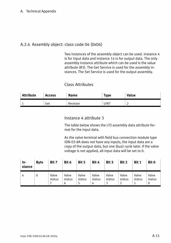
A. Technical Appendix
A−15Festo P.BE−VIDN−03−8A−GB 0503a
A.2.4 Assembly object: class code 04 (0x04)
Two instances of the assembly object can be used. Instance 4
is for input data and instance 14 is for output data. The only
assembly instance attribute which can be used is the value
attribute (#3). The Get Service is used for the assembly in�
stances. The Set Service is used for the output assembly.
Class Attributes
Attribute Access Name Type Value
1 Get Revision UINT 2
Instance 4 attribute 3
The table below shows the I/O assembly data attribute for�
mat for the input data.
As the valve terminal with field bus connection module type
IDN−03−8A does not have any inputs, the input data are a
copy of the output data, but one (bus) cycle later. If the valve
voltage is not applied, all input data will be set to 0.
In�
stance
Byte Bit 7 Bit 6 Bit 5 Bit 4 Bit 3 Bit 2 Bit 1 Bit 0
4 0 Valve
status
7
Valve
status
6
Valve
status
5
Valve
status
4
Valve
status
3
Valve
status
2
Valve
status
1
Valve
status
0

A. Technical Appendix
A−16 Festo P.BE−VIDN−03−8A−GB 0503a
Instance 34 attribute 3
The table below shows the I/O assembly data attribute for�
mat for the output data which contain several pneumatic out�
puts.
In�
stance
Byte Bit 7 Bit 6 Bit 5 Bit 4 Bit 3 Bit 2 Bit 1 Bit 0
34 0 Pneum.
output
7
Pneum.
output
6
Pneum.
output
5
Pneum.
output
4
Pneum.
output
3
Pneum.
output
2
Pneum.
output
1
Pneum.
output
0
Common Services
Service Code Class Instance Service Name
14 (0x0E) Yes Yes Get_Attribute_Single
16 (0x10) Yes Yes Set_Attribute_Single

A. Technical Appendix
A−17Festo P.BE−VIDN−03−8A−GB 0503a
A.2.5 Connection object: class code 05 (0x05)
The connection objects manage the features of each com�
munication connection. As a slave of group II, the valve
terminal supports:
� one explicit message connection
� a polled I/O message connection
� COS cyclic message connection.
There are three instances of the connection object in the de�
vice. Instance #1 is assigned to the explicit message connec�
tion. Instance #2 is assigned to the poll I/O connection. In�
stance #4 is assigned to the COS cyclic I/O connection.
Connection object class attributes
Attribute Access Name Type Value
1 Get Revision UINT 1

A. Technical Appendix
A−18 Festo P.BE−VIDN−03−8A−GB 0503a
Connection object, instance 1 attribute
(Explicit Message)
Attribute Access Name Type Value
1 Get State UINT (see under 1�)
2 Get Instance type UINT 0 = Explicit message
3 Get Transport class trigger UINT 0x83
4 Get Production connection
ID
UINT (see under 2�)
5 Get Consumed connection
ID
UINT (see under 2�)
6 Get Initial comm. char. UINT 0x21
7 Get Production size UINT 07
8 Get Consumed size UINT 07
9 Get/Set Expected packet rate UINT Apllication dependent
12 Get/Set Timeout action UINT (see under 3�)
13 Get Prod. path length UINT 0
14 Get Production path (zero) (see under 4�)
15 Get Cons. path length UINT 0
16 Get Consumed path (zero) (see under 4�)
17 Get Production Inhibit UINT 0

A. Technical Appendix
A−19Festo P.BE−VIDN−03−8A−GB 0503a
Connection object, instance 2 attributes (POLL con�
nection)
Attribute Access Name Type Value
1 Get State UINT (see under 1�)
2 Get Instance type UINT 1 = I/O Message
3 Get Transport class trigger UINT 0x82
4 Get Production connection ID UINT (see under 2�)
5 Get Consumed connection ID UINT (see under 2�)
6 Get Initial comm. char. UINT 0x1
7 Get Production size UINT 1
8 Get Consumed size UINT 1
9 Get/Set Expected packet rate UINT
12 Get/Set Timeout action UINT (see under 3�)
13 Get Prod. path length UINT 6
14 Get Production path STRUCT OF
Log. Seg., class UINT 0x20
Class number UINT 0x04 (Assembly)
Log.Seg., instance UINT 0x24
Instance number UINT 0x04 (Solenoid status)
Log.Seg., attribute UINT 0x30
Attribute number UINT 0x03
15 Get Cons. path length UINT 6
16 Get Consumed path STRUCT OF
Log. Seg., class UINT 0x20
Class number UINT 0x04 (Assembly)
Log.Seg., instance UINT 0x24
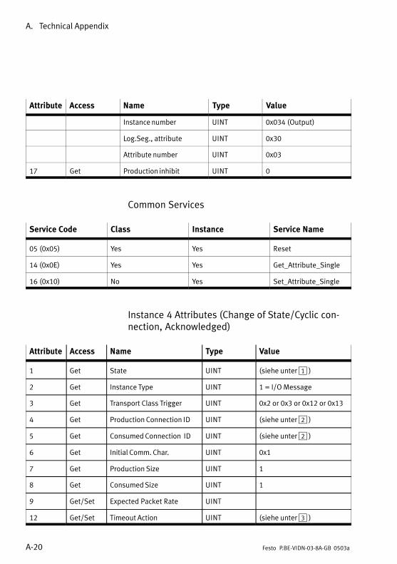
A. Technical Appendix
A−20 Festo P.BE−VIDN−03−8A−GB 0503a
Attribute ValueTypeNameAccess
Instance number UINT 0x034 (Output)
Log.Seg., attribute UINT 0x30
Attribute number UINT 0x03
17 Get Production inhibit UINT 0
Common Services
Service Code Class Instance Service Name
05 (0x05) Yes Yes Reset
14 (0x0E) Yes Yes Get_Attribute_Single
16 (0x10) No Yes Set_Attribute_Single
Instance 4 Attributes (Change of State/Cyclic con�
nection, Acknowledged)
Attribute Access Name Type Value
1 Get State UINT (siehe unter 1�)
2 Get Instance Type UINT 1 = I/O Message
3 Get Transport Class Trigger UINT 0x2 or 0x3 or 0x12 or 0x13
4 Get Production Connection ID UINT (siehe unter 2�)
5 Get Consumed Connection ID UINT (siehe unter 2�)
6 Get Initial Comm. Char. UINT 0x1
7 Get Production Size UINT 1
8 Get Consumed Size UINT 1
9 Get/Set Expected Packet Rate UINT
12 Get/Set Timeout Action UINT (siehe unter 3�)

A. Technical Appendix
A−21Festo P.BE−VIDN−03−8A−GB 0503a
Attribute ValueTypeNameAccess
13 Get Prod. Path Length UINT 6
14 Get Production Path STRUCT of
Log. Seg., Class UINT 0x20
Class Number UINT 0x04 (Assembly)
Log.Seg., Instance UINT 0x24
Instance Number UINT 0x04(Solenoid Status)
Log.Seg., Attribute UINT 0x30
Attribute Number UINT 0x03
15 Get Cons. Path Length UINT 6
16 Get Consumed Path STRUCT of
Log. Seg., Class UINT 0x20
Class Number UINT 0x2B (Ack. Handler)
Log.Seg., Instance UINT 0x24
Instance Number UINT 0x01
Log.Seg., Attribute UINT 0x30
Attribute Number UINT 0x03
17 Get Production Inhibit UINT 0

A. Technical Appendix
A−22 Festo P.BE−VIDN−03−8A−GB 0503a
Common Services
Service Code Class Instance Service Name
05 (0x05) Yes Yes Reset
14 (0x0E) Yes Yes Get_Attribute_Single
16 (0x10) No Yes Set_Attribute_Single
Instance 4 Attributes (Change of State/Cyclic con�
nection, Unacknowledged)
Attribute Access Name Type Value
1 Get State UINT (siehe unter 1�)
2 Get Instance Type UINT 1 = I/O Message
3 Get Transport Class Trigger UINT 0x0 or 0x10
4 Get Production Connection ID UINT (siehe unter 2�)
5 Get Consumed Connection ID UINT 0xFFFF
6 Get Initial Comm. Char. UINT 0xF
7 Get Production Size UINT 1
8 Get Consumed Size UINT 0
9 Get/Set Expected Packet Rate UINT
12 Get/Set Timeout Action UINT (siehe unter 3�)
13 Get Prod. Path Length UINT 6

A. Technical Appendix
A−23Festo P.BE−VIDN−03−8A−GB 0503a
Attribute ValueTypeNameAccess
14 Get Production Path STRUCT of
Log. Seg., Class UINT 0x20
Class Number UINT 0x04 (Assembly)
Log.Seg., Instance UINT 0x24
Instance Number UINT 0x04 (Solenoid Status)
Log.Seg., Attribute UINT 0x30
Attribute Number UINT 0x03
15 Get Cons. Path Length UINT 0
16 Get Consumed Path STRUCT of
Log. Seg., Class UINT
Class Number UINT
Log.Seg., Instance UINT
Instance Number UINT
Log.Seg., Attribute UINT
Attribute Number UINT
17 Get Production Inhibit UINT 0

A. Technical Appendix
A−24 Festo P.BE−VIDN−03−8A−GB 0503a
Common Services
Service Code Class Instance Service Name
05 (0x05) Yes Yes Reset
14 (0x0E) Yes Yes Get_Attribute_Single
16 (0x10) No Yes Set_Attribute_Single
1 Connection States:
0 = non−existent
1 = configuring
3 = established
4 = timed out
2 Connection ID’s:
Connection 1 Produced Connection ID: 10xxxxxx011
Connection 1 Consumed Connection ID: 10xxxxxx100
Connection 2 Produced Connection ID: 01111xxxxxx
Connection 2 Consumed Connection ID: 10xxxxxx101
xxxxxx = Node Address.
3 Watch Dog TimeOut Activity:
0 = Timeout (Explicit Messaging default)
1 = Auto Delete
2 = Auto Reset
4 If no data is available during the poll response a 0 length
(zero) packet is returned.

A. Technical Appendix
A−25Festo P.BE−VIDN−03−8A−GB 0503a
A.3 Technical specifications
General
Protection class (as per EN
60529)
Plug connector inserted or fitted
with protective cap
Temperature in
� operation
� storage/transport
IP 65
−�5 °C ... +50 °C−20 °C ... +60 °C
Vibration
(as per DIN/IEC68/EN 60068
part 2−6 and as per IEC 721/EN
60068 part 2−3)
� transport
� operation/use
Shock
(as per DIN/IEC 68/EN 60068
part 2−27 and IEC 721)
3.5 mm path at 2−8 Hz
1 g acceleration at 8−25 Hz
0.35 mm path at 25−57 Hz
5 g acceleration at 57−150 Hz
1 g acceleration at 150−200 Hz
30 g at 11 ms duration
Protection against electric
shock
(protection against direct and in�
direct contact as per IEC/DIN EN
60204−1)
by means of PELV circuits
(Protective�Extra−Low Voltage)
Elektromagnetic compatibility
� Interference emitted
� Immunity against interference
Tested as per DIN EN 61000−6−4
(industry)1)
Tested as per DIN EN 61000−6−2
(industry)
1) The component is intended for industrial use.
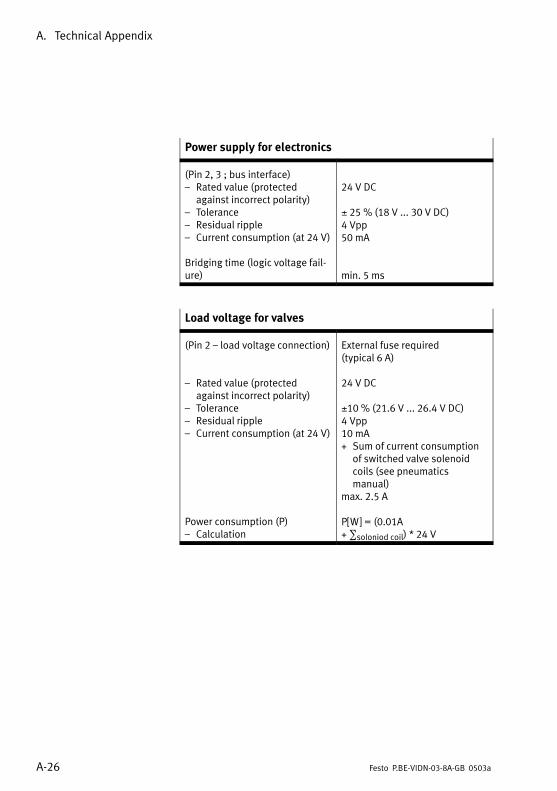
A. Technical Appendix
A−26 Festo P.BE−VIDN−03−8A−GB 0503a
Power supply for electronics
(Pin 2, 3 ; bus interface)
� Rated value (protected
against incorrect polarity)
� Tolerance
� Residual ripple
� Current consumption (at 24 V)
Bridging time (logic voltage fail�
ure)
24 V DC
± 25 % (18 V ... 30 V DC)
4 Vpp
50 mA
min. 5 ms
Load voltage for valves
(Pin 2 � load voltage connection)
� Rated value (protected
against incorrect polarity)
� Tolerance
� Residual ripple
� Current consumption (at 24 V)
Power consumption (P)
� Calculation
External fuse required
(typical 6 A)
24 V DC
±10 % (21.6 V ... 26.4 V DC)
4 Vpp
10 mA
+ Sum of current consumption
of switched valve solenoid
coils (see pneumatics
manual)
max. 2.5 A
P[W] = (0.01A
+ ∑soloniod coil) * 24 V

A. Technical Appendix
A−27Festo P.BE−VIDN−03−8A−GB 0503a
Field bus
Design ISO 11898
Transmission type Serial asynchronous, half−
duplex
Protocol Allen−Bradley DeviceNet
Baud rate 125...500 kBaud
Cable type
� depends on cable length and
field bus baud rate set
See controller manual
Technical specifications for the pneumatic components and
the valves can be found in the pneumatics manual.

A. Technical Appendix
A−28 Festo P.BE−VIDN−03−8A−GB 0503a
A. Technical Appendix
A−29Festo P.BE−VIDN−03−8A−GB 0503a
A.4 Index
A
Abbreviations IX. . . . . . . . . . . . . . . . . . . . . . . . . . . . . . . . . . . . .
Accessories A−3. . . . . . . . . . . . . . . . . . . . . . . . . . . . . . . . . . . . .
Address selector switch 3−6. . . . . . . . . . . . . . . . . . . . . . . . . . . .
Addressing 4−4, 4−5. . . . . . . . . . . . . . . . . . . . . . . . . . . . . . . . . .
C
Connecting cables 3−11. . . . . . . . . . . . . . . . . . . . . . . . . . . . . .
Connections
ISO modules 1−7. . . . . . . . . . . . . . . . . . . . . . . . . . . . . . . . . . .
MAXI modules 1−6. . . . . . . . . . . . . . . . . . . . . . . . . . . . . . . . .
MIDI modules 1−5, 1−6, 1−7. . . . . . . . . . . . . . . . . . . . . . . . . .
Current
calculation 3−14. . . . . . . . . . . . . . . . . . . . . . . . . . . . . . . . . .
fuses 3−16. . . . . . . . . . . . . . . . . . . . . . . . . . . . . . . . . . . . . . .
D
Designated use V. . . . . . . . . . . . . . . . . . . . . . . . . . . . . . . . . . .
E
Earthing
components 2−4, 2−5. . . . . . . . . . . . . . . . . . . . . . . . . . . . . . .
potential equalization 3−17. . . . . . . . . . . . . . . . . . . . . . . . .
EDS library 4−11. . . . . . . . . . . . . . . . . . . . . . . . . . . . . . . . . . . .
EMERGENCY STOP circuit 3−16. . . . . . . . . . . . . . . . . . . . . . . .
End plate 2−4, 2−5. . . . . . . . . . . . . . . . . . . . . . . . . . . . . . . . . . . .
F
Field bus baud rate 3−8. . . . . . . . . . . . . . . . . . . . . . . . . . . . . . .

A. Technical Appendix
A−30 Festo P.BE−VIDN−03−8A−GB 0503a
Field bus interface 3−22. . . . . . . . . . . . . . . . . . . . . . . . . . . . . .
Fuse, external 3−16. . . . . . . . . . . . . . . . . . . . . . . . . . . . . . . . . .
H
Hat rail 2−6, 2−9. . . . . . . . . . . . . . . . . . . . . . . . . . . . . . . . . . . . .
I
Important user instructions VII. . . . . . . . . . . . . . . . . . . . . . . . .
N
Node address 3−5. . . . . . . . . . . . . . . . . . . . . . . . . . . . . . . . . . . .
S
Service VI. . . . . . . . . . . . . . . . . . . . . . . . . . . . . . . . . . . . . . . . . .
Setting the node address 3−5. . . . . . . . . . . . . . . . . . . . . . . . . .
Switching status, valves 5−9. . . . . . . . . . . . . . . . . . . . . . . . . . .
T
Target group VI. . . . . . . . . . . . . . . . . . . . . . . . . . . . . . . . . . . . . .
Technical specifications A−20. . . . . . . . . . . . . . . . . . . . . . . . . .
Terminating resistor 3−24. . . . . . . . . . . . . . . . . . . . . . . . . . . . .
Test routine, valves 5−9. . . . . . . . . . . . . . . . . . . . . . . . . . . . . . .
V
Valves
ISO 1−7. . . . . . . . . . . . . . . . . . . . . . . . . . . . . . . . . . . . . . . . . . .
MAXI 1−4, 1−6. . . . . . . . . . . . . . . . . . . . . . . . . . . . . . . . . . . . .
MIDI 1−4, 1−5, 1−6, 1−7. . . . . . . . . . . . . . . . . . . . . . . . . . . . . .
Voltage, selected cables 3−12. . . . . . . . . . . . . . . . . . . . . . . . .