valve guide - nexcess cdn · opposite pump side (outlet) standard ... valve guide. body dimension...
TRANSCRIPT

ALIGN NOTCH ON TRUNNIONAS SHOWN
NOTE: POSITION SHOWN WITH BALL OPEN.POSITION D
INLET OUTLET
ALIGN NOTCH ON TRUNNIONAS SHOWN
NOTE: POSITION SHOWN WITH BALL OPEN.
INLET OUTLET
ALIGN NOTCH ON TRUNNIONAS SHOWN
NOTE: POSITION SHOWN WITH BALL OPEN.
INLET OUTLET
ALIGN NOTCH ON TRUNNIONAS SHOWN
INLET OUTLET
NOTE: POSITION SHOWN WITH BALL OPEN.
POSITION CPOSITION A
POSITION B
16:1
16:1
16:1
16:1
Electric Actuator Positions & Gear Actuator
N
C
J
Q
W
X
OPPOSITE PUMP SIDE (OUTLET)
STANDARD
PUMP SIDE (INLET)OPEN VALVETO REMOVE
OPEN VALVETO REMOVE
WITH THE VALVE CLOSED.ALL HANDLE POSITIONS SHOWN ARE
Handle Positions Clock Wise To Open
V
K
M
H
G
P
OPPOSITE PUMP SIDE (OUTLET)PUMP SIDE (INLET)OPEN VALVETO REMOVE
OPEN VALVETO REMOVE
WITH THE VALVE CLOSED.ALL HANDLE POSITIONS SHOWN ARE
Handle Positions Counter Clock Wise To Open
To place an order, state the style number, inlet and outlet adapters needed (always list inlet adapter first), and the type of handle/actuator. All threaded adapters require thread information. Rigid female adapters are available only with tapered pipe thread (NPT). Hose threaded adapters will be supplied with National Hose (NH) thread unless otherwise specified.
Style Description Ball Type Actuators
8620 2" Generation II Heavy Duty Non-Locking Swing-Out Valve Stainless Steel SZ, R/S, EA or GA8625 2 1/2" Generation II Heavy Duty Non-Locking Swing-Out Valve Stainless Steel SZ, R/S, EA or GA8630 3" Generation II Heavy Duty Non-Locking Swing-Out Valve Stainless Steel SZ, R/S, EA or GA8635 3 1/2" Generation II Heavy Duty Non-Locking Swing-Out Valve Stainless Steel SZ, R/S, EA or GA
8810 1" Heavy Duty “Self Locking" Swing-Out Valve Stainless Steel R1, TS, TSC8815 1 1/2" Heavy Duty “Self Locking" Swing-Out Valve Stainless Steel R1, TS, TSC8820 2" Generation II Heavy Duty “Self Locking" Swing-Out Valve Stainless Steel R1, SZ, TS, or TSC8825 2 1/2" Generation II Heavy Duty “Self Locking" Swing-Out Valve Stainless Steel R1, SZ, TS, or TSC8830 3" Generation II Heavy Duty “Self Locking" Swing-Out Valve Stainless Steel R1, SZ, TS, or TSC8835 3 1/2" Generation II Heavy Duty “Self Locking" Swing-Out Valve Stainless Steel R1, SZ, TS, or TSC8840 4" Heavy Duty “Self Locking" Swing-Out Valve Bronze, Flat Air, EA or GA
8910 1" Heavy Duty “Self Locking" Swing-Out Valve Fusion CF R1, TS, TSC8915 1 1/2" Heavy Duty Swing-Out Valve Fusion CF R1, TS, TSC8920 2" Generation II Heavy Duty Swing-Out Valve Fusion CF R1, TS, TSC, SZ, R/S, EA or GA 8925 2 1/2" Generation II Heavy Duty Swing-Out Valve Fusion CF R1, TS, TSC, SZ, R/S, EA or GA 8930 3" Generation II Heavy Duty Swing-Out Valve Fusion CF R1, TS, TSC, SZ, R/S, EA or GA 8935 3 1/2" Generation II Heavy Duty Swing-Out Valve Fusion CF R1, TS, TSC, SZ, R/S, EA or GA 8940 4" Heavy Duty Swing-Out Valve Fusion CF Air, EA or GA
Valve BodySelect style number from chart
Inlet Adapter Select from adapter list
Outlet Adapter Select from adapter list
Enter “CH" to specify chrome option where available. Refer to adapter list for availability. Leave Blank for Standard Cast Finish
Specify Actuator Select from actuator chart above
Specify Actuator Position See chart at right for positions. “N" is standard for manual actuators
Optional Slo-Cloz™ Enter “SC" to specify or leave blank for no Slo-Cloz
P1-S8925 ME1-S CH TS N
Example shown is a 2 1/2" valve with composite ball. It has a P1-S inlet adapter and a ME1-S outlet adapter, with chrome plating. The valve has a TS handle in standard position “N" and does not have Slo-Cloz installed.* For special configurations, contact Akron Brass customer service
Actuator/Handle
Inlet/Pump Side Adapte (See Adapter List)
Body Outlet Adapter (See Adapter List)
Optional: Defaults Are Shown
Actuator/Handle Type
Options Order Code
R1 R1TS TS
TSC TSCSZ SZ
Gear Actuator GA
Electric Actuator EARack & Sector RS
AK
RO
N B
RA
SS
CO
MP
AN
Y | P
H. 8
00
.22
8.116
1 (33
0.2
64
.56
78
) | FA
X 8
00
.53
1.73
35
(33
0.2
64
.29
44
) | ww
w.a
kro
nb
ras
s.c
om
192
Valve Guide

BODY DIMENSION KEY
A: Overall body lengthB: From centerline of waterway to centerline of handleC: From centerline of waterway to actuator mounting surfaceD: Bolt circle diameter for valve adapter holesE: Linear dimension for valve adapter holes
D
E
VALVE TECHNICAL INFORMATION
8600, 8800 & 8900 Series Valves
STYLE SIZE AB
C D ER-1 SZ
88108910
1"(25 mm)
1 13/16"(46 mm)
2 25/64"(61 mm) - 1 13/16"
(46 mm)2 3/4"
(70 mm)2"
(51 mm)88158915
1 1/2"(38 mm)
2 1/4"(57 mm)
3 3/16"(81 mm) - 2 1/8"
(54 mm)3 1/2"
(89 mm)2 1/2"
(64 mm)8620 88208920
2" (51 mm)
3" (76 mm)
3 3/4" (95 mm)
4 5/32" (106 mm)
2 3/4" (70 mm)
4 1/2” (114 mm)
3 1/4” (82.55 mm)
862588258925
2 1/2" (64 mm)
3 1/2"(89 mm)
4 1/8" (105 mm)
4 3/16" (106 mm)
3 1/8" (79 mm)
5 3/8” (137 mm)
3 3/4” (95 mm)
8630 8830 8930
3" (76 mm)
4" (102 mm)
4 5/8" (105 mm)
4 9/16" (116 mm)
3 1/2" (89 mm)
6 1/8” (156 mm)
4 1/4” (107.95 mm)
8835 8935
3 1/2" (89 mm)
4" (102 mm)
4 1/2" (114 mm)
4 9/16"116 mm)
3 1/2" (89 mm)
6 1/8” (156 mm)
4 1/4” (107.95 mm)
8840 4" (102 mm)
4" (102 mm) - - 4 1/8"
(105 mm)7 1/16”
(179 mm)5”
(127 mm)
8940 4” (102 mm)
6” 152 mm) - - 4 1/8"
(105 mm)7 1/16"
(179 mm)5”
(127 mm)
AirActuator
HandwheelActuator
Rack &Sector Slo-Cloz™ Electric
B
AB
A
C
A
B
centerline of waterway
A
A
B
Size A B A B C A B 7875 7675 A B
2" - - 10 1/2" (267 mm)
1 21/32" (42 mm)
4" (102 mm) - - 1 7/8"
(48 mm)2 3/8"
(60 mm)12 1/4"
(311 mm)3 11/16"
(94 mm)
2 1/2" - - 10 1/2" (267 mm)
1 21/32" (42 mm)
4" (102 mm)
4 13/16" (122 mm)
3 1/2" (89 mm)
1 7/8" (48 mm)
2 3/8" (60 mm)
12 1/4" (311 mm)
3 11/16" (94 mm)
3" - - 10 1/2" (267 mm)
1 21/32" (42 mm)
4" (102 mm)
4 13/16" (122 mm)
3 7/8" (98 mm)
1 7/8" (48 mm)
2 3/8" (60 mm)
12 1/4" (311 mm)
3 11/16" (94 mm)
3 1/2" - - 10 1/2" (267 mm)
1 21/32" (42 mm)
4" (102 mm)
4 13/16" (122 mm)
3 7/8" (98 mm)
1 7/8" (48 mm)
2 3/8" (60 mm)
12 1/4" (311 mm)
3 11/16" (94 mm)
4" 8 1/2" (216 mm)
5 3/4" (146 mm)
12 7/16" (316 mm)
3 1/8" (79 mm)
6" (152 mm) - - - - 12 1/4"
(311 mm)4 1/8"
(105 mm)
Torque RequirementsStyles 8620-8635, 8810-8840 and 8910-8940
The following is to be used for torquing the hex head bolts which hold the adapters to the body.
VALVETORQUE
REQUIREMENT8810/8910 100-120 Inch Pounds
8815/8915 216-240 Inch Pounds
8620/8820/8920 25-30 Foot Pounds
8625/8825/8925 25-30 Foot Pounds
8630/8830/8930 38-40 Foot Pounds
8635/8835/8935 38-40 Foot Pounds
8840/8940 60-70 Foot Pounds
NOTE: Bolts are to be tighten evenly. Tighten opposite bolts in sequence as indicated below, not adjacent bolts in sequence. After all bolts are initially tightened, repeat the process in the same sequence.
4
2
1
3
2.75”
3.0”
2.5”4.25”
5.0”
9/32” DIA.
FOUR HOLESREQUIRED
1.375”
Cutout Dimensions Position Indicator
Ø2-3/81-3/4
3-1/2
1-3/41-5/64
#10-24 BOLTS4x
9323 and 9325 Valve Controller cut out dimensions
193
Valve GuideTechnical D
ata

Rigid NPT STYLE
SIZE1" (25 mm) 1 1/2" (38 mm) 2" (50 mm) 2 1/2" (65 mm) 3" (75 mm) 3 1/2" (89 mm) 4" (100 mm)
B
AC
A = Overall length B = Length to centerline of drain hole C = Length to edge of drain boss
BA
A = Valve flange to centerline of elbow B = Pump flange to centerline of elbow
Discharge & Intake Adapters Pump Elbow Adapters
Valve Dimension KeyKEY
* 1/4" and 3/4" NPT taps
** (2) 3/4" NPT taps
*** 3/4" NPT tap
† 30° Angle
†† 90° Angle
††† Includes Strainer
+ Eccentric flange face
++ Slotted valve flange
+++ 8 holes flange - Use 4
◊ (3) 3/4" NPT Taps
◊◊ Available in Cast or Chrome
# For spacing only. 4 3/8" BCD each end.
## For use when replacing a 7840 with an 8840. Each adapter is 1" thick.
### (2) 3/4" NPT Taps and (1) 1" NPT Tap
M1-S
A1 21/32" (42
mm)1 5/16" (33 mm) 1 5/8" (41 mm) 2" (51 mm) 2 1/16" (52 mm) 2 7/32" (56 mm) 2 21/32" (75 mm)
B - - - - - -
C - - - - - -
M12-S
A - - 1 15/16" (49 mm) - 3 3/4" (95 mm) - -B - - - - - - -
THREAD - - 2 1/2" NPT (64 mm) - 4" NPT (102 mm) - -
P1-S
A 1 1/8" (29 mm) 1 1/8" (29 mm) 1 1/4" (32 mm) 1 7/8" (48 mm) 1 7/8" (48 mm) 2" (51 mm) 2 1/8" (54 mm)B - - - - - - -
C - - - - - - -
* P2-S
A - 3 3/8" (86 mm) 3 1/4" (83 mm) 3 19/32" (91 mm) 3 7/16" (87 mm) 4" (102 mm) 4 5/16" (110 mm)B - 1 5/8" (41 mm) 1 3/8" (35 mm) 1 3/8" (35 mm) 1 3/8" (35 mm) 1 3/8" (35 mm) 1 3/8" (35 mm)
C - 1 3/8" (35 mm) 2 1/8" (54 mm) 2 1/8" (54 mm) 2 1/8" (54 mm) 2 1/8" (54 mm) 2 19/32" (66 mm)
*P2-SE
A - - - 4 3/16" (106 mm) - - -B - - - 1 3/4" (44 mm) - - -
C - - - 2 15/32" (63 mm) - - -
P10-S
A - 1 1/4" (32 mm) 2 1/32" (52 mm) 3 5/16" (84 mm) - - -B - - - - - - -
THREAD - 2" NPT (51 mm) 2 1/2" NPT (64 mm) 3" NPT (76 mm) - - -
* P12-S
A - - - - 3 3/4" (95 mm) - -B - - - - 1 3/8" (35 mm) - -
THREAD - - - - 4" NPT (102 mm) - -
P20-SF
A - - 3 5/32" (80 mm) 3 7/16" (87 mm) 4" (102 mm) - 4" (102 mm)
THREAD - -2" NPT (51 mm)
2 1/2" VIC (64 mm)2 1/2" NPT (64 mm)
3" VIC (76 mm)3" NPT (76 mm) - 4" NPT (102 mm)
For Flow Meter
◊ ### P30-SCV
A - 5 5/8" (143 mm) 5 27/32" (148 mm) 6 1/4" (159 mm) 7 1/2" (191 mm) - -B - 1 21/32" (42 mm) 3 7/8" (98 mm) 4 9/32" (109 mm) 4 15/16" (125 mm) - -
THREAD1 1/2" NPT (34 mm)
2" VIC (51 mm)2" NPT (51 mm) 2 1/2" NPT (64 mm) 3" NPT (76 mm) - -
Built-in Check Valve
P40-SCV
A - - - - 6 1/16" (154 mm) - -THREAD 3" NPT x 4" Victaulic (76 x 102 mm)
Built-in Check Valve
AK
RO
N B
RA
SS
CO
MP
AN
Y | P
H. 8
00
.22
8.116
1 (33
0.2
64
.56
78
) | FA
X 8
00
.53
1.73
35
(33
0.2
64
.29
44
) | ww
w.a
kro
nb
ras
s.c
om
194
Valve Guide

Male Discharge Adapters
STYLE
SIZE
1" (25 mm)
1 1/2" (38 mm)
2" (51 mm)
2 1/2" (64 mm)
3" (76 mm)
3 1/2" (89 mm)
4" (102 mm)
◊◊M1-S
A 1 11/16" (42 mm) 1 5/16" (33 mm) 1 5/8" (41 mm) 2" (51 mm) 1 7/8" (48 mm) 1 7/8" (48 mm) 2 21/32" (67 mm)
B - - - - - - -
C - - - - - - -
◊◊M2-S
A - - 1 15/16" (49 mm) - - - -
B - - - - - - -
THREAD - - 2 1/2" NH (64 mm) - - - -
*◊◊M3-S
A - - - 3 3/16" (81 mm) 3 5/16" (84 mm) 5" (127 mm) 3 19/32" (91 mm)
B - - - 1 3/8" (35 mm) 1 3/8" (35 mm) 1 3/8" (35 mm) 1 13/16" (46 mm)
C - - - 2 1/8" (54 mm) 2 1/8" (54 mm) 2 1/8" (54 mm) 2 5/8" (67 mm)
*◊◊M4-S
A - - - 5" (127 mm) 5" (127 mm) - 8 3/4" (222 mm)
B - - - 1 3/8" (35 mm) 1 3/8" (35 mm) - 1 13/16" (46 mm)
C - - - 2 1/8" (54 mm) 2 1/8" (54 mm) - 2 15/32" (63 mm)
*◊◊M6-S
A - - - 10" (254 mm) - - -
B - - - 1 3/8" (35 mm) - - -
C - - - 2 1/8" (54 mm) - - -
*◊◊M7-S
A - - - 6 1/2" (165 mm) - - -
B - - - 1 3/8" (35 mm) - - -
C - - - 2 1/8" (54 mm) - - -
*M8-S
A - - 2 7/8" (73 mm) - - - -
C - - 1 17/64" (32 mm) - - - -
THREAD - - 1 1/2" NH (38 mm) - - - -
* M10-S
A - - 3 7/32" (82 mm) - - - -
B - - 1 25/64" (35 mm) - - - -
THREAD - - 2 1/2" NH (64 mm) - - - -
*†◊◊ ME1-S
A - - - 6 5/8" (168 mm) 7" (178 mm) 7 3/16" (183 mm) 9 3/4" (248 mm)
B - - - 1 3/8" (35 mm) 1 3/8" (35 mm) 1 3/8" (35 mm) 1 5/8" (41 mm)
C - - - 2 1/8" (54 mm) 2 1/8" (54 mm) 2 1/8" (54 mm) 2 5/16" (59 mm)
**† ME2-S
A - - - - - 5 1/8" (130 mm) -
B - - - - - 1 3/8" (35 mm) -
C - - - - - 2 1/8" (54 mm) -
*†◊◊ ME3-S
A - - - 10 5/16" (278 mm) 10 3/8" (264 mm) 10 3/16" (259 mm) -
B - - - 1 3/8" (35 mm) 1 3/8" (35 mm) 1 3/8" (35 mm) -
C - - - 2 1/8" (54 mm) 2 1/8" (54 mm) 2 1/8" (54 mm) -
*†◊◊ ME4-S
A - - - 12 5/16" (313 mm) - - -
B - - - 1 3/8" (35 mm) - - -
C - - - 2 1/8" (54 mm) - - -
*†◊◊ ME5-S2 1/2"
Thread
A - - - - 6 7/8" (175 mm) - -
B - - - - 1 3/8" (35 mm) - -
C - - - - 2 1/8" (54 mm) - -
†† MES1-S
A - 3 7/32" (82 mm) 3 3/8" (86 mm) 5 3/16" (132 mm) - - -
B - - - - - - -
C - - - - - - -
KEY
* 1/4" and 3/4" NPT taps
** (2) 3/4" NPT taps
*** 3/4" NPT tap
† 30° Angle
†† 90° Angle
††† Includes Strainer
+ Eccentric flange face
++ Slotted valve flange
+++ 8 holes flange - Use 4
◊ (3) 3/4" NPT Taps
◊◊ Available in Cast or Chrome
# For spacing only. 4 3/8" BCD each end.
## For use when replacing a 7840 with an 8840. Each adapter is 1" thick.
### (2) 3/4" NPT Taps and (1) 1" NPT Tap
195
Valve GuideTechnical D
ata

Female Intake Adapters Chrome Swivels (Hose Thread)
STYLESIZE
1 1/2" (38 mm) 2" (51 mm) 2 1/2" (64 mm) 3" (76 mm) 3 1/2" (89 mm) 4" (102 mm)
F1-S
A 1 3/4" (44 mm) - 2 15/16" (75 mm) 2 15/16" (75 mm) 2 5/8" (67 mm) 3 5/8" (92 mm)
B - - - - - -
C - - - - - -
*F2-S
A - - 3 1/2" (89 mm) 3 3/4" (95 mm) 5 1/2" (140 mm)
B - - 1 3/8" (35 mm) 1 3/8" (35 mm) 1 13/16" (46 mm)
C - - 2 1/8" (54 mm) 2 1/8" (54 mm) 2 17/32" (64 mm)
*F3-S
A - - 5 1/2" (140 mm) 5 1/2" (140 mm) -
B - - 1 3/8" (35 mm) 1 3/8" (35 mm) -
C - - 2 1/8" (54 mm) 2 1/8" (54 mm) -
F1-SS †††
A 1 3/4" (44 mm) - 2 15/16" (75 mm) 2 15/16" (75 mm) 2 5/8" (67 mm) 3 5/8" (92 mm)
B - - - - - -
C - - - - - -
* F2-SS †††
A - - 3 1/2" (89 mm) 3 3/4" (95 mm) 4 1/2" (114 mm) 5 1/2" (140 mm)
B - - 1 3/8" (35 mm) 1 3/8" (35 mm) 1 3/8" (35 mm) 1 13/16" (46 mm)
C - - 2 1/8" (54 mm) 2 1/8" (54 mm) 2 1/8" (54 mm) 2 17/32" (64 mm)
* F3-SS †††
A - - 5 1/2" (140 mm) 5 1/2" (140 mm) 5 1/2" (140 mm) -
B - - 1 3/8" (35 mm) 1 3/8" (35 mm) 1 3/8" (35 mm) -
C - - 2 1/8" (54 mm) 2 1/8" (54 mm) 2 1/8" (54 mm) -
* F4-SS 2 1/2"
swivel †††
A - - - 3 13/16" (97 mm) - -
B - - - 1 3/8" (35 mm) - -
C - - - 2 1/8" (54 mm) - -
* F5-SS2 1/2"
swivel †††
A - - - 5 1/2" (140 mm) - -
B - - - 1 3/8" (35 mm) - -
C - - - 2 1/8" (54 mm) - -
*** F6-SS4" swivel †††
A - - - 4" (102 mm) - -
B - - - 1 3/8" (35 mm) - -
C - - - 2 3/32" (53 mm) - -
*** F12-SS †††
A - 4 5/8" (117 mm) - - - -
B 1 25/64" (35 mm)
THREAD - 2 1/2" NH(64 mm) - - - -
**† FE2-SS †††
A - - - - 6 3/4" (171 mm) -
B - - - - 1 3/8" (35 mm) -
C - - - - 2 1/8" (54 mm) -
*† FE3-SS †††
A - - 7 1/8" (181 mm) 7 3/4" (197 mm) 7 7/8" (200 mm) -
B - - 1 3/8" (35 mm) 1 3/8" (35 mm) 1 3/8" (35 mm) -
C - - 2 1/8" (54 mm) 2 1/8" (54 mm) 2 1/8" (54 mm) -
**†† FE6-SS †††
A - - 10 3/4" (273 mm) - - -
B - - 1 3/8" (35 mm) - - -
C - - 2 1/4" (57 mm) - - -
KEY
* 1/4" and 3/4" NPT taps
** (2) 3/4" NPT taps
*** 3/4" NPT tap
† 30° Angle
†† 90° Angle
††† Includes Strainer
+ Eccentric flange face
++ Slotted valve flange
+++ 8 holes flange - Use 4
◊ (3) 3/4" NPT Taps
◊◊ Available in Cast or Chrome
# For spacing only. 4 3/8" BCD each end.
## For use when replacing a 7840 with an 8840. Each adapter is 1" thick.
### (2) 3/4" NPT Taps and (1) 1" NPT Tap
AK
RO
N B
RA
SS
CO
MP
AN
Y | P
H. 8
00
.22
8.116
1 (33
0.2
64
.56
78
) | FA
X 8
00
.53
1.73
35
(33
0.2
64
.29
44
) | ww
w.a
kro
nb
ras
s.c
om
196
Valve Guide

Flex Hose, Solder & Victaulic Adapters
STYLESIZE
1" (25 mm) 1 1/2" (38 mm) 2" (51 mm) 2 1/2" (64 mm) 3" (76 mm) 3 1/2" (89 mm) 4" (102 mm)
FLEX
P1-SH
A - - - 1 7/8" (48 mm) 1 15/16" (49 mm) - 2 5/16"
(59 mm)
B - - - - - - -
C - - - - - - -
P12-SH
A - - - - 1 15/16" (49 mm) - -
3" Adapter with 4" Flex Connection
PA-SH
A - - - - 2 1/4" (57 mm) - -
B - - - - - - -
Angle - - - - 4° - -
PO-SH
A - - - - 2 1/4" (57 mm) - -
B - - - - - - -
Angle - - - - 4° - -
SOLD
ER
P3-S
A 1 1/8" (29 mm)
1 3/32" (26 mm) 1 1/4" (32 mm) 1 7/8" (48 mm) 1 7/8"
(48 mm) - -
B - - - - - - -
C - - - - - - -
VIC
TAU
LIC
V1-S
A 1 11/16" (43 mm) 1 3/4" (44 mm) 1 29/32"
(48 mm)1 29/32"
(48 mm)2 3/32"
(53 mm)2 5/32"
(53 mm)2 1/4"
(57 mm)
B - - - - - - -
C - - - - - - -
* V3-S
A - 3 5/16" (84 mm) 3 1/4" (83 mm) 3 3/16" (81 mm) 3 5/16"
(84 mm) - 4" (102 mm)
B - 1 3/8" (35 mm) 1 3/8" (35 mm) 1 3/8" (35 mm) 1 3/8"
(35 mm) - 1 15/16" (49 mm)
C - - - - - - -
* V4-S
A - - - 3 1/2" (89 mm) - - -
B - - - 1 3/8" (35 mm) - - -
C - - - 2 1/8" (54 mm) - - -
2 1/2" (64 mm) with 3" (76 mm) Victaulic
◊◊ VT1-S
A - - - - 2 5/32" (52 mm) - 2 11/32"
(60 mm)
3" (76 mm) has 3" (76 mm) NPT + 4" (102 mm) Victaulic
4" (102 mm) has 4" (102 mm) NPT + 5" (127 mm) Victaulic
* VT3-S
A - - - - 3 7/16" (87 mm) - -
B - - - - 1 3/8" (35 mm) - -
C - - - - 2 1/8" (54 mm) - -
3" (76 mm) NPT with 4" (102 mm) Victaulic
†† VE1-S * 2"
*** 1 1/2"
A - 3 5/8" (92 mm) 3 3/4" (95 mm) - - -
B - 3" (76 mm) 3" (76 mm) - - - -
C - - - - - - -
*†† VE2-S
A - - 5 3/4" (146 mm) - - - -
B - - 2 31/32" (75 mm) - - - -
C - - - - - - -
d41663
d42017
d42344
dsk2790 d40409V20-SFFor Flow
Meter
A - - 3 3/16" (81 mm) 3 3/16" (81 mm) 4 1/4" (108 mm) - -
B - - 1 1/4" (32 mm) 1 1/4" (32 mm) 1 5/8" (41 mm) - -
THREAD - - 2" VIC (51 mm) 2" VIC (51 mm) 3" VIC (76 mm) - -
◊ ### V30-SCV
A - - 5 27/32" (148 mm) 6 1/4" (159 mm) 7 1/2" (191 mm) - -
B - - 3 7/8" (98 mm)
4 9/32" (109 mm)
4 15/16" (125 mm) - -
Built-in Check Valve
†† VES1-S
A - - 3 3/8" (86 mm) 5 3/16" (132 mm) - - -B - - - - - - -
C - - - - - - -
KEY
* 1/4" and 3/4" NPT taps
** (2) 3/4" NPT taps
*** 3/4" NPT tap
† 30° Angle
†† 90° Angle
††† Includes Strainer
+ Eccentric flange face
++ Slotted valve flange
+++ 8 holes flange - Use 4
◊ (3) 3/4" NPT Taps
◊◊ Available in Cast or Chrome
# For spacing only. 4 3/8" BCD each end.
## For use when replacing a 7840 with an 8840. Each adapter is 1" thick.
### (2) 3/4" NPT Taps and (1) 1" NPT Tap
197
Valve GuideTechnical D
ata
Pump Flange Adapters (Hale Pump Use)
STYLESIZE
2 1/2" (64 mm) 3"/3 1/2" (76/89 mm) 4" (102 mm) ANGLE BOLT HOLES BOLT CIR. DIA.
B1-SE
A - 2 7/8" (73 mm) - - 8 5 3/4" (146 mm)
B - - - - - -
C - - - - - -
+ B2-SE
A - 2 7/8" (73 mm) - 26° 8 5 3/4" (146 mm)
B - - - - - -
C - - - - - -
B3-SE
A - 3 1/8" (79 mm) 4" 3°30' 8 5 3/4" (146 mm)
B - - - - - -
C - - - - - -
B6-SE
A - 6 7/8" (175 mm) - 4° 8 5 3/4" (146 mm)
B - - - - - -
C - - - - - -
B8-SH(Octagonal
Flange)
A - - 4" - 8 5 3/4" (146 mm)
B - - - - - -
C - - - - - -d41663
d42017
d42344
dsk2790 d40409
B20-SFH
A - - 5 27/64" (138 mm) - 8 5 3/4" (146 mm)
B - - 2 43/64" (68 mm) - - -
For Flow Meter
HDE1-S
A - 4 9/16" (116 mm) 9 1/2" (241 mm) 90° 8 5 3/4" (146 mm)
B - 4 5/16" (110 mm) 5" (127 mm) - - -
C - - - - - -
HDE2-S
A - 4 9/16" (116 mm) - 90° 8 5 3/4" (146 mm)
B - 4 5/16" (110 mm) - - - -
Pump flange bolt holes on crosshairs
HDE94-S
A - - 9 1/2" (241 mm) 94° 8 5 3/4" (146 mm)
B - - 5" (127 mm) - - -
C - - - - - -
++ HD1-S
A 6 1/4" (159 mm) 5 3/4" (146 mm) - - 4 4 3/8" (111 mm)
B - - - - - -
Angle 5°20' 7° - - - -
++ HD2-S
A 8 1/4" (210 mm) 7 3/4" (197 mm) - - 4 4 3/8" (111 mm)
B - - - - - -
Angle 3°45' 4° - - - -
++ HD3-S
A 6 5/8" (168 mm) - - 5°20' 4 4 3/8" (111 mm)
B - - - - - -
C - - - - - -
HD4-S
A 5 1/4" (133 mm) - - 14°5' 4 4 3/8" (111 mm)
B - - - - - -
C - - - - - -
++ HD5-S
A 10 1/4" (260 mm) - - 4° 4 4 3/8" (111 mm)
B - - - - - -
C - - - - - -
++ HD6-S
A 7 1/4" (184 mm) - - 14°50' 8 4 3/8" (111 mm)
B - - - - - -
C - - - - - -
++ HD7-S A
A 7 1/4" (184 mm) - - 5°20' 4 4 3/8" (111 mm)
B - - - - - -
C - - - - - -
KEY
* 1/4" and 3/4" NPT taps
** (2) 3/4" NPT taps
*** 3/4" NPT tap
† 30° Angle
†† 90° Angle
††† Includes Strainer
+ Eccentric flange face
++ Slotted valve flange
+++ 8 holes flange - Use 4
◊ (3) 3/4" NPT Taps
◊◊ Available in Cast or Chrome
# For spacing only. 4 3/8" BCD each end.
## For use when replacing a 7840 with an 8840. Each adapter is 1" thick.
### (2) 3/4" NPT Taps and (1) 1" NPT Tap
AK
RO
N B
RA
SS
CO
MP
AN
Y | P
H. 8
00
.22
8.116
1 (33
0.2
64
.56
78
) | FA
X 8
00
.53
1.73
35
(33
0.2
64
.29
44
) | ww
w.a
kro
nb
ras
s.c
om
198
Valve Guide

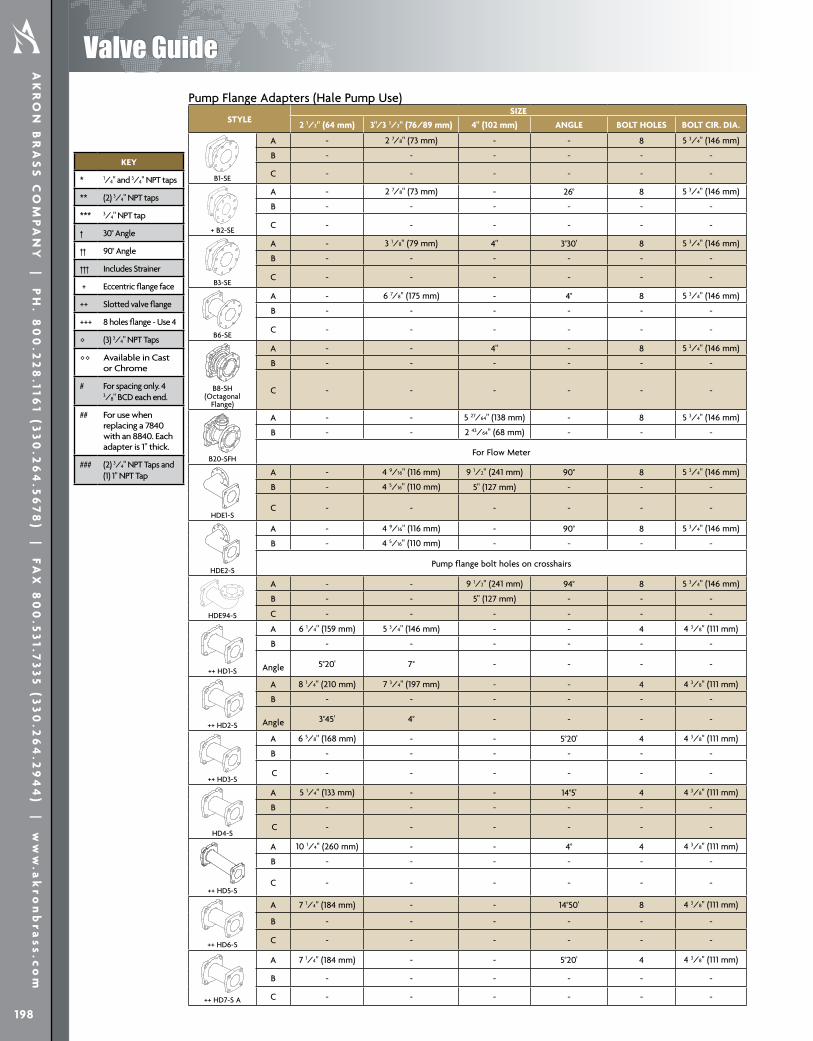
Pump Flange Adapters (Hale Pump Use)
STYLESIZE
2 1/2" (64 mm) 3"/3 1/2" (76/89 mm) 4" (102 mm) ANGLE BOLT HOLES BOLT CIR. DIA.
B1-SE
A - 2 7/8" (73 mm) - - 8 5 3/4" (146 mm)
B - - - - - -
C - - - - - -
+ B2-SE
A - 2 7/8" (73 mm) - 26° 8 5 3/4" (146 mm)
B - - - - - -
C - - - - - -
B3-SE
A - 3 1/8" (79 mm) 4" 3°30' 8 5 3/4" (146 mm)
B - - - - - -
C - - - - - -
B6-SE
A - 6 7/8" (175 mm) - 4° 8 5 3/4" (146 mm)
B - - - - - -
C - - - - - -
B8-SH(Octagonal
Flange)
A - - 4" - 8 5 3/4" (146 mm)
B - - - - - -
C - - - - - -d41663
d42017
d42344
dsk2790 d40409
B20-SFH
A - - 5 27/64" (138 mm) - 8 5 3/4" (146 mm)
B - - 2 43/64" (68 mm) - - -
For Flow Meter
HDE1-S
A - 4 9/16" (116 mm) 9 1/2" (241 mm) 90° 8 5 3/4" (146 mm)
B - 4 5/16" (110 mm) 5" (127 mm) - - -
C - - - - - -
HDE2-S
A - 4 9/16" (116 mm) - 90° 8 5 3/4" (146 mm)
B - 4 5/16" (110 mm) - - - -
Pump flange bolt holes on crosshairs
HDE94-S
A - - 9 1/2" (241 mm) 94° 8 5 3/4" (146 mm)
B - - 5" (127 mm) - - -
C - - - - - -
++ HD1-S
A 6 1/4" (159 mm) 5 3/4" (146 mm) - - 4 4 3/8" (111 mm)
B - - - - - -
Angle 5°20' 7° - - - -
++ HD2-S
A 8 1/4" (210 mm) 7 3/4" (197 mm) - - 4 4 3/8" (111 mm)
B - - - - - -
Angle 3°45' 4° - - - -
++ HD3-S
A 6 5/8" (168 mm) - - 5°20' 4 4 3/8" (111 mm)
B - - - - - -
C - - - - - -
HD4-S
A 5 1/4" (133 mm) - - 14°5' 4 4 3/8" (111 mm)
B - - - - - -
C - - - - - -
++ HD5-S
A 10 1/4" (260 mm) - - 4° 4 4 3/8" (111 mm)
B - - - - - -
C - - - - - -
++ HD6-S
A 7 1/4" (184 mm) - - 14°50' 8 4 3/8" (111 mm)
B - - - - - -
C - - - - - -
++ HD7-S A
A 7 1/4" (184 mm) - - 5°20' 4 4 3/8" (111 mm)
B - - - - - -
C - - - - - -
Pump Flange Adapters (Waterous Pump Use)
STYLE SIZE
2" (51 mm) 2 1/2" (64 mm) 3"/3 1/2" (76/89 mm) 4" (102 mm) ANGLE BOLT HOLE BOLT CIR. DIA.
B1-S
A 2 5/8" (67 mm) 2 5/8" (67 mm) 2 7/8" (73 mm) - - 4 (8 on 2") 4 3/8" (111 mm)
B - - - - - - -
C - - - - - - -
B1-SX
A - 2 5/8" (67 mm) - - - 4 slots 4 3/8" (111 mm)B - - - - - - -
C - - - - - - -
B3-SBoth flanges 4 3/8"
BCD
A - 2 5/8" (67 mm) - - - 8 4 3/8" (111 mm)B - - - - - - -
Not for valve attachment
+++ B4-S
A - 2 5/8" (67 mm) 2 7/8" (73 mm) - - 8 4 3/8" (111 mm)B - - - - - - -
C - - - - - - -
B5-S
A - 4 5/8" (117 mm) - - - 4 slots & 4 holes 4 3/8" (111 mm)
A - - 4 1/2" (114 mm) - - 4 slots 4 3/8" (111 mm)B - - - - - - -
+++ B6-S
A - 6" (152 mm) - - - 8 4 3/8" (111 mm)B - - - - - - -
C - - - - - - -
B7-S
A - 5.5" (140 mm) - - - 4 slots & 4 holes 4 3/8" (111 mm)
B1-SH
A -5/8"-1 1/8"
(16-29 mm)
11/16"-1 3/16" (17-30 mm) - 4° 8 6 5/8" (168 mm)
B - - - - - - -
C - - - - - - -
B1-SH (4")
A - - - 2" Total (51 mm) 4° 8 6 5/8" (168 mm)B - - - - - - -
C - - - - - - -
B2-SH
A - 11/16" (17 mm) - - - 4 4 3/8" (111 mm)B - - - - - - -
C - - - - - - -
STYLESIZE
2 1/2" (64 mm) 3"/3 1/2" (76/89 mm) 4" (102 mm) ANGLE BOLT HOLES BOLT CIR. DIA.
VALVE DOWN
++ HD21-SF UP or DN
For Flow Meter
A 6 1/4" (159 mm) - - 5°20' 4 4 3/8" (111 mm)
B 3 1/8" (79 mm) - - - - -
C - - - - - -
++ SE1-S
A 3 1/4" (83 mm) 2 3/4" (70 mm) - 90° 4 4 3/8" (111 mm)
B 5 1/4" (133 mm) 6" (152 mm) - - - -
C - - - - - -
++ SE2-S
A 5 1/4" (133 mm) 4 3/4" (121 mm) - 90° 4 4 3/8" (111 mm)
B 5 1/4" (133 mm) 6" (152 mm) - - - -
C - - - - - -
++ SE3-S
A 2 1/2" (64 mm) - - 90° 4 4 3/8" (111 mm)
B 7 3/4" (197 mm) - - - - -
C - - - - - -
SE4-S
A 8.5" (216 mm) - - - 4 4 3/8" (111 mm)
B 6" (152 mm) - - - - -
C - - - - - -
d41663
d42017
d42344
dsk2790 d40409
DE3-S
A - 4 15/16" (125 mm) 4 15/16" (125 mm) 94° 8 5 3/4" (146 mm)
B - 5 3/16" (132 mm) 5" (127 mm) - - -
C - - - - - -
Pump Flange Adapters (Hale Pump Use) ...Continued
KEY
* 1/4" and 3/4" NPT taps
** (2) 3/4" NPT taps
*** 3/4" NPT tap
† 30° Angle
†† 90° Angle
††† Includes Strainer
+ Eccentric flange face
++ Slotted valve flange
+++ 8 holes flange - Use 4
◊ (3) 3/4" NPT Taps
◊◊ Available in Cast or Chrome
# For spacing only. 4 3/8" BCD each end.
## For use when replacing a 7840 with an 8840. Each adapter is 1" thick.
### (2) 3/4" NPT Taps and (1) 1" NPT Tap
199
Valve GuideTechnical D
ata

STYLE SIZE
2" (51 mm) 2 1/2" (64 mm) 3"/3 1/2" (76/89 mm) 4" (102 mm) ANGLE BOLT HOLE BOLT CIR. DIA.
B3-SH
A - -13/16"-1 11/32" (21-34 mm)
- 4° 47 25/32"
(198 mm)B - - - - - - -C - - - - - - -
B3-SH (4")
A - - - 2" Total (51 mm) 4° 47 25/32" (198
mm)B - - - - - - -C
B1-SWClamps
A - 1 27/32" (47 mm) 1 27/32" (47 mm) - - 4 4 3/8" (111 mm)B - - - - - - -
C - - - - - - -
+ B2-SW
A - - 2 7/8" (73 mm) - 26° 8 5 1/2" (140 mm)B - - - - - - -
C - - - - - - -
B3-SW
A - - 3 1/8" (79 mm) - 4° 8 5 1/2" (140 mm)B - - - - - - -
C - - - - - - -
B4-SW
A - - 5" (127 mm) - 4° 8 5 1/2" (140 mm)B - - - - - - -
C - - - - - - -
B8-SW
A - - - 4" (102 mm) - 8 5 1/2" (140 mm)B - - - - - - -
C - - - - - - -
+++ B1-SEW
A - - 2 7/8" (73 mm) - - 8 5 1/2" (140 mm)
B10-SF
A - 3 1/2" (89 mm) 3 9/32" (83 mm) - - 4 4 3/8" (111 mm)B - 1 51/64" (46 mm) 1 3/8" (35 mm) - - - -
For Flow Meterd41663
d42017
d42344
dsk2790 d40409
B20-SFW
A - - -5 27/64" (138
mm) - 8 5 1/2" (140 mm)
B - - - 2 43/64" (68 mm) - - -
For Flow Meter
WDE1-S
A - - 4 9/16" (112 mm) 9 1/2" (241 mm) 90° 8 5 1/2" (140 mm)B - - 4 5/16" (110 mm) 5" (127 mm) - - -
C - - - - - - -
WDE94-S
A - - -9 1/2" (241
mm) 94° 8 5 1/2" (140 mm)
B - - - 5" (127 mm) - - -
C - - - - - - -
Pump Flange Adapters (Waterous Pump Use) ...Continued
KEY
* 1/4" and 3/4" NPT taps
** (2) 3/4" NPT taps
*** 3/4" NPT tap
† 30° Angle
†† 90° Angle
††† Includes Strainer
+ Eccentric flange face
++ Slotted valve flange
+++ 8 holes flange - Use 4
◊ (3) 3/4" NPT Taps
◊◊ Available in Cast or Chrome
# For spacing only. 4 3/8" BCD each end.
## For use when replacing a 7840 with an 8840. Each adapter is 1" thick.
### (2) 3/4" NPT Taps and (1) 1" NPT Tap
AK
RO
N B
RA
SS
CO
MP
AN
Y | P
H. 8
00
.22
8.116
1 (33
0.2
64
.56
78
) | FA
X 8
00
.53
1.73
35
(33
0.2
64
.29
44
) | ww
w.a
kro
nb
ras
s.c
om
200
Valve Guide

Pump Flange Adapters General Use
STYLE SIZE
2" (51 mm) 4" (102 mm) ANGLE BOLT HOLE BOLT CIR. DIA.
d41663
d42017
d42344
dsk2790 d40409
d41663
d42017
d42344
dsk2790 d40409
## B10-SP
A -2"
(50 mm)- 4
7 1/16" (179 mm)
B - - - - -
C - - - - -
+++ DE1-S
A3 3/4"
(95 mm)9 1/2"
(241 mm) 90° 8 4 3/8" (111 mm)
B 4 13/16" (122 mm)
5" (127 mm)
- - -
C - - - - -
+++ DE2-S
A 3 3/4" (95 mm) - 90° 8 4 3/8"
(111 mm)
B 5 1/2" (140 mm) - - - -
C - - - - -
Pump Flange Adapters Darley Pump Use
STYLE
SIZE
2 1/2" (64 mm) 3"/3 1/2" (76/89 mm) ANGLE BOLT HOLE BOLT CIR. DIA.
B2-S
A2 5/8"
(67 mm)2 7/8"
(73 mm) - 44 19/32"
(117 mm)
B - - - - -
C - - - - -
DD1-S
A6 1/4"
(159 mm)5 3/4"
(146 mm) 6° 44 19/32"
(117 mm)
B - - - - -
C - - - - -
C
A = Overall length B = Length to centerline of drain hole C = Length to edge of drain boss
BA
A = Valve flange to centerline of elbow B = Pump flange to centerline of elbow
Discharge & Intake Adapters Pump Elbow Adapters
Valve Dimension KeyKEY
* 1/4" and 3/4" NPT taps
** (2) 3/4" NPT taps
*** 3/4" NPT tap
† 30° Angle
†† 90° Angle
††† Includes Strainer
+ Eccentric flange face
++ Slotted valve flange
+++ 8 holes flange - Use 4
◊ (3) 3/4" NPT Taps
◊◊ Available in Cast or Chrome
# For spacing only. 4 3/8" BCD each end.
## For use when replacing a 7840 with an 8840. Each adapter is 1" thick.
### (2) 3/4" NPT Taps and (1) 1" NPT Tap
B
A
201
Valve GuideTechnical D
ata