value-driven business in the cloud
DESCRIPTION
Over the past few years we have witnessed how the Cloud technologies have rapidly evolved and many companies have transformed their business towards global, value-driven business in the Cloud. Many services have found a place in the Cloud and numerous new innovations currently exist and will continue to be based on the Cloud technologies. At the same time, the transformation from the traditional approaches towards Cloud-based business has resulted in major changes in ICT companies. DIGILE’s Cloud Software Program (CSW) was initiated in 2010. CSW is the largest collaborative program in the field of ICT in Finland. The four-year program includes several partners from Finnish industry and research organisations. VTT Technical Research Centre of Finland has been one of the main research partners of the program. VTT’s researchers have been working in a number of industry-driven business cases in collaboration with the companies and academic partners. The research cases have been challenging and have required a solid understanding of software business, processes, tools and methods from a variety of viewpoints. The Cloud Software consortia has achieved great results and generated real business value for many companies. Some of the examples and highlights are presented in this book.TRANSCRIPT

VIS
IONS•SCIENCE•TECHNO
LOG
Y•R
ESE
ARCHHIGHLIGHTS
•
eEngineering 2009—2012
In addition to industrial production, the success of Finnish industry is based strongly on the design and engineering of devices, working machines, manufacturing plants, power plants, process machinery and ships for global markets. At the same time, digitisation has become ever more vital to the success of industrial production and engineering and the volume, value and importance of the digital, virtual realm is increasing dramatically compared to physical plants and machines.
At the beginning of the 2010s traditional heavy industry accounted for 75% of the total value of Finnish exports, up notably from 57% in 2000. To reduce the design and production ramp-up times by half, VTT’s eEngineering spearhead programme (2009-2012) developed technology platforms for modelling and simulation, design knowledge management, life-cycle management, and human-technology interaction. The highlights of the research carried out during the programme are presented in this publication.
The most signifi cant achievement of the programme is Simantics, an extensive operating system providing an open, high-level application platform on which different computational tools can be easily integrated to form a common envi-ronment for modelling and simulation. Programme also enabled successful integration of user’s sound and noise experience and thermal comfort modelling to design of machine cabins in a virtual the design environment.
ISBN 978-951-38-8125-2 (print)ISBN 978-951-38-8126-9 (online)ISSN-L 2242-1173ISSN 2242-1173 (print)ISSN 2242-1181 (online)
8
VT
T R
ES
EA
RC
H H
IGH
LIG
HT
S 8
eEngineering 2009—
2012
eEngineering 2009—2012
Digitising the product process


VTT RESEARCH HIGHLIGHTS 8
eEngineering 2009—2012
Digitising the product process
RH_8_eEngineering.indd 1 26.8.2013 14:49:21

ISBN 978-951-38-8125-2 (print)ISBN 978-951-38-8126-9 (online)
VTT Research Highlights 8
ISSN-L 2242-1173ISSN 2242-1173 (print)ISSN 2242-1181 (online)
Copyright © VTT 2013
PUBLISHERVTT Technical Research Centre of FinlandP.O. Box 1000 (Tekniikantie 4 A, Espoo)FI-02044 VTT, FinlandTel. +358 20 722 111, fax + 358 20 722 7001
EDITORS: Kaisa Belloni, Olli VentäGRAPHIC DESIGN: Tuija Soininen
Printed in Kopijyvä Oy, Kuopio 2013
RH_8_eEngineering.indd 2 26.8.2013 14:49:21

3
Foreword
At the beginning of the 2010s traditional heavy industry accounted for 75% of the total value of Finnish exports, up notably from 57% in 2000. In addition to industrial production, the success of Finnish industry is based strongly on the design and engineering of devices, working machines, manufacturing plants, power plants, process machinery and ships for global markets.
Digitalization has become ever more vital to the success of industrial produc-tion and engineering. In practice, it has enabled the creation and exploitation of a digital continuum of engineering and opera-tive computer-based systems. For instance, requirements analysis and conceptual design are carried out with the aid of specific com-puter-based tools. Product and system design are carried out by a multitude of different soft-ware tools, often referred to collectively as CAD (computer-aided design) tools, with each field of technology and engineering using its own specific tool sets. Engineering software has also steadily evolved into extensive product life cycle management (PLM) systems with CAD and product data management (PDM) sub-systems at their core. Engineering is followed by manufacturing or construction and deliv-ery, managed again by specific engineering or manufacturing control software. Thereafter, the product or system enters its intended indus-trial use and, depending on the case, effective operation is governed, for example, by sen-sor or actuator systems, machine or process control systems, wider automation, condition monitoring, or quality management systems.
At a higher level, production planning, enter-prise resource management (ERP) systems, and even cross-machine management sys-tems and networked business management systems, may be used.
This continuum of engineering and opera-tive computer-based systems provides the foundation for the digitalization of industry. Computers, software and ICT systems have long been used by all industries. Neverthe-less, it is more acute than ever to really talk dually about virtual plants or machines and real plants or machines. The volume, value and importance of the digital, virtual realm is increasing dramatically compared to physical plants and machines.
Today, everything done in or for a modern plant is managed by or with the help of software and ICT systems. Therefore being competitive, efficient, flexible, innovative, experienced, professional or knowledgeable in the virtual realm are key competitive factors for modern industries.
In VTT’s eEngineering spearhead pro-gramme, ‘Digital product process as a success factor for technology industries’, success is defined as having: a) flexible and comprehensive design and engineering pro-cesses, b) faster deliveries and engineering throughput despite the increasing complexity and size of engineering contents, c) effective accumulation of engineering knowledge and
RH_8_eEngineering.indd 3 26.8.2013 14:49:21

4
reuse of proven solutions, d) efficient manage-ment of growing complexities, engineering projects, and processes, and f) ascertained quality. Meeting each of these key criteria to its fullest extent is an undertaking far beyond the scope of this research programme and requiring a vast range of digitalization tools and systems. The focus of the eEngineering programme was therefore limited to the fol-lowing core areas:1. Simulation-based engineering2. Knowledge-based engineering, and3. Interoperability of engineering systems.
The official programme period for eEngi-neering was from 2009–2012, although some projects are still on-going in 2013. The pro-gramme included around 100 projects in total, the majority of which were funded by VTT or jointly, for example by the EU or the Finnish Funding Agency for Technology and Innovation (Tekes), or partly or wholly by private compa-nies. The programme had a total budget of around EUR 40 million, representing about 350 person years. This issue of Research Highlights focuses mainly on strategic areas of VTT funding within the programme.
By the beginning of 2009, VTT already had significant assets in digital engineering based on its long tradition in leading-edge modelling and simulation research. The successful APROS (Advanced Process Simu-lation Software) environment, for example, is the culmination of more than 20 years of dedi-cated research and development in dynamic process simulation by VTT and its partners. Based on R&D revenues alone, APROS has been VTT’s single most valuable ICT software product. VTT’s BALAS steady-state simula-tor developed primarily for the pulp and paper industry has also achieved similar success. For detailed process simulation VTT has used and developed a number of CFD (compu-tational fluid dynamics) packages, and has also used a wide range of FEM (finite element method) software for mechanical analyses. In system-level simulation the Modelica family
has been growing fastest, and VTT is a long-standing member of the Modelica Association. VTT has also been active in conducting life cycle analyses (LCA, carbon footprint calcu-lations, etc.) and developing LCA software. For the machine industry, VTT has developed extensively instrumented virtual studios for conducting user experience simulations cov-ering animations, acoustics, thermal comfort, safety, and ergonomics. Given this back-ground, the programme implementation was targeted towards process and mechanical engineering and, furthermore, to their most challenging engineering tools, such as model-ling & simulation and engineering tools co-use.
Product or system platforms are a mod-ern means of building needed modularity and efficiency while at the same time enabling high flexibility and tailorability with respect to needs. Platforms also provide a means of accumulating knowledge, managing applica-tion complexity, and ensuring quality. As the eEngineering programme demonstrates, the benefits of platforms can also be realized in research, by enabling separate research outcomes, such as methods, algorithms, analysers, and simulators, to be effectively combined to produce synergistic applications. Information exchange across these applica-tions can be made seamless and live, where changes in one domain can be effectively proliferated across tool databases, and where design items can be made readily avail-able transparently or via transforms wherever needed. Single and isolated research tools may be interesting but greater value can be obtained from individual research tools by integrating them into strategic application platforms. In technical domains, the wider contexts of systems such as the CAD or open source tools mentioned above are also essential and multiply the value of research-based tools. Platforms are also middleware systems, meaning that many features that are necessary for most, if not all, tools need to be implemented only once as components of the middleware and be reused elsewhere.
RH_8_eEngineering.indd 4 26.8.2013 14:49:21

5
Examples include graphical configuration edi-tors, interfaces to third-party systems, support for multi-user editing, and security and privacy features. The use of simulators can be based on CAD system input or exchange of data, which is important for increasing user confi-dence and lowering the threshold for wider use of simulators.
The most significant achievement of the programme is Simantics, an extensive oper-ating system providing an open, high-level application platform on which different com-putational tools can be easily integrated to form a common environment for modelling and simulation. The development of Siman-tics began under a previous VTT programme, Complex Systems Design, which provided the basic template for the current platform.
A core part of the eEngineering pro-gramme involved further developing the template version and directly building the ele-ments of the Simantics platform. Alongside this, several existing simulator or tool compo-nents also needed considerable development
in order to become fully integrated or compat-ible with the growing Simantics environment. Other separate simulator and tool develop-ment projects affiliated with the spearhead programme also contributed to the evolution and design of Simantics.
Despite a strong emphasis on the development of Simantics and its respec-tive simulator components, the commercial VirtoolsTM environment remained the integra-tion platform of choice for the majority of new engineering areas for virtual machine cabins, such as auralization (sound and noise experi-ences) and thermal comfort. The challenges related to the platform components and to our understanding of the interactions involved led us not to test Simantics compatibility dur-ing the early stages of the programme. The Virtools environment also served well as a means of interfacing with the virtual studio infrastructure.
In 2013, the advantages and potential of the programme have become evident, as summarized in the following:
RH_8_eEngineering.indd 5 26.8.2013 14:49:25

6
• Process and automation designer’s working environment extended by a powerful and versatile simulation environ-ment, enabled by the Simantics platform.
• Extended workbench supports a wide range of simulation-based design stages and purposes, e.g.: a) Early process dimensioning aided by simple steady-state simulation, b) Detailed design iterations by dynamic APROS or even finer FEM or CFD, c) Early automation concept testing and later actual automa-tion system testing against appropriate level simulators, d) Process simulator assisted operator training and system troubleshooting.
• Seamless and transparent bi-directional exchange of CAD and simulator data, allowing an iterative working approach across tools as engineering solutions evolve. Key CAD software features, such as version control, externally accessible to simulators (no need to implement sep-arately in simulators.)
• Opens a range of possibilities for auto-matic generation of automation systems and generation of process details.
• Automation systems can be proven per-fectly correct by proper methods, such as formal model checking, and based on commercially available design tools.
• Combination of design, simulation and life cycle assessment (LCA) opens new development possibilities. In addition to performing traditional analyses and ben-efitting from existing model libraries and LCA databases, gaps in LCA data can be compensated by simulated output of power plants, manufacturing sites, etc., and the weaknesses of light LCA systems compensated by CAD con-nectivity, advanced user interfaces, and other strengths of a combined environ-ment.
eEngineering is built on and has ben-efitted greatly from previous VTT research
programmes and projects, and this successful leveraging will continue to be applied in future programmes. One current example is VTT’s Multidesign programme, which is aimed at developing a full chain of simulators spanning from fine atomic and material grid structures and the many levels of product structure to the industrial service business level. The Sim-antics platform offers a powerful means for implementing the necessary model interac-tions and integrations. Another example is the Smart Grid programme, which is conducting extensive research on distributed small energy production by wind turbines, solar systems, household energy sources, etc., and on advanced and more accurate energy use by consumers, vehicles, offices and industry. A wide range of simulator types are needed to study the challenges and scenarios presented by the smart grid concept. Simantics is an ideal platform for drawing all of these elements together.
During the eEngineering programme we had the opportunity to cooperate with many research and development organizations, enterprises and professionals in Finland and abroad. This cooperation has been mutually inspiring and productive. I wish to thank the funding organizations, most notably Tekes and the EU, and also our partner organizations, most notably the Finnish Metals and Engineer-ing Competence Cluster (FIMECC). Last but not least, my sincere thanks to the project teams and outstanding individuals who have contributed so much to eEngineering.
Olli VentäProgramme Manager
RH_8_eEngineering.indd 6 26.8.2013 14:49:26

7
Contents
Foreword ................................................................................................................................ 3
Contents ................................................................................................................................. 7
Simantics – an open source platform for modelling and simulationSimantics – blurring the boundaries of modelling and simulation .................................. 11Virtual plant combines engineering tools for the process industry ................................ 17Virtual machines smooth the way from traditional product development to seamless simulation-based life cycle management ........................................................... 22Analysing our environmental impact – real and virtual .......................................................... 31Error-free software through formal methods .......................................................................... 37
Designing user experience for the machine cabin of the future ............................................ 45
RH_8_eEngineering.indd 7 26.8.2013 14:49:26

8
Authors
Tommi Karhela Pasi Laakso Research Professor Senior Scientist
Juha Kortelainen Tuomas Helin Antti PakonenPrincipal Scientist Researh Scientist Researh Scientist
RH_8_eEngineering.indd 8 26.8.2013 14:49:33

9
Simantics — an open source platform for modelling and simulation
RH_8_eEngineering.indd 9 26.8.2013 14:49:33

10
RH_8_eEngineering.indd 10 26.8.2013 14:49:33

11
Simantics — an open source platform for modelling and simulation
Simulation offers proven advantages as a tool for modern decision making. In industry, simulation is widely used in virtual prototyping, simulation-aided design and testing as well as in training and R&D. However, obstacles to wider utilization of modelling and simulation still remain.
Current modelling and simulation (M&S) tools exist as separate systems and are not integrated with other information management networks. They do not inte-grate well enough with commonly used software systems, such as CAD, PLM/PDM, ERP, or with control systems. Co-use of the simulation tools themselves is poor, and the modelling process as a whole is often considered too laborious.
The Software as a Service (SaaS) and Open Source business models, used widely in consumer markets, are also entering the mod-elling and simulation world. The closed source licensing model is considered problematic, especially in public decision making where the whole computational model should be as openly available as possible.
To address the boundaries between modelling and simulation, VTT developed Simantics, an integration technique and platform implementation which has been published as open source software.
Simantics – blurring the boundaries of modelling and simulation
AUTHOR: Tommi KarhelaTitle: Research Professore-mail: [email protected]
Design (CAD) and simulation system integrationDesign systems (CAD) and simulation systems have traditionally been separate in many areas of engineering. Notable exceptions include electronic circuit design and piece goods manufacturing processes, where simulation-aided design has long been in use. The reason for this is also evident. The more deterministic the target production process is, the easier it has been to utilize computational models.
In many engineering sectors – such as the process and construction industries – 2D and 3D CAD systems have already been used for decades, but these systems do not include integrated simulation features. Instead, numer-ous separate computational tools are utilized in different phases of the engineering process.
Common operating environment for combining M&S toolsThere are many simulation solvers used both in academia and industry that have sophisticated computational algorithms, but lack an effec-tive operating environment. There is a current need for common operating environments and pre- and post-processing capabilities as well as connections to other applications such as design and control systems.
Pre-processing capabilities include fea-tures such as 2D-fowsheeting support or 3D-geometry definition support, discretiza-tion support (meshing) as well as support for model validation, model structure browsing and editing, model component reuse, model documentation and searching, experiment
RH_8_eEngineering.indd 11 26.8.2013 14:49:33

12
configuration, model version control and team features.
Post-processing capabilities include fea-tures such as 2D-charts and 3D-visualization of results, 2D and 3D animation of results, and experiment control visualization. As these are generic requirements, it is inefficient for dif-ferent parties to maintain their own individual operating environments. Instead, a single common framework could be implemented which could be jointly maintained and further developed.
Co-use between different computational toolsThe need for co-use of different simulation models arises from the same need for design system integration explained above. The prod-ucts and production processes modelled are complex. Heterogeneous multi-level models are needed which can be utilized across dif-ferent engineering disciplines. In addition to
Figure 1. The Simantics platform demonstrates its strength in easing communication between different design and simulation disciplines by enabling smooth data transfer and information exploitation from design tools to simulation tools and vice versa.
supporting different levels of detail, users also need to combine optimization and model uncertainty assessment into their simulation experiments. In order to break the boundaries between different computational tools, con-figuration and simulation run-time integration is needed.
Team features in M&SModelling and simulation environments are used and developed by extremely het-erogeneous user populations. Some users develop new, more efficient solvers and data structures, others design reusable model libraries or use these libraries to model real-world systems, while others simply use these ready configured models to support decision making. The team features of a simulation environment should not support any one user level alone, they are needed in and across all of these levels. The features should enable as efficient as possible reuse of model assets.
RH_8_eEngineering.indd 12 29.8.2013 16:01:08

13
Simantics — an open source platform for modelling and simulation
This requires an infrastructure for publishing and sharing model components with others within the same model, project or company, or even more publicly.
There has been a significant shift in the software business toward open source and software as a service business models. For example, in the US most software startups that are venture-funded utilize these business models. The same models are also penetrat-ing the field of modelling and simulation. It is likely that future modelling and simula-tion business will no longer be in platform solutions, but in simulation components and services running on open operating systems for modelling and simulation. This openness also means that a neutral democratic forum for decision making on maintenance and further development has to be established.
VTT’s Simantics platform has been pub-lished as an open source environment under the Eclipse Public License (EPL). To support democratic decision making, VTT and part-ners have established a Simantics Division under the Association of Decentralized Information Management for Industry (THTH). At the time of writing, there are 25 company, university and research institute members in the association.
Main technological innovations of the Simantics platformThe cornerstone of the Simantics architec-ture is its open and extensible semantic data model, which is used to represent the operating environment and the simulation and modelling results. The data model is semi-structured, which means that the data contains the rules regarding its own struc-ture. The approach shares similarities with W3C RDF and OWL, but is especially tailored for use with engineering and simulation mod-els. The semi-structured approach allows the co-existence of different interlinked data models, which can also be augmented with new pieces of data when needed. This data-
centric approach places an emphasis on high quality representation, which increases the usefulness of the produced results. Simantics comes with standard models developed for common simulation and modelling patterns. As an example, a generic conceptualization of hierarchical, connected and parameterized models can be used as a basis for differ-ent domain models. The data models are organized in layered conceptualizations, i.e. ontologies, which can be developed before or during modelling.
As an operating system for modelling and simulation, Simantics needs to be able to handle various data models related to different tools, computational methods and modelling methodologies. Successful co-use of these different domain services requires power-ful integration and mapping tools between the different models. Simantics addresses these needs by supplying an ontology-based mapping framework for mapping and trans-
Whereas modelling and simulation is used widely in design and development, it has yet to gain a foothold in operational decision making. In this area, simulation models are connected to measurements from real systems and predictions are made to support actual decisions. Co-use of simulators and control systems sets requirements for the real-time communication, synchronization and simulation control facilities of the integration platform. If these are implemented in a neutral and efficient way, they can also provide a solid base for the communication and synchronization of different dynamic simulation tools or for the high-level parallelization of several simulation experiments. High-level parallelization here refers to process-level parallelization i.e. several simulator instances running in parallel, not to code-level parallelization of a single simulator. High-level parallelization is also useful in optimization and uncertainty quantification assessment cases.
RH_8_eEngineering.indd 13 29.8.2013 16:01:08
14
forming models within Simantics. The general approach is to import domain models into Simantics as they are, and then transform the data further by using semantic mechanisms, which have been studied for some time [e.g. 1, 2, 3]. The advantage of this approach is that each specific data model is kept clean and separate. Elaborate data transformation mechanisms are also useful for generating models from other models. From the use case point of view, the mechanisms for mapping and transformation enable the co-use of dif-ferent domain models as well as the co-use of models of different levels of detail. Simantics offers the user a special Simantics Constraint Language (SCL) for developing user config-urable mappings and transformations. The same functional programming language can be used, for example, for semantic queries and model validation.
The use cases for modelling needs in a data-driven simulation and modelling sys-tem are highly versatile. In addition, the semantic data modelling approach is heavy performance-wise. To be able to fully establish a semantic data driven modelling approach, Simantics supports a wide range of mecha-nisms for extending the application range of the semantic data model. Simantics offers seamless support for four levels of persistence of semantic data in a unified model. Memory persistent parts of semantic data can be used to model quickly changing and transient struc-tures, so that the structures only exist during a modelling session. Workspace persistent structures are only stored in the user’s local hard disk and can be used to represent vari-ous cache or preference structures, which are generated or otherwise not publishable to all users of the distributed database. Database persistent parts of the data model are shared by different clients of a database server. Data-base persistent data is also fully versioned. Finally, database persistent data can also be published and synchronized between data-base servers, called team servers, across organizations.
The wide range of persistence levels and representations is common in simulation cases. For a semantically similar attribute we can have input values in engineering systems, permanent configuration values in simula-tion models, different sets of, for example, dimensioning values in simulation models, computed result values and time series, real-time dynamic simulation or measurement values, etc. The representation of values for the same attribute can be modelled in com-pletely different ways or not at all. Some attributes have many values, some are time-dependent, some are persistently stored and some are not. To fulfil the integration goals the system needs to be able to represent and manage all these different pieces of data and, most importantly, to associate the data semantically together so that the data can be integrated. Simantics addresses these issues through semantic modelling of variables and their values and simulation experiments and by specifying a software interface to be used to obtain values for a given configuration of semantically modelled variables. The inter-face defines a semantic connection from a data value to the concepts of the data model while allowing free acquisition of values from any source. In many cases the obtained val-ues are backed by the semantic data model, but can also be directly obtained from, for example, a simulator or measurement device. This framework for simulation data manage-ment makes Simantics unique among other data modelling platforms.
Simantics – an open operating system for M&S The benefits to industry of modelling and simu-lation are clearly proven, yet two key obstacles to the use of simulation still persist – cost and timely availability of simulation models. These are both the result of model develop-ment not being integrated into engineering work flow and data management. Recent cases have shown that a sufficient system-level model can be created based entirely
RH_8_eEngineering.indd 14 26.8.2013 14:49:37

15
Simantics — an open source platform for modelling and simulation
on engineering data. These case studies are explained in more detail in the next chapter. It has been additionally concluded that the co-use of different modelling and simulation tools is currently insufficient. Multi-scale models combining different levels of detail would ben-efit from better configuration integration and run-time co-use of different simulators. Fur-thermore, the co-use capabilities of simulation environments and real-time systems, such as control systems, are inadequate. The chal-lenge of integrating design system features, simulation features and real-time control and measurement features into the same software architecture has been identified. Current simu-lation environments also lack team features, which are essential in modern globally net-worked engineering projects.
VTT has introduced a solution that uti-lizes a semantic data modelling approach and combines this expressively powerful ontology-based design with fast acces-
sibility to simulation, measurement and control data. This data-driven approach opens possibilities for automatic model validation, reporting, processing, anno-tation and linking. The layered ontology structure enables expandability and reusabil-ity. The heart of the integration solution is an ontology-based mapping mechanism that enables rule-based synchronization of differ-ent engineering and simulation models. The idea is to integrate data from different background systems into the environment ‘as is’ using native data models. The model mapping is done inside the platform using ontology-based mapping rules. To address problems of scalability and processing speed – key bottlenecks in the semantic approach – the developed solution has been optimized for industrial use. The platform has been pub-lished under an open source license and is maintained jointly with industry partners in the form of an association.
Figure 2. Evolution of information management.
RH_8_eEngineering.indd 15 26.8.2013 14:49:40

16
References [1] Maedche, A., Motik, B., Silva, N. & Volz, R.
2002. MAFRA - A Mapping FRAmework
for Distributed Ontologies. Proceedings
of the 13th International Conference on
Knowledge Engineering and Knowledge
Management, Siguenza, Spain. Pp. 235–
250.
[2] Pierra, G. 2004. The PLIB Ontology-Based
Approach to Data Integration. Proceedings
of the IFIP 18th World Computer Congress,
Toulouse, France. Pp. 13–18.
[3] Qian, P. & Zhang, S. 2006. Ontology
Mapping Meta-model Based on Set and
Relation Theory. Proceedings of the First
International Multi-Symposiums on Com-
puter and Computational Sciences Volume
1 (IMSCCS’06), Hangzhou, China. Pp.
503–509.
Related publications Karhela, T., Villberg, A. & Niemistö, H. 2012. Open Ontology-based Integration Platform for Modeling and Simulation in Engineering. International Journal of Modeling Simulation and Scientific Computing, Volume 3, Issues 2: (1250004), World Scientific Press.
RH_8_eEngineering.indd 16 26.8.2013 14:49:40

17
Simantics — an open source platform for modelling and simulation
Process plant deliveries consist nowadays of two plant components – a ‘real’ plant and a ‘virtual’ plant. The real plant is the actual nuts and bolts delivery, while the virtual plant comprises all of the digital material handed over to the customer. However, a lack of proper standards and harmonized procedures regarding the content and delivery of virtual plants poses a number of challenges for system integrators (EPC contractors) – to the extent, in fact, that vir-tual delivery may be more challenging than the actual plant delivery itself.
A live or executable virtual plant combines a virtual plant, i.e. piping and instrumentation (P&I) diagrams, 3D models, automation models and electrical designs, together with simulation models and other computational algorithms. The live virtual plant has a wide range of potential uses throughout the life cycle of the facility, from the early design phases through to commis-sioning and operation support. Some of the most time-consuming tasks involved in live virtual modelling include the collection of the initial data needed to create simulation models and keeping this data up to date throughout the life cycle of the plant. There have previously been no readymade work processes, standards or tools for efficient simulation model generation. To address this problem, VTT has developed infor-mation model integration techniques that enable seamless bi-directional data flow between engineering systems and simula-tion models, facilitating the development
Virtual plant combines engineering tools for the process industry
AUTHOR: Pasi Laakso Title: Senior Scientiste-mail: [email protected]
of efficient working processes. This article gives an overview of two key development efforts in this area.
VTT has been developing simulation tools for the process industry for well over 25 years. Apros – a software platform for dynamic mod-elling and simulation – has been one of the biggest success stories in this area [1]. Apros has been used for simulation-assisted auto-mation testing [2], as a tool for automation modernization of the Loviisa nuclear power plant (see Figure 1), and in control concept development [3]. One of the main obstacles to wider utilization of these beneficial methods has been the amount of work needed to cre-ate and update simulation models. Now, there are new possibilities to solve the problem.
Accurate and up-to-date virtual plant models are becoming more common. EPC contractors have started to integrate EDMS (Engineering Data Management System) tools such as Comos or Intergraph SmartPlant as a part of their normal design procedure. Industry is also adopting more and more so-called intelligent CAD systems that provide online access to up-to-date databases that always contain the latest engineering data. Meanwhile, VTT has been developing the Simantics integration platform [4], which can be used to connect databases and simulators together, providing the basis for creating live virtual plants.
New techniques make it possible to take simulation into use earlier and use more detailed simulation models cost-effectively. Updating design data needed for simulation
OTHER CONTRIBUTING AUTHORS: Jari Lappalainen, Tommi Karhela, Marko Luukkainen
RH_8_eEngineering.indd 17 26.8.2013 14:49:40

18
Figure 1. Simulation is widely used in the Loviisa nuclear power plant automation renewal, e.g. to develop and test the new automation system and for operator training.
can be done automatically several times dur-ing the design process and using real design data every time.
Recent work in this area has focused on automatically generating simulation models based on design data, and then transfer-ring possible changes back to the plant engineering databases. The possibility of simulation-assisted preliminary planning has also been considered. In the latter case, the plant design database would be seeded with a design created in a simulator. A typical integra-tion project would include a technical solution for transferring design data and, more impor-tantly, finding correspondences between the data objects of the simulation model and the plant design database.
Case: Foster Wheeler Energia Oy – connecting Apros to Comos Foster Wheeler Energia Oy (FWE) has been using Apros simulation software for modelling boilers and related automation. They have also integrated Comos [5] as a part of their boiler
engineering process. VTT has been involved in the take-up process and has integrated dynamic process simulation as part of the engineering process by designing and imple-menting tools for integrating Comos and the Apros simulation tool. The developed tools transfer process and automation design data from the Comos database to the Apros simu-lator and generate or update the Apros model automatically.
The project began by analysing FWE’s existing simulation practices. Based on this, the integration tool requirements were iden-tified. Three potential levels of detail of the dynamic simulation model were considered. The first level – the conceptual level – con-tains the main process components and the pipelines between them and is usually tuned to match steady-state performance calcula-tion. Simulation at this level was considered most beneficial in the FWE case and also in future cases in general. The second level of detail, referred to as the basic level, is more detailed, corresponding to the level of
RH_8_eEngineering.indd 18 26.8.2013 14:49:45

19
Simantics — an open source platform for modelling and simulation
detail of a piping and instrumentation (P&I) diagram, with most pipes and similar heat surface groups described individually, and also including detailed automation diagrams. Simulation at this level is highly extensive and detailed, and has previously not been considered cost effective. The third level of simulation considered was the 3D level, in which even the smallest devices and pipes are modelled. This level of detail was not implemented.
Figure 2 shows the typical corre-spondence between a P&I diagram and a conceptual-level model. The P&I diagram on the left shows an economizer system and its header and pipe connections to other parts of the plant. Two pipe bundles are also described. The diagram shows only the water side (flue gas side is not shown). The corresponding Apros model is shown on the right. In the Apros model, the input header represents all input headers and pipes in the system combined and, likewise, the output header represents the output headers and pipes combined. Similarly, the pipe bundles identified in the P&I diagram are modelled as a single heat exchanger in the Apros model. The identification of system components is
based on the KKS power plant classification system.
A key challenge brought to light by the FWE project was a lack of readily available data for simulation model generation. This under-lines the importance of planning simulation tools and EDMS tools in parallel. For exam-ple, obtaining accurate elevation levels during the early design stages was problematic, as elevations are typically defined only later in the project during the detailed 3D design stage. It was also found that not all plant modelling practices were a suitable basis for simula-tion; for example, a P&I diagram might appear fully connected visually, but contain symbols that are not present in the plant model. When generating a simulation model, this results connections being missed. This shows that, in addition to appropriate and timely selection of tools, also further guidance of plant designers is needed.
‘Dynamic simulation with Apros has been valuable tool for us when investigating boiler plant configurations. Verifying and optimizing plant design decisions is an important part of the work process. When we started to integrate Comos as part of
Figure 2. Economizer P&I diagram and corresponding conceptual-level simulation model. The heat surfaces, i.e. pipes, in the middle generate heat exchanger in Apros. Headers and pipes entering and leaving the system are combined together as heat pipes in Apros.
RH_8_eEngineering.indd 19 26.8.2013 14:49:47

20
our design process, it was natural to also include connection to Apros as part of the Comos development.
Currently, we can develop the plant with our design tools, run steady-state analysis using our in-house dimensioning tool and then automatically generate Apros model for use in analyses requiring a dynamic sim-ulation model. Connection to our own boiler model can also be generated automatically. If the design changes, the model can be updated or regenerated easily. Now we can virtually test more design alternatives in a shorter time than before.’
-Jenö Kovacs, D.Sc., Principal Research Engineer,
Foster Wheeler Energia Oy
Case: Fortum – connecting Apros to SmartPlant In another on-going project, the Apros simula-tion tool is being integrated with Intergraph’s SmartPlant product family [6], particularly SmartPlant P&ID, SmartPlant Instrumenta-tion, and SmartPlant Foundation. The project shares many similar features to the previous FWE case concerning data transfer between process modelling and P&I diagrams. The project’s prime focus, however, is on simula-tion-based basic automation design and its integration with other SmartPlant engineering tools. Data transfer with SmartPlant is achieved through SmartPlant Foundation, which ena-bles electronic management of all of the plant’s engineering information, integrating data on physical assets, processes, and regulatory and safety imperatives. Apros is used as an automa-tion design tool, while SmartPlant Foundation acts as an integration platform between auto-mation, process and instrumentation planning. Typical automation design solutions and struc-tural automation components are accepted and taken into use by other developers through SmartPlant Foundation.
The integrated solution enhances the use of SmartPlant products by adding con-
trol design and Apros-based testing features to it. The integration also benefits SmartPlant owner operators by extending access to engi-neering asset data, including dynamic plant performance versus as-designed engineering data. The solution also enhances the use of Apros by enabling use of SmartPlant engi-neering data to create dynamic models more efficiently.
‘Fortum considers dynamic simulation as an essential tool in modern power engi-neering and foresees its role as clearly increasing in the future. Real breakthroughs can be achieved through seamless inte-gration between engineering project tools and simulation software. Besides technical integration capabilities, also a willingness to move towards new working methods is needed. Further development is needed, but we see great potential here. Embracing this approach could bring a competitive edge to the Finnish engineering sector. Fortum wants to be on the front line of this development, firstly as a company with a strong engineering tradition, and secondly, as a committed simulation provider for the power industry.’
-Sami Tuuri, Product Manager, Fortum
Discussion Dynamic simulation serves as a valuable tool in plant design and modernization, enabling, for example, automation and process design to be verified ahead of plant construction, and plant personnel to be effectively trained to operate the plant under normal and abnormal conditions.
This development provides a good basis for wider take-up of simulation in industry.
There is still work to do. The FWE/Comos integration project has progressed to the maintenance phase. The system has been successfully tested with completed engineer-ing projects, but with the emergence of new projects alterations to the current generation
RH_8_eEngineering.indd 20 26.8.2013 14:49:47

21
Simantics — an open source platform for modelling and simulation
The Simantics integration platform developed by VTT has been successfully used (see case Foster Wheeler above) to integrate the Apros simulation tool with the plant asset management software Comos and, in an ongoing Fortum collaboration, the platform is also being used to integrate Apros with SmartPlant Foundation. An integration between Aucoplan and Apros has also been developed in an earlier case [3]. Automatically generated models are free of manual copying errors, faster to generate and can be more detailed than normally possible.
rules are likely to be needed. Apros-Comos integrations also need to keep pace with the evolution of Comos. Deeper integration with SmartPlant is also currently under develop-ment ahead of the piloting phase. It should also be noted that as Comos and SmartPlant are intended to be used flexibly in different environments, a degree of tailoring is needed when applying the technology within new companies.
References[1] Apros web pages www.apros.fi
[2] Tahvonen, T., Laakso P., Wittig, J.,
Hammerich, K. & Maikkola, E. 2009.
Simulation Assisted Automation Test-
ing During Loviisa Automation Renewal
Project., 6th IFAC Symposium on Power
Plants and Power Systems Control, 5–8
July 2009, Tampere, Finland. Power
Plants and Power Systems Control, Vol-
ume 1 | Part 1., Pp. 314–319.
[3] Paljakka, M., Talsi, J. & Olia, H., 2009.
Experiences on the integration of auto-
mation CAE and process simulation tools
- case Fupros. Automaatio XVIII Semi-
naari 17.-18.3.2009, SAS, julkaisusarja
36. Finnish Society of Automation. Hel-
sinki.
[4] Simantics web pages www.simantics.org
[5] Comos web pages http://www.
automation.siemens.com/mcms/plant-
engineering-software/en/Pages/Default.
aspx
[6] SmartPlant Foundation web pages http://
www.intergraph.com/products/ppm/
smartplant/foundation/default.aspx
RH_8_eEngineering.indd 21 26.8.2013 14:49:47

22
The use of computational tools in product development is now standard practice in mechanical engineering and design. The development of a modern, complex high-technology product, such as a modern passenger car, aeroplane, or diesel engine, would be practically impossible without computer-aided design (CAD) systems, com-putational analyses, and system simulation. These provide the tools for designers to gain valuable feedback about the behaviour and performance of products under development. Rapid advances in computer technology and decreasing computational costs have made it possible for even small companies to incor-porate digital design and simulation into
their product develop-ment. At the same
time, the most a d v a n c e d c o m p a n i e s are tak-ing steps towards the vision of fully digital prod-
uct processes and digital man-
agement of all data, information, and
even knowledge related to their product pro-cesses. The vision includes digital functional product models that can be used to virtually test products and their behaviour from multi-
Virtual machines smooth the way from traditional product development to seamless simulation-based life cycle management
AUTHOR: Juha KortelainenTitle: Principal Scientiste-mail: [email protected]
ple engineering perspectives as well as data management solutions that enable engineers, designers, and other doers in the process to efficiently utilize all of the information involved in the product process.
The mechanical engineering research carried out under the eEngineering research programme focused on the concept of a sim-ulation-based product process covering the entire product life cycle and on the integration of data and engineering software applications into this process. One of the major findings of the programme was the importance of product information and related knowledge, and especially how data, information and knowledge are managed and in what form. Computational tools and systems often store data in forms that are not known or under-stood by their users, and not always even by the system managers – data simply goes into a database, and there it stays. However, together with engineering knowledge, the information contained in this data is essen-tial capital in the product process. This capital is often not systematically man-aged at all. The technologies developed in the eEngineering programme, such as the Simantics platform, provide means and practical tools for managing the valu-able information and knowledge of the product process. Another important insight was the need to expand the application of simulation beyond estimating the behaviour of physical systems to include non-physical
As the offering of different computational
tools, design systems and data management solutions
continues to surge, the need to separate data, information and knowledge from computational
tools is becoming increasingly evident.
RH_8_eEngineering.indd 22 26.8.2013 14:49:47

23
Simantics — an open source platform for modelling and simulation
systems and processes, such as the function of an organi-zation or the markets. Even though these simulations may not be perfectly accurate or fail-safe, they provide a similar learning experience as the simu-lation of physical systems provides to an engineer or designer. The modelling phase of the target system helps the user to understand the structure, relations, and scale of the components and phenomena involved in the system. By simulating the model, the user gains understanding of the behaviour and dynamics of the system and the interaction of its components and sub-systems. This applies to both physical and non-physical systems, and helps the user to design better products, processes and ser-vices.
From product development to simulation-driven life cycle process
VTT has an excellent van-tage position for viewing the landscape of Finnish and international industry. As a
neutral technology devel-oper and know-how producer,
VTT has a comprehensive under-standing of the use of computational
methods and tools in industrial product pro-cesses. The key challenge is strong case or conditions dependency. What is obvious to one industrial sector or company does not necessarily apply to others. We view a product process as a whole chain, including tools and systems, people and practices, the operating environment and the markets. A product pro-cess is not just about technology, but about everything related to the product life cycle.
The concept of applying simulation for
estimating the behaviour of physical systems can be extended to non-physical systems and processes, such as the function of the organization or the
markets.
RH_8_eEngineering.indd 23 26.8.2013 14:49:49

24
Development levels in the simulation-based product process
On the first level, simulation in product development, computational methods are used to study detailed and local phenomena (from the product perspective). At this level, computational methods typically have only a limited effect on product development, and most product development is carried out using traditional methods, i.e., engineering practices and established design principles. This is the prevailing practice in many mechanical engineering companies in Finland today.
On the second level, virtual prototypes in product development, the whole product or at least its main subsystems are modelled and simulated as virtual prototypes. This enables engineers to study the overall dynamics and behaviour of the system and gain important information at an early stage in the product process, before constructing any physical prototypes. Product development is still based on traditional engineering practices. Some companies in the mechanical engineering sector in Finland utilise this approach.
On the third level, simulation-based product development, similar computational methods are used as on the previous level, but now they are used systematically and form the basis of the design process. Before design work commences, the component, subsystem or product in question is modelled and simulated using a coarse model to gain understanding of the interactions and interferences involved. Based on this knowledge the design is then improved, and the procedure is continued iteratively until a design that fulfils the requirements is achieved. The challenge of this approach is in implementing this design process in practice. Only a few mechanical engineering companies in Finland operate on this level.
On the fourth level, simulation-based product process, the product modelling and simulation con-cept is also applied to the product process. This means that in addition to modelling the physical properties of the product, also the non-physical processes, such as the product maintenance business model and product development organization, are modelled and simulated. In addition, other important aspects, such as carbon and water footprint and other environmental effects, are analysed based on the available product data, and the life cycle performance of the product is optimized. This is still the future, although methods and tools to implement this level are already available.
VTT provides research and services in all key areas of the simulation-based product process con-cept.
Figure 1. Evolution of simulation use in the product process and the increasing importance of data
management. [2]
RH_8_eEngineering.indd 24 26.8.2013 14:49:55

25
Simantics — an open source platform for modelling and simulation
VTT’s long experience in applying com-putational methods and simulation in research and in industrial product development has pro-vided a unique understanding of how the use and development of computational methods evolve within an organization. This evolution process can be roughly divided into four lev-els, as illustrated in Figure 1. The objective of modelling and simulation is to gain better understanding of the systems in the product process and, ultimately, to create a ‘big pic-ture’ of not only the product, but the whole product life cycle. The different simulation methods and tools, optimization algorithms, and data integration solutions available are the pieces in this puzzle, which need to be col-lected, modified and combined in order for the big picture to be revealed.
The concept of the simulation-based product process, i.e., the use of computa-tional methods for simulating and analysing the whole product life cycle, and different approaches to software integration through a centralized data management system, were studied together with the Finnish Fund-ing Agency for Technology and Innovation (Tekes) in the joint-funded research project Computational models in product life cycle – Codes [1]. The project shed new light on the concept of simulation-based product life cycle management and the fact that the same justifications for utilizing simulation in studies of physical systems are also valid for larger-scale systems and processes. Another important finding was that we already have many of the pieces of the ‘big picture’ of whole life cycle simulation, and we have a good understanding of the parts needed to complete the rest of the puzzle. The project was carried out under VTT’s eEngineering programme as part of the national Digital Product Process research programme.
Simulation-based design requires strong data managementAs product processes become increasingly comprehensive, covering all process aspects
and business perspectives, effective product life cycle management at the product devel-opment and manufacturing stages is also becoming ever more important. Product data, information and related knowledge are the most valuable assets of the prod-uct process. The software applications and systems used to produce, modify and store data during the process have a direct impact on the functioning of the process. For exam-ple, the engineering software applications used in product and manufacturing design influence the working efficiency of the design engineers and, in turn, the end quality of the design. This is emphasized in the simulation-based product process, where the design of the product and the manufacturing process are based heavily on the results provided by the system simulation tools used and on the understanding gained from them. Also, as simulation and design are carried out iteratively, the amount of data gathered is extensive, and effective data exchange and data integration become essential.
Even though digital design and com-putational methods are widely used in mechanical engineering, design and simu-lation data exchange is still cumbersome in daily research and development work. Dif-ferent design systems and simulation tools use their own data formats and internal data models, which are not well-supported by other software applications. Switching
Computational methods provide a valuable tool for estimating the effects of design and strategy decisions in the early stages of the product process and thus enable overall optimization of the product and its related services. This requires strong solutions for product and design data management, especially in globally operating organizations.
RH_8_eEngineering.indd 25 26.8.2013 14:49:55

26
CAD systems mid-project can be a formidable undertaking due to data exchange issues and should preferably be avoided. Exchanging data between simulation soft-ware is in some cases totally impossible due to a lack of common data formats. This means that the software appli-cations used in the process have a strong effect on the daily work of the design engineer, and the choice of tools used deter-mines many outcomes later in the process. As an example, if structural analysis model-ling has been started with one commercial FEM software application, it can be very dif-ficult to switch later in the process to using a different, preferred FEM application for com-putations. In an ideal situation, modelling data would be independent of the com-putational tools used, and tool selection would be freely possible at the computa-tional analysis stage.
The general concept of separating product and design data from the tools used to produce, modify, and process it is illustrated in Figure 2. The concept also includes the management
of engineering knowledge in machine-understandable form.
According to the concept, all data, information and knowledge related to
the product process are managed and inter-preted by a centralized system. This ensures that product information is preserved even if the computational tools used are changed. In addition, the concept provides the freedom to choose the right tool for each purpose, thereby enabling the use of computational resources to be optimized. The centralized data man-agement approach allows all users to access up-to-date data, whether the organization is local or worldwide.
The vision of separating product data and computational tools, described above
Separating the product data and
the computational tools and systems ensures the preservation of product
information and provides the freedom to choose the best computational
tools.
Figure 2. The concept of separating valuable computational product data from the tools that use it.
RH_8_eEngineering.indd 26 26.8.2013 14:49:59

27
Simantics — an open source platform for modelling and simulation
and illustrated in Figure 2, requires a range of skills, systems and methods. Each com-putational method requires specific expertise to be gathered in order to reliably model and simulate complex physical systems. Running large computational analyses also requires large computational resources and systems capable of utilizing these resources. The vast amounts of numerical data produced by large-scale simulations need to be managed and used efficiently in the product process. These are considerable challenges in themselves and represent a major combined undertaking, but the benefits are compelling. The Simantics platform introduced in the previous article offers a solid basis for achieving these data management goals.
Case: Data architecture and software application integration through a centralized data management systemThe eEngineering programme studied and implemented the ‘big picture’, discussed in
the previous sections, in a number of areas. A general architecture for data and software application integration into a centralized data management system, such as the Simantics platform, was designed, and selected soft-ware applications and formats were integrated to determine the effort required for its imple-mentation and to understand the concrete process and its details. The data model and software application integration architecture is illustrated in Figure 3. The main design idea is that the data model of a software application or a file format, such as the Abaqus INPUT format, is created one-to-one in the Simantics platform as an ontology. The data from differ-ent software applications is integrated inside the Simantics platform using semantic data mapping based on general software appli-cation or domain ontologies (e.g., a generic FEM ontology). This approach simplifies the implementation of laborious software application integrations and enables the utilization of data mapping features of the semantic data representation approach.
Figure 3. Architecture of the integration of the simulation software applications into the common data management solution.
RH_8_eEngineering.indd 27 26.8.2013 14:50:03

28
Several data models, such as the Uni-versal File Format (UFF) and the Abaqus FEM package’s INPUT format, were created as ontologies in the Simantics platform, and the necessary file parsers were imple-mented. Based on new knowledge of the required effort and the process, the use of a parser generator (ANTLR3) was studied and a demonstrator implementation of a data parser was created. The conclusions of the work on data modelling and integration are:• The concept of integrating engineering
software applications according to the architecture presented in Figure 3 is valid. Data transfer from one software application to another is straightfor-ward and software integration into the data management system is lossless, due to explicitly matching data types and structures in both systems (i.e., the engineering software application and the data management system). Data mapping from a software application specific ontology to another ontology is easy compared to mapping between separate software applications. This is due to the built-in data mapping mecha-nisms in semantic data representation.
• High-level software development tools, such as parser generators, can mark-edly improve the implementation of software and data integration and ease software maintenance and further development of the component.
• The amount of work needed for implementing all necessary software application integrations for the needs of a whole product process is large and cannot be carried out by one actor in a software or engineering eco-system. Thus, communication, architecture design, and standardization between data models and system interfaces are needed. This is an opportunity for soft-ware vendors and service providers to find new business areas.
Case: Implementing a demonstrator of a multibody system simulation environmentThe advantage of the platform concept was highlighted during the execution of the eEngi-neering programme in a number of key ways. Platforms are a natural continuation of the vision of simulation-based product process and life cycle management discussed in the above sections, and the concept of separat-ing valuable product data and computational engineering tools, as illustrated in Figure 1.
Practical examples concretizing the use and usefulness of the platform concept were studied and demonstrated in the eEngineering programme. The main features of the Sim-antics platform are described in brief below (more detailed description of the platform is presented in chapter Simantics – blurring the boundaries of modelling and simulation). The Simantics platform consists of a background data management system (a semantic data-base), a graphical user interface framework, and high-level software components on the framework, such as a 2D model graph editor and model structure browser. The availabil-ity of these high-level components markedly improves the efficiency of software implemen-tation and also enables quick proof of concept testing of new ideas for software applications. In mechanical engineering, this was tested by implementing a 3D solid geometry model-ler component on the Simantics platform and using the component to create a 3D multi-body system (MBS) model editor, integrating an existing simulation environment as the computational backend, and implementing post-processing features, including simulation results animation and a plotting component (see Figure 4). For numerical solving of the MBS simulation, another platform, the Open-Modelica Environment1, was used. For the implementation, external high-level software components, such as the OpenCASCADE2 geometry kernel for the 3D solid modelling, and the Visualization Toolkit (VTK)3 for 3D graphics, were used to speed up the software
1 OpenModelica project: www.openmodelica.org2 OpenCASCADE project: www.opencascade.org
3 Visualization Toolkit software: www.vtk.org
RH_8_eEngineering.indd 28 29.8.2013 10:13:36

29
Simantics — an open source platform for modelling and simulation
implementation. The OpenModelica Environ-ment is an open source implementation of the Modelica4 simulation language environment. Implementing the 3D solid geometry model-ler and the MBS modelling, simulation, and post-processing features on the Simantics platform required a total labour input of four man-months.
Based on the case study, the following conclusions were drawn regarding the applica-tion of platforms to build a data management system for a simulation-based product pro-cess and to improve software development efficiency:• Centralized, open, and extensible data
management systems are needed to implement the vision of a simulation-based product process and product life cycle process. A good proof of concept is the Simantics platform.
• The platform concept was studied, tested and proofed in mechanical engineering by implementing a 3D solid modeller and a 3D MBS model editor, simulation man-ager, and post-processing features within four man-months. This was enabled by the existing high-level software compo-nents and platforms.
Bringing the vision to realityThe old maxim ‘knowledge is power’ has a new meaning in the context of product life cycle data management, but when it comes to the products and services in this business area, it has deep wisdom. The one who man-ages the data, information and knowledge in the product process, and can utilize it effi-ciently, has a clear advantage in the market. From the research point of view, the key ques-tion is what steps and actions must be taken to ensure that Finnish companies are at the fore-front of this development and reap its benefits?
Figure 4. The graphical user interface of the MBS editor built on the Simantics platform, showing a test model.
4 Modelica simulation language project: www.modelica.org
RH_8_eEngineering.indd 29 29.8.2013 10:13:38

30
The eEngineering programme has dem-onstrated the importance of data, information and knowledge management in the product process. The case studies and the lessons learned from them have provided understand-ing of the size of the challenge, the ways to implement the vision, and the importance of long-term work in the form of well-designed technologies and platforms. Implementa-tion of the vision requires close cooperation between different parties: research, commer-cializers, service providers, and end users. The challenge is big, and must therefore be divided into manageable pieces, e.g., using standardization and open specification of required system and data interfaces, and several parties are needed to implement it. The development trend among vendors of big design systems is clearly towards a simi-lar vision. End users who adopt the concept and the vision of the pioneers will reap the benefits. Players who wait for proof of con-cept from the market will most likely be too late.
References[1] Kortelainen, J. 2011. Overview to the
Codes Project. Espoo: VTT. 24 p. (VTT
Research Report VTT-R-03753-11.) http://
www.vtt.fi/inf/julkaisut/muut/2011/VTT-R-
03753-11.pdf.
[2] Glotzer, S., Kim, S., Cummings, P., Desh-
mukh, A., Head-Gordon, M., Karniadakis,
G., Petzold, L., Sagui, C., & Shinozuka, M.
2009. International assessment of research
and development in simulation-based engi-
neering and science. WTEC panel report,
World Technology Evaluation Center, Inc.
WTEC. 396 p. http://www.wtec.org/sbes/
SBES-GlobalFinalReport.pdf, (accessed
November 7, 2012).
Related publications Benioff, M. & Lazowska, E. 2005. Com-putational science: Ensuring America’s competitiveness. Report, President’s Infor-mation Technology Advisory Committee
(PITAC),. 104 p. http://www.nitrd.gov/pitac/reports/20050609_computational/computa-tional.pdf, (accessed November 7, 2012).
Kortelainen, J. 2011. Semantic Data Model for Multibody System Modelling. Espoo: VTT. 119 p. + app. 34 p. (VTT Publications 766.) ISBN 978-951-38-7742-2 (printed), 978-951-38-7743-9 (online). http://www.vtt.fi/inf/pdf/publications/2011/P766.pdf.
Kortelainen, J. & Mikkola, A. 2010. Semantic Data Model in Multibody System Simulation. Proceedings of the Institution of Mechani-cal Engineers, Part K: Journal of Multi-body Dynamics, Prof Eng Publishing, Vol. 224, No. No.4, pp. 341–352.
Oden, J., Belytschko, T., Fish, J., Hughes, T., Johnson, C., Keyes, D., Laub, A., Petzold, L., Srolovitz, D., Yip, S., & Bass, J. 2005. Simulation-based engineering science. Report, National Science Foundation. 66 p. http://www.nsf.gov/pubs/reports/sbes_final_report.pdf, (accessed November 7, 2012).
RH_8_eEngineering.indd 30 26.8.2013 14:50:05
31
Simantics — an open source platform for modelling and simulation
Life-cycle assessment — Life cycle inventory — Impact assessments — Software toolsRising global population and material well-being present a multitude of global challenges, including biodiversity loss, climate change, ocean acidification and competition over scarce material and fossil energy resources such as phosphorus and crude oil [1]. To mitigate these impacts, we need to transform our societies, business concepts and indus-trial processes towards high energy- and resource-efficiency and reduced environmen-tal pressure. Modelling and comparing the life cycle environmental impacts of different sys-tems enables us to identify the hotspots in value chains with most improvement potential and enables selection of production path-ways with smallest environmental impacts. A focus on the whole life cycle instead of partial optimization of single steps in the value chain ensures that no burden shifting through par-tial optimization takes place. VTT provides the know-how, technology and software tools for modelling and improving the environmental performance of our society and production systems, in parallel with economic and techni-cal considerations.
Typically, engineering design is done using CAD systems and environmental assessment using LCA software. While these two worlds are strongly related – especially in ecodesign – they are not necessarily connected. CAD systems contain a wealth of information about different parameters of the product life cycle from which Life Cycle Assessment (LCA) can
Analysing our environmental impact – real and virtual
AUTHOR: Tuomas HelinTitle: Research Scientiste-mail: [email protected]
benefit. Stronger integration between CAD and LCA software system has been sug-gested by several researchers, for example, in [2] and [3]. In the eEngineering spearhead programme we have implemented bridges between Simantics and Intergraph Smart-Plant Foundation (CAD integration system) and Siemens Comos (CAD system). These bridges can also be utilized together with VTT’s SULCA LCA tool.
Life cycle assessment is a prerequisite for holistic environmental evaluationLife cycle assessment (LCA) is a compre-hensive and ISO standardized method (ISO 14040:2006 [4], ISO 14044:2006 [5]) of evalu-ating the environmental aspects and potential environmental impacts of products. LCA can also be applied in evaluating the impact of technologies and processes. An LCA study covers the whole life cycle of products, from raw materials acquisition to end use, recy-cling, or disposal. LCA provides information to support decision-making in product and technology development projects. LCA-based information is applied in eco-labelling and the production of environmental product declara-tions. An LCA approach can also be applied in the evaluation of eco-efficiency, material- and energy-efficiency, and eco-design and life cycle design.
Life cycle assessment has been devel-oped in order to gain a better understanding of the potential environmental impacts of prod-ucts. As an example, LCA can be used for:
OTHER CONTRIBUTING AUTHORS: Catharina Hohenthal, Arto Kallio, Marko Luukkainen, Tommi Karhela
RH_8_eEngineering.indd 31 26.8.2013 14:50:06

32
• Identifying opportunities for improving the environmental performance of prod-ucts.
• Informing decision-makers in industry, government or organizations.
• Selecting relevant indicators of the envi-ronmental performance of products.
• Marketing products (e.g., making an environmental claim or applying for an eco-label or background information for environmental product declaration) (ISO 14040:2006 [4]).
Each LCA study must be planned sepa-rately and involves large-scale information gathering. Thorough understanding of the processes and products being assessed is essential in order to enable evaluation of the correctness of the data used in the assessment as well as interpretation of the assessment results. All products have some impact on the environment, but improving
one part of the life cycle can also cause dete-rioration in another. To be able to evaluate the sustainability of a product or technology, sev-eral indicators and extensive data collection are required. An example of the life cycle of a fiber product is presented in Figure 1, depict-ing the complexity of such evaluation. Figure 2 shows the four stages of LCA; goal and scope definition, life cycle inventory, impact assessment and interpretation of results.
Benefitting from more than 20 years of experience, VTT applies LCA in research and customer projects in several sectors of industry. VTT’s researchers participate actively in the development of LCA method-ology and tools in Finland and internationally. We actively participate in ISO standardiza-tion processes, including LCA (ISO 14040 series), carbon footprint (ISO 14067, 14069), water footprint (ISO 14067), eco-efficiency (ISO 14045) and social responsibility (ISO 26000).
Figure 1. Life cycle of a fibre product, showing inputs and outputs.
RH_8_eEngineering.indd 32 26.8.2013 14:50:10

33
Simantics — an open source platform for modelling and simulation
Software for life cycle assessmentThe SULCA software allows the user to perform life cycle inventory (LCI) and life cycle impact assessments (LCIA) and to present the calculation results in a clear, easy-to-use way using unique reporting features and configurable charts. Users of SULCA enjoy connectivity with public and commercial LCA databases, reducing the effort required for data collection. With this software calculation of carbon and water footprints is easy and fast. The software – SULCA4, sold internationally and currently in use in more than 15 countries – is employed by industry, universities, research institutes, and others.
SULCA facilitates wider use of LCA by lowering the level of effort required to con-duct LCA studies. The tool is designed and built in close cooperation with VTT’s LCA experts using agile software development
methodologies to enable fast LCA model-ling with less effort and lower cost. A key aspect of the requirements engineering pro-cess was the observation of LCA modellers in their natural work environment during a typical working day. As the end users tend not to be software designers, they are less able to explicitly describe their software needs. Instead, this knowledge is obtained by observing how users carry out LCA stud-ies in practice. Observing the users enabled often used features to be distinguished from rarely used features and common usability flaws and user mistakes to be identified. This information is then used to prioritize software requirements so that the most important fea-tures of the tool are implemented first, in the early stages of development. This gives the users the opportunity to provide more feed-back on the most commonly used features and allows the software developers to build a
Figure 2. The four stages of LCA: goal and scope definition, life cycle inventory, impact assessment and interpretation of results.
RH_8_eEngineering.indd 33 26.8.2013 14:50:12
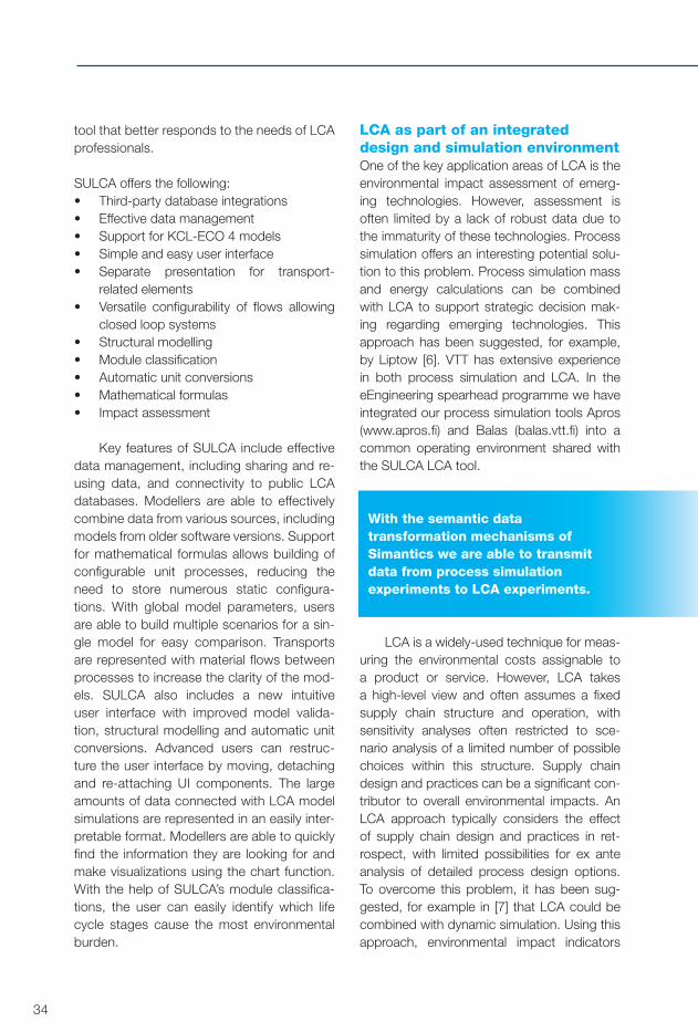
34
tool that better responds to the needs of LCA professionals.
SULCA offers the following:• Third-party database integrations • Effective data management• Support for KCL-ECO 4 models• Simple and easy user interface• Separate presentation for transport-
related elements• Versatile configurability of flows allowing
closed loop systems• Structural modelling• Module classification• Automatic unit conversions• Mathematical formulas• Impact assessment
Key features of SULCA include effective data management, including sharing and re-using data, and connectivity to public LCA databases. Modellers are able to effectively combine data from various sources, including models from older software versions. Support for mathematical formulas allows building of configurable unit processes, reducing the need to store numerous static configura-tions. With global model parameters, users are able to build multiple scenarios for a sin-gle model for easy comparison. Transports are represented with material flows between processes to increase the clarity of the mod-els. SULCA also includes a new intuitive user interface with improved model valida-tion, structural modelling and automatic unit conversions. Advanced users can restruc-ture the user interface by moving, detaching and re-attaching UI components. The large amounts of data connected with LCA model simulations are represented in an easily inter-pretable format. Modellers are able to quickly find the information they are looking for and make visualizations using the chart function. With the help of SULCA’s module classifica-tions, the user can easily identify which life cycle stages cause the most environmental burden.
LCA as part of an integrated design and simulation environmentOne of the key application areas of LCA is the environmental impact assessment of emerg-ing technologies. However, assessment is often limited by a lack of robust data due to the immaturity of these technologies. Process simulation offers an interesting potential solu-tion to this problem. Process simulation mass and energy calculations can be combined with LCA to support strategic decision mak-ing regarding emerging technologies. This approach has been suggested, for example, by Liptow [6]. VTT has extensive experience in both process simulation and LCA. In the eEngineering spearhead programme we have integrated our process simulation tools Apros (www.apros.fi) and Balas (balas.vtt.fi) into a common operating environment shared with the SULCA LCA tool.
With the semantic data transformation mechanisms of Simantics we are able to transmit data from process simulation experiments to LCA experiments.
LCA is a widely-used technique for meas-uring the environmental costs assignable to a product or service. However, LCA takes a high-level view and often assumes a fixed supply chain structure and operation, with sensitivity analyses often restricted to sce-nario analysis of a limited number of possible choices within this structure. Supply chain design and practices can be a significant con-tributor to overall environmental impacts. An LCA approach typically considers the effect of supply chain design and practices in ret-rospect, with limited possibilities for ex ante analysis of detailed process design options. To overcome this problem, it has been sug-gested, for example in [7] that LCA could be combined with dynamic simulation. Using this approach, environmental impact indicators
RH_8_eEngineering.indd 34 26.8.2013 14:50:12

35
Simantics — an open source platform for modelling and simulation
can be incorporated into a dynamic model of the supply chain along with profit and cus-tomer satisfaction, so that the sustainability of various design and operational decisions can be assessed comprehensively. VTT is utilizing system dynamics for modelling and simulation of business processes. In the eEngineering spearhead programme we have integrated our System Dynamics tool (www.simantics.org) and LCA tool SULCA into the same oper-ating environment. This will enable combined analyses in the future, as suggested above.
Towards integrated toolsetsGrowing pressure on natural resources and increased environmental awareness have created growing demand for evaluating the environmental aspects and potential environ-mental burdens of products and services. Against this background, the SULCA life cycle assessment tool, used for conducting LCA studies according to the ISO 14040:2006 and ISO 14044:2006 standards ([4] and [5]), has been developed in close collaboration with VTT’s LCA experts to respond to their needs and to enable LCA studies to be conducted with less effort and cost.
Future work includes further usability improvements based on increased user feed-back once the tool is deployed for production use. The new SULCA version is implemented in Simantics – an open-source integration platform for modelling and simulation tools. Simantics enables connectivity with a grow-ing set of other modelling and simulation tools integrated into the same environment. Future research includes exploiting the potential of co-using LCA with process simulation, busi-ness process simulation, and with system dynamics and intelligent CAD environments. For example, in process simulation an inte-grated toolset enables environmental impacts to be considered earlier in the process design. Such advanced interdisciplinary research would not be possible without the intensive collaboration of various teams and knowledge centres at VTT.
References [1] Rockström, J., Steffen, W., Noonen, K. et
al. A safe operating space for humanity.
Nature 461, pp. 472–475.
[2] Ostad-Ahmad-Ghorabi, H., Collado-Ruiz,
D. & Wimmer, W. 2009. Towards Integrating
LCA into CAD. Proceedings of ICED 09,
the 17th International Conference on Engi-
neering Design, Vol. 7, Palo Alto, CA, USA,
24.–27.08.2009.
[3] Morbidoni, A., Favi, C., Mandorli, F. & Ger-
mani, M. 2012. Environmental evaluation
from cradle to grave with Cad-integrated
LCA tools. Acta Technica Corviniensis –
Bulletin of Engineering, Tome V 2012. ISSN
2067-3809.
[4] ISO 14040:2006. Environmental manage-
ment – Life cycle assessment – Principles
and framework. CEN international stand-
ards.
[5] ISO 14044:2006. Environmental man-
agement – Life cycle assessment
– Requirements and guidelines. CEN inter-
national standards.
[6] Liptow, C. & Tillman, A. 2011. Enhancing
the data basis for LCA through process
simulation: The case of lignocellulosic eth-
anol production in Sweden, SETAC Europe
21st Annual Meeting, 2011.
[7] Nwe, E., Adhitya, A., Halim, I. & Srinivasan,
R. 2010. Green Supply Chain Design and
Operation by Integrating LCA and Dynamic
Simulation. 20th European Symposium on
Computer Aided Process Engineering –
ESCAPE20. Pierucci, s. & Buzzi Ferraris, G.
(eds.). Elsevier B.V.
Related publications Karhela, T., Villberg, A. & Niemistö, H. 2012. Open ontology-based integration platform for modeling and simulation in engineering. Inter-national Journal of Modeling, Simulation, and Scientific Computing, Vol. 3, No 2, p. 36.
Finnveden, G., Hauschild, M., Ekvall, T., Guinée, J., Heijdungs, R., Hellweg, S., Koehler, A., Pennington, D., Suh, S. 2009.
RH_8_eEngineering.indd 35 26.8.2013 14:50:12

36
Recent developments in Life Cycle Assess-ment. Journal of Environmental Management 91, pp. 1–21.
Koukkari, H.& Nors, M. (eds). 2009. Life Cycle Assessment of Products and Technolo-gies. LCA Symposium. VTT Symposium 262. VTT Technical Research Centre of Finland. Espoo. 142 p.
RH_8_eEngineering.indd 36 26.8.2013 14:50:12

37
Simantics — an open source platform for modelling and simulation
Anyone dealing with modern digital equipment is aware of the effects of inadequate software quality. Software in smartphones and set-top boxes has to be constantly updated – not to introduce new features, but simply to manage errors and issues as they emerge, to prevent them from acting up or freezing on the user. But the quality of the software of computer-based systems that are critical, for example, to the infrastructure of society, should be addressed in much more serious ways. Almost every-thing making up our infrastructure, from road and rail traffic, supply chain logistics and communication networks to power grids and plants, is controlled, or at least monitored, by software-based systems.
Although the design of industrial, criti-cal software is based on completely different practices to the software in consumer elec-tronics devices, the goal of 100% error-free software has nevertheless remained elusive. But the situation is changing.
Model checking finds hidden software errorsThe process of analysing whether a system design meets its requirements and fulfils its intended purpose is called verification and validation (V&V). For industrial instrumentation and control (I&C) systems, V&V has tradition-ally been based on testing and simulation – of either an actual system or model replicas, i.e., running the target software and benchmarking the behaviour and outcomes against sce-narios or test cases. Test runs are a valuable and necessary source of data, but testing and
Error-free software through formal methods
AUTHOR: Antti PakonenTitle: Research Scientiste-mail: [email protected]
simulation alone cannot be relied on to prove that a system is 100% error-free. Test spaces easily grow to immense proportions so that, in practice, not all possible test cases or scenar-ios can be taken into consideration. Specific, advanced test automation tools are available, but conclusive analyses are impossible due to the sheer number of possible situations that a system can, in theory, and with the necessary critical approach, be shown to incur.
Model checking is a computer-assisted formal method that can prove conclusively whether a (hardware or software) design model acts according to its stated require-ments in all situations. Both the system design and the requirements are presented in a for-mat understood by a model checking tool, called a model checker, which will then thor-oughly analyse whether a model execution that is contrary to the requirements is possi-ble. As a general principle, instead of looking at what happens in a given situation with given inputs, the idea is to define an undesired situ-ation and see if it is possible to end up there. Instead of excessively computing all com-binations, a systematic search is carried out using a graph-like model, looking only at the combinations that are relevant to each stated requirement.
Since the 90s, formal model checking has been the key verification method in micropro-cessor manufacturing, and has recently found its way into ever more versatile domains. At VTT, we have been applying model checking in the V&V of critical I&C software, i.e., the logic that controls and monitors industrial processes.
OTHER CONTRIBUTING AUTHORS: Janne Valkonen
RH_8_eEngineering.indd 37 26.8.2013 14:50:12

38
Developing practical tools for industryVersatile and mature model checking tools are available, but most are either too generic and abstract or aimed at a specific domain and, therefore, not suitable for the analysis of I&C software. So-called function blocks are one of the most common programming languages used to implement I&C sys-tems. Instead of writing code, applications are constructed by selecting predefined standard blocks (e.g., AND, OR, delay, or a PID controller) and connecting (‘wiring’) them together in a graphical diagram to obtain the desired functionality or operation logic. Each block reads its inputs, updates its internal variables, and sets its outputs according to its internal logic. Block wiring then defines the data flow and the block pro-cessing order. Function block diagrams are favoured, since (among other benefits) they present clear input-output mapping, and it is relatively easy to understand and follow the processing flow.
Accordingly, VTT has been developing tools for model checking of function block based software. Our work has been based on Simantics, an open source platform for modelling and simulation. We have been specifying a Simantics plugin for the open source model checker NuSMV, and are now able to construct the NuSMV model by wiring blocks together in a 2D graphical view.
The expected benefits of such a graphi-cal, dedicated toolset are clear. In the future, the model translation capabilities of Siman-tics are also expected to enable automatic model conversion from, for example, an existing Apros model of process control software.
Practical experience in evaluating industrial control systemsThe majority of VTT’s practical experience in applying model checking is in the nuclear industry (see Case: Nuclear on the next page) where very strict safety analysis pro-cedures are an essential requirement. The approach is, however, also more generally applicable, and we have conducted small-scale pilots in diverse I&C applications in which different programming languages and environments from different vendors have been used. Successful pilots have been per-formed, for example, in factory, power plant, electrical and machine automation projects.
The model checking approach is most suitable for the analysis of relatively straight-forward logic – the kind of logic that should be favoured for safety-critical applications – as the computational power of model checking is based on the use of fairly sim-ple modelling languages. Conversely, more sophisticated and algorithmically complex control applications, such as those needed to run a modern paper machine, for exam-ple, cannot be effectively analysed, in which case, for example, simulation-based verification and validation are more suit-able. Nevertheless, just because a system is straightforward does not mean that its analysis is simple: a binary circuit with 100 inputs and no internal memory will have 1030 different input combinations, and adding memory to the application only further com-plicates the analysis.
Solving the theoretical challengesVTT has been working with Aalto University to solve some of the theoretical challenges related to model checking and, in particular, the evaluation of I&C software. The greatest challenge is the computational effort required due to the state explosion problem: as the number of possible model states grows expo-nentially with respect to the size of the model, the analysis task can become too complex for existing methods and computers. Model
RH_8_eEngineering.indd 38 26.8.2013 14:50:12

39
Simantics — an open source platform for modelling and simulation
CASE: NUCLEAR
With new-builds and modernizations, old analogue nuclear power plant technology is being steadily replaced by digital instrumentation and control (I&C) systems. Software-based control systems can offer higher reliability, better plant performance and new diagnostic capabilities. Nevertheless, the inherent complexity of digital I&C has justifiably raised questions regarding the correctness of both hardware and software design. The industry and regulators thus face important challenges in assuring that new systems meet their requirements.
At VTT, research on model checking began in 2007 under the Finnish Research Pro-gramme on Nuclear Power Plant Safety (SAFIR2010). Successful industrial pilot cases quickly proved the value of the approach. Finnish nuclear power companies and authori-ties have shown continued interest in formal methods, and research continues under the SAFIR2014 programme.
In addition to active research, the approach has been put to practical use. VTT has been consulting the Finnish Radiation and Nuclear Safety Authority (STUK) (since 2008) and the power company Fortum on evaluating nuclear I&C systems using model checking.
RH_8_eEngineering.indd 39 26.8.2013 14:50:22

40
checking is a computationally very powerful method, but it, too, has its limits.
Specific topics for past and present research include:• Modular approach to analysis of very
large models: A technique has been developed to analyse systems that would otherwise result in models with a too large state space, based on the modular structure of the model. The model is first approximated by greatly abstracting the logic of some of the modules. An algo-rithm has been developed that iteratively searches for a composition of modules that at the same time is computation-ally manageable, and covers enough modules to prove the properties of the original model. The feasibility of the anal-ysis results for the abstracted model is then reviewed in the context of the full model.
• Analysis of asynchronous models: For many model checkers, one of the nec-essary simplifications needed in order to make the analysis efficient is that the analysed system model has a unified, discrete time cycle. However, many real-world systems are physically distributed to several different processors that each behave according to their internal clock. Model checkers that can also handle asynchronous behaviour do exist, but in these cases the size of model that can be effectively analysed is clearly smaller. A new model checking tool is being devel-oped that will combine the strengths of different types of model checkers.
• Modelling system faults: If the I&C soft-ware has a mechanism for dealing with faulty input data, the mechanism is taken into account in the model. However, if we wish to introduce failure modes of the underlying hardware architecture (‘What if one of the processors the software is running on or the communication network fails?’), extra work is needed in defining suitable failure mechanisms. We are cur-
rently working on structured approaches for doing so.
• Reliability through tool diversity: When a model checker discovers no error, there is always some question whether the design actually is error-free. Errors in the modelling process are usually found, and most often result in a ‘false negative’ result. One way of increasing confidence in the results is to use several model checkers that do not share source code in their implementation. We are currently constructing a tool portfolio that will not only enable the evaluation of more versa-tile applications than before, but also add to the reliability of analysis results.
Summary and need for further workThrough model checking, we have been able to find hidden design errors in software systems that have already undergone verifi-cation and validation through more traditional means. Others have reported similar results in diverse application areas, such as aviation. The method is not, however, a one-size-fits-all solution, since it is only effective for the evaluation of fairly straightforward software applications (which safety-critical industrial control systems often are). Also, expert knowl-edge is always needed when applying formal methods.
VTT is currently working on the theoreti-cal challenges as well as more practical issues related to the application of model checking in industrial contexts. The Simantics plat-form enables us to bring model checking to the mainstream, as the dedicated, user-friendly tool makes it possible to implement model checking with less knowledge of the underlying theory. Our current tool devel-opment approach is tied to function block diagrams as the programming language of I&C software, but other viewpoints are also needed, as, for example, the C language is often used in the industry, and model check-ers for verifying C code are also available. On
RH_8_eEngineering.indd 40 26.8.2013 14:50:22

41
Simantics — an open source platform for modelling and simulation
the theoretical side, new methods are needed to handle the specification of system require-ments. Our ongoing research is nevertheless motivated by successful applications both in research pilot cases and in practical customer projects.
To date, practical application of VTT’s model checking has been mainly within the context of nuclear power plants, as the nuclear industry is subject to rigorous legis-lative requirements regarding safety analysis. However, safety is not the only criterion driv-ing strict V&V – cost is also an important factor. While the expertise needed for model checking does not come free of charge, the expenses caused by the downtime of indus-trial plants or infrastructure systems due to design faults can be immense.
Related publications Lahtinen, J., Valkonen, J., Björkman, K., Frits, J. & Niemelä, I. 2012. Model checking of safety-critical software in the nuclear engi-neering domain. Reliability Engineering and System Safety, Vol. 105, pp. 104–113.
Pakonen, A., Mätäsniemi, T. & Valkonen, J. 2012. Model Checking Reveals Hidden Errors in Safety-Critical I&C Software. 8th International Topical Meeting on Nuclear Plant Instrumentation, Control, and Human-Machine Interface Technologies (NPIC & HMIT 2012). San Diego, California, USA, 22–26 July 2012. American Nuclear Society. Pp. 1823–1834. ISBN 978-0-9448-093-0.
Lahtinen, J., Launiainen, T., Heljanko, K. & Ropponen, J. 2012. Model Checking Methodology for Large Systems, Faults and Asynchronous Behaviour. Espoo: VTT. 84 p. (VTT Technology 12.) ISBN 978-951-38-7625-8. http://www.vtt.fi/inf/pdf/technology/2012/T12.pdf.
Lahtinen, J., Valkonen, J., Björkman, K., Frits, J. & Niemelä, I. 2010. Model check-ing methodology for supporting safety critical
software development and verification. Euro-pean Safety and Reliability Conference (ESREL2010). Rhodes, Greece, 5–9 Sept 2010. Ale, B.J.M., Papazoglou, I.A., Zio, E. (Eds). Reliability, Risk and Safety – Back to the Future. European Safety and Reliability Association (ESRA). Pp. 2056–2063. ISBN 978-0-415-60427-7.
Valkonen, J., Björkman, K., Frits, J. & Nie-melä, I. 2010. Model checking methodology for verification of safety logics, The 6th Inter-national Conference on Safety of Industrial Automated Systems (SIAS 2010), Tampere, Finland, 14–15 June 2010. http://www.vtt.fi/inf/julkaisut/muut/2010/SIAS_final.pdf.
RH_8_eEngineering.indd 41 26.8.2013 14:50:22

42
Authors
Susanna Aromaa Marko Antila Research Scientist Senior Scientist
Eero Kokkonen Boris Krassi Simo-Pekka LeinoSenior Scientist Senior Scientist Senior Scientist
Hannu Nykänen Kaj Helin Sauli KivirantaPrincipal Scientist Principal Scientist Research Scientist
RH_8_eEngineering.indd 42 26.8.2013 14:50:45

43
Designing user experience for the machine cabin of the future
RH_8_eEngineering.indd 43 26.8.2013 14:50:45

44
RH_8_eEngineering.indd 44 26.8.2013 14:50:45

45
Designing user experience for the machine cabin of the future
In addition to safety, operator comfort has become an essential driver of product design and development in the mobile machine industry. Typically, the machine cabin designer focuses on one or, at most, a few proper-ties at a time, such as physical ergonomics or machine feasibility during task execution. However, user experience (UX) and comfort are a combination of several different fea-tures. A holistic UX and comfort evaluation includes aspects such as psychoacous-
Designing user experience for the machine cabin of the future
AUTHOR: Susanna AromaaTitle: Research Scientiste-mail: [email protected]
tics, thermal comfort, vibrations within the cabin, musculoskeletal discomfort, and visibility from the cabin. For many of these factors, UX vary greatly between individuals, tasks and working environments. New tools and methods are therefore needed to iden-tify and optimize these factors to meet user requirements in design and to evaluate their feasibility in practice.
But how to evaluate human–machine interaction parameters and their combined
Figure 1. The multidisciplinary design environment enables designers to take key factors affecting user experience and comfort into early consideration in the design process.
OTHER CONTRIBUTING AUTHORS: Marko Antila, Eero Kokkonen, Boris Krassi, Simo-Pekka Leino, Hannu Nykänen, Kaj Helin, Sauli Kiviranta
Integration
Air conditioning modelling
User experienceevaluation
Virtualenvironment
Acousticmodelling
Design Environmet for User Experience
RH_8_eEngineering.indd 45 26.8.2013 14:50:49

46
effect on the UX in the early design phase, when physical prototypes are too costly to construct or not available? This can be achieved by using Virtual Environments (VEs), which com-bine design models and operation simulations to enhance the natural feel of a simulated work task, when evaluating a design. With VEs that include a good visualization system, realistic motion platform, realistic acous-tics, and air conditioning modelling, it is possible to assess the combined effect of these parameters, thus benefitting the user through improved design with respect to comfort, ergonomics, usability and safety. In addition, machine manufacturing com-panies also benefit through reduced design costs, faster time-to-market, and better prod-uct quality, as requirements can be evaluated early and modifications can be made fast.
Virtual design environment enables holistic consideration of the user The main outcome of this sub-project of the eEngineering programme was the develop-
ment of a virtual, simulator-based design environment for the multidisciplinary UX design of machine cabins. The project had two main objectives: (1) Integration of vari-ous areas or systems, such as, acoustic modelling, air condition modelling, and UX evaluation into one design environment (such as VEs), see Figure 1. (2) Development of UX and comfort evaluation methods (psy-choacoustics, thermal comfort, whole-body vibration, musculoskeletal discomfort and operator’s field of view) to enable more holis-tic UX evaluation.
Holistic user consideration changes the entire product design and development process Impacts on product processes were also studied during the project, with a focus on how use of the novel virtual design environ-ment changes current product design and development processes, and how to bring the environment into normal practice within indus-try. Product or system design life cycles – from
Figure 2. Impacts of the multidisciplinary design environment on virtual and physical product life. The left side illustrates the phases of the design process. The use of VE smooths the iterations and phases and eases communication across phases. The right side shows the effect of VE on time-to-market due to earlier and more effective require-ments validation and verification and thus fewer engineering changes and interruptions.
RH_8_eEngineering.indd 46 26.8.2013 14:50:57
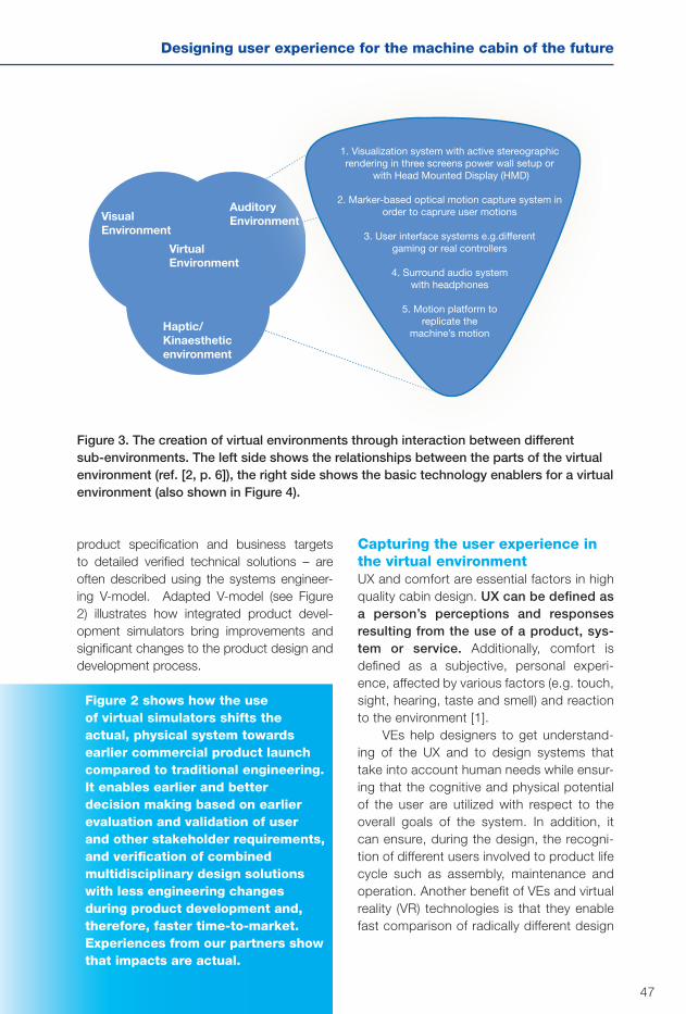
47
Designing user experience for the machine cabin of the future
product specification and business targets to detailed verified technical solutions – are often described using the systems engineer-ing V-model. Adapted V-model (see Figure 2) illustrates how integrated product devel-opment simulators bring improvements and significant changes to the product design and development process.
Figure 2 shows how the use of virtual simulators shifts the actual, physical system towards earlier commercial product launch compared to traditional engineering. It enables earlier and better decision making based on earlier evaluation and validation of user and other stakeholder requirements, and verification of combined multidisciplinary design solutions with less engineering changes during product development and, therefore, faster time-to-market. Experiences from our partners show that impacts are actual.
Capturing the user experience in the virtual environment UX and comfort are essential factors in high quality cabin design. UX can be defined as a person’s perceptions and responses resulting from the use of a product, sys-tem or service. Additionally, comfort is defined as a subjective, personal experi-ence, affected by various factors (e.g. touch, sight, hearing, taste and smell) and reaction to the environment [1].
VEs help designers to get understand-ing of the UX and to design systems that take into account human needs while ensur-ing that the cognitive and physical potential of the user are utilized with respect to the overall goals of the system. In addition, it can ensure, during the design, the recogni-tion of different users involved to product life cycle such as assembly, maintenance and operation. Another benefit of VEs and virtual reality (VR) technologies is that they enable fast comparison of radically different design
Figure 3. The creation of virtual environments through interaction between different sub-environments. The left side shows the relationships between the parts of the virtual environment (ref. [2, p. 6]), the right side shows the basic technology enablers for a virtual environment (also shown in Figure 4).
VisualEnvironment
AuditoryEnvironment
VirtualEnvironment
Haptic/Kinaestheticenvironment
1. Visualization system with active stereographic rendering in three screens power wall setup or
with Head Mounted Display (HMD)
2. Marker-based optical motion capture system in order to caprure user motions
3. User interface systems e.g.different gaming or real controllers
4. Surround audio systemwith headphones
5. Motion platform toreplicate the
machine’s motion
RH_8_eEngineering.indd 47 26.8.2013 14:50:58

48
solutions without the need for physical pro-totypes.
The main quality criteria for VEs have tra-ditionally been the quality of 3D graphics and the generation speed and smoothness of visu-alization. High quality visuals are undoubtedly the single most important factor when aiming to create an effective and functional VEs. How-ever, 3D graphics alone are not sufficient to produce a realistic illusion of an environment. In addition to vision, manipulation of the other senses is also required to create a convinc-ing illusion of reality, i.e., VR. The key senses include hearing, haptic (touch) and kinaes-thetic (body position and movement) senses, and to a lesser degree, taste and smell.
Figure 3 [ref. 2, p. 6], depicts how a VE consists of several simultaneously interacting
Figure 4. The virtual environment developed at VTT consists of five subsystems: (1) Main visualization system with active stereographic rendering in three walls setup plus sec-ondary visualization system with head-mounted display (HMD); (2) Marker-based optical motion capture system to capture user motions; (3) User interface (UI) system combining different gaming controllers and basic keyboard interaction; (4) Ambient audio system with headphones; and (5) Motion platform to replicate machine motion.
sub-environments. The visual, auditory, and haptic environments together form the VE. If any of these is missing, the VE is consid-erably less functional and realistic. The VE created at VTT and its subsystems are illus-trated in Figure 4.
Development of the UX and comfort evaluation methods was started by selecting key cabin design parameters, such as: psy-choacoustics, thermal comfort, whole-body vibration, musculoskeletal discomfort and operator’s field of view.
Psychoacoustic Experience Evaluation and Enhancement (PEEE) is a method for evaluating how human beings experience the acoustic environment and for improving key factors of the acoustic experience. Real or modelled sound events in a real or modelled
(2)
(1)
(3)
(5)
(4)
RH_8_eEngineering.indd 48 26.8.2013 14:51:10

49
Designing user experience for the machine cabin of the future
acoustic environment are captured or gen-erated in binaural form. Binaural signals are then used in listening tests or for extraction of individual psychoacoustic metrics, such as loudness and sharpness.
UX of thermal comfort is evaluated by applying Fanger’s thermal comfort model [3, 4]. Additionally, window fogging and dust dis-persion can be simulated. Air flows and other cabin air conditioning related phenomena can then be visualized in VEs enabling users to visually experience air flow streams, thermal comfort, window fogging and dust dispersion.
In order to measure the whole-body vibra-tion dose experienced by the user, data based on standard acceleration is gathered from the motion platform or by collecting acceleration sensor data from the seat. The vibration dose is calculated based on standard ISO 2631-1 [5].
Subjective musculoskeletal symptoms of the user are collected via a computer-aided tool that enables the user to choose a body part from a body map and then indicate their
severity of discomfort. Data on experienced musculoskeletal discomfort and degree of discomfort is gathered before and after per-forming the task in the VEs.
To increase the use of real operators in field of view (FOV) evaluations, a new method for calculating FOV in VEs was developed. The FOV analysis method is based on task-related visibility and occlusion evaluation of target objects in the operator’s FOV. The method calculates (1) the percentage of vis-ible target object pixels from all pixels in the operator’s FOV, and (2) the percentage of occluded (by the cabin structure) pixels from the visible target object pixels in the opera-tor’s FOV. The results facilitate comparison of the impacts of alternative design solutions on visibility.
Auralization: the virtual hearing experience Effective audio is key to building a convinc-ing VR experience. In VEs, sound events and acoustics are simulated to sufficient accu-
Figure 5. Modular sound generation for virtual reality. Position tracking follows the posi-tion and movements of objects (including the observer) in the VE. A dynamics solver creates the dynamic parameters for the model. This information is forwarded to the VR software, which translates them into an appropriate format for the sound creation block. Sound from the sound creation block is localized by the sound localization block, and then sent either to the headphones or loudspeakers.
POSITIONTRACKING
DYNAMICSSOLVER
VIRTUALREALITY
SOFTWARE
Audio Sub-system
Soundcreation
Soundlocalization
5.1Loud-
speakers
Head-phones
RH_8_eEngineering.indd 49 26.8.2013 14:51:11

50
racy to create an immersive experience while not placing excessive demands on system resources. The most important requirement is real-time and concurrent operation of the audio simulator and visualization to preserve the illusion of immersion. Visualization events must be tightly synchronized with the aural-ized environment.
In general, sound events and acoustics form an audio sub-system itself, as illustrated in Figure 5. Sound events are generated in the Sound Creation block and are positioned accordingly in the Sound Localization block. A 5.1 loudspeaker setup comprising 3 loud-speakers in the front (left, right, and middle), 2 rear loudspeakers and a subwoofer, was used as the main sound source. Panned sound within these loudspeakers can also be converted to headphone use. Sound panning involves projecting sound in a certain direction by changing the level of sound in each indi-vidual loudspeaker. The audio subsystem gets its parameters in real time from the VR soft-ware, which generates the parameters based
on position tracking and information from a dynamics solver.
Sounds can be created in the VEs in various ways. In many industries the common practice is simply to pre-record or sample noise signals and then play them back in the VEs. At the other end of the spectrum, audi-ble models are being developed to generate sound and noise based on parameters such as tonal component levels, frequencies, relative phases, broadband noise frequency content, and level of amplitude modulation. Such audio models offer the potential to create truly vir-tual audio experiences and are therefore a key focus area of current research.
The Audible Model Platform (AMP) developed by VTT is a parameter-based sound and noise generation platform. The AMP is not directly based on the structural or mechanical physics of noise generating machinery, but rather the noise profile parameters are functions of angular velocity (rpm), load, listening position and other relevant factors.
Figure 6. Audible Model Platform (AMP) tailored for the cabin noise model. The sources of noise are engine orders, hydraulics orders, engine broadband noise and ventilation noise. All of these are affected by various parameters coming from external VE source.
Enable Sub-system
3DHead-phones
Soundlocalization
Engineorders
Auxperiodicsources
(hydraulicsturbo ect.)
Enginebroadband
Orderscaling
Orderscaling
VENTILATIONNOISE
RPM/LOAD/OTHER
PARAMETERSSOURCE
5.1Loud-
speakers
RH_8_eEngineering.indd 50 26.8.2013 14:51:12

51
Designing user experience for the machine cabin of the future
The AMP is used here for cabin noise modelling, but it has also been customized for various fixed engine applications and even outdoor noise applications, most recently for noise modelling of wind turbines. AMP noise profile parameters include engine and other rotating mechanical system acoustical order structure, levels and phases, as well as, similar parameters for auxiliary mechanical systems, such as cooling, turbo and hydraulics. Fur-thermore, broadband noise is parameterized whenever applicable, and otherwise modelled based on a steady-state empirical model. Due to the parameter-based design, changes in parameters also cause real-time changes in the rendered audio.
The noise profile parameters can be extracted from the measurements or noise recordings. For this extraction, automatic and semi-automatic tools have been generated. Parameters from the numerical models can also be used if they can be generated. The AMP also visualizes engine orders and gen-erated noise, and the visualization parameters can also be sent back to the VE. Each order contribution is visualized in real time, as well as the overall noise spectrum. Individual nar-
rowband or broadband components can be turned on and off to evaluate their noise con-tribution.
An example AMP for cabin noise genera-tion is presented in Figure 6. Here, the main sources of noise are engine orders, hydraulics orders, engine broadband noise and ventila-tion noise. All of these are affected by various parameters coming from external VE source, such as dynamics solver. The noise level and sound quality parameters are also calculated and are available in the model or as outputs to VR software.
Air conditioning in a virtual cabin – more than just temperature control Detailed information on air flows and other cabin air conditioning related phenomena can be obtained using computational fluid dynamics (CFD). For example, air flow pat-terns, thermal comfort, window fogging and dust dispersion inside the cabin can be determined computationally without a physical model of the cabin, as dem-onstrated in Figure 7. The cabin geometry and details such as the location of supply air inlets can be varied and the effects of the
Figure 7. Computational fluid dynamics (CFD) simulation can be executed at the very beginning of the product development cycle to provide detailed information on air con-ditioning properties from the user’s perspective even if no physical models of the cabin exist. The resulting air flows, thermal comfort, window fogging and hazardous silica dust dispersion to breathing zone of the operator can all be visualized in 3D.
RH_8_eEngineering.indd 51 26.8.2013 14:51:17

52
changes can be estimated. All of this can be carried out at the very beginning of product development, providing much more detailed knowledge of the system compared to what physical models alone would provide.
The UX related to air conditioning is highly dependent on cabin airflow patterns, which in turn are dependent on, for example, the geometry of the cabin. Detailed data on the steady-state flow field (i.e. velocity, pres-sure, temperature, etc., values in each spatial location) are obtained from the CFD calcula-tion. In the standard procedure of CFD, the domain of interest, here a work machine
cabin, is divided into a grid of small com-putation or control volumes over which the Navier–Stokes equations are solved numeri-cally, resulting in 3D data for the flow field. The thermal comfort of the operator can be evalu-ated by applying this CFD data to Fanger’s thermal comfort model. Thermal comfort is determined based on six parameters: air temperature, air velocity, mean radiant tem-perature, relative humidity, metabolic activity level and clothing of the human. The comfort indices are widely used and have reached the status of normative reference (ISO 7730). The classical comfort indices are suitable
Figure 8. The result of an air conditioning simulation comprising the evaluation of thermal comfort, window fogging and dust dispersion from floor by air flows. The experienced thermal environment (average over a group of people) is represented by PMV (predicted mean vote) ranging from cold (-3) via neutral (0) to hot (+3). Humidity originating from the operator, wet floor and supply air inlets, dispersed and condensated on the windows, is visualized by the variable filmMass (kg/m²/s). The dust concentration dispersion from the floor is visualized by constant concentration contours. Instead of analysing absolute concentration values, the resulting concentration values are normed to the uniformly dispersed concentration; for example, a scaled concentration of dust scaled = 1 corre-sponds to the dust concentration if it would be uniformly mixed throughout the whole air volume of the cabin.
RH_8_eEngineering.indd 52 26.8.2013 14:51:19

53
Designing user experience for the machine cabin of the future
for representing conditions in an enclosed space provided that fairly uniform conditions hold. However, the airflow in a cabin envi-ronment does not satisfy the assumptions of uniform conditions. Contrary to Fanger’s original method, heat exchange is modelled by CFD methods and the actual flow proper-ties provided by the CFD calculation are used to determine the comfort indices. In addi-tion, fogging of the cabin windows can be modelled by solving the dispersion of water vapour inside the cabin and by solving the condensation onto the window surface. Fur-thermore, the transport of hazardous silica dust into the breathing zone of the operator can be modelled by solving the dispersion of dust from the floor due to air flows. In some cases, such as an underground loader, the cabin floor can become covered with sand containing hazardous quartz (SiO2) dust particles. An example of air conditioning sim-ulation is shown in Figure 8.
Empowering manual work with augmented realityAccording to Eurostat [6], in 2012 15.7 mil-lion people1 were involved in high-knowledge manual work in Europe, mainly as plant and machine assemblers and operators. Numer-ous industry sectors depend on the knowledge and skills – such as satellite assembly, nuclear reactor maintenance, operation of complex machinery, design and manufacturing of highly customized products – of their manual work-ers. In these sectors, manual work constitutes the core operations and cannot be off-shored or easily automated.
The EU-funded ManuVAR project coordinated by VTT [7, 8] developed a new system with the potential to significantly improve productivity and working environ-ments across Europe. The project combined product life cycle management, ergonomics, and virtual and augmented reality (VR and AR) technology.
The following four main results were achieved by the project.
1. Most prominent problem areas faced by European industries in the context of high knowledge high value manual work:* Hindered communication across vari-
ous actors throughout the life cycle.* Poor interfaces with complex CAD
and information systems.* Inflexible design processes – feedback
from later life cycle stages is difficult to utilize in design improvement.
* Inefficient knowledge management – substantial employee know-how not utilized in system design and improve-ments.
* Low productivity of manual work due to poor overall system design.
* Lack of acceptance of supporting technologies, especially virtual and augmented reality technologies, in industrial contexts.
* Physical and cognitive stress of man-ual workers, could be minimized by a better system design.
2. Five industrial cluster cases including performance criteria for the evaluation of laboratory trials and factory-floor dem-onstrations, business analysis, economic impact forecast, training and technology transfer plans:* Cluster 1: Support of Spacecraft
Assembly. Develop and validate criti-cal procedures in VR that can be used to support integration assembly activi-ties through AR instructions.
* Cluster 2: Manufacturing design for SMEs. Support assembly line workers by means of an automatic work load evaluation tool and reduce learning time by means of an operator naviga-tion tool.
* Cluster 3: Remote support in train maintenance. Support the main-tenance of complex systems by exploiting the benefits of AR technol-ogy and reinforcing communication between actors involved.
1 Total obtained for EU27 countries from the referred table “Employment by sex, age, professional status and accupation” as of 04-07-2013, by selecting industry category (ISCO) “Plant and machine operators, and assemblers”, data for 2012.
RH_8_eEngineering.indd 53 26.8.2013 14:51:19

54
* Cluster 4: Training for industrial plant maintenance. Training for metallo-graphic replica activities using VR with visual, audio and haptic interaction.
* Cluster 5: Design and maintenance of heavy machinery. Assembly and maintenance design reviews and instructions.
3. System architecture characterized by the following features [9]:* Bi-directional communication
throughout the system life cycle (e.g. worker feedback to designers, designer recommendations to work-ers) is accomplished by means of a
‘virtual model’. The virtual model plays the role of communication media-tor – a single systemic access point to a variety of system data, informa-tion and models for all users in the life cycle – accessed as an integral sys-tem by ‘virtual experiments’;
* Adaptive VR/AR user interfaces to the complex virtual model, suitable for all actors in the life cycle: from workers to engineers to managers. The VR/AR interfaces are implemented by com-ponent reconfiguration with low-delay middleware (haptics, tracking, VR/AR
Contextual instruction delivery: AR, tracking; remote and local versions
Figure 9. ManuVAR application tools. Source: ManuVAR consortium.
Ergonomics evaluation: automatic physical and cog-nitive load analysis, full body motion capture
Task analysis and procedure validation: hierar-chical task analysis, VR with haptics
Motor skill training: VR with haptics, precision teaching theory
RH_8_eEngineering.indd 54 26.8.2013 14:51:27

55
Designing user experience for the machine cabin of the future
visualization, application logic, con-nection to PLM systems);
* Four groups of ergonomics meth-ods covering the principal ways of improving manual work from the system-cybernetics perspective: workplace design, ergonomics evalu-ation, instruction delivery, and training;
* Knowledge management concept based on Nonaka’s organizational knowledge creation theory, with each modality of knowledge creation supported: externalization and inter-nalization (adaptive and natural user interfaces with VR/AR), socialization (bi-directional communication and the virtual model), and combination (linking in the virtual model and con-nection to PLM systems).
4. Four reconfigurable application tools, which can be combined together via the virtual model to solve a given industrial case, were designed, implemented and evaluated in the laboratory and in the company environment, Figure 9.
The ManuVAR system was demon-strated in all five project clusters. Around 110 workers, engineers, managers and custom-ers from 23 external companies were also included in the project. The feedback was constructive and indicated considerable interest from the industry:• ‘I think training could be performed in
less time, reducing the “in-class” training of trainers, and so be much more effi-cient with ManuVAR’.
• ‘Operators will be more open to record-ing and analysing their postures and movements. Giving immediate results and feedback will probably encour-age them to change their postures and movements’.
• ‘Connection to the company PDM would make it possible to use simulations and modify data models using an innovative
recursive process rather than the normal waterfall approach’.
Towards user experience designThe multidisciplinary UX based approach to cabin design implemented in the eEngineering programme appears, based on the first ver-sion integration alone, to be highly promising. The results also appear generalizable to the transportation and manufacturing industries. In the future, finding ways for reliable evalua-tion of comfort continues to be challenging as well as overcoming technical constraints of vir-tual reality systems that may limit the realistic user experience. Nevertheless, the presented approach to cabin design is very beneficial due to its holistic approach to these complex socio-technical systems.
References [1] De Looze, M.P., Kuijt-Evers, L.F.M. & Van
Dieën, J.H. 2003. Sitting comfort and
discomfort and the relationships with
objective measures. Ergonomics, Vol. 46,
pp. 985–997.
[2] Kalawsky, R. S. 1993. The Science of
Virtual Reality and Virtual Environments.
Addison-Wesley.
[3] Fanger, P. 1967. Calculation of thermal
comfort: introduction of a basic comfort
equation, ASHRAE Trans., 73, III.4.1–
III.4.20.
[4] Fanger, P. 1970. Thermal comfort, Copen-
hagen, Danish Technical Press.
[5] ISO 2631-1. 1997. Mechanical Vibration
and Shock – Evaluation of Human Expo-
sure to Whole–Body Vibration. Part 1:
General Requirements. Geneva.
[6] Eurostat: http://appsso.eurostat.
ec.europa.eu/nui/show.do?dataset=lfsa_
egais&lang=en
[7] ManuVAR web site: www.manuvar.eu
(accessed August 6, 2013)
[8] Krassi, B. 2012. Manual work support
throughout the system life cycle by
exploiting Virtual and Augmented Reality
(ManuVAR). In ‘Production matters: VTT in
RH_8_eEngineering.indd 55 26.8.2013 14:51:27

56
global trends’. Häkkinen, K. (ed.). Espoo:
VTT. Pp. 84–88, ISBN 978-951-38-7860-3.
www.vtt.fi/inf/pdf/researchhighlights/2012/
R3.pdf
[9] Krassi, B., Kiviranta, S., Liston, P., Leino,
S.-P., Strauchmann, M., Reyes-Lecuona,
A., Viitaniemi, J., Sääski, J., Aromaa, S.,
Helin, K. 2010. ManuVAR PLM model,
methodology, architecture, and tools for
manual work support throughout system
lifecycle. Proceedings of the 3rd Inter-
national Conference on Applied Human
Factors and Ergonomics (AHFE2010),
Miami, Florida, USA.ISBN-13: 978-0-
9796435-4-5.
Related publications Aromaa, S., Leino, S.-P., Viitaniemi, J., Jokinen, L. & Kiviranta, S. 2012. Benefits of the use of Virtual Environments in product design review meeting. International Design Conference, Dubrovnik, Croatia, May 2012, 21–24. 8 p.
Aromaa, S., Leino, S.-P., Kiviranta, S., Krassi, B. & Viitaniemi, J. 2012. Human-machine system design: the integrated use of human factors, virtual environments and product lifecycle management. Tijdschrift voor Ergonomie, Vol. 37, No. 3, pp. 11–16.http://www.vtt.fi/inf/julkaisut/muut/2012/Human-machine_system_design.pdf
Viitaniemi, J., Aromaa, S., Leino, S.-P., Kiviranta, S. & Helin, K. 2010. Integration of User-Centred Design and Product Develop-ment Process within a Virtual Environment. Practical case KVALIVE. Espoo, VTT. 39 p. VTT Working Papers; 147. ISBN 978-951-38-7489-6.http://www.vtt.fi/inf/pdf/workingpapers/2010/W147.pdf
RH_8_eEngineering.indd 56 26.8.2013 14:51:27

57
RH_8_eEngineering.indd 57 26.8.2013 14:51:27

58
Impacts of eEngineering 2009—2012
Inputs • The volume of the programme EUR 31 million, approximately 250 person years.o The annual budget varied between EUR 7-9 million.
• The programme consisted of ca. 130 projects:o 43 contract research projects, with total revenue of 6,1 M€.o 63 public and jointly funded projects, totalling 18,4 M€ (13,6 M€ external
funding and 4,8 M€ VTT’s own funding).o 15 of the joint projects were funded by EU (with EU revenue 3,7 M€).o 11 of the joint projects were carried out in the context with SHOK’s
(Strategic Centres for Science, Technology and Innovation) and 9 pro-jects in the context with SAFIR (Finnish public research programme on nuclear power plant safety), while others were funded directly by Tekes or Academy of Finland.
o 30 projects self-funded by VTT with total revenue of 6,7 M€.o Included in the above figures, there were three multi-million project clus-
ters of several industrial and university partners, each contributing with their own resources.
Out-puts
• Several successful technology transfer actions, for example,o 87 licensing agreements involving simultaneous process development
with the cliento Contracts with 5 big industrial customers, reflecting the commercial rel-
evance of programme themeso Formation of 2 alliances of private and public partners
• 5 invention disclosures• 1 start-up company (Semantum)• Altogether ca. 40 technical and scientific (10) publications, including peer
reviewed scientific journals, international conference papers, and VTT pub-lications.
• Development and release of the SIMANTICS platform, an ontology based integration environment for modelling and simulation, that enables the linking and co-use of models of different levels of details through different viewpoints to the models and transformations between engineering (CAD) information and simulation models.
• Simantics Constraint Language (SCL) for transformations between engi-neering and simulation components’ data models within SIMANTICS.
• Development and release of several other simulation and engineering tools • 2011 Automation award of the Finnish Automation Society to VTT’s Siman-
tics team• 2010 VTT Award to Research Professor Tommi Karhela for outstanding
work on the Simantics platform
RH_8_eEngineering.indd 58 26.8.2013 14:51:27

59
High-lighted exam-ples
In terms of the SIMANTICS platform:• New release of VTT’s Apros ver. 6 (software for modelling and dynamic
simulation of processes and power plants) built on top of SIMANTICS 1.6.• Integration between the Siemens Comos engineering system and the
Apros simulator via SIMANTICS. • Integration of the Intergraph SmartPlant design system and the Apros
simulator. • Integration between an automation CAD program and the Apros simulator.• Integration of modelling and simulation capabilities utilising Modelica
simulation language, especially for mechanical engineering purposes, to SIMANTICS.
• Design and implementation of a multibody system (MBS) modelling and simulation environment demonstrator. The demonstrator utilises brings together the 3D geometry modelling and visualisation capabilities of CAD software and the OpenModelica language.
• Integration of a best in class life-cycle analysis (LCA) software, KCL-Eco, to SIMANTICS. Due Thanks to SIMANTICS, additional capabilities are enabled, e.g., connections to process simulators, interfaces to industrial design systems and databases, possibility to use user-interfaces of other engineering tools, and multi-user support.
In terms of virtual design environment:• Integration of model checking to SIMANTICS. A more efficient and reliable
model checking enabled together with ability to verify the correctness of larger systems than before.
• Implementation of the whole design chain of mobile machine cabins in comprehensive virtual environment; regarding visual appearance, thermal conditions, and sound or vibration experiences.
• Modelling, simulation and control of the entire exhaust tube of a combus-tion-engine as a noise or vibration source, in all audible frequencies to manage better the noise properties and user experience.
People & net-works
• The most significant industrial partners in the programme have been For-tum, Wärtsilä, and Metso. In joint projects the sphere of partners consists of dozens of firms.
• The open source SIMANTICS platform is today hosted by Simantics Divi-sion of the THTH Association of Decentralized Information Management for Industry with 25 industrial and academic members .
• Linkoping University and Modelica Association (Simantics, mechanical engineering)
• Royal Institute of Technology (machine modelling)• Luleå University of Technology (automation, Artemis activities, ProcessIT.
EU –strategy)• Steering Group of the programme: Rauno Heinonen, Risto Kuivanen, Tuomo
Niskanen• Core team of the programme: Olli Ventä (programme manager), Ismo Ves-
sonen, Riikka Virkkunen, Tommi Karhela, Timo Määttä, Teijo Salmi
RH_8_eEngineering.indd 59 26.8.2013 14:51:27

RH_8_eEngineering.indd 60 26.8.2013 14:51:27

Title eEngineering 2009—2012. Digitising the product process
Author(s) Kaisa Belloni and Olli Ventä (Eds.)
Abstract In addition to industrial production, the success of Finnish industry is based strongly on the design and engineering of devices, working machines, manufacturing plants, power plants, process machinery and ships for global markets. At the same time, digitisation has become ever more vital to the success of industrial production and engineering and the volume, value and importance of the digital, virtual realm is increasing dramatically compared to physical plants and machines.
At the beginning of the 2010s traditional heavy industry accounted for 75% of the total value of Finnish exports, up notably from 57% in 2000. To reduce the design and production ramp-up times by half, VTT’s eEngineering spearhead programme (2009-2012) developed technology platforms for modelling and simulation, design knowledge management, life-cycle management, and human-technology interaction. The high-lights of the research carried out during the programme are presented in this publication.
The most significant achievement of the programme is Simantics, an extensive operating system providing an open, high-level application platform on which different computational tools can be easily integrated to form a common environment for modelling and simulation. Programme also enabled successful integration of user’s sound and noise experience and thermal comfort modelling to the design of machine cabins in a vir-tual design environment.
ISBN, ISSN ISBN 978-951-38-8125-2 (print)ISBN 978-951-38-8126-9 (online)ISSN-L 2242-1173ISSN 2242-1173 (print)ISSN 2242-1181 (online)
Date 2013
Language English
Pages 59 p.
Keywords System modelling, simulation platform, model integration, user experi-ence design, machine cabin, auralization, virtual simulation environ-ment
Publisher VTT Technical Research Centre of FinlandP.O. Box 1000 FI-02044 VTT, Finland Tel. +358 20 722 111
Series title and numberVTT Research Highlights 8
RH_8_eEngineering.indd 61 26.8.2013 14:51:28

VTT Technical Research Centre of Finland is a globally networked multitechnological contract research organization. VTT provides high-end technology solutions, research and innovation services. We enhance our customers’ competitiveness, thereby creating prerequisites for society’s sustainable development, employment, and wellbeing.
Turnover: EUR 300 million Personnel: 3,200
VTT publications
VTT employees publish their research results in Finnish and foreign scientific journals, trade periodicals and publication series, in books, in conference papers, in patents and in VTT’s own publication series. The VTT publication series are VTT Visions, VTT Science, VTT Technology and VTT Research Highlights. About 100 high-quality scientific and profes-sional publications are released in these series each year. All the publications are released in electronic format and most of them also in print.
VTT VisionsThis series contains future visions and foresights on technological, societal and business topics that VTT considers important. It is aimed primarily at decision-makers and experts in companies and in public administration.
VTT ScienceThis series showcases VTT’s scientific expertise and features doctoral dissertations and other peer-reviewed publications. It is aimed primarily at researchers and the scientific community.
VTT TechnologyThis series features the outcomes of public research projects, technology and market reviews, literature reviews, manuals and papers from conferences organised by VTT. It is aimed at professionals, developers and practical users.
VTT Research HighlightsThis series presents summaries of recent research results, solutions and impacts in selected VTT research areas. Its target group consists of customers, decision-makers and collaborators.

eEngineering 2009—2012
In addition to industrial production, the success of Finnish industry is based strongly on the design and engineering of devices, working machines, manufacturing plants, power plants, process machinery and ships for global markets. At the same time, digitisation has become ever more vital to the success of industrial production and engineering and the volume, value and importance of the digital, virtual realm is increasing dramatically compared to physical plants and machines.
At the beginning of the 2010s traditional heavy industry accounted for 75% of the total value of Finnish exports, up notably from 57% in 2000. To reduce the design and production ramp-up times by half, VTT’s eEngineering spearhead programme (2009—2012) developed technology platforms for modelling and simulation, design knowledge management, life-cycle management, and human-technology interaction. The highlights of the research carried out during the programme are presented in this publication.
The most significant achievement of the programme is Simantics, an extensive operating system providing an open, high-level application platform on which different computational tools can be easily integrated to form a common envi-ronment for modelling and simulation. Programme also enabled successful integration of user’s sound and noise experience and thermal comfort modelling to design of machine cabins in a virtual the design environment.
ISBN 978-951-38-8125-2 (print)ISBN 978-951-38-8126-9 (online)ISSN-L 2242-1173ISSN 2242-1173 (print)ISSN 2242-1181 (online)
VT
T R
ES
EA
RC
H H
IGH
LIG
HT
S 8
eEngineering 2009—
2012