value-centric design architecture based on analysis of
TRANSCRIPT
The University of Manchester Research
Value-Centric Design Architecture Based on Analysis ofSpace System CharacteristicsDOI:10.1016/j.actaastro.2017.12.017
Document VersionAccepted author manuscript
Link to publication record in Manchester Research Explorer
Citation for published version (APA):Xu, Q., Hollingsworth, P., & Smith, K. (2018). Value-Centric Design Architecture Based on Analysis of SpaceSystem Characteristics. Acta Astronautica, 144, 69-79. https://doi.org/10.1016/j.actaastro.2017.12.017
Published in:Acta Astronautica
Citing this paperPlease note that where the full-text provided on Manchester Research Explorer is the Author Accepted Manuscriptor Proof version this may differ from the final Published version. If citing, it is advised that you check and use thepublisher's definitive version.
General rightsCopyright and moral rights for the publications made accessible in the Research Explorer are retained by theauthors and/or other copyright owners and it is a condition of accessing publications that users recognise andabide by the legal requirements associated with these rights.
Takedown policyIf you believe that this document breaches copyright please refer to the University of Manchester’s TakedownProcedures [http://man.ac.uk/04Y6Bo] or contact [email protected] providingrelevant details, so we can investigate your claim.
Download date:02. Dec. 2021
Value-Centric Design Architecture Based on Analysis of Space SystemCharacteristicsI
Q. Xua,∗, P. Hollingswortha, K. Smitha
aSchool of Mechanical, Aerospace and Civil Engineering, The University of Manchester, George Begg Building, Sackville St, Manchester,M13 9PL
Abstract
Emerging design concepts such as miniaturisation, modularity, and standardisation, have contributed to the rapid de-velopment of small and inexpensive platforms, particularly cubesats. This has been stimulating an upcoming revolutionin space design and development, leading satellites into the era of “smaller, faster, and cheaper”. However, the currentrequirement-centric design philosophy, focused on bespoke monolithic systems, along with the associated developmentand production process does not inherently fit with the innovative modular, standardised, and mass-produced technolo-gies. This paper presents a new categorisation, characterisation, and value-centric design architecture to address thisneed for both traditional and novel system designs. Based on the categorisation of system configurations, a charac-terisation of space systems, comprised of duplication, fractionation, and derivation, is proposed to capture the overallsystem configuration characteristics and promote potential hybrid designs. Complying with the definitions of the systemcharacterisation, mathematical mapping relations between the system characterisation and the system properties aredescribed to establish the mathematical foundation of the proposed value-centric design methodology. To illustratethe methodology, subsystem reliability relationships are therefore analysed to explore potential system configurationsin the design space. The results of the applications of system characteristic analysis clearly show that the effects ofdifferent configuration characteristics on the system properties can be effectively analysed and evaluated, enabling theoptimization of system configurations.
Keywords: Conceptual design, Value-centric design, System characterisation, Configuration formulation
1. Introduction
Emerging technologies, such as widely-used microtech-nology and nanotechnology derived from the electronics in-dustry, offer significant opportunities for the miniaturisa-tion of space systems[1]. The concept of modularity associ-ated with commercialisation not only completely changesthe labour-intensive and bespoke situation of the exist-ing space industry by promoting their standardisation andreconfigurability[2], but also obviously drives the reduc-tion of design, integration and testing time and associ-ated costs[3]. Therefore, these innovative concepts andtechnologies have contributed to the rapid development ofsmall and inexpensive space platforms, e.g., cubesats andnanosats, stimulating an upcoming revolution in space de-sign and development.
New design concepts have also promoted a big break-through in space system capabilities, some even overturn-ing the conventional understanding of space. Duplicated
IThis paper was presented at the International AstronauticalCongress in 2016 in Guadalajara, Mexico.
∗Corresponding author.Email addresses: [email protected] (Q. Xu),
[email protected] (P. Hollingsworth),[email protected] (K. Smith)
configurations are capable of broadening the range of spacemissions and simultaneously reducing the design require-ments of individual units to some extent. Distributedsystems, which refer to a cluster of satellites cooperat-ing as a virtual satellite in the form of spatial separa-tion, with each sharing the communication, processingand payload[4], have offered an excellent carrier for mod-ularity, mass production and the use of the CommercialOff-The-Shelf (COTS) products. Such a configuration isbelieved to be flexible, robust and cost-effective through-out the lifecycle[5], filling the vacancies of flexibility androbustness in traditional systems and creating additionalvalues to the systems.
However, current design, production and certificationmethodologies generally spend lots of time and moneyon the integration and testing of large, complex and cus-tomised systems[6, 7, 8], which do not inherently fit withthe modular, standardised, and mass-produced character-istics of these innovative concepts. Since “smaller, faster,and cheaper”[9, 10, 11] has been one of the latest driv-ing factors for spacecraft design, new analysis and designmethodologies are urgently required to deliver such ca-pabilities effectively. Therefore, a new insight for futurespace mission design and analysis will be proposed in thispaper. To describe and analyse space systems diversely
Preprint submitted to Acta Astronautica October 29, 2017

and comprehensively, a new architecture for the designand development of a wide range of space systems needsto be developed, enabling the applications of both tradi-tional and innovative concepts and technologies.
More specifically, such an architecture needs to realiseboth the traditionally qualitative analysis on different mis-sion characteristics and the innovatively quantitative de-sign on system configuration characteristics. One of thepredominant advantages of such a new design paradigmis enabling the application of various optimization meth-ods to explore the system configuration tradespace for theoptimal solution, with system properties or system valuemodels as objective functions, which can evaluate systemproperty or value associated with its variance and proba-bilistic distribution of unanticipated events.
2. System Configuration Characteristics
Based upon the categorisation of different spacecraft,the system characteristic space consisting of degree of du-plication, fractionation, and derivation is proposed. Theirdefinitions and characteristics are illustrated for a qual-itative analysis of mission characteristics. Consequently,the connection between mission concept design and systemcharacteristics is established, enabling the mission conceptexploration.
2.1. Categorisation of Space Systems
Space systems are classified into four categories: mono-lithic spacecraft, constellations of identical spacecraft,fractionated spacecraft and hybrid spacecraft, with thedefinition and characteristics of each category clarified asfollows.
Monolithic spacecraft, also known as traditionalspacecraft or singular spacecraft, are generally space sys-tems comprising of only one satellite that has a monolithicconfiguration, where functionally independent subsystems,such as data handling, communication and power, are notarchitecturally separated but integrated on a single phys-ical platform. In essence, a monolithic system refers to aunchangeable structure without any individual variation,so that it may be powerful but slow to change[12].
For monolithic spacecraft, all the mission objectives arerealised by a single spacecraft itself. Any component fail-ure on board may weaken the integrity of the entire sys-tem, and endangers overall system capability and lifecyclevalue. Despite cautious selection of components, duplica-tion design, and excessive ground testing, fragility remainsin such a single and tightly coupled system[13], which isan intrinsic attribute of traditional design.
Monolithic spacecraft can accomplish a variety of mis-sions, ranging from earth observation to interplanetary ex-ploration, almost all the known missions. Examples arethe first artificial satellite Sputnik-1[14] , the first interstel-lar spacecraft Voyager-1[15], the National Aeronautics andSpace Administrations (NASA) asteroid probe Dawn[16]
67th International Astronautical Congress (IAC), Guadalajara, Mexico, 26-30 September 2016. Copyright ©2016 by the International Astronautical Federation (IAF). All rights reserved.
IAC-16-D1.3.2 Page 2 of 12
new architecture for the design, development, and
certification of a wide range of space systems needs to be
developed, enabling the applications of both traditional
and innovative concepts and technologies.
More specifically, such an architecture needs to realise
both the traditionally qualitative analysis on different
mission characteristics and the innovatively quantitative
design on system configuration characteristics. One of the
predominant advantages of such a new design paradigm is
enabling the application of various optimization methods
to explore the system configuration tradespace for the
optimal solution, with system properties or system value
models as objective functions, which can evaluate the
system property or value associated with its variance and
probabilistic distribution of unanticipated events.
2. System Configuration Characteristics
Based upon the categorisation of different space
systems, the system characteristic space consisting of
degree of duplication, fractionation, and derivation is
proposed. Their definitions and characteristics are
illustrated for a qualitative mission characteristic analysis.
Consequently, the connection between mission concept
design and system configuration characteristics is
established, enabling the mission concept exploration.
2.1 Categorisation of Space Systems
For further discussions, space systems are classified
into four categories: monolithic spacecraft, constellations
of identical spacecraft, fractionated spacecraft and hybrid
spacecraft, with the definition and characteristics of each
category clarified as follows.
Monolithic spacecraft, also known as traditional
spacecraft or singular spacecraft, are generally space
systems comprising of only one satellite that has a
monolithic architecture, where functionally independent
subsystems, such as data handling, communication and
power, are not architecturally separated but integrated on
a single physical platform. In essence, a monolithic
system refers to a unchangeable structure without any
individual variation, so that it may be powerful but slow
to change11
.
For monolithic spacecraft, all the mission objectives
are realised by a single spacecraft itself. Any component
failure on board may weaken the integrity of the entire
system, and endangers or even loses the overall system
capability and lifecycle value. Despite cautious selection
of components, duplication design, and excessive ground
testing, fragility remains in such a single and tightly
coupled system12
, which is an intrinsic attribute of
traditional design.
Monolithic spacecraft can accomplish a variety of
missions, ranging from earth observation to interplanetary
exploration, almost all the known missions. Examples are
the first artificial satellite Sputnik-113
, the first interstellar
spacecraft Voyager-114
, the National Aeronautics and
Space Administration’s (NASA) asteroid probe Dawn15
seen in Fig. 1, the largest and most complex on-orbit
telescope Hubble Space Telescope (HST)16
shown in Fig.
2.
Fig. 1: Dawn
15 Fig. 2: HST
17
Constellations of identical spacecraft transform the
monolithic spacecraft into the homogeneous clusters
composed of a group of identical or near identical
spacecraft flying in a certain formation or constellation,
which can function independently from each other18
. It is
not commonly-used for interplanetary exploration, yet for
some applications in near-Earth space that require a
continuous and global service. Additionally, a series of
identical spacecraft is likely to be manufactured in
production lines19
.
Unlike monolithic spacecraft, which operate alone
throughout the entire lifetime, identical spacecraft tend to
work in-group with maintenance or evolution. Apart from
the initial launched space system, a set of replenishment
satellites are also developed in case of any orbit failure or
system update. As the project progresses, a series may be
replaced by a more competent or economical series, for
the purpose of improving the system capabilities or
extending the mission operations. Moreover, any satellite
should not be indispensable for well-designed identical
spacecraft, in spite of certain functionality degradation.
Examples here consist of the famous navigation
constellation the Global Positioning System (GPS) shown
in Fig. 3, which achieved its Full Operational Capability
(FOC) in 1995 and have been undertaking replenishment
and modernized processes since 200520
, the European
Global Navigation Satellite System (GNSS) Galileo seen
in Fig. 4, the unsuccessful commercial communication
constellations in the Low Earth Orbit (LEO) such as
Iridium, and the Tacking and Data Relay Satellites
(TDRS)21
in the GEO.
Fig. 1: Dawn[16]
67th International Astronautical Congress (IAC), Guadalajara, Mexico, 26-30 September 2016. Copyright ©2016 by the International Astronautical Federation (IAF). All rights reserved.
IAC-16-D1.3.2 Page 2 of 12
new architecture for the design, development, and
certification of a wide range of space systems needs to be
developed, enabling the applications of both traditional
and innovative concepts and technologies.
More specifically, such an architecture needs to realise
both the traditionally qualitative analysis on different
mission characteristics and the innovatively quantitative
design on system configuration characteristics. One of the
predominant advantages of such a new design paradigm is
enabling the application of various optimization methods
to explore the system configuration tradespace for the
optimal solution, with system properties or system value
models as objective functions, which can evaluate the
system property or value associated with its variance and
probabilistic distribution of unanticipated events.
2. System Configuration Characteristics
Based upon the categorisation of different space
systems, the system characteristic space consisting of
degree of duplication, fractionation, and derivation is
proposed. Their definitions and characteristics are
illustrated for a qualitative mission characteristic analysis.
Consequently, the connection between mission concept
design and system configuration characteristics is
established, enabling the mission concept exploration.
2.1 Categorisation of Space Systems
For further discussions, space systems are classified
into four categories: monolithic spacecraft, constellations
of identical spacecraft, fractionated spacecraft and hybrid
spacecraft, with the definition and characteristics of each
category clarified as follows.
Monolithic spacecraft, also known as traditional
spacecraft or singular spacecraft, are generally space
systems comprising of only one satellite that has a
monolithic architecture, where functionally independent
subsystems, such as data handling, communication and
power, are not architecturally separated but integrated on
a single physical platform. In essence, a monolithic
system refers to a unchangeable structure without any
individual variation, so that it may be powerful but slow
to change11
.
For monolithic spacecraft, all the mission objectives
are realised by a single spacecraft itself. Any component
failure on board may weaken the integrity of the entire
system, and endangers or even loses the overall system
capability and lifecycle value. Despite cautious selection
of components, duplication design, and excessive ground
testing, fragility remains in such a single and tightly
coupled system12
, which is an intrinsic attribute of
traditional design.
Monolithic spacecraft can accomplish a variety of
missions, ranging from earth observation to interplanetary
exploration, almost all the known missions. Examples are
the first artificial satellite Sputnik-113
, the first interstellar
spacecraft Voyager-114
, the National Aeronautics and
Space Administration’s (NASA) asteroid probe Dawn15
seen in Fig. 1, the largest and most complex on-orbit
telescope Hubble Space Telescope (HST)16
shown in Fig.
2.
Fig. 1: Dawn
15 Fig. 2: HST
17
Constellations of identical spacecraft transform the
monolithic spacecraft into the homogeneous clusters
composed of a group of identical or near identical
spacecraft flying in a certain formation or constellation,
which can function independently from each other18
. It is
not commonly-used for interplanetary exploration, yet for
some applications in near-Earth space that require a
continuous and global service. Additionally, a series of
identical spacecraft is likely to be manufactured in
production lines19
.
Unlike monolithic spacecraft, which operate alone
throughout the entire lifetime, identical spacecraft tend to
work in-group with maintenance or evolution. Apart from
the initial launched space system, a set of replenishment
satellites are also developed in case of any orbit failure or
system update. As the project progresses, a series may be
replaced by a more competent or economical series, for
the purpose of improving the system capabilities or
extending the mission operations. Moreover, any satellite
should not be indispensable for well-designed identical
spacecraft, in spite of certain functionality degradation.
Examples here consist of the famous navigation
constellation the Global Positioning System (GPS) shown
in Fig. 3, which achieved its Full Operational Capability
(FOC) in 1995 and have been undertaking replenishment
and modernized processes since 200520
, the European
Global Navigation Satellite System (GNSS) Galileo seen
in Fig. 4, the unsuccessful commercial communication
constellations in the Low Earth Orbit (LEO) such as
Iridium, and the Tacking and Data Relay Satellites
(TDRS)21
in the GEO.
Fig. 2: HST[18]
seen in Fig. 1, the largest and most complex on-orbit tele-scope Hubble Space Telescope (HST)[17] shown in Fig. 2.
Constellations of identical spacecraft transformmonolithic spacecraft into homogeneous clusters composedof a group of identical or near identical spacecraft flyingin a certain formation or constellation, which can functionindependently from each other[19]. They are commonly-used in near-Earth space that requires a continuous andglobal service. Additionally, a series of identical spacecraftare likely to be manufactured in production lines[20] andcan therefore reduce the scale of costs.
Unlike monolithic spacecraft, which operate alonethroughout the entire lifetime, constellations of identicalspacecraft tend to work in-group with necessary mainte-nance or upgradation. Apart from the initial launchedspace system, a set of replenishment satellites are oftendeveloped in case of any orbit failure or system upgrade.As the project progresses, a series may be replaced by amore competent or economical series, for the purpose ofimproving the system capabilities or extending the mis-sion operations. Moreover, losing any satellite should notdestroy the entire service for well-designed constellations,at most functionality degradation to some extent.
Examples here consist of the famous navigation constel-lation the Global Positioning System (GPS) shown in Fig.3, which achieved its Full Operational Capability (FOC)in 1995 and have been undertaking replenishment andmodernized processes since 2005[21], the European GlobalNavigation Satellite System (GNSS) Galileo seen in Fig.4, the unsuccessful commercial communication constella-tions in the Low Earth Orbit (LEO) such as Iridium, andthe Tacking and Data Relay Satellites (TDRS)[22] in theGeostationary Earth Orbit (GEO).
Fractionated spacecraft decompose monolithicspacecraft into heterogeneous clusters of wirelessly-interconnected modules, each capable of sharing and uti-lizing resources throughout the entire network[6, 25, 26].Unlike constellations of identical spacecraft, where eachsingle spacecraft in a cluster is identical or near identical,almost every module of fractionated spacecraft has atleast one distinctive functionality[27], corresponding tovarious subsystems of a monolithic system.
As DARPA describes[28], such architecture enhancesthe adaptability and survivability of space systems,
2
67th International Astronautical Congress (IAC), Guadalajara, Mexico, 26-30 September 2016. Copyright ©2016 by the International Astronautical Federation (IAF). All rights reserved.
IAC-16-D1.3.2 Page 3 of 12
Fig. 3: GPS Block IIF
22 Fig. 4: Galileo
23
Fractionated spacecraft decompose the monolithic
spacecraft into the heterogeneous clusters of wirelessly-
interconnected modules, each capable of sharing and
utilizing the resources throughout the entire network6,7,24
.
Unlike constellations of identical spacecraft, where each
single spacecraft in a cluster is identical or near identical,
almost every module of fractionated spacecraft has at
least one distinctive functionality25
, corresponding to
various subsystems of a monolithic one.
As DARPA describes26
, “such architecture enhances
the adaptability and survivability of space systems, while
shortening development timelines and reducing the
barrier-to-entry for participation in the security space
industry”. Flexibility comes from the fractionation of
functionalities, making the entire system more robust to
any unforeseen damage or failure. Meanwhile, modularity
and commoditization cut down the cost and development
cycle of space systems. Thus, fractionated spacecraft is an
emerging concept with a promising application prospect.
To date there exist no true operational fractionated
spacecraft. The systems currently only exist as conceptual
and technological examples such as System F6 developed
by DARPA27
seen in Fig. 5 and described as “Future Fast,
Flexible, Fractionated, Free-Flying Spacecraft united by
Information eXchange”.
Fig. 5: System F6 Satellites
26
The remainder of systems are considered as hybrid
spacecraft, namely the combinations of constellations of
identical spacecraft and fractionated spacecraft. Strict to
the definition, each member of fractionated spacecraft is
different, while backups are quite common in spacecraft
design. Thus, pure fractionated spacecraft only exist
theoretically, and hybrid spacecraft can be practically
included in fractionated spacecraft.
2.2 System Characteristic Space
The system characteristic space is constructed by three
different dimensions, which are degree of duplication,
fractionation, and derivation. These three characteristics
represent certain system properties and capabilities in the
space mission analysis and design. Duplication is a
common approach to directly increase system reliability,
which in turn manages the mission uncertainties and risks
effectively. Fractionation is an innovative design concept
proposed to shorten the design and development cycle of
coupled subsystems, lessen individual launch mass and
capacity, and reduce maintenance and upgrading cost.
Derivation draws on the experience of previous design
paradigms to largely cut down the risk and the time of a
design and development process, enabling a responsive
and inexpensive space.
Duplication refers to components, subsystems, or
satellites in a system, technically duplicated to realise
more powerful functions or in case of on-orbit failures.
Within the domain of duplication, each unit performing
the same function can be exchanged by another one.
Duplication, also known as redundancy, is widely used in
system engineering with the intention of increasing the
reliability of a system. Such duplication is generally
integrated, while the proposed duplication can be spatially
distributed in different units of a space system, instead of
being limited to the monolithic configuration.
On the other hand, duplication is necessary in space
missions such as GPS and TDRS since individuals cannot
implement the FOC. Currently, 31 of the 32 satellites in
the GPS constellation are active, with on average 9
satellites visible from any point on the ground at one
time28
, ensuring the minimum 4 satellites for any position
calculation29
. Of the 9 satellites, 4 are duplicated to meet
the FOC, while the other 5 are used for improving the
calculation accuracy or redundancy.
Fractionation refers to the spatial distribution of the
essential functionalities in a system. The major difference
between fractionation and duplication is that fractionation
increases the heterogeneous degree of a space system,
while duplication increases its homogeneous degree.
Unlike duplication, each member in a fractionated system
performs different functions to perform the collaborative
mission, without any one missing.
Previous studies18,30,31
have reported that networking,
wireless communication, cluster flight, and distributed
computing are the four critical technologies to realise the
fractionation of space systems. As one of the biggest
Fig. 3: GPS Block IIF[23]
67th International Astronautical Congress (IAC), Guadalajara, Mexico, 26-30 September 2016. Copyright ©2016 by the International Astronautical Federation (IAF). All rights reserved.
IAC-16-D1.3.2 Page 3 of 12
Fig. 3: GPS Block IIF
22 Fig. 4: Galileo
23
Fractionated spacecraft decompose the monolithic
spacecraft into the heterogeneous clusters of wirelessly-
interconnected modules, each capable of sharing and
utilizing the resources throughout the entire network6,7,24
.
Unlike constellations of identical spacecraft, where each
single spacecraft in a cluster is identical or near identical,
almost every module of fractionated spacecraft has at
least one distinctive functionality25
, corresponding to
various subsystems of a monolithic one.
As DARPA describes26
, “such architecture enhances
the adaptability and survivability of space systems, while
shortening development timelines and reducing the
barrier-to-entry for participation in the security space
industry”. Flexibility comes from the fractionation of
functionalities, making the entire system more robust to
any unforeseen damage or failure. Meanwhile, modularity
and commoditization cut down the cost and development
cycle of space systems. Thus, fractionated spacecraft is an
emerging concept with a promising application prospect.
To date there exist no true operational fractionated
spacecraft. The systems currently only exist as conceptual
and technological examples such as System F6 developed
by DARPA27
seen in Fig. 5 and described as “Future Fast,
Flexible, Fractionated, Free-Flying Spacecraft united by
Information eXchange”.
Fig. 5: System F6 Satellites
26
The remainder of systems are considered as hybrid
spacecraft, namely the combinations of constellations of
identical spacecraft and fractionated spacecraft. Strict to
the definition, each member of fractionated spacecraft is
different, while backups are quite common in spacecraft
design. Thus, pure fractionated spacecraft only exist
theoretically, and hybrid spacecraft can be practically
included in fractionated spacecraft.
2.2 System Characteristic Space
The system characteristic space is constructed by three
different dimensions, which are degree of duplication,
fractionation, and derivation. These three characteristics
represent certain system properties and capabilities in the
space mission analysis and design. Duplication is a
common approach to directly increase system reliability,
which in turn manages the mission uncertainties and risks
effectively. Fractionation is an innovative design concept
proposed to shorten the design and development cycle of
coupled subsystems, lessen individual launch mass and
capacity, and reduce maintenance and upgrading cost.
Derivation draws on the experience of previous design
paradigms to largely cut down the risk and the time of a
design and development process, enabling a responsive
and inexpensive space.
Duplication refers to components, subsystems, or
satellites in a system, technically duplicated to realise
more powerful functions or in case of on-orbit failures.
Within the domain of duplication, each unit performing
the same function can be exchanged by another one.
Duplication, also known as redundancy, is widely used in
system engineering with the intention of increasing the
reliability of a system. Such duplication is generally
integrated, while the proposed duplication can be spatially
distributed in different units of a space system, instead of
being limited to the monolithic configuration.
On the other hand, duplication is necessary in space
missions such as GPS and TDRS since individuals cannot
implement the FOC. Currently, 31 of the 32 satellites in
the GPS constellation are active, with on average 9
satellites visible from any point on the ground at one
time28
, ensuring the minimum 4 satellites for any position
calculation29
. Of the 9 satellites, 4 are duplicated to meet
the FOC, while the other 5 are used for improving the
calculation accuracy or redundancy.
Fractionation refers to the spatial distribution of the
essential functionalities in a system. The major difference
between fractionation and duplication is that fractionation
increases the heterogeneous degree of a space system,
while duplication increases its homogeneous degree.
Unlike duplication, each member in a fractionated system
performs different functions to perform the collaborative
mission, without any one missing.
Previous studies18,30,31
have reported that networking,
wireless communication, cluster flight, and distributed
computing are the four critical technologies to realise the
fractionation of space systems. As one of the biggest
Fig. 4: Galileo[24]
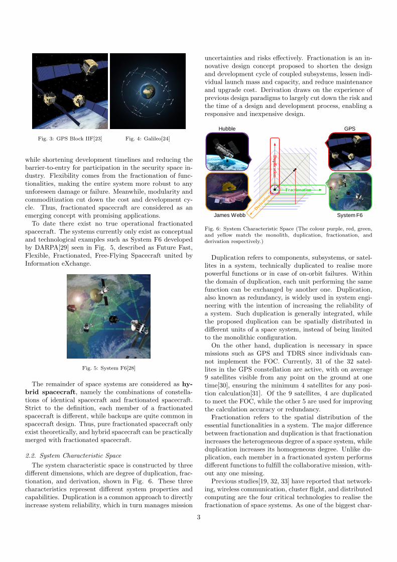
while shortening development timelines and reducing thebarrier-to-entry for participation in the security space in-dustry. Flexibility comes from the fractionation of func-tionalities, making the entire system more robust to anyunforeseen damage or failure. Meanwhile, modularity andcommoditization cut down the cost and development cy-cle. Thus, fractionated spacecraft are considered as anemerging concept with promising applications.
To date there exist no true operational fractionatedspacecraft. The systems currently only exist as conceptualand technological examples such as System F6 developedby DARPA[29] seen in Fig. 5, described as Future Fast,Flexible, Fractionated, Free-Flying Spacecraft united byInformation eXchange.
67th International Astronautical Congress (IAC), Guadalajara, Mexico, 26-30 September 2016. Copyright ©2016 by the International Astronautical Federation (IAF). All rights reserved.
IAC-16-D1.3.2 Page 3 of 12
Fig. 3: GPS Block IIF
22 Fig. 4: Galileo
23
Fractionated spacecraft decompose the monolithic
spacecraft into the heterogeneous clusters of wirelessly-
interconnected modules, each capable of sharing and
utilizing the resources throughout the entire network6,7,24
.
Unlike constellations of identical spacecraft, where each
single spacecraft in a cluster is identical or near identical,
almost every module of fractionated spacecraft has at
least one distinctive functionality25
, corresponding to
various subsystems of a monolithic one.
As DARPA describes26
, “such architecture enhances
the adaptability and survivability of space systems, while
shortening development timelines and reducing the
barrier-to-entry for participation in the security space
industry”. Flexibility comes from the fractionation of
functionalities, making the entire system more robust to
any unforeseen damage or failure. Meanwhile, modularity
and commoditization cut down the cost and development
cycle of space systems. Thus, fractionated spacecraft is an
emerging concept with a promising application prospect.
To date there exist no true operational fractionated
spacecraft. The systems currently only exist as conceptual
and technological examples such as System F6 developed
by DARPA27
seen in Fig. 5 and described as “Future Fast,
Flexible, Fractionated, Free-Flying Spacecraft united by
Information eXchange”.
Fig. 5: System F6 Satellites
26
The remainder of systems are considered as hybrid
spacecraft, namely the combinations of constellations of
identical spacecraft and fractionated spacecraft. Strict to
the definition, each member of fractionated spacecraft is
different, while backups are quite common in spacecraft
design. Thus, pure fractionated spacecraft only exist
theoretically, and hybrid spacecraft can be practically
included in fractionated spacecraft.
2.2 System Characteristic Space
The system characteristic space is constructed by three
different dimensions, which are degree of duplication,
fractionation, and derivation. These three characteristics
represent certain system properties and capabilities in the
space mission analysis and design. Duplication is a
common approach to directly increase system reliability,
which in turn manages the mission uncertainties and risks
effectively. Fractionation is an innovative design concept
proposed to shorten the design and development cycle of
coupled subsystems, lessen individual launch mass and
capacity, and reduce maintenance and upgrading cost.
Derivation draws on the experience of previous design
paradigms to largely cut down the risk and the time of a
design and development process, enabling a responsive
and inexpensive space.
Duplication refers to components, subsystems, or
satellites in a system, technically duplicated to realise
more powerful functions or in case of on-orbit failures.
Within the domain of duplication, each unit performing
the same function can be exchanged by another one.
Duplication, also known as redundancy, is widely used in
system engineering with the intention of increasing the
reliability of a system. Such duplication is generally
integrated, while the proposed duplication can be spatially
distributed in different units of a space system, instead of
being limited to the monolithic configuration.
On the other hand, duplication is necessary in space
missions such as GPS and TDRS since individuals cannot
implement the FOC. Currently, 31 of the 32 satellites in
the GPS constellation are active, with on average 9
satellites visible from any point on the ground at one
time28
, ensuring the minimum 4 satellites for any position
calculation29
. Of the 9 satellites, 4 are duplicated to meet
the FOC, while the other 5 are used for improving the
calculation accuracy or redundancy.
Fractionation refers to the spatial distribution of the
essential functionalities in a system. The major difference
between fractionation and duplication is that fractionation
increases the heterogeneous degree of a space system,
while duplication increases its homogeneous degree.
Unlike duplication, each member in a fractionated system
performs different functions to perform the collaborative
mission, without any one missing.
Previous studies18,30,31
have reported that networking,
wireless communication, cluster flight, and distributed
computing are the four critical technologies to realise the
fractionation of space systems. As one of the biggest
Fig. 5: System F6[28]
The remainder of space systems are considered as hy-brid spacecraft, namely the combinations of constella-tions of identical spacecraft and fractionated spacecraft.Strict to the definition, each member of a fractionatedspacecraft is different, while backups are quite common inspacecraft design. Thus, pure fractionated spacecraft onlyexist theoretically, and hybrid spacecraft can be practicallymerged with fractionated spacecraft.
2.2. System Characteristic Space
The system characteristic space is constructed by threedifferent dimensions, which are degree of duplication, frac-tionation, and derivation, shown in Fig. 6. These threecharacteristics represent different system properties andcapabilities. Duplication is a common approach to directlyincrease system reliability, which in turn manages mission
uncertainties and risks effectively. Fractionation is an in-novative design concept proposed to shorten the designand development cycle of coupled subsystems, lessen indi-vidual launch mass and capacity, and reduce maintenanceand upgrade cost. Derivation draws on the experience ofprevious design paradigms to largely cut down the risk andthe time of a design and development process, enabling aresponsive and inexpensive design.
Du
plica
tion
Der
ivat
ion
Fractionation
Hubble
James Webb
GPS
System F6
Fig. 6: System Characteristic Space (The colour purple, red, green,and yellow match the monolith, duplication, fractionation, andderivation respectively.)
Duplication refers to components, subsystems, or satel-lites in a system, technically duplicated to realise morepowerful functions or in case of on-orbit failures. Withinthe domain of duplication, each unit performing the samefunction can be exchanged by another one. Duplication,also known as redundancy, is widely used in system engi-neering with the intention of increasing the reliability ofa system. Such duplication is generally integrated, whilethe proposed duplication can be spatially distributed indifferent units of a space system, instead of being limitedto the monolithic configuration.
On the other hand, duplication is necessary in spacemissions such as GPS and TDRS since individuals can-not implement the FOC. Currently, 31 of the 32 satel-lites in the GPS constellation are active, with on average9 satellites visible from any point on the ground at onetime[30], ensuring the minimum 4 satellites for any posi-tion calculation[31]. Of the 9 satellites, 4 are duplicatedto meet the FOC, while the other 5 are used for improvingthe calculation accuracy or redundancy.
Fractionation refers to the spatial distribution of theessential functionalities in a system. The major differencebetween fractionation and duplication is that fractionationincreases the heterogeneous degree of a space system, whileduplication increases its homogeneous degree. Unlike du-plication, each member in a fractionated system performsdifferent functions to fulfill the collaborative mission, with-out any one missing.
Previous studies[19, 32, 33] have reported that network-ing, wireless communication, cluster flight, and distributedcomputing are the four critical technologies to realise thefractionation of space systems. As one of the biggest char-
3
acteristics of current space technologies, the incrementaluse of on-board processing[34] offers a great opportunityfor the application of fractionation. The fractionation ofsuch subsystems as attitude and orbit control subsystem(AOCS) may stimulate the decrease of its own scale, foronly certain subsystems need to be controlled instead ofthe entire spacecraft. Different from the accurate orbitmaintenance of traditional constellations, the cluster flightof fractionated spacecraft only requires appropriate rela-tive distances and orientations to ensure communicationlinks and collision avoidance[35].
Derivation refers to components, subsystems, or satel-lites in a system, whose technologies and capabilities arederivative from previous missions. On one hand one couldsay that, the more derivative elements in a system, themore mature a system is, which may imply higher relia-bility and cost-effectiveness of the entire system. Howeveron the other hand, the innovative or less derivative prod-ucts with advanced design concepts and technologies mayextend system capability or improve system performance.
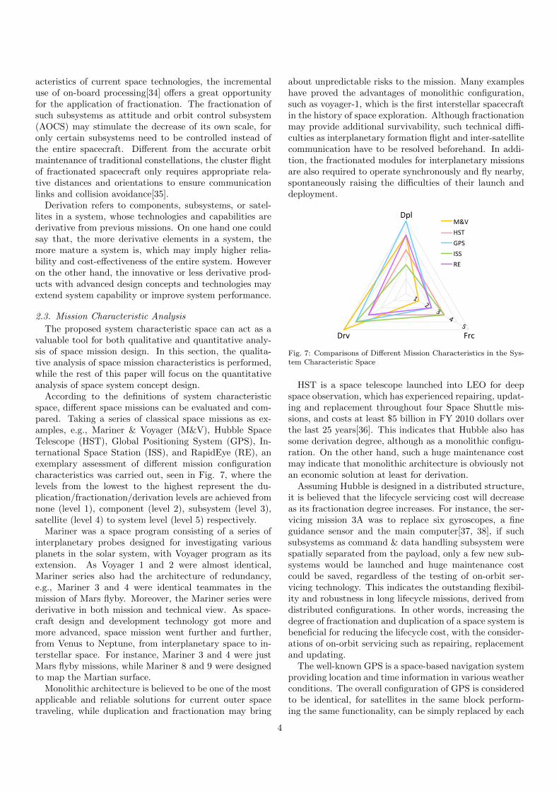
2.3. Mission Characteristic Analysis
The proposed system characteristic space can act as avaluable tool for both qualitative and quantitative analy-sis of space mission design. In this section, the qualita-tive analysis of space mission characteristics is performed,while the rest of this paper will focus on the quantitativeanalysis of space system concept design.
According to the definitions of system characteristicspace, different space missions can be evaluated and com-pared. Taking a series of classical space missions as ex-amples, e.g., Mariner & Voyager (M&V), Hubble SpaceTelescope (HST), Global Positioning System (GPS), In-ternational Space Station (ISS), and RapidEye (RE), anexemplary assessment of different mission configurationcharacteristics was carried out, seen in Fig. 7, where thelevels from the lowest to the highest represent the du-plication/fractionation/derivation levels are achieved fromnone (level 1), component (level 2), subsystem (level 3),satellite (level 4) to system level (level 5) respectively.
Mariner was a space program consisting of a series ofinterplanetary probes designed for investigating variousplanets in the solar system, with Voyager program as itsextension. As Voyager 1 and 2 were almost identical,Mariner series also had the architecture of redundancy,e.g., Mariner 3 and 4 were identical teammates in themission of Mars flyby. Moreover, the Mariner series werederivative in both mission and technical view. As space-craft design and development technology got more andmore advanced, space mission went further and further,from Venus to Neptune, from interplanetary space to in-terstellar space. For instance, Mariner 3 and 4 were justMars flyby missions, while Mariner 8 and 9 were designedto map the Martian surface.
Monolithic architecture is believed to be one of the mostapplicable and reliable solutions for current outer spacetraveling, while duplication and fractionation may bring
about unpredictable risks to the mission. Many exampleshave proved the advantages of monolithic configuration,such as voyager-1, which is the first interstellar spacecraftin the history of space exploration. Although fractionationmay provide additional survivability, such technical diffi-culties as interplanetary formation flight and inter-satellitecommunication have to be resolved beforehand. In addi-tion, the fractionated modules for interplanetary missionsare also required to operate synchronously and fly nearby,spontaneously raising the difficulties of their launch anddeployment.
67th International Astronautical Congress (IAC), Guadalajara, Mexico, 26-30 September 2016. Copyright ©2016 by the International Astronautical Federation (IAF). All rights reserved.
IAC-16-D1.3.2 Page 4 of 12
characteristics of the current space technologies, the
incremental use of on-board processing32
offers a great
opportunity for the application of fractionation. Due to the
fractionation of attitude and orbit control subsystem
(AOCS), only a few fractionated subsystems need to be
controlled instead of the whole monolithic spacecraft,
stimulating the decrease of its own scale. Moreover,
fractionated systems do not necessitate accurate orbit
maintenance, only appropriate relative distances and
orientations to ensure communication links and collision
avoidance33
.
Derivation refers to components, subsystems, or
satellites in a system, whose technologies and capabilities
are derivative from previous missions. On the one hand
one could say that, the more derivative elements in a
system, the more mature a system is, which may imply
higher reliability and cost-effectiveness of the entire
system; however on the other hand, the innovative or less
derivative products with advanced design concepts and
technologies may extend system capability and improve
system performance.
2.3 Mission Characteristic Analysis
The proposed system characteristic space can act as a
valuable tool for both qualitative and quantitative analysis
of space mission design. In this section, the qualitative
analysis of space mission characteristics is performed,
while the rest of this paper will focus on the quantitative
analysis of space system concept design.
According to the definitions of system characteristic
space, different space missions can therefore be evaluated
and compared in the standard architecture. Taking a series
of classical space missions as examples, e.g., Mariner &
Voyager (M&V), Hubble Space Telescope (HST), Global
Positioning System (GPS), International Space Station
(ISS), and RapidEye (RE), an exemplary assessment of
different mission configuration characteristics was carried
out, seen in Fig. 6, where the levels from the lowest to the
highest represent the duplication/fractionation/derivation
levels are achieved from none (level 1), component (level
2), subsystem (level 3), satellite (level 4) to system level
(level 5) respectively.
Mariner is a space program consisting of a series of
interplanetary probes designed for investigating various
planets in the solar system, with Voyager program as its
extension. As Voyager 1 and 2 were almost identical,
Mariner series also had the architecture of redundancy,
e.g., Mariner 3 and 4 were identical teammates in the
mission of Mars flyby. Moreover, Mariner series were
derivative in both mission and technical view. As
spacecraft design and development technology got more
and more advanced, space mission went further and
further, from Venus to Neptune, from interplanetary space
to interstellar space. For instance, Mariner 3 and 4 were
just Mars flyby missions, while Mariner 8 and 9 were
designed to map the Martian surface.
Monolithic architecture is believed to be one of the
most applicable and reliable solutions for current outer
space traveling, while duplication and fractionation may
bring about unpredictable risks to the mission. Many
examples have proved the advantage of monolithic
systems, such as voyager-1, which is the first interstellar
spacecraft in the history of space exploration. Although
fractionation may provide additional survivability, such
technical difficulties as interplanetary formation flight
and inter-satellite communication have to be resolved
beforehand. In addition, the fractionated modules for
interplanetary missions are also required to operate
synchronously and fly nearby, spontaneously raising the
difficulties of their launch and deployment.
1 2 3 4 5
Dpl
Drv Frc
M&V
HST
GPS
ISS
RE
Fig. 6: Space Mission Characteristics
Hubble Space Telescope, which is a space telescope
launched into low earth orbit for deep space observation,
has experienced repairing, updating and replacement
throughout four Space Shuttle missions, which costs at
least $5 billion in FY 2010 dollars over the last 25 years34
.
This indicates that Hubble also has some derivation
degree, although as a monolithic configuration. On the
other hand, such a huge maintenance cost may indicate
that monolithic architecture is obviously not an economic
one at least for derivation.
Assume Hubble is designed in a distributed structure,
it is believed that the lifecycle servicing cost will decrease
as its fractionation degree increases. For instance, the
servicing mission 3A was to replace six gyroscopes, a
fine guidance sensor and the main computer35,36
, if such
subsystems as command & data handling subsystem were
spatially separated from the payload, only a few new
subsystems would be launched and huge maintenance
cost could be saved, regardless of the testing of on-orbit
servicing technology. This indicates the outstanding
flexibility and robustness in long lifecycle missions,
derived from distributed configurations. In other words,
Fig. 7: Comparisons of Different Mission Characteristics in the Sys-tem Characteristic Space
HST is a space telescope launched into LEO for deepspace observation, which has experienced repairing, updat-ing and replacement throughout four Space Shuttle mis-sions, and costs at least $5 billion in FY 2010 dollars overthe last 25 years[36]. This indicates that Hubble also hassome derivation degree, although as a monolithic configu-ration. On the other hand, such a huge maintenance costmay indicate that monolithic architecture is obviously notan economic solution at least for derivation.
Assuming Hubble is designed in a distributed structure,it is believed that the lifecycle servicing cost will decreaseas its fractionation degree increases. For instance, the ser-vicing mission 3A was to replace six gyroscopes, a fineguidance sensor and the main computer[37, 38], if suchsubsystems as command & data handling subsystem werespatially separated from the payload, only a few new sub-systems would be launched and huge maintenance costcould be saved, regardless of the testing of on-orbit ser-vicing technology. This indicates the outstanding flexibil-ity and robustness in long lifecycle missions, derived fromdistributed configurations. In other words, increasing thedegree of fractionation and duplication of a space system isbeneficial for reducing the lifecycle cost, with the consider-ations of on-orbit servicing such as repairing, replacementand updating.
The well-known GPS is a space-based navigation systemproviding location and time information in various weatherconditions. The overall configuration of GPS is consideredto be identical, for satellites in the same block perform-ing the same functionality, can be simply replaced by each
4
other. Satellites among different blocks also can be con-sidered as functionally identical, since they implement thesame function but manifest different behaviours. Such adifference between new blocks and old blocks can be clas-sified as derivation in an identical space system, that is,new blocks retain the same function of old ones, but havesome updates and reinforcements, e.g., GPS block IIIAaimed to prevent technical mistakes still threatening GPSblock IIF, in addition to achieving some more ambitiousgoals[39, 40]. Last but not the least, such a homogeneousconfiguration indeed makes GPS lasting for a long lifetime,compared with any monolithic navigation satellite.
The US GPS, associated with the Russian GLONASS,the European Galileo, makes up the Global NavigationSatellite System (GNSS). As to functionality, each systemis near identical, despite different system performances.Furthermore, all of them can cooperate to implement moreambitious missions. Conceptually, these systems are un-likely to be derivative from each other, although each onecan be derivative from itself.
The situation of ISS is a bit different. In terms of systemfunctionality, it has a modular configuration, with varietiesof functionalities fractionated. However, all the modulesare docked, leaving the entire system as a monolith. There-fore, ISS can be considered as the origin of fractionation,which is also the boundary of monolith.
The monolithic configuration of ISS has its own advan-tages and disadvantages. On one hand, all the capsulesor modules are docked together, so that wireless commu-nication devices and other mass penalty caused by frac-tionation can be avoid naturally. On the other hand,components to be launched have to possess the ability ofrendezvous and dock, which inevitably increases the costand complexity of the maintenance and development of aspace station. Moreover, both scalability and updatabil-ity are largely limited by the initial design of the system,which restricts the architecture adjustment and technicaladvancement. If the space station was designed in a dis-tributed architecture, this mission might be completed in amore simple and cooperative way. It is because most cap-sules or modules can be designed separately without anydocking ports, saving a lot of cost and time among differ-ent space agents. Therefore, reconfiguration and upgradescan be realised, even wireless communication framework ispossible to be changed to some extent.
RapidEye refers to a constellation of five identical ob-servation satellites, which is operated by BlackBridge AG,providing geospatial information for decision making. Theconfiguration of RapidEye is no doubt to be identical,since all the satellites are equally deployed in the sameorbital plane, containing the same sensors[41, 42]. Differ-ent from the above constellations, RapidEye is comprisedof small and inexpensive platforms with COTS componets.This indicates that tailored and complicated structures canbe replaced by modular and standardlised designs, whichbrings in additional derivation.
3. Configuration Design Architecture
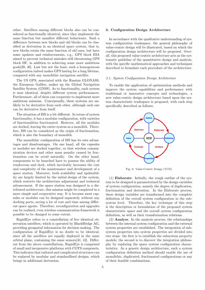
In accordance with the qualitative understanding of sys-tem configuration tradespace, the general philosophy ofvalue-centric design will be illustrated, based on which theconfiguration design architecture will be proposed. Over-all, this proposed value-centric architecture acts as the sys-tematic guideline of the quantitative design and analysis,with the specific mathematical approaches and techniquesdescribed to formulate each procedure of the architecture.
3.1. System Configuration Design Architecture
To enable the application of optimization methods andimprove the system capabilities and performance withtraditional or innovative concepts and technologies, anew value-centric design architecture based upon the sys-tem characteristic tradespace is proposed, with each stepspecifically described as follows:
67th International Astronautical Congress (IAC), Guadalajara, Mexico, 26-30 September 2016. Copyright ©2016 by the International Astronautical Federation (IAF). All rights reserved.
IAC-16-D1.3.2 Page 5 of 12
increasing the degree of fractionation and duplication of a
space system is beneficial for reducing the lifecycle cost,
with the considerations of on-orbit servicing such as
repairing, replacement and updating.
The well-known Global Positioning System is a
space-based navigation system providing location and
time information in various weather conditions.
The overall configuration of GPS is considered to be
identical. Satellites in the same block, which perform the
same functionality and can be simply replaced by each
other, are no doubts to be identical. Satellites among
different blocks also can be considered as functionally
identical, since they implement the same function but
manifest different behaviours. Such a difference between
new blocks and old blocks can be classified as derivation
in an identical space system, that is, new blocks retain the
same function of old ones, but have some updates and
reinforcements, e.g., GPS block IIIA aimed to prevent
technical mistakes still threatening GPS block IIF, apart
from achieving some more ambitious goals37,38
. Last but
not the least, such an identical configuration indeed
makes GPS lasting for a long lifetime, compared with any
monolithic navigation satellite.
The US GPS, associated with the Russian GLONASS,
the European Galileo, makes up the Global Navigation
Satellite System (GNSS). As to functionality, each system
is near identical, despite different system performances.
Furthermore, all of them can cooperate to implement
more ambitious missions. Conceptually, these systems are
unlikely to be derivative from each other, although each
one can be derivative from itself.
The situation of International Space Station is a bit
different. In terms of system functionality, it has a
modular configuration, with varieties of functionalities
fractionated. However, all the modules are docked,
leaving the entire system as a monolith. Therefore, ISS
can be considered as the origin of fractionation, which is
also the boundary of monolith.
The monolithic configuration of ISS has its own
advantages and disadvantages. On the one hand, all the
capsules or modules are docked together, so that wireless
communication devices and other mass penalty caused by
fractionation can be avoid naturally. On the other hand,
whatever to be launched has to have the ability of
rendezvous and dock, which inevitably increases the cost
and complexity of the maintenance and development of a
space station. Moreover, both scalability and updatability
are largely limited by the initial design of the system,
which restricts the architecture adjustment and technical
advancement.
If the space station was designed in a distributed
architecture, this mission might be completed in a more
simple and cooperative way. It is because most capsules
or modules can be designed separately without any
docking ports, saving a lot of cost and time among
different space agents. Therefore, reconfiguration and
upgrades can be realised, even wireless communication
framework is possible to be changed to some extent.
RapidEye refers to a constellation of five identical
observation satellites, which is operated by BlackBridge
AG, providing geospatial information for decision
making. The configuration of RapidEye is no doubt to be
identical, since all the satellites are equally deployed in
the same orbital plane, containing the same sensors39,40
.
Different from the above constellations, RapidEye is
comprised of small satellites, rather than large ones. This
indicates that tailored and complicated structures can be
replaced by modular and flexible ones, which brings in
additional derivative degree.
3. Configuration Design Architecture
In accordance with the qualitative understanding of
system configuration tradespace, the general philosophy
of value-centric design will be illustrated, based on which
the configuration design architecture will be proposed.
Overall, this proposed value-centric architecture acts as
the systematic guideline of the quantitative design and
analysis, with the specific mathematical approaches and
techniques described to formulate each procedure of the
architecture.
3.1 System Configuration Design Architecture
To enable the application of optimization methods and
improve the system capabilities and performance with
traditional or innovative concepts and technologies, a new
value-centric design architecture based upon the system
characteristic tradespace is proposed, with each step
specifically described as follows:
Elaborate
AnalyseEvaluate
Optimize
Outline
Definition
Properties
Value VCD
Fig.7: Value-Centric Design (VCD)
(1) Elaborate. Initially, the rough outline of the system
to be designed is parameterized by the design variables of
system configuration, namely the degree of duplication,
fractionation and derivation. In the Elaborate process,
Fig. 8: Value-Centric Design (VCD)
(1) Elaborate. Initially, the rough outline of the sys-tem to be designed is parameterized by the design variablesof system configuration, namely the degree of duplication,fractionation and derivation. In the Elaborate process,these design variables are transformed into the completedefinition of the overall system configuration in the sub-system level. Therefore, the key technique of this stepis the description or formulation of the proposed systemcharacteristic space and the overall system configurationdefinition, as well as their transformation relations.
(2) Analyse. In the analysis process, the relationshipsbetween the internal system configuration and the externalsystem properties are established. The integration of sub-system properties into system properties are divided intotwo steps: the first is to establish the subsystem propertymodels; the second is to discover the integration philoso-phy by exploring the space system configuration charac-teristics. As a generic design architecture, such a systemconfiguration definition method should enable the use ofmonolithic, duplicated, fractionated configurations or anyof their feasible combinations.
5

(3) Evaluate. In the evaluate process, the overall sys-tem value is calculated by appropriate system value mod-els to determine whether the system requirements are met,based on different system properties. As the major elementdistinguishing the value-centric design from the traditionalone, the value model is the enabling factor of the optimiza-tion of the concept design process, while the technique dif-ficulties reside how to measure different system propertiesin the same dimension. One of the possible approaches isto transfer them into the dimension of cost, however thecost characteristics of some system properties are currentlyunclear.
(4) Optimize. In the optimize process, system value isquantified as objective function or the output of the singledesign loop, which is returned to design variables as feed-back. Such a data flow loop distinguishes the value-centricdesign from the human-in-the-loop of the requirement-centric design. Under the proposed value-centric designarchitecture, the optimization process is realised by opti-mization algorithms rather than the manual modification.Therefore, the theoretical optimal configuration design canbe achieved, instead of reaching an empirically feasible so-lution to meet the mission requirements. In conclusion,the proposed system configuration design architecture hasbeen established based upon the value-centric philosophy.The aim of enabling the use of both traditional and in-novative design concepts and technologies has been ac-complished theoretically, with the specific approaches andtechniques described in the following sections.
3.2. Formulation of System Characteristic Space
Assuming m satellites in a space system, and n types ofsubsystems in each satellite, in this case, the elements ofthe System Design Matrix Dk are the particular property,k, of every subsystem on every satellite. Where each ele-ment dij (i=1,2,· · · ,m, j=1,2,· · · ,n) denotes the value ofthat type of subsystems property on that particular satel-lite. For example, for the property “mass”, the value ofelement d1,2 is the total mass of all subsystems of type 2 onsatellite 1. There is a separate D matrix for each relevantproperty, e.g. mass, cost, reliability, etc.
D =
d11 d12 . . . d1nd21 d22 . . . d2n...
.... . .
...dm1 dm2 . . . dmn
(1)
This system design matrix can be understood in twodimensions: on one hand, each row defines the differentdesigns of these n subsystems in a certain satellite; onthe other hand, each column displays the distribution ofcertain subsystem in the system or across the satellites.
For additive system properties such as mass and cost,each element dij is simply the product of the unit prop-erty of that subsystem times the degree of duplication. Fornon-additive properties, such as reliability, a more sophis-ticated function of degree of duplication is used.
dij = nijuij (2)
Where, nij and uij are the degree of duplication and thesubsystem unit design property of subsystem j in satellitei respectively. Let
N =
n11 n12 . . . n1nn21 n22 . . . n2n
......
. . ....
nm1 nm2 . . . nmn
(3)
U =
u11 u12 . . . u1nu21 u22 . . . u2n
......
. . ....
um1 um2 . . . umn
(4)
Where, we call N the System Configuration Matrix,defining the number of identical or near identical subsys-tems in each satellite, or the degree of duplication of eachsubsystem in each satellite. Once the System Configura-tion Matrix N is determined, the system configuration canthereby be determined. The Unit Design Property MatrixU can be used for system property analysis to representany kind of property of each subsystem conceptual design.Therefore
D = N ◦ U (5)
3.2.1. Duplication, Fractionation and Sequence
Mathematically, degree of duplication can be definedas the number of identical or near identical subsystemsscattered in the overall system, according to its definition.Therefore, the System Duplication Vector P can be calcu-lated from the System Configuration Matrix N .
p =[p1 p2 . . . pn
]T(6)
Where, each pj is the sum of elements in each columnof N .
pj =
m∑i=1
nij (7)
Similarly, the System Fractionation Vector F can bemathematically determined by the number of differentsatellites with the same certain subsystem.
F =[f1 f2 . . . fn
]T(8)
Where, each fj is the number of nonzero elements ineach column of N .
It is obvious that the System Duplication Vector P andthe System Fractionation Vector F can be derived fromthe System Configuration Matrix N , called forward trans-formation. However, the System Configuration Matrix Ncannot be derived only from the System Duplication Vec-tor P and the System Fractionation Vector F . To make
6
this transformation reversible, the System Sequence Vec-tor Q is introduced to complement the information lostduring the forward transformation.
Q =[q1 q2 . . . qn
]T(9)
Where, each qj is the sequence number of each subsys-tem permutation in the overall system, determined by itsranking in the Subsystem Arranging Matrix Aj .
Aj =
aj,11 aj,12 . . . aj,1naj,21 aj,22 . . . aj,2n
......
. . ....
aj,m1 aj,m2 . . . aj,mn
(10)
Where, Aj is the Subsystem Arranging Matrix of sub-system j, and nj is the corresponding total number ofpossible arrangements. The calculation process of nj canbe considered as one of the classical problems in combina-torics, pj unlabelled ball in fj labelled buckets.
nj =
(fjm
)(fj − 1
pj − 1
)(11)
Moreover, all the Subsystem Arranging Matrices Aj to-gether constitute the System Arranging Matrix A.
A =[A1 A2 . . . An
](12)
The System Arranging Matrix A is derived by the Sys-tem Duplication Vector P and the System FractionationVector F . Once given the System Duplication Vector Pand the System Fractionation Vector F , all the possiblearrangements of the system configuration can be deter-mined, and the System Arranging Matrix A is the assem-bly of these permutations. Meanwhile, these arrangementsare sorted from largest to smallest, column by column, inthe System Arranging Matrix A.
Therefore, the System Duplication Vector P and theSystem Fractionation Vector F , associated with the Sys-tem Sequence Vector Q, have established a one-to-one cor-respondence with the System Configuration MatrixN , andthe transformation from P , F and Q to N can be calledbackward transformation, namely, the reversible transfor-mation of the forward one.
For instance, assume that m=6, n=5, and the SystemConfiguration Matrix N is as follows
N =
1 0 0 0 00 2 0 0 01 2 1 0 00 0 1 0 00 0 0 1 10 0 0 0 2
(13)
Through the forward transformation, we can obtain theSystem Duplication Vector P and the System Fractiona-tion Vector F as follows
P =[2 4 2 1 3
]T(14)
F =[2 2 2 1 2
]T(15)
Take the sequence calculation of subsystem j=2 as anexample. Since p2=4 and f2=2, the Subsystem ArrangingMatrix A2 can be derived with the values below.
A2 =
3 3 . . . 0 . . . 01 0 . . . 2 . . . 00 1 . . . 2 . . . 00 0 . . . 0 . . . 00 0 . . . 0 . . . 10 0 . . . 0 . . . 3
(16)
Where
n2 =
(f2m
)(f2 − 1
p2 − 1
)= 45 (17)
It is worth noting that the 20th column vector of A2
matches the configuration of subsystem j = 2, that is, the2nd column vector of N , namely
A2(20) = N(2) (18)
Where, Aj(k) and N(k) are the kth column vector of thematrices Aj and N respectively. Thus, we can concludethat q2=20. Similarly, the value of the other elements ofthe System Sequence Vector Q can also be calculated.
Q =[2 20 10 5 30
]T(19)
The above exemplifies the forward transformation, whilethe following is to implement the backward transforma-tion. Since matrices P , F and Q are defined, as the deriva-tive of P and F , the System Arranging Matrix A is alsoavailable. Therefore, the System Configuration Matrix Ncan be deduced by column vectors of matrix A.
N =[A1(2) A2(20) A3(10) A4(5) A5(30)
]T(20)
3.2.2. Derivation
To achieve the mathematical definition of derivation, therelationships of subsystems in different satellites need to beinvestigated first, that is, the relationships of the elementsin the same column of matrix U .
Start from one of the simplest conditions that each sub-system adopts the same design paradigm or the sameCOTS component, so that all the elements of certain sub-system design option, which are in the same column ofmatrix U , can be considered as identical.
uij = uj(i = 1, 2, · · · ,m) (21)
Or
Uc =
u1 u2 . . . unu1 u2 . . . un...
.... . .
...u1 u2 . . . un
(22)
7
For the condition that subsystems differ from each otherin different satellites, the System Derivation Matrix is in-troduced, which defines the degree of derivation of eachsubsystem in each satellite.
V =
v11 v12 . . . v1nv21 v22 . . . v2n...
.... . .
...vm1 vm2 . . . vmn
(23)
Where, each vij presents the degree of derivation in per-centage for each subsystem in each satellite. The degreeof derivation is similar to the Heritage Factor discussedin the Space Mission Analysis and Design[34], defined asthe percentage of a subsystem that is identical to previousspacecraft by mass. Therefore, the System Derivation Ma-trix V denotes the recurring characteristic of subsystemdesign from previous ones, which might have significantimpacts on system properties, such as reliability.
U = V ◦ Uc (24)
For real and complex cases like GPS and Galileo, a seriesof System Derivation Matrices can be applied to exhibitthe evolution of the design of satellites.
U =
ng∑k=1
Vk ◦ Uk (25)
Where, ng is the generation number of the satellite de-sign, Uk is the Unit Design Property Matrix of generationk, and Vk is its corresponding System Derivation Matrix.
3.3. Effects Analysis on Reliability
Having established the mathematical fundamentals ofthe system characterisation, this section aims at evaluat-ing the effects of degree of duplication, fractionation, andderivation on the system reliability. Based upon the sub-system property modelling, system characteristics will beanalysed from the subsystem level. The integration of sys-tem properties will be subsequently implemented to buildthe mapping relations between system designs and systemproperties, enabling the analyse and evaluate processesin the proposed value-centric design architecture.
3.3.1. Subsystem Reliability Models
Mathematically, reliability is defined by Thompson[43]and Davidson[44] as the probability of a component, de-vice, or system performing its intended function withoutfailure for a specific period of time under nominal con-ditions. To describe how the failure occurrences are dis-tributed over time, we generally use different types of prob-ability distributions, such as the exponential, Weibull, log-normal, and extreme-value distributions.
Due to its mathematical simplicity, flexibility and ap-plicability to the modelling of different failure behaviours,and the demonstrated ability to fit most lifetime data, the
Weibull distribution[44] is one of the most widely used dis-tributions in reliability analysis. The probability densityfunction (PDF) of the Weibull distribution with a contin-uous random variable can be written as follows.
r(t) =
{ (βt
)(tη
)(β−1)
e−( tη )β
t ≥ 0
0 t < 0(26)
Where, t is the satellite lifetime in orbit before failure,β is the dimensionless shape parameter, η is the scale pa-rameter in units of time. Consequently, the reliability cu-mulative distribution function (CDF) can be expressed as
R(t) = e−( tη )β
(27)
This is the reliability model used for the different spacesubsystems and systems in this paper. For each specificcase, the parameters β and η are calculated by parameterestimation methods, among which Maximum LikelihoodEstimation (MLE) and Bayesian theory in combinationwith Markov Chain Monte Carlo simulations (MCMC) aretwo of the most effective and applicable. The selection ofthese two methods is mainly determined by the samplesize of the database.
Based on the 1584 Earth-orbiting satellites successfullylaunched from January 1990 to October 2008 recorded inthe SpaceTrak database (STD), Castet and Saleh[45, 46]developed and fitted a parametric reliability model for ac-tual satellite subsystems. Meanwhile, Guo[47] conductedreliability modelling particularly for small satellite subsys-tems, and found that MCMC is suitable for such databaseswith small sample sizes and censored data problems asSmall Satellite Anomalies Database (SSAD), which covers222 small satellites launched over the last few decades. Itis apparent that SSAD is more applicable for the reliabil-ity analysis of small satellite subsystems, while STD mightappeal to generic systems.
In Table 1, the estimated Weibull parameters are listedfor both STD and SSAD. The abbreviations used here arePLS for Payload Subsystem, EPS for Electrical Power Sub-system, TTC for Telemetry, Tracking and Command Sub-system, CDH for Command and Data Handling Subsys-tem, ACS for Attitude Control Subsystem, OCS for OrbitControl Subsystem, TCS for Thermal Control Subsystem,and SAS for Solar Array Subsystem.
3.3.2. Reliability Analysis
Prior to integrating the system reliability, preliminaryeffects analyses of duplication and fractionation on inde-pendent subsystems are carried out to help understandtheir impacts on the overall system reliability, using theparameters in Table 1. As shown in Fig. 9, duplicatedsubsystems enjoy a continuous reliability growth with theincrease of the degree of duplication, while fractionatedsubsystems experience a drop-down and a recovery period,yet still cannot perform as reliable as duplication at the
8
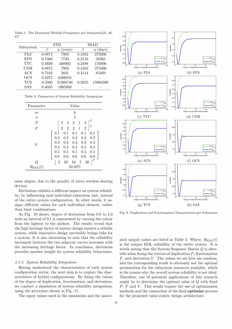
Table 1: The Estimated Weibull Parameters per Subsystem[45, 46,47]
SubsystemSTD SSAD
β η (years) β η (days)PLS 0.8874 7983 0.4162 275006EPS 0.7460 7733 0.3110 58385TTC 0.3939 400982 0.2588 176896CDH 0.8874 7983 0.4162 275006ACS 0.7182 3831 0.4144 85409OCS 0.3375 6206945 - -TCS 0.3560 21308746 0.2655 15068200SAS 0.4035 1965868 - -
Table 2: Parameters of System Reliability Integration
Parameter Value
m 6n 5
P[
2 4 2 1 3]T
F[
2 2 2 1 2]T
V
0.1 0.1 0.1 0.1 0.10.2 0.2 0.2 0.2 0.20.3 0.3 0.3 0.3 0.30.4 0.4 0.4 0.4 0.40.5 0.5 0.5 0.5 0.50.6 0.6 0.6 0.6 0.6
Q
[2 20 10 5 30
]TREOL(t) 33.88%
same degree, due to the penalty of extra wireless sharingdevices.
Derivation exhibits a different impact on system reliabil-ity, by influencing each individual subsystem unit, insteadof the entire system configuration. In other words, it as-signs different values for each individual element, ratherthan their combinations.
As Fig. 10 shows, degree of derivation from 0.0 to 1.0with an interval of 0.1 is represented by varying the colourfrom the lightest to the darkest. The results reveal thatthe high heritage factor of mature design ensures a reliablesystem, while innovative design inevitably brings risks fora system. It is also interesting to note that the reliabilityincrement between the two adjacent curves increases withthe increasing heritage factor. In conclusion, derivationprovides another insight for system reliability behaviours.
3.3.3. System Reliability Integration
Having understood the characteristics of each systemconfiguration vector, the next step is to explore the char-acteristics of hybrid configurations. By fixing the valuesof the degree of duplication, fractionation, and derivation,we conduct a simulation of system reliability integration,using the procedure shown in Fig. 11.
The input values used in the simulation and the associ-
0 5 10 15 20
0.65
0.7
0.75
0.8
0.85
0.9
0.95
1
Degree of Duplication/Fractionation
Rel
iabi
lity
PLSdpl
PLSfrc
(a) PLS
0 5 10 15 20
0.5
0.6
0.7
0.8
0.9
1
Degree of Duplication/Fractionation
Rel
iabi
lity
EPSdpl
EPSfrc
(b) EPS
0 5 10 15 20
0.55
0.6
0.65
0.7
0.75
0.8
0.85
0.9
0.95
1
Degree of Duplication/Fractionation
Rel
iabi
lity
TTCdpl
TTCfrc
(c) TTC
0 5 10 15 20
0.65
0.7
0.75
0.8
0.85
0.9
0.95
1
Degree of Duplication/Fractionation
Rel
iabi
lity
CDHdpl
CDHfrc
(d) CDH
0 5 10 15 20
0.6
0.65
0.7
0.75
0.8
0.85
0.9
0.95
1
Degree of Duplication/Fractionation
Rel
iabi
lity
ACSdpl
ACSfrc
(e) ACS
0 5 10 15 20
0.8
0.85
0.9
0.95
1
Degree of Duplication/Fractionation
Rel
iabi
lity
OCSdpl
OCSfrc
(f) OCS
0 5 10 15 20
0.7
0.75
0.8
0.85
0.9
0.95
1
Degree of Duplication/Fractionation
Rel
iabi
lity
TCSdpl
TCSfrc
(g) TCS
0 5 10 15 20
0.8
0.85
0.9
0.95
1
Degree of Duplication/Fractionation
Rel
iabi
lity
SASdpl
SASfrc
(h) SAS
Fig. 9: Duplication and Fractionation Characteristics per Subsystem
ated output values are listed in Table 2. Where, REOL(t)is the output EOL reliability of the entire system. It isworth noting that the System Sequence Matrix Q is alter-able when fixing the vectors of duplication P , fractionationF , and derivation V . The values we set here are random,and the corresponding result is obviously not the optimalpermutation for the subsystem resources available, whichis the reason why the overall system reliability is not ideal.Therefore, one of potential applications of this researchmight be to determine the optimal value of Q with fixedP , F and V . This would require the use of optimizationmethods and the connection of the final optimize processfor the proposed value-centric design architecture.
9

0 5 10 150.82
0.84
0.86
0.88
0.9
0.92
0.94
0.96
0.98
1
Time ( yrs )
Rel
iabi
lity
0
0.1
0.2
0.3
0.4
0.5
0.6
0.7
0.8
0.9
1
(a) PLS
0 5 10 15
0.65
0.7
0.75
0.8
0.85
0.9
0.95
1
Time ( yrs )
Rel
iabi
lity
0
0.1
0.2
0.3
0.4
0.5
0.6
0.7
0.8
0.9
1
(b) EPS
0 5 10 150.65
0.7
0.75
0.8
0.85
0.9
0.95
1
Time ( yrs )
Rel
iabi
lity
0
0.1
0.2
0.3
0.4
0.5
0.6
0.7
0.8
0.9
1
(c) TTC
0 5 10 150.82
0.84
0.86
0.88
0.9
0.92
0.94
0.96
0.98
1
Time ( yrs )
Rel
iabi
lity
0
0.1
0.2
0.3
0.4
0.5
0.6
0.7
0.8
0.9
1
(d) CDH
0 5 10 150.7
0.75
0.8
0.85
0.9
0.95
1
Time ( yrs )
Rel
iabi
lity
0
0.1
0.2
0.3
0.4
0.5
0.6
0.7
0.8
0.9
1
(e) ACS
0 5 10 150.88
0.9
0.92
0.94
0.96
0.98
1
Time ( yrs )
Rel
iabi
lity
0
0.1
0.2
0.3
0.4
0.5
0.6
0.7
0.8
0.9
1
(f) TCS
Fig. 10: Derivation Characteristic per Subsystem (The colourbarindicates degree of derivation)
4. Conclusion
Aiming at overcoming the drawbacks inherent in thetraditional requirement-centric design philosophy, this pa-per has developed a new value-centric configuration designarchitecture to enable the exploration of the effect of emer-gence of the latest space concepts and technologies.
After the categorisation of various space systems, threeconfiguration characteristics were generalised to constructthe system characteristic space. Based on such a space,the connection has been built between mission concept de-sign and system configuration characteristics, enabling thequalitative analysis of the feasibility and applicability ofdifferent system configurations for different mission scopes.In other words, a mission concept can be analysed anddesigned in the system characteristic space, where eachdimension reflects different characteristics of the overallconfiguration. Such a system characteristic perspectivemay offer designers or users a better understanding of thelimits and potentials of a mission, beneficial for missionmodification or extension.
In accordance with the definitions of the system char-acteristic space, the mathematical fundamentals of the
67th International Astronautical Congress (IAC), Guadalajara, Mexico, 26-30 September 2016. Copyright ©2016 by the International Astronautical Federation (IAF). All rights reserved.
IAC-16-D1.3.2 Page 10 of 12
Having understood the characteristics of each system
configuration vector, our next interest is to explore the
characteristics of hybrid configurations. When fixing the
values of the degree of duplication, fractionation, and
derivation, we carried out a simulation of the system
reliability integration, whose procedures are shown in Fig.
10.
System Reliability
Duplicated reliability Integrated reliability
DerivationConfiguration
Space
System Definition
System configuration matrix
Subsystem Reliability
Wireless sharing reliability modelSubsystem reliability model
Duplication Fractionation Sequence
Fig. 10: System Reliability Integration Process
The input values used in the simulation and the
associated output values are listed in Table 2.
Table 2: Parameters of System Reliability Integration
Parameters Values
𝑚 6
𝑛 5
𝑃 [2 4 2 1 3]T
𝐹 [2 2 2 1 2]T
𝑉
[ 0.1 0.1 0.1 0.1 0.10.2 0.2 0.2 0.2 0.20.3 0.3 0.3 0.3 0.30.4 0.4 0.4 0.4 0.40.5 0.5 0.5 0.5 0.50.6 0.6 0.6 0.6 0.6]
𝑄 [2 20 10 5 30]T
𝑅𝐸𝑂𝐿(𝑡) 33.88%
Where, 𝑅𝐸𝑂𝐿(𝑡) is the output EOL reliability of the
entire system. It is worth noting that the System Sequence
Matrix 𝑄 is alterable when fixing degree of duplication,
fractionation and derivation. The value we set here is
obviously not the best permutation for all the subsystem
resources available, which is the reason why the overall
system reliability is not ideal. Therefore, one of potential
applications beneficial for system designers in the concept
design phase might be to determine the optimal 𝑄 for the
fixed 𝑃, 𝐹 and 𝑉, which requires the use of optimization
methods and build the final Optimize process for the
proposed value-centric configuration design architecture.
4. Conclusion
Aiming at overcoming the drawbacks inherent in the
traditional requirement-centric design philosophy, this
paper has developed a new value-centric configuration
design architecture to enable the applications of the latest
space concepts and technologies.
After the categorisation of various space systems,
three configuration characteristics were generalised to
construct the system characteristic space. Based on such a
space, a bridge has been built between mission concept
design and system configuration characteristics, enabling
the qualitative analysis of the feasibility and applicability
of different system configurations for different mission
scopes. In other words, mission concept can be analysed
and designed in the system configuration space, where
each dimension reflected different characteristics of the
overall configurations. On the other hand, such a system
characteristic perspective may give designers or users a
better understanding of the limits and potentials of a
mission, beneficial for mission modification or extension.
In accordance with the definitions of the system
characteristic space, the mathematical fundamentals of the
proposed value-centric architecture has been developed,
establishing the one-to-one correspondence between the
overall system configuration matrix and the three
dimensions of system configuration characteristics. The
mathematical model can improve certain system property
by altering the overall system configuration, which may
benefit the applications of the quantitative analysis,
design and optimization on system configurations.
Based on the subsystem property modelling, the effect
analyses and simulations have been implemented on
different system configuration characteristics to explore
the configuration design space. The integration of system
properties in the proposed value-centric concept design
architecture has been accomplished to build the mapping
relations between the system configuration design and the
system properties. This may be one of the enabling
factors for the applications of optimization methods in the
system characteristic space to search for the optimal
concept design, with certain system property as objective
function.
5. Future Work
Having established the value-centric architecture of
the system configuration design space, the future research
will focus on the exploration and application of the design
architecture to explore the optimal design configuration
under various conditions.
As mentioned before, one of the potential applications
beneficial for system designers in the concept design
phase may be to determine the optimal permutation of
available subsystem resources. It is worth noting that the
variables of such optimization problems are all integers,
which is one of the most outstanding characteristics of the
proposed permutation optimization problems with certain
system property as objective function. This is called the
mixed integer nonlinear programming problems in the
Fig. 11: Integration Procedures of System Reliability
proposed value-centric architecture was developed, estab-lishing the one-to-one correspondence between the over-all system configuration matrix and the three dimensionsof system characterisation. The mathematical model canimprove a given system property by exploring the effectof different subsystem selections, beneficial for the appli-cations of the quantitative analysis and optimization onsystem designs.
Based on the subsystem property modelling, the effectanalyses and simulations have been implemented on differ-ent system configuration characteristics to explore the con-figuration design space. The integration of system proper-ties in the proposed value-centric concept design architec-ture has been accomplished to build the mapping relationsbetween the system configuration design and the systemproperties. This may be one of the enabling factors forthe applications of optimization methods in the systemcharacteristic space to search for the optimal configurationdesign, with a system property as the objective function.
The quantification of system values and adoption ofoptimization algorithms are two major advantages ofthe proposed value-centric design architecture, which dis-tinguishes it from traditional requirement-centric designmethodologies. It enables the design team to design andcompare new and innovative architectures on a level play-ing field. Especially in the era of “smaller, faster, andcheaper” space, the proposed design architecture can pro-vide a vehicle for the introduction of modular, standard-ised, and/or mass-produced technologies. Thus, helpingto address problems such as capability uncertainty, costoverruns, and schedule delays.
Acknowledgements
The authors gratefully thank the financial support fromthe China Scholarship Council (CSC) for this work.
References
[1] A. Poghosyan, A. Golkar, CubeSat Evolution: Analyzing Cube-Sat Capabilities for Conducting Science Missions, Progressin Aerospace Sciences 88 (September 2016) (2016) 59–83,ISSN 03760421, doi:\bibinfo{doi}{10.1016/j.paerosci.2016.11.002}, URL http://dx.doi.org/10.1016/j.paerosci.2016.11.
002.
10
[2] P. Davison, D. Kellari, E. F. Crawley, B. G. Cameron,Communications Satellites: Time Expanded Graph Explo-ration of a Tradespace of Architectures, Acta Astronautica115 (2015) 442–451, ISSN 00945765, doi:\bibinfo{doi}{10.1016/j.actaastro.2015.05.017}, URL http://dx.doi.org/10.1016/j.
actaastro.2015.05.017.[3] D. Rossetti, B. Keer, J. Panek, B. Reed, F. Ce-
pollina, R. Ritter, Spacecraft Modularity for Service-able Spacecraft, in: AIAA SPACE 2015 Conference andExposition, Pasadena, CA, ISBN 9781624103346, 1–12,URL http://www.scopus.com/inward/record.url?eid=2-s2.
0-84960427990{\&}partnerID=tZOtx3y1, 2015.[4] M. Martin, M. Stallard, Distributed Satellite Missions and Tech-
nologies - The TechSat 21 Program, in: AIAA Space TechnologyConference & Exposition, Albuquerque NM, 28–30, 1999.
[5] M. D. Graziano, Overview of Distributed Missions, in:M. D’Errico (Ed.), Distributed Space Missions for Earth SystemMonitoring, chap. 12, New York, ISBN 9781461445401, 375–386, doi:\bibinfo{doi}{10.1007/978-1-4614-4541-8}, 2013.
[6] C. Mathieu, A. Weigel, Assessing the Flexibility Provided byFractionated Spacecraft, in: AIAA SPACE 2005 Conference &Exposition, Long Beach, CA, AIAA 2005–6700, 2005.
[7] S. Nag, L. Summerer, Behaviour Based, Autonomous and Dis-tributed Scatter Manoeuvres for Satellite Swarms, Acta Astro-nautica 82 (1) (2013) 95–109, ISSN 00945765, doi:\bibinfo{doi}{10.1016/j.actaastro.2012.04.030}, URL http://dx.doi.org/
10.1016/j.actaastro.2012.04.030.[8] A. Shao, E. A. Koltz, J. R. Wertz, Quantifying the Cost Re-
duction Potential for Earth Observation Satellites, in: Pro-ceedings of the 12th Reinventing Space Conference, London,ISBN 978-3-319-34023-4, 199–210, doi:\bibinfo{doi}{10.1007/978-3-319-34024-1}, 2014.
[9] N. H. Crisp, K. Smith, P. Hollingsworth, Launch and Deploy-ment of Distributed Small Satellite Systems, Acta Astronautica114 (2015) 65–78, ISSN 00945765, doi:\bibinfo{doi}{10.1016/j.actaastro.2015.04.015}, URL http://dx.doi.org/10.1016/j.
actaastro.2015.04.015.[10] M. T. Hicks, C. Niederstrasser, Small Sat at 30: Trends, Pat-
terns, and Discoveries, in: 30th Annual AIAA/USU Conferenceon Small Satellites, Logan, UT, 1–13, 2016.
[11] A. Shaw, P. Rosher, Micro Satellites : The Smaller the Satellites, the Bigger the Challenges ?, Air and Space Law 41 (4) (2016)311–328.
[12] C. Soanes, A. Stevenson, Oxford Dictionary of English, OxfordUniversity Press, Oxford, 2 edn., 2005.
[13] G. F. Dubos, J. H. Saleh, Comparative cost and utilityanalysis of monolith and fractionated spacecraft using failureand replacement Markov models, Acta Astronautica 68 (1-2) (2011) 172–184, ISSN 00945765, doi:\bibinfo{doi}{10.1016/j.actaastro.2010.07.011}, URL http://dx.doi.org/10.1016/j.
actaastro.2010.07.011.[14] National Aeronautics and Space Administration, Sputnik 1,
URL http://nssdc.gsfc.nasa.gov/nmc/spacecraftDisplay.
do?id=1957-001B, 2014.[15] J. C. Cook, D. Agle, D. Brown, NASA Spacecraft Embarks
on Historic Journey Into Interstellar Space, URL http://www.
nasa.gov/mission{\_}pages/voyager/voyager20130912.html,2013.
[16] National Aeronautics and Space Administration, Earth’s Re-flection in Dawn Spacecraft, URL http://photojournal.jpl.
nasa.gov/catalog/PIA12029, 2009.[17] European Space Agency, Fact Sheet, URL http://www.
spacetelescope.org/about/general/fact{\_}sheet/, 2015.[18] European Space Agency, Hubble in Orbit, URL http://www.
spacetelescope.org/images/hubble{\_}in{\_}orbit1/, 2011.[19] J. Guo, D. Maessen, E. Gill, Fractionated Space-
craft: The New Sprout in Distributed Space Sys-tems, in: 60th International Astronautical Congress(IAC), Daejeon, ISBN urn:isbn:9781615679089, 1–11,URL http://repository.tudelft.nl/view/ir/uuid:
43647cd0-9698-4765-a584-a5c087a7ca79/, 2009.
[20] A. Darrin, B. O’Leary, Handbook of Space Engineering, Ar-chaeology, and Heritage, CRC Press, Boca Raton, 2009.
[21] E. Kaplan, C. Hegarty, Understanding GPS: Principles and Ap-plications, Artech House, Norwood, MA, 2 edn., 2005.
[22] National Aeronautics and Space Administration, Track-ing and Data Relay Satellite (TDRS) Fleet, URLhttp://www.nasa.gov/directorates/heo/scan/services/
networks/txt{\_}tdrs{\_}fleet.html{\#}.VVYMlSvF-ig,2014.
[23] United States Government, GPS Block IIF Satellite, URL http:
//www.gps.gov/multimedia/images/IIF{\_}2.jpg, 2014.[24] European Space Agency, 30-Satellite Galileo Constella-
tion, URL http://www.esa.int/spaceinimages/Images/2014/
07/30-satellite{\_}Galileo{\_}constellation, 2014.[25] C. Mathieu, A. Weigel, Assessing the Flexibility provided by
an On-orbit Infrastructure of Fractionated Spacecraft, in: 56thInternational Astronautical Congress (IAC), Fukuoka, 2005.
[26] C. Mathieu, A. Weigel, Assessing the Fractionated SpacecraftConcept, in: AIAA SPACE 2006 Conference & Exposition, SanJose, CA, AIAA 2006–7212, 2006.
[27] A. Salado, R. Nilchiani, Fractionated Space Systems: De-coupling Conflicting Requirements and Isolating RequirementChange Propagation, in: AIAA SPACE 2013 Conference & Ex-position, San Diego, CA, 1–15, 2013.
[28] Defense Advanced Research Projects Agency, System F6, URLhttp://www.darpa.mil/our{\_}work/tto/programs/system{\_
}f6.aspx, 2015.[29] O. Brown, P. Eremenko, P. D. Collopy, Value-Centric De-
sign Methodologies for Fractionated Spacecraft: Progress Sum-mary from Phase 1 of the DARPA System F6 Program, in:AIAA SPACE 2009 Conference & Exposition, Reston, VA,ISBN ISSN˜˜2009-6540, AIAA 2009–6540, doi:\bibinfo{doi}{AIAA2009-6540}, 2009.
[30] U.S. Naval Observatory, Current GPS Constella-tion, URL http://www.usno.navy.mil/USNO/time/gps/
current-gps-constellation, 2016.[31] C. H. Yinger, Operation and Application of the Global Po-
sitioning System, Crosslink 3 (2) (2002) 12–16, URL http:
//en.wikipedia.org/wiki/GPS{\_}modernization.[32] O. Brown, P. Eremenko, M. Bille, Fractionated Space Architec-
tures: Tracing the Path to Reality, in: 23rd Annual AIAA/USUConference on Small Satellites, Logan, UT, 1–10, 2009.
[33] J. Chu, J. Guo, E. K. a. Gill, Fractionated Space Infrastruc-ture for Long-Term Earth Observation Missions, in: IEEEAerospace Conference, Big Sky, MT, ISBN 9781467318112,ISSN 1095323X, 1–9, doi:\bibinfo{doi}{10.1109/AERO.2013.6496854}, 2013.
[34] J. R. Wertz, W. J. Larson, Space Mission Analy-sis and Design, Microcosm Press, El Segundo, CA, 3edn., ISBN 0792359011 1881883108 (pbk.) 97807923590129781881883104 (pbk.), URL http://www.loc.gov/catdir/toc/
fy0703/2005283477.html, 1999.[35] O. Brown, P. Eremenko, The Value Proposition for Fraction-
ated Space Architectures, in: AIAA SPACE 2006 Conference &Exposition, San Jose, CA, 1–22, 2006.
[36] National Aeronautics and Space Administration, James WebbSpace Telescope (JWST): Independent Comprehensive ReviewPanel (ICRP) Final Report, Tech. Rep., National Aeronauticsand Space Administration, Washington, DC, 2010.
[37] National Aeronautics and Space Administration, SM3A,URL http://web.archive.org/web/20080418092326/http://
hubble.nasa.gov/missions/sm3a.php, 2006.[38] Lockheed Martin, Hubble Space Telescope Servicing Mission 3A
- Media Reference Guide, Tech. Rep., Lockheed Martin, 1999.[39] United States Government Accountability Office, GLOBAL
POSITIONING SYSTEM: Significant Challenges in Sustainingand Upgrading Widely Used Capabilities, Tech. Rep., UnitedStates Government Accountability Office, Washington, DC,2009.
[40] United States Government Accountability Office, GLOBALPOSITIONING SYSTEM: Challenges in Sustaining and Up-
11
grading Capabilities Persist, Tech. Rep., United States Govern-ment Accountability Office, Washington, DC, 2010.
[41] A. M. Baker, B. Stocker, J. Gebbie, M. Oxfort, G. Tyc, J. Steyn,N. Hannaford, RapidEye - A cost-effective Earth ObservationConstellation, in: 59h International Astronautical Congress(IAC), Glasgow, 2008.
[42] J. Gebbie, P. Davies, A. d. S. Curiel, G. Tyc, L. Boland,P. Palmer, Spacecraft Constellation Deployment for the Rapid-Eye Earth Observation System, in: 60th International Astro-nautical Congress (IAC), Daejeon, 2009.
[43] G. Thompson, Improving Maintainability and Reliabilitythrough Design, Professional Engineering Publishing, London,1999.
[44] J. Davidson, The Reliability of Mechanical Systems, Mechan-ical Engineering for the Institution of Mechanical Engineers,London, 1988.
[45] J.-F. Castet, J. H. Saleh, Satellite Reliability: Statistical DataAnalysis and Modeling, Journal of Spacecraft and Rockets46 (5) (2009) 1065–1076.
[46] J.-F. Castet, J. H. Saleh, Satellite and Satellite Subsystems Re-liability: Statistical Data Analysis and Modeling, ReliabilityEngineering and System Safety 94 (11) (2009) 1718–1728, ISSN09518320, doi:\bibinfo{doi}{10.1016/j.ress.2009.05.004}.
[47] J. Guo, L. Monas, E. Gill, Statistical Analysis and Modellingof Small Satellite Reliability, Acta Astronautica 98 (1) (2014)97–110, ISSN 00945765, doi:\bibinfo{doi}{10.1016/j.actaastro.2014.01.018}, URL http://dx.doi.org/10.1016/j.actaastro.
2014.01.018.
12