vacuum technology (in dt fusion devices) -...
TRANSCRIPT

KIT – University of the State of Baden-Wuerttemberg and
National Laboratory of the Helmholtz Association
INSTITUTE FOR TECHNICAL PHYSICS, VACUUM DEPARTMENT
www.itep.kit.edu
Vacuum Technology
TIMO © Peter Ginter
(in DT fusion devices)

Chr. Day, ITEP-VAC2 25 January 2011
What is KIT

Chr. Day, ITEP-VAC3 25 January 2011
Institute of Technical Physics -Vacuum Departmentactivities
The whole Institute hasapprox. 170 staff.
The FUSION Programme:~ 220 staff.
KIT Campus North

Chr. Day, ITEP-VAC4 25 January 2011
The people
Vacuum department:In average 16 people, of different disciplines (engineering and physics, junior and senior, growing number of students)with two main working areas:1. Vacuum system design, especially Cryopumping2. Vacuum Gas Dynamics (flow And density distribution simulation).

Chr. Day, ITEP-VAC5 25 January 2011
Outline
General introduction.
A few notes and basics of vacuum.
Fundamentals of cryopumps.
Detailed example: The ITER divertor and torus exhaust cryopumping system
How to calculate a flow under vacuum?
Experimental characterisation of a cryopump
The ITER neutral beam injection cryopumping system.
The other ITER high vacuum systems.
Roughing pumps.
Vacuum technology for DEMO / Fusion Power Plant.
Conclusions.

Chr. Day, ITEP-VAC6 25 January 2011
The Fuel Cycle of a fusion reactor
Roughing
pumps
Fuelling:
-Pellet injection
-Gas injection
-Disruption mitigation
-Pellet pacing
NBI pumping
NBITorus
Tokamak
exhaust
processing
Isotope
separation
Storage
&
delivery
system
Torus pumps
Tritium
extraction
outer part inner part
Removal and recovery of tritium from blanket
Supply fuel to the plasma
Provision of plasma control
Supply fuel-type gases to NBI Exhaust gas cleaning, processing and fuel recovery
Torus exhaust via divertor
Vacuum pumping

Chr. Day, ITEP-VAC7 25 January 2011
Keywords are: Very high pumping speeds (very high throughputs), high
reliability/availability (MTBF), tritium compatibility, high magnetic fields No commercial solution available Dedicated pump developments.
Cryogenic pumping Mechanical pumping Transfer pumping
Why is vacuum pumping an issue?
The inner fuel cycleHIGH VACUUM

Chr. Day, ITEP-VAC8 25 January 2011
Major JET vacuum systems are essentially not tritium compatible (preventive maintenance, exchange upon failure);
Base pressures: similar;
Torus volume: ITER/JET ~10-20;
Pulse lengths:
JET; up to several seconds
ITER: short pulse up to 400 s, long pulse up to 3000 s;
Tritium throughput: the main DT campaign in JET was equivalent to one day of ITER DT operation.
Scale-up JET to ITER
ITER is definitely the most challenging vacuum system of the world and will definitely be first-of-its-kind.

Chr. Day, ITEP-VAC9 25 January 2011
Outline
General introduction.
A few notes and basics of vacuum.
Fundamentals of cryopumps.
Detailed example: The ITER divertor and torus exhaust cryopumping system
How to calculate a flow under vacuum?
Experimental characterisation of a cryopump
The ITER neutral beam injection cryopumping system.
The other ITER high vacuum systems.
Roughing pumps.
Vacuum technology for DEMO / Fusion Power Plant.
Conclusions and outlook.

Chr. Day, ITEP-VAC10 25 January 2011
What is vacuum?
Ideal: Vacuum is (a room filled with) nothing.The absence of matter.
Real: Vacuum is the pressure below ambient.
According Standards:(ISO 3529-1, DIN 28400)
p< 300 mbar

Chr. Day, ITEP-VAC11 25 January 2011
Name Pressure range
Rough vacuum 105 Pa (ambient) to 100 Pa
Fine vacuum 100 Pa to 10-1 Pa
High vacuum 10-1 to 10-5 Pa
Ultra high vacuum (UHV) 10-5 Pa to 10-10 Pa
Extreme high vacuum (XHV) < 10-10 Pa
10-12 Pa (outer space)
1 bar = 105 Pa; 1 mbar = 100 PaPressure := Normal force per area: 1 Pa=1 N/m²
Different levels of vacuum
National primary standards:- By force: down to 30 Pa,- By static expansion: down to 10-2 Pa,- By dynamic expansion: down to 10-7 Pa.
Blaise Pascal1623-1662

Chr. Day, ITEP-VAC12 25 January 2011
The gas flow under vacuum is characterised by the dimensionslessKnudsen number:Kn=(mean free path)/characteristic length)(such as the pipe diameter, the channel width..)
The mean free path L is the average distance, a particle has to make before it collides with another one.It holds:
Example: Kn=10 (DN100, Air) p=10-3 Pa @ 300 K, p=10-4 Pa @ 80 K, p=10-5 Pa @ 4 K
constT
Tkp
L
2
The pump-out process is described by the
Knudsen number
Kn=L/d
300K: 10-2....10-3 cm·mbar (Air)
L=64 nm @ 1 atm 6,4 cm @ 10-1 Pa, 64 km @ 10-7 Pa.
64000 km @ 10-10 Pa (~ 1.5 x Diameter of the Earth)

Chr. Day, ITEP-VAC13 25 January 2011
Kn « 1: Viscous or continuum flow(laminar, turbulent, depending on Re)(described with the Navier-Stokes equation) coarse vacuum
Kn » 1: Free mecular flow (Intermolecular collisions are not relevant)(described with Monte Carlo methods) UHV and XHV
Kn ~ 1: Transitional flow(there is no exact solution known (Boltzmann equation)) (empirical approaches vs. hard mathematics) fine vacuum
Flow regimes
Pix: Adixen

Chr. Day, ITEP-VAC14 25 January 2011
1. The gas flow Q (how much is flowing? Usually given in mol/s or kg/s)in vacuum technology is given in volumetric units (as pV-flow Q)(e.g. (mbar·l)/s, (Pa·m³)/s, related to 273.15 K).
3. Vacuum pumps in molecular flow regime do not suck the gas molecules.They can only pump the particles which find their random way in. But not allthese molecules are pumped, as there is a finite probability they are reflectedback and re-emitted. So, pumping speed is the arrival rate of the gasmolecules at the pump inlet (function of T, gas species) times the so-calledcapture probability.
nm TRmVp VptVpTimegasofAmountQ //
Important vacuum terminology
2. The most important property is pumping speed S. Pumping speed denotes the gas throughput (at a reference temperature of 273.15 K), related to the pressure at the inlet of the pump.
pSp
Q
dt
dVS

Chr. Day, ITEP-VAC15 25 January 2011
The pump tree
Sliding Vane
Rotary Pump
Molecular
Drag Pump
Turbomolecular
Pump
Fluid Entrainment
Pump
VACUUM PUMPS
(METHODS)
Reciprocating
Displacement Pump
Gas Transfer
Vacuum Pump
Drag
Pump
Entrapment
Vacuum Pump
Positive Displacement
Vacuum Pump
Kinetic
Vacuum Pump
Rotary
Pump
Diaphragm
Pump
Piston
Pump
Liquid Ring
Pump
Rotary
Piston Pump
Rotary
Plunger Pump
Roots
Pump
Multiple Vane
Rotary Pump
Dry
Pump
Adsorption
Pump
Cryopump
Getter
Pump
Getter Ion
Pump
Sputter Ion
Pump
Evaporation
Ion Pump
Bulk Getter
Pump
Cold TrapIon Transfer
Pump
Gaseous
Ring Pump
Turbine
Pump
Axial Flow
Pump
Radial Flow
Pump
Ejector
Pump
Liquid Jet
Pump
Gas Jet
Pump
Vapor Jet
Pump
Diffusion
Pump
Diffusion
Ejector Pump
Self Purifying
Diffusion Pump
Fractionating
Diffusion Pump
Condenser
Sublimation
Pump
Rough vacuum High vacuum
piston ??Customized cryopumps
(very large is some 1000 m³/s
Turbos < 3 m³/s)
ITER:

Chr. Day, ITEP-VAC16 25 January 2011
ITER´s large high vacuum systems
Major plasma radius 6.2 m Plasma Volume: 840 m3
Plasma Current: 15 MA Typical Density: 1020 m-3
Typical Temperature: 20 keV Fusion Power: 500 MW
Cryostat pumping system(~ 150 m³/s, 8500 m³)
Torus exhaust pumping system(~ 8x80 m³/s, 1400 m³)
Neutral Beam (NBI) pumping system(~ 5000 m³/s, 200 m³)
3 large cryopump systems
+ backing pump trains

Chr. Day, ITEP-VAC17 25 January 2011
OutlineOutline
General introduction.
A few notes and basics of vacuum.
Fundamentals of cryopumps.
Detailed example: The ITER divertor and torus exhaust cryopumping system
How to calculate a flow under vacuum?
Experimental characterisation of a cryopump
The ITER neutral beam injection cryopumping system.
The other ITER high vacuum systems.
Roughing pumps.
Vacuum technology for DEMO / Fusion Power Plant.
Conclusions and outlook.

Chr. Day, ITEP-VAC18 25 January 2011
Definition according to ISO:´……A cryopump is a vacuum pump which captures the gas by surfaces cooled to temperatures below 120 K ….. ´Cryopumps exploit the most elementary form of producing vacuum by lowering the temperature. They are capture pumps which remove gas molecules by sorption or condensation/re-sublimation.4. 2K 20K 27K 77K
LHe LH2 LNe LN2
1E-10
1E-9
1E-8
1E-7
1E-6
1E-5
1E-4
1E-3
1E-2
1E-1
1E+0
1E+1
1E+2
1E-1 1E+0 1E+1 1E+2 1E+3
Temperature (K)
Sa
tura
tio
n P
ressu
re (
Pa
)
³He
H2
D2
T2
Ne
N2
Ar
CO
O2
CH4
CO2
H2O
He
Cryopumps – How does it work?
(Tailor-made) cryopumps do have the biggest pumping speeds
They are the primary solution when it comes to
a. High throughputs to be pumpedb. Lowest pressures to be achieved

Chr. Day, ITEP-VAC19 25 January 2011
max. T 23 Kor 18-19 K, respectively,for the cold surface of the cryopump to generate vacuum pressures in the orderof 10-7 mbar or10-11 mbar, respectively.
1. Principle - Cryocondensation
Vapor pressure curve indicatesthermodynamic equilibrium Net pumping speed of Zero
In praxi: Gas-oversaturation (rule of thumb: 1-2 Decades in pressure)
e.g. Nitrogen

Chr. Day, ITEP-VAC20 25 January 2011
Hydrogen requires temperatures below the ´normally´ available 4.2 K to produce ultra high vacuum.
Helium can of course not at all be pumped.
Limits of condensation
What to do now?

Chr. Day, ITEP-VAC21 25 January 2011
Pumping of gas via Physisorption on a cold sorbent.The pumping effect is determined by the pore propertiesOf the sorbent (Pore size distribution, up to 3000 m²/g).
Zeolites (Molecular sieves)
Charcoal
Sintered metal
Porous ceramics
Condensed gas itself (Argon frost)
2. Principle – Cryosorption
Charcoal is the Standard material
All three ITER cryopump systems are tailor-made and share the common approach of charcoal-coated modular cryosorption panels. They have been developed for optimum use of the available installationspace (circular for the torus/cryostat pumps, rectangular for the NBI pumps).
- The porous materials are bound to the cold surface (glue, cement, braze). - ITER reference design developed at KIT. - Additional design parameter: Not only p and T, But also surface gas load Saturation effects.

Chr. Day, ITEP-VAC22 25 January 2011
0.00
0.02
0.04
0.06
0.08
0.10
0.12
0.14
0 5 10 15 20 25 30 35 40
Pore Width (Å)
d(V
ads)/
dw
(cm
³/Å
/g)
this work, 3 samples
Belgian Army NBC, 4 samples
Example:Granular type,Ø 1mm
Cryosorption at charcoal
1 mm
13 x 8 Å
Pore size distribution
Chr. Day, ITEP-VAC23 25 January 2011
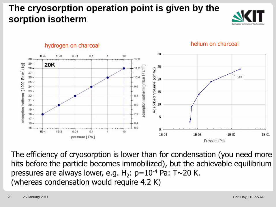
The efficiency of cryosorption is lower than for condensation (you need more hits before the particle becomes immobilized), but the achievable equilibrium pressures are always lower, e.g. H2: p=10-4 Pa: T~20 K.(whereas condensation would require 4.2 K)
0
5
10
15
20
25
30
1E-04 1E-03 1E-02 1E-01
Pressure (Pa)
Adsorb
ed V
olu
me (
cm
³/g)
10 K
hydrogen on charcoal helium on charcoal
The cryosorption operation point is given by the
sorption isotherm

Chr. Day, ITEP-VAC24 25 January 2011
Baffles + shields, pumping panels, and cryosupply
Tailor-madein-vessel cryopump,4.4 m x 1.5 m LHe @ 4.2 KS=400 m³/s (H2)
Tailor-madeITER Torus cryopump,With integrated valve.Valve DN 800, SCHe (4 bar) @ 4.2 KS=100 m³/s (all gases)
Commercial Refrigerator-Cryopump,Up to about 60 m³/s,DN 1200,Cryogen-free
Elementary Cryopump set-up

Chr. Day, ITEP-VAC25 25 January 2011
.min HQQQQ RadGFtot
)( 4
2
4
111212 TTACQ
211221
122112
)1()1(1
C
1. Solid heat conduction
2. Residual gas heat conduction
12QtQRad
3. Thermal radiation4. Phase change enthalpy
TALQF ·/
Source: Haefer
Cryopump elements given by cryogenics..

Chr. Day, ITEP-VAC26 25 January 2011
Cryopumps can in principle provide the maximum theoretical(´black hole´) pumping speed Sid, if the cold surfaces are installed
directly in the vacuum recipient (i.e. without any conductancelimiting flanges).However, the baffles which are needed due to cryogenic reasonsreduce the pumping speed to the practically achievable value.
The ideal pumping speed is reduced for a real pump- first by the limited transmission probability w of a particle onthe way from the vessel volume on the pumping surface - then by a non 100% sticking probability a of a particle at thepumping surface.
..But this has vacuumtechnical consequences

Chr. Day, ITEP-VAC27 25 January 2011
Classical cryopump design
1. 2. 3. 5.
4.
300K85K
7.
6.
Coated cryopanel (in ITER supplied with 4.35 K)
Thermal shields (in ITER supplied with 80 K) have to reconciletwo contradictory requirements: Minimize thermal radiation onto the panels but still provide sufficient conductance for the particles
Achieves a capture probability of ~ 20% (H2)
Chr. Day, ITEP-VAC28 25 January 2011
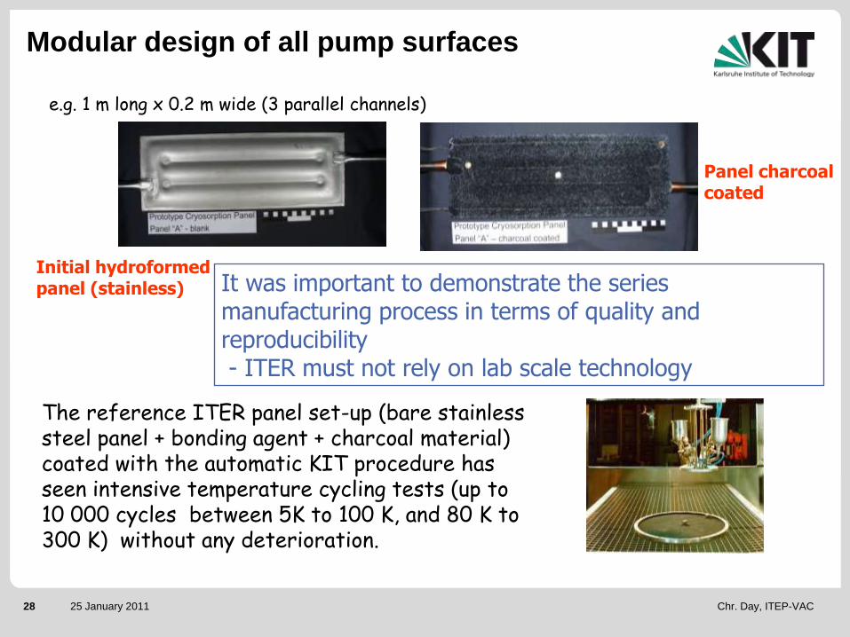
Initial hydroformed panel (stainless)
Panel charcoal coated
The reference ITER panel set-up (bare stainless steel panel + bonding agent + charcoal material) coated with the automatic KIT procedure has seen intensive temperature cycling tests (up to 10 000 cycles between 5K to 100 K, and 80 K to 300 K) without any deterioration.
e.g. 1 m long x 0.2 m wide (3 parallel channels)
It was important to demonstrate the series manufacturing process in terms of quality and reproducibility- ITER must not rely on lab scale technology
Modular design of all pump surfaces

Chr. Day, ITEP-VAC29 25 January 2011
Spin-off from fusion technology development:
Where you can find the KIT charcoal know-how
in various pump configurations
Chr. Day, ITEP-VAC30 25 January 2011
OutlineOutline
General introduction.
A few notes and basics of vacuum.
Fundamentals of cryopumps.
Detailed example: The ITER divertor and torus exhaust cryopumping system
How to calculate a flow under vacuum?
Experimental characterisation of a cryopump
The ITER neutral beam injection cryopumping system.
The other ITER high vacuum systems.
Roughing pumps.
Vacuum technology for DEMO / Fusion Power Plant.
Conclusions and outlook.

Chr. Day, ITEP-VAC31 25 January 2011
Torus cryopump
Scheme of the ITER torus exhaust system
Non-symmetric

Chr. Day, ITEP-VAC32 25 January 2011
The ITER lower port region
Ring with 54 divertor
cassettes
Cryopump1 Divertor
cassette
~ Rectangular pumping
channel
Laminar..........transitional……..…molecularKn~0.01and transitional Kn~500

Chr. Day, ITEP-VAC33 25 January 2011
The vacuum engineering task to solve
recipient
port vacuum pump
Correct description of the process Correct description of the system geometry
1. Process, difficult, input has to come from others.What is the mass flow that the machine defines, and which part of that has to be handled by the vacuum pumping system?
2. System geometry leads to complex flow conditions.What is the maximum possible mass flow through the port?
3. Correct pump choice.What mass flow can be accepted by the pumps?
pR pP

Chr. Day, ITEP-VAC34 25 January 2011
Pumping during burn phase
Maximum fuel throughput (DT) of up to 200 Pa m3/s at divertor pressure between 1 and 10 Pa, on top comes He, impurities etc…
Pumping during dwell phase
The dwell time between the 400 s burn pulses is only 1400 s to pump out the vacuum vessel and ducts (volume of about 1350 m³) at pressures lower than 0.5 mPa.
Extrapolated from JET: Q=3.5 Pam³/s (t/s)-0.73
Other pumping modes
Bakeout, glow discharge cleaning, EC/IC discharge cleaning (dirty)
ultimate pumpdown of the vessel, leak detection
Maximum pumping speed is paramount
Torus pump requirements

Chr. Day, ITEP-VAC35 25 January 2011
Calculation of vacuum flows in a wide range of the
Knudsen number requires to…
1. ….calculate flows in viscous regime, needs FEM modelling effort for ´unusual´ geometries.
2. ….calculate flows in free-molecular regime, needs Monte Carlo modelling effort for ´unusual´ geometries TPMC
3. …..calculate flows in the whole range of Knudsen numbers by the Boltzmann equations for some well defined (simple?) cases. To provide solutions of the Boltzmann equations for additional cases (3D, non-linearized) is ongoing, but a major effort.
4. ….calculate flows in the transitional range, needs Monte Carlo modelling effort with intermolecular collissions DSMC, Particle-in-cell
5. For applications most important: A network code for multi-channel systems.

Chr. Day, ITEP-VAC36 25 January 2011
Method Flow regime Validation What calculated Application
examples
MOVAK3D Test Particle
Monte Carlo
Free molecular With MOLFLOW
Fully validated
transmission probability;
Radiation heat load
All ITER cryopumps
ProVac3D Monte Carlo Free molecular,
extended to
collisional flows
With MOVAK3D and
MCGF in free
molecular;
Validation of
collisional flow
against DSMC
ongoing
3D density profiles;
non-isothermal system
with distributed gas
sources; non steady-
state problems
NBI systems
ITERVAC Semi-
Empirical,
Good as
design tool
All flow regimes With experiment
and kinetic theory
Validated for high
L/d; Improvement
currently ongoing
for small L/d
Flow rate
Pressure
Conductance
ITER divertor
DSMC transitional flow With experiment (e.g.
to get accomodation
coefficients right)
All macroscopic
quantities
ITER divertor and
gas injection system
These codes are developed by KIT + CFD for viscous flows
KIT fusion toolbox – Code Overview

Chr. Day, ITEP-VAC37 25 January 2011
How much is the flow to be pumped?
To
Pump
Plasma
Neutrals
Global flow chart of the divertor
ITER map of flows
Competitive pumping

Chr. Day, ITEP-VAC38 25 January 2011
ITERVAC provides the user with all tools to build up 2D networks
and calculates the mass flow through every channel depending on
the pressure of the gas source and inside the pumps.
Idea behind ITERVAC
gas sourcebinding node
channel
pump
Day et al., FEC 2006

Chr. Day, ITEP-VAC39 25 January 2011
Typical rarefied gas channel flow characteristics
1/Kn
Dim
ensio
nsle
ss flo
wra
te
Short circular tube with L/D=1, Nitrogen,ambient T (DSMC solutions by KIT).
Generalized Dimensionless solutions(Kinetic theory solutions by UTH, Greece)
Long channel: Fully developed flow Short channel: Developing flow
Varoutis, Naris, Hauer, Day, Valougeorgis, JVSTA 2009. Varoutis, Hauer, Day, Pantazis, Valougeorgis, in press, FED 2010

Chr. Day, ITEP-VAC40 25 January 2011
Dosing
Dome
Gas flow
Test
channel
Pumping
Dome
Turbo-
molecular
pumps
Experimental facility TRANSFLOW

Chr. Day, ITEP-VAC41 25 January 2011
High Kn numbers Complete failure of CFD
Circular channels
(even for slip flow boundary conditions)

Chr. Day, ITEP-VAC42 25 January 2011
Evolution of the final model by stepwise inclusion
of more and more divertor flow paths
Contains 1428Model ducts of different length and cross-section.
Calculation time is 2-8 h per point and up to 20 h per point in case of poor convergence (higher divertor pressures)
Source:Divertor
Sink:pumps
(55 m³/s per (pump + bellow)
Sink:plasma (black hole at 650 m²)

Chr. Day, ITEP-VAC43 25 January 2011
Input parameter: divertor pressure 1-10 Pa, deuterium (single gas), temperature 420 K
Additional effect of diagnostic cassettes (2008 design):He Conductance ~ 100 m³/s30 % pumped
Competitive pumping: plasma vs. pumps
2006 design: He Conductance ~ 30 m³/s, 2007 design: He Conductance ~ 60 m³/s,Variation of the divertor gaps,40% pumped
0
500
1000
1500
2000
2500
3000
3500
4000
4500
0 1 2 3 4 5 6 7 8 9 10
Divertor dome pressure (Pa)
Maxim
um
Th
rou
gh
pu
t (P
a m
³/s) Torus pumps Gap 10mm
Plasma Gap 10mm
Torus pumps Gap 20mm
Plasma Gap 20mm
Torus pumps (2006)
0
500
1000
1500
2000
2500
3000
3500
4000
4500
0 1 2 3 4 5 6 7 8 9 10
Divertor dome pressure (Pa)
Ma
xim
um
Th
rou
gh
pu
t (P
a m
³/s) Torus pumps
Plasma

Chr. Day, ITEP-VAC44 25 January 2011
0
1000
2000
3000
4000
5000
6000
7000
0 1 2 3 4 5 6 7 8 9 10
Divertor dome pressure (Pa)
Ma
xim
um
Th
rou
gh
pu
t (P
a m
³/s)
H2 torus pumps
H2 plasma
DT torus pumps
DT plasma
He tourus pumps
He plasma
H2
He
DT
Final results of the 2009 divertor pumping

Chr. Day, ITEP-VAC45 25 January 2011
0
50
100
150
200
250
300
0 20 40 60 80 100 120 140
Pumping speed of one pump (m³/s)
Ma
xim
um
Th
rou
gh
pu
t (P
a·m
³/s)
Reference
+ 1 cm
+ 2 cm
+ 3 cm
Protium
@ 2 Pa divertor pressure
Conclusion The design pumping speed
of the individual pump shall be 80 m³/s.
Target pumping speed =
Region 1:Throughput~ Pumping speed
Region 2: Conductance Limitation to Max Value

Chr. Day, ITEP-VAC46 25 January 2011
Requirements revisited
The effective molecular pumping speed of the (2009) divertor system on mass 4 (assumed pumping speed per (pump+bellow) is 55 m³/s) is consequently 1/(1/100)+1(4....8x55)) m³/s = 70....80 m³/s.
For mass 5 (50-50 DT) the values are: 60....70 m³/s.
For Helium (Pressure is expected to be between 0.25 Pa and 10 Pa):a) for an under-dome pressure in the range 4 - 10 Pa: throughput up to
120 Pa m³/s b) for an under-dome pressure < 4 Pa: throughput < 120 Pa m³/s and a
minimum pumping speed of 30 m³/s
For D-T (Pressure is expected to be in the range 1-10 Pa): a) for an under-dome pressure in the range 3 - 10 Pa: throughput up to
200 Pa m³/sb) for an under-dome pressure < 3 Pa: throughput < 200 Pa m³/s and
a minimum pumping speed of 50 m³/s

Chr. Day, ITEP-VAC47 25 January 2011
1. Pumping port size is limited Maximize pumping speed / Capture
probability at constant entrance area.
2. Worst case to design the cryosorbent panels reference design shall
include a pure helium/protium shot (which means 100% sorption pumping).
3. The composition of the gas mixture being pumped may vary significantly Minimize the dependency of pumping speed on gas
species.
4. The gas throughput is variable and must be controllable include an
inlet valve for control.
5. Compatibility with the operating conditions Magnetic and electric
fields, seismic, tritium-compatibility, Safety (Hydrogen explosion), Remote handling….
Torus pump design aspects for burn

Chr. Day, ITEP-VAC48 25 January 2011
Staggering interval of 150 s
p some 100 Pa
p = some kPa
p 10 Pa
p 10-6 Pa
p = 10-2 Pa max.
With this trick, we provide to the torus a quasi continuous pumping speed with batch regenerating cryopumps.
Operational scheme of the torus system(long pulse, max throughput)
Cryopump operational pattern is determined by explosion safety considerations, not by saturation effects of the sorbent.

Chr. Day, ITEP-VAC49 25 January 2011
Proper design needs a coherent set of
reliable (i.e. experimentally validated)
input parameters
1. Defined requirements (speeds, gas loads to be pumped, cooling concept).
2. Vacuum technological design: Cryopanel and thermal shield geometry. Optimisation by Monte Carlo calculations.
3. Cryogenic design: Heat loads, regeneration techniques.
4. Thermohydraulic design (cryogen flow pattern, transients, liquid cryogens vs. gaseous helium, pressure losses).
5. Mechanical design, piping, FEM analysis, EM forces, seismic
6. Safety (Hydrogen explosion).
7. Assembly and maintenance aspects.
8. Forepumping.
9. .....
Detailed pump design procedures

Chr. Day, ITEP-VAC50 25 January 2011
Stage I
1990-1995
Qualification of the sorbent
and the panel technique
Stage II
1995-2000
Test of complete
sorbent coated panels
Stage III
1999-2006
Investigation of the
scaled cryopump
Stage IV
2002-2006
Sorbent panels test
under tritium (JET)
1:1 scale prototypes and serial pumps
Development path towards the cryopumps

Chr. Day, ITEP-VAC51 25 January 2011
Heater
Test
Vessel
Process Control
2 KW
Refri-
300 K/450 K GHe
LN-Storage
Model Pump
Gas Dosage80K-System
Valve Box
gerator
80 K GHe
GN
LN
4,5 KSCHe
H
D
He
2
2 He Exhaustsystem
Test bed TIMO-2 @ KIT
TIMO is able to fully replicate ITER-relevant conditions in most aspects (cryogenic flow rates, gaseous flow rates and composition, cycling times) except of tritium.

Chr. Day, ITEP-VAC52 25 January 2011
The cryopump was a model pump (4 m² pumping surface)to investigate all relevant features and to validate in general the cryosorption pumping concept for ITER.
Tests with a model cryopump completed

Chr. Day, ITEP-VAC53 25 January 2011
Successful experiments in JET pumping tritiated gas (during the JET tritium experiment TTE and in a parametric programme in the JET Active Gas Handling System) and for determination of the residual tritium content.
0.4 m2 sorbent
area
Very successful quantitative T2
experience with ITER sorbent.
ITER Cryosorbent R&D
Complementary tritium tests at JET

Chr. Day, ITEP-VAC54 25 January 2011
Performance tests
Pumping speed tests for pure gases and relevant mixtures, at normal (4.5K) and elevated (up to 15K) temperature (relation S – p – Q – Pumped amount - Valve Position)
Capacity tests
(Poisoning) tests after accumulation of air-likes or water-likes (+ hydrocarbons, + radicals)
Cryogenic performance and fast regeneration tests
Safety tests
Sudden venting (LOVA triggered hydrogen release transients)
Water leaks
Mechanical tests
Cycling tests (30 000 full strokes)
Post operational inspection
Main test campaigns in TIMO

Chr. Day, ITEP-VAC55 25 January 2011
0
10
20
30
40
50
60
1E-4 1E-3 1E-2 1E-1 1E+0 1E+1
Pressure in pump (Pa) Inlet pressure (Pa)
Pum
pin
g s
peed (
m³/
s)
increasing
throughput
100% open
35%
25%
10%
Monte
CarloThe valve gives an additional degree of freedom in operation and allows to decouple the situation upstream the pump from the pumping situation inside.The pump is operated in transitional flow regime
It would be valuable for ITER to have a predictive tool, is doable by DSMC.
Exemplary TIMO results – Interrelation of pumping
speed, valve position and throughput
S = S (gas flow); not constant

Chr. Day, ITEP-VAC56 25 January 2011
Almost insensitive against the type of gas beingpumped, although bigdifferences in stickingcoefficients: a(He)=0.2 vs. a(D2)=0.9,achieved by Monte Carlobased interior design.
Exemplary TIMO results – Gas species
dependency
0
20
40
60
80
1E-3 1E-2 1E-1 1E+0 1E+1
Inlet Pressure (Pa)
Pum
pin
g S
peed
(m
³/s)
D2Base
D2Base/He
D2
He
D2Base
D2Base/He
D2
He
Valve Position 100% open
Valve Position 50% open
Chr. Day, ITEP-VAC57 25 January 2011
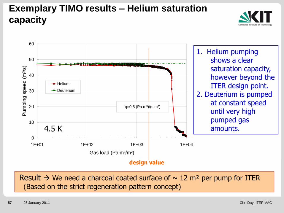
4.5 K
1. Helium pumping shows a clear saturation capacity, however beyond the ITER design point.
2. Deuterium is pumped at constant speed until very high pumped gas amounts.
design value
Exemplary TIMO results – Helium saturation
capacity
Result We need a charcoal coated surface of ~ 12 m² per pump for ITER
(Based on the strict regeneration pattern concept)
0
10
20
30
40
50
60
1E+01 1E+02 1E+03 1E+04
Gas load (Pa·m³/m²)
Pu
mp
ing
sp
ee
d (
m³/
s)
Helium
Deuterium
q=0.8 (Pa·m³)/(s·m²)

Chr. Day, ITEP-VAC58 25 January 2011
0
10
20
30
40
50
60
70
80
90
100
40 50 60 70 80 90 100 110
T (K)
Gas r
ele
ase (
% o
f pum
ped G
as)
T2
D2+T2
D2
H2
10 50 90 130 170 210 250 290
Panel Temperature (K)
0
20
40
60
80
100
Re
lea
se
d G
as (
%)
1. Partial regeneration every 600 s 2. Ambient regeneration less frequently
Condensed species evaporate and re-adsorb desorption rules.
Exemplary TIMO results – 3 stage regeneration
Conclude: Go for 90 K regeneration temperature, 100 K supply temperature
3. 470 K regeneration after incidents (e.g. water leaks)

Chr. Day, ITEP-VAC59 25 January 2011
90% D2 + 10% He, 4.5K, always identical (high) flowrate
Pumping speed tests with the cryopanels being pre-loaded with - water- light hydrocarbons (C1,2,3)- heavy hydrocarbons (C6, C8)- aromatics (benzene, xylene,
toluene)- alcohols (butanol)
No significant effect on
pumping speed measured
Exemplary TIMO results – No poisoning
Mixture pump tests after contamination
60
65
70
75
80
0 1000 2000 3000 4000 5000 6000
Gas load (Pa·m³/m²)
S (
m³/
s)
Reference curve
Octane
Hexane
Water

Chr. Day, ITEP-VAC60 25 January 2011
Exemplary TIMO results – LOVA on cryogen
Pressurisation with 50 Pa/s nitrogen, continued cooling,
testing together with CEA Grenoble
LOVA results in an averaged heat flux of 0.5 W/cm² (considerably lower than the ~ 4 W/cm² for non-insulated surfaces).

Chr. Day, ITEP-VAC61 25 January 2011
Exemplary TIMO results – Post-mortem inspection
(first opening after 6 years)
Check, especially of dynamic elements of the integral inlet valve, such as- bearings under vacuum (issue) - Valve and main seal- Spring disks (issue)- BellowsBut also:- Surface - Charcoal coating- etc

Chr. Day, ITEP-VAC62 25 January 2011
Duct double bellows
(compensation of torus
displacement)
Torus cryopump
Valve 80 K shield 4.5 K panels
Exhaust gas
from torus
Actuator
Part of the cryostat
Part of the duct
The pre-production torus cryopump design
8 such pumps on the torus:1:1 scale test in TIMO-2

Chr. Day, ITEP-VAC63 25 January 2011
Outline
General introduction.
A few notes and basics of vacuum.
Fundamentals of cryopumps.
Detailed example: The ITER divertor and torus exhaust cryopumping system
How to calculate a flow under vacuum?
Experimental characterisation of a cryopump
The ITER neutral beam injection cryopumping system.
The other ITER high vacuum systems.
Roughing pumps.
Vacuum technology for DEMO / Fusion Power Plant.
Conclusions.

Chr. Day, ITEP-VAC64 25 January 2011
Plasma heating at ITER
Functions of NBI: 1. Heating – 2. Diagnostics – 3. Current drive

Chr. Day, ITEP-VAC65 25 January 2011
NBI cryopumps at JET
As NBI applies very high gas throughputs, the NBI cryopumps in nuclear fusion are the largest worldwide. The JET system provides a pumping speed of 6000 m³/s.

Chr. Day, ITEP-VAC66 25 January 2011
Design process of a customized cryopump
1. Definition of requirements
(e.g. available space).
2. Gas distribution and flow
analysis defines the target
pumping speed.
3. Conceptual design=vacuum
design.
4. Detailed design.
5. Final / build-to-print design.

Chr. Day, ITEP-VAC67 25 January 2011
ITER in-situ NBI cryopump with distributed
sources
Ion Source with accelerator
Neutralizer
Residual Ion Dump
Calorimeter with “improved” water cooling supply
Cryopumps
Main Gas Source=
40 Pam³/s=
Additional Gas Source
5 Pam³/s=
Additional Gas Source
0.5 Pam³/s
=
16.5 MW hydrogen beam input to plasma
3.65m
3.48m
10m P=0.3 Pa
P=0.025 Pa
P=0.001 Pa

Chr. Day, ITEP-VAC68 25 January 2011
The capture coefficient concept
Incoming Gas flux (I)
Pumping of gas particles on cryogenic surfaces (P)
Cry
ogenic
pum
pin
g p
anels
Reflected (R)
Capture coefficientc=P/I
The capture coefficient describes the integral pump property, And can be used for model calculations at a stage where one does not yet know how to do the pump design at all.
AM
TRcScS id
2
A,c

Chr. Day, ITEP-VAC69 25 January 2011
X=0 X=1.6
Main sourceAdditional source Additional source
p1
p2
p3
2 baffles at end of N and RID, with varied capture coefficient
1.00E+17
1.00E+18
1.00E+19
1.00E+20
0 1 2 3 4 5 6 7 8 9 10
Distance X (m)
Den
sity
(1
/m^
3)
c=0.2 c=0.24 c=0.32 c=44
D2
Calculated axial gas profiles for varied c

Chr. Day, ITEP-VAC70 25 January 2011
Requested:
3.5·1018 /m³ = 0.025 Pa
Conclusion from the flow analysis
Conclusion: The cryopump must provide a capture coefficient of approx. 32 % for hydrogen, then the resulting gas profile along the beamline will work.This capture coefficient must be provided at a pressure of ~ 10-4 Pa(typical result of 3D MC radial profile calculations is ~ two orders of magnitude
lower in front of the cryopump)
Now, one can ´forget´ the system as such and concentrate on how to provide the given c in the given volume.

Chr. Day, ITEP-VAC71 25 January 2011
80 K
5.5 K Incoming Gas Flux
Transmission
Reflection
Sticking probability at charcoal: H2: 0.7D2: 0.9 - 0.95f (T, pumped amount),Geometry
Transmission probability of a chevron baffle only 0.2…0.25(Louvre not possible, due totoo high direct heat loads)
Classical conceptual cryopump design c = c (a, t)
The capture coefficient has two contributions:- the limited molecular transmission probability t of a particle on the way from the
vessel volume on the pumping surface
- the non 100% sticking probability a of a particle at the pumping surface.

Chr. Day, ITEP-VAC72 25 January 2011
c ~ 18% c ~ 28% c ~ 34%
Cold surfaces (5.5K)
Particle source
Radiation shielding (80K)
The neighbouring
pump unit protects
the cold surfaces
(5.5 K) from direct
radiation
Development of advanced configurationsC from Monte Carlo calculation

Chr. Day, ITEP-VAC73 25 January 2011
Comparison of design variants
Model 3JET like pump
Model 2KIT design
Model 1Classical cryopump
Capture coeff. (H2) 20% 33% 42%
Heat load to 4.5K circuits by thermal radiation related to the pumping surface (stand-by)
3.15 W/m2 3.63 W/m2 8.42 W/m2
Calculated with 3D Monte Carlo simulations

Chr. Day, ITEP-VAC74 25 January 2011
8x1m modules in series
1 module with 4 sections in parallel
1 section
The NBI cryopump so far

Chr. Day, ITEP-VAC75 25 January 2011
Neutral Beam Test Facility
at Padua - Italy
The main risk mitigation measure for resolving NB issues
The heart of the NBI activities will beat in Padova,
site of the MITICA test facility

Chr. Day, ITEP-VAC76 25 January 2011
Current status and outlook:
Detailed design activity programme for ITER / F4E
- We are charged to elaborate the detailed design (up to the level of Build-to-print manufacturing drawings, with CATIA v5) for the PPC and the HNB/MITICA cryopumps. lots of mechanical analysis (ANSYS), welding etc. Manufacturability and cost optimisation.
- These prototype pumps will then be manufactured and tested (the PPC in TIMO-2, the HNB in MITICA).
- Based on the results, we derive the series design.
- Then, the series pumps are built by (European) industry. TIMO-2 isavailable to acceptance check one or more of them.
Chr. Day, ITEP-VAC77 25 January 2011
Outline
General introduction.
A few notes and basics of vacuum.
Fundamentals of cryopumps.
Detailed example: The ITER divertor and torus exhaust cryopumping system
How to calculate a flow under vacuum?
Experimental characterisation of a cryopump
The ITER neutral beam injection cryopumping system.
The other ITER high vacuum systems.
Roughing pumps.
Vacuum technology for DEMO / Fusion Power Plant.
Conclusions.

Chr. Day, ITEP-VAC78 25 January 2011
- All of these vacuum systems do see tritium, so they haveto be made tritium compatible. They are categorized intwo classes, depending on permanent or ocassional
exposure to tritium.
- The standard pump type for these systems is aconventional Gifford McMahon based cryocooler cryopump(good compatibility with magnetic and electric fields, highpumping speeds). The compressor stations will probably be centralized.
- However, the pump must be modified towards tritiumsafety (only metal seals).In commercial pumps, the charcoal stages are employingepoxy as bonding agent.This has to be replaced with the ITER reference bonding(inorganic cement) and the ITER reference charcoal (with known behaviour against tritium).
Diagnostics and service vacuum systems

Chr. Day, ITEP-VAC79 25 January 2011
29m dia x 25.5 x 80mm, 304L, 0.5m clearance to bioshield
8500 m³ volume
Part of safety boundary 0.2 MPa internal design pressure.
Sub-assemblies in assembly Hall
Cryostat

Chr. Day, ITEP-VAC80 25 January 2011
It is foreseen to use the torus pump also as cryostat pump(just with closed housing to allow for intra-pump regeneration)!(Confirmative study to be done)
2 pumps in cryostat lower ports
The cryostat high vacuum system
Functional requirements:
Transient pump-down(closed cryostat volume) to 10-4 Pa and steady-state pumping of magnet coolant leak helium and outgassing species (of irradiated epoxy)

Chr. Day, ITEP-VAC81 25 January 2011
Outline
General introduction.
A few notes and basics of vacuum.
Fundamentals of cryopumps.
Detailed example: The ITER divertor and torus exhaust cryopumping system
How to calculate a flow under vacuum?
Experimental characterisation of a cryopump
The ITER neutral beam injection cryopumping system.
The other ITER high vacuum systems.
Roughing pumps.
Vacuum technology for DEMO / Fusion Power Plant.
Conclusions.

Chr. Day, ITEP-VAC82 25 January 2011
All high vacuum cryopump systems need a dedicatedforepumping train to provide for ~ 10 Pa cross-over pressure.
Regeneration of Torus Cryopumps (highly tritiated);
Regeneration of NBI Cryopumps (moderately tritiated);
Roughing of Service Vacuum System (slightly tritiated);
Regeneration of Cryostat Cryopumps (non/slightly tritiated);
Trains must discharge to processing systems (Tritium Plant, Vent/Atmosphere detritiation, Release point) appropriate to the tritium concentration in the gas stream;
Complex manifolding and changeover valves needed.
Forevacuum pump requirements (1)

Chr. Day, ITEP-VAC83 25 January 2011
In order to rough down to 10 Pa (cross-over to cryopump operation) :
- the torus within 1 day;- the cryostat within 4 days
(ITER asks for 1 day)- the NBI cryopump (by regeneration) within 8 min
the required maximal pumping speed (typically at ~100 Pa) of the roughing system is 6000 m3/h and for torus cryopumpregeneration within 2.5 min
3000 m3/h
Main clients of the roughing system: Torus (1350 m3) Cryostat (8400 m3) Torus cryopump (7.5…8.5 m3) NBI cryopump (200 m3)
Forevacuum pump requirements (2)
5 Main challenges of a roughing system with mechanical pumps:
Light gases are most difficult to pump (high backstreaming) This is especially complicated at the low pressure side The need to handle water moisture (condensation problems) Tritium compatibility Magnetic fields Very high pumping speeds

Chr. Day, ITEP-VAC84 25 January 2011
Issue of tritium compatibilityRequirements:
1. Secondary containment Enclosure in a glove box.
2. Extreme leak tightness against the outer world 10-9
Pa·m³/s to the outside
3. No elastomer seals allowed (O-rings), only metal seals (impact on sealing surface design, higher forces).
4. No cross-contamination between oil and process gas (tritium destroys the lubricant, and lubricant in tritium leads to increasing inventory due to isotope exchange) 10-7
Pa·m³/s shaft seal tightness (oil-process) no labyrinth
allowed.
5. Neglectable permeation rates of tritium through the housing stainless steel (no cast material), or coated surfaces.
Pumping of hydrogen for itself (high vacuum range) is alreadya different task!
Screening of the commercially available solutions

Chr. Day, ITEP-VAC85 25 January 2011
Available (low speed) T2-compatible pumps
Diaphragm pump(Metal bellows)
Scroll(Normetex)
Piston pump(Thales)
Turbopump @ JET(Varian)
These pumps are used as transfer pumps (i.e. not asking for low ultimate pressures) for radioactive gases in nuclear power stations and tritium plants.

Chr. Day, ITEP-VAC86 25 January 2011
There are ´dry´ large speed rotary pumps
…but not in the understanding of fusion
Roots pumpprinciple
Screw pumpprinciple
High amounts of purge gas needed, which increasethe gas load significantly

Chr. Day, ITEP-VAC87 25 January 2011
Current idea for ITER: Cryogenic forevacuum
The cryopump, after its regeneration, produces a higher pressure than in the case of continuous pumping, so that a (medium-size) tritium-compatible piston pump can be used as single mechanical pump.
Pearce, Baylor et al., SOFE 2009, San Diego, US.

Chr. Day, ITEP-VAC88 25 January 2011
European ITER concept
(pre procurement allocation)
based on mechanical pumping
4200m3/h
Roots
180m3/h Piston1200m3/h
Roots
US/ITER concept based on
cryogenic forevacuum pumping
(adaptation of JET AGHS
concept)
Various concepts on the market

Chr. Day, ITEP-VAC89 25 January 2011
Outline
General introduction.
A few notes and basics of vacuum.
Fundamentals of cryopumps.
Detailed example: The ITER divertor and torus exhaust cryopumping system
How to calculate a flow under vacuum?
Experimental characterisation of a cryopump
The ITER neutral beam injection cryopumping system.
The other ITER high vacuum systems.
Roughing pumps.
Vacuum technology for DEMO / Fusion Power Plant.
Conclusions.

Chr. Day, ITEP-VAC90 25 January 2011
An additional challenge..
- many km of welds- feedthroughs and electric breaks
- only very limited accessability
Detect a leak Locate a leak
Water leaks and helium leaks

Chr. Day, ITEP-VAC91 25 January 2011
Perspectives for DEMO
Mission 1 : Burning Plasmas-The development of a tunable torus exhaust vacuum system for plasma control, effective helium removal and disruption mitigation.
Mission 2: Reliability of tokamak operation-High availability of the vacuum pumping system.
Mission 4: Long Pulse and Steady-state Operation-The ITER cryogenic forevacuum pumping system is not an option for continuous operation (no 4 K needed for HTS magnets). Hence, a hybrid vacuum pumping system must be developed, which integrates a full tritium-compatible mechanical pumping solution with low ultimate pressures. This development means significant effort.
The associated R&D programme is in preparation under EFDA.
Chr. Day, ITEP-VAC92 25 January 2011
What do we learn from ITER for DEMO?
ITER pellet injection is slow no deep penetration, most probably not
an option for DEMO
ITER disruption mitigation Will hopefully demonstrate a viable
solution also for DEMO
ITER divertor radiative cooling gas injection We hope to learn from
ITER, but this has to be scaled up.
ITER high vacuum pumping works steady-state but would require
massive multi-cycle regenerations, hence a non-cryogenic solution would be very beneficial (High T superconductors, Helium shortness)
ITER rough vacuum pumping is not an option for DEMO (discontinuously, even more cryo consumption)

Chr. Day, ITEP-VAC93 25 January 2011
Necessary R&D routes towards DEMO
DEMO pellet injection will require deep fuelling compact toroids with
electromagnetic acceleration?
DEMO high vacuum pumping may be more advanced to fit steady-state/long pulse conditions (extend mechanical pumping down to lower ultimate pressures; alternative technologies with direct recyle of the unburnt fuel):
Cold turbopumps
Superpermeable membranes
Cryosorbents @ 20 K
DEMO rough vacuum pumping must be based on a reliable and versatile mechanical solution
DEMO requires real-time monitoring of tritiated substances (e.g. based on spectroscopy)

Chr. Day, ITEP-VAC94 25 January 2011
- We have had a look on the vacuum pumping systems of ITER. They are typical for any DT fusion experiment (where possible proceeding from the lessons learnt at JET).
- The large ITER high vacuum cryopumping systems (torus, cryostat, NBI) share a common modular approach of charcoal coated cryosorption panels, developed by KIT.
- The torus and cryostat vacuum pumping system is in a very advanced stage, testing a prototype and starting serial pump manufacture.
- The NBI vacuum system is in ongoing detailed design phase, but the test bed for the prototype is already under preparation.
- A broad data base for cryopumps has been set up with many parametricexp. data which allow to design customized cryopumps for ´any´application.
- A toolbox has been developed which provides all software means to do a rigorous design (heat loads, capture coefficients, etc…)
- The roughing pumping systems are still in a conceptual phase.
Conclusions

Chr. Day, ITEP-VAC95 25 January 2011 Int. School on Fusion Technologies 2010
- I want to encourage everyone to work in nuclear fusion.
- This holds especially for the vacuum systems field, where many challenging developments are still ongoing.
- The ITER vacuum systems are definitely the most complex in the world.
- Do not hesitate to contact me.
Interesting perspectives....
Our work is supported by EU under the EURATOM-KIT Association contract and F4E:
and the Helmholtz Gemeinschaft Deutscher Forschungszentren
Thank you for your attention!