vacuum insulation panels – exciting thermal properties
TRANSCRIPT

Vacuum Insulation Panels – Exciting Thermal Properties and
Most Challenging Applications
J.Fricke, H.Schwab and U.Heinemann
Bavarian Center for Applied Energy Research e.V. (ZAE Bayern), Am Hubland, 97074 Würzburg,
Germany, E-Mail: [email protected]
Abstract Vacuum insulation panels (VIPs) have a thermal resistance that is about a factor of 10 higher than that of equally thick
conventional polystyrene boards. VIPs nowadays mostly consist of a load-bearing kernel of fumed silica. The kernel is
evacuated to below 1 mbar and sealed in a high-barrier laminate which consists of several layers of Al-coated PE or
PET. The laminate is optimized for extremely low leakage rates for air and moisture and thus for a long service life,
which is required especially for building applications. The evacuated kernel has a thermal conductivity of about only
4·10-3
W/(m·K) at room temperature, which results mainly from solid thermal conduction along the tenuous silica
backbone. A U-value of 0.2 W/(m2·K) results from a thickness of 2 cm. Thus slim, yet highly insulating façade
constructions can be realized. As the kernel has nano-sized pores, the gaseous thermal conductivity becomes noticeable
only for pressures above 10 mbar. Only above 100 mbar the thermal conductivity doubles to about 8·10-3
W/(m·K);
such a pressure could occur after several decades of usage in a middle European climate. Our investigations revealed
that the pressure increase is due to water vapor permeating the laminate itself, and to N2 and O2, which tend to penetrate
the VIP via the sealed edges. An extremely important innovation is the integration of a thermo-sensor into the VIP to
non-destructively measure the thermal performance in situ. A successful “self-trial” was the integration of about 100
hand-made VIPs into the new ZAE-building in Würzburg. Afterwards several other buildings were super-insulated
using VIPs within a large joint R&D project initiated and coordinated by ZAE Bayern and funded by the Bavarian
Ministry of Economics in Munich. These VIPs were manufactured commercially and integrated into floorings, the
gable façade of an old building under protection, the roof and the facades of a terraced house as well as into an ultra-
low-energy “passive house” and the slim balustrade of a hospital. The thermal reliability of these constructions was
monitored using an infra-red camera.
1. Introduction Evacuated insulations are now known for more than a century. Evacuated “Dewars” were invented
by James Dewar in 1890 and “Thermos”-bottles were produced by the German company Thermos
GmbH. Such systems make use of a high vacuum (pressure below 10-4
mbar) to suppress gaseous
conduction and of highly reflecting walls (infrared emissivity typically 0.05) to reduce radiative
thermal transport. They are used in cryo technique and for domestic thermal storage and are either
made of thin glass or steel envelopes. Due to their cylindrical or spherical shape their walls are
load–bearing with respect to the atmospheric pressure of 105 N/m
2 (which corresponds to a load of
10 tons per m2).
Even better insulating properties can be obtained with evacuated foil insulations [1]. Here several
highly reflecting layers of crinkled or embossed metal foil (often separated by a thin fibrous layer)
or metal-coated polyimide foils are inserted into the evacuated spacing. Effective thermal
conductivities of below 10-4
W/(m·K) at room temperature can be obtained (see Fig.1).
If one wants to transfer the Dewar idea to flat panels, a load-bearing material has to be inserted
between the evacuated walls – otherwise they would collapse. Such vacuum insulation panels
(VIPs) have a history of several decades. Powder-filled VIPs were patented by L´Aire Liquide [2].
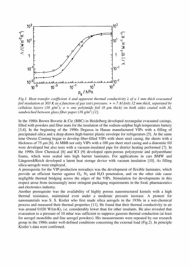
Fig.1. Heat transfer coefficient Λ and apparent thermal conductivity λ of a 1 mm thick evacuated
foil insulation at 303 K as a function of gas (air) pressure. + = 7 Al-foils 12 mm thick, separated by
cellulose layers (10 g/m2); o = one polyimide foil (8 µm thick) on both sides coated with Al,
sandwiched between glass fiber paper (16 g/m2) [1].
In the 1980s Brown Boverie & Cie (BBC) in Heidelberg developed rectangular evacuated casings,
filled with powders and fiber mats for the insulation of the sodium-sulphur high temperature battery
[3,4]. In the beginning of the 1990s Degussa in Hanau manufactured VIPs with a filling of
precipitated silica and a deep-drawn high-barrier plastic envelope for refrigerators [5]. At the same
time Owens Corning began to develop fiber-filled VIPs with sheet steel casing, the sheets with a
thickness of 75 µm [6]. At MBB not only VIPs with a 100 µm sheet steel casing and a diatomite fill
were developed but also tests with a vacuum-insulated pipe for district heating performed [7]. In
the 1990s Dow Chemical [8] and ICI [9] developed open-porous polystyrene and polyurethane
foams, which were sealed into high barrier laminates. For applications in cars BMW and
Längerer&Reich developed a latent heat storage device with vacuum insulation [10]. As filling
silica-aerogels were employed.
A prerequisite for the VIP-production nowadays was the development of flexible laminates, which
provide an efficient barrier against O2, N2 and H2O penetration, and on the other side cause
negligible thermal bridging across the edges of the VIPs. Stimulation for developments in this
respect arose from increasingly more stringent packaging requirements in the food, pharmaceutics
and electronics industry.
Another prerequisite was the availability of highly porous nanostructured kernels with a high
thermal resistance, maintained even under a moderate pressure increase. A pioneer for
nanomaterials was S. S. Kistler who first made silica aerogels in the 1930s in a wet-chemical
process and measured their thermal properties [11]. He found that their thermal conductivity in air
was around 0.020 W/(m·K), i.e. considerably lower than for other insulants. He also revealed that
evacuation to a pressure of 10 mbar was sufficient to suppress gaseous thermal conduction (at least
for aerogel monoliths and fine aerogel powders). His measurements were repeated by our research
group in the 1980s under well-defined conditions concerning the external load (Fig.2). In principle
Kistler´s data were confirmed.

Fig.2. Thermal conductivity of various silica powders as a function of gas (air) pressure at 300 K.
The external load onto the specimen is 1 bar [12]. Nanostructured silica aerogels have a lower
thermal conductivity than the other powders at all gas pressures. Perlite and diatomite have
conductivities above 0.060 W/(m·K) in air. The numbers in brackets are the densities of the
powders.
Though development activities for large scale production of aerogels were pursued by several large
chemical companies in the 1980s and 1990s [13,14], silica aerogels didn’t become available in
sufficiently large quantities.
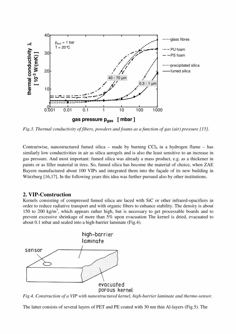
A systematic screening of powders, fibers and foams with respect to their insulating properties at
our Institute in Würzburg revealed (Fig.3), that load-bearing evacuated fibers provided the largest
thermal resistance among all insulating materials, however showed a doubling of conductivity,
once the gas pressure surpassed 1 mbar.
0.001 0.01 0.1 1 10 100 10000
10
20
30
40
fumed silica
glass fibres
precipitated silica
PS foam
PU foam
pext = 1 bar
T = 20°C
40 - 70 µm
0.3 - 1 µm
gas pressure pgas [ mbar ]
therm
al co
nd
ucti
vit
yλλ λλ
[ 10
-3 W
/(m
K)
]
Fig.3. Thermal conductivity of fibers, powders and foams as a function of gas (air) pressure [15].
Contrariwise, nanostructured fumed silica – made by burning CCl4 in a hydrogen flame – has
similarly low conductivities in air as silica aerogels and is also the least sensitive to an increase in
gas pressure. And most important: fumed silica was already a mass product, e.g. as a thickener in
paints or as filler material in tires. So, fumed silica has become the material of choice, when ZAE
Bayern manufactured about 100 VIPs and integrated them into the façade of its new building in
Würzburg [16,17]. In the following years this idea was further pursued also by other institutions.
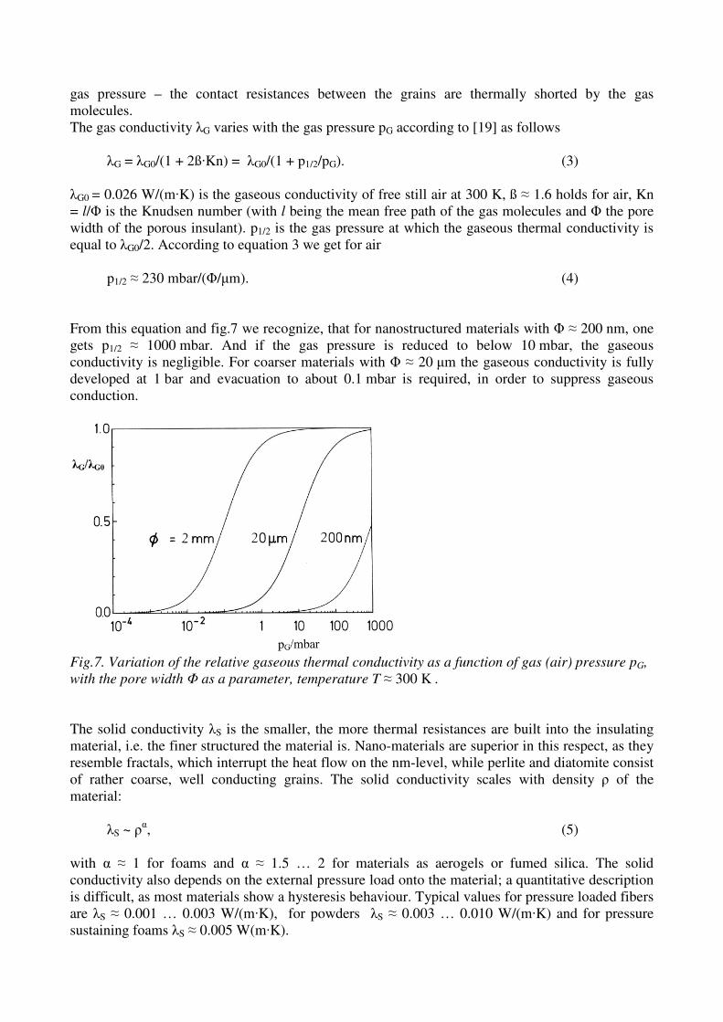
2. VIP-Construction Kernels consisting of compressed fumed silica are laced with SiC or other infrared-opacifiers in
order to reduce radiative transport and with organic fibers to enhance stability. The density is about
150 to 200 kg/m3, which appears rather high, but is necessary to get processable boards and to
prevent excessive shrinkage of more than 5% upon evacuation The kernel is dried, evacuated to
about 0.1 mbar and sealed into a high-barrier laminate (Fig.4).
Fig.4. Construction of a VIP with nanostructured kernel, high-barrier laminate and thermo-sensor.
The latter consists of several layers of PET and PE coated with 30 nm thin Al-layers (Fig.5). The

Fig.5. Typical high-barrier laminate for VIPs.
Al-layers serve as barriers for air and for water vapour. Because such thin metal layers have pin
holes, commonly two or three Al-layers are integrated into the laminate. Less often almost water
tight Al-foils with PE coating as sealing layer are employed – the 7 µm thick Al-layer causes
thermal bridging at the perimeter of the VIP.
Indispensable for quality control of the production process itself as well as for in-situ tests of the
thermal performance of the VIP on its way into a building is a thermo-sensor (Fig.6). An especially
sensitive sensor [18] uses a quasi-stationary method. Upon VIP production a 1 mm thick metal
plate (diameter about 30 mm), covered with a thin fleece layer, is sandwiched between kernel and
laminate. The fleece has a much coarser pore structure than the kernel and thus a noticeable
increase in gaseous thermal conductivity occurs even for a small increase in gas pressure (while the
gaseous conductivity of the kernel is still negligible). For measurements a hot sensor head is
pressed onto the sensor position. The sensor head gives off the more heat, the larger the
conductivity λF of the fleece is, i.e. the higher the gas pressure pG within the VIP is. If the λF(pG)
dependence is known from a calibration, the fumed silica curve in Fig.3 allows one to derive the
conductivity λK of the kernel from the gas pressure pG. Most easy is the data evaluation if the
temperature of the sensor head is kept constant by integrating an electrical heater into it. The
supplied electrical power Pel(t) is measured and plotted logarithmically versus t:
lnPel = const. - ξ·t, (1)
with ξ = (λF/dF)·AS/CS. Here dF is the thickness of the fleece, AS the sensor area and CS the heat
capacity of the sensor plate. If these three parameters are known, λF can be derived from ξ (the
slope) in the logarithmic plot. It is noteworthy, that the starting temperatures of the sensor and the
sensor head need not be known.
3. Thermal Transport in VIPs The kernel has to be optimized with respect to gaseous thermal conductivity λG, solid thermal
conductivity λS and radiative thermal conductivity λR, all three of which add up to the total thermal
conductivity λ. Also a coupling term λC has to be included:
λ = λG + λS + λR + λC. (2)
λC is negligible for foams with non-broken structure. Contrariwise it can be considerable at elevated
gas pressures, e.g. 0.020 to 0.030 W/(m·K) for powders consisting of hard grains (see fig.2,
examples perlite and diatomite). The coupling term becomes noticeable, when – upon increase of
gas pressure – the contact resistances between the grains are thermally shorted by the gas
molecules.
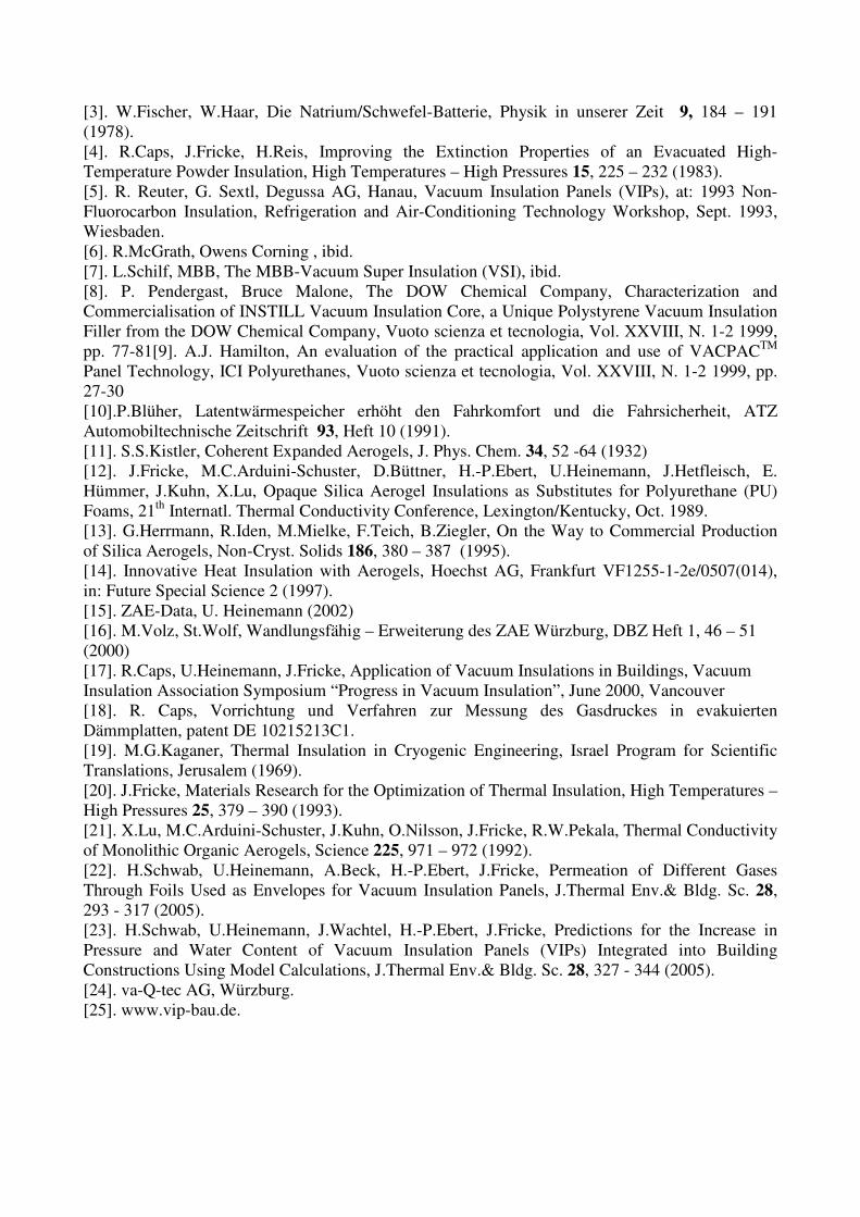
The gas conductivity λG varies with the gas pressure pG according to [19] as follows
λG = λG0/(1 + 2ß·Kn) = λG0/(1 + p1/2/pG). (3)
λG0 = 0.026 W/(m·K) is the gaseous conductivity of free still air at 300 K, ß ≈ 1.6 holds for air, Kn
= l/Φ is the Knudsen number (with l being the mean free path of the gas molecules and Φ the pore
width of the porous insulant). p1/2 is the gas pressure at which the gaseous thermal conductivity is
equal to λG0/2. According to equation 3 we get for air
p1/2 ≈ 230 mbar/(Φ/µm). (4)
From this equation and fig.7 we recognize, that for nanostructured materials with Φ ≈ 200 nm, one
gets p1/2 ≈ 1000 mbar. And if the gas pressure is reduced to below 10 mbar, the gaseous
conductivity is negligible. For coarser materials with Φ ≈ 20 µm the gaseous conductivity is fully
developed at 1 bar and evacuation to about 0.1 mbar is required, in order to suppress gaseous
conduction.
Fig.7. Variation of the relative gaseous thermal conductivity as a function of gas (air) pressure pG, with the pore width Φ as a parameter, temperature T ≈ 300 K .
The solid conductivity λS is the smaller, the more thermal resistances are built into the insulating
material, i.e. the finer structured the material is. Nano-materials are superior in this respect, as they
resemble fractals, which interrupt the heat flow on the nm-level, while perlite and diatomite consist
of rather coarse, well conducting grains. The solid conductivity scales with density ρ of the
material:
λS ~ ρα, (5)
with α ≈ 1 for foams and α ≈ 1.5 … 2 for materials as aerogels or fumed silica. The solid
conductivity also depends on the external pressure load onto the material; a quantitative description
is difficult, as most materials show a hysteresis behaviour. Typical values for pressure loaded fibers
are λS ≈ 0.001 … 0.003 W/(m·K), for powders λS ≈ 0.003 … 0.010 W/(m·K) and for pressure
sustaining foams λS ≈ 0.005 W(m·K).

In order to reduce the radiative thermal transport at a given temperature, as much absorbing and
scattering particles have to be integrated into the insulating material. As silica is a weak absorber in
the near infrared, an opacifier, e.g. SiC has to be added. Quantitatively the radiative thermal
conductivity is described by [20]
)(3
1632
r
rR
TE
Tn ⋅⋅=
σλ . (6)
Here n is the index of refraction, which can be approximated by n ≈ 1 for low density silica. σ =
5.67·10-8
W/(m2·K
4) is the Stefan-Boltzmann constant and Tr is an average temperature within the
insulant:
Tr3 = (T1 + T2)·(T1
2 + T2
2)/4. (7)
T1 and T2 are the temperatures of the VIP surfaces. E(Tr) is the extinction coefficient of the
insulating material, which is the reciprocal of the mean free path lph of the thermal photons and is
correlated with the density ρ and the mass specific extinction e(Tr) as follows
E(Tr) = e(Tr)·ρ = 1/lph. (8)
For opacified silica kernels one has lph ≈ 100 µm, which means, that VIPs with a thickness of 2 cm
are infrared-optically thick. e(Tr) can be calculated from the spectral mass specific extinction e(λ),
which is derived from infrared-optical extinction measurements within the wavelength range λ =
2 … 40 µm (see fig.8). By properly averaging e(λ) over the diffusing thermal spectrum at Tr
(“Rosseland”average), e(Tr) is obtained (fig.9).
Fig.8. Spectral mass specific extinction versus wavelength for pure silica aerogel (----), organic
resorcinol-formaldehyde aerogel ( — ) and for opacified silica with 5 % carbon black (…..)[21].

Fig.9. Mass specific extinction as a function of temperature of the materials in fig.8 [20].
According to equation 6 typical radiative conductivities of an opacified silica kernel at T = 300 K,
with a mass specific extinction e ≈ 50 … 60 m2/kg and a density ρ ≈ 150 kg/m
3 are λR ≈ 0.001
W/(m·K).
To wrap up the details in this section, one can expect total thermal conductivities of about 0.004
W/(m·K) for dried and evacuated opacified silica kernels, with contributions of 0.003 W/(m·K)
from solid conduction and 0.001 W/(m·K) from radiative transport.
4. Degradation of VIP´s performance with time High-barrier laminates, which enclose the silica kernel and are sealed along its perimeter are not
absolutely vacuum tight. We have to consider the penetration of N2 and O2 into the VIP, which - as
we shall see - occurs preferentially via the rim seal or point-like defects. Despite the Al-coatings
(shown in fig.5) in addition water permeation through the laminate itself leads to a pressure (and
mass) increase with time. The pressure increase can be measured using the so called foil lift-off
method [22]: The VIP is placed into a vacuum chamber. The pressure in the chamber is gradually
reduced. If the pressure in the chamber becomes smaller than the pressure within the VIP, the VIP-
cover lifts off the kernel, which can be recorded with a photoelectric sensor. The mass increase
with time can be determined by repeated weighing.
We have measured the pressure and the mass increase for fumed silica VIPs sized 10·10·1 cm3 and
20·20·1 cm3. Three different laminate types were employed. The VIPs were stored in air-
conditioned boxes over a period of about one year. In a dry climate linear increases of pressure with
time are observed (fig.10). (The linear increases ought to proceed for much longer times, as long as
the pressure inside the VIP is much smaller than the atmospheric pressure.) The increases are quite
different for the three envelope types. For the larger VIPs with doubled circumference (i.e. rim seal
length) and quadrupled volume for the relatively tight laminates AF and MF2 only one half of the
pressure increase is detected. This indicates, that the pressure increase is mainly caused by a length
related leakage, i.e. gas infusion via the rim seal. Also a strong dependence of the leakage rates on
temperature was observed (not shown here), which can be explained by a thermally activated
diffusion process and described by an Arrhenius-law.

Fig.10. Measured pressure increases over time for fumed silica VIPs of different sizes stored in
climate chambers at 45ºC and a water vapor pressure of 14 mbar, which corresponds to a relative
humidity of 15%. The envelope types were one Al-foil laminated with PE (AF) and two Al-coated
multilayer laminates (MF) [21].
Another set of VIPs was stored in boxes with a moist climate. The data from weighing are depicted
in fig.11. Linear increases in mass with time are observed. (We ought to note, that for very long
times the mass increase has to level off, because the driving force for the water infusion is the
difference between the vapour pressure outside and inside. For moist VIP kernels, which were
stored in a dry climate, even a mass decrease was observed.) Quite different mass increases occur
for the different types of envelopes. From the size dependence of the mass increases one can
conclude that the water vapour enters the VIP preferentially via the laminate itself.
Fig.11. Measured mass increases over time for fumed silica VIPs of different sizes stored in climate
chambers at 25ºC and a water vapour pressure of 24 mbar, which corresponds to a relative
humidity of 75 %. The envelopes were of the same type as in fig.10 [21].
The water, that has penetrated the VIP envelope, leads to a vapour pressure build-up, which is
determined by the sorption isotherm of the kernel material (fig.12). A water content of 1% by
weight thus leads to a relative humidity of about 10%, which corresponds to a water vapour
pressure of 2.3 mbar at 20ºC. The gaseous thermal conductivity of free water vapour is
0.016 W/(m·K) and the characteristic pressure p1/2 ≈ 120 mbar/(Φ/µm). From these data the

dependence of the gaseous thermal conductivity of water vapour in a fumed silica kernel, shown in
fig 13, can be calculated.
Fig.12. Sorption isotherms for fumed silica kernels at 23ºC. Plotted is the water content in mass %
of the dry kernel versus the relative vapour pressure [21].
Fig.13. Measured gaseous thermal conductivity of air ( — ) and calculated gaseous thermal
conductivity of water vapour ( ... ) within a fumed silica kernel. Water vapour has a smaller p1/2-
value than air, but a smaller λG0-value, thus the two curves show a cross-over. Due to condensation
of water vapour above about 20 mbar within the nanoporous silica only part of the λG(pG) - curve is
valid. .
Both, air and water vapour within the kernel contribute to the thermal conductivity. Our
investigations showed that for a typical middle European climate and the best available laminates a
pressure increase of below 1 mbar per year can be achieved. According to fig.3 the thermal
conductivity thus remains below about 0.006 W/(m·K) within a time span of 50 years, typical for
building applications. We also found, that a maximal water content of 3 to 7 mass% can be
expected in building applications in a typical middle European climate [23]. This would lead to a
maximal vapour pressure of about 15 mbar, corresponding to an additional water vapour induced
gaseous thermal conductivity of less than 0.002 W/(m·K) (see fig.13). Overall the thermal
conductivity of the VIP thus is expected to remain below 0.008 W/(m·K) even after 50 years of
usage.

An effect, which we only want to mention here, is the sudden displacement of adsorbed water
within the VIP kernel if, e. g. the warm and the cold side of a VIP are interchanged, or more
general, if non-stationary conditions are prevalent. The water displacement is correlated with a
significant transfer of latent heat within the kernel. Another effect, which is not discussed here, is
the increase in solid thermal conduction by the adsorbed water.
5. Applications VIPs have had a successful start in domestic appliances as well as in the logistics area, where
longtime temperature constancy is required. One example of the latter is a passive transport
container insulated with VIPs [24]. Measuring 1.4x1.1x1.6 m3 this container can maintain a
temperature of - 18ºC for 4 days or stay within a temperature span of +2ºC to +8ºC for 9 days. To
increase the heat capacity of the system, phase change materials are loaded into the container.
Building-related applications, which were pursued by ZAE Bayern are the integration of VIPs into
floorings, facades, roofs and slim balustrades (see fig. 14 through 17). Even an ultra-low energy
house (“Passive House”) was realized, using VIPs [25]. Details can be found under www.vip-
bau.de.
Fig.14: In 1998 first installation of VIPs in a building at the test façade of ZAE Bayern. For testing
purposes VIPs were integrated into the spacing of a jamb-crossbar construction.
Fig.15: Gable façade of an old building under protection during the installation (left) and after
renovation was finished (right). The shiny VIPs are in a rail system. The pale pink polystyrene
boards have just been mounted.

Fig.16: Photograph (left) of the new ultra-low energy timber building and the infrared image
(right) of the VIP insulated building envelope (architect: F. Lichtblau / Munich, Germany).
Fig.17: Jamb-crossbar construction made of aluminium: The vacuum-insulated facade-elements
during the installation (left) and outside view of the façade (right).
6. Outlook Without the tremendous progress in the quality of high-barrier laminates longtime applications of
VIPs in building technology would not be possible. Also the progress in understanding the thermal
transport in VIPs and the influence of gas and moisture intake as well as a stringent quality control
and the availability of simple and fast sensors have strengthened the confidence in the VIP as a
technical innovation.
A to-do-list for the future remain: develop even better laminates, which allow the use of cheaper
kernel materials; develop an RFID sensor, which can be read out without requiring a direct thermal
contact with the VIP surface; keep promoting the integration of VIPs into insulation systems for
protection and simpler application in the building process.
Literature [1]. K.G.Degen, S.Rossetto, R.Caps und J.Fricke, Evacuated Multilayer Foil Insulations –
Minimization of Heat Tranfer, in: Thermal Conductivity 22, Ed. Timothy W. Tong, Technomic
Publ. Co. Inc. Lancaster/Basel, 1994.
[2]. P.P.Gervais and D.Goumy, „Insulating Material with Low Thermal Conductivity, formed of a
Compacted Granular Structure“, US-Patent 4,159,359, June 26, 1979.
[3]. W.Fischer, W.Haar, Die Natrium/Schwefel-Batterie, Physik in unserer Zeit 9, 184 – 191
(1978).
[4]. R.Caps, J.Fricke, H.Reis, Improving the Extinction Properties of an Evacuated High-
Temperature Powder Insulation, High Temperatures – High Pressures 15, 225 – 232 (1983).
[5]. R. Reuter, G. Sextl, Degussa AG, Hanau, Vacuum Insulation Panels (VIPs), at: 1993 Non-
Fluorocarbon Insulation, Refrigeration and Air-Conditioning Technology Workshop, Sept. 1993,
Wiesbaden.
[6]. R.McGrath, Owens Corning , ibid.
[7]. L.Schilf, MBB, The MBB-Vacuum Super Insulation (VSI), ibid.
[8]. P. Pendergast, Bruce Malone, The DOW Chemical Company, Characterization and
Commercialisation of INSTILL Vacuum Insulation Core, a Unique Polystyrene Vacuum Insulation
Filler from the DOW Chemical Company, Vuoto scienza et tecnologia, Vol. XXVIII, N. 1-2 1999,
pp. 77-81[9]. A.J. Hamilton, An evaluation of the practical application and use of VACPACTM
Panel Technology, ICI Polyurethanes, Vuoto scienza et tecnologia, Vol. XXVIII, N. 1-2 1999, pp.
27-30
[10].P.Blüher, Latentwärmespeicher erhöht den Fahrkomfort und die Fahrsicherheit, ATZ
Automobiltechnische Zeitschrift 93, Heft 10 (1991).
[11]. S.S.Kistler, Coherent Expanded Aerogels, J. Phys. Chem. 34, 52 -64 (1932)
[12]. J.Fricke, M.C.Arduini-Schuster, D.Büttner, H.-P.Ebert, U.Heinemann, J.Hetfleisch, E.
Hümmer, J.Kuhn, X.Lu, Opaque Silica Aerogel Insulations as Substitutes for Polyurethane (PU)
Foams, 21th
Internatl. Thermal Conductivity Conference, Lexington/Kentucky, Oct. 1989.
[13]. G.Herrmann, R.Iden, M.Mielke, F.Teich, B.Ziegler, On the Way to Commercial Production
of Silica Aerogels, Non-Cryst. Solids 186, 380 – 387 (1995).
[14]. Innovative Heat Insulation with Aerogels, Hoechst AG, Frankfurt VF1255-1-2e/0507(014),
in: Future Special Science 2 (1997).
[15]. ZAE-Data, U. Heinemann (2002)
[16]. M.Volz, St.Wolf, Wandlungsfähig – Erweiterung des ZAE Würzburg, DBZ Heft 1, 46 – 51
(2000) [17]. R.Caps, U.Heinemann, J.Fricke, Application of Vacuum Insulations in Buildings, Vacuum
Insulation Association Symposium “Progress in Vacuum Insulation”, June 2000, Vancouver
[18]. R. Caps, Vorrichtung und Verfahren zur Messung des Gasdruckes in evakuierten
Dämmplatten, patent DE 10215213C1.
[19]. M.G.Kaganer, Thermal Insulation in Cryogenic Engineering, Israel Program for Scientific
Translations, Jerusalem (1969).
[20]. J.Fricke, Materials Research for the Optimization of Thermal Insulation, High Temperatures –
High Pressures 25, 379 – 390 (1993).
[21]. X.Lu, M.C.Arduini-Schuster, J.Kuhn, O.Nilsson, J.Fricke, R.W.Pekala, Thermal Conductivity
of Monolithic Organic Aerogels, Science 225, 971 – 972 (1992).
[22]. H.Schwab, U.Heinemann, A.Beck, H.-P.Ebert, J.Fricke, Permeation of Different Gases
Through Foils Used as Envelopes for Vacuum Insulation Panels, J.Thermal Env.& Bldg. Sc. 28,
293 - 317 (2005).
[23]. H.Schwab, U.Heinemann, J.Wachtel, H.-P.Ebert, J.Fricke, Predictions for the Increase in
Pressure and Water Content of Vacuum Insulation Panels (VIPs) Integrated into Building
Constructions Using Model Calculations, J.Thermal Env.& Bldg. Sc. 28, 327 - 344 (2005).
[24]. va-Q-tec AG, Würzburg.
[25]. www.vip-bau.de.