vacuum degassing of 500-pound melts for carbon …library.aimehq.org/library/books/electric furnace...
TRANSCRIPT

Vacuum Degassing of 500-Pound
Melts for Carbon Steel castings*
Abstract
THE effect of vacuum spray casting and of vacuum ladlc degassing of 500-lb melts of 0.30 pct carbon steel was studied by comparison of 12 by 12 by 4-in. slab castings, made from degassed and non- degassed metal, after sectioning and heat treatment of 6 by 6 by 4-in. samples.
Vacuum-cast slabs contained a fine, equiaxed macrostructurc and a charac- teristic solidification pattern in which the zone of the last-frozen porous mctal is displaced from thc center to a subsurface position in the castings.
Nondegassed slab castings contained central porosity when poured with met:il tapped above 1600°C (2912°F). Tensile bars from thc center of these castings gave reduced ductility and contained "fishcyes" on thcir fracturc surfaces. Raking a t 204°C (400°F) restored partial ductility. Pull ductility was restored by normalizing and tempering of 0.505-in. bars.
Vacuum-cast slabs ret:tined full duc- tility a t the center of the 4-in. sections provided that hydrogen content was reduced below 1.5 ppm. At higher hy- drogen contents, unlike the nondegassed castings, full ductility was restored by baking a t 204°C (400°F).
The improvement with respect to soundness obtained a t the center of
*Published by permission of the Director, Mines Branch, Department of Mines and Technical Surveys, Ottawa, Canada.
1
vacuum spray cast slabs was demon- strated by an increase of impact strength and by increased endurance limits for notchcd fatigue bars. The effectiveness of this method of casting was due both to, degassing and to the fact that the dry sand molds were held inside the pre- evacuated tank.
In the instance of ladle degassed melts, which were air pourcd into dry sand molds, improved tensile ductility was also obtained but without any corresponding inlprovemcnt of impact or notched-bar fatigue properties.
A correlation was observed between tapping temperature, gas porosity and mode of solidification, such that the loss of tensile ductility was greatest in the last-frozen metal of melts tapped a t the highest temperatures. The loss of duc- tility and incidence of fisheye fractures increased with riser hydrogen content and was more persistent in nondegassed than in degassed castings. In the absence of porosity, one nondegassed slab had full ductility despite a hydrogen content of 4.5 ppm. In porous areas, fisheye frac- tures were obtained a t hydrogen levels as low as 1.5 ppm.
Introduction
This report describes tests in which vacuum-degassed castings and ingots were prepared by the ladle or stream degassing methods. The degassed castings and' in-
50

Control of Nonmetallics in Steel for Castings 151
gots \sere comparcd with similar non- degassed standards.
One object of this series of tests mas to determine the amount of reduction i11 gas content obtained when 500-lb melts of carbon, low-alloy, and austenitic steels were spray-cast into molds, hcld illside the vacuum tank, i11 comparison with nondegassed and ladle degassed, air poured melts. Reduction in gas content due to degassing was dcterrnined on split heats and by comparison of test hcats with standard melts of similar composition.
Information was also sought about changes in the macrostructure and in the mechanical and physical propcrties of vacuum-cast stecls.
Another objective was the development of apparatus and techniques for vacuum casting of small laboratory mclts which would allow production of stcel com- parable in gas content with that produced by industrial vacuum casting processes.
The application of vacuum casting techniques to the production of large forging ingots has been studicd and is reported in detail in the literature.1 How- ever, much additional information is required about the application of vacuum casting and vacuum degassing techniqucs in the production of stcel castings.
Comparison of degassed and nonde- gassed 0.30 pct carbon steel was made on test castings having sections of 1 to 4 in., to determine the susceptibility of each section to gas porosity.
The criteria chosen for comparisoii of nondegasscd, vacuum spray cast and ladle degassed castings werc: tensile ductility, impact strength, and fatigue notch sensitivity. Thc center of the test bar gaugc lengths coincided with the center axis of the 4-in. cast sections.
Tests were also carried out to dctcr- mine the gas reduction and mechanical properties for steel that was dead melted,
1 References are on page 183.
dcgasscd, and poured into standard 1-in. keel block legs.
Equipment
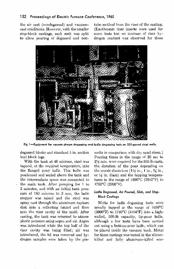
The vacuum degassing unit consists of a blower and rotary pump powered by 60-hp (overload) and 5-hp motors, rcspec- tively, pumpi~ig through a 10-in. vacuum valve and filtcr into a 100-cu-ft system. The system (empty) can be pumped to 500 microns Hg in 1.2 ininutcs and is designed for vacuum spray casting through an expciidable aluminum rupture disk. The unit is also suitable for ladlc degassing tests provided that a tempera- ture drop of 150°C (270°F) can be toler- ated. Thc pump and tank assembly are an I?. J. Stokes RiIodel 435 stream degassing unit.2 The vacuum system is illustrated in Fig 1.
Fig 2 illustrates the 350-lb (12 by 12 by 4-in.) slab casting, the 175-lb step- block casting having 1-in., 3-in., and 5-in. sections, and the 50-lb standard keel block casting,"aving four legs (6 by 1 by 1 in.).
Procedure
Vacuum Spray Cast Slabs and Step-Block
Castings
The vacuum spray castings and the step-block castings , mere prepared by placing a dry sand mold inside the tank. The tank was then pumpcd to about 40 microns,* which, under test conditions, corresponcled to an in-leak rate of about 1 micron per minutc, measured from 40 microns. Since the slab castings re- quired 350 lb of metal, with 500-lb melts it \\:as not possible to compare degassed and nondegassed slabs from the same heat. Consequently, individual castings from different melts were compared in
* All vacuum measurements refer to total gauge vacuum, mm Hg.
152 Proceedings of Electric Furnace Conference, 1960
the air cast (nondegassed) and vacuum- tube method from the riser of the casting. cast conditions. However, with the smaller (Exothermic riser inserts were used for step-block castings, each melt was split some tests but no increase of riser hy- to allow pouring of degassed and non- drogen content was observed for these
Fig 1-Equipment for vacuum stream degassing and ladle degassing tests on 500-pound steel melts.
degassed blocks and standard 1-in. section keel block legs.
With the tank a t 40 microns, steel was tapped, a t the required temperature, into the flanged pony ladle. This ladle was positioned and sealed above the tank and the intermediate space was connected to
. the main tank. After pumping for 1 to 2 minutes, and with an initial tank pres- sure of 180 microns to 2 mnl, the ladle stopper was raised and the steel was spray cast through the aluminum rupture disk into a collecting funnel and then into the riser cavity of the mold. After casting, the tank was returned to atmos- pheric pressure using argon and air. Argon was introduced while the top half of the riser cavity was being filled; air was introduced, the lid was removed and hy- drogen samples were taken by the pin-
melts in comparison with dry sandrisers.) Pouring times in the range of 30 sec to 236 min. were required for the 350-lb casts, the duration of the pour depending on the nozzle diameters (lJ6 in., 1 in., B/4 in., or 44 in. diam) and the tapping tempera- tures in the range of 1600°C (2912°F) to 1760°C (3200°F).
Ladle Degassed, Air Poured, Slab, and Step-
Block Castings
Melts for ladle degassing tests were usually tapped in the range of 1650°C (3000°F) to 1740°C (3164°F) into a high- walled, 500-lb capacity, lip-pour ladle, although a few tests have been carried out using a bottom-pour ladle, which can be placed inside the vacuum tank. Metal for these castings was tested in the silicon- killed and fully aluminum-killed con-

Control of Nonmetaltics in Steel for Castings 153
Fig 2-Three types of castings. a. 350-lb slab casting with risers. b. 175-lb step-block casting. c. Standard 50-lb, four-legged keel bl~ck.
154 Proceedings of Electric Furnace Conference, 1960
ditions. When minimum hydrogen con- tent was requircd, the reduced basic furnace slag was partially removed by a furnace slagoff before tapping or by a pit slagoff after tapping. For other process studics, such as desulphurizution, decar- burizntion, and dcoxidation, the furnace slag was tapped, with the mctal, into thc trcatment ladlc.
Hydrogcn pin-tubc sa~nples werc taken after the boil, a t tap, from the ladle after tapping and from the risers of the air cast and degasscd test castings. Oxygcn and nitrogen dcterminations wcre made on samples cut from the casting risers and from the kecl block lcgs cast before and after degassing.
Aftcr tapping, the ladle was placcd insidc the tank. The pumps reduccd the pressure to about 15 mm in 15 scc. During pumpdown, brcaking up of any frozen slag occurrcd and a vigorous boil com- mcnccd, which, in silicon-killed heats was equal to thc dcpth of the metal held in the ladle. Thc violence of thc boil cle- pcnded on the deoxitlation practice, the tapping temperature, and the quantity of furnace slag present. After the vigorous initial boil and a high initial pressure of about 15 mm, the prcssure fell rapidly to the range 600 microns to 4 mm. Several fully killcd mclts were dcgasscd a t total pressures of the order of 600 microns. The duration of thc ladle dcgassing tcsts was 1 to 4 min. Pressures during ladle treat- ment of silicon-killed melts,' or during tests where the furnace slag was not re- moved, were higher than those obtained with fully killed metal or when most of the slag was removed prior to treatment.
During ladle degassing of 500-lb mclts tapped in the range 1675°C (3050°F) to 1725°C (3140°F), a temperature drop of 100°C (180°F) to 150°C (270°F) occurred in the 5 to 8 min. of handling and treatment time. Thc time available for ladle degassing was limited by the
temperature drop that could be tolerated, consequently the boil resulting from secondary decarburization a t reduced pressures was allowed to continue for only 1 to 4 min. before the tank was returned to atmospheric pressure.
As soon as the tank was returned to atmospheric pressure, the ladle was re- moved, the castings were poured in air, and hydrogen pin-tube samples were obtaincd from the risers and from the stream of the bottom-pour ladle.
For several tests, metal tapped a t 1700°C (3092°F) was held outside the tank until i t had cooled to 1525°C (2777°F) or 1550°C (2522°F) and was then cast to allow comparison of non- degassed and degassed steel castings that had been tapped and poured a t the same
Most of the castings were poured into dry sand (baked) molds, but in one scries of tcsts, two slab castings and two step- blocks were pourcd into green sand molds (3 pct watcr by weight).
The pouring temperature for the ladle degassed castings varied between 1500°C (2732°F) and 1575°C (2867°F) corre- sponding to tapping temperatures of 1650°C (3000°F) and 1740°C (3164°F).
In another series of tests, exothermic sleeve inserts were used in the risers to determine whether any improvement in the soundness or gas content of the cast- ings could be obtained by this method of inducing directional solidification.
ladle to ladle Degassing, and Air Pouring
The ladle to ladle degassing and air pouring method, used commercially for the production of castings from degassed steel, was the most difficult method for small melts because of the drop in tem-
' perature of about 200°C (360°F), which resulted in pouring temperatures of the order of 1500°C (2732°F) from metal
: tapped a t 1700°C (3092°F). Effective

Control of Nonrnetallics in Steel for Castings 155
reduction in gas content was acllicved holvever by this method, ~vhich combined the spray degassing and ladle degassing techniques.
Method of Testing
The 12 by 12 by 4-in. slab castings mere cut into four blocks about 6 by 6 by 4-in. each. An %-in. vcrtical section and two 34-in. horizontal slices wcre cut a t the center axis of the slab. These slices were radiographed and were then deep-ctched for 30 min. The two bottom (6 by 6 by 4-in.) blocks were normalized by holding a t 900°C (1650°F) for 2 hr, followed by air cooling, and were tempcred for 2 hr a t 650°C (1200°F) and wcre air cooled. One bottom block mas used to provide three tensile bars a t the center of the 4-in. section and a set of 25 Charpy V-notch impact bars with the notches a t the center of the slab. R. R. Rloore fatigue bars and tensile bars 1 in. belolv the casting surface were cut from the other bottom block.
Tensile bars, taken a t the 1-in. position of the slab, were tested in the bakcd 70 hr condition 204°C (400°F), and unbaked condition.
Tensile ductility, impact strength, and fatigue notch sensitivity were also meas- ured on standard 1-in. section kecl block legs for comparison with the results ob- tained on the sectioned 4-in. slab castings.
Sectioning and tcsting of the stcp-block castings was done by cutting off the 1-in. bottom section and tiking a 1-in. slice, which includcd the center metal from the 3-in. and 5-in. sections. Nondegassed and ladle degassed representative castings in
\ this group were selected, and one of the cut surfaces, adjacent to the centcr slice, was surface-ground and deep-etched.
All of the standard 1-in. keel block legs poured before and after degassing were normalized and tempered prior to testing.
Results
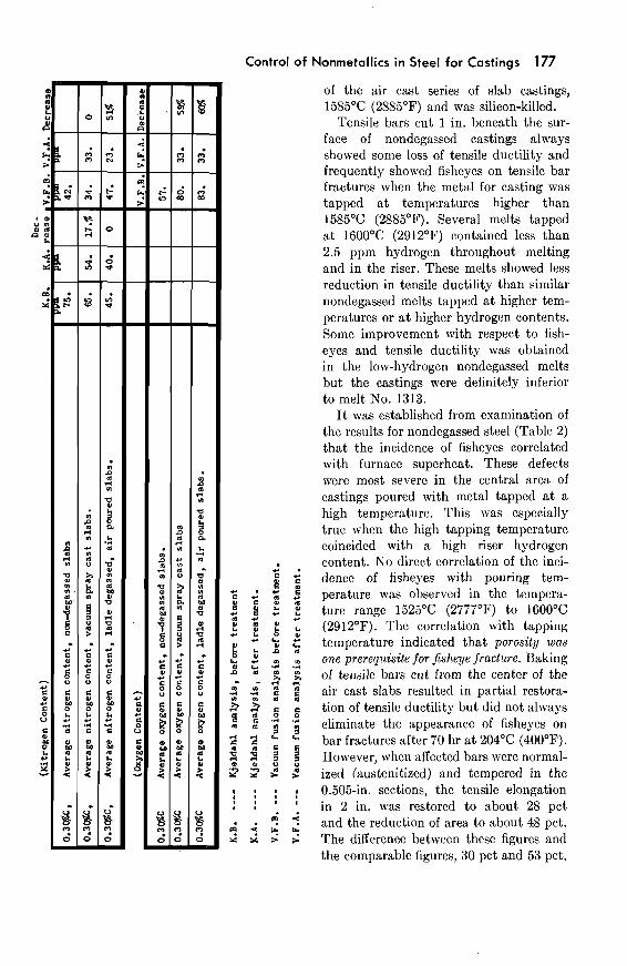
Thc chcmical composition, gas content, impact strcngth, unnotchcd and notched R. R. i\/loorc endurance limits and clean- ness ratings for nondegassed slabs are given in Table 1.
The hydrogen contents were mcasured by hot extraction analysis of pin-tubc samples takcn from the furnace bath, after the boil and immediately bcforc tapping. Pin-tube samples were also taken from the ladle after tapping and from the risers of the castings. Nitrogen ancl oxygcn contcnts werc obtained by vacuum fusion analyses. The nitrogen analyses were also determincd by the Kjeldahl wet method.
Charpy V-notch impact bars, cut from the ccnter of the slabs with thcir notchcs a t the center axis of the casting, were brokcn a t 93°C (200°F), 27°C (80°F), 4OC (40°F), - 18°C (0°F) and a t - 40°C ( - 40°F).
Thc unnotched and notched R. R. RIoore fatigue endurance limits wcre ob- tained on mctal cut from the center of thc slabs. The strength rcduction factor was obtained for each slab. The castings werc rated for cleanness on thc basis of cxami- nation of dcep-etchcd and radiographed $4-in. slices.
The cleanness rating assigned was: (1) excellent, nothing visible on the macro- etch or radiograph; (2) good, nothing visible on the macroetch but traccs of porosity visible on the radiograph; (3) jair, some visible porosity on the macro- etch and definite indication of porosity in the radiograph; (4) dirty, contains visible slag or evidcnce of inclusions ancl - severe porosity on the radiograph.
The results of tensile tests on 1-in. standard kecl block legs, normalized and tempered in the 1-in. sections are shown in column A, Table 2 for bars cast from the melts used for the nondegasscd slab castings. Colun~ns B, C, and Dl Table 2,

TABLE 1
Non-Depassed Dry Sand Slab Castinus Chemical and Gas Composition, Impact Strength, Fndurance Limits and Cleanness Rating
Melts 1299 and 1401 a r e not included i n the averaged fatigue resul t s - Melt 1396 i s omittea r r m a l l averages. I Double s lag basic melts having higher than normal s i l icon contents M 0.53% carbon content,. - acid melt
A h l Non-degassed s t ep block - a l l other melts wen, 1 U 2 x L in. slab castings K-Kjeldahl analysis . '
VF-Vacuum Fusion analysis
Melt NO.
1120
f1286
f1299
1313
1332
1336
1389
1373
M 3 9 6
1401
i lk07
m 4 2 8
,Avera~es
Endurance Limits and Strength
Hydrogen Nitrogen Charpy V Notch Reduction Factors Chemical Composition
(Per Cent)
fi ur(
$2 2.5
3.1
- 2.5
- 1.6
2.3
2.1
0.7
1.8
2.2
- 2.3
,"$
3.5
5.4
- 2.4
1.9
1.6
3.2
2.2
0.5
2.0
2.0
- 2.7
C
-28
.29
.27
.30
.31
.33
.31
.32
.53
.32
. 3 1 . 8 0
.304
Content and Impact Strength .kosi kpsi ( ~ m ) %gen ( f t - l b ) u u
, t Contents w u u c6 T C w c 4- U '
Per Cent Ye,. 224 Xi 2% S i
-46
.83
.77
.23
.17
.27
.35
.33
.96
.38
.71
k4n
.64
.98
.95
.66
.68
.69
.90
.87
.78
.75
. 2 5 . 8 0 . 4 2
3.7
5.1
- 3.4
1.6
2.0
3.5
2.4
0.6
1.9
2.5
- 2.9
S
,020
,016
.024
.C25
.020
.016
,015
,C29
.024
.013
.022
4.3
6.3
- 4.5
2.1
2.5
4.2
4.4
2.7
3.6
3.3
- 3.9
P
,011
.017..020
,019
.033
,026
,022
.030
,032
$23
.030
.C25
. 023 .15
At
"
"
"
"
"
"
"
"
" "
"
Cr
- .13
.09
.14
.14
.14
.24
.26
.12
.22
.U,
,011
.010
.010
.006
,007
.007
.036
.006
,004
,006
,006
.W75
.009
.007
.007
.002
,032
.00l
,002
,003
.003
.005
-
.0042
,039
,006
.006
,006
,004
,007
,004
.004
.006
.005
- - - - -
,0057
72.
- 71.
67.
67.
65.
66.
64.
14.
U.
-
65.
34.
27.
32.
24.
2R.
28.
21.
19.
5.
17.
26.
21.
- 26.
17.
18.
15.
13.
14.
. 4.
10.
- -
17.
9.
- 9.
7.
6.
7.
6.
6.
3.
6.
- - 7.
4.
3.
3.
3.
3.
4.
4.
3.
3.
3.
29.
35.
33.
26.
27.
34.
35.
39.
30.
- - - 30.6
22.
21.
29.
18.
21.
23.
23.
27.
23.
-
21.4
1.32
- 3 .
1.67
1.74
1.45
1.29
1.48
1.52
1.44
1.70
- - 1.U
3.
3.
1.
2.
3.
1.5
1.
1.5
1.
1.5

IDLE 2
Hon-Ds~aaacd Dry S a d Slab C a s t i w s
T e r v i l s R o p r t i o s , Pishaye R a c t u r e s and Melt Data
n
7
0 2. z P !! P - -. n u -. a
'D -I.
4 n
Column A - 0.505 t e n s i l e ba r s cu t from 1 in. kee l black l egs 2 8 - " " 1 i n . b e l m surface of sl:b cas t ings - (unbaked) =. C - a n ,, ,, ,, l in. ,, ,, rn u - (baked 70 hr a t 2w.c - LOO-F) a D - " " " I ro~n cen t re of slabs.
A - 11. H - CaMnSl. N i l - s i l i c o n - k i l l e d % .. Helt 1596 was not included i n the averaged r e s u l t s .
Tens i l e bars i n Col- A were soaked 30 minutes a t 900.C (1650aF), rere air-cooled ard t cmprad 2 h r a t 650°C (1200.F); as 1 in . x 1 in. x 6 in . scction?l. -. Tens i l e ba r s i n Col-s 8, C and D were soaked 2 hr a t 900.C (165OSF), were a i r -cca led a d t empred 2 hr st 650.C (la00.F); as 6 i n . x 6 in . x L in . sections. U
V

158 Proceedings of Electric Furnace Conference, 1960
show the results of tensile tests on non- degassed slabs a t the 1-in. position, un- baked; a t the 1-in. position, baked and a t the bottom center of the slabs, unbaked, respectively.
Loss of tensile ductility was apparent in the slab casting. Frequently fisheyes were observed on the fracture surfaces of tensile bars. The incidence of fisheye fracture is shown in Table 2 for the tensile bars corresponding to columns A, B; C, and D. Tensile bars exhibiting brittle, fisheye fractures arc represented by filled squares in Table 2.
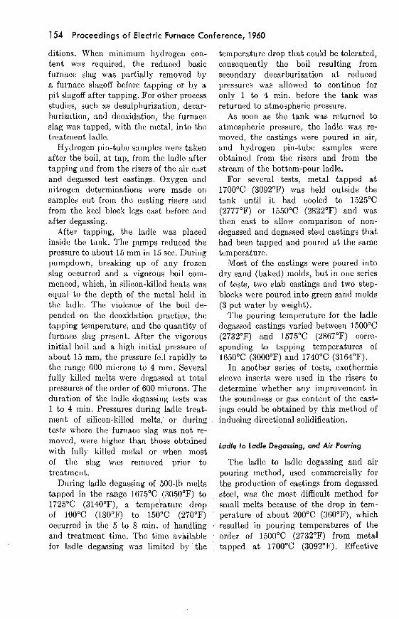
The appearance of deep-etched (30 min.) macroetch sections through four nondegassed slab castings, Nos. 1286, 1332, 1393, and 1313, are shown in Fig 3. Melt No. 1286 represents the worst con- dition of loss of tensile ductility and fish- eye fracture. Melt No. 1313 represents the best condition obtained without vacuum treatment. This melt was silicon- killed, tapped a t 1585°C (2885°F) and was poured a t 1525°C (2777°F). Despite a riser hydrogen content of 4.5 ppm, full ductility was obtained a t the center of this slab.
The macrosections shown in Fig 3 illus- trate the typical columnar and equiaxed structure of as-cast air poured slab castings. Melt No. 1313, having a sound radiograph section, was the only non- degassed slab that gave full tensile duc- tility, without baking, in tensile bars cut from the bottom, center, and mid- point of the 4-in. section. Melt No. 1286, containing evidence of gas porosity in the radiograph section, was slightly worse than most of the nondegassed slabs with respect to loss of tensile ductility and the presence of fisheyes. (Melts Nos. 1286 and 1299, in addition to evidence of porosity, contained higher than average silicon contents.) Thus, while fisheyes were largest in melts Nos. 1286 and 1299, tensile bars from the center of all of the nondegassed slabs, except No. 1313, con-
tained fisheyes and showcd traces of gas porosity a t the center of the radiograph slices. The melts were tapped a t tem- peratures from 1600°C (2912°F) to 1740°C (3164°F) except for melt No. 1313, which was tapped a t 1585°C (2885°F).
Melts Nos. 1332, 1336, 1393, 1401, and 1407 were melted with the hydrogen content of the bath below 2.5 p p ~ n throughout the melt but were tapped a t temperatures higher than 1585°C (2885°F). These castings all suffered from loss of tensile ductility and the presence of fisheyes, despite use of exothermic riser inserts in two instances.
Tensile bars from all locations of melt No. 1286 exhibited fisheye defects on these fracture surfaces. After baking 70 hr a t 204°C (400°F) some tensile ductility was .restored. Full tensile ductility was restored after the bars were normalized (austcnitized) and tempered iu the 0.505- in. bar section. .Material for bars from melt No. 1286 was stored a t ambient temperature for one year as 6 by 6 by 4- in. blocks and from these 0.505-in. tensile bars were machined and stored for a further 6 months period. When broken, bars corresponding to a position adjacent to the original surface of the casting were ductile but loss of tensile ductility and fisheyes were still obtained in all bars corresponding to the center position and in thc two bars adjacent to the cut sur- faces made during sectioning of the cast- ing. The unbaked bars, despite storage, retained a memory of the hydrogen distri- bution present a t the end of solidification.
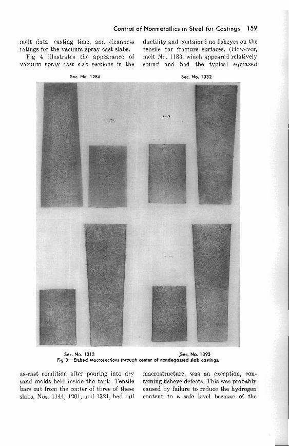
Table 3 lists the chcmical composition, gas content, casting pressure, impact strength and endurance limits for vacuum spray cast slabs. Table 4 can be com- pared with Table 2, and contains thc results of tensile tests on 1-in. standard kcel block legs, a t the 1-in. casting posi- tion, baked and unbaked, and a t the center of the slabs. This table also shows the location of fisheye fractures and gives
Control of Nonrnetallics i n Steel f o r Castings 159
melt data, casting time, a.nd cleanness ratings for the vacuum spray cast slabs.
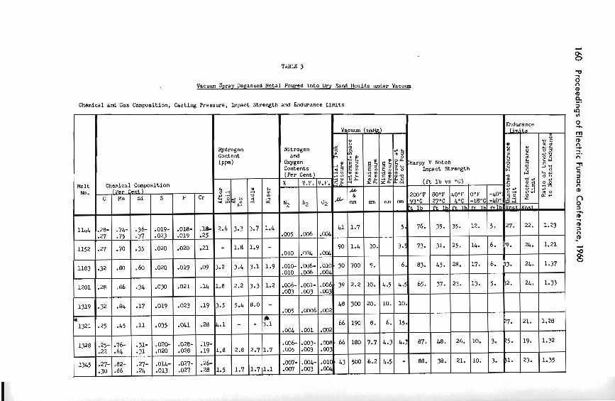
Fig 4 illustrates the appearance of vacuum spray cast slab sections in the
Sac. No. 1286
ductility and contained no fisheyes on the tensile bar fracture surfaces. (However, melt No. 1183, which appeared relatively sound a.nd had the typical equiaxed
Sec. No. 1332
Sec. No. 1313 ,Set. No. 1393 Fig 3 4 t c h e d rnocrcnecfions through center of nondegassed slob castings.
as-csst condition after pouring into dry macrostructure, was an exception, con- sand molds held inside the tank. Tensile taining fisheye dcfccts. This was probably bars cut from the center of three of these caused by failure to reduce the hydrogen slabs, Nos. 1144, 1201, and 1321, had full content to a safe level because of the
Vacuum Spray Ds~assed Metal Poured into U r y Sand I4oulds under Vacum
Chbnical and Gas Composition, Casting Ressure, Impact Strength and 6ndurance Limits
Melt No.
1144
1152
1183
1201
1319
* 1321
1328
1345
Chemical Composition
Hydrogen Content (PW)
b A
5 ZS --
22.
- 3.2
1.8
3.5
4.1
1.8
1.5
-018- .019
.020
.019
.O21
.023
.OW
-028- .028
.027-
.027
.28-
.27
.27
.32
.28
.32
.25
.25-
.22
.27-
.30
Cr
.I.$- -25
.21
.Og
.U
.19
.28
.19- -19
-26- .28
Cent ) si
-36- .37
.35
.60
.?I+
-17
1
-31- .31
.27-
.24
I Per nn
.74-
.75
.70
-80
.86
.84
.L5
. 7 6
.64
-82- .86
Vacuum
8 Nitrogen 2 ,a
and c . O
Ween w % 5
c a
33.
1.8 -
.019-
.023
.020
.020
.C30
.019
0
.O2&
.020
.OU-
.Ol3
(raaHk)
ij! ,E
10.
9.
10.
20.
8.
7.7
6.2
:harpy v Notch Impact Strength
a r(
i
3.7
1.9
Contents
Endurance
B
1 - 0
2M)"F 93.C r t lb
76.
73.
g $ z a b '"
1 ~ .
41
48
66
43
I. 0
2
1.4
-
'5 a 5 '$ 3 3
rt&&&&n-i
27.
9.
2 2 E m g ' &
& mm
1.7
9 0 l . L
700
2.2
300
190
180
500
1.9
1.2
- IC 3.1
1.7
1.1
v . F . ) v . F . s $ z
d2
.001r
:cq,
.OOL
.ow
-002
.002
JXM.66 .W?
.010. -001,
(Per K
N2
.a35
.OlO
.010
.003
.005
.oQL
,005
.W-
.W
83.
65.
87.
88.
3.4
2.2
5.4
-
2.8
1.7
Cent
N2
.006
,004
.OlC-.C06-.010~30 .006
.W6-.001-.006.39 . a 3
.0006
.w1 .CQ6-.003-
.OO3
.W4- .003
e.2 i3
22. ---
24.
24.
24.
21.
19.
23-
( e r a r o c , .
BO'F 27.C ft
35.
31.
3.1
3.3
8.0
-
2.7
1.7
,z i ~ c b 5 l
4.5
10.
6.
4.3
4.5
r ) a,. 5 Q
1.23
1.21
i.37
1-33
1.28
1.9
1.35
40.F 4.C
&& Ih
35.
25.
OaF -18-C rt lh
12.
14.
%
mn
5 .
3.5
6.
4.5
10.
15.
L.?
-
L5.
37.
48.
38.
-LOE -Lo*,
5 .
6.
I 28.
23.
26.
21.
17.
13.
10.
10.
6 .
5 .
3.
3.
33.
32.
27.
25.
1.
Control of Nonrnetallics in Steel for Castings 161
rapid pouring rate, 21 sec for 500-lb of steel.)
The macrostructures of the degassed, as-cast sections were refined and equiaxed in comparison with corresponding macro- etched slices from nondegassed slabs. Comparison of radiographs of nonde- gassed and vacuum spray cast slices indi- cates a tendency to microporosity in the last-freezing zone a t the center of the air cast slabs, whereas in the vacuum-cast slabs any gas porosity present is found in the 35 to 1-in. zone adjacent to the
m surface of the casting. The quantity of gas porosity present,
either a t the center of air cast slabs or in ; " E a the subsurface location of vacuum-cast
g 3 slabs, increased with tapping temperature.
* 0, (The fact that melt Yo. 1313, Table 1,
was free from fisheyes and loss of tensile ductility, Table 2, in a11 locations, corre-
4 0 lated with the lowest tapping tempera- - 2 % 0 2 . z ture, 1585°C (2885"P), and the minimum e E m S amount of porosity present in the non- 9 0 :: 4 8 " degassed slabs. In the absence of porosity,
k ' . 2 g gg 4 s riser hydrogen content of 4.5 ppm was
- E i O 2 tolerated without fisheyes.) > %! 9 However, in the presence of traces of 8 3 , 2 porosity, fisheye fractures were occa- 2 2 % 2 ,J 2 s g sionally obtained a t riser hydrogen levels U - 1 $ " 2 " as low as 1.6 ppm in locations correspond- % 5% I! ing to last-freezing metal. When metal e ,, 3 0 ?.{ % was tapped a t temperatures above 1585°C 4
a b a- Z a (2885"F), complete immunity from fish-
&' a s : eyes in the last-freezing zones was ob- t 3K 2 tained only with riser hydrGgen contents J 8 2 , lower than 1.5 ppm. P Q
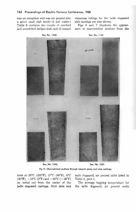
9 UmS S Fig 5 illustrates the appearance of the U 2 5 5 macrostructure present in vacuum spray 2 cast slab No. 1328. This casting was E! i i % $ 5 .,=* a%' -
tapped a t the highest temperature of the
3 , series l76O0C (3200°F), was deoxidized - a m with aluminum and solidified with an air
3> P i ; cast rnacmstructure. Section Nos. 1152, i d 2dg 1345, and 1353 are shown.
s ;= i38 The chemical composition, gas content, = 2s U z N L . : : degassing pressure, and duration of de- gassing treatment for 15 ladle degassed

162 Proceedings of Electric Furnace Conference, 1960
slab castings and for five pairs of ladle Results from four ladle to ladle, spray degassed step-blocks, before and after degassed, ladle degassed, air poured melts, degassing, are shown in Table 5, parts 1 poured at 1500°C (2732°F) are given in and 2, respectively. 3Irlt No. 1515, Table Table 5, part 4.
Sec. No. 1 144 - - - - - - - ,-< r;.;S
Sec ---- No. 1201 - T- - % -7
Sec. No. 1321 Sec No. I I 8 J
Fig 4-Macroetched sections thrwgh vacuum spray cast slab castings.
5, part 3, was ladle degassed and air Table 6 is comparable with Tables 2 poured into standard I-in. keel block legs. and 4 and lists the tensile results and These standard I-in. keel block legs were incidence of fisheye fractures in columns not affected by residual hydrogen or by I, J, K, L, for the ladle degassed, air porosity as test variables. poured, dry sand castings. (Melt 1484

T I B E 4
Vacuwo-Spray-Dep,assed Ideta1 Poured i n t a Cr? Slnd noulds under Vscum
F i l l e d sqvares indicale Lhe presanca uC f isheyes on tens i le bar fractireo, col?lmns E, F, C, H. ( A ) - Alm,it)wn (n) - WGi Cleanncs- RaLiw:- (1) emellent ( 2 ) Good (3) h;r ( 4 ) DirLy.
164 Proceedings of Electric Furnace Conference, 1960
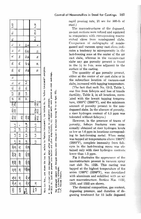
was an exception and was air poured into cleanness ratings for the ladle degassed a green sand slab mold-3 pct water.) slab castings are also shown. Table 6 contains the results of notched Figs 6 and 7 illustrate the appear- and unnotched fatigue tests and of impact ance of macroetched sections from the
See No. 1328 Sec. No. 1 152
Sec. No. 1345 Sec. No. 1353
Fig %Macroetched sections through vacuum spray cost slab castings.
tests a t 93°C (200°F), 27OC (80°F), 4°C ladle degassed, air poured slabs listed in (40°F)) - 18°C (0°F) and -40°C (-40°F) Table 6, part 1. on metal cut from the center of the The average tapping temperature for ladle degassed castings. Melt data and the ladle degassed, air poured melt+
Control o f Nonrnetallics in Steel for Castings 165
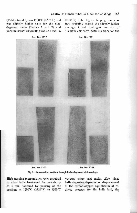
(Tables 5 and 6) was 1700°C (3092'F) and (2822°F). The higher tapping tempera- was slightly higher than for the non- ture probably caused the slightly higher degassed melts (Tables 1 and 2) and average initial hydrogen content of vacuum spray cast melts (Tables 3 and 4). 4.5 ppm compared with 3.5 ppm for the
S e c No. I099 TUy.XL
Sec. No. 1271 1
ww. ,.. _
S e c No. 1275 .- -
Sec. No. 1288
Fig &Macroetched sections through ladle degassed slab castings.
High tapping temperatures were required vacuum spray cast melts. Also, since to allow ladle treatment for periods up ladle degassing depended on displacement to 4 min. followed by pouring of the of the carbon-oxygen equilibrium a t re- castings a t 1500°C (2732°F) to 1550°C duced pressure for the ladle boil, the

Table 5-Chemical and Gas Composition, Casting Pressures, Degassing and Handling Times Part I. Vacuum h d l e Degassed, Air Poured Into Dry 4 n d 81sb Molds
Melt No.
Chemical &mposition (Per Cent)
10. 9.5 6.5 4. 2 .6 2.4 2. 6. 2:OO 4:46 7:lO " 10. 10. 6 .5 4. 2 .6 2.2 1.8- 1:48 3x70 8:OO " 10. 10. 9. 6 . 5 3 . 6 2 . 6 2 . 2 ' 1 0 . 1:35 3:46 6:45
Averago .26 1 . 6 4 .0 4.5 1.4 ,0040 ,0023 ,0033
Hydmen Cootent ( a d
V W U U ~ rn rime a* MIO -in. h i m e n . (mm ~ g i
30 1 90 2 150 3
NI
,014 ,008- ,009 ,002 ,002
,006
,004
,004
,005
,005
,002 ,006- ,004 ,004- .00:1 ,006-
' Time. Time.
zy 1 z:zF 1 2 ~ . Vacuum Hydmg
Ni*" and Owgen Contents'
Ladle
2.9
3.8
4.2
4.1
5.3
3.5
6.6
3.1
4.0
9.0
Tap
3 .1
3.5
4.3
6.0
3.2
5 . 1
2 .2
4.4
3 .3
7 . 0 ,
C hln Si 8 P Cr Boil
" "
a,
"
,,
"
#,
"
,,
"
Min and Sec K
Ns
.003- ,001 ,005 .003 .OM- ,004
,004- .004 ,005- ,002 ,005- ,001
,004- ,001 ,003- .001
Riser
1.9
1. I
1.1
1.6
1.7
2.6
1 .5
0.7
"
I099 I271
I275
1288
1296
1301
I303
1305
1307
1311
1315
8.
7.6
8.
8.
8.
6.
8.
9 . 9 9 .
15.
1:08
4:00
3:30
2:30
2:15
2:OO
2:OO
2:OO
2:15
2:00
01
,003- -003 ,010- ,003 .W6- .003
,013- .006 ,007 ,002 ,008- ,004
,010- ,003 .004- .002
V.F. ---
aec min
.42 -3% .35 .3C- .25
.26
.25-
.23
.24
.XI-
.29
.23-
.23
.29-
.28
.25-
.21
. 2 6
.26
sec
1:26
6:45
7:00
4:26
4:48
5:lO
4:46
4:35
4 5
4:38
5:19
V.F.
7.9
8.5
7.
7 .3
8 . 5 7 . 6 0 .
14.
9:37
9:30
10:50
7:15
6:58
6:50
6:45
6:55
7:lO
6:48
E l 0
.83
.75-
.72
.56-
.53
.76
.&
.57
.76
.84-
.6.5
.66-
.61
.66-
.61
.45-
.39
.71-
.66
min
7.
7.2
7.6
4.5
7.
7 . 6 6 . 8
16.
U).
6.5 9.
7.
2 .7
8 .
6.2
8.
19.
20.
1.8
_ _ - _ C _
2.2
1.6
.6O
.MI-
.a3
. I 6
.1Q
.51
.33-
.35
.61
.44-
.47
.35-
.35
.43-
.43
.12-
.15
.19-
.21
6.8
5.8
2.5
8 .
5 . 8
17.
21.
see min
1.61.4
10.210.5
6.
1.9
7 .5
3.
3 8 3 . 0 2 . 8 5 .
16.
19.
,016 ,016- ,021 ,027- ,026
.O20
.019-
.019
.017 ,024- ,027 ,024- ,027 ,032- ,032 ,027- ,027 ,019- .022
8.58.
7 .5
6.
2.2
10.
20.
1.6' 6.
3.4
8.
6.8
2 . 5
11.
20.
5.
1.9
8.
.018 ,025- ,019 ,032- ,035
,018 ,033- .033
,041 ,038- ,043 ,029- ,031 ,034- ,034 ,043- ,046 ,033-
.22-
.17
.23-
.28
.26
.24
.22
.28
.23
.28
. 2 6
.26
2.6
2.9
1 .1
1.8
2 .8
0 .6
1.4
1.2
2.0
1 . 1
3.0 ,037 .20
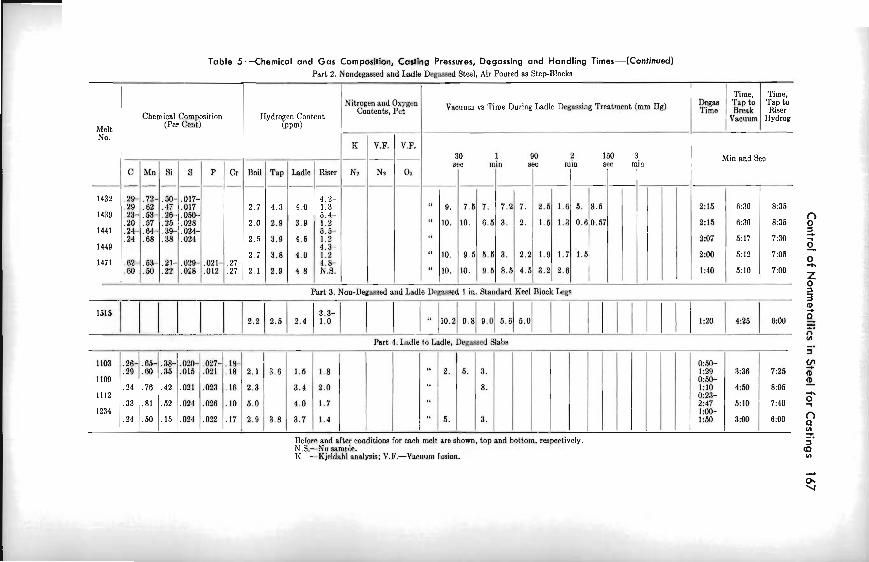
Table 5--Chemical and Gas Composition, Casting Pressures, Degassing and Handling Times-(Continued) Part 2. Nondcamed and Ladle D e m d Steel, Air Poured as StepBloeks
I Chemical Cornpasition
Melt 1 (Per Cent)
No.
Part 3. Non-Deamed and Ladle DQW& I in. Btandard Keel Block Zegs
Part 4. h d l e to Iwdle, Degmed Blabs
I
--- 30 1 90 2 150 3 src min sec min aec min
C Mn fli B P Cr Boil Tap Ladle Riser Nr Na On
1432 .29- .72- .5W .017- 4.2- .29 .62 .47 ,017 2.7 4.a 4.0 1.3 9. 7.5 7. "
1439 .23- .53- . 2 6 ,050- 5.4- .20 .57 .25 ,028 2.0 2.9 3.9 1.2
1441 .24- .64- .39- ,024- 6.5-
Before and after conditions for each melt are shorn, top and bottom, respectively. N.8.-No sample. K -Kj~ldnhl analysis; V.F.-Vacuum lmion.
O m e n
R I V.F. I V.F. Min and Sea
1440
1471
vacuum vs Time During I r d l e Degwina TreatmcnL (mm Ha)
8:3s
8:35
7:30
7 3 5
7:OO
2:15
2:16
2:07
2NJ
1:40
.24
.62-
.MI
6:30
6:.10
5:17
0012
5:lO
.68
.53-
.50
.38
.21-
.22
.024
,029- ,028
-.
,021- ,012
.27-
. 2
2.5
2.7
2 .1
3.9
3.8
2.9
4.5
4.0
4 .8
1.2 4.3- 1.2 1.8- N.S.
"
" 10.
10.
9 .5
10.
6.5
4.5
3.
8.5
2.2
4.5
1.9
3.2
1.7
2.0
1.6
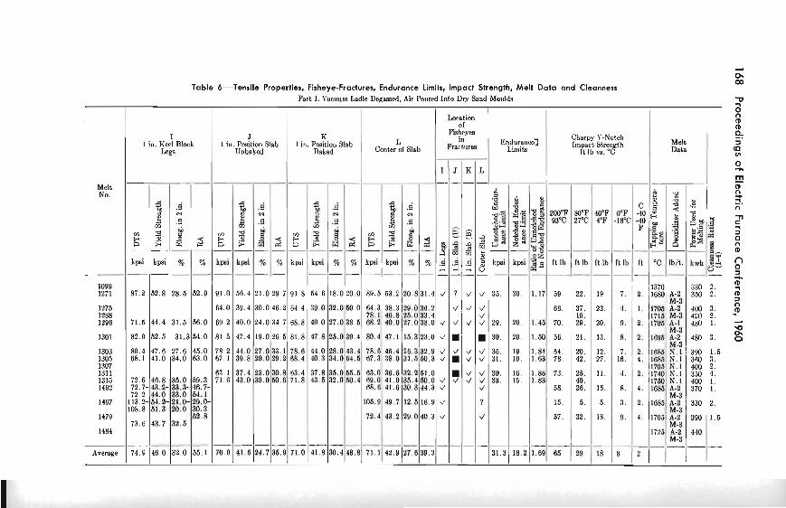
Table 6-Tensile Properties, Fisheye-Fractures, Endurance Limits, Impact Shength, Melt Data and Cleanness Part I. Vncuurn Ladle Degmed, Air Poured Into Dry Sand Moulds
Charpy V-Notch 1 in. Keel Block I in. Pceition Slab I in. Position Slab IrnpacL Slrength Melt
Leg8 Unbaked It Ib vs. "C D a b
I J K L
Melt No. 2 2
= d c g 3 2 200°F 80°F 40°F O°F -40 93'C 2 7 T 4.F -IF? -40 5 3 - 2
F .s 'a ,'.. .G
E$ g $ 5 2 - - - - - - - - - - - - - - - - F- a g - - -- -- - - -- -
a? ft lb I i lb It lb It lb It "C Ib/t. k w h j&
0 ------- ---------- I099 1370 330 2 . 1271 8 7 . 2 5 2 . 8 2 8 . 5 5 2 . 9 9 1 . 0 5 6 . 4 2 1 . 0 2 9 . 7 9 1 . 8 5 4 . 6 1 8 . 0 2 0 . 0 ' 8 9 . 5 5 3 . 2 2 0 . 8 3 1 . 4 4 ? 4 4 35. 30. 1.17 59. 22. 19. 7. 2 . 1680A-2 350 2.
M-3 1275 66. 37, 22. 4. I . 1705 A-2 400 3. 1288 19. 1715 M-3 450 2. 1296 7 1 . 6 4 4 . 4 3 1 . 5 5 8 . 0 70. 29. 2 0 . 9 . 2 . 1705A-I 480 1.
M-3 1301 82.9 52.5 31.364.0 56. 21. 13. 8 . 2. 1695 A-2 480 3.
M-3 1303 80.4 47.6 U . 6 45.0 64. 20. 1 2 , 7. 2. 1 0 8 5 S . 1 390 1.5 1306 6 8 . 1 4 1 . 0 3 4 . 0 63.0 78. 42. 27. 16. 4. 1 6 8 5 N . I 360 3. 1307 I705 N.l 400 2. 1311 73. 25. 11. 4. 2. 1740N.1 350 4. 1315 72.6 46.8 :35.0 60.3 40. I750 N. l 400 1. 1462 72.7- 43.2- 33.3- 46.7- 68.6 41.6 30.3 44.3 v' d 58. 26. 16. 8 . 4. 1685 A-2 370 I.
72 2 44.0 33.0 64.1 M-3 1407 113.2-54.2- 21.0-29.0- 105.9 49.7 12.5 16.9 4 ? I 5 5. 3 . 2. 1685 A-2 330 2.
108.8 51.3 20.0 30.3 M-3 1479 62.8 72.4 43.2 29.0 40.3 4 4 57. 32. 18. 9. 4. 1705 A-2 390 1.6
73.6 43.7 32.5 M-3 1484 1725 A-2 440
M-3
Average 74.9 46.0 32.0 55.1 70.9 31.3 18.2 1.89 65
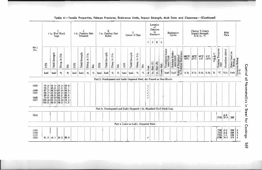
Table 6-Tensile Properties, Fisheye Fractures, Endurance Limits, Impact Strength, Melt Data und Cleanness-(Continusdj
I1 h a t i o n of
I J I< Fisheye
in FmrLum Enduranm
Charpy V-Notch l in. Kwl Block l i n Paition Blab I I in. Paition Slab Impact Stwn~th Melt
Lee Unbaked Baked Center or Slab Liu~i(a It 1b vs. "C Data
I Melt - -
No.
-- Part 2. NondesRssed and Ladle Degwed Ster!, Air Poured as StrpBloeka -- -- -.
d I ./ d "' d 4
--- I I Part 3. Nondemed and Ladlc D m 1 in. Standard Kml Blook Leas
ParP 4. Iadlc to ladle, Dwsssed Slabs

170 Proceedings of Electric Furnace Conference, 1960
average carbon content of this series of were tapped and poured a t the same melts was slightly lower, 0.26 pct carbon, temperature as melt No. 1286, Table 1. than the average 0.30 pct carbon contents Slabs Nos. 1286 and 1288 were poured a t
Sec No. 1296 Sec No. 1303 .---=. - ~. - - - .- - .- - I . . . . ... . : , , ,., . - . ~~ . -- . .
. i . . , . . - . .
_g:,,.;: . . *? .i,\ .- .- .
, , ..: ?<, .: :&:. ,. I : _ _.. _ I. . . * ' . ' ..< *:,;,,,:.. .' . . 'id'& ;-' .' : ..:Goo?f, :[' . . . '.:<.<. ,$: .& .. :$%& .*!? F,j.*-, :..:.a .: . .. . ~ .. -
,,;$ :3:;. ;?. :
".,. - : ! . , .
, .
. : $14 .;,. :, .
: .. .:*>. .
Sec. No. 1305 Sec. No. 1 3 1 5
Fig 7-Macroetched sections through ladle degassed slab castings.
of the nondegassed and spray degassed 1525°C (2777OP) into dry sand molds melts. after tapping a t 1715OC (311g°F), with
To test the importance of pouring tern- riser hydrogen contents of 6.3 and 1.6 perature as a variable, several ladle ppm, respectively. Melt No. 1286 was degassed melts (e.g., No. 1288, Table 5) described previously and contained fisheye
Control of Nonmetallics in Steel for Castings 171
fractures in tensile bars after storage for Table 7 lists the chemical composition, 1% years whereas the tensile bars cut gas content, casting pressures and melt from the center of slab No. 1288, having data for two heats which were dead
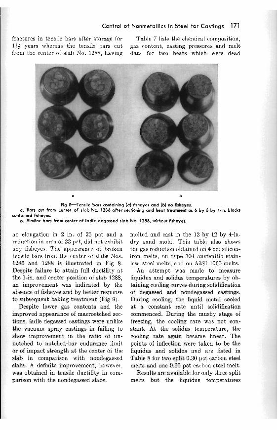
Fig 8-Tensile bars containing (a) fisheyes m d (b] MI flsheyes. a. Bars cut from center of slab No. 1286 after sectioning and heat treatment as 6 by 6 by 4-in. blocks
contained fisheyes. b. Similar bars from center of ladle degassed slab No. 1288, without fisheyes.
an elongation in 2 in. of 25 pct and a reduction in area of 33 pct, did not evhibit any fishcch. The appearance of broken tensile bars from the ceuter of slabs Nos. 1286 and 1288 is illustrated in Fig 8. Despite failure to attain full ductility a t the 1-in. and center position of slab 1288, an improvement was indicated by the absence of fisheyes and by better response to subsequent baking treatment (Fig 9).
Despite lower gas contents and the improved appearance of macroetched sec- tions, ladle degassed castings were unlike the vacuum spray castings in failing to show improvement in the ratio of un- notched to notched-bar endurance limit or of impact strength a t the center of the slab in comparison with nondegassed slabs. A definite improvement, however, was obtained in tensile ductility in com- parison with the nondegassed slabs.
melted and cast in the 12 by 12 by 4-in. dry sand mold. This tahlc also shows the gas reduction obtained on 4 pct silicon- iron melts, on type 301 austenitic stain- less steel melts, and on AISI 1060 melts.
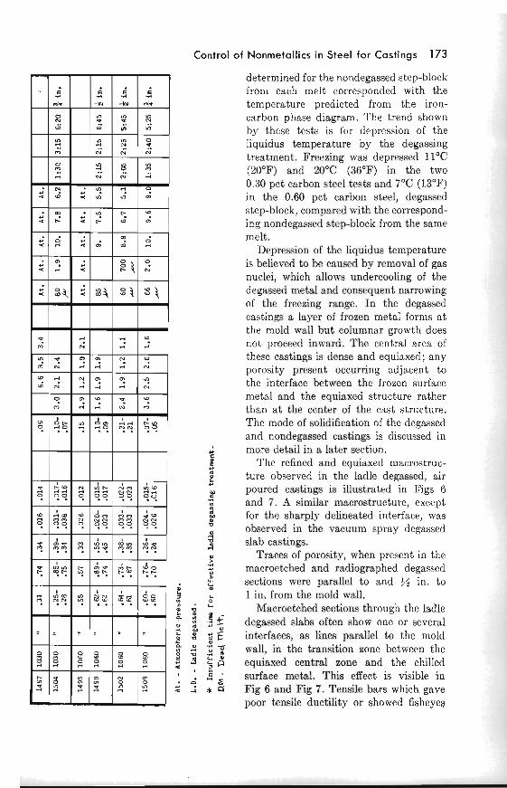
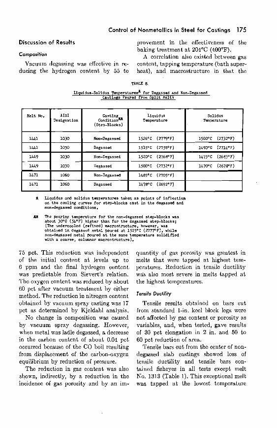
An attempt was made to measure liquidus and solidus temperatures by ob- taining cooling curves during solidification of degassed and nondegassed castings. During cooling, the liquid metal cooled a t a constant rate until solidification commenced. During the mushy stage of freezing, the cooling rate was not con- stant. At the solidus temperature, the cooling rate again became linear. The points of inflection were taken to be the liquidus and solidus and are listed in Table 8 for two split 0.30 pct carbon steel melts and one 0.60 pct carbon steel melt.
Results are available for only three split melts but the liquidus temperatures
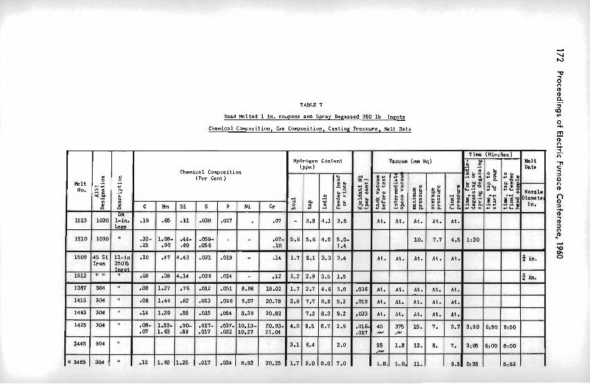
TABLE 7
Dead Melted 1 in. coupons and Spray Degassed 350 lb Ingots
.Chemical Composition, Gas Composition, Casting Pressure. Melt Data
- Time (Min:Sec) Hydrogen Content Vacuum (mm Hq) u c I M nelt
( P P ~ ) A ,A Data Chemical Composition - - - - - " 8 (Per Cent )
Melt ,; C P No. .c:! ...
*.Y !i
c Mn S ~ I S P ~i Cr
1513 1 W 0 1-in. .19 At. At. At. At. At. Legs - - ----
1510 1030 " .32- 1.08- .44- .059- - .07- 5.6 5.6 4.9 5.0- 10. 7.7 4.5 1:20 .25 .90 .40 .056 .10 1.4
1509 4% Si 11-in .10 .47 4.42 .021 .019 - .14 1.7 2.1 3.3 3.4 At. At. At. At. At. 3. in. Iron 3501b
lneot -. -- 1512 tm B* M .08 .38 4.14 .026 .014 - .12 3.2 2.9 3.5 1.5 * in.
r - 1387 304 -08 1.27 .76 .012 .051 .02 1.7 2.7 4.61 5.8 .038 At. At. At. At. At. "
1415 , 304 " -08 1.44 .82 .OD .026 ,78 2.9 1.7 8.9 9.2 .019 At. At. At. At. At. 1.
1463 304 .14 1.29 .85 .015 ,054 U.JY ~u.82 1.2 8.3 9.2 ,033 At. At. At. At. At. "
1425 304 -08- 1.53- .90- ,017- ,037- 10.13- 20.93- 4.0 8.5 8.7 3.9 ,016 45 375 15. I. 3.7 3:50 6:50 9150 " '
.07 1.63 .89 ,017 ,032 10.27 21.04 I ,017 . - , lu -
1445 304 3.1 6.4 55 " 1.8 13. 8. I. 3:05 6:OO 8:OO
- - &+ --- --- ------------ 91485 304. -12 1.60 1.25 ,017 .M4 8.92 20.25 1.7 9.0 8.0 7.0 "
L.D. L.D. 11. 9.5 0:35 5:s
Control of Nonmetallics in Steel for Castings 173
determined for the nondegassed step-block from each melt corresponded with the temperature predicted from the iron- carbon phase diagram. The trend shown by these tests is for depression of the liquidus temperature by the degassing treatment. Freezing was depressed 11°C (20°F) and 20°C (36°F) in the two 0.30 pct carbon steel tests and 7 O C (13°F) in the 0.60 pct carbon steel, degassed stcp-block, compared with the correspond- ing nondegassed step-block from the same melt.
Depression of the liquidus temperature is believed to be caused by removal of gas nuclei, which allows undercooling of the degassed metal and consequent narrowing of the freezing range. In the degassed castings a layer of frozen metal forms a t the mold wall but columnar growth does not proceed inward. The central area of these castings is dense and equiaxed; any porosity prcscnt occurring adjacent to the interface bctween the frozen surface metal and the equiaxed structure rather than a t the center of the cast structure. The mode of solidification of the degassed - and nondega,ssed castings is discussed in
C more detail in a later section. i The refined and equisxed macrostruc-
ture observed in the ladle degassed, air C
t poured castings is illustrated in Figs 6 and 7. A similar macrostructure, except for the sharply delineated interface, was
w observed in the vacuum spray degassed 3
slab castings. a Traces of porosity, when present in the 5 macroetched and radiographed degassed
sections were parallel to and 54 in. to
; 1 in, from the moId wall. m . L a .3 L a Macroetched sections through the ladle " 2 8 f degassed slabs often show one or several 2 & '. l S Z E interfaces, as lines parallel to the mold
: urall, in the transition zone between the 9 6 equiaxed central zone and the chilled < l v )
a surface metal. This effect is visible in . d " E Z i 4 a Fig 6 and Fig 7. Tensile bars which gave
poor tensile ductility or showed fisheyea
174 Proceedings o f Electric Furnace Conference, 1960
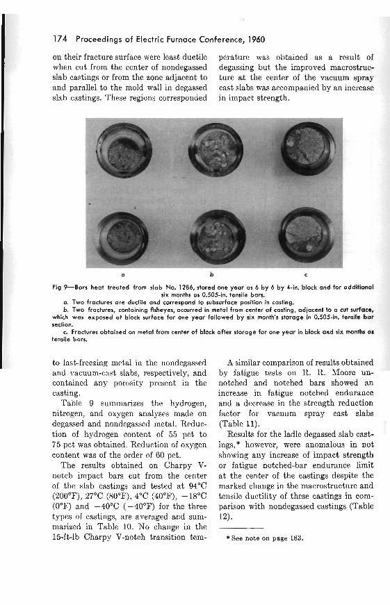
on their fracture surfa.ce were least ductile perature was obtained as a result of when cut from the center of nondegassed degassing but the improved macrostruc- slab castings or from the zone adjacent to ture a t the center of the vacuum spray and parallel to t,he mold wall in degassed cast slabs was accompanied by an increase slab castings. These regions corresponded in impact strength.
Fig 9-Ban heat treated from slab No. 1286, stored one year as 6 by 6 by 4-in. block and for additional six months as 0.505-in. tensile bars.
a. Two fractures are ductile and correspond to subsurface position in casting. b. Two fractures, containing fisheyes, occurred in metal from center of casting, adjacent to a cut surface,
which was exposed at block surface for one year followed by six month's storage in 0.505-in. tensile bar section.
c. Fractures obtained on metal from center of block after storage for one year in block and six months as tensile bars
to last-freezing metal in the nondegassed and vacuum-cast slabs, respectively, and contained any porosity present in the casting.
Table 9 summarizes the hydrogen, nitrogen, and oxygen analyses made on degassed and nondegassed metal. Reduc- tion of hydrogen content of 55 pct to 75 pct was obtained. Reduction of oxygen content was of the order of 60 pct.
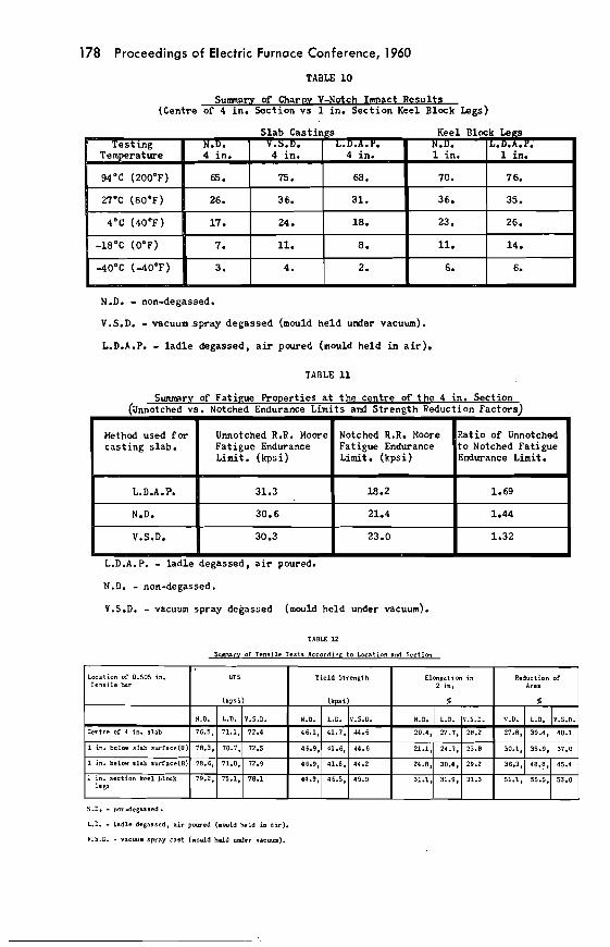
The results obtained on Charpy V- notch impact bars cut from the center of the slab castings and tested a t 94OC (200°F), 27OC (80°F), 4°C (40°F), -18OC (0°F) and -40°C (-40°F) for the three types of castings, are averaged and sum- marized in Table 10. No change in the lbft-lb Charpy V-notch transition tem-
A similar comparison of results obtained by fatigue tests on R. R. Moore un- notched and notched bars showed an increase in fatigue notched endurance and a decrease in the strength reduction factor for vacuum spray cast slabs (Table 11).
Results for the ladle degassed slab cast- ings,* however, were anomalous in not showing any increase of impact strength or fatigue notched-bar endurance limit a t the center of the castings despite the marked change in the macrostructure and tensile ductility of these castings in com- parison with nondegassed castings (Table 12).
* See note on page 183.
Control of Nonmetallics in Steel for Castings 175
Discussion of Results provement in the effectiveness of the baking treatment a t 204OC (400°F).
Composition A correlation also existed between gas Vacuum degassing was effective in re- content, tapping temperature (bath super-
ducing the hydrogen content by 55 to heat), and macrostructure in that the
TABLE 8
Uquidue-Solidus ~enperatures* for Degassed and Non-Degassed Castings Poured from Spl i t Uelts
Liquidus and solidus temperatures taken a s points of inflection on the cooling curves for step-blocks cast i n the degassed and non-degassed conditions.
U The pouring temperature for the non-degassed step-blocks was about 30°C (~LOF) higher than for the degassed step-blocks; (The undercooled (refined) macrostructure, however, was obtained i n degassed metal poured a t 1525OC (2777°P), whila non-degassed metal poured a t the same temperature s o l i d i f i e d with a coarse, columnar macrostructure).
75 pct. This reduction was independent quantity of gas porosity was greatest in of the initial content a t levels up to melts that were tapped a t highest tem- 6 ppm and the final hydrogen content peratures. Reduction in tensile ductility was predictable from Sievert's relation. wis also most severe in melts tapped a t The oxygen content was reduced by about the highest temperatures. 60 pct after vacuum treatment by either method. The reduction in nitrogen content - obtained by vacuum spray casting was 17 Tensile results obtained on bars cut pct as determined by Kjeldahl analysis. from standard 1-in. keel block legs were
No change in composition was caused not affected by gas content or porosity as by vacuum spray degassing. However, variables, and, when tested, gave results when metal was ladle degassed, a decrease of 30 pct elongation in 2 in. and 50 to in the carbon content of about 0.04 pct 60 pct reduction of area. occurred because of the CO boil resulting Tensile bars cut from the center of non- from displacement of the carbon-oxygen degassed slab castings showed loss of equilibrium by reduction of pressure. tensile ductility and tensile bars con-
The reduction in gas content was also tained fisheyes in all tests except melt shown, indirectly, by a reduction in the No.1313 (Table 1). This exceptional melt incidence of gas porosity and by an im- was tapped a t the lowest temperature
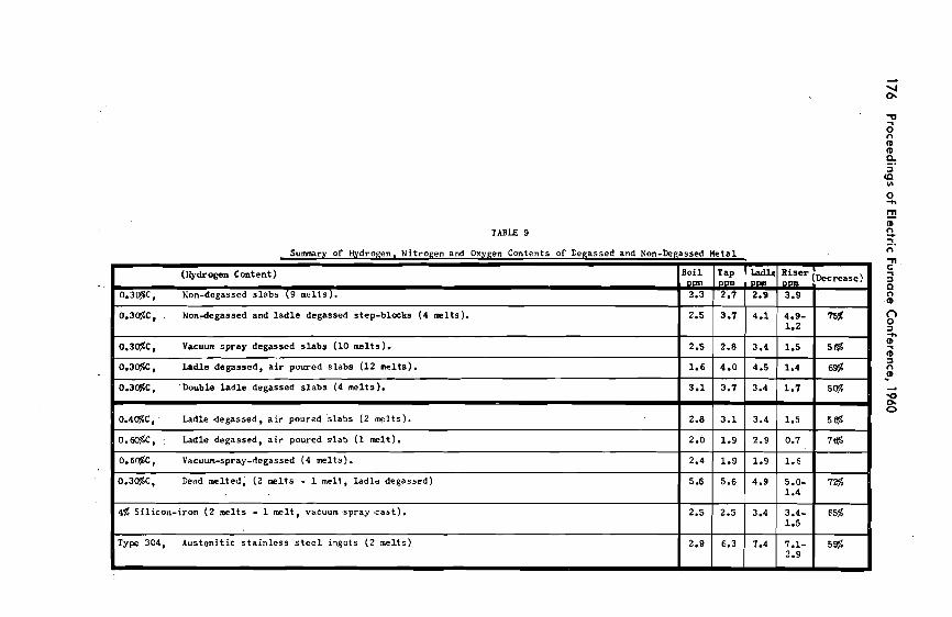
TABLE 9
0.307.C. . Nondegassed and l a d l e degassed step-blocks (4 melts). I 2.5 1 3.7 1 4 1 1 - 1 I*
Summary of Hydrogen, Nitrogen and Oxygen Contents of Degassed and Non-Degassed Metal
I I I I I
0.3@C, Vacuum spray degassed s l a b s (10 melts). 1 2.5 1 2.8 1 3.4 1 1.5 ( 513%
(wdrogen Content) Boil Don
0.4@C, Ladle degassed, a i r poured s l a b s ( 2 melts) . I 2.8 1 3.1 1 3.4 1 1.5 1 5 %
0.3C$C, Non-degassed s l abs (9 melts 1. 1 2.3 1 2.7 1 2.9 1 3.9 1
Tap 1 b d l e D m l D P m
0.3@C, Ladle degassed, a i r poured s l abs (12 melts).
0.3@C, 'Double l a d l e degassed s l a b s (4 melts).
R i se r lDecrease) DW r
0.3051.C. Dead melted, ( 2 melts - 1 melt, l a d l e degassed) I 5.6 1 5.6 1 4.9 I :f 1 7%
1.6
3.1
0.@C, - Ladle degassed, a i r poured s l a b ( 1 melt) .
0.6@C, Vacuum-spray-degassed (4 melts).
4% Si l icon- i ron ( 2 melts - 1 melt, vacuum sp ray .cast). 1 2.5 1 2.5 1 3.4 1 3 4 1 65% 1 5
4.0
3.7
2.0
2.4
Type 304, Austeni t ic s t a i n l e s s s t e e l ingots (2 melts)
4.5
3.4
1.9
1.9
2.9
1.4
1.7
2.9
1.9
6 s
5%
6.3
0.7
1.6
7@
7.4 7.1- 2.9
m a
a r( n I
4
F m
i a 1 F P
4 a CI
s 2 .., d a : ; a a n -4 I. 4 a - 2 + '2 ~ U Q 4 1 - 2 2 , " m u -
3 , $0 ~ 2 % * I . : w 0 . u
a n PI
w . - - C C C
E g E . . . C C C
C + ' + c c c
E E 6 - 0 0 0 2 2 2 c 8 s 8 C C C C - u u u PI PI C c u z c c c
0
O$l.$ t t t U 4 0 p g g C G C G U
u o" t t t g t t t ~ a a a t E 2 w e < < -
g g g " 2 ' i$% g d o 2 % 2
Control of Nonmetallics in Steel for Castings 177
of the air cast series of slab castings, 1585OC (2885OF) and was silicon-killed.
Tensile bars cut 1 in. beneath the sur- face of nondegassed castings always showed some loss of tensile ductility and frequently showed fishcyes on tensile bar fractures when the metal for casting was - tapped a t tcmperatures higher than 1585OC (2885OF). Several melts tapped a t 1600°C (2912°F) contained less than 2.5 ppm hydrogen throughout melting and in the riser. Thcse mclts showed less reduction in tensile ductility than similar nondegassed melts tapped a t higher tem- peratures or a t higher hydrogen contents. Some improvement with respect to fish- eyes and tensile ductility was obtained in the low-hydrogen nondcgassed melts but the castings mere definitely inferior to melt No. 1313.
It was established from examination of the results for nondegassed stcel (Table 2) that the incidence of fisheyes correlated with furnace superheat. These defects were most severe in the central area of castings poured with metal tapped a t a high temperature. This was especially truc when the high tapping temperature coincidcd with a high riser hydrogcn
C . content. No direct correlation of the inci-
1 dence of fisheyes with pouring tem- 4- . + a , perature was observcd in the tempera-
0) a 2 ture range 1525°C (2777OF) to 160Q°C C
d C PI a
C
: : e b t (2912°F). The correlation with tapping k t temperature indicated that porosity was
; , , a lr , , , one prereq~~isi te for fisheye fracture. Baking PI L '4 .., P a m of tensile bars cut from the center of the - - 4
.1 .: I I air cast slabs resulted in partial restora- a a
5 2 g c tion of tensilc ductility but did not always
$ ,. .= .: a 9 eliminate the appearance of fisheyes on
d d lr lr r r a a E E bar fractures aftcr 70 hr a t 204OC (400°F). Z1 4 2 1 However, when affected bars were normal-
u u S S g d ized (austenitized) and tempered in the
I I 0.505-in. sections, the tensile elongation I I I I I I . . in 2 in. was restored to about 28 pct
a 4 and the reduction of area to about 48 pct. ' ? ? L - ' - x se * * The diffcrence between these figures and
the comparable figures, 30 pct and 53 pct,
178 Proceedings of Electric Furnace Conference, 1960
TABLE 1 0
Surnnary of Charpr V-Notch Imuact Resu l t s (Centre of 4 in. Section vs 1 in. Sect ion Keel Block Legs)
N.D. - non-degassed.
V.S.D. - mcuum .spray degassed (mould held u d e r vacuum).
L.D.A.P. - l a d l e degassed, a i r poured (mould held i n a i r ) .
TABLE 11
Summar of F a t i e R e r t i e s a t t h e centre of t h e 4 in. Section (Unnotched :s . Notch2 End2ance Limits and Strength Reduction Factors)
L.D.A. P. - l ad le degassed, a i r poured.
N.D. - non-degassed.
V.S.D. - vacuum spray degassed (mould held under vacuum).
TABLE 12
SWTY OC Tensi le Tertr Accordine t o Location a d S e c t i m
1 h a t i o n r 0.505 in. T e n s i l e tur
I Yield Strength I Flp-
N.D. - nondegasred.
L.D. - l a d l e degassed, air p-ed (narld held in a i r ) .
V.5.D. - vncmm spray cast (mould held under vacuun).
Control oi F Nonrnetallics in Steel for Castings 179
respectively, for the standard 1-in. section keel block legs, was attributed to the presence of microporosity without hy- drogen. This indicated that fisheyes formed only when the pores contained hydrogen and that the presence of hydrogen was a second prerequisite condition re- quired for the formation offisheyes.
I t was observed that in air cast melt No. 1313, which had received the mini- mum amount of furnace superheat, 1585°C (2885°F) and was subsequently silicon-killed and air poured a t 1525°C (2777"F), full ductility was obtained throughout the slab casting despite a riser hydrogen content of 4.5 ppm. Exami- nation of the macroetched section revealed no obvious difference in macrostructure, as compared with other air cast sections, except for a reduction in porosity in the central area.
The other air cast slabs which were tapped a t 1625°C (2957°F) resembled the low-hydrogen melts in their tendency to show fewer fisheyes and to have greater tensile ductility than similar castings pre- pared with hotter metal.
Attempts to pour ductile 4-in. section slab castings using nondegassed metal for this particular test casting were not successful, except for melt No. 1313, where the pouring conditions were ideal.
Similar slab castings poured with vacuum spray degassed metal or with ladle degassed metal did not contain fish- eyes in tensile bar fractures unless . the hydrogen content was above 1.5 ppm. Full tensile ductility was usually obtained in bars cut from the center of the casting. Some loss of tensile ductility and occa- sional fisheyes were obtained in degassed melts, if the riser hydrogen content was greater than 1.5 ppm, on bars taken 1 in. from the casting surface. Even when loss of tensile ductility or fisheyes was likely to be present, at riser hydrogen contents above 1.5 ppm, these conditions were easily avoided or eliminated by the low-
temperature 70-hr 204°C (400°F) baking treatment. Unlike the nondegassed tensile bars, none of the tensile bars obtained from vacuum-cast metal required the normalizing and tempering treatment, in the 0.505-in. bar section, to obtain full ductility.
The change in tensile ductility co- incided with changes in the macrostruc- ture of vacuum-cast slabs, which reduced the porosity of the central area and trans- ferred the last-freezing zone and any ac- companying porosity to a subsurface zone.
Macrostructure
A comparison of etched sections from air cast, vacuum spray cast and ladle degassed air poured slabs was made for 0.30 pct carbon steel melts having riser hydrogen contents of 0.5 to 6 pprn and furnace tapping (superheat) tempcra- tures of 1585°C (2885°F) to 1760°C (3200°F). Each group of tests contained castings poured with silicon-killed metal, or fully killed with aluminum and cal- cium-manganese-silicon.
The only variables that correlated with casting macrostructure mere the degassing method, gas content, and the amount of superheat of the furnace bath as shown by the ta.pping temperature.
All sections through nondegassed, air cast slabs had typical columnar crystal structures, with dendrites extending in- ward from the surface of the casting and leaving narrow equiaxed crystal zones. The central, equiaxed zone appeared to contain last-freezing metal and tended - to be porous even when exothermic riser inserts and metal with a hydrogen con- tent of 2 pprn were used.
All sections through vacuum spray cast slabs, prepared with dry sand molds in- side the evacuated tank, showed a change in macrostructure, so that the cast section consisted mainly of small equiaxed crys- tals except for a shallow surface region where growth of columnar crystals may
180 Proceedings of Electric Furnace Conference, 1960
have started. The zone of last-frozen metal was not a t the center of the casting but was present in a position parallel to the mold wall and about )S in. to 1 in. beneath the surface of the casting. Con- siderably less porosity was present than in the nondegassed castings and, when traces were present, the location of the porosity coincided with the subsurface zone of last-frozen metal. One of the advantages of vacuum spray casting over ladle degassing mas the opportunity to degas both the metal and sand mold prior to casting. During casting, the mold was held under vacuum. 'These castings were considerably improved over the air cast slabs with respect to tensile ductility, absence of fisheyes, Charpy V-notch impact strength and notched-bar endur- ance limit. (Only one exceptional melt, heated to 1760°C (3200°F) and aluminum- killed while hot, failed to show the refined macrostructure typical of the vacuum- cast slabs. This heat No. 1328, Table 3, developed a macrostructure similar to that of the nondegassed castings despite vacuum spray casting. Failure of this melt to cool below the normal liquidus temperature probably resulted from ex- cessive solution of oxygen in the bath a t the high temperature. When the alumi- num addition was made a t tap, an exces- sive quantity of A1203 was probably formed, which provided sufficient nuclei to offset any reduction in gas nuclei obtained by the degassing treatment.)
Sections through ladle degassed, air poured slabs, cast in dry sand molds, exhibited the equiaxed macrostructure typical of all the degassed castings. An abrupt transition occurred between the equiaxed interior of the casting and the shallow layer of frozen metal and colum- nar crystals in contact with the mold wall. These castings were not poured under vacuum and this may have contributed to the less dense macrostructure as com- pared with the spray cast slabs.
The ladle degassed slabs were inter- mediate in quality between, the nonde- gassed and the vacuum spray cast slabs. The necessity for superheating of the furnace bath to coufiteract loss of tem- perature during the ladle degassing treatment was a disadvantage of this method as applied to small 500-lb melts for steel castings.
The tensile ductility of these castings was im~roved to about the same extent as for vacuum spray cast slabs. When the riser hydrogen content exceeded 1.5 ppm, there was a tendency for loss of tensile ductility and for the occurrence of fisheyes in bars cut a t the 1-in. position of the casting. However, unlike the nondegassed bars, baking for 70 hr a t 204°C (400°F) was effective in diffusing the hydrogen out of porous areas and full ductility throughout the casting was obtained by combining the dehydrogcnizing bake and the ladle degassing treatments.
The difference in macrostructure ob- served for degassed steel castings as com- pared with nondegassed castings appears to be explainable on the basis of under- cooling, spontaneous nucleation, and rapid solidification with the last-freezing, low-melting-point liquid present a t the interface between the chilled zone and the equiaxed crystal zone. Some con- firmation of this hypothesis is demon- strated by the evidence of depression of the liquidus temperature and narrowing of the freezing range of vacuum degassed metal as compared with nondegassed metal from the same melt.
Fatigue Properties
Comparison of the endurance limits on unnotched and notched R. R. Moore fatigue bars, for air cast, vacuum spray cast; and ladle degassed, air poured cast- ings showed that the strength reduction factor a t the center of the vacuum spray cast slabs was reduced relative to the air cast standard but that the ladle de-
Control of Nonmetallics in Steel for Castings 181
gassed slab's strength reduction factor was increased.
Since the gas contents, macrostructures, and degree of porosity of the two vacuum- cast types of slabs were approximately similar, the most significant difference appears to be the fact that the dry sand mold is degassed under vacuum prior to pouring, and is held in vacuum during the pour, whereas pouring of degassed metal under normal atmospheric conditions re- quires the usual precautions to avoid oxidation during the pour and the pres- ence of air in the mold during casting.
Use of a bottom-pour ladle for the vacuum spray cast slabs and of a lip- pour, high-walled treatment ladle for the ladle degassed slabs might favor the spray cast slabs with respect to cleanness. However, no significant difference in cleanness was observed by radiographic examination of %-in. sections, by exami- nation of the macroetched slices or by comparison of the unnotched fatigue en- durance limit on bars cut from the center of the normalized and tempered blocks.
Another variable that is difficult. to control with ladle degassing tests on small melts is the relatively short holding time between the vigorous ladle boil and pour- ing of the casting. Increase of holding time after degassing did not seem to offset the lower than normal fatigue-notched en- durance limits obtained with ladle de- gassed 4 in. castings.
Chorpy V-Notch Impact Results
Degassing did not effect any change in the 15-ft-lb Charpy V-notch transition temperature for either the vacuum spray cast or ladle degassed, air poured castings in comparison with nondegassed stand- ards. However, the combination of lower gas content, improved center macrostruc- ture, and reduced porosity obtained a t the center of vacuum spray poured test castings resulted in an increase in impact strength values a t 4°C (40°P), 27OC
(80aP), and 93OC (200°P). The increase in impact strength a t the center of vacuum spray cast slabs corresponded to the re- duction of porosity and increase of tensile ductility noted in these castings.
liquidus Temperature and Freezing Range
Cooling curves were obtained for de- gassed and nondegassed melts and were compared. The point where the rate of cooling became nonlinear was believed to be the liquidus point. Throughout' the freezing range, the rate of cooling was not constant, until, a t the solidus tempera- ture, the rate of cooling again. became linear. If this method is accurate, the results show a depression of the liquidus temperature and a narrowing of the freez- ing range. In addition to explaining the refinement of as-cast macrostructure, undercooling should result in improved fluidity for metal cast a t temperature near the liquidus temperature. The narrower freezing range should also reduce the time available for " coring" segrega- tion during solidification, and might reduce the extent of gas por'osity or microshrinkage. . .
Casting Preskre;
The casting pressures obtained during this series of tests were 30 to 90 microns before casting when the tank contained an empty ingot mold or dry sand casting. The pressures obtained with the hot metal and furnace ladle sealed on top of the tank and the intermediate space connected to the main tank were 180 microns to 2.2 mm Hg with 6 out of 10 tests having pressures of 700 microns or less a t the start of the pour. During. the pour, the pressures usually rose to a maximum of 12 mm Hg (range 3.5 to 20 mm Hg).
Conclusions
1. Vacuum spray degassing and ladle degassing of 500-lb melts of 0.30 pct

182 Proceedings of Electric Furnace Conference, 1960
carbon steel gave final riser hydrogen contents of 1.0 to 1.5 pprn for a reduction of 50 pct to 75 pct. Reduction of the hydrogen content was independent of the initial hydrogen content, a t least with initial contents up to 6 ppm. Reduction in oxygen content by about 60 pct to an average final content of 33 pprn was obtained by both degassing methods.
2. Full tensile ductility was obtained throughout .the 4-in. section test casting by either degassing method providing the hydrogen content was reduced below 1.5 ppm.
3. Degassed castings had fine-grained, equiaxed macrostructures, which were attributed to undercooling followed by spontaneous nucleation and rapid solidifi- cation as a consequence of a narrowing of the normal freezing range. The zone of last-frozen metal (porous area), normally present a t the center of the casting was displaced to a subsurface location about
in. to 1 in. from the mold wall in de- gassed castings.
4. Ladle degassed castings maintained full tensile ductility throughout the 4-in. section a t hydrogen levels below 1.5 ppm. Even a t hydrogen levels above 1.5 ppm, full tensile ductility was easily restored by a 204°C (400°F) 70-hr bake. No reduc- tion of the 15-ft-lb Charpy V-notch impact-transition temperature or increase of Charpy V-notch impact strength a t ambient temperature was observed after the ladle degassing treatment under the test conditions.
5. Vacuum spray degassed castings, poured with the mold held inside the evacuated tank prior to and through- out the pour, had full tensile ductility throughout the casting provided the hy- drogen content was reduced below 1.5 ppm. The dense equiaxed macrostructure obtained contained less porosity than was present in nondegassed standard castings. The improvement in macro- structure was demonstrated by an in-
crease of Charpy V-notch impact strength and by increased fatigue-notched endur- ance limit.
6. All the nondegassed 12 by 12 by 4-in. standard castings gave reduced tensile ductility a t the center of the 4-in. section (except for one melt). The tensile bars from the center area contained gas poros- ity, which increased with increase of tapping temperature (furnace bath super- heat) or with increase of hydrogen con- tent. Removal of the porosity or reduction of the hydrogen content to less than 1.5 pprn restored the tensile ductility.
7. It was possible to tolerate a riser hydrogen content of 4.5 pprn in the test casting if the section was absolutely sound. This latter condition so restricted the tapping temperature to less than 1585°C (2885°F) that, despite the prepa- ration of melts having hydrogen contents of less than 2 pprn throughout melting, an increase of 15°C (27°F) in tapping temperature caused loss of tensile ductility and fisheye fracture. Attempts to improve feeding by increasing the height of the riser or by use of exothermic sleeve in- serts were not successful. However, with vacuum degassed steel and a hydrogen content of less than 1.5 ppm, tapping and pouring conditions were not critical throughout the normal range of tapping temperatures, 1600°C to 1730°C (2912°F to 3128°F).
8. Full tensile ductility and a complete absence of fisheye fracture was always obtained when metal from the test melts was cast into the standard 1 by 1 by 6-in. keel block legs. This 1-in. section was always free from porosity and did not retain hydrogen.
Acknowledgments
The author acknowledges with thanks the assistance of Messrs. G. Smelsky and J. Garrison of the Physical Metallurgy Division, Mines Branch, Department of

Control of Nonrnetallics in Steel for Castings 183
lMines and Technical Surveys, in making gas analyses and in carrying out the vacuum casting program, respectively.
References
1. Smith, G., D. E. Parsons, and W. A. Morgan: Vacuum-Degassing of Metals- a Survey of Published Work and the Application of Theoretical Principles to the Degassing of Steels. Physical Metal-
Discussion S. 0. Smith presiding
C. B. WILLIAMS-I noticed in the preprint some variations in silicon con- tent from 0.4 to 0.8 pct levels. I wondered why that was. Also that when the tapping, temperature was raised 27 deg F, it seemed to increase the gas content. I wondcr if Dr. Parsons could explain these results.
D. E. PARSONS-Several high-silicon melts are included in Table 1. These resulted, occasionally, when excess FeSi was used to turn the reducing slag. How- ever, neither the tensile ductility nor the incidence of fisheye fracture was signifi- cantly affected by variation of the silicon content, except that the fisheyes may have been slightly larger in the non- degassed melts containing 0.80 pct silicon. This was shown by loss of tensile ductility and the presence of fisheyes in all the nondegassed castings, irrespective of hy- drogen content, except for one melt (No. 1313) in which the furnace superheat temperature was limited to 1585OC.
The other question was about the 27 deg increase in temperature and its effect on gas solubility and soundness in the non- degassed castings. This question refers to melt 1313, Table 1, which was never superheated above 1585°C and was the only nondegassed casting where the sec- tion was radiographically sound with full tensile ductility and freedom from
lurgy Division Report PM-R-58-6, Mines Branch. Department of Mines and Tech- nical Surveys. Ottawa (Oct 15, 1958).
2 . Parsons, D. E. and W. A. Morgan: Vacuum- Degassing of Steel, Part 1 , Literature Survey, and Preliminary Work. Idem, Re- search Report R-47 (May 25. 1959).
These results pertain only to 500-lb ladle degassed melts lip-poured after degassing and may not be comparable to large ladle degassed melts that are bottom-poured after degassing.
fisheye fracture. The riser hydrogen con- tent of this slab was 4.5 ppm.
Similar nondegassed castings poured with metal superheated to 1600" to 1650°C contained traces of porosity in the radio- graphs and showed loss of tensile ductility and traces of fisheye fracture even when the melt and riser hydrogen contents were kept below 2.5 ppm by use of low hydrogen practice (hot furnace, lime- stone, and dry additions).
The increase in superheat temperature betwcen 1585°C and 1650°C seemed pri- marily to affcct solidification. However, the riser hydrogen contents did increase a t high superheat temperatures-above 1650°C.
Metal for the vacuum-spray-poured castings had an initial hydrogen content of about 3.5 ppm but metal used for the ladle degassing tests, which was super- heated to 1700°C to 1720°C, had an initial hydrogen content of about 4.5 ppm. There was, however, a variation of ladle hydrogen content, heat to heat, which depended on ladle and furnace practice.
A. F . Gross presiding
A. F. GROSS, CHAIRMAN-The first paper in the second half of this session is by Mr. Thomas S. Quinn, Jr., Manager of the Carbon Steel Foundry, Lebanon Steel Foundries, Lebanon, Pennsylvania. The paper will be presented by Mr. S. E. Wolosin.