vacutrace - vacuum tube curve tracer · vacutrace vacuum tube curve tracer 6 power sets the maximum...
TRANSCRIPT

VACUTRACE
Vacuum Tube Curve Tracer
Made in USA

VACUTRACE Vacuum Tube Curve Tracer
2
Copyrights & Trademarks © Copyright Hagerman Audio Labs 2012. All rights reserved. No part of this document may be photocopied, reproduced, or translated to another language without the prior written consent.
Disclaimer The information contained in this document is subject to change without notice. Hagerman Audio Labs shall not be liable for errors contained herein or for consequential damages in connection with the furnishing, performance, or use of this material.
Warranty Hagerman Audio Labs warrants this product free of defects in materials and workmanship for a period of 10 years (90 days on tubes). If you discover a defect, Hagerman Audio Labs will, at its option, repair or replace the product at no charge to you provided you return it during the warranty period, transportation charges prepaid to Hagerman Audio Labs. This warranty does not apply if the product has been damaged by negligence, accident, abuse or misuse or misapplication, has been damaged because it has been improperly connected to other equipment or has been modified without the express written permission of Hagerman Audio Labs. This warranty is limited to the replacement or repair of this product and not to damage to equipment of other manufacturers. Any applicable implied warranties, including warranty of merchantability, are limited in duration to a period of the express warranty as provided herein beginning with the original date of purchase and no warranties, whether express or implied shall apply to the product thereafter. Under no circumstances shall Hagerman Audio Labs be liable for any loss, direct, indirect, incidental, special, or consequential damage arising out of or in connection with the use of this product. Hagerman Audio Labs PO Box 61911 Honolulu, HI 96839 808-383-2704 (voice) www.haglabs.com

VACUTRACE Vacuum Tube Curve Tracer
3
Description The VacuTrace is a unique piece of laboratory test equipment that converts your analog oscilloscope into a full-features vacuum tube curve tracer. This powerful and flexible combination accurately sweeps the characteristic curves of diodes, triode, tetrodes, and pentodes in real-time. A special A/B comparison mode allows perfect tube matching by overlapping both sets of curves. A digital readout displays plate and grid bias voltages, cathode current, transconductance gain, and output conductance (1/rp).
Specifications Item Specification Plate Voltage 0V to 380V @200mA Cathode Current 0mA to 100mA (200mA in 2A mode) Grid Step Sizes 0.5V, 1V, 2V, 5V, 10V (8 steps) @5mA Plate Power 20W peak Screen Voltage 100V to 300V @25mA Transconductance 0.1mA/V to 20.0mA/V Output Conductance 0.001mA/V to 2.000mA/V (1000k to 500 ohm) Basic Accuracy 2% voltage and current, 5% conductance Output Signal Gains Plate/Screen: 10mA/V
Grid: -50mV/V Cathode: 40mV/mA
Intensity Modulation 5V TTL levels, low on, high off Heater Supplies 6.3V @5 amp
5.0V @3 amp Socket Adapter Cards Dual Triodes: 8 and 9 pin
Pentodes: 8 pin (A and B) Power: 5V Diodes and 2A3/300B Blank: (wire up you own socket)
Input Voltage 120Vac or 240Vac, 50W Fuse 1 amp 5x20 slo-blo

VACUTRACE Vacuum Tube Curve Tracer
4
Socket Adapter Cards Socket adapter cards are employed to accommodate various tube pinouts. These cards plug onto the connector at the top of VacuTrace and are held in place by four wing nuts. They are built to be rugged and quickly swapped with one another. A socket adapter card must be installed before a vacuum tube can be tested. Standard cards included with VacuTrace are:
• Dual 8 and 9 pin triodes (12AX7A/6DJ8, 6SN7) • Octal pentode power tubes (6L6GC, KT88) • Power triodes and diodes (2A3/300B, 5Y3) • Jumper (any 7, 8, or 9 pin tube)
Connections Connecting a VacuTrace is simple. Use the BNC cables provided to connect the X, Y and Z outputs to your oscilloscope. Note, not all oscilloscopes have intensity modulation. This is ok, but makes it more difficult to determine which curve belongs to which tube in A/B comparison mode.
1. Connect X to channel 2 (horizontal) on your oscilloscope. 2. Connect Y to channel 1 (vertical). 3. Connect Z to the intensity modulation input, usually located on the rear. 4. Connect the ac power cord.
That’s it, install a socket adapter card and you are ready to go. Be sure to set your oscilloscope to XY mode. Also, initially set both channel attenuators to 0.5V/division.

VACUTRACE Vacuum Tube Curve Tracer
5
Operation
Front Panel The controls have been laid out and spaced for easy and intuitive operation. Be sure to select standby mode before changing tubes or socket adapter cards.
Control/Indicator Description Tube Select Sets the operating mode and chooses which tube to sweep.
There are two tube circuits, A and B, which define the sections within a dual tube (or left and right sockets on the octal power pentode adapter). Stby mode shuts down all signals to the sockets, including heater supplies. Selecting A or B tests just that tube. A/B mode alternately tests both tubes resulting in overlapped curves and is ideal for matching tubes. 2A mode doubles current and power capability by shunting the cathode current sense resistors together.
Grid Steps Selects the step size (gain) for the grid amplifiers. There are always eight steps starting at 0V.
Voltage This is the main limit control and sets the maximum value of plate voltage for sweeping. When the limit is reached, the plate voltage ramps back down to 0V initiating another cycle.
Current Sets the maximum value of cathode current for a sweep.

VACUTRACE Vacuum Tube Curve Tracer
6
Power Sets the maximum peak power dissipated by the tube’s plate during a sweep.
Rate/Offset This is a dual function control. While sweeping it acts as sort of a sweep rate adjustment. It offers a compromise between accuracy and visual flicker. In Hold mode this becomes an offset adjustment for the grid bias voltage.
Sweep/Hold Sets the operating mode between sweeping curves and taking measurements. In Hold mode the 3½ digit LED display is turned on and reads the value of the measurement selected by the Output control.
Output Selects the measurement to be read in the display. Normally, tube curves are swept in the gp mode, but the gm mode can also provide useful information.
Triode/Pentode Operates the tube as either a triode or pentode. The screen is tied directly to the plate in triode mode.
Screen Adjusts the screen voltage when in pentode mode.
Status LED indicates the present operating mode or condition. When in standby it is red. During normal operation it is green. If flashing yellow, then VacuTrace is experiencing an overload condition.
Caution LED lights up yellow when a voltage greater than 70V is present on the output connector.
Rear Panel The rear panel holds the ac mains input/fuse holder connector, on/off power switch, and three output signal BNC connectors. The outputs are labeled X, Y and Z and connect to your oscilloscope by the BNC cables provided. See Chapter 1 for correct wiring.
Socket Adapter Cards Some of the socket adapter cards contain switches. These are for heater voltage selection or, in the case of a diode, to choose which plate is operating (pin 4 or pin 6). The heaters of a 12AX7 type tube are run in parallel at 6.3V (set switch to 12.6V). All heaters are ac. The wing nuts are connected to chassis ground. There are two tube circuits, A and B, which allows for tube matching. The output connector has the following pinout:

VACUTRACE Vacuum Tube Curve Tracer
7
Pin # Signal Description 1 PLATE Plate (common to A and B) 2 3 IKA Cathode (A) 4 GRIDA Grid (A) 5 +6H Switched 6.3V heater power 6 5CT 5V heater center tap, connected to cathode 7 +5H Switched 5V heater power 8 SCREEN Screen (can be switched to plate, common to A and B) 9 10 IKB Cathode (B) 11 GRIDB Grid (B) 12 -6H 6.3V heater return 13 GND 14 -5H 5V heater return On the Duals card, both sockets use A and B circuits (use only one tube at a time). On the Pentodes card, the left socket uses A, right B. Both sockets on the Power card use the A circuit.

VACUTRACE Vacuum Tube Curve Tracer
8
Generating Curves
Setup The most common use of VacuTrace is to sweep the characteristic curves of a vacuum tube. There are two ways to display curves, cathode current vs. grid voltage, and cathode current vs. plate voltage. Most users are familiar with published operating curves as shown below (which were actually generated using a VacuTrace).
While in standby mode, install your tube. Set the Voltage limit to minimum, the Sweep/Hold switch to sweep, and Output to gp. Adjust the Current and Power limits to appropriate levels. Set the attenuator controls on your oscilloscope to the desired gain levels as given in the following table. Output Oscilloscope Actual Plate/Screen 1V/div
0.5V/div 100V/div 50V/div
Cathode 0.5V/div 0.2V/div 0.1V/div
12.5mA/div 5mA/div 2.5mA/div
Grid 1V/div 0.5V/div 0.2V/div
20V/div 10V/div 4V/div
Make sure the oscilloscope is set to XY mode and the spot is positioned in the lower left corner (you may need to use the horizontal position control instead of the channel 2 offset). This point is defined as 0mA and 0V. Now turn the Tube Select to A and wait 10 to 30 seconds for the heater to warm up. Slowly increase the Voltage limit and you will see curves starting to form. Adjust the Grid Steps and other

VACUTRACE Vacuum Tube Curve Tracer
9
controls as necessary until you have a full set of curves and the tube is running safely within its ratings.
Limits Three sweep limit controls are provided to prevent tube damage and allow you to adjust the way you want the curves presented. The triode curves shown above are power and voltage limited. The A/B mode curves shown below are both current and voltage limited. Sometimes you will want to combine all three.
Modes Tube matching is accomplished using the A/B mode. VacuTrace automatically alternates sweeps between tube A and tube B displaying both sets of curves simultaneously. Differences in tubes are readily apparent and it becomes obvious that single point matching (such as current at a given bias) is insufficient. The Z-axis intensity control modulates the B tube so that its curves appear dotted. Switching to 2A mode connects both cathode sense resistors together thereby doubling the current capability to 200mA. Note that while in A or 2A mode, the B tube is cutoff by applying –70V to its grid. And, of course, vice versa.

VACUTRACE Vacuum Tube Curve Tracer
10
Sweep rate is adjusted by the Rate/Offset control. Use this to reduce flicker in the display. Setting the Triode/Pentode control to pentode enables the Screen control. It is best to start at 100V and work your way up. You may switch modes at any time and set controls to any position in any combination without causing damage to VacuTrace.
Transfer Function By switching the Output to gm the oscilloscope display changes to current vs. grid voltage. You will probably have to readjust the attenuator on the X-axis to get a better aspect ratio. This unusual set of curves defines the transfer function for a given plate voltage. However, you must insure that neither the Current nor Power limit controls are involved. Drawing imaginary lines connecting each peak yields the input-to-output transconductance transfer function. Linearity of the tube is demonstrated by the spacing from peak to peak.
VACUTRACE Vacuum Tube Curve Tracer
11
Measurements
Hold Mode Tube measurements are taken by switching to Hold mode. By doing so, the plate voltage goes to the Voltage limit setting and the grid voltage goes to the Grid Steps setting plus the offset from the Rate/Offset control. This determines the bias point to operate the tube. You will also notice the 3½ digit LED display is enabled. Setting the Output control to Vs reads the present screen voltage, or if set to triode mode, plate voltage. Changing to Vg reads grid voltage. Use the combination of Grid Steps and Rate/Offset controls to obtain any grid voltage from –0.5V to –70V. Once the desired operating point is dialed in, switch Output to Ik to read the resulting cathode current in milliamps.
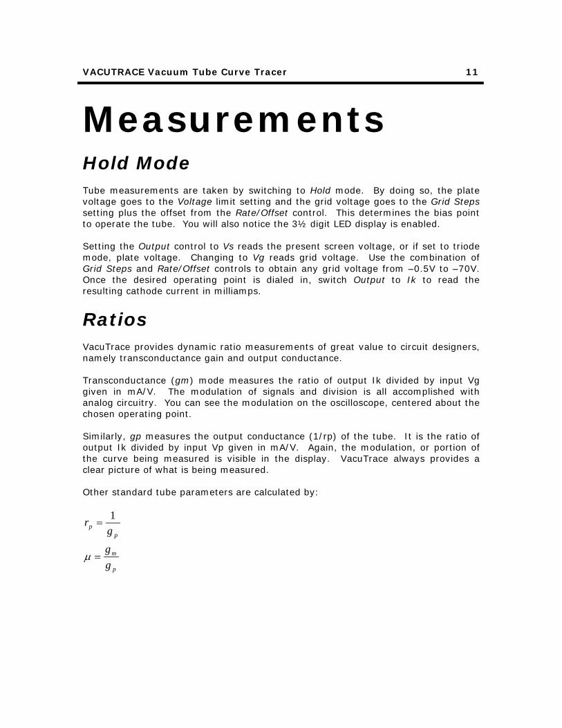
Ratios VacuTrace provides dynamic ratio measurements of great value to circuit designers, namely transconductance gain and output conductance. Transconductance (gm) mode measures the ratio of output Ik divided by input Vg given in mA/V. The modulation of signals and division is all accomplished with analog circuitry. You can see the modulation on the oscilloscope, centered about the chosen operating point. Similarly, gp measures the output conductance (1/rp) of the tube. It is the ratio of output Ik divided by input Vp given in mA/V. Again, the modulation, or portion of the curve being measured is visible in the display. VacuTrace always provides a clear picture of what is being measured. Other standard tube parameters are calculated by:
p
m
pp
gg
gr
=
=
µ
1
VACUTRACE Vacuum Tube Curve Tracer
12
Technology
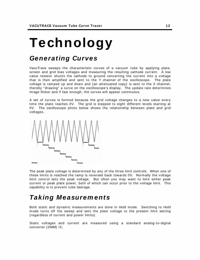
Generating Curves VacuTrace sweeps the characteristic curves of a vacuum tube by applying plate, screen and grid bias voltages and measuring the resulting cathode current. A low value resistor shunts the cathode to ground converting the current into a voltage that is then amplified and sent to the Y channel of the oscilloscope. The plate voltage is ramped up and down and (an attenuated copy) is sent to the X channel, thereby “drawing” a curve on the oscilloscope’s display. The update rate determines image flicker and if fast enough, the curves will appear continuous. A set of curves is formed because the grid voltage changes to a new value every time the plate reaches 0V. The grid is stepped to eight different levels starting at 0V. The oscilloscope photo below shows the relationship between plate and grid voltages.
The peak plate voltage is determined by any of the three limit controls. When one of these limits is reached the ramp is reversed back towards 0V. Normally the voltage limit control sets the peak voltage. But often you may want to limit either peak current or peak plate power, both of which can occur prior to the voltage limit. This capability is to prevent tube damage.
Taking Measurements Both static and dynamic measurements are done in Hold mode. Switching to Hold mode turns off the sweep and sets the plate voltage to the present limit setting (regardless of current and power limits). Static voltages and current are measured using a standard analog-to-digital converter (DMM) IC.

VACUTRACE Vacuum Tube Curve Tracer
13
In gm (transconductance) mode, a 625Hz modulation is added to the grid output. The dynamic peak-to-peak grid voltage is used as the reference for the LED analog-to-digital converter and the resulting cathode current modulation (just the ac component) is used as the input. This creates an analog divider circuit to calculate ∂Ik/∂Vg, which is transconductance gain. Similarly, in gp mode, the plate voltage is modulated and dynamic cathode current measured to determine output conductance.

VACUTRACE Vacuum Tube Curve Tracer
14
Miscellaneous
Tube Life Always set the plate voltage limit to minimum before coming out of standby. Do not turn up the plate voltage until the heaters have warmed up, otherwise you could cause cathode-stripping damage. Be careful not to exceed any of the tube’s maximum operating specifications. VacuTrace can deliver a lot of voltage, current and power to a tube. Small signal types such as a 12AX7 are vulnerable to such overdrive. It is not necessary to turn off VacuTrace when swapping tubes or socket adapter cards. That is what standby mode is for. All signals to the output connector are shut off in standby and it is safe to change tubes.

VACUTRACE Vacuum Tube Curve Tracer
15
Troubleshooting Problem Possible Causes/Solutions Does not turn on. Power cord not plugged in or fuse blown. Power switch
on rear panel must be turned on.
Tries to turn on but does not operate correctly.
AC input voltage selection on wrong setting.
LED display does not work.
VacuTrace must be in Hold mode.
Curves not generated. Faulty tube. Oscilloscope not in XY mode or set up improperly. Heater not warmed up yet. VacuTrace in Stby or Hold modes.
Oscilloscope display is backwards.
XY cables are reversed.
Curves keep disappearing.
VacuTrace is in an overload condition, lower the plate or screen voltage or remove fault.

A A
B B
C C
D D
E E
F F
G G
55
44
33
22
11
AC Voltage Select Board
N
Ac Switch
Ac Input
Blu
Blu/Yel
Brn/Yel
Brn
Blk
Blk/Red
Wht/Blk
Wht
E
Blu
Brn
Gry
Red
Vio
Red/Yel
Red
Yel
Yel
Yel/Blk
Grn
Grn
Grn/Yel
Grn/Y
Grn/Y
LL
ES
Blu/Yel
Brn/Yel
Blu
Brn
Blk
Blk/Red
Wht/Blk
Wht
100V
110V
120V
200V
220V
240V
NC
NC
NCNC
NCNC
NC
NC
NC
NC
NCNC
NCNC
NCNC
NC
NC
NCNC
NCNC
NC
NC
NCNC
SS
S SS
S
LL
L
LL
L
LL
L NN
NN
NNN
NN
AC Voltage Select
N
275Vrms @150mA
5Vrms @3A
6.3Vrms @5A
6.2V @1A
1.275V
This document contains proprietary information and except with written permission
of Hagerman Technology LLC such information shall not be published, or disclosed to
others, or used for any purpose, and the document shall not be copied in whole or in
part. Copyright Hagerman Technology LLC 2000. All rights reserved.
-5.65V @14mA
n/a
A
Va
cuT
rac
e: P
ow
er S
upp
ly
Ha
ge
rma
n Te
chn
olo
gy
LLC
P.O
. Box
264
37H
onol
ulu,
HI 9
6825
18
Tues
day,
Aug
ust 2
2, 2
000
Titl
e
Siz
eD
ocum
ent N
umbe
rR
ev
Dat
e:S
heet
of
D1
1N40
07
C2
100u
450V
C4
10n
500V
D3
1N40
07
D2
1N40
07
C3
100u
100V
C8
22u
10V
C6
10m
10V
T1
370F
X
C10
470u
10V
C11
22u
10V
ICL7
660
U2
V+8
C+
2O
UT
5
GN
D 3
C-
4
S 6
C7
10u
10V
C9
470u
10V
C1
10n
500V
C5
100n
50V
R1
4k7
1/2W
R3
4k02
1% R6
1k 1%
J32
J33
J34
J36
J35
J25
J26
J27
J28
J29
J30
J31
J23
J22
J24
J11
J12
J14
J15
J16
J17
J18
J19
J20
J21
J13
D4
1N40
07
D7
1N40
07 D
5
1N40
07
D6
1N40
07
R2
10 R
4
10
TP
1
R5
100
LM29
41
FB
1
IN4
OU
T5
GN
D 3
/EN
2
TP
2
TP
3
ICL7
660
U19
V+8
C+
2O
UT
5
GN
D 3
C-
4
S 6
C50
10u
10V
+400
V
-70V
+5H
-5H
5CT
+6V
-6V
10kH
z
-6H
+6H
+8V

A A
B B
C C
D D
E E
F F
G G
55
44
33
22
11
0V to 400V @200mA
10mV/VGDS
200mV/W
-5.65V
n/a
A
Va
cuT
rac
e: P
late
Am
p
Ha
ge
rma
n Te
chn
olo
gy
LLC
P.O
. Box
264
37H
onol
ulu,
HI 9
6825
28
Tues
day,
Nov
embe
r 14
, 200
0
Titl
e
Siz
eD
ocum
ent N
umbe
rR
ev
Dat
e:S
heet
of
+400
V
+6V
-6V
+6V
-6V
+6V
+6V
+6V
+6V
-6V
-6V
+6V
-6V
+6V
-6V
+6V
C14
100p
LM35
8
U3B 56
7
48
Q3
ZT
X55
8
Q6
2N39
04
Q8
ZT
X45
8
Q9
2N39
04
J1 Soc
ket B
oard
1 2 3 4 5 6 78 9 10 11 12 13 14
R19
16 1/2W
R7
1k
R13
100k
5W
R31
2k
R35
100k
1%
R42
100k
1%
R39
4k99
1%
R15
249k
1% 1/4W
R10
249k
1% 1/4W
R33
249k
1% 1/4w
R34
249k
1% 1/4w
R24
6k49
1%
R22
2k
Q1
2N39
06
C16
100n
C17
100n
C13
10u
10V
R25
100k
1%
R43
100k
1%
U5B
LM13
700
1116
9
1012
131514
6
Q5
IRF
820
R18
4k7
R14
470
Q4
IRF
820
R20
16 1/2W
R17
10k
R12
470
D8
1N52
37B
8V2
R9
10k
Q2
ZT
X55
8
R11
100k
C12
2p2
500V
R8
3R0
1/4W
Q7
ZT
X55
8
R16
100k
R27
6k49
1%
R29
20k0
1%
R23
100
LM35
8
U4A 32
1
48
R38
10k
R30
100
R26
2k
R28
47k
R21
10k0
1%
R32
10k0
1%
LM39
3
U6B
567
48
LM39
3
U6A
321
48R
40
100
C15
1u
R41
402k
1%
R36
402k
1%
R37
470k
R45
402k
1% R44
402k
1%
D10
1N41
48 D
11
1N41
48
D12
1N41
48
R47
10k
R46
100k
1%
LM35
8
U3A
321
48
TP
4
D33
1N52
26B
3V3
Q36
ZT
X45
8
R16
4
10k
R16
5
10k
Q35
ZT
X45
8
Q37
2N39
06
Sat
urat
e
Vpl
ate
Pla
teS
cree
n
Grid
AG
ridB
+6H
R
5CT
+5H
R-5
H
IkA
IkB
Cau
tion
Pla
te
-6H
Shu
tdow
n
Pm
od
Xsc
reen
IkA
IkB
Sta
ndby
Gre
en
Red
+8V
Ram
p
Ble
eder

A A
B B
C C
D D
E E
F F
G G
55
44
33
22
11
SCREEN
TRIODE/PENTODE
1 32
4 6 8
R L
CW
10mV/V
100V to 300V @25mA
n/a
A
Va
cuT
rac
e: S
cre
en
Am
p
Ha
ge
rma
n Te
chn
olo
gy
LLC
P.O
. Box
264
37H
onol
ulu,
HI 9
6825
Cus
tom
38
Frid
ay, D
ecem
ber
22, 2
000
Titl
e
Siz
eD
ocum
ent N
umbe
rR
ev
Dat
e:S
heet
of
+6V
-6V
+400
V
Q12
ZT
X45
8
R49
1M
P2
J2
J2
P2
S1
LM35
8
U4B
567
48
R51
470k
1/4W
R48
22k
1W
R52
220
1/4W
R55
249k
1% 1/4W
R57
249k
1% R59
4k99
1% Q10
IRF
820
D13
1N52
37B
8V2
R54
100
R56
100
C18
3u3
450V
R58
10k
TP
5
R16
6
10k
R17
2
100
1/2W
D13
1N47
61A
75V
1W D13
1N47
61A
75V
1W D13
1N47
61A
75V
1W D13
1N47
61A
75V
1W
Scr
een
Ble
eder
Pla
te
Vsc
reen
Shu
tdow
nX
scre
en

A A
B B
C C
D D
E E
F F
G G
55
44
33
22
11
n/a
A
Va
cuT
rac
e: G
rid C
ont
rol,
Mo
dul
atio
n
Ha
ge
rma
n Te
chn
olo
gy
LLC
P.O
. Box
264
37H
onol
ulu,
HI 9
6825
48
Frid
ay, A
ugus
t 18,
200
0
Titl
e
Siz
eD
ocum
ent N
umbe
rR
ev
Dat
e:S
heet
of
+6V
+6V
+6V
+6V
+6V
+6V
+6V
+6V
+6V
+6V
+6V
+6V
+6V
U8B
CD
4520
B
CK
9
EN
10
R15
Q3
14V
+16 V- 8
Q2
13
Q1
12
Q0
11
U7D
CD
4081
B
14
11
7
1312
U9A
CD
4001
B
14
3
7
21
U8A
CD
4520
B
CK
1
EN
2
R7
Q3
6V
+16 V- 8
Q2
5
Q1
4
Q0
3
U9C
CD
4001
B
14
10
7
98
U9D
CD
4001
B
14
11
7
1312
U7C
CD
4081
B
14
10
7
98
U9B
CD
4001
B
14
4
7
65
U7B
CD
4081
B
14
4
7
65
U7A
CD
4081
B
14
3
7
21
C22
1u C23
1u
R61
100k
1%
R62
10k0
1%
R60
2M
R16
7
10k
R16
8
10k
Bot
tom
Grid
2G
rid1
Grid
0
Clo
ckA
B
Grid
3
Hol
d
10kH
z/G
p
Diff
Pm
od
Gm
od
Sin
gle
/Gm

A A
B B
C C
D D
E E
F F
G G
55
44
33
22
11
0V to -70V @5mA
ECB
2 5
4
GRID STEPS
5
0.5
1 10
12
3
0V to -70V @5mA
ECB
2 5
7
GRID STEPS
6
0.5
1 10
10
98
5V
2V
1V
0.5v
1.2V
n/a
A
Va
cuT
rac
e: G
rid A
mp
s
Ha
ge
rma
n Te
chn
olo
gy
LLC
P.O
. Box
264
37H
onol
ulu,
HI 9
6825
58
Mon
day,
Oct
ober
09,
200
0
Titl
e
Siz
eD
ocum
ent N
umbe
rR
ev
Dat
e:S
heet
of
+6V
+6V
-70V
-6V
+6V
+6V
+6V
-6V
+6V
+6V
C32
220p
Q13
2N39
06
Q15
2N39
06
Q19
MJE
340
Q23
MJE
350
D20
1N40
07
Q25
MP
SA
42Q
27
2N39
04
R69
100k
1% R72
200k
1% R75
402k
1% R67
402k
1% R63
60k4
1% R88
100
R93
100
R97
4k7
R77
649k
1%
R81
100
R96
100k
Q21
2N39
06R
92
1k
D15
1N41
48 D
18
1N41
48
R65
200k
1%
D14
1N41
48
R82
2k
R71
10k
U10
A
LM13
700
111
8
75
423
6
D16
1N41
48
R86
71k5
1%
C34
470p
R78
649k
1%
C30
220p
R90
34k0
1% 1/4W
C26
47p
R84
162k
1%
C28
100p
P3
S2A
J3
C33
220p
Q14
2N39
06
Q16
2N39
06
Q20
MJE
340
Q24
MJE
350
D21
1N40
07
Q26
MP
SA
42
R70
100k
1% R74
200k
1% R76
402k
1% R68
402k
1% R64
60k4
1% R89
100
R95
100
R98
4k7
R79
649k
1%
Q22
2N39
06R
94
1k
D17
1N41
48 D
19
1N41
48
R66
200k
1%
R73
10k
U10
B
LM13
700
1116
9
1012
131514
6
R87
71k5
1%
C35
470p
R80
649k
1%
C31
220p
R91
34k0
1% 1/4W
C27
47p
R85
162k
1%
C29
100p
P3
S2B
J3
Q18
MP
SA
92
R83
100
C25
100n
C24
100n
TP
6
TP
7
Q34
2N39
04
R16
3
100k
Q39
MP
SA
92
C51
22p
C52
22p
Q17
MP
SA
92
Q38
MP
SA
92
Grid
A
Grid
2
Grid
1
Grid
0
Grid
3
Rat
e
Hol
d
A/B
Gm
od
IkA
Grid
B
Grid
2
Grid
1
Grid
0
Grid
3
Rat
e
Hol
d
B/A
Gm
od
Shu
tdow
n
IkB
Shu
tdow
n

A A
B B
C C
D D
E E
F F
G G
55
44
33
22
11
200mV/W
VOLTAGE
CURRENT
POWER
SWEEP/HOLD
RATE/OFFSET
CW
CW
CW
CW
R L
1 2 3 4 5 6 7 8 9
123456
0V to 4V
(10)
n/a
A
Va
cuT
rac
e: L
imits
, Osc
illa
tor
Ha
ge
rma
n Te
chn
olo
gy
LLC
P.O
. Box
264
37H
onol
ulu,
HI 9
6825
68
Wed
nesd
ay, S
epte
mbe
r 20
, 200
0
Titl
e
Siz
eD
ocum
ent N
umbe
rR
ev
Dat
e:S
heet
of
+6V
+6V
+6V
+6V
+6V
+6V
+6V
+6V
+6V
+6V
-6V
+6V
+6V
+6V
+6V
-6V
-6V
+6V
+6V
C36
220n
Q28
2N39
04
Q32
2N39
06
LM39
3
U11
B
567
48
R10
3
10k
P4
J4
LM39
3
U11
A
321
48
R10
5
10k
P4
LM39
3
U12
A
321
48
R11
0
10k
P4
J4
Q29
2N39
06
J34
R10
4
10k
P7
S3
P5
J32
R11
9
20k0
1%
R10
0
2k
R99
10k
R11
1
100
R11
7
13k0
1%
R11
6
10k0
1%
R12
0
10k0
1%
R11
5
249k
1% 1/4W
R11
4
249k
1% 1/4W
R10
1
4k7
R10
2
10k
C38
100n
C37
100n
U5A
LM13
700
111
8
75
423
6
Q31
2N39
04
R10
7
10k
R10
6
47k
J4
U13
A
CD
4013
B
D5
CLK
3
S6
R4
Q1
/Q2
V+14 V- 7
Q30
2N39
06
R11
3
1k
R10
8
10k
R10
9
10k
R11
2
1k
U14
A
LM13
700
111
8
75
423
6
U14
B
LM13
700
1116
9
1012
131514
6
LM39
3
U12
B 567
48R
118
10k
C39
100n
R20
0
100k
Sat
urat
e
Vpl
ate
Vca
thod
e
Pla
te
Vca
thod
e
Rat
e
Hol
d
Ram
p
Bot
tom

A A
B B
C C
D D
E E
F F
G G
55
44
33
22
11
50mV/V
40mV/mA
100mA = 2V
TUBE SELECT
TUBE SELECT
ZOUT
5 6STBY
A A/B
B 2A
STBY
A A/B
B 2A
7 81 2 3 4 5 (6)
n/a
A
Va
cuT
rac
e: A
/B, C
ath
od
es
Ha
ge
rma
n Te
chn
olo
gy
LLC
P.O
. Box
264
37H
onol
ulu,
HI 9
6825
78
Wed
nesd
ay, S
epte
mbe
r 20
, 200
0
Titl
e
Siz
eD
ocum
ent N
umbe
rR
ev
Dat
e:S
heet
of
+6V
+6V
+6V
+6V
-6V
+6V
+6V
-6V
+6V
+6V
+6V
+6V
-6V
S4A
D22
1N41
48
P6
J6
J39
S3
Rel
ay
32
4
8 1
5
76
D25
1N41
48
S4B
LM35
8
U16
B
567
48
P6
J6
U15
C
CD
4066
B14
9
7
6 8
D24
1N41
48
D23
1N41
48
R12
2
1k
R12
4
10k
R12
5
10k
R12
6
10k
R12
3
10k
R14
1
20R
03W 1%R
136
20R
03W 1%
R13
8
10k0
1%
R13
7
10k0
1%
R12
8
200k
1% R13
2
200k
1%
R13
4
200k
1%
R13
5
10k0
1% J7P
7
R12
1
10k
U15
D
CD
4066
B14
10
7
12 11
U13
B
CD
4013
B
D9
CLK
11
S8
R10
Q13
/Q12
V+14 V- 7
U15
A
CD
4066
B14
2
7
13 1
U15
B
CD
4066
B14
3
7
5 4
R14
0
10k
R13
9
100
R12
9
10k0
1%
R13
0
100
LM35
8
U16
A
321
48
R13
3
10k
Q33
2N39
04
R16
9
10 1/2W
C53
100n
C54
100n
A/B
Clo
ckA
B
48kH
z
B/A
Sta
ndby
+6H
R
+5H
R
IkB
IkA
Vca
thod
e
A/B
B/A
Grid
A
Grid
B
Vgr
id
+5H
+6H
A/B
B/A

A A
B B
C C
D D
E E
F F
G G
55
44
33
22
11
XOUT
YOUT
OUTPUT
OUTPUT
OUTPUT
1 2 3 4 5 6 7 8 9 10111213
1 2 3 4 5 6 7 1213
Vs
Vs
Vs
Vg
Vg
Vg
Ik
Ik
Ik
gm
gm
gm
gp
gp
gp
OUTPUT
Vg
Ik
gm
gp
14151617
Vs
3 4 1 2
500mV nominal
8 9 1011
141516
18
n/a
A
Va
cuT
rac
e: O
utp
ut, L
EDs
Ha
ge
rma
n Te
chn
olo
gy
LLC
P.O
. Box
264
37H
onol
ulu,
HI 9
6825
88
Mon
day,
Oct
ober
09,
200
0
Titl
e
Siz
eD
ocum
ent N
umbe
rR
ev
Dat
e:S
heet
of
+6V
-6V
+6V
+6V
+6V
+6V
+6V
-6V
R14
6
100k
D28
LED
Yel
low
R14
4
470
S5C
S5B
C45
220n
D30
1N40
07
D32
MS
Q64
10C V4
32
A1
20
B1
19
C1
17
D1
15
E1
14
F1
21
G1
16
P1
18
V3
31
V2
23
V1
22
A2
25
B2
24
C2
12
D2
11
E2
10
F2
27
G2
26
P2
13
A3
29
B3
28
C3
8
D3
6
E3
5
F3
30
G3
7
P3
9
A4
34
B4
33
C4
3
D4
2
E4
1
F4
36
G4
35
P4
4
C40
22u
10V
C46
220n
D27
1N40
07
C41
100p
J10
J8
C43
220n
J1
0
R15
0 100k
J9C
48
22u
10V
D26
1N41
48 D
29
1N41
48
P8
J9J9J1
0S
5A J8
P8
J43
J7
P7
P7
J7J5
2
J10
S5D
R16
1
470
R16
2
470
R16
0
470
J10
J10
J9
J10
J9J9
D31
LED
R/G
J9
R14
3
470
R14
2
470
U17
A
CD
4066
B14
2
7
13 1
C44
220n
U17
B
CD
4066
B14
3
7
5 4
R14
8
47k
U17
C
CD
4066
B14
9
7
6 8
U17
D
CD
4066
B14
10
7
12 11
R15
3
47k
R15
1
100k
R15
9
1k00
1%
R14
5
100k
C47
220n
C49
220n
C42
220n
R15
6
19k1
1%
R15
2
5k90
1%
R15
8
1k00
1%
R15
7
1k00
1% R15
4
1k00
1% J8J8
R14
9
1k00
1% R14
7
11k5
1%
U18
ICL7
107
CA
P+
34
TS
T37
IN-
30
V+1
V- 26
RE
F-
35R
EF
+36
O3
38O
239
O1
40
BU
F28
CO
M32
IN+
31
INT
27
D1
2
AZ
29
CA
P-
33
GN
D 21
C1
3B
14
A1
5
F1
6
G1
7
E1
8
D2
9C
210
B2
11A
212
F2
13E
214
D3
15
B3
16
E3
18
AB
419
PO
L20
G3
22
A3
23
C3
24
G2
25
F3
17
J8J8
R17
0
47k
R17
1
47k
R15
5
9k09
1%
Cau
tion
Gre
en
Vpl
ate
Red
Vgr
id
Vca
thod
eV
grid
Vsc
reen
Vgr
id
Vca
thod
e
/Gm
/Gp
48kH
z
Hol
d
Sin
gle
Diff
Sin
gle
Diff
Vsc
reen

A A
B B
C C
D D
E E
F F
G G
55
44
33
22
11
12V
6V
NC/-6H
IkB
GridB
Plate
-6H/+6H
+6H
IkA
GridA
Plate
Plate
IkB
+6H
-6H
GridA
Plate
IkA
GridB
+5H
-5H
Plate
GridA
Plate
Plate
+5H
-5H
2A3
300B
GridA
Plate
IkA
Screen
+6H
-6H
GridB
Plate
IkB
Screen
+6H
-6H
n/a
A
Va
cuT
rac
e A
da
pte
r: D
uals
, Oc
tals
, Po
we
r
Ha
ge
rma
n Te
chn
olo
gy
LLC
P.O
. Box
264
37H
onol
ulu,
HI 9
6825
99
Frid
ay, A
ugus
t 18,
200
0
Titl
e
Siz
eD
ocum
ent N
umbe
rR
ev
Dat
e:S
heet
of
100
100
100
0R62
1W 0R62
1W
100
6SN
7
1 2 3 4 5 6 7 8
5Y3
1 2 3 4 5 6 7 82A3/
300B
1 2 3 4
100
0R5
5W 0R5
5W
Soc
ket B
oard1 2 3 4 5 6 78 9 10 11 12 13 14
6L61 2 3 4 5 6 7 8
6L61 2 3 4 5 6 7 8
100
100
100
100
12A
X7/
6DJ8
1 2 3 4 5 6 7 8 9
Pla
te
IkB
+6H
-6H
Grid
A
Grid
B
Scr
een
IkA
IkB
Grid
A
+6H
-6H
5CT
Gnd
+5H
-5H
Pla
te
Pla
te
5CT
+5H
-5H
Grid
A
IkA
Grid
B
IkA
Scr
een
IkB
-6H
Grid
A
Grid
B
IkA
+6H
Pla
te