v90 plus gnss rtk system getting started€¦ · v90 plus gnss rtk system getting started 8. sd...
TRANSCRIPT

V90 Plus GNSS RTK System Getting Started
Hi-Target Co., Ltd
All Rights Reserved
Surveying Instrument
V90 Plus GNSS RTK System Getting Started

Content
1. Products Introductions
1.1 Preface
1.2 Product characteristics
1.3 Introductions to V90 Plus GNSS receiver
1.4 Introductions to iHand20 controller
1.5 Cautions for use
2. Basic Operation
2.1 Button operation
2.2 LED indicator lamp
2.3 WIFI password setting
2.4 Static data collecting (By button operation)
3. Hi-Survey
3.1 Project settings
3.2 Data collecting
3.3 Staking out
3.4 Data exporting
3.5 Auto-backup function in Hi-Survey
4. Simplified Operation of SurvCE
-------------------------------------------------------------------------------- 2
------------------------------------------------------------------------------------------------- 3
---------------------------------------------------------------------------- 3
----------------------------------------------------- 5
-------------------------------------------------------------- 9
------------------------------------------------------------------------------------ 19
---------------------------------------------------------------------------------------- 20
------------------------------------------------------------------------------------ 21
--------------------------------------------------------------------------------- 22
---------------------------------------------------------------------------- 23
-------------------------------------------------- 24
------------------------------------------------------------------------------------------------- 26
------------------------------------------------------------------------------------- 27
-------------------------------------------------------------------------------------- 54
------------------------------------------------------------------------------------------- 70
--------------------------------------------------------------------------------------- 89
------------------------------------------------------------- 91
------------------------------------------------------------------- 96
V90 Plus GNSS RTK System Getting Started
I

5. Trouble Shooting
5.1 Reset operation
5.2 Restore the iHand20 to factory settings
5.3 USB virtual serial port driver installation
5.4 Firmware update
5.5 Modify PCC radio with GM-xxPx management software
6. Technical Parameters
6.1 GNSS receiver
6.2 Communication
6.3 Controller
7. Socket and Main Accessories
7.1 Preface
7.2 Difference antenna
7.3 Controller
------------------------------------------------------------------------------------- 104
----------------------------------------------------------------------------------- 105
----------------------------------------------------- 105
---------------------------------------------------- 107
---------------------------------------------------------------------------------- 110
-------------------------------- 110
------------------------------------------------------------------------------- 114
------------------------------------------------------------------------------------ 115
------------------------------------------------------------------------------------ 117
------------------------------------------------------------------------------------------- 118
-------------------------------------------------------------------- 121
---------------------------------------------------------------------------------------------- 122
------------------------------------------------------------------------------- 122
------------------------------------------------------------------------------------------- 123
II
V90 Plus GNSS RTK System Getting Started

1
Preface
Exclusions
Before using the products, please carefully read the operating instruction, and it will help you better
use the product. Hi-Target Surveying Instrument Co., Ltd will not assume the responsibilities if you
fail to operate the product according to the requirements in operating instruction, or operate the
product wrongly because of failing to understand the operating instruction.
Hi-Target is committed to constantly perfect product functions and performance, improve service
quality and reserve the rights to change the contents in operating instruction without separate notice.
We have checked the consistency between contents in instruction and software & hardware. Pictures
in operating instruction are only used for reference.
In order to help you better use Hi-Target series products, Hi-Target suggests you carefully reading
the instruction. If you are unfamiliar with V90 Plus products, please refer to
www.hi-target.com.cn/en/
Tips for safe use
Note: the contents here are generally special operations, needed to paid
special attention on. Please read the contents carefully.
Warning: the contents here generally are very important so please read
it carefully in case of failing to operate based on warning contents which
would damage the machine, lose the data, break down the system and
bring risk to user’s health.
V90 Plus GNSS RTK System Getting Started

2
Products Introductions■ Preface
■ Product characteristics
■ Introductions to V90 Plus GNSS receiver
■ Introductions to iHand20 controller
■ Cautions for use
Products Introductions
CCCC HHHH AAAA PPPP TTTT EEEE RRRR
1

3
V90 Plus GNSS RTK System Getting Started
1. Products Introductions
1.1 Preface
Small and lightweight
◇Only weighs 950g.
◇Measures Diameter 153mm x Height 83mm.
Multi-constellation Tracking
◇220 tracking channels
◇Supports GPS, GLONASS, GALILEO, BDS, SBAS
◇NGS approved full-band GNSS antenna
1.2 Product characteristics
V90 Plus is a new type of GNSS receiver used for measurement pushed forward by Hi-Target
recently. With a hi-tech, fully integrated design, the conveniently sized V90 Plus is one of the most
flexible choices for any measuring task. Built-in Linux3.2.0 operating system, pre-loaded multiple
smart applications such as tilt surveying, electronic bubble calibration, NFC and voice DIY, LEDs
enable you to monitor satellite tracking, radio reception, data logging status, Wi-Fi status, and
power. Bluetooth wireless technology provides cable-free communications between the receiver and
controller.V90 Plus GNSS system provides surveyor industry-leading GNSS solutions.
Warning:
the instruction represents no standard configuration. The articles within the box can be adjusted
according to different user requirements. The specific configuration shall be subject to the outgoing
list upon purchasing. The suggestions before using the machine: check whether the product package
is damaged; please open the package carefully and confirm whether the articles are consistent with
outgoing list; in case of loss or damage in the product and its accessories, please immediately contact
with local office or dealers; please carefully read the operating instruction before carrying,
transporting and using the product.

4
Products Introductions
Smart Application
◇Offers tilt survey with a maximum tilt angle of 30 degrees.
◇Supports electronic bubble calibration
◇The internal NFC module makes Bluetooth communication quick and easy.
◇Intelligent voice assistance guides field operations. Voice can be DIY.
◇Standard Rinex data and HI-TARGET raw data recorded simultaneously.
Optional Transceiver UHF Radio
◇The transceiver UHF radio enables switchable working modes between base and rover.
◇Three types of internal UHF radio provide different frequencies based on users requirements. The
Pacific Crest TrimTalk© internal UHF radio is compatible with other radios.
Multi-network Connection
◇Powered by high-capacity (5000mAh) Li-ion battery to ensure full day operation
◇Supports WIFI
Powerful Battery
◇Powered by high-capacity (5000mAh) Li-ion battery to ensure full day operation
Rugged Design
◇IP67 dustproof and waterproof
◇Able to survive a 3-meter natural fall onto concrete

5
V90 Plus GNSS RTK System Getting Started
V90 Plus mainly consists of three parts, the upper cover, bottom cover and the control panel.
In the middle of the mainframe is the control panel which contains a power button and three indicator
lamps. The only power button can complete all function Settings and three indicator lamps are
satellite lamp (single green lamp), power lamp (bi-color lamp of red and green) and status lamp
(bi-color lamp of red and green) from the left to the right.
1.3 Introductions to V90 Plus GNSS receiver
Upper Cover
U-type anti-wear buffer can effective avoid the instrument from scratches.
Double-color model makes the structure clear and appearance beautiful.
Anti-wear Buffer
Double-color Model
Hardware Schematic Diagram
5
42
1
3
V90 Plus hardware structure
1. Guard Circle 2. Control Panel 3. 3G/UHF antenna interface
4. Bottom Cover 5. Upper Cover

6
1. USB interface and protective plug (it is used to export data and upgrade firmware)
2. Speaker (timely operate the instrument and broadcast the status with voice)
3. Metal buckle
4. Battery compartment
5. Connecting screw hole(it is used to fasten the instrument to base or centering rod)
6. 5-pin socket and protective plug (it is used to output NMEA -0183 and link external radio and
external power)
7. Antenna port and protective plug (Connect transceiver antenna for receiving and transmitting
differential signal.)
Products Introductions
Bottom
Inside of the battery compartment
4
11
10 98
7
2
1
Bottom Cover
6
5
3

7
V90 Plus GNSS RTK System Getting Started
8. SD card slot (it is used to place SD card, which can store massive static data)
9. SIM card slot power seat (when communicating with GSM data, it is used to place SIM card.)
10. Spring contacts (it is used to connect the lithium battery and host)
11. Battery cover
Cautions:
1. When 5-core socket is not in use, please cover them with the plug.
2. When water enters into the speaker, it is likely that the speaker is silent or hoarse. The voice can
recover after the speaker is dry.
Receiver equipped with UHF built-in radio antenna and 3G/GPRS antenna. According to
different work mode, select the right antenna type. When using the “UHF base station "/" UHF rover
station "mode, please use the UHF built-in radio antenna; when using the “GSM base station "/"
GSM rover station ", please use the 3G/GPRS antenna.
3G/GPRS antenna(short) UHF built-in radio antenna(long)
Antenna

8
Products Introductions
Batteries
The receiver has one rechargeable Lithium-ion battery, which can be removed for charging. You can
also connect the receiver to an external power source through 5-pin socket.
Recharge
BL-5000 lithium battery shall use Hi-Target CL-8410 lithium battery charger to charge. About 7
hours of charging time CL-8410 charger is designed with charge lamp. The lamp is red during
charging process and turns green upon finishing charging. The battery is full continue charging for
another 1-1.5 hours.
Positive pole
Negative pole
Charging lamp
Charging lamp

9
V90 Plus GNSS RTK System Getting Started
1.4 Introductions to iHand20 controller
Front of handheld controller
The front of iHand20 handheld controller includes touch screen, keyboard and microphone.
Touch screen: Multipoint capacitive touch screen with touch pen, which supports Chinese and
English input.
Keyboard: Photograph, direction control, switch between Chinese and English, data collection,
volume control, power on, power off and other functions.
Microphone: Internal microphone can be used for field collection of voice message.
Touch screen
Keyboard
MIC

10
Products Introductions
Reverse side of handheld controller
There are camera, battery cover, belt, trumpet, etc. on the reverse side of iHand20 handheld
controller.
Camera: Used for field collection of image information.
Battery cover: Internal removable lithium battery.
Belt Buckle: Connect the belt to prevent sliding down.
Speaker: Conduct real-time voice broadcast for the instrument operation and status.
SpeakerCamera
Battery cover
Belt Buckle
NFC Chip

11
V90 Plus GNSS RTK System Getting Started
Side of handheld controller
Mini USB: Used for connecting USB data line and iHand20 handheld controller.
Audio port: Used for connecting headphone cable and iHand20 handheld controller.
Warnings: In case of not using audio port or Mini USB, please close the rubber cover so as to
achieving waterproof and dustproof.
Handheld controller accessories
Charger
Fig.2- 3
Waterproof & dustproof rubber cover
Audio port
Mini USB

12
Products Introductions
Battery
Lithium battery: 3.7V /6300mAh
Data line
Connect to the USB port of computer, and used for download of data Connect to the USB port of
charger and used for charging handheld controller
Touch pen
In case of using touch pen to operate the handheld controller, it is required to start the function of
"handwriting pen", and open the handheld controller’s [system setting] → [auxiliary function] →
check [handwriting pen]

13
V90 Plus GNSS RTK System Getting Started
Operation of handheld controller
Keyboard
Most settings and operations of Hi-Target iHand20 handheld controller can be completed by the
touch pen, and commonly used operations can be completed by keyboard. Appearance and
functions of keyboard are introduced briefly as follows.
Keyboard include: Back, OK, Power, APP, Fn, Collect, Camera, etc. on button board of iHand20.
Back: Delete or exit the operation of current window.
OK: Confirmation.
Power: Press it for above 3s for power on/ power off/reboot. Under the power on status, press power
button for 1s to turn off / turn on the screen backlight. Press it for 10s to forced shutdown when
the controller is crash.
Back
Collect
OK
Del
Space
Enter
PowerCamera
Fn
APP
Menu
Home

14
Products Introductions
Cautions: When installing Hi-Survey Road for the first time, it is necessary to press key APP
for 3s for software quick start selection settings. Otherwise, corresponding software cannot be
started quickly by only pressing button APP.
Fn button: Press Fn button for 3s and popup interface of input method switch so as to achieve fast
switch of input method. In case of [physical button input method], only press Fn button to switch
over input methods of Chinese Pinyin ,strokes, digitals and letters under input status.
APP: Quick start of Hi-Survey software, press button APP for a long time for the Road popup, then
select "Hi-Survey Road" and click [Ok]. And the software selected this time can be started quickly
only by pressing key APP next time.

15
V90 Plus GNSS RTK System Getting Started
Collect button: Collect data by manual operation.
Camera button: Press it for a short time to enter into photograph interface; Press it for 3s on the
non-camera interface to start up/shut down flashlight function.
Screenshot function: Press "VOL-" and power button simultaneously for 3s, screen capture will be
kept in the file of "Mobile phone storage→ Pictures→ Screenshots".
Cautions:
1. When the iHand20 handheld controller is not used in the work, please turn off the backlight for
saving electric quantity and prolonging the working time.
2. Only the image collection interface supports the shortcuts operation. In order to avoid the input
conflict of input box, the text interface does not support shortcuts operation.
(1)Average collection shortcut is Key "7";
(2) Indirect measurement shortcut is Key "8".
Model of iHand20 handheld controller battery and charger
Name
Lithium battery
Charger
Model
BL-6300A
CL-6300A

16
Products Introductions
Data download
Connect handheld controller to computer
1. Connect handheld controller to computer by supporting USB data line, and pull down the notice
column and click USB computer connection [open USB storage].
2. If it is required to synchronously operate handheld controller or install and use third-party
software to debug data on the computer, "USB debugging" function shall be ticked. Turn on the
handheld controller, and click [System Settings]→[Developer options ]→[USB debugging] on the
desktop menu.

17
V90 Plus GNSS RTK System Getting Started
Click[System Settings]
[Developer options]

18
Products Introductions
[USB debugging]
3. In the popup debugging window, click [OK] to complete the connection between handheld
controller and computer.
4. In the computer, file operations between handheld controller and computer can be conducted by
[Portable Devices].

19
V90 Plus GNSS RTK System Getting Started
Environmental Requirements
The receiver shall operate in dry working environment regardless of waterproof materials. In order
to advance the stability and service cycle of receiver, the receiver shall be prevented from extreme
environment, such as:
◆Moisture
◆Temperatures above 65 degrees centigrade
◆Below - 40 degrees centigrade
◆Corrosive liquids or gases
Electronic Jamming
The receiver shall not be installed in the place near to strong electric power and interference signal,
such as:
◆Oil duct (spark plugs)
◆Generator
◆Battery-operated motor cycle
◆DC-AC power supply changeover equipment
◆Signal transmitting station (tower)
◆Power supply
Battery safety
Warnings:
1. Must use battery and charger configured by manufacturer, and do not throw them into the fire or
use the metallic short-circuit electrode.
2. For the first usage, there is a certain electric quantity in the battery generally. Therefore, the
battery shall not be charged until the electric quantity is used up. And it shall be charged for 12 hours
for the first three times and later it can be charged normally. Each charging time shall not be more
than 24 hours.
3. Do not use or charge the battery if it appears to be damaged. Signs of damage include, but are not
limited to, discoloration, warping, and leaking battery fluid.
4. If the service life of the battery is shortened obviously, please stop using the battery. It indicates
that the battery has been aged , please replace it with new one.
1.5 Cautions for use

20
Basic Operation
Basic Operation■ Button operation
■ LED indicator lamp
■ WIFI password setting
■ Static data collecting (By button operation)
CCCC HHHH AAAA PPPP TTTT EEEE RRRR
2

21
V90 Plus GNSS RTK System Getting Started
2. Basic Operation
2.1 Button operation
V90 Plus adopts optimized and simplified design,button operation with control panel is more
convenient and concise.
1. Control panel
Most settings and operations of V90 Plus Receiver can be conducted by power button, below is
control panel.
2. Button functions
Functions
Power on
Power off
Auto-set base
Work mode switch
Work mode confirmation
Reset main board
Mandatory power off
Differential signal lamp
Satellite lamp
Power lamp
Detailed description
Press power button for 1s to power on.
Long press power button (3s≤long press time≤6s) when voice
prompts "dingdong" and release button to power off.
In power off status, long press power button for 6s when voice
prompts "set base automatically", then release it ; the receiver
will automatically set base mode.
Double click power button enter work mode switch, every
double click will switch to another work mode .
Single click to confirm the current work mode
In power on status, long press power button for more than 6s
when voice prompts the second "dingdong", then release it .
In power on status ,long press power button for more than 8 s.

22
3. Power on/off
Press power button for 1s to power on. Long press power button (3s≤long press time≤6s) when voice
prompts "dingdong" and release button to power off.
4. Reset main board
In power on status, long press power button for more than 6s when voice prompts the second
"dingdong", then release it.
5. Auto-set base station
In power off status, long press power button for 6s when voice prompts "set base automatically",
then release it, the receiver will automatically set base mode.
2.2 LED indicator lamp
Basic Operation
Description
In normal voltage
Battery>7.6V
External power supply>12.6V
In normal voltage
7.2V<battery<7.6V
11V<external power supply<12.6V
Low voltage:battery≤7.2V
External≤11V
Power status hints: once or four times of one min
No GSM/WiFi connection
GSM/WiFi module connect to server successfully
GSM/WiFi module connect to internet
successfully
GSM/WiFi module is connecting to internet server
1.Receiving or transmitting data (only receiving
data for rover while transmitting for base)
2. collecting static data in static mode
Communication failure, no data output
Status
Always on
Always on
Slow flash
Fast flash
Off
Always on
Slow flash
Fast flash
Slow flash
Off
Lamp
Power lamp(yellow)
Power lamp(red)
Differential signal
lamp(green for
status)
Differential signal
lamp(red for status)

23
V90 Plus GNSS RTK System Getting Started
2.3 WIFI password setting
V90 Plus receiver can used as WiFi hotspot, support user-defined password (Factory default
password:12345678)
Cautions:
1.See WiFi factory default password in attached list1
2.If you forget your password, you can reset your password by”GNSS Receiver Manager V1.0.3”,
relative operation see in Appendix.
More than 4 satellites tracked successfully
Lose satellites and try re-track
1. mother board error resulting in no data output
while resetting receiver
2. mother board error resulting in no data output
while in static mode
Reset main board or static collecting error
(Insufficient storage space )
Always on
Slow flash
Off
Anomaly flash
of 3 lamps
Satellite led (green)

24
Basic Operation
2.4 Static data collecting
V90 Plus GNSS Receiver can collect static data. relative operations are as below.
1. Set up receiver on a control point, centering and leveling strictly.
2. Measure the height of receiver for three times, on condition that the difference of each measuring
is less than 3mm and the final height of the receiver should be the average height. Below is the
schematic.
Notice:
1. Instrument height should be measured from control point to the upper of measurement bench
marker.
2. The height of phase center is 0.1018 meter.
3. The measurement bench marker radius is 0.130 meter.
Below is the schematic.
Radius=13mm
Measurementbench marker
Phase conter=101.8mm
Measurement Bench Marker
Slant height---Measure from control point to upper measurement bench marker

25
V90 Plus GNSS RTK System Getting Started
3. Record point name, receiver S/N,receiver height ,beginning time.
4. Press power button to power on and double click power button to set static collecting mode; then
single click power button to confirm it.
Notice:
The satellite lamp flashing means the receiver is searching the satellites. The satellites are fixed once
the satellite lamp stays lit on. Status lamp flashes due to your collection interval set, which means a
epoch will be collected every flashes.
5. Turn off the receiver after static data collected and record the turn off time.
6. Download and post-process static data.
Caution:
Don’t move the tri-brach or change the collecting set while the receiver is collecting data.
V90 Plus default settings will not record Rinex format data .Users can change relative settings by
GNSS Receiver Manager software. Below is the GNSS Receiver Manager software interface.

26
Hi-Survey
Hi-Survey■ Project settings
■ Data collecting
■ Staking out
■ Data exporting
■ Auto-backup function in Hi-Survey
CCCC HHHH AAAA PPPP TTTT EEEE RRRR
3

27
V90 Plus GNSS RTK System Getting Started
3. Hi-Survey
3.1 Project settings
■ New project
■ Project settings
■ Device connecting
■ Base setting
■ Rove setting
1. New project
After new project is built before the measurement, the collected data will be saved in the project.
When building new project, relevant setting needs to be conducted, for example, setting of project
information, and coordinate system, etc..
Specific procedures as follows:
1.Single-click "Hi-Survey" to open it

28
Hi-Survey
2. Project settings
Project settings include coordinate system and other parameters settings.
2. "Project Info": New project can be
built and the existing project can be
opened or deleted.
3.Input project name in "Name"
box->click "OK";
(Note: The name of new project shall
not be the same as the name of old
projects)

29
V90 Plus GNSS RTK System Getting Started
For measurement, coordinate system must be configured, because it is related to the accuracy of
coordinate. There are two methods to set the coordinate system.
A. build a new coordinate system, including ellipsoid projection and ellipsoid transformation
parameters, etc.
B&C. Import existing coordinate system.
1.Click Project Settings:including
settings of project and coordinate
system information
2. Enter settings interface

30
Hi-Survey
A. Build a coordinate system
(1) Click "Projection"-> ->User Defined
Notice:Any question about “Users Defined” pleases contact technical support
1.Click " " to enter into the
setting interface.
2. User Defined: User can conduct
settings according to local parameter.

31
V90 Plus GNSS RTK System Getting Started
B. Add existing coordinate system files
1) Click " " ->Select .dam File; Click " " to return the parent directory. Path: SD Card
->ZHD->Geo Path ->select .dam file (take the addition of DD. dam for example) ->click "OK".
1. Click " "to add created dam
system file.
2. Select dam File ;click " "

32
Hi-Survey
C.Add coordinate system files (Hi-Survey software BYO)
The software adds many coordinate systems all over the world intelligently for reference and
selection.
4. Select coordinate system files,
with the suffix of .dam. And click
"OK" to complete the selection.
3. Click" " to return to the
parent directory.

33
V90 Plus GNSS RTK System Getting Started
3. Device connecting
V90 Plus as a new generation of intelligent GNSS receiver, its connection ways with iHand20
become various .receiver can connect iHand20 by Bluetooth or WiFi.
Notice:NFC used to quickly establish Bluetooth connection.
1.Return to " " interface
2. Click "Predefined" Select the
continent and countries where you
are located
3.select the file and Click "Apply" to
apply it current project.

34
1. Click "Device" to connect receiver
to handheld controller
2. Select the connection type "Bluetooth"
Hi-Survey
Bluetooth connection
Receiver is connected with handheld controller by Bluetooth, therefore, it is necessary to do this step
before the operation. If conducting RTK under the mode of UHF , two sets of receiver Bluetooth
shall be configured at least(one for Base and one for Rover).

35
V90 Plus GNSS RTK System Getting Started
3. Select S/N code of the device to be
connected->input Bluetooth
PIN"1234";
4. After connection, the interface will
display current work mode, firmware
version, firmware version of GPS
main -board and log-on message,
etc..

36
Hi-Survey
WiFi connection
V90 Plus can be connected with iHand20 by WiFi. Connection steps are as below.
1. Power on iHand20 and run Hi-Survey software.
2. Run V90 Plus WiFi function, and click "others".
3. Choose "Receiver Settings"
4. Launch Wifi;
5. Click "Device"->Choose "Wifi"->Click" Connect"
6. Launch iHand20 WiFi, and search receiver's WiFi name.
7. Choose receiver and input WiFi password(Note: Original password is 12345678), and click
"Connect".
8. iHand20 connect with receiver successfully.
9. Back to "Device" interface, Click "Connect"
10. Connected.
Notice:Before WiFi connecting , please connect receiver by Bluetooth and turn on the “WiFi
Swither” switch in Receiver Settings .
Only in Bluetooth connected mode that WiFi password can be modified.
Modify WiFi password procedure as below shows
1.Click "Others"->Receiver settings;
2. Choose "Wifi Hotsot Password Set";
3. Input "Old Password" and "New Password" and "Confirm New",Click "Set".
Notice: WiFi password can be modified.
Only in Bluetooth connected mode that WiFi password can be modified
NFC(Near Field Communication)
NFC used to quickly establish Bluetooth connection.
Steps.
1. Long press "APP" button.
2. Choose "Hi-Survey Road"->Click "NFC"->Click "OK".
3. Take iHand20 NFC response area close to receiver's NFC response area.

37
1. Long press "APP" button.
2. Choose "Hi-Survey Road"->Click
"NFC"->Click "OK".
Detail operations as below show V90 Plus GNSS RTK System Getting Started

38
Hi-Survey
3. Take iHand20 NFC response area close to receiver's NFC response area.
4. Base setting
Base operation guidelines
Base parameters settings in Hi-Survey
Base operation guidelines
For good performance, read the following guidelines, Below will describes best practices for setting
up the base, and outlines the precautions that users need to take to protect the GNSS receiver.
1. Set up tripod centered on the control point, mount tri-branch adaptor and height extension pole.
2. Screw GNSS receiver onto the height extension pole.
3. Level and plumb GNSS receiver over control point.
4. Instrument height should be measured from control point to the upper of measurement bench
marker. (See diagram in chapter 2)
Notice: Ensure to place the GNSS receiver in a stable and secure location, and make sure no
interference source disturb or disrupt differential signal transmission. Such as electrical tower etc..
Base parameters settings in Hi-Survey
(1) Connecting base
(2) Setting Base coordinate
(3)Setting data link
Setting parameter of Base after connected.
NFC response area

39
V90 Plus GNSS RTK System Getting Started
1.Open software "Main interface"
->Device
2.Confirm current connected GPS
receiver (take 11600002 for example)
Including: coordinate of Base, communication mode, difference scheme, etc.. Base is responsible for
transmitting difference to the Rover so as to conduct real-time kinematic. The Base can be set by
iHand20 after receiver Bluetooth has been connected.
(1) Connecting base

40
3. For example: Set 11600002 as
Base;
4. Select "type of antenna" ->input
"target height"(Target H)
Notes: Select type of antenna
according to the type of receiver
Hi-Survey
Notice:
Pole height ---Reading from scale of centering rod .
Slant height---Measuring from control point to Measurement bench marker.

Select "geodetic coordinates BLH" or
"local coordinates NEZ". (Take BLH
for example)
41
V90 Plus GNSS RTK System Getting Started
Slant height is normally used for the Base and pole height is commonly used for the Rover.
(2)There are three methods to set "coordinate of Base":
A. Input with known point.
B. Get by average.
C. Select from the point library;
A. Input with known point.
1) Ensure accuracy of coordinate of Base;
2) Select "geodetic coordinates BLH" or "local coordinates NEZ". (Take BLH for example)

1. Click" "
2. Click "OK" to obtain position of
Base.
42
Hi-Survey
B. Get by average
1) Click" "->Click "OK" to obtain position of Base.

1. Click" "
2. In the point library, there are
"original data" and "control point"
data, etc. for optional.
43
V90 Plus GNSS RTK System Getting Started
C. Obtain from point library

1. Click "Datalink"
2. There are 4 kinds of data chain,
which are Internal UHF, Internal
GSM, External Device and External
Network(3G).
44
Hi-Survey
(3) Set data chain, including
A. "Internal UHF", B."Internal GSM" (Omitted), C."External Device"
A. "Internal UHF"
1) Data link->select "Internal UHF"

Data-link : Internal UHF(for
example)
Channel: 0-116 channels
(DDTR-type instrument transceiver)
for optional, 0-32 channels (PCC
transceiver)
Sky Baud rate: Choosing transmit
rate at 19200 or 9600
Power: low, medium and high
power.
Difference mode
Including RTK, RTD and RT20.
RTK is defaulted and RTD refers to
code difference, Message
type(Message Type): RTCA, RTCM
(2.X), RTCM (3.0), CMR, NovAtel
and sCMRx
Elevation mask:can be adjustable
within 5-20 degrees.
(Base is in conformity with Rover)
45
V90 Plus GNSS RTK System Getting Started
2) Set "Chanel", "Sky Baud rate", "Power", etc.
Notice: Transceiver type, sky Baud rate and channel of Base and Rover must be same.
3) Other settings (including difference scheme and elevation cutoff angle, etc.)
Notice: sCMRx, RTCM3.2 support BDS differential signal .

46
Hi-Survey
Click "Set" to complete the setting of
Base
If the setting of Base is completed,
the software prompts "setting of
Rover".
4) Click "Set" to complete the setting of Base
C. "External Device"
1) Datalink-> select "External Device";

47
V90 Plus GNSS RTK System Getting Started
1. When Base data chain selects
"External Device", channel of
transceiver will be determined by the
external device.
2. Other settings Same as UHF
setting method.
3. Click "Set" to complete the setting
of Base.

48
Hi-Survey
1.Click "Yes" to jump to setting of
Rover
2.Click "Connect"
5. Rover setting
(1) After completing setting of Base, enter into "setting of Rover" ->select "Yes"->click "Connect"
to set the Rover.

49
V90 Plus GNSS RTK System Getting Started
If the device has not been equipped
with the Bluetooth, please refer to
above "Bluetooth connection"
method for configuration.
The connected instrument can
display fuselage number (Such as:
10211158)
(2) Click "Connect" and select receiver equipped with Bluetooth
(3) Set Rover "Data-link", including "Channel" and "Sky Baud rate", etc. and click "Set" to complete
the setting of the Rover.

50
Hi-Survey
Data-link: Internal UHF
Conformity with Base(take 6 for
example)
Conformity with Base(take 19200 for
example)
(4) When Base communicates with the Rover successfully and differential lamp (middle lamp) in
both Base and Rover flash red.
6. Floating box
"Solution state": It is mainly divided into the following several modes (except for fixed coordinate,
precision is arranged from high level to low level):The given point refers to fixed coordinate (Base)
→ RTK fixed solution → RTK float solution → RTD solution → single point positioning →no
solution type(indicates: no GNSS data)
Common Satellites-Satellites
PDOP value Correctionlatency
Solution Receiver power

51
V90 Plus GNSS RTK System Getting Started
"Correction latency": Refers to calculating time after Rover receives the signal from Base.
"PDOP value": Intensity factor of space geometry where the satellite is distributed. Generally, the
better the satellite distribution is, the smaller the PDOP value is. Generally, the value is less than 3
as the more ideal state.
"Number of visible satellites": Number of satellite received by receiver, at least 5 satellites required
by RTK work.
"Number of public satellites": Base hasn’t it and only Rover has it after receiving the difference data.
It refers to the satellite used for calculation when the Base and Rover participate in the searching of
ambiguity of whole cycles at the same time, which are generally more than 5 so as to ensure normal
work.
Click the satellite icon in the floating window to rapidly check detailed information of current
connected receiver satellite.
(1) Position information
Display position information of current point, including position, speed, solution state and time,
etc..

52
Hi-Survey
Satellite view
Input elevation cutoff angle in
"Elevation (。)" and click "Set" to
set the elevation cutoff angle of
receiving satellite.
(2) Stellar map
◇ Distribution situation of projection position of satellite can be viewed. Roundness refers to GPS
satellite and SBAS satellite, square refers to GLONASS and BDS satellite. GPS: Prn value is 1-32;
GLONASS: Prn value is 65-96; BDS: Prn value is 161-197.
◇ View elevation cut-off angle of GNSS satellite and click "Set" to set the elevation cutoff angle of
receiving satellite.
Click "Status", and give the color according to L1 carrier signal to noise ratio of satellite:
orange<=15, yellow<=35, green>35As shown in the following figure:

53
V90 Plus GNSS RTK System Getting Started
(3) Signal-to-noise ratio figure of satellite:
Prn refers to number of satellite; Azi refers to azimuth angle of satellite; Ele refers to satellite
elevation, L1 refers to signal to noise ratio of L1, and L2 refers to signal to noise ratio of L2.
Click "Status"
Click "SAT Info", and Prn refers to
number of satellite, L1 refers to
signal to noise ratio of L1, L2 refers
to signal to noise ratio of L2 .
54
Hi-Survey
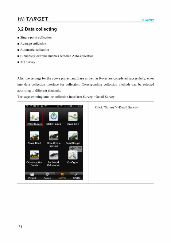
3.2 Data collecting
■ Single-point collection
■ Average collection
■ Automatic collection
■ E-bubble(electronic bubble) centered Auto-collection
■ Tilt survey
After the settings for the above project and Base as well as Rover are completed successfully, enter
into data collection interface for collection. Corresponding collection methods can be selected
according to different demands.
The steps entering into the collection interface: Survey->Detail Survey;
Click "Survey"->Detail Survey

55
V90 Plus GNSS RTK System Getting Started
Detail Survey
1. Single-point collection
Single-point collection means collecting the data of each point by manual operation.
(1) Click " "->" "
Click " "

56
Hi-Survey
(2) Input information of collection point, including point name, target height (the first point needs to
be measured and the next points can be defaulted) and point position description (non-input
optional).Click "OK" to complete the collection of the point.
Click " "
( Single Press " " on the keyboard
can also collect point )
Name: Input the point name.
57
V90 Plus GNSS RTK System Getting Started
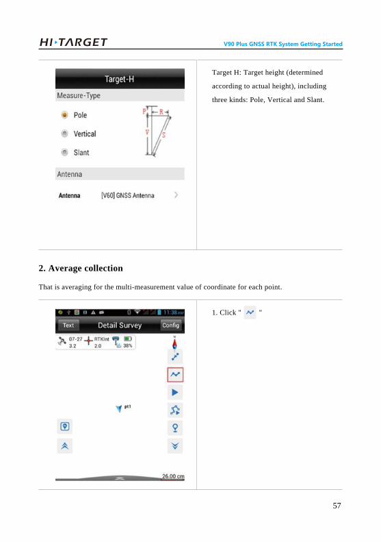
2. Average collection
That is averaging for the multi-measurement value of coordinate for each point.
1. Click " "
Target H: Target height (determined
according to actual height), including
three kinds: Pole, Vertical and Slant.
58
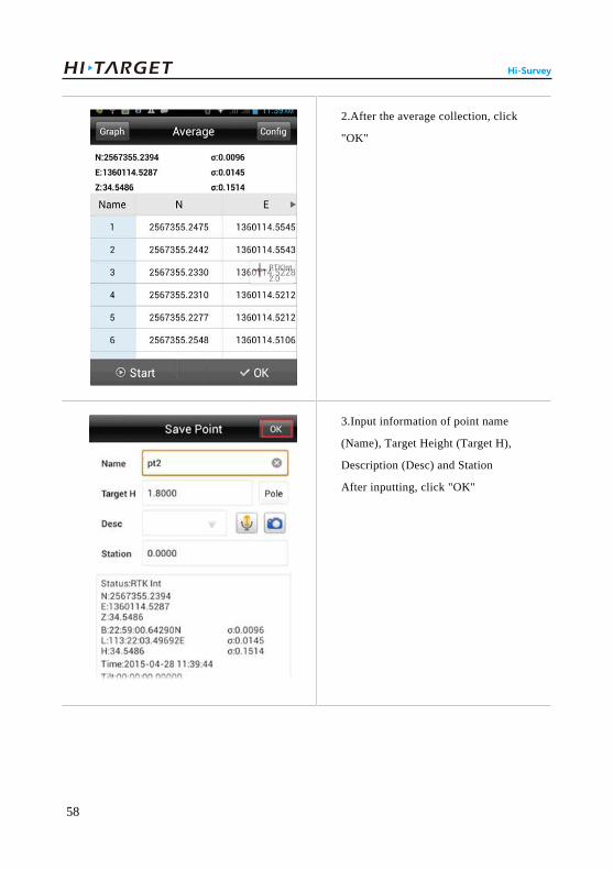
Hi-Survey
2.After the average collection, click
"OK"
3.Input information of point name
(Name), Target Height (Target H),
Description (Desc) and Station
After inputting, click "OK"

59
V90 Plus GNSS RTK System Getting Started
Setting method of average collection:
4.At the moment, the point will be
saved
1.Click "Config" to enter into
average collection setting interface.

60
Hi-Survey
3. Automatic collection
Point measurement will be recorded automatically according to the configured record condition.
1.Click " "to start automatic
collection.
2. Available to set the average times.

61
V90 Plus GNSS RTK System Getting Started
2. Collection setting, including
sampling interval (time or distance),
point name and number,
etc.(user-defined available)
3. Click "OK" to start collection.

62
Hi-Survey
4. E-bubble centered Auto-collection
When users open the electronic bubble calibration function, users can choose e-bubble(electronic
The collected point can be stored
automatically.
4. Click " " to stop automatic
collection;

63
V90 Plus GNSS RTK System Getting Started
bubble)auto-survey mode and collect data automatically when e-bubble is centering. That
innovative function makes surveying work more efficient and greatly convenient for surveyor's
operation.
1.Go to survey interface and choose
"Auto collect "
2. Bubble Is Center chosen and click
"OK" start collecting.

64
Hi-Survey
5.Tilt survey
After Electronic bubble calibration, direction sensor calibration and attitude deviation calibration are
successful, then begin to do Tilt survey.
Tilt survey condition: Tilt within 20 degrees under motionless state.
(1) Open "Slope correction"
3. When the electronic bubble is
center it will auto collected ( It is
very convenient).

65
V90 Plus GNSS RTK System Getting Started
Detail Survey-> Config
Data -> open "Slope Correction"
(If "off" the "Slope Correction",
software will not make slope
correction.)

66
Hi-Survey
(2) Start to record point
(3) Add slope correction process.
a. Click "Raw Data"-> Choose "Proce (Process)"
1.Click "Raw Data"

67
V90 Plus GNSS RTK System Getting Started
b. Choose "Slope Correction"-> Process, then make a correction and upgrade the coordinate points.
1.Choose "Slope Correction"->
Process
2.Choose "Proce"

68
Hi-Survey
Notice:
1. Tilt survey angle must less than 30°,otherwise the inclination correction will not satisfy users
2. Before ending tilt survey, please conduct "Process" and software will make a correction and
upgrade the coordinate points.
3. The result will be applied to points lib after processing but not the Raw data.
2. Process data success.

69
V90 Plus GNSS RTK System Getting Started
6. View all collected points
1.Click "Project"->Points
in the software main interface
2.Inquire the point library

70
Hi-Survey
3.3 Stake out
■ Point Staking
■ Line Staking
■ Dxf Staking
Staking, refers to mark the plane position and elevation of buildings and structures planned and
designed on the design drawing on the ground with certain measuring method according to required
precision as the basis of construction.
Confirm coordinate system of staking coordinate file before lofting and if coordinate system is
inconsistent, the staking will fail.
1. Point Staking
1.Click "Survey" and select "Stake
Points" (Enter into stake point
interface)

71
V90 Plus GNSS RTK System Getting Started
2. Click" "(enter into point
selection interface)
Enter into "Select Stake Point"
interface

Hi-Survey
This step has three point selection methods (Choose either), namely,
A. Input coordinate; B. Select from coordinate library; C. Select from graph.
A. Directly input coordinate
1) Input "Name"->Input" NEZ "coordinate->Click "OK"
Input the point’s name and
coordinate, tick "Save to Stake Pts
Lib" to save the coordinate of input
point into the stake point library.
72
Start staking-out
2) Add the input coordinate point to "Stake points list"->Click "OK" to start stake.

73
V90 Plus GNSS RTK System Getting Started
B. Select from coordinate library.
1) Input keyword of point name ->click " "->Coordinate point->select coordinate point;
Stake interface Backward: Southward
Towards the Right: Eastward
Delta H: Altitude difference between
stake coordinate and actual position
Name : name of stake point
σ: Relative precision
HD: Horizontal Distance
Input keyword of point name (look
up keyword of point name)
Click " " to jump into point
library

74
Hi-Survey
2) Tick Save to stake Pts Lib->Click "ok"
select coordinate point.
Tick Save to stake Pts Lib->click
"OK", add the coordinate point from
the "Point Library" to the "Stake
Point Library".

75
V90 Plus GNSS RTK System Getting Started
3) Input keyword->Click " " of point name in "Name"
Click " " of point name in
"Name"
Inquire result, select the required
point and click "OK" to start stake.

76
Hi-Survey
4) Start staking-out
Stake interface
(indicate position of target point)
Backward: Southward
Towards the Right: Eastward
Delta H: Altitude difference between
stake coordinate and actual position
Name : Name of stake point
σ: Relative precision
HD: Horizontal Distance
77
V90 Plus GNSS RTK System Getting Started
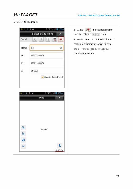
C. Select from graph.
1) Click " "Select stake point
on Map. Click " ", the
software can extract the coordinate of
stake point library automatically in
the positive sequence or negative
sequence for stake.

78
2) Click "OK" to start staking-out Hi-Survey
Start staking-out
Stake interface
(indicate position of target point)
Backward: Southward
Towards the Right: Eastward
Delta H: Altitude difference between
stake coordinate and actual position
Name: Name of stake point
σ: Relative precision
HD: Horizontal Distance

79
V90 Plus GNSS RTK System Getting Started
2. Line staking
1. Stake line from line library.
1. Click "Survey"->"Stake
Line"->Click" " to enter into the
stake line interface;
Click "Survey"->"Stake Line"

80
Hi-Survey
2. Click " "-> Click "Add"

81
V90 Plus GNSS RTK System Getting Started
There are 2 methods to define the
straight line (select one according to
situation),
A. "2Points to define the line"
B. "One point + Azimuth angle"
1.Tick "2Points" to define the
straight line;
"2Points to define the straight line"
need two elements of "Start Point"
and "End Point".(Adding method
shall be in conformity with the
method to add the stake coordinate
point in the "Stake Point").
2. Define straight line: There are 2 methods to define the straight line, See as below shows.
A. "2Points to define the line"
1) Select "2Points"->Input "Line Name" ->Select "Start Point" and "End Point" ->Click "OK"

82
Hi-Survey
2.Select "Start Point" and "End
Point" and click "OK"
1.The added straight line can be
viewed in the interface.
2) At the moment, the straight line is added successfully, which also can be edited and deleted, etc.

83
V90 Plus GNSS RTK System Getting Started
B. "One point + Azimuth angle"
1) Click "Add"->line->"Point + Azi"
2. Selected line can be edited and
deleted
1.Click "Add"->line

84
Hi-Survey
2) Select "Start point"->Input "Azi"->Click "Length" to input length of stake line->Click "OK" to
complete the addition of straight line;
1.Input the name of straight line and
add coordinate and azimuth angle of
"Start Point".
2. Tick "Point + Azi"

85
V90 Plus GNSS RTK System Getting Started
2. When extract the coordinate of one
point from the point library, input
azimuth angle (Azi) of straight line
and start station. Length refers to
length of stake straight line.
3. If added successfully, the added
straight line can be displayed.

86
Hi-Survey
1.Stake Interface: Including stake
direction.
3. Start to stake after adding the stake straight line successfully.
(1) Click " "->click "Milestone" to input milestone of point to be staked->click "OK" to enter
into the stake interface.
Cautions: Where the milestone and offset can be accumulated automatically according to the
increment.
2.Stake direction: Prompt direction of target location. Station of current stake: Refers to current
milestone of stake

87
V90 Plus GNSS RTK System Getting Started
1.Under "Project" of the main
interface>Data Transfer;
2.Select Stake Point->Import;
(2) Click " " again to enter into next point station in which station and offset can be accumulated
automatically based on increment.
3. Dxf file staking
1. Importing Dxf file as below shows.

3.Select "Dxf" file to be imported ->
click "OK"
4. Click "Blank" part->select import
format, such as (Name,N,E,Z, etc.),
and click "OK" to complete the
import.
88
Hi-Survey

Data achievement export supports the following format: *.txt, *.CSV, *.dxf, (shp File)*.shp and
(Excel File)*.csv.
The export procedures are as follows.
3.4 Data Export
1.Click" Data Transfer"
2.Select "Export" and Input name of
File->Select Export Format->Select
Saving Path
89
V90 Plus GNSS RTK System Getting Started

4. Select file format (take *.dxf for
example) ->click "OK" to complete
data export.
Export format of file
includes(8kinds):
User-defined(*.txt),
User-defined(*.CSV),
DxfFile(*.dxf),
ShpFile(*.shp),
Excel File(*.CSV),
South cass7.0(*.dat),
Scsg2000(*.dat),
PREGEO(*.dat).
90
Hi-Survey

Project is auto restored in Hi-Survey. External SD card is used for important data backup (Including:
Raw data, project file, coordinate system or encryption QR code file).
There are two kinds of backup, one is when users is setting project info he can click the auto-backup
in advance;Another is when users is deleting project file and choose "Backup" in the delete
massage box.
1. Auto-backup function
(1)Project Info->Recov->Click" Auto backup"
3.5 Auto-backup function in Hi-Survey
1.Choose "Project Info"
91
V90 Plus GNSS RTK System Getting Started

2. Select "Recov"
3. Open "Auto backup"
Notice:The path of backup file:external SD card /ZHD-Bak/Project/Road.
92
Hi-Survey

2. Backup before delete
Backup before delete means users backup project file into external SD card before delete project file
.The path of backup file:external SD card /ZHD-Bak/Project/Road.
(1) Choose delete project file and long press it in "Project info"
1.Choose delete project file and long
press it in "Project info"
2. Select "Backup" in delete message
prompt box
93
V90 Plus GNSS RTK System Getting Started

3. Data Recovery
1.Click "Recov" in "Project Info"
2.Long press to choose backup file ,
" " represent all selected
After selected file, Click " Start
Recovery "
94
Hi-Survey

4. Backup/ Recovery path: external SD card /ZHD-Bak/Project/Road.
View backup file:File Manager->SD card->ZHD-Bak->Project->Road
File Manager->SD
card->ZHD-Bak->Project->Road
Notice:
1. External SD card is necessary before users backup project file.
2. All the backup operations are over version 1.0.2.
95
V90 Plus GNSS RTK System Getting Started

Simplified Operation of SurvCE
Simplified Operation of SurvCE
CCCC HHHH AAAA PPPP TTTT EEEE RRRR
4
96

Select "Select New/Existing Job" to
jump for selecting to open existing
project or newly established project.
Input Project Name
Then Click " ".
4.Simplified Operation of SurvCE1. Open "SurvCE" software
2. After project establishment, enter into "Setting" in the coordinate system. There are two ways:
A. Import existing coordinate system.
B. User-defined coordinate system.
97
V90 Plus GNSS RTK System Getting Started

A. Import existing coordinate system.
Click "Add Predefined"->Select coordinate system->Click" " to complete the addition of
coordinate system.
B. User-defined coordinate system
Coordinate system can also be manually modified.
Click "Add Predefined"
Click " " to complete the
addition of coordinate system
98
Simplified Operation of SurvCE

3. Connect instrument and set Base
The connection between controller and receiver is established by Bluetooth.
1) Click "Equip"->GPS Base
Interface of GPS Base setting:
Manufacturer: Select "Hi-Target"
Model (optional): Select
corresponding model
Model drop-down box for selection
99
V90 Plus GNSS RTK System Getting Started

2) Click "Comms"->Type: Bluetooth->click ->Find Device-(Search for Bluetooth device)
Click "Comms" -> Type: Bluetooth
Click" "->Find Device
(Search for bluetooth device)
100
Simplified Operation of SurvCE

3) Select instrument as "Base">Set Device PIN>click " ", at the moment, the Bluetooth
connection is successful.
4) Click "RTK" to configure Base
Select S/N of instrument as "Base",
click" "
Set Device PIN,Input "1234"
Click " " to complete the
connection
(Take built-in UHF for example)
->set difference scheme-> ,
configure power, transceiver channel
and air Baud rate
101
V90 Plus GNSS RTK System Getting Started

5) For obtaining coordinates of Base
Click" " enter into transceiver
setting
click" " to complete
click "Read From GPS"->smooth
obtaining ->click "Yes"
102
Simplified Operation of SurvCE

4. Set Rover
The procedures to set rover are similar as to base.
Note:
1. When receiver works in UHF mode, settings should be exactly same as the Base
2. When receiving the correction from Network,the parameters of VRS should be input to the rover
correctly.
Average setting
"By Number" or "By Time in min"
for optional
103
V90 Plus GNSS RTK System Getting Started

Trouble Shooting■ Reset operation
■ Restore the iHand20 to factory settings
■ USB virtual serial port driver installation
■ Firmware update
■ Modify PCC radio with GM-xxPx management software
Trouble Shooting
CCCC HHHH AAAA PPPP TTTT EEEE RRRR
5
104

5.Trouble Shooting
5.1 Reset operation
When the Bluetooth is not connected, satellite searching fails and network connection fails, the
operation can be conducted in case that instrument restarting does not work.
Reset receiver : In power on status ,long press power button(3s≤long press time≤6s) when voice
prompts first "dingdong" ,release power button to power off ,and press 1s to power on.
Reset mainboard : In power on mode, long press power button for more than 6s, when voice
prompts the second "dingdong" then release power button . (Purpose: Restore the mainboard to the
initial mode.)
5.2 Restore the iHand20 to factory settings
These steps can help to solve the situation when the instrument appears unresponsive or crash.
Procedures :
1. Enter recovery mode
(1)Shutdown the controller, long press both “ and ” keys . Then the controller will be
into recovery mode.
105
V90 Plus GNSS RTK System Getting Started

2. Wipe user data:
Press “ & ”keys to move the cursor and highlight “wipe data/factory reset”, and
then press to enter the following interface.
(2) Press to enter the following interface.
3. Move the cursor and highlight” yes—delete all user data” ,than press to confirm and delete
the user data.
4. Move the cursor and highlight” wipe cache partition”, press to confirm and wipe cache
partition.
106
Trouble Shooting

5.3 USB virtual serial port driver installation
Installation steps are as follows.
1. Confirm to open the virtual serial port driver function, users can view and check these settings
by iHand20.
2. Connect receiver with PC by micro USB cable and install the driver. The driver file support
Windows 7 32 bit, Windows XP 32 bit, other system need to be tested.
3. After connected, It will prompt "Installing device driver software".
5. Highlight “reboot system now”, press to confirm and restart the phone.
107
V90 Plus GNSS RTK System Getting Started

4. Choose "Skip obtaining driver software from Windows update" and open "Computer
management"; In "Other devices" choose the "CDC Serial"
5. Right click "CDC Serial" and choose "Upgrade Driver Software" and select"linux_cdc_seial.inf
" then click next.
108
Trouble Shooting

6. If searched the effective software, the pop-up window will appear, and choose "Install this driver
software anyway".
7. Successfully updated information will show as below.
109
V90 Plus GNSS RTK System Getting Started

5.4 Firmware update
Receiver’s firmware updating steps are showed as below.
1. Power on V90 Plus GNSS receiver, connect receiver with PC by manufacture equipped USB
cable. Then open "My Computer" ," update "disk will display.
5.5 Modify PCC radio with GM-xxPx management software
For PCC radio, users can modify the channel parameters and communication protocol by GM-xxPx
management software.
Procedure shows as below
1. Connect GNSS receiver radio with GM-xxPx management software
Connect V90 Plus to computer then choose the correct COM port ->Open-> Connect;
2. Copy the firmware to "update" disk, remove it and disconnect USB cable, restart GNSS receiver.
3. Restart the process of upgrading will have corresponding voice prompts, if update failed please
contact the technician for help.
110
Trouble Shooting

2. Modify radio parameters
There are two ways to modify the radio parameters which including Bandwidth,Channels,Radio
Link and Protocol.
1) Manually modify
Choose radio->input "RX" and "RY"-> Apply->Program;
The other parameters can be modified in the corresponding selection box.
After modified the channel parameters, please restart the GNSS receiver.
2) Radio parameters can also be imported from a sheet file (*.ini) which contains all the
parameters and can be automatically applied.
111
V90 Plus GNSS RTK System Getting Started

(1) Click "Import"
(2) Choose file->Open (File format:*.ini)
112
Trouble Shooting

(3) Click" Program"
(4)Set parameters Ok!
Note:
1. When the parameters modification is OK, you can export it into parameter sheet (*.ini ) file then
import and apply it to other receivers.
2. Please restart the GNSS receiver after conducted.
113
V90 Plus GNSS RTK System Getting Started

Technical Parameters■ GNSS receiver
■ Communication
■ Controller
Technical Parameters
CCCC HHHH AAAA PPPP TTTT EEEE RRRR
6
114

6.Technical Parameters6.1 GNSS receiver
Satellite Signals Tracked Simultaneously
Receiver Precision
Simultaneous L1C/A, L2C, L2E, L5
Simultaneous L1C/A, L1P, L2C/A (GLONASS M only), L2P
Simultaneous L1 C/A, L5
Simultaneous L1 BOC, E5A, E5B, E5AltBOC(optional)
B1, B2
L1 C/A, L1 SAIF, L2C, L5
2.5mm+0.5ppm RMS
5mm+0.5ppm RMS
Typically <10s
Typically > 99.9%
1cm+1ppm RMS
2.5cm+1ppm RMS
Typically 10 minutes for base while 5 minutes for rover
Typically > 99.9%
8mm+1ppm RMS
15mm+1ppm RMS
8mm+0.5ppm RMS
15mm+0.5ppm RMS
Typically < 8seconds
220 Channels
GPS
GLONASS
SBAS
Galileo
BDS
QZSS
Static and Fast Static GNSS Surveying
Horizontal
Vertical
Initialization time
Initialization reliability
Post Processing Kinematic(PPK / Stop & Go) GNSS Surveying
Horizontal
Vertical
Initialization time
Initialization reliability
Real Time Kinematic (RTK) Surveying
Single Baseline
Horizontal
Vertical
Network RTK
Horizontal
Vertical
Initialization time
115
V90 Plus GNSS RTK System Getting Started

Hardware
153mm x 83mm (6.02inch x 3.27inch)
≤1.0kg without internal battery
-40℃to +65℃ (-40℉ to +149℉)
-40℃ to +75℃(-40℉ to +167℉)
100%, considering
IP67 dustproof, protected from temporary
immersion to depth of 1m (3.28ft).
Designed to survive a 3m(9.84ft) natural fall
onto concrete.
6V to 28V DC external power input
≤3.5W
12hours
8 hours
(UHF/GPRS/3G) 8-10 hours
1 x RS232 serial port
1 x DC power input (5-pin)
1x SIM Card slot
1x SD Card slot
Physical
Dimensions (W x H)
Weight
Operating temperature
Storage temperature
Humidity
Water/dustproof
Shock and vibration
Electrical
Power
Power consumption
Automatic switching between internal power and external power Rechargeable,
removable 7.4V, 5000mAh Lithium-ion battery in internal battery compartment
Internal Battery Life
Static
RTK base
RTK rover
I/O Interface
1 x Bluetooth, WIFI,NFC interface
1 x Radio Module
1 x WCDMA communication module
1 x standard mini USB2.0 port
Typically > 99.9%
25cm+1ppm RMS
50cm+1ppm RMS
0.50m Horizontal, 0.85m Vertical
Initialization reliability
Code Differential GNSS Positioning
Horizontal
Vertical
SBAS
116
Technical Parameters

6.2 Communication
450~470MHz with 116 channels
0.5W, 1W, 2W adjustable
9.6Kbps, 19.2Kbps
3~5km typical, 8~10kmoptimal
403~473MHz
Network Communication
Fully integrated, fully sealed internal WCDMA, compatible with GPRS, GSM
WIFI frequency is 2.4G, supports 802.11b/g/n protocol
Network RTK (via CORS) range20-50km
HI-TARGET Internal UHF Radio(Standard)
Frequency
Transmitting power
Transmitting speed
Working range
Pacific Crest XDL Micro Internal UHF Radio
Frequency
System Configuration
AM3352CotexA8 Platform
16GB Internal storage (Support up to 32GB
external SD card)
sCMRx、CMR、CMR+、RTCM 2.1、2.2、2.3
、3.0、3.1、3.2
GSOF
NMEA-0183 GSV, AVR, RMC, HDT, VGK,
VHD, ROT, GGK, GGA, GSA, ZDA, VTG,
GST, PJT, PJK, BPQ, GLL, GRS, GBS
1Hz positioning output, up to 20Hz
CPU
Storage
Record GNS and RINEX format simultaneously
Data Formats
Difference transmits format
Navigation outputs format(Binary)
Navigation outputs format(ASCII)
output frequency
1x built-in lithium battery interface1 x TNC antenna connector
Tilt Survey System
Electronic Bubble
117
V90 Plus GNSS RTK System Getting Started

0.5W, 2W adjustable
Up to 19.2Kbps
3~5km typical, 8~10km optimal
460MHz with 116 channels
5W, 10W, 20W, 30W adjustable
Up to 19.2Kbps
8~10km typical, 15~20km optimal
390~430MHz or 430~470MHz
4W to 35W adjustable
Up to 19.2Kbps
8~10km typical, 15~20km optimal
Transmitting power
Transmitting speed
Support most of radio communication protocol
Working range
HI-TARGET External UHF Radio (Standard)
Frequency
Transmitting power
Transmitting speed
Working range
Pacific Crest ADL Vantage Pro External UHF Radio
Frequency
Transmitting power
Transmitting speed
Support most of radio communication protocol
Working range
6.3 Controller
118
Technical Parameters

119
V90 Plus GNSS RTK System Getting Started

120
Technical Parameters

Socket and Main Accessories■ Preface
■ Difference antenna
■ Controller
V90 Plus GNSS RTK System Getting Started
CCCC HHHH AAAA PPPP TTTT EEEE RRRR
7
121

7.Socket and Main Accessories7.1 Preface
7.2 Difference antenna
The chapter will introduce the appearance and application of main interface of receiver and
accessories. The following equipment does not represent all users purchased V90 Plus. According to
different configurations, the specific configuration shall be subject to the delivery order upon
purchasing.
UHF base mode and UHF rover mode shall use difference antenna. The difference antenna of UHF
base mode is used to transmit UHF difference signal. The difference antenna of UHF rover mode is
used to receive UHF difference signal. 3G mode shall use 3G short antenna as right.
Difference antenna installation :
Grasp the fixed nut in bottom of different antenna with hand to install clockwise. On the contrary,
dismantle difference antenna anticlockwise.
Warning: when installing difference antenna, it shall rotate the fixed nut in bottom of
difference antenna with hand rather that grasping the upper side of difference antenna, or it will
break off the difference antenna.
122
Socket and Main Accessories

Data Cable
DDTHPB External Radio
Five-pin plug: connect Five-pin socket of receiver
Serial interface: it is used to connect with computer serial port, update receiver firmware, set the
receiver, manage static data and set the radio.
DDTHPB external radio is a type of radio improving the performance of relay radio UH-3000.
DDTHPB radio has all functions of URS relay radio. Compared to other radios, it is also functional
in power transposition protection. Even though the external power is connected wrongly, DDTHPB
radio will not be burn out.
Warning:
1. when connecting various plugs of receiver, it shall align the red point in line joint at the red point
in receiver socket, or it will damage the receiver socket and plugs of various lines.
2. When plug out the plug, directly grasp the sliding collar and pull out the plug with effort. It shall
not rotate the plug.
3. After using the cable, it shall place the cable in the place difficult for extrusion, in order to prevent
damaging the plug. When installing the difference antenna, it shall rotate the fixed nut in bottom of
difference antenna with hand, rather than grasping the upper side to rotate, or the difference antenna
will be in bad contact and influence the operating range.
Five-pin plug
Series interface
123
V90 Plus GNSS RTK System Getting Started

DDTHPB radio interface:
As for the specific operations of DDTHPB external radio, please refer to its manual.
1 2 3
56789
410
1. Field intensity/power voltage indicator D1
2. Dibit nixie tube indicator D2 3. Send-receive indicator light D3
4. Power/warning indicator D4 5. Key K4 (power on-off key)
6. Key K4 (channel increasing key) 7. Key K3 (channel decreasing key)
8. Key K2 (electric quantity checking key)
9. Key K1 (power toggle key) 10. Power indicator light D5
1. Base host to radio cable interface
2. External power interface
3. Transmitting antenna interface
31
2
124
Socket and Main Accessories

Annexed Table 1 Defaulted Frequency Table upon DeliveryThe user may change defaulted frequency of 16 channels of the radio.
Table 1 Defaulted frequency table of 16 channels in radio
Channel
0
1
2
3
4
5
6
7
Frequency(MHZ)
466.825
463.125
464.125
465.125
466.125
463.625
464.625
465.625
Channel
8
9
A
B
C
D
E
F
Frequency(MHZ)
466.625
463.325
464.325
465.325
466.325
463.825
464.825
465.825
125
V90 Plus GNSS RTK System Getting Started