v8 kdot boxes presentation - cpb-us-e1.wpmucdn.com · aashto std. spec. 17th ed. 2002 aashto lrfd...
TRANSCRIPT

10/4/2017
1
© 2015 HDR, Inc., all rights reserved.
© 2015 HDR, Inc., all rights reserved.
LFD Rating of Composite Steel Tub Girders in
AASHTOWare BrR
Kevin Gribble, P.E., and Brian Zeiger, P.E.
KDOT STEEL LOAD RATING PROJECT
10/4/2017
2
Deliverable – AASHTOWare Model of Every Bridge or Unit – 46 total steel units of varying superstructure type and complexity
To be used in KDOT’s K-TRIPS: Kansas Truck Routing and Intelligent Permitting
System
KDOT STEEL LOAD RATING PROJECT
o Curved I-Girder Bridges (SFGC, SFCC)
• Heavy Skew Curved Multi-Girder Systems with Hinges, AASHTOWare 3D FEM
• Curved Two-Girder Systems with Hinges, AASHTOWare 3D FEM
o Straight and Curved Steel Tub Girder Bridges (SBCC)
• Equivalent I-Girder Method in AASHTOWare (presented today)
KDOT STEEL LOAD RATING PROJECT
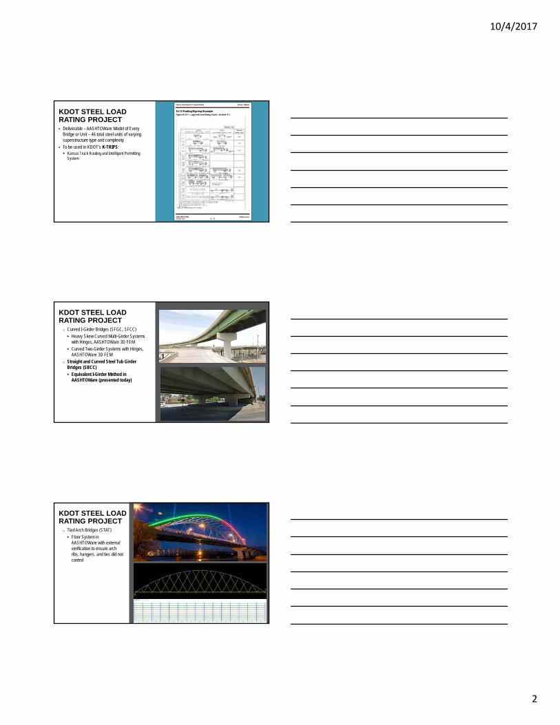
o Tied Arch Bridges (STAT)
• Floor System in AASHTOWare with external verification to ensure arch ribs, hangers, and ties did not control
KDOT STEEL LOAD RATING PROJECT
10/4/2017
3
o K-Frame Grasshopper Bridges (SRFC, WRFC)• Simplified AASHTOWare Spring Constant
Method with external verification to ensure frame legs did not control
• Once legs shown not to control, simplified AASHTOWare method was used for girders inside AASHTOWare BrR
KDOT STEEL LOAD RATING PROJECT
Leg
Girder
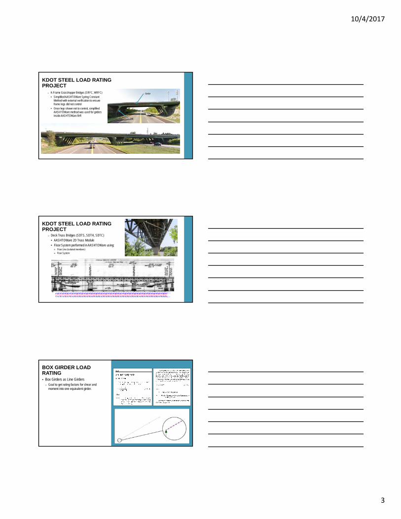
o Deck Truss Bridges (SDTS, SDTH, SDTC)
• AASHTOWare 2D Truss Module
• Floor System performed in AASHTOWare using:» Floor Line (isolated members)
» Floor System
KDOT STEEL LOAD RATING PROJECT
Box Girders as Line Girders o Goal to get rating factors for shear and
moment into one equivalent girder.
BOX GIRDER LOAD RATING
10/4/2017
4
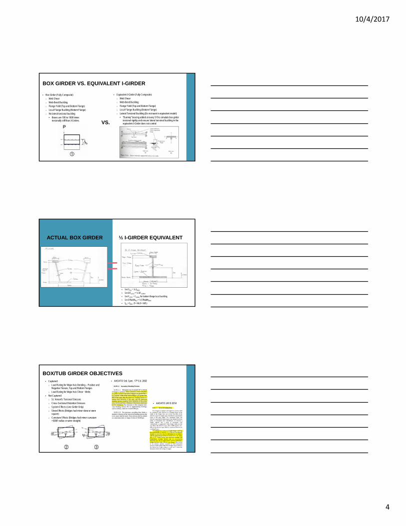
Box Girder (Fully Composite)
o Web Shearo Web-Bend Buckling
o Flange Yield (Top and Bottom Flange)o Local Flange Buckling (Bottom Flange)
o No lateral torsional buckling
• Boxes are 100 to 1000 times torsionally stiff than I-Girders.
BOX GIRDER VS. EQUIVALENT I-GIRDER
Equivalent I-Girder (Fully Composite)
o Web Shearo Web-Bend Buckling
o Flange Yield (Top and Bottom Flange)o Local Flange Buckling (Bottom Flange)
o Lateral Torsional Buckling (Do not want in equivalent model)
• “Dummy” bracing added at every 5 ft to simulate box girder torsional rigidity and ensure lateral torsional buckling in the equivalent I-Girder does not controlVS.
ACTUAL BOX GIRDER ½ I-GIRDER EQUIVALENT
Set SEQ = ½ SBOX
Set DFLLEQ = ½ DFLLBOX
Set FcrEQ = FcrBOX for bottom flange local buckling
Set EffwidthEQ = ½ EffwidthBOX
fEQ = fBOX (f = Mc/I = M/S)
Captured:
o Load Rating for Major Axis Bending – Positive and Negative Flexure, Top and Bottom Flanges
o Load Rating for Major Axis Shear - Webs
Not Captured:o St. Venant’s Torsional Stresses
o Cross-Sectional Distortion Stresses o System Effects (Line Girder Only)
o Skew Effects (Bridges had minor skew or were square)
o Curvature Effects (Bridges had minor curvature >5000’ radius or were straight)
BOX/TUB GIRDER OBJECTIVES AASHTO Std. Spec. 17th Ed. 2002
AASHTO LRFD 2014

10/4/2017
5
EQUIVALENT STRESSES: BOX GIRDER VS. EQUIVALENT I-GIRDER ½ Girder Steel = ½ Steel Dead Load
½ Effective Deck Width = ½ Effective Deck Section for n and 3n ½ Tributary Deck Width = ½ Concrete Dead Load
½ Live Load Distribution Factor = ½ Live Load (Moment, Shear)
EQUIVALENT SHEAR FORCE: BOX GIRDER VS. EQUIVALENT I-GIRDER
With C factor included in calculation, ~2% error or less in most cases with d0 normalized over the difference in D of the web
AASHTO Std. Spec. 17th Ed. 2002
AASHTO Std. Spec. 17th Ed. 2002
LIVE LOAD DISTRIBUTION
Compute DF of actual box girder
10/4/2017
6
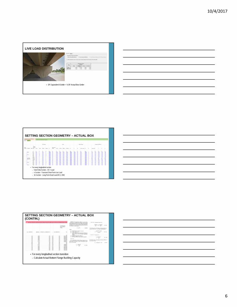
LIVE LOAD DISTRIBUTION
DF Equivalent I-Girder = ½ DF Actual Box Girder
SETTING SECTION GEOMETRY – ACTUAL BOX
For every longitudinal sectiono Steel Only Section – DC1 Load
o n Section – Transient Short-Term Live Loado 3n Section – Long-Term Dead Load (DC2, DW)
SETTING SECTION GEOMETRY – ACTUAL BOX (CONTIN.)
For every longitudinal section transition
o Calculate Actual Bottom Flange Buckling Capacity
10/4/2017
7
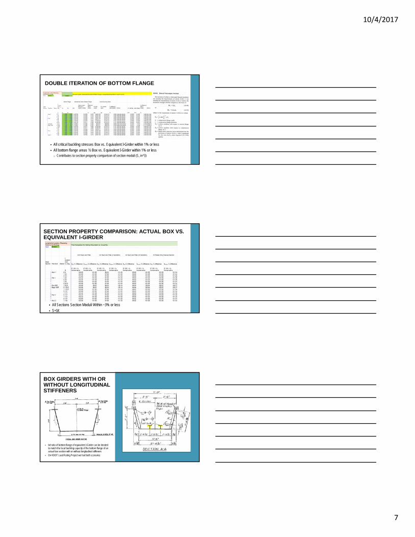
All critical buckling stresses Box vs. Equivalent I-Girder within 1% or less
All bottom flange areas ½ Box vs. Equivalent I-Girder within 1% or lesso Contributes to section property comparison of section moduli (S, in^3)
DOUBLE ITERATION OF BOTTOM FLANGE
All Sections Section Moduli Within ~3% or less
S=I/c
SECTION PROPERTY COMPARISON: ACTUAL BOX VS. EQUIVALENT I-GIRDER
BOX GIRDERS WITH OR WITHOUT LONGITUDINAL STIFFENERS
b/t ratio of bottom flange of equivalent I-Girder can be iterated to match the local buckling capacity of the bottom flange of an actual box section with or without longitudinal stiffeners
On KDOT Load Rating Project we had both scenarios
10/4/2017
8
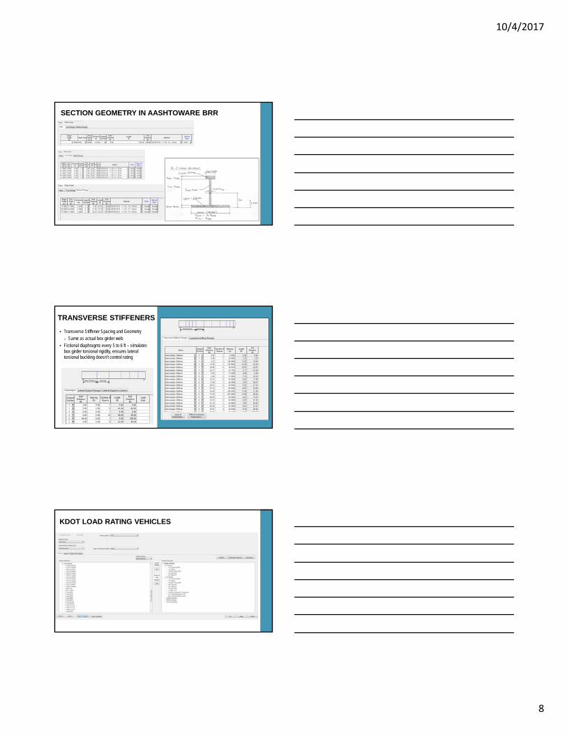
SECTION GEOMETRY IN AASHTOWARE BRR
Transverse Stiffener Spacing and Geometry
o Same as actual box girder web
Fictional diaphragms every 5 to 6 ft – simulates box girder torsional rigidity, ensures lateral torsional buckling doesn’t control rating
TRANSVERSE STIFFENERS
KDOT LOAD RATING VEHICLES
10/4/2017
9
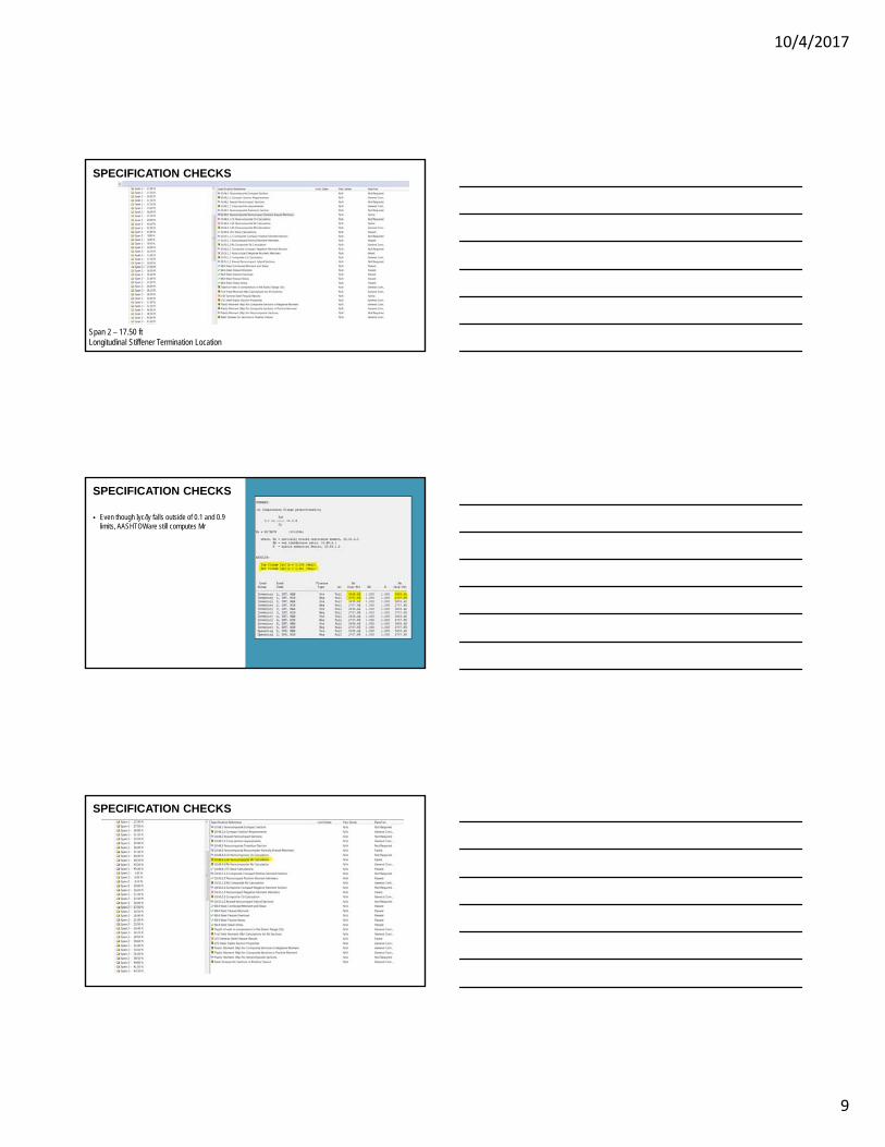
SPECIFICATION CHECKS
Span 2 – 17.50 ftLongitudinal Stiffener Termination Location
SPECIFICATION CHECKS
Even though Iyc/Iy falls outside of 0.1 and 0.9 limits, AASHTOWare still computes Mr
SPECIFICATION CHECKS
10/4/2017
10
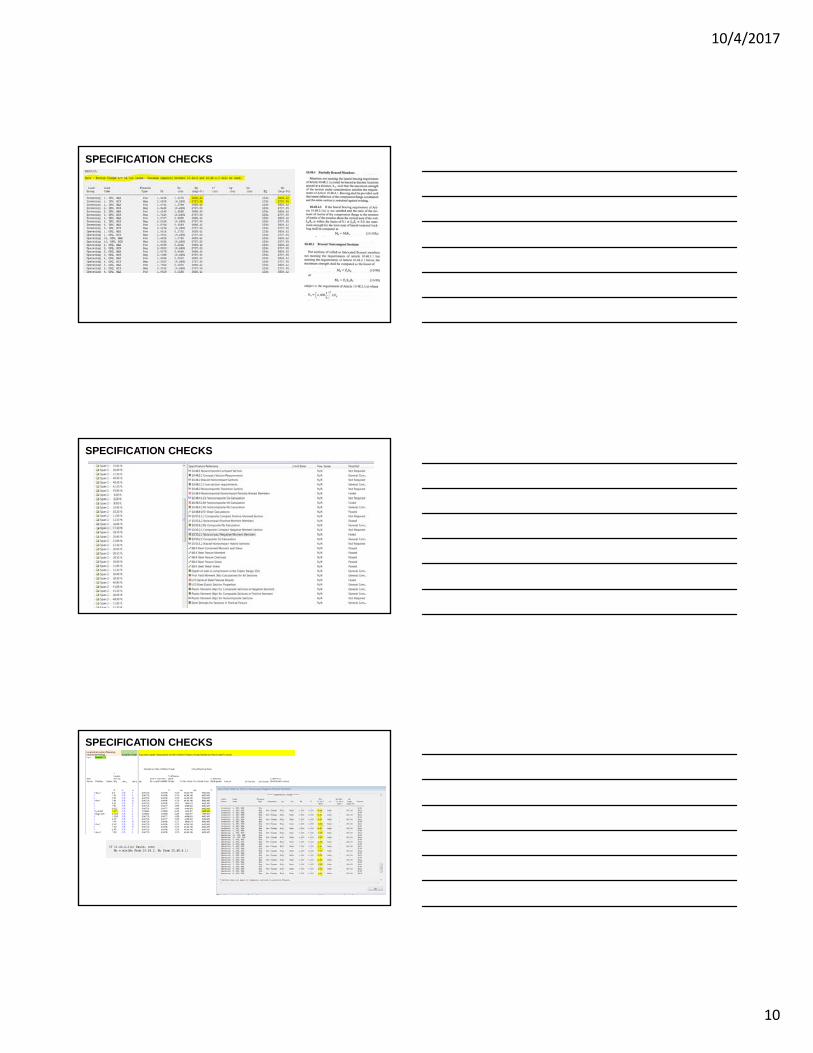
SPECIFICATION CHECKS
SPECIFICATION CHECKS
SPECIFICATION CHECKS
10/4/2017
11
SPECIFICATION CHECKS
SPECIFICATION CHECKS
The girder does not satisfy noncompact criteria for compressive strength so AASHTOWare takes the minimum of the partially braced compressive capacity or the local flange buckling capacity.
Since the partially braced capacity is Fy due to the fictional bracing input at every 5’, local flange buckling controls
Therefore, for the bottom flange, AASHTOWare checks capacity to Fy and Fcr only, mimicking the behavior of the actual box girder
Fcr = 4.86 ksi
S, negative moment = 691.73 in^3 Mu=Fcr x S
Mu=4.86 ksi x 691.73 in^3 x 1/12 in = 280 k-ft (verified)
FINAL BOX GIRDER RATING SUMMARY N.B. I-635 over E.B I-35
Results: o typically areas of high moment or areas with abrupt changes in capacities i.e. flange transitions or longitudinal stiffener
termination locations controlled the ratingo Shear controlled rating for areas of high shear, heavy axles on various trucks, panel length changes due to changes in
transverse stiffener spacing
10/4/2017
12
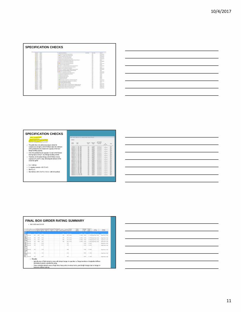
Modeling of K-Frame Grasshopper Bridges using simplified spring method with external verification
OTHER STEEL RATING METHODS
I-435 over I-70
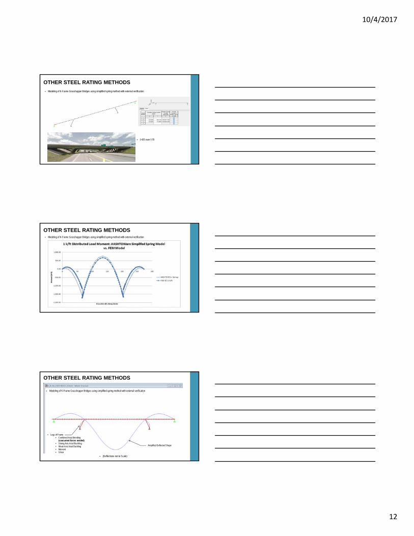
OTHER STEEL RATING METHODS Modeling of K-Frame Grasshopper Bridges using simplified spring method with external verification
OTHER STEEL RATING METHODS
(Deflections not to Scale)
• Legs of Frame• Combined Axial-Bending
(concurrent forces needed)• Strong Axis Axial Buckling• Weak Axis Axial Buckling• Moment• Shear
Modeling of K-Frame Grasshopper Bridges using simplified spring method with external verification
Amplified Deflected Shape

10/4/2017
13
OTHER STEEL RATING METHODS Modeling of K-Frame Grasshopper Bridges using simplified spring method with external verification
OTHER STEEL RATING METHODS Modeling of K-Frame Grasshopper Bridges using simplified spring method with external verification
OTHER STEEL RATING METHODS
VS.
AASHTOWare BrR STAAD FEM/Excel Post-Processing
Modeling of K-Frame Grasshopper Bridges using simplified spring method with external verification
10/4/2017
14
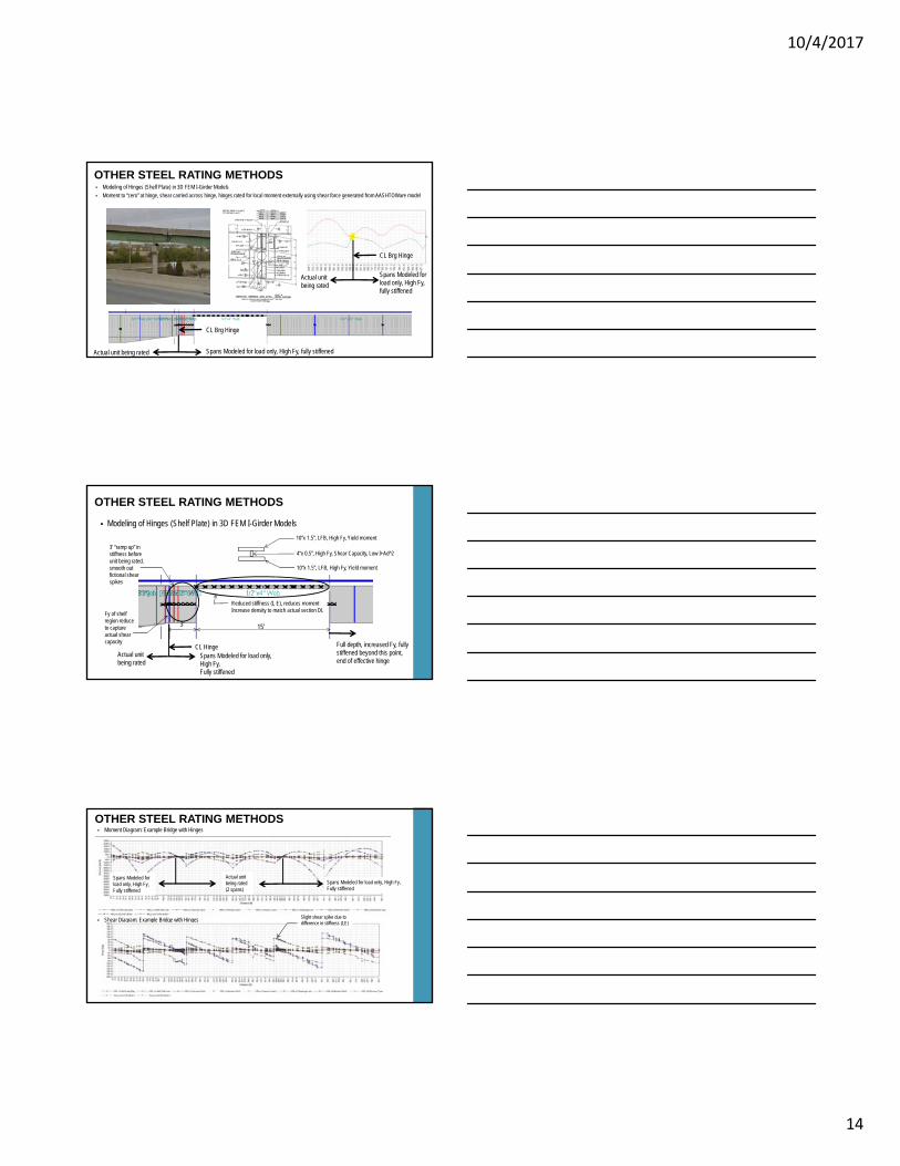
Modeling of Hinges (Shelf Plate) in 3D FEM I-Girder Models
Moment to “zero” at hinge, shear carried across hinge, hinges rated for local moment externally using shear force generated from AASHTOWare model
OTHER STEEL RATING METHODS
Spans Modeled for load only, High Fy, fully stiffened
CL Brg Hinge
Actual unit being rated
CL Brg Hinge
Spans Modeled for load only, High Fy, fully stiffened
Actual unit being rated
Modeling of Hinges (Shelf Plate) in 3D FEM I-Girder Models
OTHER STEEL RATING METHODS
15’3’
CL Hinge
10”x 1.5”, LFB, High Fy, Yield moment
10”x 1.5”, LFB, High Fy, Yield moment
4”x 0.5”, High Fy, Shear Capacity, Low I+Ad^2
Spans Modeled for load only, High Fy, Fully stiffened
Actual unit being rated
Reduced stiffness (I, E), reduces momentIncrease density to match actual section DL
3’ “ramp up” in stiffness before unit being rated, smooth out fictional shear spikes
Fy of shelf region reduce to capture actual shear capacity Full depth, increased Fy, fully
stiffened beyond this point, end of effective hinge
OTHER STEEL RATING METHODS Moment Diagram: Example Bridge with Hinges
Shear Diagram: Example Bridge with Hinges
Spans Modeled for load only, High Fy, Fully stiffened
Actual unit being rated(2 spans)
Spans Modeled for load only, High Fy, Fully stiffened
Slight shear spike due to difference in stiffness (I,E)
10/4/2017
15
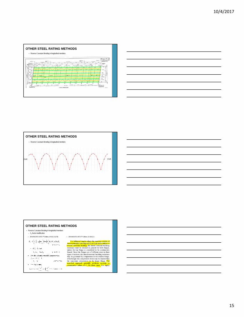
OTHER STEEL RATING METHODS Reverse Curvature Bending in longitudinal members
OTHER STEEL RATING METHODS
Reverse Curvature Bending in longitudinal members
0 k-ft 0 k-ft
Reverse Curvature Bending in longitudinal memberso Cb factor modification
OTHER STEEL RATING METHODS
2014 AASHTO LRFD 7th Edition, C6.10.8.2.3 2014 AASHTO LRFD 7th Edition, 6.10.8.2.3 (LTB)
10/4/2017
16
Reverse Curvature Bending in longitudinal memberso Cb factor modification
OTHER STEEL RATING METHODS
1961 AASHO
AISC Steel Manual, 14th Edition
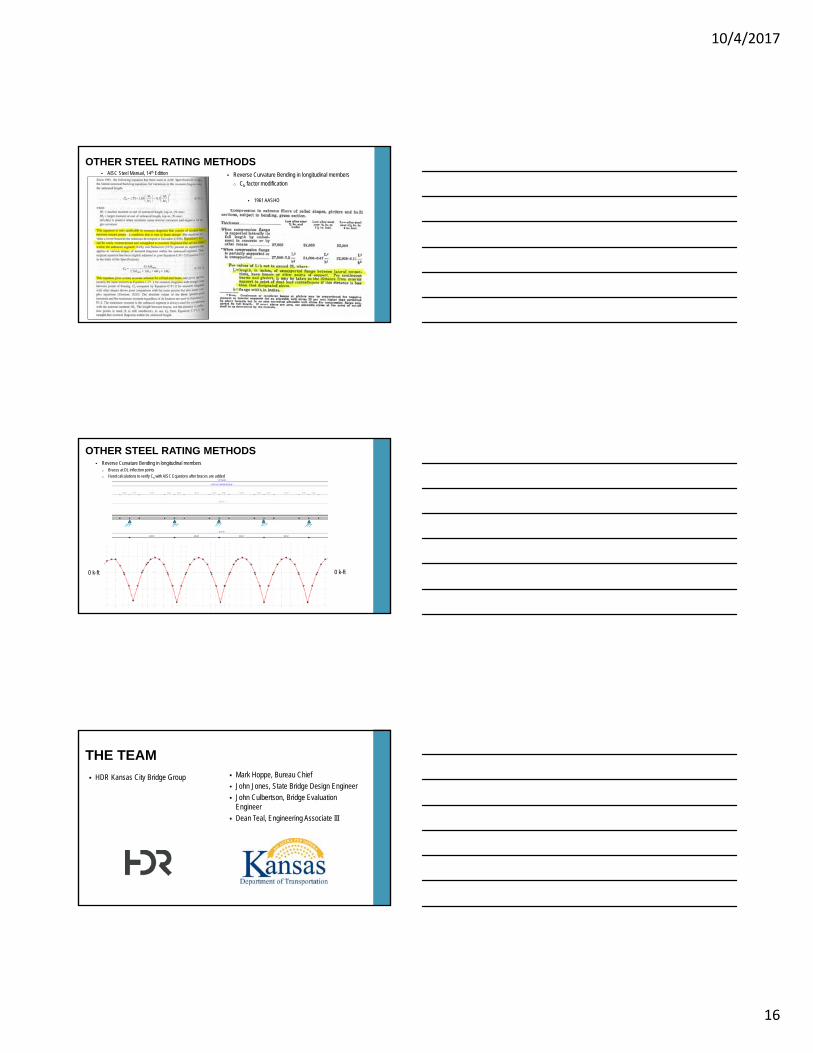
OTHER STEEL RATING METHODS Reverse Curvature Bending in longitudinal members
o Braces at DL inflection points
o Hand calculations to verify Cb with AISC Equations after braces are added
0 k-ft0 k-ft
Mark Hoppe, Bureau Chief
John Jones, State Bridge Design Engineer
John Culbertson, Bridge Evaluation Engineer
Dean Teal, Engineering Associate III
THE TEAM
HDR Kansas City Bridge Group
10/4/2017
17
QUESTIONS?
© 2015 HDR, Inc., all rights reserved.