v7 3370 operations manual - ahern australia › wp-content › themes › xtreme...self-propelled...
TRANSCRIPT
OPERATION
MANUALPart Num ber 1
201 (Rev )
Ver sion
Se rial Num bers:
and after
Die selGas o lineLPGBi-En ergy 24V DC
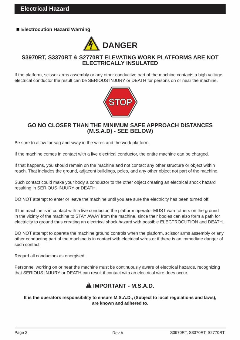
Electrocution Hazard Warning
DANGERS3970RT, S3370RT & S2770RT ELEVATING WORK PLATFORMS ARE NOT
ELECTRICALLY INSULATED
If the platform, scissor arms assembly or any other conductive part of the machine contacts a high voltage electrical conductor the result can be SERIOUS INJURY or DEATH for persons on or near the machine.
GO NO CLOSER THAN THE MINIMUM SAFE APPROACH DISTANCES(M.S.A.D) - SEE BELOW)
Be sure to allow for sag and sway in the wires and the work platform.
If the machine comes in contact with a live electrical conductor, the entire machine can be charged.
If that happens, you should remain on the machine and not contact any other structure or object within reach. That includes the ground, adjacent buildings, poles, and any other object not part of the machine.
Such contact could make your body a conductor to the other object creating an electrical shock hazard resulting in SERIOUS INJURY or DEATH.
DO NOT attempt to enter or leave the machine until you are sure the electricity has been turned off.
If the machine is in contact with a live conductor, the platform operator MUST warn others on the ground in the vicinty of the machine to STAY AWAY from the machine, since their bodies can also form a path for electricity to ground thus creating an electrical shock hazard with possible ELECTROCUTION and DEATH.
DO NOT attempt to operate the machine ground controls when the platform, scissor arms assembly or any other conducting part of the machine is in contact with electrical wires or if there is an immediate danger of such contact.
Regard all conductors as energised.
Personnel working on or near the machine must be continuously aware of electrical hazards, recognizing that SERIOUS INJURY or DEATH can result if contact with an electrical wire does occur.
IMPORTANT - M.S.A.D.
It is the operators responsibility to ensure M.S.A.D., (Subject to local regulations and laws),are known and adhered to.
Page 2 Rev A S3970RT, S3370RT, S2770RT
Electrical Hazard
The most important chapter in this manual is the safety chapter - Chapter 1. Take time now to study it closely.
The information in chapter 1 might save your life, prevent serious injury or damage of property to the S2770RT / S3370RT / S3970RT.
This introduction also contains important information concerning the responsibilities of the owner of the machine.
Standard S3970RT / S3370RT / S2770RT Version III
The standard S3970RT/S3370RT/S2770RT includes the following features:
• Fully proportional one (1) handed joy stick control
• Reliable diesel engine• Large 1200mm multi position extension deck• 30% 35% gradeability• 4 wheel drive• Hour Meter• Temperature & ammeter gauges• Easy access side trays for engine & hydraulics• Lockable hinged covers• Independently operated hydraulic stabilisers with
auto level• Swinging gate• Independent articulating rear axles• Forklift pockets• Lifting lugs and tie down rings• Flashing light
Options
The following options are available for the S3970RT / S3370RT / S2770RT:
• No stabilisers• Non-marking tyres• 110/240V power to platform• RCD/ELCB Outlet• Alternative power options Gasoline engine LPG engine Combination LPG/Gasoline engine Bi-Energy 24V DC / Diesel egnine
Operation Manual
This manual provides information for sale and proper operation of the aerial platform. Read and understand the information in this Operator’s manual before operating this machine on a job site.
Additional copies of this manual may be ordered from Snorkel. Supply the model and manual part number from the front cover to assure the correct manual will be supplied.
All information in this manual is based on the latest product information at the time of publication. Snorkel reserves the right to make product changes at any time without obligation.
Photographs
Photographs are taken to represent the machine and its component parts as clearly as possible. However, there may be minor differences between the photographs and your machine. This represents individual customer preferences and Snorkels on going commitment to product development.
Safety Alerts
A safety alert symbol is used throughout this manual to indicate danger, warning and caution instructions. Follow these instructions to reduce the likelihood of personal injury, property damage or damage to the machine.
The terms danger, warning and caution indicate varying degrees of personal injury or property dam-age that can result if the instruction is not followed.
DANGERDenotes an Imminently hazardous situation which if not avoided, will result in serious injury or death.
WARNINGDenotes a potentially hazardous situation which if not avoided, could result in serious injury or death.
CAUTIONDenotes a potentially hazardous situation which if not avoided, may result in minor or moderate injury. It may also be used to alert against unsafe prac-tices or action which may result in damage to the machine.
S3970RT, S3370RT, S2770RTRev APage 3
Introduction
The Operators Manual provides a daily inspection procedure that will help you keep your S3970RT / S3370RT / S2770RT in good operating condition.
Do not perform other maintenance unless you are a trained mechanic, qualifi ed to work on the S3970RT / S3370RT / S2770RT. Call qualifi ed maintenance per-sonnel if you fi nd problems or malfunctions.
Do not modify this machine without written approv-al from the Engineering Department of Snorkel. Modifi cation may void the warranty, adversely affect stability, or affect the operational characteristics of the S3970RT / S3370RT / S2770RT.
Responsibilities of parties
It is imperative that all owners and users of the S3970RT / S3370RT / S2770RT read, understand, and conform to all applicable regulations. Ultimate compliance to OSHA regulations is the responsibility of the user and their employer.
IMPORTANT
It is imperative that all owners and users of the S3970RT / S3370RT / S2770RT read, understand and conform to all applicable regulations. Ultimate compliance to OSHA regulations is the responsibility of the user and their employer.
IMPORTANT
ANSI Standard A92.6 clearly identifi es require-ments of all parties who might be involved with Self-Propelled Elevating Work Platforms.Australian / NZ Standard 2550-10 also identifi es the requirements of all parties who might be in-volved with Boom-Supported Elevated Work Platforms.
NoteIt is the responsibility of the owner to ensure that the person operating the machine is provided with all the relevant information relating to standards and codes of practice applicable in their region.
In Summary
• Only trained and authorised operators should be permitted to operate the equipment.
• All manufacturers operating instructions and safety rules and all employers safety rules and all OSHA and other government safety rules should be strictly adhered to.
IMPORTANT
Denotes important informations pertaining to settings, capacities, conditions, which could, if ignored lead to machine damage or future hazardous situations. It is also used to alert the reader to pay careful attention to a particular passage of text in the manual.
Notes:Notes are used to provide special information or helpful hints to assist in aerial platform operation, but do not indicate a hazardous situation.
Operation
The S3970RT / S3370RT / S2770RT aerial platform has built in safety features and has been factory test-ed for compliance with Snorkel specifi cations and industry standards. However, any personnel lifting device can be potentially dangerous in the hands of untrained or careless operators.
Training is vitally important and must be performed under the direction of a qualifi ed person. You must display profi ciency in knowledge and actual operation of the machine before using it on a job site.
Before operation of the machine you must read and understand the operating instructions in this manual as well as the decals, warnings and instructions on the machine itself.
Before operating the machine you must be authorised by the person in charge to do so and the operation ofthe machine must be within the scope of the machine specifi cations.
WARNING
The potential for an accident increases when the aerial platform is operated by personnel who are not trained and authorised. Death or serious inju-ry can result from such accidents.Read and understand the information in this manual and the placards and decals on the machine before operating the machine on the job site. Maintenance
Every Person who maintains, inspects, tests or re-pairs these machines, and every person supervising any of these functions, must be properly trained and qualifi ed to do so.
Page 4 Rev A S3970RT, S3370RT, S2770RT
Introduction

• Repairs and adjustments should be made only by qualifi ed and trained maintenance personnel.
• No modifi cation should be made to the equip-ment without prior written consent of the Snorkel Engineering Department.
• Make a pre-start inspection of the S3970RT / S3370RT / S2770RT at the beginning of each shift. A malfunctioning machine must not be used.
• Make an inspection of the workplace to locate possible hazards before operating the S3970RT / S3370RT / S2770RT.
Product Warranty
For full terms of your warranty policy please refer to the Repair Parts Manual, or check with your Snorkel distributor, or check the Snorkel website.
Additional Information
For additional information, contact your local dealer or Snorkel at:
Snorkel New ZealandPO Box 1041Levin 5510New Zealand
S3970RT, S3370RT, S2770RTRev APage 5
Introduction

Page 6 Rev A S3970RT, S3370RT, S2770RT

S3970RT, S3370RT, S2770RTRev APage 7
Electrical Hazard
Electrical Hazard Warning . . . . . . . . . . . . . . . . . . . . . 2
Introduction
Standard S3970RT/S3370RT/S2770RT Version III .3Options . . . . . . . . . . . . . . . . . . . . . . . . . . . . . . . . . . . 3Operation Manual . . . . . . . . . . . . . . . . . . . . . . . . . . . 3Photographs . . . . . . . . . . . . . . . . . . . . . . . . . . . . . . . 3Safety Alerts . . . . . . . . . . . . . . . . . . . . . . . . . . . . . . . 3Operation . . . . . . . . . . . . . . . . . . . . . . . . . . . . . . . . . 4Maintenance . . . . . . . . . . . . . . . . . . . . . . . . . . . . . . . 4Responsibilities of Parties . . . . . . . . . . . . . . . . . . . . . . 4Product Warranty . . . . . . . . . . . . . . . . . . . . . . . . . . . 5Additional Information . . . . . . . . . . . . . . . . . . . . . . . . 5
1. Safety
Safe Operation . . . . . . . . . . . . . . . . . . . . . . . . . . . . 1-1Electrocution Hazards . . . . . . . . . . . . . . . . . . . . . . 1-1Pre-start Inspection . . . . . . . . . . . . . . . . . . . . . . . . 1-1Workplace Inspection and Practices . . . . . . . . . . . 1-1Operation . . . . . . . . . . . . . . . . . . . . . . . . . . . . . . . 1-2Tipover and Falling Hazards . . . . . . . . . . . . . . . . . 1-2General Safety Precautions . . . . . . . . . . . . . . . . . . 1-3Hydraulic System Precautions . . . . . . . . . . . . . . . . 1-3Fire / Explosion Prevention . . . . . . . . . . . . . . . . . . 1-3Engine and Fuel Handling Precautions . . . . . . . . . 1-3Batteries . . . . . . . . . . . . . . . . . . . . . . . . . . . . . . . . . 1-4Safety Placards and Decals . . . . . . . . . . . . . . . . . 1-4Safety Placards and Decals Location . . . . . . . . . . 1-4
2. Safety Devices
Safety Device Information . . . . . . . . . . . . . . . . . . . 2-1Emergency Stop Switches . . . . . . . . . . . . . . . . . . 2-1 At platform control box . . . . . . . . . . . . . . . . . . . . 2-1 At ground control box . . . . . . . . . . . . . . . . . . . . . 2-1Alarms . . . . . . . . . . . . . . . . . . . . . . . . . . . . . . . . . . 2-1 Lowering . . . . . . . . . . . . . . . . . . . . . . . . . . . . . . . 2-1 High temperature . . . . . . . . . . . . . . . . . . . . . . . . . 2-2 Low oil pressure . . . . . . . . . . . . . . . . . . . . . . . . . 2-2 Alternator not charging . . . . . . . . . . . . . . . . . . . . 2-2 Drive (reverse) . . . . . . . . . . . . . . . . . . . . . . . . . . 2-2 Drive (forward) . . . . . . . . . . . . . . . . . . . . . . . . . . 2-2Load Sensing System . . . . . . . . . . . . . . . . . . . . . . 2-2 Level sensor . . . . . . . . . . . . . . . . . . . . . . . . . . . . 2-2Primary Fall Restraint System . . . . . . . . . . . . . . . 2-2Safety Prop . . . . . . . . . . . . . . . . . . . . . . . . . . . . . . 2-3Swinging Gate . . . . . . . . . . . . . . . . . . . . . . . . . . . 2-3Safety Control . . . . . . . . . . . . . . . . . . . . . . . . . . . . 2-3Bubble Level . . . . . . . . . . . . . . . . . . . . . . . . . . . . . 2-3Operator Horn . . . . . . . . . . . . . . . . . . . . . . . . . . . . 2-3Stabilisers (Option) . . . . . . . . . . . . . . . . . . . . . . . . 2-4Rough Terrain Scissor Interlock Tests . . . . . . . . . . 2-4 Enable switch . . . . . . . . . . . . . . . . . . . . . . . . . . . 2-4
RCD / ELCB AC Outlet (Option) . . . . . . . . . . . . . . 2-4Flashing Light . . . . . . . . . . . . . . . . . . . . . . . . . . . . 2-5Fall Restraint Lanyard Anchor Points (Option) . . . 2-5
3. Specifi cations
General Specifi cations Standard MachineS3970RT . . . . . . . . . . . . . . . . . . . . . . . . . . . . . . . . 3-1General Specifi cations Standard MachineS3370RT . . . . . . . . . . . . . . . . . . . . . . . . . . . . . . . . 3-2General Specifi cations Standard MachineS2770RT . . . . . . . . . . . . . . . . . . . . . . . . . . . . . . . . 3-3Engine Data . . . . . . . . . . . . . . . . . . . . . . . . . . . . . 3-4 DF752 (option) . . . . . . . . . . . . . . . . . . . . . . . . . . 3-4 D902 . . . . . . . . . . . . . . . . . . . . . . . . . . . . . . . . . . 3-4Machine Component Identifi cation . . . . . . . . . . . . 3-5
4. Gauges
EZCal LCD Display . . . . . . . . . . . . . . . . . . . . . . . . 4-1Water . . . . . . . . . . . . . . . . . . . . . . . . . . . . . . . . . . 4-1Alternator . . . . . . . . . . . . . . . . . . . . . . . . . . . . . . . 4-1Oil Pressure . . . . . . . . . . . . . . . . . . . . . . . . . . . . . 4-1Hours . . . . . . . . . . . . . . . . . . . . . . . . . . . . . . . . . . . 4-1 Work time . . . . . . . . . . . . . . . . . . . . . . . . . . . . . . 4-1 Total time . . . . . . . . . . . . . . . . . . . . . . . . . . . . . . . 4-1Engine Oil . . . . . . . . . . . . . . . . . . . . . . . . . . . . . . . 4-1Hydraulic Oil Level . . . . . . . . . . . . . . . . . . . . . . . . . 4-1 Bubble level . . . . . . . . . . . . . . . . . . . . . . . . . . . . 4-2
5. Automatic Shut-offs and Circuit Breakers
Automatic Shut-offs . . . . . . . . . . . . . . . . . . . . . . . . 5-1 Level sensor . . . . . . . . . . . . . . . . . . . . . . . . . . . . 5-1 Engine Temperature . . . . . . . . . . . . . . . . . . . . . . 5-1 Engine oil pressure . . . . . . . . . . . . . . . . . . . . . . . 5-1 Platform height vs drive speed . . . . . . . . . . . . . . 5-1 Dynamic brakes . . . . . . . . . . . . . . . . . . . . . . . . . 5-1 Alternator not charging . . . . . . . . . . . . . . . . . . . . 5-1 Load sensing system . . . . . . . . . . . . . . . . . . . . . 5-1 Stabilisers . . . . . . . . . . . . . . . . . . . . . . . . . . . . . . 5-2Fuses . . . . . . . . . . . . . . . . . . . . . . . . . . . . . . . . . . 5-2 RCD / ELCB outlet (option) . . . . . . . . . . . . . . . . . 5-2
6. Controls
Controls . . . . . . . . . . . . . . . . . . . . . . . . . . . . . . . . . 6-1Hydraulic Compartment . . . . . . . . . . . . . . . . . . . . 6-1Ground Control Box . . . . . . . . . . . . . . . . . . . . . . . 6-1Platform Control Box . . . . . . . . . . . . . . . . . . . . . . . 6-2
7. Daily Inspection and Maintenance
Daily Inspection and Maintenance Table . . . . . . . 7-1Rough Terrain Scissor Interlock Tests . . . . . . . . . . 7-2 Stabiliser locked out when platform not elevated test . . . . . . . . . . . . . . . . . . . . . . . . . . . . 7-2
Table of Contents
Page 8 Rev A S3970RT, S3370RT, S2770RT
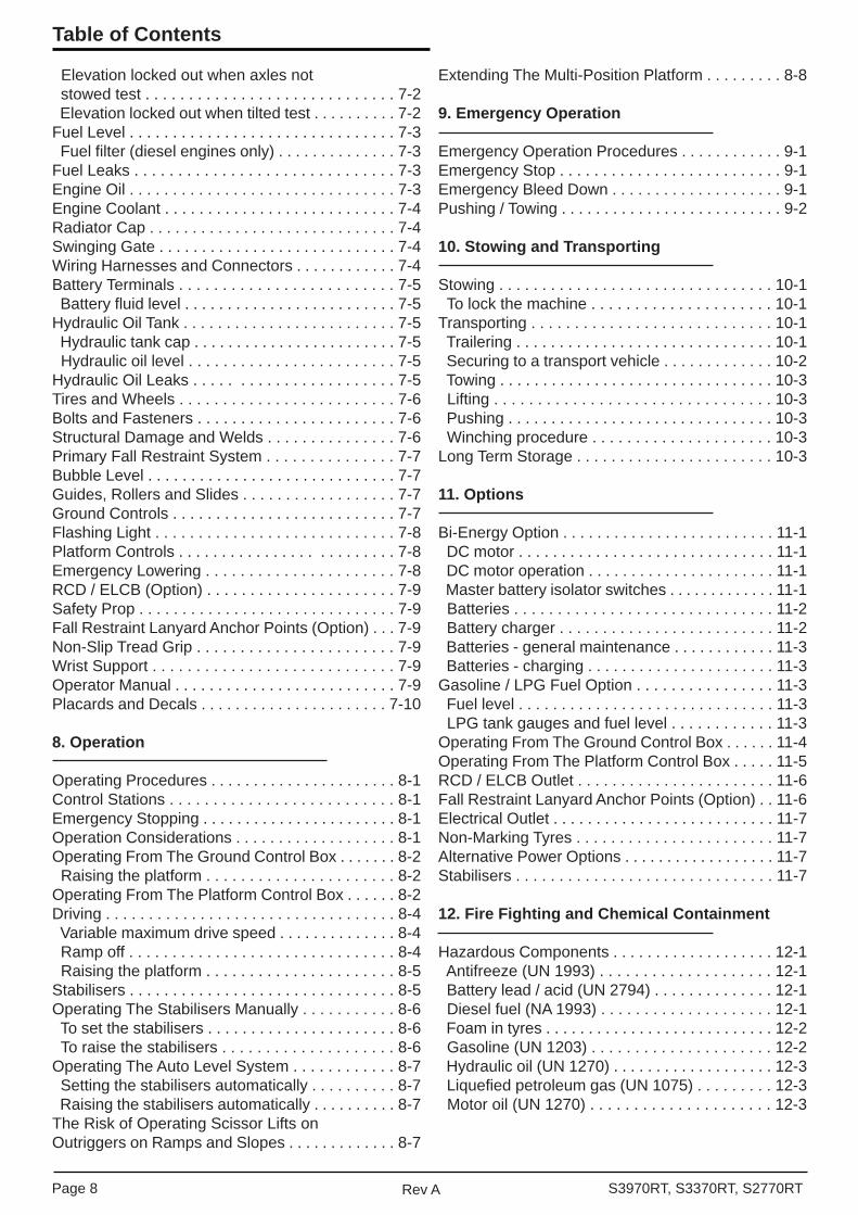
Elevation locked out when axles not stowed test . . . . . . . . . . . . . . . . . . . . . . . . . . . . . 7-2 Elevation locked out when tilted test . . . . . . . . . . 7-2Fuel Level . . . . . . . . . . . . . . . . . . . . . . . . . . . . . . . 7-3 Fuel fi lter (diesel engines only) . . . . . . . . . . . . . . 7-3Fuel Leaks . . . . . . . . . . . . . . . . . . . . . . . . . . . . . . 7-3Engine Oil . . . . . . . . . . . . . . . . . . . . . . . . . . . . . . . 7-3Engine Coolant . . . . . . . . . . . . . . . . . . . . . . . . . . . 7-4Radiator Cap . . . . . . . . . . . . . . . . . . . . . . . . . . . . . 7-4Swinging Gate . . . . . . . . . . . . . . . . . . . . . . . . . . . . 7-4Wiring Harnesses and Connectors . . . . . . . . . . . . 7-4Battery Terminals . . . . . . . . . . . . . . . . . . . . . . . . . 7-5 Battery fl uid level . . . . . . . . . . . . . . . . . . . . . . . . . 7-5Hydraulic Oil Tank . . . . . . . . . . . . . . . . . . . . . . . . . 7-5 Hydraulic tank cap . . . . . . . . . . . . . . . . . . . . . . . . 7-5 Hydraulic oil level . . . . . . . . . . . . . . . . . . . . . . . . 7-5Hydraulic Oil Leaks . . . . . . . . . . . . . . . . . . . . . . . 7-5Tires and Wheels . . . . . . . . . . . . . . . . . . . . . . . . . 7-6Bolts and Fasteners . . . . . . . . . . . . . . . . . . . . . . . 7-6Structural Damage and Welds . . . . . . . . . . . . . . . 7-6Primary Fall Restraint System . . . . . . . . . . . . . . . 7-7Bubble Level . . . . . . . . . . . . . . . . . . . . . . . . . . . . . 7-7Guides, Rollers and Slides . . . . . . . . . . . . . . . . . . 7-7Ground Controls . . . . . . . . . . . . . . . . . . . . . . . . . . 7-7Flashing Light . . . . . . . . . . . . . . . . . . . . . . . . . . . . 7-8Platform Controls . . . . . . . . . . . . . . . . . . . . . . . . . 7-8Emergency Lowering . . . . . . . . . . . . . . . . . . . . . . 7-8RCD / ELCB (Option) . . . . . . . . . . . . . . . . . . . . . . 7-9Safety Prop . . . . . . . . . . . . . . . . . . . . . . . . . . . . . . 7-9Fall Restraint Lanyard Anchor Points (Option) . . . 7-9Non-Slip Tread Grip . . . . . . . . . . . . . . . . . . . . . . . 7-9Wrist Support . . . . . . . . . . . . . . . . . . . . . . . . . . . . 7-9Operator Manual . . . . . . . . . . . . . . . . . . . . . . . . . . 7-9Placards and Decals . . . . . . . . . . . . . . . . . . . . . . 7-10
8. Operation
Operating Procedures . . . . . . . . . . . . . . . . . . . . . . 8-1Control Stations . . . . . . . . . . . . . . . . . . . . . . . . . . 8-1Emergency Stopping . . . . . . . . . . . . . . . . . . . . . . . 8-1Operation Considerations . . . . . . . . . . . . . . . . . . . 8-1Operating From The Ground Control Box . . . . . . . 8-2 Raising the platform . . . . . . . . . . . . . . . . . . . . . . 8-2Operating From The Platform Control Box . . . . . . 8-2Driving . . . . . . . . . . . . . . . . . . . . . . . . . . . . . . . . . . 8-4 Variable maximum drive speed . . . . . . . . . . . . . . 8-4 Ramp off . . . . . . . . . . . . . . . . . . . . . . . . . . . . . . . 8-4 Raising the platform . . . . . . . . . . . . . . . . . . . . . . 8-5Stabilisers . . . . . . . . . . . . . . . . . . . . . . . . . . . . . . . 8-5Operating The Stabilisers Manually . . . . . . . . . . . 8-6 To set the stabilisers . . . . . . . . . . . . . . . . . . . . . . 8-6 To raise the stabilisers . . . . . . . . . . . . . . . . . . . . 8-6Operating The Auto Level System . . . . . . . . . . . . 8-7 Setting the stabilisers automatically . . . . . . . . . . 8-7 Raising the stabilisers automatically . . . . . . . . . . 8-7The Risk of Operating Scissor Lifts onOutriggers on Ramps and Slopes . . . . . . . . . . . . . 8-7
Extending The Multi-Position Platform . . . . . . . . . 8-8
9. Emergency Operation
Emergency Operation Procedures . . . . . . . . . . . . 9-1Emergency Stop . . . . . . . . . . . . . . . . . . . . . . . . . . 9-1Emergency Bleed Down . . . . . . . . . . . . . . . . . . . . 9-1Pushing / Towing . . . . . . . . . . . . . . . . . . . . . . . . . . 9-2
10. Stowing and Transporting
Stowing . . . . . . . . . . . . . . . . . . . . . . . . . . . . . . . . 10-1 To lock the machine . . . . . . . . . . . . . . . . . . . . . 10-1Transporting . . . . . . . . . . . . . . . . . . . . . . . . . . . . 10-1 Trailering . . . . . . . . . . . . . . . . . . . . . . . . . . . . . . 10-1 Securing to a transport vehicle . . . . . . . . . . . . . 10-2 Towing . . . . . . . . . . . . . . . . . . . . . . . . . . . . . . . . 10-3 Lifting . . . . . . . . . . . . . . . . . . . . . . . . . . . . . . . . 10-3 Pushing . . . . . . . . . . . . . . . . . . . . . . . . . . . . . . . 10-3 Winching procedure . . . . . . . . . . . . . . . . . . . . . 10-3Long Term Storage . . . . . . . . . . . . . . . . . . . . . . . 10-3
11. Options
Bi-Energy Option . . . . . . . . . . . . . . . . . . . . . . . . . 11-1 DC motor . . . . . . . . . . . . . . . . . . . . . . . . . . . . . . 11-1 DC motor operation . . . . . . . . . . . . . . . . . . . . . . 11-1 Master battery isolator switches . . . . . . . . . . . . . 11-1 Batteries . . . . . . . . . . . . . . . . . . . . . . . . . . . . . . 11-2 Battery charger . . . . . . . . . . . . . . . . . . . . . . . . . 11-2 Batteries - general maintenance . . . . . . . . . . . . 11-3 Batteries - charging . . . . . . . . . . . . . . . . . . . . . . 11-3Gasoline / LPG Fuel Option . . . . . . . . . . . . . . . . 11-3 Fuel level . . . . . . . . . . . . . . . . . . . . . . . . . . . . . . 11-3 LPG tank gauges and fuel level . . . . . . . . . . . . 11-3Operating From The Ground Control Box . . . . . . 11-4Operating From The Platform Control Box . . . . . 11-5RCD / ELCB Outlet . . . . . . . . . . . . . . . . . . . . . . . 11-6Fall Restraint Lanyard Anchor Points (Option) . . 11-6Electrical Outlet . . . . . . . . . . . . . . . . . . . . . . . . . . 11-7Non-Marking Tyres . . . . . . . . . . . . . . . . . . . . . . . 11-7Alternative Power Options . . . . . . . . . . . . . . . . . . 11-7Stabilisers . . . . . . . . . . . . . . . . . . . . . . . . . . . . . . 11-7
12. Fire Fighting and Chemical Containment
Hazardous Components . . . . . . . . . . . . . . . . . . . 12-1 Antifreeze (UN 1993) . . . . . . . . . . . . . . . . . . . . 12-1 Battery lead / acid (UN 2794) . . . . . . . . . . . . . . 12-1 Diesel fuel (NA 1993) . . . . . . . . . . . . . . . . . . . . 12-1 Foam in tyres . . . . . . . . . . . . . . . . . . . . . . . . . . . 12-2 Gasoline (UN 1203) . . . . . . . . . . . . . . . . . . . . . 12-2 Hydraulic oil (UN 1270) . . . . . . . . . . . . . . . . . . . 12-3 Liquefi ed petroleum gas (UN 1075) . . . . . . . . . 12-3 Motor oil (UN 1270) . . . . . . . . . . . . . . . . . . . . . 12-3
Table of Contents

S3970RT, S3370RT, S2770RTRev APage 9
13. Operator’s Troubleshooting
Troubleshooting . . . . . . . . . . . . . . . . . . . . . . . . . 13-1 Operators troubleshooting chart . . . . . . . . . . . . 13-1
Appendix A. Glossary
Table of Contents

Page 10 Rev A S3970RT, S3370RT, S2770RT

• Drop offs or holes• Side slopes• Bumps and fl oor obstructions• Debris• Overhead obstructions & electrical conductors• Hazardous locations• Inadequate surface and support to withstand all
load forces imposed by the aerial platform in all operating confi gurations
• Wind and weather conditions• Presence of unauthorised persons• Other possible unsafe conditions
Before the S3970RT / S3370RT / S2770RT is used, determine the hazard classifi cation of any particular atmosphere or location according to ANSI/NFPA 505-1987.Any S3970RT / S3370RT / S2770RT operated in a hazardous location must be approved and of the type required by ANSI/NFPA 505-1987.While operating the S3970RT / S3370RT / S2770RT a recommended safety practice is to have trained and qualifi ed personnel in the immediate work area of the machine to:
• Help in case of an emergency• Operate emergency controls as required• Watch for loss of control by platform operator• Warn the operator of any obstructions or hazards
that may not be obvious to them• Watch for soft terrain, sloping surfaces, drop offs,
etc, where stability could be jeopardized• Watch for bystanders and never allow anyone to
be under, or to reach through the booms while operating the aerial platform.
DANGER
Pinch points may exist between moving compo-nents. Death or Serious injury can result from be-coming trapped between components, buildings, structures or other obstacles. Make sure there is suffi cient clearance around the machine before moving the chassis, booms or platform. Allow suffi cient room and time to stop movement to avoid contact with structures or other hazards.
Keep ground personnel from under the platform when the platform is raised.
Secure all accessories, containers, tools and other materials in the platform to prevent them from accidentally falling or being kicked off the platform.
Safe Operation
Knowledge of the information in this manual, and proper training, provide a basis for safely operating the S3970RT / S3370RT / S2770RT. Know the loca-tion of all the controls and how they operate to act quickly and responsibly in an emergency.Safety devices reduce the likelihood of an accident. Never disable, modify or ignore any safety device. Safety alerts in this manual indicate situations where accidents may occur.If any malfunction, hazard or potentially unsafe condition relating to capacity, intended use or safe operation is suspected, stop the operation of the S3970RT / S3370RT / S2770RT and seek assis-tance.The operator bears ultimate responsibility for fol-lowing all manufacturers instructions and warnings, regulations and safety rules of their employer and/or any country or regional law.
Electrocution Hazards
The S3970RT / S3370RT / S2770RT is an all metal aerial work platform and is not electrically insulated. Do not operate it near electrical conductors. Regard all conductors as being energised. Do not operate outside during a thunderstorm.
Pre-start Inspection
At the start of each work shift, the S3970RT / S3370RT / S2770RT shall be given a visual inspec-tion and function test. See the Daily Inspection and Maintenance chapter in this manual for a list of items to inspect and test.
WARNING
DO NOT operate the S3970RT / S3370RT / S2770RT unless you are trained and authorised, understand the operation characteristics of the machine and have inspected and tested all functions to be sure they are in proper working order.
Work Place Inspection and Practices
Do not use the S3970RT / S3370RT / S2770RT as a ground for welding, Ground to the work piece.
Before the S3970RT / S3370RT / S2770RT is used, and during use, check the area in which the machine is to be used for possible hazards such as:
S3970RT, S3370RT, S2770RTRev APage 1-1
1. Safety
Always look in the direction of travel. Drive with care and at speeds compatible with the workplace condi-tions. Use caution when driving over rough ground, on slopes, and when turning.
Do not engage in any form of horse play or stunt driving while operating the S3970RT / S3370RT / S2770RT and do not permit riders on the machine any place other than on the platform.
Remove all loose objects stored in or on the machine, particularly in the platform. Remove all objects which do not belong in or on the machine.
Never steady the platform by positioning it against another platform.
Do not operate an S3970RT / S3370RT / S2770RT that is damaged or not functioning properly. Do not use the S3970RT / S3370RT / S2770RT until the machine has been repaired by a qualifi ed mainte-nance person.
Do not operate a S3970RT / S3370RT / S2770RT that does not have all its decals and placards attached and legible.
Watch for bystanders and never allow any one to be under, or to reach through, the machine and its equipment while operating.
Use the recommended transport device when loading the machine.
Operation
ENSURE that you wear appropriate PPE while using the machine. The required PPE will vary depending on the specifi c job. A risk and hazard analysis must be performed by the operator to understand what PPE will be required.
DO NOT operate the machine if you feel tired, sick or if you are under the infl uence alcohol, prescription or illicit drugs.
If you encounter any suspected malfunction of the aerial platform, or any hazard or potentially unsafe condition relating to capacity, intended use or safe operation, cease operation immediately and seek assistance from management.
Use three (3) points of support when getting on or off the platform (two (2) hands and one (1) foot or a similar set of points). Keep the platform clean.
Maintain a fi rm footing on the platform fl oor. Operate the controls slowly and deliberately to avoid jerky and erratic operation. Always stop the controls in neutral before going in the opposite direction.
Do not dismount while the platform is in motion or jump off the machine. Do not start until all personnel are clearly away from the machine.
Never cover the fl oor grating or otherwise obstruct your view below. Make sure the area below the platform is free of personnel before lowering.
Access and egress from the platform is to be attempt-ed ONLY when the platform is fully lowered.
DO NOT overload the platform by lifting additional equipment from an elevated platform.
The S3970RT / S3370RT / S2770RT is not intended for on-road use. The machine may be used on the road if applicable control measures are in place and local regulations are adhered to. Operators of the S3970RT / S3370RT / S2770RT MUST NOT push or pull objects with the platform.
Tipover and Falling Hazards
Operate the machine only on a fi rm, fl at level surface capable of withstanding all load forces imposed by the S3970RT / S3370RT / S2770RT in all operating conditions.
DANGER
The machine can tip over if it becomes unstable. Death or serious injury can result from a tip over accident. Do not drive or position the S3970RT / S3370RT / S2770RT platform for elevated use near any drop-offs, hole, slope, soft or uneven ground, or other tip-over hazard.
Do not operate the machine from a position on trucks, trailers, railway cars, fl oating vessels, scaffolds or similar equipment unless the application is approved in writing by Snorkel.
Care shall be taken to prevent rope, electrical cords and hoses etc from becoming entangled in the aerial platform. If the platform or elevating assembly becomes caught, snagged or otherwise prevented from normal motion by an adjacent structure or otherobstacle such that control reversal does not free the platform, remove all personnel from the platform before attempts are made to free the platform using ground controls.
Page 1-2 Rev A S3970RT, S3370RT, S2770RT
1. Safety

No person shall access or egress from the platform in the elevated position (except in an emergency) un-less the requirements of AS2550.10 have been met. For full requirements refer directly to AS2550.10.
Do not exceed the restricted platform capacity as in-dicated on the capacity placard at the entrance to the platform. Do not carry loads from any point outside of the platform.
Make sure that all protective guards, cowlings and doors are in place and secure. Be sure the guard rail system, including the gate, is in place and secure.
Do not climb on the guardrails or use ladders, planks or other devices to extend or increase your work position from the platform.
Do not use the machine as a crane, hoist or jack, or for any other purpose other than to position person-nel, their tools and materials.
Do not operate the machine in winds, or wind gusts of 28 mph, 45 km/h 12.5 m/s or more.
DANGER
Do not add banners, fl ags, screens or shelters etc to areas of the S3970RT / S3370RT / S2770RT that are exposed to wind forces as this will increase the wind loading and effect stability.
General Safety Precautions
Do not modify the S3970RT / S3370RT / S2770RT in any way.
When parts or components are replaced, they shall be identical or equivalent to original Snorkel parts or components.
Do not override any of the safety features of the S3970RT / S3370RT / S2770RT. Ensure that the ma-chine is secure from any unauthorised use.
Hydraulic System Precautions
The hydraulic system contains hoses with hydraulic fl uid under pressure.
DANGER
Hydraulic fl uid escaping under pressure can have enough force to inject fl uid into the fl esh. Serious infection or reaction can result if medical treatment is not given immediately. In case of emergency by
escaping hydraulic fl uid, seek medical attention at once.
DO NOT place your hand or any part of your body in front of escaping hydraulic fl uid. Use a piece of card-board or wood to search for hydraulic leaks.
Do not attempt repairs to hydraulic systems unless you are trained. Refer to experienced repair person-nel for help.
Fire / Explosion Prevention
Never operate your S3970RT / S3370RT / S2770RT near a fl ame or spark. Hydraulic oil and gasoline are fl ammable and can explode.
DO NOT operate the machine in an explosive envi-ronment unless the machine is suitably modifi ed by an authorised agent of the manufacturer.
DO NOT carry fuel or other fl ammable or explosive or toxic substances in the platform unless a risk and hazard analysis shows that it is safe to do so and that applicable control measures are in place e.g. carry only the minimum amount required and in approved containers etc.
Engine and Fuel Handling Precautions
Engine exhaust contains carbon monoxide, a poisonous gas that is invisible and odorless. Breathing engine exhaust fumes can cause death or serious illness. Do not run the engine in an en-closed area or indoors without adequate ventila-tion.Only refuel your machine outdoors in a clear area void of gas fumes or spilled gas. Never remove the fuel cap or refuel a gasoline engine while the engine is running or hot. ALWAYS allow the engine to cool before refueling. Never allow fuel to spill on hot machine components.
CAUTION
DO NOT smoke or permit open fl ames while fueling or near fueling operations.Maintain control of the fuel fi lter nozzle when fi lling the tank.
WARNING
ENSURE you use an approved fuel container with appropriate fuel fi lter nozzle.Do not fi ll the tank to capacity. Allow room for expan-sion.
S3970RT, S3370RT, S2770RTRev APage 1-3
1. Safety

If gasoline is spilled, clean up the spilled fuel immedi-ately, push/tow the S3970RT / S3370RT / S2770RT away from the area of the spill and avoid creating any source of ignition until the spilled fuel has evap-orated.
Tighten the fuel tank cap securely. If the fuel cap is lost, replace it with an approved fuel cap from Snorkel. Use of a non-approved cap without proper venting may result in pressurization of the tank.
Never use fuel for cleaning purposes.
For diesel engines, use the correct fuel grade for the operating season.
Batteries
Charge batteries in a well ventilated area free of fl ame, sparks or other hazards that might cause fi re or explosion.
WARNING
Batteries give off hydrogen and oxygen that can combine explosively. Death or serious injury can result from a chemical explosion. Do not smoke or permit open fl ames or sparks when checking batteries.Battery acid can damage the skin and eyes. Serious infection or reaction can result if medi-cal treatment is not given immediately. Wear face and eye protection when working near batteries.
Batteries contain sulfuric acid that can damage your eyes or skin on contact. Wear a face shield, rubber gloves and protective clothing when working around batteries. If acid contacts your eyes, fl ush immediate-ly with clear water and get medical attention. If acid contacts your skin, wash off immediately with clear water.
Safety Decals and Placards
There are several safety decals and placards on the S3970RT / S3370RT / S2770RT. Their locations and descriptions are shown in this section. Take time to study them.
CAUTION
Be sure that all the safety decals and placards on the S3970RT / S3370RT / S2770RT are legible. Clean or replace them if you cannot see the pic-tures. Clean with soap & water and a soft cloth. Do not use solvents.
You MUST replace a decal or placard if it is dam-aged, missing or cannot be read. If it is on a part that is replaced, make sure a new decal or placard is installed on the replaced part. See your Snorkel dealer for new decals and placards.
Note:From time-to-time certain snorkel decals may be deleted, altered or replaced, or new decals may be added in line with new safety regulations or machine specifi cation changes.
If you are unsure or want to check a particular decal or its placement on the machine contact your nearest Snorkel dealer or the Snorkel website.
Safety Placards and Decals Location
Page 1-4 Rev A S3970RT, S3370RT, S2770RT
1. Safety

LEFT HAND SIDE OF THE MACHINE
On Fuel Tank Inside Cabinet &Outside Of Cabinet Door
0372061
TORQUE
�90-100 Ft. Lbs.122-135 N mLug Bolts/Nuts
Check Every 30 Days
501453-000All 4 Stabilisers
S3970RT, S3370RT, S2770RTRev APage 1-5
1. Safety

RIGHT-HAND SIDE OF MACHINE
STORAGE POSITIONPROPER POSITION FOR USE
SAFETY BAR 24”
YOU MUST NOT OPERATE THIS DEVICE UNLESS:
AN UNTRAINED OPERATOR SUBJECTS HIMSELF AND OTHERS TO
DEATH OR SERIOUS INJURY.
0323897
1.
2.
YOU HAVE BEEN TRAINED IN THE SAFE OPERATION OF THISDEVICE AND HHHH
YOU KNOW AND FOLLOW THE SAFETY AND OPERATINGRECOMMENDATIONS CONTAINED IN THE MANUFACTURER'SMANUALS, YOUR EMPLOYER'S WORK RULES, AND APPLI-CABLE GOVERNMENTAL REGULATIONS. HHHHHHHH
DANGER
DANGER
300700
SHEARING HAZARD/CRUSHING HAZARDDeath or serious injury might result from having body parts sheared or crushed as the platform descends. Keep away from closing scissor arms and keep out from under the platform as the platform comes down.
0372061
TORQUE
�90-100 Ft. Lbs.122-135 N mLug Bolts/Nuts
Check Every 30 Days
0372061
TORQUE
�90-100 Ft. Lbs.122-135 N mLug Bolts/Nuts
Check Every 30 Days
EMERGENCY OPERATION
1. EMERGENCY LOWERINGIn the event of total power failure pull the emergency lowering handle
[A] mounted at the front of the chassis until the platform starts to
descend. Once the platform is lowered the handle can be released.
2. TOWING OR PUSHING THE MACHINE
Free-wheel the Drive Motors
DANGERA runaway machine can cause death or Serious Injury. Do Not
proceed unless the machine is on a level surface or is attached
to an object that can hold the machine on a slope.
CAUTIONThe machines Drive motors will be ruined if the machine
is pushed or towed faster than 3.2 kph (2 mph).
In order to push or tow the machine the following steps
MUST be taken.
Open the free-wheeling valve [A] by turning counterclockwise until the
knob stops.
Release the Brakes
To release the brakes, pump the hand pump [B] 5 - 10 times. The brakes
will now be released and the machine is ready to be pushed / towed.
Resetting the Brakes
Once the machine has been safely pushed / towed it is IMPORTANT to
re-apply the brakes by pulling the re-set valve [C] and close the free-
wheel valve [A] by turning fully clockwise.
A
B
C
Free-wheel
Valve
Hand
Pump
Brakes Re-Set
Valve
13601-1
A
Page 1-6 Rev A S3970RT, S3370RT, S2770RT
1. Safety

FRONT END OF THE MACHINE
DEATH OR SERIOUS INJURY CAN RESULT FROM TIPPING OVER.TO KEEP FROM TIPPING THIS MACHINE OVER FOLLOW THESE RULES.
OTHER ACTIONS CAN ALSO CAUSE THIS MACHINE TO TIP OVER
NOTE: STUDY THE OPERATOR'S MANUAL BEFORE OPERATING THIS MACHINE.12574
DO NOT override safety devices.
DO NOT overload the machine.
DO NOT stand or sit on guardrails.
DO NOT attach ropes or chains to guardrails.
DO NOT carry loads outside the railing or use as a crane.
DO NOT use this machine without the railings and the entry gate in place. You could fall out and hurt or kill yourself.
DO NOT use this machine if it is not operating correctly, or if any part of it is damaged, worn, or missing. An accident could cause injury or death.
DO NOT let an untrained or unauthorized person use this machine. When you leave the machine unattended, remove the key, or turn off the battery switch on the base of the machine and lock the battery switch in the off position.
DO NOT replace components critical to machine stability, such as batteries and wheel equipment, with lighter
DO NOT ride platform while machine is on a truck, fork lift or other device.
DO NOT use ladder, scaffold, or other means to increase size or platform height.
DO NOT use with improperly inflated or damaged tires or wheels.
DO NOT RAISE OR DRIVE AN ELEVATEDPLATFORM ON
SOFT OR UNEVENSURFACES
DO NOT RAISE OR DRIVE AN ELEVATEDPLATFORM ON A
SLOPE
GO NO CLOSER THAN 4 feet (1.2m)to ANY DROP OFF
OR HOLE
4 FT/1.2M
OK
1. 3.2.
TWO-TONE ALARM MEANS TIPOVER DANGER!LOWER PLATFORM IMMEDIATELY
TO AVOIDTIPOVER HAZARDS
USE ONFLAT, LEVEL, ANDSOLID SURFACES
ONLY
OK
DO NOT RAISE A PLATFORMIN WIND ABOVE 28 MPH (12.5 M/S)
4 FT/1.2M
WARNINGKEEP LINESCLEAR POWEROFUnless the Electrical Supply Authority has advised
in writing otherwise;the clearance between any live overheadpower line and any part of this machine or
load carried is required by law to be
AT LEAST 4 METRESThis is a requirement of regulation 93 of the
Electrical Supply Regulations 1984in the interests of safe working.
EMERGENCY BLEEDDOWN VALVE
12753
Australia Only
New Zealand Only
ALL DECALS ON REVERSE SIDE
On Top Of Chassis Member
S3970RT, S3370RT, S2770RTRev APage 1-7
1. Safety

REAR END OF THE MACHINE
S3370RT
S2770RT
11346-1
90 lb(400 N) Max
28 mph(12.5 m/s)
90 lb(400 N) Max
0 mph(0 m/s)
315 lb(140 kg)
lbkg
875 lb(400 kg)
400 lb(180 kg)
700 lb(320 kg)
1015 lb(460 kg)
1275 lb(580 kg)
lbkg
85 lb(40 kg)
lbkg
175 lb(80 kg)
260 lb(120 kg)
85 lb(40 kg)
lbkg
175 lb(80 kg)
260 lb(120 kg)
400 lb(180 kg)
lbkg
875 lb(400 kg)
1275 lb(580 kg)
315 lb(140 kg)
lbkg
700 lb(320 kg)
1015 lb(460 kg)
12699
90 lb(400 N) Max
28 mph(12.5 m/s)
90 lb(400 N) Max
0 mph(0 m/s)
40 lb(10 kg)
lbkg
875 lb(400 kg)
125 lb(50 kg)
700 lb(320 kg)
740 lb(330 kg)
1000 lb(450 kg)
lbkg
85 lb(40 kg)
lbkg
175 lb(80 kg)
260 lb(120 kg)
85 lb(40 kg)
lbkg
175 lb(80 kg)
260 lb(120 kg)
650 lb(290 kg)
lbkg
350 lb(160 kg)
1000 lb(450 kg)
565 lb(250 kg)
lbkg
175 lb(80 kg)
740 lb(330 kg)
12699-4
90 lb(400 N) Max
28 mph(12.5 m/s)
90 lb(400 N) Max
0 mph(0 m/s)
335 lb(150 kg)
lbkg
875 lb(400 kg)
420 lb(190 kg)
700 lb(320 kg)
510 lb(230 kg)
770 lb(350 kg)
lbkg
85 lb(40 kg)
lbkg
175 lb(80 kg)
260 lb(120 kg)
85 lb(40 kg)
lbkg
175 lb(80 kg)
260 lb(120 kg)
420 lb(190 kg)
lbkg
350 lb(160 kg)
770 lb(350 kg)
335 lb(150 kg)
lbkg
175 lb(80 kg)
510 lb(230 kg)
S3970RT
Page 8 Rev A S3970RT, S3370RT, S2770RT
1. Safety
Safety Device Information
For emergency operation controls and procedures see the Emergency Operation, Chapter 9, in this manual.
The devices listed in this chapter are safety devices.They are on the machine to increase safety in the workplace for both the operator and other people near the machine.
WARNING
Do not bypass, disable, modify or ignore any of these devices. Check them carefully at the start of each work shift to see that they are in work-ing order (see daily inspection & maintenance) chapter 7. If any is found to be defective, remove the S3970RT / S3370RT / S2770RT from service immediately until a qualifi ed service technician can make repairs.
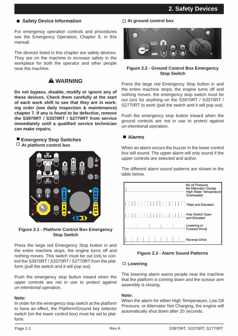
Emergency Stop Switches At platform control box
Figure 2.1 - Platform Control Box Emergency Stop Switch
Press the large red Emergency Stop button in and the entire machine stops, the engine turns off and nothing moves. This switch must be out (on) to con-trol the S3970RT / S3370RT / S2770RT from the plat-form (pull the switch and it will pop out).
Push the emergency stop button inward when the upper controls are not in use to protect against un-intentional operation.
Note:In order for the emergency stop switch at the platform to have an effect, the Platform/Ground key selector switch (on the lower control box) must be set to plat-form.
At ground control box
Figure 2.2 - Ground Control Box EmergencyStop Switch
Press the large red Emergency Stop button in and the entire machine stops, the engine turns off and nothing moves. the emergency stop switch must be out (on) for anything on the S3970RT / S3370RT / S2770RT to work (pull the switch and it will pop out).
Push the emergency stop button inward when the ground controls are not in use to protect against un-intentional operation.
Alarms
When an alarm occurs the buzzer in the lower control box will sound. The upper alarm will only sound if the upper controls are selected and active.
The different alarm sound patterns are shown in the table below.
Figure 2.3 - Alarm Sound Patterns
Lowering
The lowering alarm warns people near the machine that the platform is coming down and the scissor arm assembly is closing.
Note:When the alarm for either High Temperature, Low Oil Pressure, or Alternator Not Charging, the engine will automatically shut down after 20 seconds.
S3970RT, S3370RT, S2770RTRev APage 2-1
2. Safety Devices

High temperature
The high temperature alarm warns you that the engine is overheating. (See Automatic Shut-offs and Circuit Breakers chapter 5 for more information).
Low oil pressure
The low oil pressure alarm warns you that the engineoil pressure is near the lower limit for safe operation of the engine. (See Automatic Shut-offs & Circuit breakers chapter 5 for more information).
Alternator not charging
This alarm warns you that the alternator is not charging the battery. (See Automatic Shut-offs and Circuit Breakers chapter 5 for more information).
Drive (reverse)
The DRIVE (reverse) alarm alerts people that the S3970RT / S3370RT / S2770RT is traveling back-wards along the ground. This alarm beeps twice as fast as the DRIVE (forward) alarm.
Drive (forward)
The DRIVE forward alarm alerts people that the S3970RT / S3370RT / S2770RT is traveling forward along the ground. The alarm beeps half as fast as the DRIVE (reverse) alarm.
Load Sensing System
As soon as the scissor stack rises from its stowed position the overload protection system becomes active.
• If 90% of rated capacity is reached in the platform the overload light will illuminate.
This is a warning to the operator that the platform is reaching rated capacity. Normal function will remain and the machine can continue to be used.
• If 100% of the rated capacity is reached in the platform the overload light will continue to be illuminated and an alarm will sound.
This is a warning to the operator that rated capacity has been reached and the platform load must be re-duced. Normal function will remain to allow the plat-form to be positioned to remove some load from the platform.
Note:The machine should not be operated continuously with the overload alarm sounding.
• if 110% of rated capacity is reached in the platform the overload light will continue to be illuminated and an alarm will continue to sound and all functions will be disabled.
The operator must remove load from the platform.
Normal function will resume once the platform load has been reduced below 110% continuously for at least two (2) seconds.
Figure 2.4 - Platform Overload Light
Level Sensor
The level sensor alarm warns the S3970RT / S3370RT / S2770RT operator that the machine is not level.When you hear this alarm, immediately lower the platform completely down. When the platform is com-pletely down, determine and correct the cause of the tilt before raising the platform again.
Note:While the alarm is sounding it is not possible to drive the S3970RT / S3370RT / S2770RT nor raise the platform.
Primary Fall Restraint System
Figure 2.5 - Fall Restraint
Page 2-2 Rev A S3970RT, S3370RT, S2770RT
2. Safety Devices

The handrails, including mid-rail and toe board combined with the gate, form a Fall Restraint System.The System Prevents the operator from reaching the Fall Hazard. Ensure that all handrails are located correctly with each other and that all pins and bolts are in place.
If any part of the Fall Restraint System is not in place the System is compromised and the operator must review the Risk and Hazard analysis and determine ways to provide adequate fall protection e.g. the use of Fall Restraint Harnesses, Lanyards and Anchors.
Safety Prop
Figure 2.6 - Safety Prop
Always raise the safety prop then lower the scissor arm assembly onto the safety prop before reaching into the scissor arm assembly for any reason.
Swinging Gate
Figure 2.7 - Swinging Gate
The swinging gate should be closed all times except when someone is entering or leaving the platform.
Safety Control
Figure 2.8 - Joystick Safety Control
The safety control must be squeezed and held to activate the joystick. The safety control prevents the joystick from moving the platform if something accidentally pushes the joystick. Do not attempt to disable the safety control in any way.
Bubble Level
Figure 2.9 - Bubble Level
See the gauges chapter 4 for a discussion of the bubble level.
Operator Horn
Figure 2.10 - Operator Horn
The operator horn is used primarily to get the atten-tion of people on the ground when you are working aloft. for the horn to work, the following switches on the ground control box, must be set as indicated.
S3970RT, S3370RT, S2770RTRev APage 2-3
2. Safety Devices

MAIN POWER.................................ONEMERGENCY STOP.......................ON (up)SELECTOR.....................................PLATFORM
Stabilisers (Option)
Figure 2.11 - Stabilisers
The stabiliser controls are on the upper left side of the platform control box. The stabilisers are used to level the S3970RT / S3370RT / S2770RT (for complete stabiliser operating procedures see the Op-eration chapter 8).
NoteThe S3970RT / S3370RT / S2770RT must be on a fi rm surface capable of withstanding all load forces imposed by by the aerial platform in all operation conditions before the stabilisers are used.
Rough Terrain Scissor Interlock Tests
All Snorkel scissor lifts in the Snorkel SRT, SR & S/RT series are fi tted with a very important safety feature, a ‘Stabiliser/axle/scissor Interlock’ system that prevents the stabilisers being moved while the platform is elevated, and prevents the platform being raised if the rear axle is oscillated and the stabilisers are not set or the machine is tilted.
IMPORTANT
The correct operation of the stabiliser/scissor Interlock is critical to ensure that the Scissor is operated safely and with minimum risk.
Detailed instructions on how to carry out the tests to ensure that these functions are working correctly are provided at the beginning of the Pre-Operational Inspection chapter in this manual.
Enable Switch
The enable switch must be operated in conjunction with the platform moving function you select. The purpose of this switch is to prevent the platform from moving if something or someone accidentally pushes one of the platform moving controls.
Figure 2.12 - Enable Switch
RCD/ELCB Outlet (Option)
RCD
Power Outlet At Platform
Power Input Connector
Figure 2.13 - RCD/ELCB AC Outlet
The RCD (Residual Current Device) is located at the ground and will protect against short circuits to earth.When there is a short circuit the RCD will shut down the 230V AC power to the platform outlet. To reset the outlet disconnect the power tool lead from the platform box and reset the RCD at the ground, if the problem persists call a trained service technician.
Page 2-4 Rev A S3970RT, S3370RT, S2770RT
2. Safety Devices

Flashing Light
The fl ashing light alerts people that the S3970RT / S3370RT / S2770RT is present and that the machine is moving. The light fl ashes at about one (1) fl ash per second any time the engine is running. There is no ON/OFF switch for the fl ashing light, it cannot be turned off while the S3970RT / S3370RT / S2770RT is running.
Fall Restraint Lanyard Anchor Points
There are three (3) Fall Restraint Anchor points on the fl oor of the platform on the S3970RT / S3370RT / S2770RT. Two (2) behind the roll-out deck when retracted, one (1) behind the roll-out deck when extended.
DANGER
The Fall Restraint Anchor points are rated for Fall Restraint only. A Fall Arrest System must not be attached. Death or serious injury could result from use of a Fall Arrest System.
The anchor points are positioned such that a Fall Restraint Lanyard can be set short enough to pre-vent the operator reaching the fall hazard (when not all guardrails are in place) while still allowing some freedom of movement.
Note:These anchors are not for lifting or tying down the machine.You should attach your fall protection to the anchors if work rules require it.
S3970RT, S3370RT, S2770RTRev APage 2-5
2. Safety Devices

Page 2-6 Rev A S3970RT, S3370RT, S2770RT
2. Safety Devices
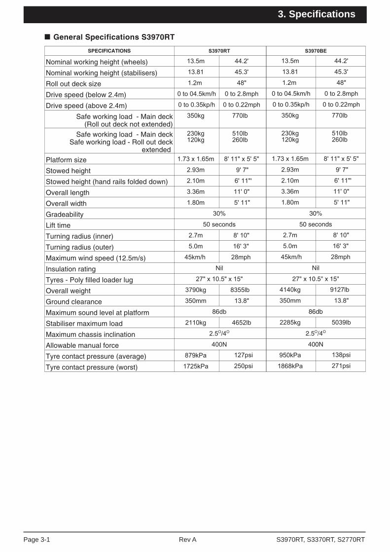
■ General Specifications S3970RT
SPECIFICATIONS
Nominal working height (wheels)
Nominal working height (stabilisers)
Roll out deck size
Drive speed (below 2.4m)
Drive speed (above 2.4m)
Safe working load - Main deck(Roll out deck not extended)
Safe working load - Main deckSafe working load - Roll out deck
extended
Platform size
Stowed height
Stowed height (hand rails folded down) '
Overall length
Overall width
Gradeability
Lift time
Turning radius (inner)
Turning radius (outer)
Maximum wind speed (12.5m/s)
Insulation rating
Tyres - Poly filled loader lug
Overall weight
Ground clearance
Maximum sound level at platform
Stabiliser maximum load
Maximum chassis inclination O O
Allowable manual force
Tyre contact pressure (average)
Tyre contact pressure (worst)
30%
50 seconds
Nil
27" x 10.5" x 15"
86db
2.5O/4O
400N
'
S3970RT, S3370RT, S2770RTRev APage 3-1
3. Specifi cations

SPECIFICATIONS
Nominal working height
Roll out deck size
Drive speed (below 2.4m)
Drive speed (above 2.4m)
Safe working load - Main deck(Roll out deck not extended)
Safe working load - Main deckSafe working load - Roll out deck extended
Platform size
Stowed height
Stowed height (hand rails folded down)
Overall length
Overall width
Gradeability
Lift time
Turning radius (inner)
Turning radius (outer)
Maximum wind speed (12.5m/s)
Insulation rating
Tyres - Poly filled loader lug
Overall weight
Ground clearance
Maximum sound level at platform
Stabiliser maximum load
Maximum chassis inclination O O
Allowable manual force
Tyre contact pressure (average)
Tyre contact pressure (worst)
■ General Specifications S3370RT
35%
50 seconds
Nil
27" x 10.5" x 15"
86db
2.5O/4O
400N
Page 3-2 Rev A S3970RT, S3370RT, S2770RT
3. Specifi cations

■ General Specifications S2770RT
SPECIFICATIONS
Nominal working height
Roll out deck size ”
Drive speed (below 2.4m)
Drive speed (above 2.4m)
Safe working load - Main deck(Roll out deck not extended)
Safe working load - Main deckSafe working load - Roll out deck extended
Platform size
Stowed height
Stowed height (hand rails folded down)
Overall length
Overall width
Gradeability
Lift time
Turning radius (inner)
Turning radius (outer)
Maximum wind speed (12.5m/s)
Insulation rating
Tyres - Poly filled loader lug
Overall weight
Ground clearance
Maximum sound level at platform
Stabiliser maximum load
Maximum chassis inclination O O
Allowable manual force
Tyre contact pressure (average)
Tyre contact pressure (worst)
”
O O
S3970RT, S3370RT, S2770RTRev APage 3-3
3. Specifi cations

Engine Oil Charts
NOTE:For further details regarding lubricants,maintenance schedules and service please referto the Maintenance and Repair Parts Manual forthis machine.
Engine Make Kubota
Model DF752 (Option) D902
Fuel gasoline LPG Diesel
Fuel grade Unleaded85 octane(motor method
Do not usegasoline blendedwith methylalcohol.
HD5
Gas ProcessorsAssociationStandard 2140
Category: specialduty propane
ASTM Grade 2-D S5000
Tier 4 Compliance:
Low SulpherASTM Grade 2-D S500
Centane number >44
(For operating temp. Below 32oF (0oC)use “winterized” number 2-D.)
Coolant 50% water + 50% ethylene glycol
Maximumtemperature
110oC
Oil Capacity 3.7L
Oil grade API: Quality better than CD
Oil weight See chart below
� Engine Data
Ambient temperature Engine oil weight
Above 77oF (25oC) SAE30 or 10W30
32oF to 77oF(0oC) to (25oC)
SAE20 or 10W30
0oF to 32oF(-17oC) to (0oC)
SAE10W or 10W30
� DF752 (Option)
Ambient temperature Engine oil weight
Above 77oF (25oC) SAE30 or 10W3010W40
32oF to 77oF(0oC) to (25oC)
SAE20 or 10W3010W40
Below 32oF (0oC) SAE10W or 10W3010W40
� D902
Page 3-4 Rev A S3970RT, S3370RT, S2770RT
3. Specifi cations

Machine Component Identifi cation
1. Extendable platform2. Entry gate3. Hydraulic compartment4. Front end5. Rear end6. Guard rails7. Steering (front) wheels8. Rear wheels9. Scissor arms10. Platform11. Platform control box12. Stabilisers / outriggers (option)
1. Base control panel2. Serial number plate3. Engine & fuel compartments
1
11
1212
12
8
74
9
3
5
10
26
1
2
3
S3970RT, S3370RT, S2770RTRev APage 3-5
3. Specifi cations

Page 3-6 Rev A S3970RT, S3370RT, S2770RT
3. Specifi cations

EzCal LCD Display
Figure 4.1 - EzCal LCD Display
The EzCal LCD display is a diagnostic tool for the control system. It is intended to be used primarily by trained technicians.
The EzCal LCD display gives some information for the machine operator.
Water
If the engine becomes to hot the EzCal LCD display will show “Shutdown - Engine Too Hot”.
Alternator
If the alternator is not providing suffi cient charge the EzCal LCD display will show “Shutdown - Not Charging”.
Oil Pressure
If the engine does not have suffi cient oil pressure the EzCAL LCD display will show “Shutdown - No Oil Pressure”.
Hours
Work time
The EzCal default state is to display machine work time. It accumulates time whenever the control system is active. This can be rest by a qualifi ed tech-nician. This value can be used to tell when periodic maintenance is due.
Total time
The total machine on time can be found by using the EzCal diagnostics under log. This can not be reset.
S3970RT, S3370RT, S2770RTRev APage 4-1
4. Gauges
Engine Oil
Engine oil is measured with a dipstick. Oil capacities given in the Specifi cations chapter 3 are approximate.True values will vary from machine to machine due to slight variations or modifi cations during production.
• The oil dipstick is the only way to accurately gauge if the engine oil is correct.
• Engine oil level should always be between the lines on the dipstick - never above the top line or below the bottom line.
Figure 4.3 - Oil Dipstick Levels for Gasolineand Diesel Engines
Hydraulic Oil Level
Figure 4.4 - Hydraulic Oil Level
The hydraulic oil level gauge is on the side of the hydraulic oil tank. It shows the actual level of the oil inside the tank. Read it only when the platform is completely down. Otherwise, the lift cylinders be-come large reservoirs for hydraulic oil and the oil in the tank will be low. the oil level should be within (0.25 inches , 6.4 mm) of the line.

Bubble Level
Figure 4.7 - Bubble Level
A bubble level is located on the platform side rail, below the platform control box. Watch the bubble level while you set the stabilisers manually. Lower the stabilisers, one at a time, just enough to set the bub-ble between the guidelines in both the fore and aft and lateral gauges. When the bubbles are centered the platform is level and can safely be raised.
Page 4-2 Rev A S3970RT, S3370RT, S2770RT
4. Gauges
Automatic Shut-offs
Level Sensor
When the level sensor alarm sounds, automatically interlocks make it impossible to drive the S3970RT / S3370RT / S2770RT or raise the platform. For more complete information see the Level Sensor subsec-tion of the Safety Devices 2 chapter.
Engine temperature
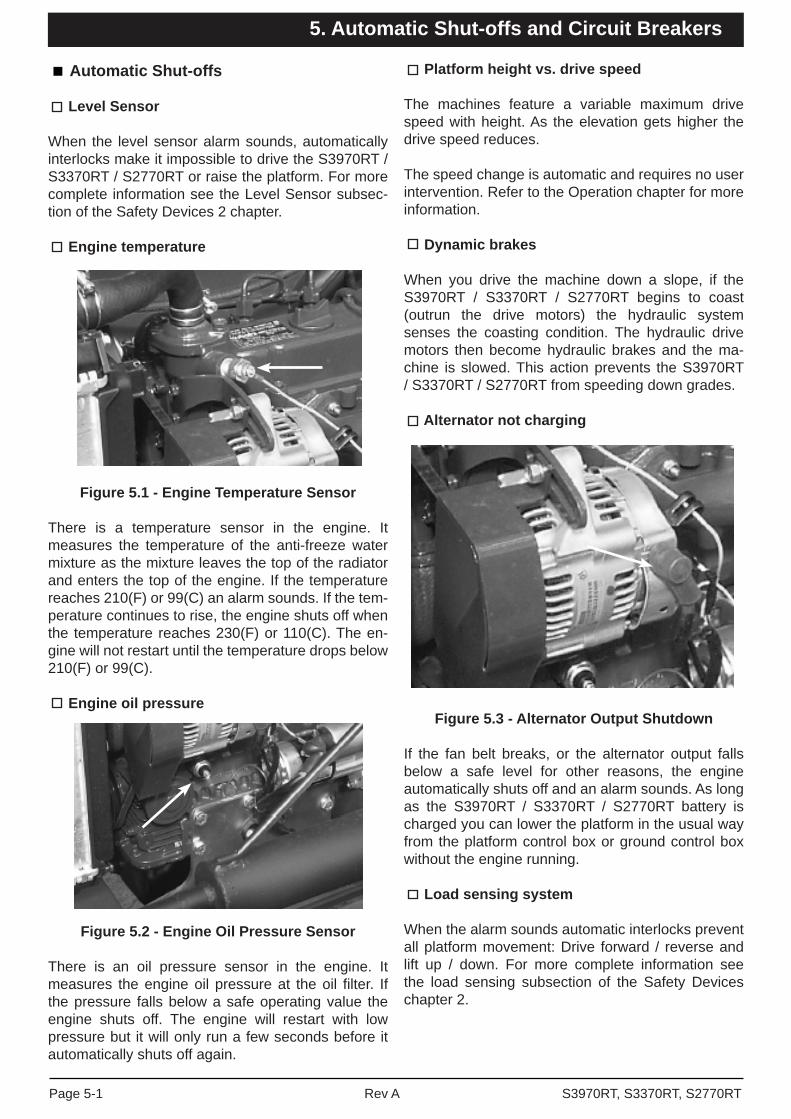
Figure 5.1 - Engine Temperature Sensor
There is a temperature sensor in the engine. It measures the temperature of the anti-freeze water mixture as the mixture leaves the top of the radiator and enters the top of the engine. If the temperature reaches 210(F) or 99(C) an alarm sounds. If the tem-perature continues to rise, the engine shuts off when the temperature reaches 230(F) or 110(C). The en-gine will not restart until the temperature drops below 210(F) or 99(C).
Engine oil pressure
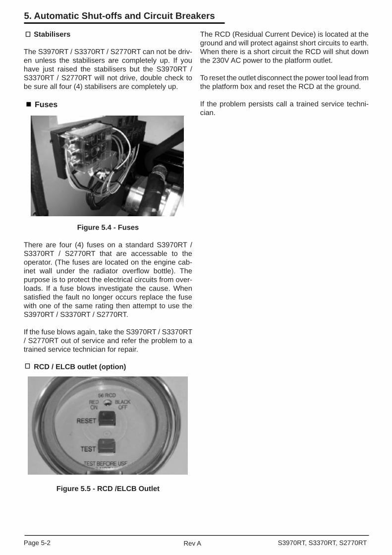
Figure 5.2 - Engine Oil Pressure Sensor
There is an oil pressure sensor in the engine. It measures the engine oil pressure at the oil fi lter. If the pressure falls below a safe operating value the engine shuts off. The engine will restart with low pressure but it will only run a few seconds before it automatically shuts off again.
Platform height vs. drive speed
The machines feature a variable maximum drive speed with height. As the elevation gets higher the drive speed reduces.
The speed change is automatic and requires no user intervention. Refer to the Operation chapter for more information.
Dynamic brakes
When you drive the machine down a slope, if the S3970RT / S3370RT / S2770RT begins to coast (outrun the drive motors) the hydraulic system senses the coasting condition. The hydraulic drive motors then become hydraulic brakes and the ma-chine is slowed. This action prevents the S3970RT / S3370RT / S2770RT from speeding down grades.
Alternator not charging
Figure 5.3 - Alternator Output Shutdown
If the fan belt breaks, or the alternator output falls below a safe level for other reasons, the engine automatically shuts off and an alarm sounds. As long as the S3970RT / S3370RT / S2770RT battery is charged you can lower the platform in the usual way from the platform control box or ground control box without the engine running.
Load sensing system
When the alarm sounds automatic interlocks prevent all platform movement: Drive forward / reverse and lift up / down. For more complete information see the load sensing subsection of the Safety Devices chapter 2.
S3970RT, S3370RT, S2770RTRev APage 5-1
5. Automatic Shut-offs and Circuit Breakers
Stabilisers
The S3970RT / S3370RT / S2770RT can not be driv-en unless the stabilisers are completely up. If you have just raised the stabilisers but the S3970RT / S3370RT / S2770RT will not drive, double check to be sure all four (4) stabilisers are completely up.
Fuses
Figure 5.4 - Fuses
There are four (4) fuses on a standard S3970RT / S3370RT / S2770RT that are accessable to the operator. (The fuses are located on the engine cab-inet wall under the radiator overfl ow bottle). The purpose is to protect the electrical circuits from over-loads. If a fuse blows investigate the cause. When satisfi ed the fault no longer occurs replace the fuse with one of the same rating then attempt to use the S3970RT / S3370RT / S2770RT.
If the fuse blows again, take the S3970RT / S3370RT / S2770RT out of service and refer the problem to a trained service technician for repair.
RCD / ELCB outlet (option)
Figure 5.5 - RCD /ELCB Outlet
The RCD (Residual Current Device) is located at the ground and will protect against short circuits to earth.When there is a short circuit the RCD will shut down the 230V AC power to the platform outlet.
To reset the outlet disconnect the power tool lead from the platform box and reset the RCD at the ground.
If the problem persists call a trained service techni-cian.
Page 5-2 Rev A S3970RT, S3370RT, S2770RT
5. Automatic Shut-offs and Circuit Breakers

Controls
This chapter explains what each control does.
This chapter does not explain how to use the controls to produce useful work, refer to the Operation chapter8 for that, after you have a read of this chapter.
For optional equipment controls, see the Options chapter 11.
See the Emergency Operation chapter 9 for the lo-cation of the emergency bleed down control and for correct emergency bleed down procedures.
The main operating functions of the machine can be controlled from the ground control box (1) or the platform control box (2).
Figure 6.1.1 - Control Box Location,Ground Position
Figure 6.1.2 Control Box Location,Platform Position
Hydraulic Compartment
Figure 6.2 - Battery Switch
Battery Switch: This must be ON for the engine to start. When the battery switch is OFF, the positive side of the S3970RT / S3370RT / S2770RT battery is disconnected from the electrical system. Lock this switch OFF when the machine is left unattended.
Ground Control Box
Controls for operating the machine from the ground are located on the right side of the machine on the rear of the hydraulic compartment.
Note 1The number of each control corresponds to fi gure 6.3.
Note 2Some switches and indicators are either not used, or may serve a different purpose depending on the confi guration of your machine.
Figure 6.3 -Ground Control Box Controls
1. Emergency Stop: Press the red button in at any time, under any conditions and the entire machine stops. The engine turns off and nothing moves. This switch must be out (on) to start and run the S3970RT / S3370RT / S2770RT, pull the switch and it will pop out (on). Push the emergen-cy stop button inward when the ground controls are not in use to protect against un-intentional operation.
1
2
8 5
2 6 3 10 1
749
S3970RT, S3370RT, S2770RTRev APage 6-1
6. Controls

Figure 6.3 Ground Control Box Controls
Platform Control Box
Controls for operating the machine from the platform are located on the platform control box.
Note:The number of each control corresponds to fi gure 6.4.
Figure 6.4 - Platform Control Box Controls
Note:The EMERGENCY STOP switch on the ground control box overrides the one on the platform control box. if the one on the ground control box is off the S3970RT / S3370RT / S2770RT will not start or run.
Note:When the platform / ground key selector switch is set to ground the ENTIRE platform control box is inoper-ative including the Emergency Stop.
1. 2. Ground / Platform Key Switch: Three position
switch that selects between Ground, Off and Platform. The key is removable in the Off position only and is used to secure the machine from un-authorised use.
3. Choke: (Option gasoline engines only) Hold the choke switch down at any time you start a gaso-line engine that is at ambient air temperature (a cold engine).
Glow Plug: (Diesel engines only) This is a mome- ntary contact switch. Press it down and hold, for no longer than 20 seconds, then release it just before starting the engine for an engine that is at ambient air temperature (a cold engine).
4. Lift Indicator Light: The platform can be raised only when the light is lit. When this light is not lit the platform will not rise because the platform is not level or the stabilisers are not properly set.
5. Platform Lift / Lower: Holding this switch up causes the platform to rise. Pushing this switch down causes the platform to lower.
6. Fuel (Option): Before starting, set the FUEL switch to Fuel (up) or Electric (down) depending on your machine set up and which you want to use.
7. Platform Overload Indicator Light: All move-ment is prevented when this light is illuminated. The platform load must be reduced before the machine will operate.
8. Enable Switch: The enable switch must be operated in conjunction with the platform moving function you select. The purpose of the switch is to prevent the platform from moving if something or someone accidentally pushes one of the mov-ing controls.
9. Variable Height Lockout Key Switch: (not functional on the S2770RT: Three position switch used to restrict the maximum elevation to 33ft or 27ft working height.
On the S3970RT the switch can be used to allow full height or limit the maximum elevation to 33ft or 27ft working height.On the S3370RT the switch can be used to allow full height or limit the maximum elevation to 27ft working height.
10. Start Switch: Press and hold this switch DOWN to operate the starter motor of the machine.
8 5 9 4 7
1
10362
12
4 9 8
10
16
11
5
7
614
1523
1
12
12 12
13
Page 6-2 Rev A S3970RT, S3370RT, S2770RT
6. Controls

1. Emergency Stop: Press the red button in at any time, under any conditions, and the entire machine stops - the engine turns off and noth-ing moves. The switch must be out (on) to start and run the S3970RT / S3370RT / S2770RT from the platform control box, pull the switch and it will pop out (on). Press the switch in (off) if the plat-form is to stay in one position for a long time. That will turn the engine off and save fuel. Push the emergency stop button inward when the upper controls are not in use to protect against un-in-tentional operation.
2. Start: Press and hold the switch to start the en-gine. As soon as the engine starts, release the switch.
3. Choke: (option gasoline engines only) press and hold the switch in anytime you start a gasoline engine that is at ambient air temperature ( a cold engine).
Glow Plug: (diesel engines only) this is a mome- ntary contact switch. Press it down and hold for no longer than 20 seconds then release it just before starting the engine for an engine that is at ambient air temperature (a cold engine). 4. Fuel (Option): Before Starting set the FUEL
switch to Fuel (up) or Electric (down) depending on your machine set up and which you want to use.
5. Safety Control: The safety control must be squeezed against the joystick controller to acti-vate the joystick controller. if the safety control is not squeezed, the joystick is inoperative.
6. Joystick Controller: If the LIFT / DRIVE selec-tor is set to the lift function, pulling the joystick controller backward causes the platform to lower, pushing the joystick controller forward causes the platform to rise. If the LIFT / DRIVE selector is set to the drive function, pushing the joystick con-troller forward causes the S3970RT / S3370RT / S2770RT to move forward, pulling the joystick controller backward causes the machine to move backward. The further you push or pull the con-troller the faster the motion (except lowering it occurs at one speed only).
NoteSqueeze the safety control anytime you use the joy-stick controller.
7. Steering: The rocker switch on top of the joystick controller turns the front wheels left or right de-pending on which side of the switch you press.
1. 2. 3. 4. 5. 6. 7. 8. Lift / Drive Selector: When this switch is set to
lift, the joystick controller becomes a lift / lower controller to raise or lower the platform. When this switch is set to drive, the joystick controller be-comes a throttle controller to drive the S3970RT / S3370RT / S2770RT forward or backward. The machine will not drive and lift at the same time.
9. Speed: Set the switch to turtle (slow) when you are working in close quarters or if you are new to the machine. Setting the switch to rabbit (fast) doubles the top speed of the S3970RT / S3370RT / S2770RT. Set the switch to Torque Mode when climbing steep surfaces or when you need maxi-mum torque.
10. Lift Indicator Light: The platform can be raised only when this light is lit. When this light is not lit the platform will not rise because: the platform is not level, or the stabilisers are not set properly.
11. Drive Indicator Light: The platform can be driven when the light is lit. When it is not lit, the platform will not drive because with the platform raised the base is not level or with the platform raised the axle switches are not set.
12. Stabiliser Manual Switches: Each switch corresponds to one (1) of the stabilisers (if stabi-lisers are fi tted) Pull a switch backward to lower a stabiliser, push it forward to raise the stabiliser.
13. Auto Level / Stow Switch: Select either auto level or auto stow, to raise or lower the stabilisers automatically (if stabilisers are fi tted).
14. Horn Switch: Press the switch to operate the horn.
15. Engine Warning Light: This indicator light should go off when the engine is started. Stop the engine immediately if this light comes on when the engine is running.
16. Platform Overload Indicator Light: All move-ment is prevented when the light is illuminated. The platform load must be reduced before the machine will operate.
Note:The wheels do not return to straight ahead after a turn, the way automobile wheels do. You must use the steering switch to straighten the wheels after a turn.
S3970RT, S3370RT, S2770RTRev APage 6-3
6. Controls

Page 6-4 Rev A S3970RT, S3370RT, S2770RT
6. Controls

At the start of each work day (or 8 hour shift), the machine qualifi ed operator must perform the Daily Inspection Maintenance (or Pre-Operation Inspection as it is sometimes referred to), as listed in the table below.
The purpose of the Daily Inspection and Maintenanceis to keep the S3970RT / S3370RT / S2770RT in proper working condition and to detect signs of mal-function at the earliest possible time.
This chapter shows how to perform the inspection and maintenance required for each item in the dai-ly inspection and maintenance table. The machine should be in the stowed position and the
Daily Inspection and Maintenance Table
Master Key Switch set to OFF before you begin this inspection.
Defective parts and/or equipment malfunctions jeop-ardize the safety of the operator and other personnel and can cause damage to the machine.
DANGER
The potential for an accident increases when operating a machine that is damaged or malfunc-tioning. Death or serious injury can result from such accidents. Do not operate a machine that is damaged or malfunctioning.
S3970RT, S3370RT, S2770RTRev APage 7-1
7. Daily Inspection and Maintenance
Item Service RequiredRough terrain scissor interlock tests Perform the tests to ensure the system is functioning
Fuel level Visually inspect
Fuel filter (diesel engines only) Visually inspect (condition)
Fuel leaks Visually inspect (hoses and connections etc)
Engine oil Check oil level (between dipstick lines)
Engine coolant Check fluid level and radiator hoses
Radiator cap Visually inspect installation)
Swinging gate Visually inspect (installation, operation)
Wiring harnesses and connectors Visually inspect (installation, operation)
Battery terminals Visually inspect (no corrosion)
Battery fluid level Visually inspect (covers plates)
Hydraulic tank cap Visually inspect installation)
Hydraulic oil level Check fluid level (at line on side of tank)
Hydraulic oil leaks Visually inspect (hoses,tubes)
Tires and wheels Visually inspect (condition)
Bolts,fasteners and pin keepers Visually inspect (looseness)
Structural damage, corrosion and welds Visually inspect (welds, cracks, dents, corrosion)
Guardrails Visually inspect (condition)
Lanyard anchorages (option) Visually inspect (condition)
Bubble level at base Visually inspect (condition)
Guides, rollers and slides Visually inspect (condition)
Non slip tread grip Visually inspect (condition)
Wrist support Visually inspect (condition)
Operator manual Visually inspect (that the manual is in the holder)
Placards, decals, and Operators Manual Visually inspect (installation and condition)
Air filter Check condition
START THE ENGINE FROM THE GROUND CONTROL BOX
Ground controls Actuate and visually inspect for operation
Emergency lowering Check operation (causes correct motion)
Platform controls Actuate and visually inspect for operation
Flashing light Visually check (operation)
RCD / ELCB (option) Check operation
Safety prop Check operation
Parking brakes Check operation

Rough Terrain Scissor Interlock Tests
All Snorkel scissor lifts in the Snorkel ‘SRT, SR and S/RT Series are fi tted with a very important safety feature, a ‘Stabiliser/axle/scissor Interlock’ system that prevents the stabilisers being moved while the platform is elevated, and prevents the platform being raised if the rear axle is oscillated and the stabilisers are not set or the machine is tilted.
The correct operation of the Stabiliser/scissor Inter-lock is critical to ensure that the Scissor is operated safely and with minimum risk.
DANGER
To ensure the interlock system is functioning cor-rectly before operating the scissor the following test must be carried out prior to operation each day, in conjunction with all other relevant daily pre-operational checks:
Stabiliser locked out when platform elevated test
1. Position the machine on a fi rm level surface.
2. From the platform controls, start the engine and allow it to warm up.
3. Raise the platform above the elevation switch, until the engine RPM drops to idle (approx 1.5 metres, depending on model).
4. Operate the right front stabiliser extend switch while watching the stabiliser leg for movement
5. If the stabiliser legs moves, release the switch immediately! Lower the platform fully, remove the machine from service and fi x a Danger Tag warning others that the machine is not to be used. In the fi rst instance contact the owner who will then contact the Snorkel branch or authorised agent to inspect, repair and test the machine before allowing it to be placed back into service.
6. Lower the platform to the stowed position
Elevation locked out when axles not stowed test
7. Park the machine such that one rear wheel is in a depression (approx 100mm deep) such that the axle switch opens. A kerb or gutter may be suffi cient.
8. Raise the platform above the elevation point (approx 1.5 metres, depending on model).
9. At this point, an alarm will sound and further lift or drive will be disabled.
10. If there is no alarm and/or the machine continues to allow lift stop immediately! Lower the platform fully, remove the machine from service and affi x a Danger Tag warning others that the machine is not to be used. In the fi rst instance contact the Snorkel branch or authorised agent to inspect, repair and test the machine before allowing it to be placed back into service.
11. Repeat steps 7-10 for opposited rear wheel.
12. Lower the platform to the stowed position.
Elevation locked out when tilted test
13. Park the machine on ground known to exceed the tilt limit specifi ed on the serial plate.
14. Raise the platform above the elevation point (approx 1.5 metres depending on model).
15. At this point, an alarm will sound and further lift or drive will be disabled.
16. If there is no alarm and/or the machine continues to allow lift stop immediately! Lower the platform fully, remove the machine from service and affi x a Danger Tag warning others that the machine is not to be used. In the fi rst instance contact the owner who will then contact the Snorkel branch or authorised agent to inspect, repair and test the machine before allowing it to be placed back into service.
17. Lower the platform to the stowed position.
18. If all steps have been followed and the Stabilis-er / Scissor interlock is functioning correctly, the machine can now be used in accordance with the operating instructions provided in the Operators Manual.
Page 7-2 Rev A S3970RT, S3370RT, S2770RT
7. Daily Inspection and Maintenance
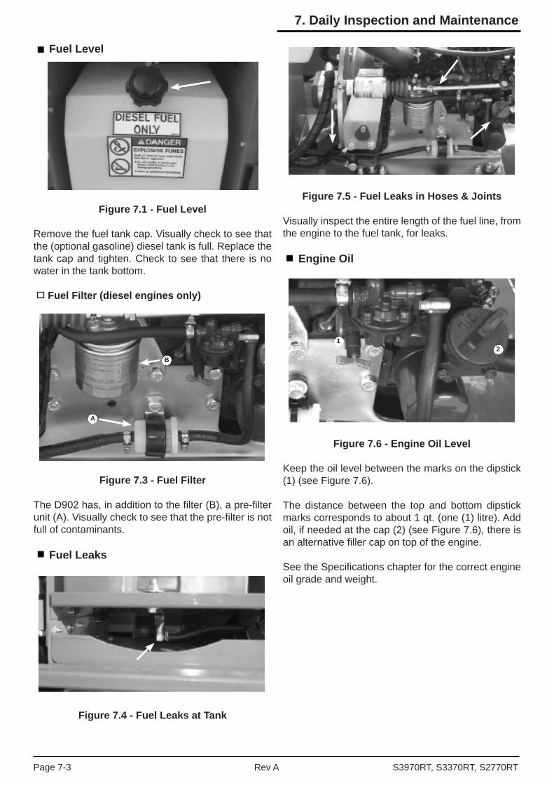
Fuel Level
Figure 7.1 - Fuel Level
Remove the fuel tank cap. Visually check to see that the (optional gasoline) diesel tank is full. Replace the tank cap and tighten. Check to see that there is no water in the tank bottom.
Fuel Filter (diesel engines only)
Figure 7.3 - Fuel Filter
The D902 has, in addition to the fi lter (B), a pre-fi lter unit (A). Visually check to see that the pre-fi lter is not full of contaminants.
Fuel Leaks
Figure 7.4 - Fuel Leaks at Tank
Figure 7.5 - Fuel Leaks in Hoses & Joints
Visually inspect the entire length of the fuel line, from the engine to the fuel tank, for leaks.
Engine Oil
Figure 7.6 - Engine Oil Level
Keep the oil level between the marks on the dipstick (1) (see Figure 7.6).
The distance between the top and bottom dipstick marks corresponds to about 1 qt. (one (1) litre). Add oil, if needed at the cap (2) (see Figure 7.6), there is an alternative fi ller cap on top of the engine.
See the Specifi cations chapter for the correct engine oil grade and weight.
12
B
A
S3970RT, S3370RT, S2770RTRev APage 7-3
7. Daily Inspection and Maintenance

Engine Coolant
Figure 7.7 - Engine Coolant Level
The Kubota engine is liquid cooled. The coolant should be between the FULL level (1) and the LOW level (2) (see fi gure 7.7).
The coolant is half water and half ethylene glycol.
To add coolant:
Turn the engine OFF at the ground control box KEY SWITCH. Remove the cap (3) from the coolant reservoir. Add coolant and replace cap.
Radiator Cap
Figure 7.8 - Radiator Cap
Visually check to see that the cap is in place and tight.
Swinging Gate
Figure 7.9 - Swinging Gate
Inspect the gate to see that it swings freely, latches securely, and is not deformed in any way.
Wiring Harnesses and Connectors
Inspect all the wiring harnesses on the machine for loose connections, broken wires and frayed insula-tion.
Figure 7.10 - Wiring Harnesses and Connectors
Figure 7.11 - Wiring Harnesses in the Scissor Stack
Pay particular attention to the wiring harnesses that are attached to the scissor stack. Note that the wire harness runs beside the main hose bundle.
1
2
3
Page 7-4 Rev A S3970RT, S3370RT, S2770RT
7. Daily Inspection and Maintenance

Battery Terminals
Figure 7.12 - Battery Terminals
Battery Terminals should be clean and free of corro-sion and the battery leads fi rmly attached.
Battery fl uid level
DANGER
Batteries emit hydrogen and oxygen, elements that can combine explosively. Death or serious injury can result from a chemical explosion.
DO NOT smoke or permit open fl ames or sparks when checking batteries.
NoteUnits manufactured in New Zealand are typically fi tted with a “maintenance free” battery.
If your unit is not fi tted with such a battery you will need to do the following.
Remove the caps from the battery and visually check to see that the battery fl uid is 1/4 (6mm) below the bottom of the fi ller neck inside each hole.
Hydraulic Oil Tank
Figure 7.13 - Hydraulic Oil tank
Hydraulic tank cap
Check to see that the cap (1) is in place and is tight (see fi gure 7.13).
Hydraulic oil level
To check the hydraulic oil level:
Completely lower the platform. The hydraulic oil level should be at the full level according to the gauge (2). If necessary add hydraulic oil at the hydraulic oil tank cap. See the specifi cations chapter for types and grades of hydraulic oil.
Hydraulic Oil Leaks
DANGER
Leaking hydraulic oil can cause burns, fi res, falls (slipping), cuts and puncture (if under high pres-sure). Do not tolerate hydraulic oil leaks, they are dangerous.
Do not search for the leaks with your hand, use a piece of cardboard or wood. Hydraulic oil leaks are easily visible and can show up anyplace. Visually inspect the entire machine for hydraulic oil. Check the ground underneath the machine for leaked oil.
Figure 7.14 - Check Fittings at Valve
Check all fi ttings and hoses for leaks. Inspect hoses for signs of damage from chaffi ng or rubbing against protrusions on the chassis or scissor stack.
Figure 7.15 - Check Hydraulic Cylinders
1
2
S3970RT, S3370RT, S2770RTRev APage 7-5
7. Daily Inspection and Maintenance
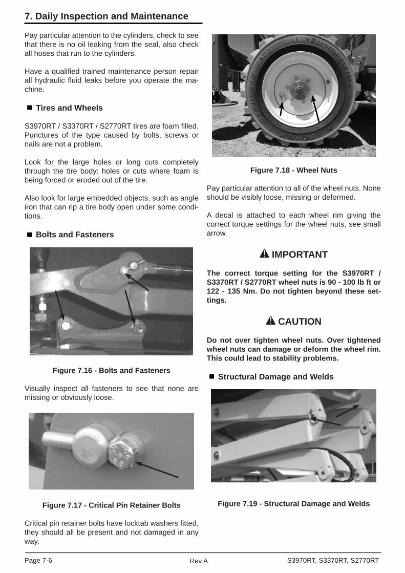
Pay particular attention to the cylinders, check to see that there is no oil leaking from the seal, also check all hoses that run to the cylinders.
Have a qualifi ed trained maintenance person repair all hydraulic fl uid leaks before you operate the ma-chine.
Tires and Wheels
S3970RT / S3370RT / S2770RT tires are foam fi lled. Punctures of the type caused by bolts, screws or nails are not a problem.
Look for the large holes or long cuts completely through the tire body: holes or cuts where foam is being forced or eroded out of the tire.
Also look for large embedded objects, such as angle iron that can rip a tire body open under some condi-tions.
Bolts and Fasteners
Figure 7.16 - Bolts and Fasteners
Visually inspect all fasteners to see that none are missing or obviously loose.
Figure 7.17 - Critical Pin Retainer Bolts
Critical pin retainer bolts have locktab washers fi tted, they should all be present and not damaged in any way.
Figure 7.18 - Wheel Nuts
Pay particular attention to all of the wheel nuts. None should be visibly loose, missing or deformed.
A decal is attached to each wheel rim giving the correct torque settings for the wheel nuts, see small arrow.
IMPORTANT
The correct torque setting for the S3970RT / S3370RT / S2770RT wheel nuts is 90 - 100 lb ft or 122 - 135 Nm. Do not tighten beyond these set-tings.
CAUTION
Do not over tighten wheel nuts. Over tightened wheel nuts can damage or deform the wheel rim. This could lead to stability problems.
Structural Damage and Welds
Figure 7.19 - Structural Damage and Welds
Page 7-6 Rev A S3970RT, S3370RT, S2770RT
7. Daily Inspection and Maintenance
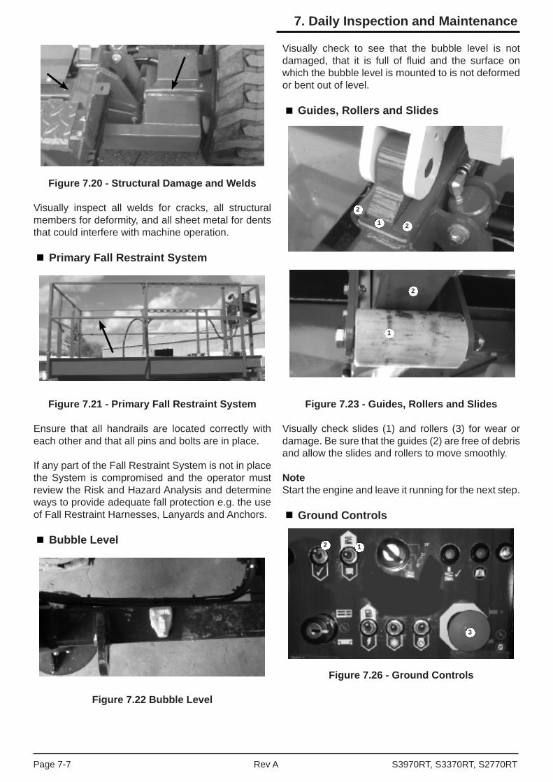
Figure 7.20 - Structural Damage and Welds
Visually inspect all welds for cracks, all structural members for deformity, and all sheet metal for dents that could interfere with machine operation.
Primary Fall Restraint System
Figure 7.21 - Primary Fall Restraint System
Ensure that all handrails are located correctly with each other and that all pins and bolts are in place.
If any part of the Fall Restraint System is not in place the System is compromised and the operator must review the Risk and Hazard Analysis and determine ways to provide adequate fall protection e.g. the use of Fall Restraint Harnesses, Lanyards and Anchors.
Bubble Level
Figure 7.22 Bubble Level
Visually check to see that the bubble level is not damaged, that it is full of fl uid and the surface on which the bubble level is mounted to is not deformed or bent out of level.
Guides, Rollers and Slides
Figure 7.23 - Guides, Rollers and Slides
Visually check slides (1) and rollers (3) for wear or damage. Be sure that the guides (2) are free of debris and allow the slides and rollers to move smoothly.
NoteStart the engine and leave it running for the next step.
Ground Controls
Figure 7.26 - Ground Controls
1
2
2
1
2
2 1
3
S3970RT, S3370RT, S2770RTRev APage 7-7
7. Daily Inspection and Maintenance
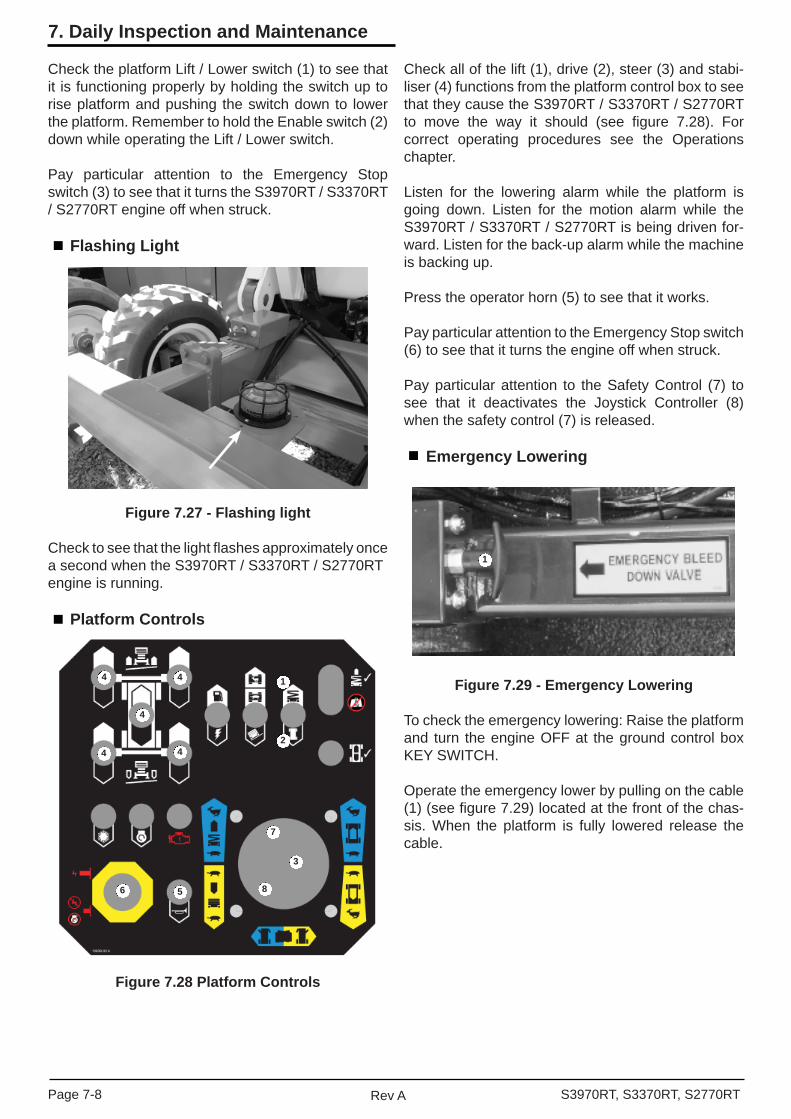
Check the platform Lift / Lower switch (1) to see that it is functioning properly by holding the switch up to rise platform and pushing the switch down to lower the platform. Remember to hold the Enable switch (2) down while operating the Lift / Lower switch.
Pay particular attention to the Emergency Stop switch (3) to see that it turns the S3970RT / S3370RT / S2770RT engine off when struck.
Flashing Light
Figure 7.27 - Flashing light
Check to see that the light fl ashes approximately once a second when the S3970RT / S3370RT / S2770RTengine is running.
Platform Controls
Figure 7.28 Platform Controls
Check all of the lift (1), drive (2), steer (3) and stabi-liser (4) functions from the platform control box to see that they cause the S3970RT / S3370RT / S2770RT to move the way it should (see fi gure 7.28). For correct operating procedures see the Operations chapter.
Listen for the lowering alarm while the platform is going down. Listen for the motion alarm while the S3970RT / S3370RT / S2770RT is being driven for-ward. Listen for the back-up alarm while the machine is backing up.
Press the operator horn (5) to see that it works.
Pay particular attention to the Emergency Stop switch (6) to see that it turns the engine off when struck.
Pay particular attention to the Safety Control (7) to see that it deactivates the Joystick Controller (8) when the safety control (7) is released.
Emergency Lowering
Figure 7.29 - Emergency Lowering
To check the emergency lowering: Raise the platform and turn the engine OFF at the ground control box KEY SWITCH.
Operate the emergency lower by pulling on the cable (1) (see fi gure 7.29) located at the front of the chas-sis. When the platform is fully lowered release the cable.
4
4
4
4
4
1
2
7
3
86 5
1
Page 7-8 Rev A S3970RT, S3370RT, S2770RT
7. Daily Inspection and Maintenance

RCD / ELCB (Option)
Figure 7.30 - RCD /ELCB
The RCD (Residual Current Device) is located at the ground and will protect against short circuits to earth. When there is a short circuit the RCD will shut down the 230V AC power to the platform outlet.
To reset the outlet disconnect the power tool lead from the platform box and reset the RCD at the ground.
If the problem persists call a trained service techni-cian.
Safety Prop
Figure 7.31 - Safety Prop
Inspect the safety prop(s) to see that it is present and moves freely.
Fall Restraint Lanyard Anchor Points (Option)
Check all three (3) of the Fall Restraint anchorages on the fl oor of the platform for the S3970RT / S3370RT /S2770RT to see that they are present, not deformed, that they move freely and that they are securely at-tached to the platform.
Non-Slip Tread Grip
Figure 7.32 - Non Slip Grip Strip
Check that the non slip protective strip is in place and in good condition.
Wrist Support
Figure 7.33 - Wrist Support
Check the condition of the rubber on the upper control box wrist support. Replace it if it is worn or damaged.
Operator Manual
Figure 7.34 - Operator Manual Holder
Check that the Operator Manual is in the holder.
S3970RT, S3370RT, S2770RTRev APage 7-9
7. Daily Inspection and Maintenance
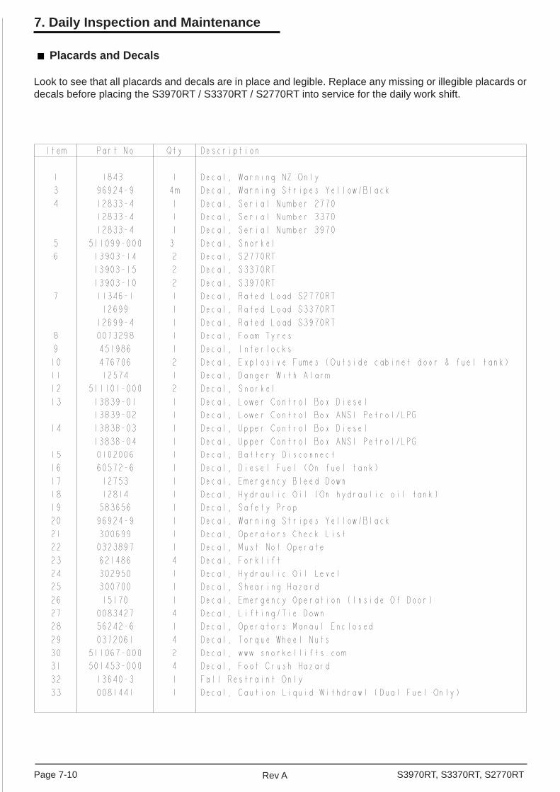
Placards and Decals
Look to see that all placards and decals are in place and legible. Replace any missing or illegible placards or decals before placing the S3970RT / S3370RT / S2770RT into service for the daily work shift.
Page 7-10 Rev A S3970RT, S3370RT, S2770RT
7. Daily Inspection and Maintenance

5
1218
19
24
RIGHT HAND SIDE
3
30
20 20
31
2326
22
25
23
29 29
LEFT HAND SIDE
16
10
10
20 20
30 6
3
23 23
17
12
2929
REAR END
27
111
1520
9
8
28
20
27
13
214
7
14
3
5
5
3
20 20
27
FRONT END
27
X All 4 Stabilisers
6Placards and decals drawing
S3970RT, S3370RT, S2770RTRev APage 7-11
7. Daily Inspection and Maintenance

Page 7-12 Rev A S3970RT, S3370RT, S2770RT
7. Daily Inspection and Maintenance

Figure 8.1 - Emergency Stop Switch atGround Control Box
Ground control box Emergency Stop switch location.
Figure 8.2 - Emergency Stop switch atPlatform Control Box
Platform control box Emergency Stop switch location.
To stop the machine from the platform control box, push the Emergency Stop switch, at any time and the entire machine stops and nothing moves.
NoteIn order for the Emergency Stop switch to have an ef-fect at the platform, the platform / ground key selector switch must be set on platform.
NoteFor a complete discussion of the Emergency Stop switches, see Controls chapter, and Emergency Operation chapter 1, in this manual.
Operation Considerations
To use this chapter, fi rst decide whether you will be starting and operating the S3970RT / S3370RT / S2770RT from the ground control box or the platform control box.
Begin at the section entitled Operating From The Ground Control Box if you intend to run the S3970RT / S3370RT / S2770RT from the ground control box.
Operating Procedures
This chapter explains how to start and run the machine. Read and understand all the previous chapters before you begin to operate the machine.
Control Stations
The machine can be started and operated from the ground control box or the platform control box.
IMPORTANT
The ground control box can override the platform control box at any time. If a person operating the machine at any time becomes incapacitated, a person on the ground can always take over the machine control.
DANGER
The S3970RT / S3370RT / S2770RT is notelectrically insulated
Death or serious injury to operating person-nel can occur if the machine should come into contact with energised electrical wires during operation.
DO NOT attempt to operate the S3970RT / S3370RT / S2770RT ground controls if the platform, scis-sor assembly or any other conducting part of the machine is in contact with energised electrical wires or if there is an immediate danger of such contact.
NoteSee the Electrical Hazard section, in this manual for a complete explanation of the hazards concerning electricity.
Emergency Stopping
WARNING
When the platform / ground key selector switch is set to GROUND the entire platform control box is inoperative including the Emergency Stop.
To stop the machine from the ground control box, push the Emergency Stop switch, at any time and the entire machine stops and nothing moves.
Push the emergency stop button inward when the upper or lower controls are not in use to protect against un-intentional operation.
S3970RT, S3370RT, S2770RTRev APage 8-1
8. Operation
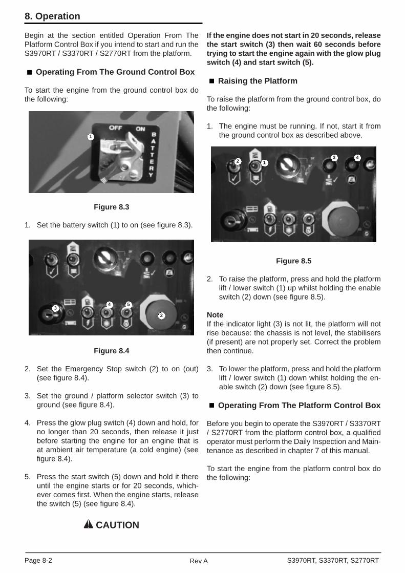
Begin at the section entitled Operation From The Platform Control Box if you intend to start and run the S3970RT / S3370RT / S2770RT from the platform.
Operating From The Ground Control Box
To start the engine from the ground control box do the following:
Figure 8.3
1. Set the battery switch (1) to on (see fi gure 8.3).
Figure 8.4
2. Set the Emergency Stop switch (2) to on (out) (see fi gure 8.4).
3. Set the ground / platform selector switch (3) to ground (see fi gure 8.4).
4. Press the glow plug switch (4) down and hold, for no longer than 20 seconds, then release it just before starting the engine for an engine that is at ambient air temperature (a cold engine) (see fi gure 8.4).
5. Press the start switch (5) down and hold it there until the engine starts or for 20 seconds, which-ever comes fi rst. When the engine starts, release the switch (5) (see fi gure 8.4).
CAUTION
If the engine does not start in 20 seconds, release the start switch (3) then wait 60 seconds before trying to start the engine again with the glow plug switch (4) and start switch (5).
Raising the Platform
To raise the platform from the ground control box, do the following:
1. The engine must be running. If not, start it from the ground control box as described above.
Figure 8.5
2. To raise the platform, press and hold the platform lift / lower switch (1) up whilst holding the enable switch (2) down (see fi gure 8.5).
NoteIf the indicator light (3) is not lit, the platform will not rise because: the chassis is not level, the stabilisers (if present) are not properly set. Correct the problem then continue.
3. To lower the platform, press and hold the platform lift / lower switch (1) down whilst holding the en-able switch (2) down (see fi gure 8.5).
Operating From The Platform Control Box
Before you begin to operate the S3970RT / S3370RT / S2770RT from the platform control box, a qualifi ed operator must perform the Daily Inspection and Main-tenance as described in chapter 7 of this manual.
To start the engine from the platform control box do the following:
1
34 5
2
2 13 4
Page 8-2 Rev A S3970RT, S3370RT, S2770RT
8. Operation

Figure 8.6
1. Set the battery switch (1) to on (see fi gure 8.6).
Figure 8.7
2. Set the Emergency Stop switch (2) to on (out) (see fi gure 8.7).
3. Set the ground / platform selector switch (3) to platform (up) (see fi gure 8.7)
4. Enter the platform and close the gate.
Figure 8.8
5. Pull the Emergency Stop switch (4) outward (on) (see fi gure 8.8).
6. Press the glow plug switch (5) down and hold, for no longer than 20 seconds, then release it just before starting the engine for an engine that is at ambient air temperature (a cold engine) (see fi gure 8.8).
7. Press and hold the start switch (6) down until the engine starts or for 20 seconds, whichever comes fi rst. When the engine starts release the start switch (6) (see fi gure 8.8).
CAUTION
If the engine does not start in 20 seconds, release the start switch (6) then wait 60 seconds before trying to start the engine again with glow plug (5) and start switches (6).
1
2
3
4
5 6
S3970RT, S3370RT, S2770RTRev APage 8-3
8. Operation

Driving
1. The engine should be running. If not, start it from the platform control box as described previously.
Figure 8.9
2. Set the speed switch (1) to turtle (slow) (see fi gure 8.9) if you are going to be driving close to other objects or need to move the S3970RT / S3370RT / S2770RT very slowly for other reasons.
NoteSetting the speed to rabbit doubles the travel speed. (See the specifi cations chapter for speeds or differentmodels).
3. Set the lift / drive switch (2) to drive (see fi gure 8.9).
WARNING
The S3970RT / S3370RT / S2770RT is about to move. If you have to make an emergency stop, release the joystick controller (3) and sharply strike the Emergency Stop switch (4) straight in.
To make a normal stop, slowly move the joystick controller (3) (see fi gure 8.9).
4. Squeeze and hold the safety control (5) against the joystick controller (3) (see fi gure 8.9).
5. Push the joystick controller (3) slowly forward or pull it slowly backward, depending on which way you want to go. The further you move the joystick the faster the machine goes.
6. To make a right or left turn, press and hold the steering rocker switch (6) on top of the joystick controller (3) (see fi gure 8.9).
4 3
65
21
NoteWhen you release the steering rocker switch (6) the steering wheels remain pointed in the direction you left them. They do not return to straight ahead the way automobile wheels do. You will have to press the opposite side of the steering rocker switch (6) to re-turn to straight line travel. In tight spots you should stop the S3970RT / S3370RT / S2770RT, turn the wheels the direction you want to go, then, after you have aimed the steering wheels, squeeze the safe-ty controller (5) and move the joystick controller (3) slowly forward or backward.
Variable maximum drive speed
The machine features a variable maximum drive speed with height. As the elevation gets higher the drive speed reduces.
Stowed, and up to the elevation height, the maxi-mum drive speed is the stowed drive speed. Above the elevation height maximum drive speed reduces as the height increases. At maximum elevation the maximum drive speed is the creep speed. At heights above elevation but less then full height this gives a signifi cant increase in the maximum drive speed and corresponding increases in productivity (see exampletable below).
Ramp off
The controls feature a small amount of “ramp off”. If the trigger safety control is released or the joystick controller is abruptly moved to the center the drive speed will be reduced over a small period of time. This makes deceleration much smoother. There is a small amount of overrun of the machine. Take care to allow suffi cient stopping distance from objects.
Page 8-4 Rev A S3970RT, S3370RT, S2770RT
8. Operation
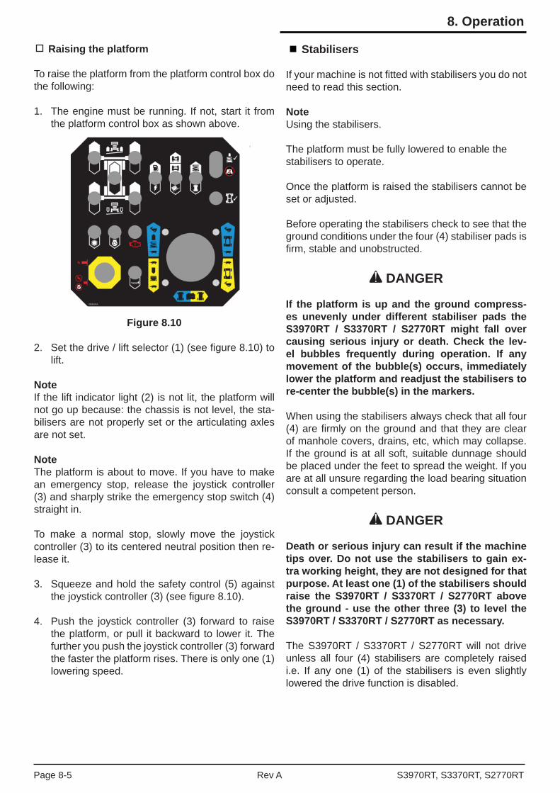
Raising the platform
To raise the platform from the platform control box do the following:
1. The engine must be running. If not, start it from the platform control box as shown above.
Figure 8.10
2. Set the drive / lift selector (1) (see fi gure 8.10) to lift.
NoteIf the lift indicator light (2) is not lit, the platform will not go up because: the chassis is not level, the sta-bilisers are not properly set or the articulating axles are not set.
NoteThe platform is about to move. If you have to make an emergency stop, release the joystick controller (3) and sharply strike the emergency stop switch (4) straight in.
To make a normal stop, slowly move the joystick controller (3) to its centered neutral position then re-lease it.
3. Squeeze and hold the safety control (5) against the joystick controller (3) (see fi gure 8.10).
4. Push the joystick controller (3) forward to raise the platform, or pull it backward to lower it. The further you push the joystick controller (3) forward the faster the platform rises. There is only one (1) lowering speed.
Stabilisers
If your machine is not fi tted with stabilisers you do not need to read this section.
NoteUsing the stabilisers.
The platform must be fully lowered to enable thestabilisers to operate.
Once the platform is raised the stabilisers cannot be set or adjusted.
Before operating the stabilisers check to see that the ground conditions under the four (4) stabiliser pads is fi rm, stable and unobstructed.
DANGER
If the platform is up and the ground compress-es unevenly under different stabiliser pads the S3970RT / S3370RT / S2770RT might fall over causing serious injury or death. Check the lev-el bubbles frequently during operation. If any movement of the bubble(s) occurs, immediately lower the platform and readjust the stabilisers to re-center the bubble(s) in the markers.
When using the stabilisers always check that all four (4) are fi rmly on the ground and that they are clear of manhole covers, drains, etc, which may collapse. If the ground is at all soft, suitable dunnage should be placed under the feet to spread the weight. If you are at all unsure regarding the load bearing situation consult a competent person.
DANGER
Death or serious injury can result if the machine tips over. Do not use the stabilisers to gain ex-tra working height, they are not designed for that purpose. At least one (1) of the stabilisers should raise the S3970RT / S3370RT / S2770RT above the ground - use the other three (3) to level the S3970RT / S3370RT / S2770RT as necessary.
The S3970RT / S3370RT / S2770RT will not drive unless all four (4) stabilisers are completely raised i.e. If any one (1) of the stabilisers is even slightly lowered the drive function is disabled.
S3970RT, S3370RT, S2770RTRev APage 8-5
8. Operation
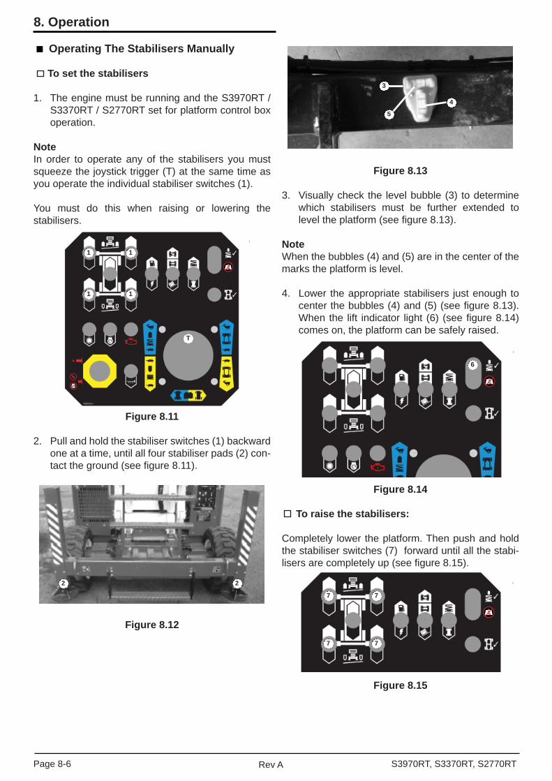
Operating The Stabilisers Manually
To set the stabilisers
1. The engine must be running and the S3970RT / S3370RT / S2770RT set for platform control box operation.
NoteIn order to operate any of the stabilisers you must squeeze the joystick trigger (T) at the same time as you operate the individual stabiliser switches (1).
You must do this when raising or lowering the stabilisers.
Figure 8.11
2. Pull and hold the stabiliser switches (1) backward one at a time, until all four stabiliser pads (2) con-tact the ground (see fi gure 8.11).
Figure 8.12
Figure 8.13
3. Visually check the level bubble (3) to determine which stabilisers must be further extended to level the platform (see fi gure 8.13).
NoteWhen the bubbles (4) and (5) are in the center of the marks the platform is level.
4. Lower the appropriate stabilisers just enough to center the bubbles (4) and (5) (see fi gure 8.13). When the lift indicator light (6) (see fi gure 8.14) comes on, the platform can be safely raised.
Figure 8.14
To raise the stabilisers:
Completely lower the platform. Then push and hold the stabiliser switches (7) forward until all the stabi-lisers are completely up (see fi gure 8.15).
Figure 8.15
1
11
1
T
22
77
77
6
5
3
4
Page 8-6 Rev A S3970RT, S3370RT, S2770RT
8. Operation

Operating the Auto Level System
Setting the stabilisers automatically
1. The engine must be running and the S3970RT / S3370RT / S2770RT set for platform control box operation.
NoteIn order to operate the Auto Level stabiliser switch (1) you must squeeze the joystick trigger (T) at the sametime as you operate the Auto Level switch.
You must do this when raising or lowering thestabilisers.
Figure 8.16
2. Press and hold the switch (1) down to the Auto Level position until all movement stops of the lift enable light (2) illuminates. The S3970RT / S3370RT / S2770RT will attempt to automatically level itself.
3. The lift enable light (2) will illuminate if all 4 feet are in contact with the ground and the machine is level.
4. If a stabiliser foot will not go down suffi ciently to make contact with the ground it is possible that the cylinder has reached the end of its stroke. Retract all stabilisers and put suitable dunnage under the feet that did not touch the ground and repeat step 2.
NoteManual or auto leveling is possible any time that sta-biliser movement is allowed. For example, the ma-chine can be manually leveled part way and then auto leveled without the necessity of retracting the stabilisers between the two (2) operations.
Raising the stabilisers automatically
1. Completely lower the platform.
2. Press and hold the switch (1) up to the Auto Stow position. The stabilisers will raise to the stowed position.
The Risks of Operating Scissor Lifts on Outriggers on Ramps and Slopes
There is a risk of scissor lifts with outriggers sliding down ramps, driveways, underground car park entry ramps and outdoor slopes. The contributing factors include newly painted ramps, icy, wet oil and sand covered ramps, grassy and loose surface slopes.
This can occur when the platform is fully lowered or when elevated.
Do not attempt to pack wheel chocks or timber under the outrigger footplates or the tyres.
The outrigger foot plates must be lowered only onto a fi rm surface that can support the load of the S3970RT / S3370RT / S2770RT and its rated capacity.
Figure 8.17
The positioning of outrigger footplates on stepped level surfaces (capable of supporting the S3970RT / S3370RT / S2770RT) is acceptable (see fi gure 8.17 & 8.18)
1
2
T
S3970RT, S3370RT, S2770RTRev APage 8-7
8. Operation

Figure 8.18
The positioning of outrigger footplates on ramps and slopes creates the risk of the machine sliding down the ramp or slope (see fi gure 8.19 & 8.20).
Figure 8.19
Figure 8.20
A competent person shall assess slope and surface conditions before setting up the machine on a slope.
Extending The Multi-Position Platform
Figure 8.21.
The multi-position extendable platform (see fi gure 8.21) can be securely locked into different positions. To move it from one position to the other, do the following:
1. Stand on the non-extendable part of the platform and face the front of the machine.
WARNING
The distribution of the rated work load changes when the extendable platform is extended. Read the decal on the toe board at the front of the plat-form or at the entrance to the platform for safe weight distribution.
2. Lift up the deck extension handles (one for each side of the deck) (1) to unlock the deck (see fi gure 8.21).
3. Push or pull the deck extension handles to move the platform to the desired position.
4. Lower the deck extension handles and allow the lock (2) to locate (see fi gure 8.21).
21
Page 8-8 Rev A S3970RT, S3370RT, S2770RT
8. Operation

Emergency Operation Procedures
The following procedures are emergency procedures only. Do not use them for normal operation. Their purpose is to get the platform and operator safely to the ground when the S3970RT / S3370RT / S2770RT will not start or some other problem keeps the plat-form from lowering in the normal way, or to move the S3970RT / S3370RT / S2770RT a short distance to a safe place when the motor will not start.
There are three (3) forms of emergency operation for the S3970RT / S3370RT / S2770RT. Emergency stop, emergency bleed down and pushing.
Each is covered in a separate section below:
Emergency Stop
There are two (2) Emergency Stop switches on the machine.
Figure 9.1 - Platform Control Box EmergencyStop Switch
Figure 9.2 - Ground Control Box EmergencyStop Switch
WARNING
When the platform / ground key selector switch is set to ground the entire platform control box is inoperative including the emergency stop.
Push either emergency stop switch (see fi gures 9.1 & 9.2) at any time, and the entire machine stops, the engine turns off and nothing moves.
NoteIn order for the emergency stop switch to have an effect at the platform, the platform / ground selector switch must be set on platform.
Functionally, the emergency stop switches do the same thing as turning the main power switch to off. The emergency stop switches are designed to be easier to fi nd and faster to use than key switches.
To reset the emergency stop at the platform control box or the ground control box, pull it and it will pop out (on). The S3970RT / S3370RT / S2770RT engine can then be restarted in the normal way.
Emergency Bleed Down
The S3970RT / S3370RT / S2770RT platform can be lowered from the platform control box anytime there is electricity to the platform control box the S3970RT / S3370RT / S2770RT engine does not have to be running.
If you are working from the platform and the engine dies and cannot be restarted, do the following:
Figure 9.3
1. Check to be sure the emergency stop switch (1) is pulled out (on) (see fi gures 9.1 and 9.3).
2. Set the selector switch (2) (see fi gure 9.3) to the platform function (up).
1 4
3
2
S3970RT, S3370RT, S2770RTRev APage 9-1
9. Emergency Operation

3. Squeeze the safety control (3) and pull the joy-stick controller (4) (see fi gure 9.3) backward. The platform should lower. If it does not lower, call for help from someone on the ground.
The person on the ground should do the following:
Figure 9.4
• Check to be sure the battery switch (5) is on (see fi gure 9.4).
Figure 9.5
• Check to be sure the emergency stop switch (6) (see fi gure 9.5) is on (out).
• Check to be sure the selector switch (7) is set to platform (up) (see fi gure 9.5).
• If the battery switch (5), emergency stop (6) and selector switch (7) are all set correctly, and the engine will not start from the platform control box, set the selector switch (7) to ground (down) and try to lower the platform from the ground control box.
DANGER
Pinching and crushing hazard. At the next step the platform will come down and the scissor arms will close. Keep all body parts out of the scissor arms and out from under the platform.
5
7
6
8
Figure 9.6 - Manual Bleed Down Control
• If the platform will not lower, the person on the ground will need to use the manual bleed down (8) (see fi gure 9.6) located at the front of the chassis. To lower the platform pull on the cable (8) until the platform if fully lowered.
NoteIf the platform does not come down, refer the problemto a qualifi ed trained service technician.
Pushing / Towing
When stowed the machine can be safely pushed or towed to level fi rm surfaces. To do so:
Figure 9.7
1. Turn the battery switch (1) to off (see fi gure 9.7).
Figure 9.8
1
3
2
Page 9-2 Rev A S3970RT, S3370RT, S2770RT
9. Emergency Operation
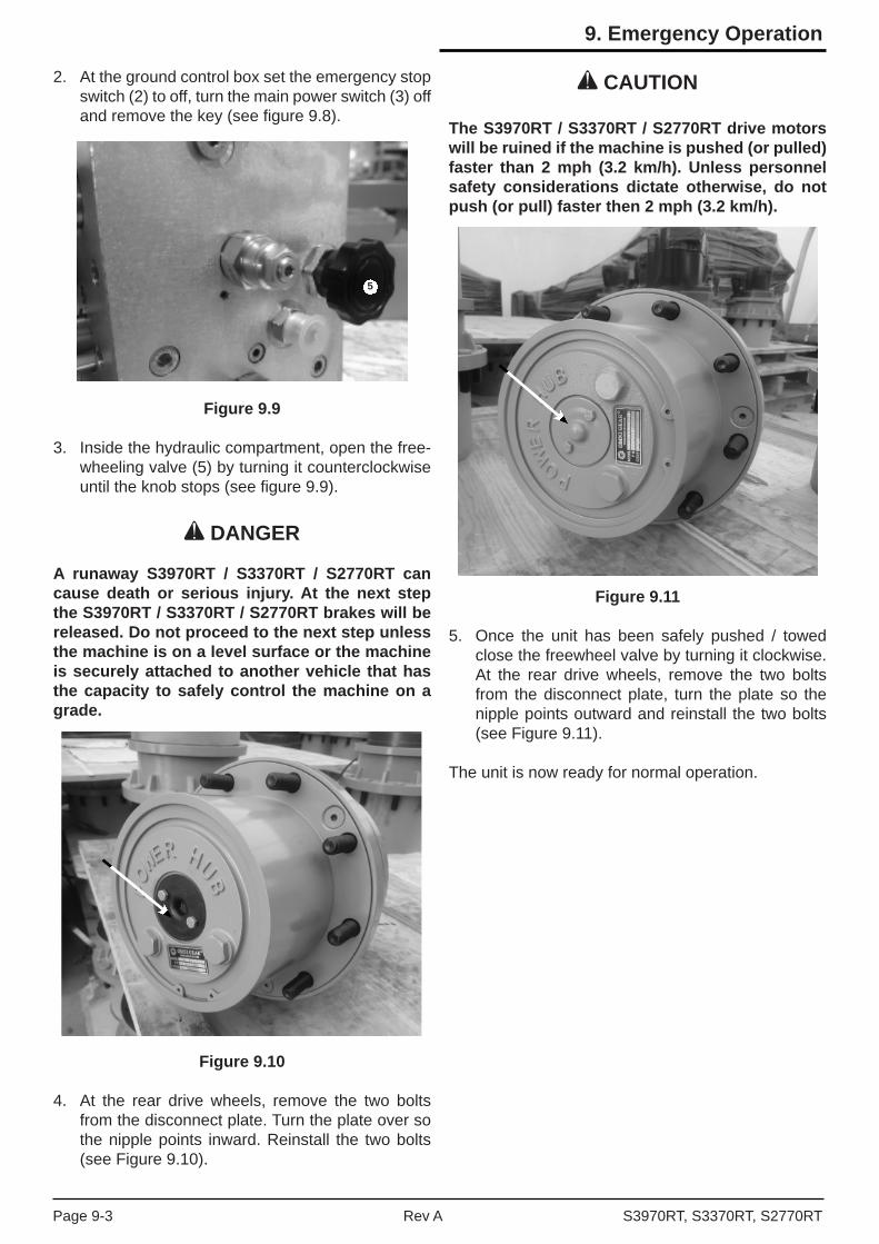
2. At the ground control box set the emergency stop switch (2) to off, turn the main power switch (3) off and remove the key (see fi gure 9.8).
Figure 9.9
3. Inside the hydraulic compartment, open the free-wheeling valve (5) by turning it counterclockwise until the knob stops (see fi gure 9.9).
DANGER
A runaway S3970RT / S3370RT / S2770RT can cause death or serious injury. At the next step the S3970RT / S3370RT / S2770RT brakes will be released. Do not proceed to the next step unless the machine is on a level surface or the machine is securely attached to another vehicle that has the capacity to safely control the machine on a grade.
Figure 9.10
4. At the rear drive wheels, remove the two bolts from the disconnect plate. Turn the plate over so the nipple points inward. Reinstall the two bolts (see Figure 9.10).
CAUTION
The S3970RT / S3370RT / S2770RT drive motors will be ruined if the machine is pushed (or pulled) faster than 2 mph (3.2 km/h). Unless personnel safety considerations dictate otherwise, do not push (or pull) faster then 2 mph (3.2 km/h).
Figure 9.11
5. Once the unit has been safely pushed / towed close the freewheel valve by turning it clockwise. At the rear drive wheels, remove the two bolts from the disconnect plate, turn the plate so the nipple points outward and reinstall the two bolts (see Figure 9.11).
The unit is now ready for normal operation.
5
S3970RT, S3370RT, S2770RTRev APage 9-3
9. Emergency Operation

Page 9-4 Rev A S3970RT, S3370RT, S2770RT
9. Emergency Operation
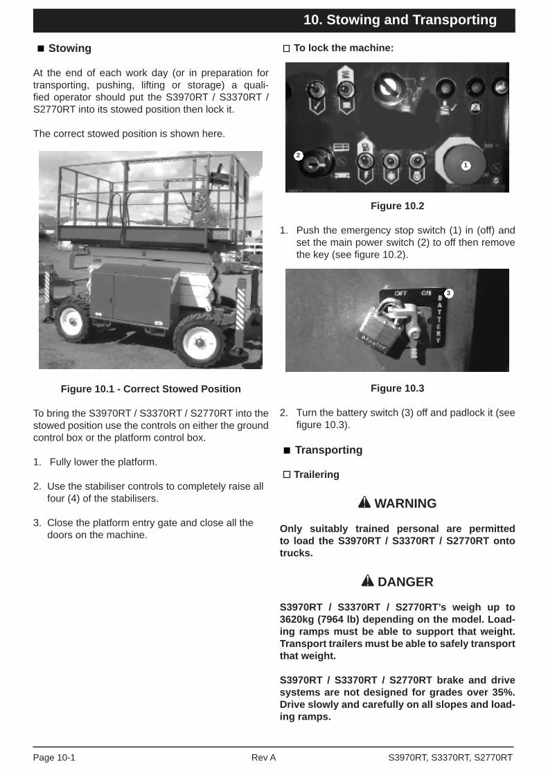
Stowing
At the end of each work day (or in preparation for transporting, pushing, lifting or storage) a quali-fi ed operator should put the S3970RT / S3370RT / S2770RT into its stowed position then lock it.
The correct stowed position is shown here.
Figure 10.1 - Correct Stowed Position
To bring the S3970RT / S3370RT / S2770RT into the stowed position use the controls on either the ground control box or the platform control box.
1. Fully lower the platform.
2. Use the stabiliser controls to completely raise all four (4) of the stabilisers.
3. Close the platform entry gate and close all the doors on the machine.
To lock the machine:
Figure 10.2
1. Push the emergency stop switch (1) in (off) and set the main power switch (2) to off then remove the key (see fi gure 10.2).
Figure 10.3
2. Turn the battery switch (3) off and padlock it (see fi gure 10.3).
Transporting
Trailering
WARNING
Only suitably trained personal are permitted to load the S3970RT / S3370RT / S2770RT onto trucks.
DANGER
S3970RT / S3370RT / S2770RT’s weigh up to 3620kg (7964 lb) depending on the model. Load-ing ramps must be able to support that weight. Transport trailers must be able to safely transport that weight.
S3970RT / S3370RT / S2770RT brake and drive systems are not designed for grades over 35%. Drive slowly and carefully on all slopes and load-ing ramps.
3
21
S3970RT, S3370RT, S2770RTRev APage 10-1
10. Stowing and Transporting

To safely drive a machine onto a transport trailer:
1. Visually inspect the alignment of the loading ramp and the truck or trailer. They should both be on the same straight line.
2. Set the S3970RT / S3370RT / S2770RT ground control box for platform operation.
3. Enter the platform and close the safety gate.
4. Use the platform controls to bring the machine into the stowed position at the foot of the loading ramp with the steering wheels nearest the ramps.
5. Visually check (from the platform) to be sure the S3970RT / S3370RT / S2770RT is aligned with the ramp and the ramp is still aligned with the truck or trailer. All should be in a straight line.
DANGER
Death or serious injury can result from losing control of the machine during loading or unload-ing. Always drive up or down a grade with the speed switch set to turtle (slow).
Figure 10.4
6. Use the joystick controller (3) to slowly drive the S3970RT / S3370RT / S2770RT straight onto the ramp (4) and trailer (5) (see fi gure 10.4).
7. When the S3970RT / S3370RT / S2770RT is in place on the trailer, push the emergency stop switch (6) in (off) at the platform control box.
8. Chock the S3970RT / S3370RT / S2770RT wheels.
Securing to a transport vehicle
This procedure assumes that you have just fi nished the previous section and that the wheels are chocked.
Figure 10.5
1. Push the emergency stop switch (1) in (off) and set the main power switch (2) to off then remove the key (see fi gure 10.5).
Figure 10.6
2. Set the battery switch (3) (see fi gure 10.6) to off and padlock it.
Figure 10.8 - Tie-down Lugs
Always attach chains to the front and back tie-down lugs (4) (see fi gures 10.8 & 10.9).
63
54
21
3
4 4
Page 10-2 Rev A S3970RT, S3370RT, S2770RT
10. Stowing and Transporting

Figure 10.9 - Tie-down Lugs
Chocks may be removed at this time, though it is a good idea to leave them in place.
Reverse the above procedure after transporting.
Towing
Do not tow the machine. The S3970RT / S3370RT / S2770RT hydraulic drive motors will be permanently damaged, and rendered useless, by towing speeds.
Lifting
WARNING
Lifting the S3970RT / S3370RT / S2770RT must only be performed by a competent person.
The competent person must refer to the machine specifi cations in the manual and on the serial plate.
The machine must only be lifted by the lifting lugs. Lifting the machine requires the use of suitable rated and approved lifting equipment.
The competent person shall plan the lift including selecting the appropriate equipment. It is suggested that spreader bars or similar be used to avoid dam-age to the S3970RT / S3370RT / S2770RT.
Figure 10.10 - Lifting
Pushing
The machine can be safely pushed on level, fi rm surfaces. The procedure for pushing is located in the emergency operation chapter.
Winching Procedure
1. Locate transport vehicle so that the S3970RT / S3370RT / S2770RT will not roll forward after be-ing loaded.
2. Fully lower platform and retract extension deck.
3. Be sure the machine is centered with the loading ramps and carrier vehicle bed, and that the steer-ing wheels are straight.
4. Attach the winch at the tie down lugs on the front (steer) end of the chassis.
5. Disengage parking brakes and open free-wheel-ing valve to prevent damage to the hydraulic motors. Refer to procedures outlined for pushing in the emergency operation chapter 9.
6. Winch machine onto transport vehicle.
7. Close free-wheeling valve and reset parking brakes.
8. Reset the hydraulic system by reversing these procedures.
Long Term Storage
When intending to store the S3970RT / S3370RT / S2770RT for more then 90 days without use, place the machine in covered storage, ensure the machine is isolated i.e. key removed, battery disconnect off and padlocked.
When returning a machine to service from a sus-tained period of disuse (over 90 days) perform the 90 day inspection. Also replace the engine oil and hydraulic oil and all fi lters.
4
S3970RT, S3370RT, S2770RTRev APage 10-3
10. Stowing and Transporting

Page 10-4 Rev A S3970RT, S3370RT, S2770RT
10. Stowing and Transporting

This chapter lists and explains the options available for the machine.
Bi-Energy Option
This consists of a combination of both a diesel engine and a 24V DC motor to give a Bi-Energy option.
Specifi cally, a 24V DC motor is mounted in the control cabinet. This provides an alternative power source to the diesel engine.
The DC motor is powered by four (4) “Deep Cycle Traction Batteries” and has an automatic battery charger that is mounted in the control cabinet.
DC motor
The DC motor located in the control cabinet (see fi gure 11.1).
Figure 11.1 - DC Motor
DC Motor Operation
A diesel / electric switch, on the lower control box (see fi gure 11.2) is used to select either the diesel engine or the DC motor.
If the diesel engine (switch up) is selected the DC motor will not function and if the DC motor (switch down) is selected the diesel motor will not run.
Figure 11.2 - Diesel / Electric Selection Switch
After selecting the DC mode turn the selector switch to the platform position (see fi gure 11.3).
Figure 11.3 - Selector Switch
When entering the platform turn the fuel switch to the electric position (down) at the platform control box (see fi gure 11.4).
Figure 11.4 - Fuel Switch, Platform
Once the DC mode is selected the motor will then power all of the functions including the stabilisers in the normal manner. The only difference is that the DC motor will only run when a function is selected e.g. raising the stack.
Master battery isolater switches
There are two (2) master battery isolator switches mounted at the end of the control cabinet (see fi gure 11.5).
When the machine is not being used and is stowed both of these battery isolator switches should be turned to the “off” position.
When operating with the diesel motor the 24V DC battery isolator switch should be switched to the “off” position.
When operating the 24V DC motor the diesel battery isolator switch should be turned to the “off” position.
S3970RT, S3370RT, S2770RTRev APage 11-1
11. Options

Batteries
Since the Bi-Energy S3970RT / S3370RT / S2770RT is powered by “Deep Cycle Traction Batteries” partic-ular attention should be paid to the batteries on board charger to ensure proper operation.
The batteries are enclosed in a cabinet mounted at the front of the machine.
Unscrew the knurled knobs at each end of the cabi-net to remove the lid to gain access to the batteries (see fi gure 11.5).
Figure 11.5 - DC Motor Batteries
IMPORTANT
The cabinet lid must be open whilst charging to allow gasses to escape.
DANGER
Lead-acid batteries contain sulphuric acid which will damage eyes or skin on contact. When working around batteries ALWAYS wear a face shield to avoid acid in the eyes. If acid contacts eyes, fl ush immediately with clear water and get medical attention.
Wear rubber gloves and protective clothing to keep acid off the skin, if acid contacts the skin, wash it off immediately with clear water.
Lead-acid batteries produce fl ammable and explosive gasses. NEVER allow smoking, fl ames or sparks around batteries.
Battery Charger
The Bi-Energy S3970RT / S3370RT / S2770RT is fi tted with an onboard automatic battery charger (see fi gure 11.6). The charger will completely recharge the batteries and automatically turn off after the cycle is completed.
Figure 11.6 - On-Board Battery Charger
The battery charger is fi tted with an ‘interlock”. This means that during the charging cycle all functions on the machine are inoperative and will remain so until the charger unit is switched off.
The charging cycle may last from 1 to 12 hours depending on that state of the batteries.
If the charging cycle should exceed 16 hours (indicat-ing a fault) the charger will automatically shut down and the batteries should be checked.
The inlet for connections of mains power to the char-ger is mounted on the external walls of the control cabinet above the battery isolator switches (see fi gure 11.7).
Figure 11.7 - Mains Power ConnectionFor Charger
IMPORTANT
DO NOT recharge the batteries unless the elec-trolyte level has been checked.
DO ENSURE the cabinet lid is open during charging to allow gasses to escape.
DANGER
DO NOT allow smoking, fl ames or sparks around batteries.
Page 11-2 Rev A S3970RT, S3370RT, S2770RT
11. Options

Batteries - General Maintenance
Always keep the batteries clean, free of dirt and corrosion. A fi lm on top of the battery can accelerate discharge.
Cold reduces battery capacity and retards charging. Heat increases water usage and can (in extreme circumstances) result in overheating.
Use distilled water to refi ll the batteries. Avoid water containing metallic solids such as iron.
Batteries - Charging
Fully recharge the batteries, immediately after use. One (1) charging cycle per day is preferred. Fully charged batteries perform best. The deeper the discharge, the fewer number of cycles a battery will deliver. Deep discharges deteriorate the battery quicker then shallow cycles.
An overly discharged battery may need to be cycled a few times before it can fully recover. If a battery begins to heat before becoming fully charged, it may be necessary to recharge and discharge the battery a few times.
The S3970RT / S3370RT / S2770RT is equipped with an automatic battery charger that will completely recharge the batteries and turn off after the cycle is completed.
Gasoline / LPG Fuel Option
This section explains how to start and run the ma-chine that has a gasoline engine. Starting a gasoline engine that is set up to burn LP-only or dual-fuel is also discussed in this section. Read and understand all the previous chapters before you begin to operate the machine.
The S3970RT / S3370RT / S2770RT has the option of being powered by a gasoline engine. If it has a gasoline engine you need to know whether it is set up to burn LP-only, or dual-fuel (LP or gasoline). If it is set up to burn dual-fuel you have to decide whether to burn gasoline or LP. The simplest way to tell what kind of engine set up you have is to look in the fuel compartment on the left side of the S3970RT / S3370RT / S2770RT open both fuel compartment doors.
• If the only fuel source you see there is a tank labeled GASOLINE FUEL, the machine has a gasoline engine set up to burn gasoline.
• If the only fuel source you see is one (1) or more LP tanks, the machine has a special gasoline engine set up to burn LP only.
• If you see a gasoline fuel tank and one (1) or more LP tanks, the machine has a special gasoline engine set up to burn either gasoline or LP.
Once you have determined the type of engine installed and the type of fuel you will burn you should go to the corresponding subsection below that explains how to start that type of engine.
Fuel Level
Check the level of gasoline in the fuel tank and / or the amount of LP gas in the cylinder(s). To check the amount of LP gas read the fuel meter (3) (see fi gure 11.10).
LPG Tank Gauges & Fuel Level
Figure 11.10 - Fuel Level Gauge
LPG tanks have two (2) fuel gauges on top. One measures correctly when the tank is standing on end (vertical) (2), the other measures correctly when the tank is laying down (horizontal) (1). Both read in fractions-of-a-full-tank (see fi gure 11.10).
3
4
4
S3970RT, S3370RT, S2770RTRev APage 11-3
11. Options
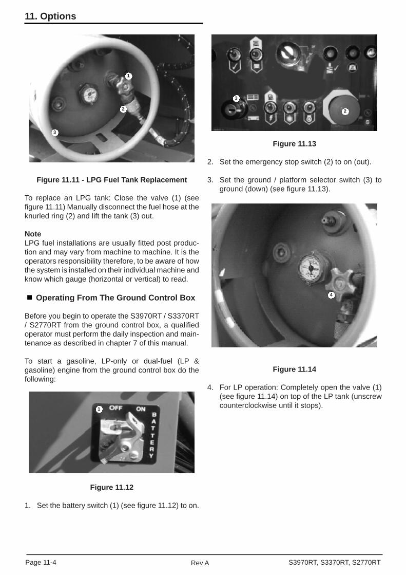
Figure 11.11 - LPG Fuel Tank Replacement
To replace an LPG tank: Close the valve (1) (see fi gure 11.11) Manually disconnect the fuel hose at the knurled ring (2) and lift the tank (3) out.
NoteLPG fuel installations are usually fi tted post produc-tion and may vary from machine to machine. It is the operators responsibility therefore, to be aware of how the system is installed on their individual machine and know which gauge (horizontal or vertical) to read.
Operating From The Ground Control Box
Before you begin to operate the S3970RT / S3370RT / S2770RT from the ground control box, a qualifi ed operator must perform the daily inspection and main-tenance as described in chapter 7 of this manual.
To start a gasoline, LP-only or dual-fuel (LP & gasoline) engine from the ground control box do the following:
Figure 11.12
1. Set the battery switch (1) (see fi gure 11.12) to on.
Figure 11.13
2. Set the emergency stop switch (2) to on (out).
3. Set the ground / platform selector switch (3) to ground (down) (see fi gure 11.13).
Figure 11.14
4. For LP operation: Completely open the valve (1) (see fi gure 11.14) on top of the LP tank (unscrew counterclockwise until it stops).
3
1
2
4
3
2
1
Page 11-4 Rev A S3970RT, S3370RT, S2770RT
11. Options
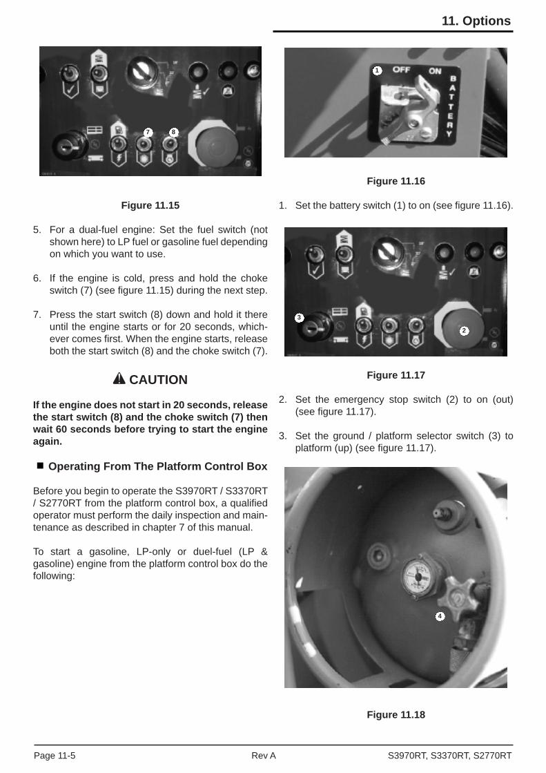
Figure 11.15
5. For a dual-fuel engine: Set the fuel switch (not shown here) to LP fuel or gasoline fuel depending on which you want to use.
6. If the engine is cold, press and hold the choke switch (7) (see fi gure 11.15) during the next step.
7. Press the start switch (8) down and hold it there until the engine starts or for 20 seconds, which-ever comes fi rst. When the engine starts, release both the start switch (8) and the choke switch (7).
CAUTION
If the engine does not start in 20 seconds, release the start switch (8) and the choke switch (7) then wait 60 seconds before trying to start the engine again.
Operating From The Platform Control Box
Before you begin to operate the S3970RT / S3370RT / S2770RT from the platform control box, a qualifi ed operator must perform the daily inspection and main-tenance as described in chapter 7 of this manual.
To start a gasoline, LP-only or duel-fuel (LP & gasoline) engine from the platform control box do the following:
Figure 11.16
1. Set the battery switch (1) to on (see fi gure 11.16).
Figure 11.17
2. Set the emergency stop switch (2) to on (out) (see fi gure 11.17).
3. Set the ground / platform selector switch (3) to platform (up) (see fi gure 11.17).
Figure 11.18
7 8
1
3
2
4
S3970RT, S3370RT, S2770RTRev APage 11-5
11. Options
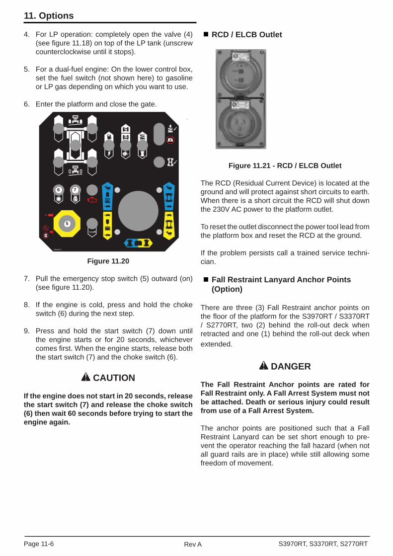
4. For LP operation: completely open the valve (4) (see fi gure 11.18) on top of the LP tank (unscrew counterclockwise until it stops).
5. For a dual-fuel engine: On the lower control box, set the fuel switch (not shown here) to gasoline or LP gas depending on which you want to use.
6. Enter the platform and close the gate.
Figure 11.20
7. Pull the emergency stop switch (5) outward (on) (see fi gure 11.20).
8. If the engine is cold, press and hold the choke switch (6) during the next step.
9. Press and hold the start switch (7) down until the engine starts or for 20 seconds, whichever comes fi rst. When the engine starts, release both the start switch (7) and the choke switch (6).
CAUTION
If the engine does not start in 20 seconds, release the start switch (7) and release the choke switch (6) then wait 60 seconds before trying to start the engine again.
RCD / ELCB Outlet
Figure 11.21 - RCD / ELCB Outlet
The RCD (Residual Current Device) is located at the ground and will protect against short circuits to earth. When there is a short circuit the RCD will shut down the 230V AC power to the platform outlet.
To reset the outlet disconnect the power tool lead from the platform box and reset the RCD at the ground.
If the problem persists call a trained service techni-cian.
Fall Restraint Lanyard Anchor Points (Option)
There are three (3) Fall Restraint anchor points on the fl oor of the platform for the S3970RT / S3370RT / S2770RT, two (2) behind the roll-out deck when retracted and one (1) behind the roll-out deck when extended.
DANGER
The Fall Restraint Anchor points are rated for Fall Restraint only. A Fall Arrest System must not be attached. Death or serious injury could result from use of a Fall Arrest System.
The anchor points are positioned such that a Fall Restraint Lanyard can be set short enough to pre-vent the operator reaching the fall hazard (when not all guard rails are in place) while still allowing some freedom of movement.
5
6 7
Page 11-6 Rev A S3970RT, S3370RT, S2770RT
11. Options
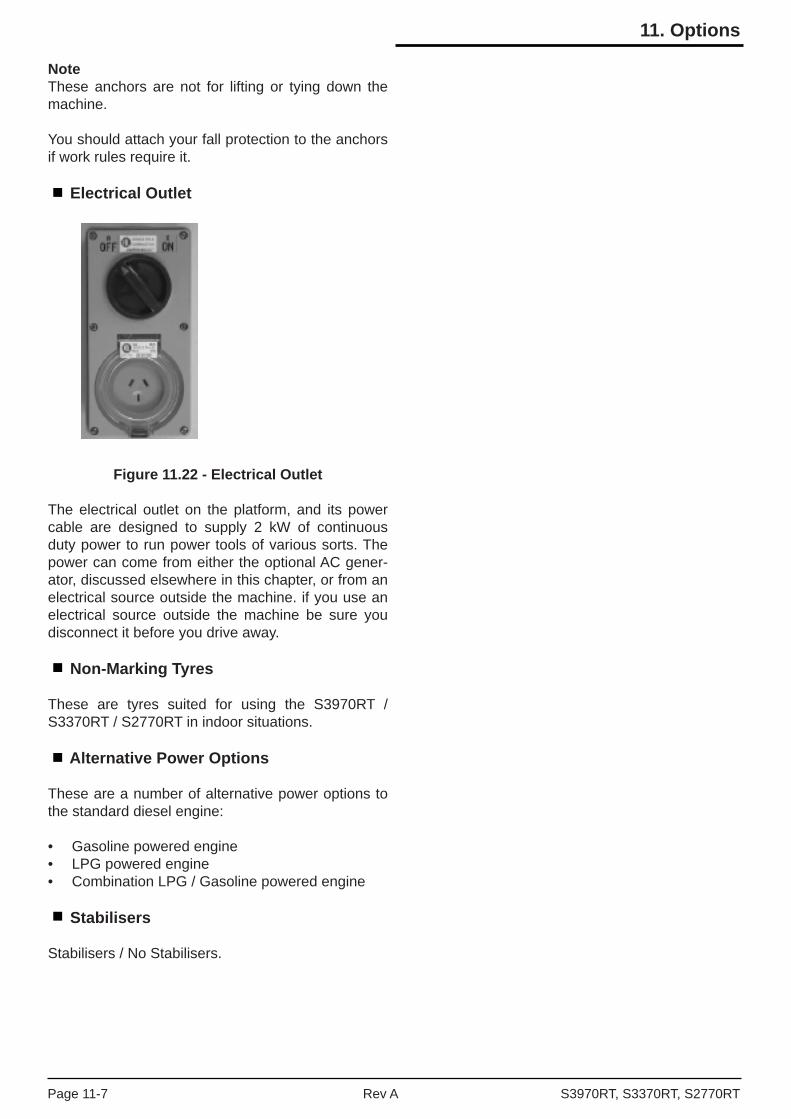
NoteThese anchors are not for lifting or tying down the machine.
You should attach your fall protection to the anchors if work rules require it.
Electrical Outlet
Figure 11.22 - Electrical Outlet
The electrical outlet on the platform, and its power cable are designed to supply 2 kW of continuous duty power to run power tools of various sorts. The power can come from either the optional AC gener-ator, discussed elsewhere in this chapter, or from an electrical source outside the machine. if you use an electrical source outside the machine be sure you disconnect it before you drive away.
Non-Marking Tyres
These are tyres suited for using the S3970RT / S3370RT / S2770RT in indoor situations.
Alternative Power Options
These are a number of alternative power options to the standard diesel engine:
• Gasoline powered engine• LPG powered engine• Combination LPG / Gasoline powered engine
Stabilisers
Stabilisers / No Stabilisers.
S3970RT, S3370RT, S2770RTRev APage 11-7
11. Options

Page 11-8 Rev A S3970RT, S3370RT, S2770RT
11. Options
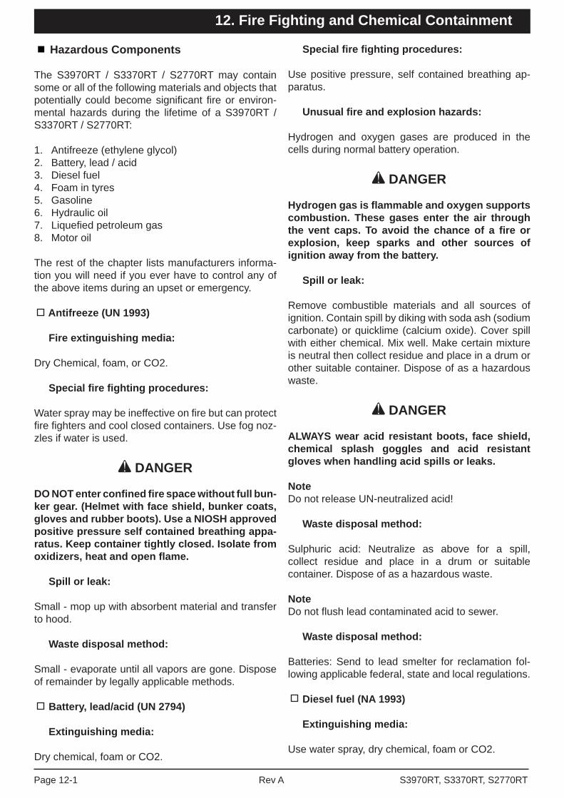
Hazardous Components
The S3970RT / S3370RT / S2770RT may contain some or all of the following materials and objects that potentially could become signifi cant fi re or environ-mental hazards during the lifetime of a S3970RT / S3370RT / S2770RT:
1. Antifreeze (ethylene glycol)2. Battery, lead / acid3. Diesel fuel4. Foam in tyres5. Gasoline6. Hydraulic oil7. Liquefi ed petroleum gas8. Motor oil
The rest of the chapter lists manufacturers informa-tion you will need if you ever have to control any of the above items during an upset or emergency.
Antifreeze (UN 1993)
Fire extinguishing media:
Dry Chemical, foam, or CO2.
Special fi re fi ghting procedures:
Water spray may be ineffective on fi re but can protect fi re fi ghters and cool closed containers. Use fog noz-zles if water is used.
DANGER
DO NOT enter confi ned fi re space without full bun-ker gear. (Helmet with face shield, bunker coats, gloves and rubber boots). Use a NIOSH approved positive pressure self contained breathing appa-ratus. Keep container tightly closed. Isolate from oxidizers, heat and open fl ame.
Spill or leak:
Small - mop up with absorbent material and transfer to hood.
Waste disposal method:
Small - evaporate until all vapors are gone. Dispose of remainder by legally applicable methods.
Battery, lead/acid (UN 2794)
Extinguishing media:
Dry chemical, foam or CO2.
Special fi re fi ghting procedures:
Use positive pressure, self contained breathing ap-paratus.
Unusual fi re and explosion hazards:
Hydrogen and oxygen gases are produced in the cells during normal battery operation.
DANGER
Hydrogen gas is fl ammable and oxygen supports combustion. These gases enter the air through the vent caps. To avoid the chance of a fi re or explosion, keep sparks and other sources of ignition away from the battery.
Spill or leak:
Remove combustible materials and all sources of ignition. Contain spill by diking with soda ash (sodium carbonate) or quicklime (calcium oxide). Cover spill with either chemical. Mix well. Make certain mixture is neutral then collect residue and place in a drum or other suitable container. Dispose of as a hazardous waste.
DANGER
ALWAYS wear acid resistant boots, face shield, chemical splash goggles and acid resistant gloves when handling acid spills or leaks.
NoteDo not release UN-neutralized acid!
Waste disposal method:
Sulphuric acid: Neutralize as above for a spill, collect residue and place in a drum or suitable container. Dispose of as a hazardous waste.
NoteDo not fl ush lead contaminated acid to sewer.
Waste disposal method:
Batteries: Send to lead smelter for reclamation fol-lowing applicable federal, state and local regulations.
Diesel fuel (NA 1993)
Extinguishing media:
Use water spray, dry chemical, foam or CO2.
S3970RT, S3370RT, S2770RTRev APage 12-1
12. Fire Fighting and Chemical Containment

12. Fire Fighting and Chemical Containment
Special fi re fi ghting procedures:
Use water to keep fi re exposed containers cool. If leak or spill has not ignited, use water spray to disperse the vapors and to provide protection for personnel attempting to stop a leak. Water spray may be used to fl ush spills away from exposures.
Unusual fi re and explosion hazards:
Products of combustion may contain carbon monox-ide, carbon dioxide and other toxic materials.
DANGER
DO NOT enter enclosed or confi ned space without proper protective equipment including respiratory protection.
Spill or leak:
Contain spill immediately in smallest area possible. Recover as much of the product itself as possible by such methods as vacuuming, followed by soaking up of residual fl uids by use of absorbent materials.
Remove contaminated items including contaminated soil and place in proper containers for disposal. Avoidwashing, draining or directing material to storm or sanitary sewers.
Waste disposal method:
Recycle as much of the recoverable product as possible.
Dispose of non-recyclable material as a RCRA haz-ardous waste by such methods as incineration, complying with federal, state and local regulations.
Foam in tyres
Extinguishing media:
Water, dry chemical, foam or CO2.
Special fi re fi ghting procedures:
Evacuate non emergency personnel to a safe area.
Unusual fi re and explosion hazards:
Fire fi ghters should use self contained breathing apparatus. Avoid breathing smoke, fumes and de-composition products. Use water spray to drench smoldering elastomer. Product may melt after ignitionto form fl ammable liquid.
DANGER
Burning procedures intense heat, dense smoke and toxic gases such as carbon monoxide, ox-ides of nitrogen and traces of hydrogen cyanide.
Spill or leak:
Pick up and handle as any other inert solid material.
Waste disposal method:
Not considered a hazardous material. Dispose of material according to any local, state and federal reg-ulations.
Gasoline (UN 1203)
Extinguishing media:
Dry chemical, foam or CO2.
Special fi re fi ghting procedures:
Water may be ineffective to extinguish, but water should be used to keep fi re exposed containers cool. If a leak or spill has not ignited, use water spray to disperse the vapors and to protect personnel at-tempting to stop a leak. Water spray may be used to fl ush spills away from areas of potential ignition.
Unusual fi re and explosion hazards:
Highly fl ammable. Products of combustion may con-tain carbon monoxide, carbon dioxide and other toxic materials.
DANGER
DO NOT enter enclosed or confi ned space without proper protective equipment including respiratory protection.
Spill or leak:
Review fi re and explosion hazards before proceeding with clean up. Use appropriate personal protective equipment during clean up. Dike spill. Prevent liq-uid from entering sewers, water ways, or low areas. Soak up with sawdust, sand, oil dry or other absor-bent material. Shovel or sweep up.
Remove source of heat, sparks, fl ame, impact, friction or electricity including internal combustion engines and power tools. If equipment is used for spill cleanup, it must be explosion proof and suitable for fl ammable liquid and vapor.
Page 12-2 Rev A S3970RT, S3370RT, S2770RT
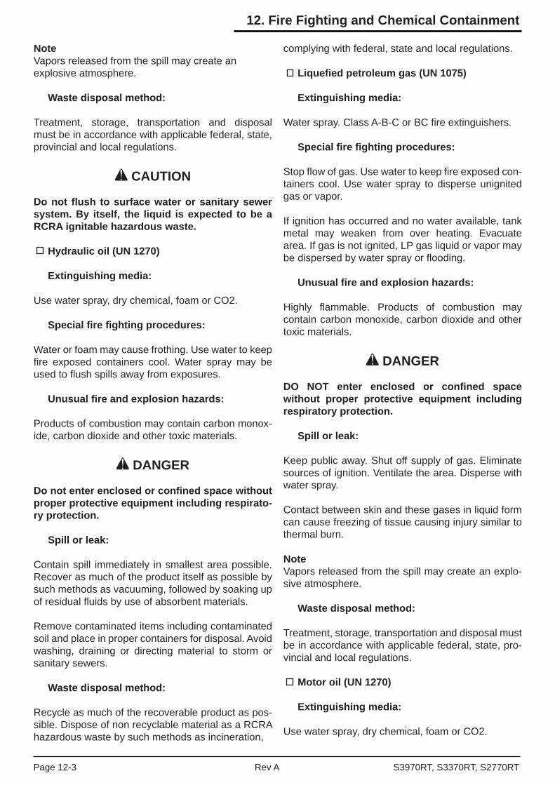
12. Fire Fighting and Chemical Containment
NoteVapors released from the spill may create anexplosive atmosphere.
Waste disposal method:
Treatment, storage, transportation and disposal must be in accordance with applicable federal, state, provincial and local regulations.
CAUTION
Do not fl ush to surface water or sanitary sewer system. By itself, the liquid is expected to be a RCRA ignitable hazardous waste.
Hydraulic oil (UN 1270)
Extinguishing media:
Use water spray, dry chemical, foam or CO2.
Special fi re fi ghting procedures:
Water or foam may cause frothing. Use water to keep fi re exposed containers cool. Water spray may be used to fl ush spills away from exposures.
Unusual fi re and explosion hazards:
Products of combustion may contain carbon monox-ide, carbon dioxide and other toxic materials.
DANGER
Do not enter enclosed or confi ned space without proper protective equipment including respirato-ry protection.
Spill or leak:
Contain spill immediately in smallest area possible. Recover as much of the product itself as possible by such methods as vacuuming, followed by soaking up of residual fl uids by use of absorbent materials.
Remove contaminated items including contaminated soil and place in proper containers for disposal. Avoidwashing, draining or directing material to storm or sanitary sewers.
Waste disposal method:
Recycle as much of the recoverable product as pos-sible. Dispose of non recyclable material as a RCRA hazardous waste by such methods as incineration,
complying with federal, state and local regulations.
Liquefi ed petroleum gas (UN 1075)
Extinguishing media:
Water spray. Class A-B-C or BC fi re extinguishers.
Special fi re fi ghting procedures:
Stop fl ow of gas. Use water to keep fi re exposed con-tainers cool. Use water spray to disperse unignited gas or vapor.
If ignition has occurred and no water available, tank metal may weaken from over heating. Evacuate area. If gas is not ignited, LP gas liquid or vapor may be dispersed by water spray or fl ooding.
Unusual fi re and explosion hazards:
Highly fl ammable. Products of combustion may contain carbon monoxide, carbon dioxide and other toxic materials.
DANGER
DO NOT enter enclosed or confi ned space without proper protective equipment including respiratory protection.
Spill or leak:
Keep public away. Shut off supply of gas. Eliminate sources of ignition. Ventilate the area. Disperse with water spray.
Contact between skin and these gases in liquid form can cause freezing of tissue causing injury similar to thermal burn.
NoteVapors released from the spill may create an explo-sive atmosphere.
Waste disposal method:
Treatment, storage, transportation and disposal must be in accordance with applicable federal, state, pro-vincial and local regulations.
Motor oil (UN 1270)
Extinguishing media:
Use water spray, dry chemical, foam or CO2.
S3970RT, S3370RT, S2770RTRev APage 12-3

Special fi re fi ghting procedures:
Water or foam may cause frothing. Use water to keep fi re exposed containers cool. Water spray may be used to fl ush spills away from exposures.
Unusual fi re and explosion hazards:
Products of combustion may contain carbon monoxide, carbon dioxide and other toxic materials.
DANGER
DO NOT enter enclosed or confi ned space without proper protective equipment including respiratory protection.
Spill or leak:
Contain spill immediately in smallest area possible. Recover as much of the product itself as possible by such methods as vacuuming, followed by soaking up of residual fl uids by use of absorbent materials.
Remove contaminated items including contaminated soil and place in proper containers for disposal. Avoidwashing, draining or directing material to storm or sanitary sewers.
Waste disposal method:
Recycle as much of the recoverable product as possible.
Dispose of non-recyclable material as a RCRA haz-ardous waste by such methods as incineration, complying with federal, state and local regulations.
Page 12-4 Rev A S3970RT, S3370RT, S2770RT
12. Fire Fighting and Chemical Containment

Problem Cause Remedy
Engine will not start. Battery switch set to off. Turn battery switch to on.
Emergency Stopswitch(es) not on.
Set the ground control Emergency Stopswitch to on (up). Also, if you are trying tostart at the platform control box youshould pull the Emergency Stop switch, atthe platform control box, until it pops out(on).
Key switch set to off. Set the Key switch to on (the bar symbol).
Ground/Platform Selectorswitch set to wronglocation.
If you are trying to start from the groundcontrol box, set the Ground/Platformselector to ground (down). If you are trying to start from the platform, set the selectorto platform (up).
Fuse blown. Replace fuse.
Fuel switch not setcorrectly.
If you are trying to start a dual-fuel enginebe sure the fuel switch is set to the correct fuel.
Out of fuel. DANGER: Keep flames and lit tobacco away fromopen fuel tanks.
Remove the cap from the gasoline ordiesel tank to see if there is fuel.
Check the gauge(s) on top of the LPtank(s). If you are using LP gas, be surethe valve on top of the tank is open.
Clogged air filter. Visually check the air filter gauge.
Engine oil too thick forambient temperature.
Check engine oil chart in “Specifications”chapter 3 for correct oil weight.
Stabilisers inoperative Platform not completelydown.
Completely lower the platform.
All systems sluggish. Hydraulic oil is too thick. Check for correct grade of Hydraulic Oil.
Allow time for machine to warm up.
S3970RT / S3370RT /S2770RT will not driveforward or reverse.
Free-wheeling valve isopen.
Close the free-wheeling valve.
Troubleshooting
All of the actions described in this chapter may be performed by the machine operator, a trained and qualifi ed service technician is not required.
The fi rst column of the following charts lists some common problems encountered by the S3970RT / S3370RT / S2770RT operators.
Operator troubleshooting chart
The second column lists some of the causes for each problem. The third column lists remedies.
CAUTION
Any problem that cannot be fi xed by actions listed below should be referred to a trained and qualifi ed S3970RT / S3370RT / S3370RT service technician.
S3970RT, S3370RT, S2770RTRev APage 13-1
13. Operators Troubleshooting

Problem Cause Remedy
Platform will not go upor down.
Engine is not running. Start the engine from the control stationwhere you will operate the S3970RT /S3370RT / S2770RT.
Switches set wrong(Lift Indicator light is lit).
For ground control operation:
Ground/Platform Selector = Ground
For platform control box operation:
Ground/Platform Selector = PlatformLift/Drive Selector = Lift
Squeeze and hold the Safety Control thenpush Joystick Controller forward to go upor pull it backward to go down.
S3970RT / S3370RT /S2770RT is not level.(Lift Indicator light is not lit and the Level SensorAlarm is sounding).
Use the stabilisers to level the S3970RT /S3370RT / S2770RT.
The Stabilisers are notproperly set.(Lift Indicator light is notlit).
If you are using the stabilisers, one (1) ormore of them is not down quite farenough. Lower each stabiliser a fewinches more to be sure each is firmly incontact with the ground.
If you are not using the stabilisers, one (1) or more of them is not fully up. Raise each stabiliser completely up.
Platform will not driveforward or reversewhen raised.
Unit not level.Articulating axle operated.
Situation normal, lower platform to drive.
Page 13-2 Rev A S3970RT, S3370RT, S2770RT
13. Operators Troubleshooting

S3970RT, S3370RT, S2770RTRev A
Appendix A. Glossary
• Aerial platformA mobile device that has an adjustable position platform, supported from ground level by a structure.
• Ambient temperatureThe air temperature of the immediate environment.
• AmmeterAn instrument for measuring the strength of an electric current in amperes.
• Authorised personnelPersonnel approved as assigned to perform specifi c duties at a specifi c location.
• BaseThe relevant contact points of the aerial platform that form the stability support (e.g. wheels, casters, outriggers, stabilisers).
• BoomA movable cantilever beam which supports the platform.
• Center of gravityThe point in the aerial platform around which its weight is evenly balanced.
• ChassisThe integral part of the aerial platform that provides mobility and support for the booms.
• Fall arrest systemIs the form of fall protection which involves the safe stopping of a person already falling. The system includes:
A: Anchorage - a fi xed structure to which the components of the system are rigged.
B: Body Wear - a full body harness worn by the person (referred to as a “safety harness” in this manual).
C: Connector - a subsystem component connecting the harness to the anchorage, such as a lanyard.
D: Deceleration Device - a subsystem component designed to dissipate the forces associated with a fall arrest event.
• Fall arrestIs the form of personal fall protection which prevents persons who are in a fall hazard area from falling. The system includes:
A: Anchorage - a fi xed structure to which the components of the system are rigged.
B: Body Wear - a full body harness worn by the person (referred to as a “safety harness” in this manual).
C: Connector - a subsystem component connecting the harness to the anchorage, such as a lanyard. The lanyard is short enough that the person can not reach the fall hazard.
• Ground pressureThe maximum pressure, expressed in pounds per square inch, a single wheel concentrates on the fl oor or ground.
• GradeabilityThe maximum slope that the aerial platform is capable of travel.
• Ground fault circuit interrupter or residual current detector
A fast acting circuit breaker that opens to stop electrical circuit fl ow if it senses a very small current leakage to ground. The GFCI/RCD is used to protect personnel against a potential shock hazard from defective electrical tools or wiring.
• Guardrail systemThe primary fall protection system to eliminate the fall hazard. The system includes toe boards, midrail, toprail and uprights.
• Hazardous locationAny location that contains, or has the potential to contain, an explosive or fl ammable atmosphere as defi ned by ANSI/NFPA 505.
• Jib boomA boom assembly located between the main boom and the platform.
• Level SensorA device that detects a present degree of varia-tion from perfect level. The level sensor is used to sound an alarm if operating on a slope greater than the present value. it may also (depending on the machine) prevent it from operating further until it is bought back within the present parameters.
• Lower controlsThe controls located at ground level for operating some or all of the functions of the aerial platform.
Rev A S3970RT, S3370RT, S2770RT
• Main boomA boom assembly located between the turntable and the platform or jib boom. The main boom includes the base, intermediate and tip boom.
• Maximum travel heightThe maximum platform height or the most adverse confi guration(s) with respect to stability in which travel is permitted by the manufacturer.
• Minimum safe approach distanceThe minimum safe distance that electrical con-ductors may be approached when using the aerial platform. Also called MST.
• OperationThe performance of an aerial platform functions within the scope of its specifi cations and in accor-dance with the manufacturers instructions, the users work rules and all applicable governmental regula-tions.
• OperatorA qualifi ed person who controls the movement of an aerial platform.
• PlatformThe portion of an aerial platform intended to be occupied by personnel with their tools and materials.
• Platform heightThe vertical distance measured from the fl oor of the platform to the surface upon which the chassis is being supported.
• Prestart inspectionA required safety inspection routine that is per-formed daily before operating the aerial platform.
• Qualifi ed personA person, who by reason of knowledge, experience or training is familiar with the operation to be per-formed and the hazards involved.
• Rated work loadThe designed carrying capacity of the aerial platform in its rest position.
• StowTo place a component, such as the platform, in its rest position.
• Turning radiusThe radius of the circle created by the wheel during a 360 degree turn with the steering wheels turned to maximum. Inside turning radius is the wheel closest
to the center and outside turning radius is the wheel farthest from the center.
• TurntableThe structure above the rotation bearing which supports the main boom. The turntable rotates about the centerline of the rotation.
• Unrestricted rated work loadThe maximum designed carrying capacity of the aerial platform allowed by the manufacturer in all operating confi gurations.
• Upper controlsThe controls located on or beside the platform used for operating some or all of the functions of the aeri-al platform.
• WheelbaseThe distance from the center of the rear wheel to the center of the front wheel.
• Working envelopeThe area defi ned by the horizontal and vertical limits of boom travel that the platform may be positioned in.
Appendix A. Glossary

Local Distributor / Lokaler Vertiebshandler / Distributeur localEl Distribuidor local / Il Distributore locale
EUROPE, MIDDLE EASTAFRICA & ASIA
PHONE: +44 (0) 845 1550 O57
FAX: +44 (0) 845 1557 756
NORTH & SOUTH AMERICA
PHONE: +1 785 989 3000
TOLL FREE: +1 800 255 0317
FAX: +1 785 989 3070
AUSTRALIA
PHONE: +64 2 9725 4000FAX: +64 2 9609 3057
NEW ZEALAND
PHONE: +64 6 3689 168FAX: +64 6 3689 164