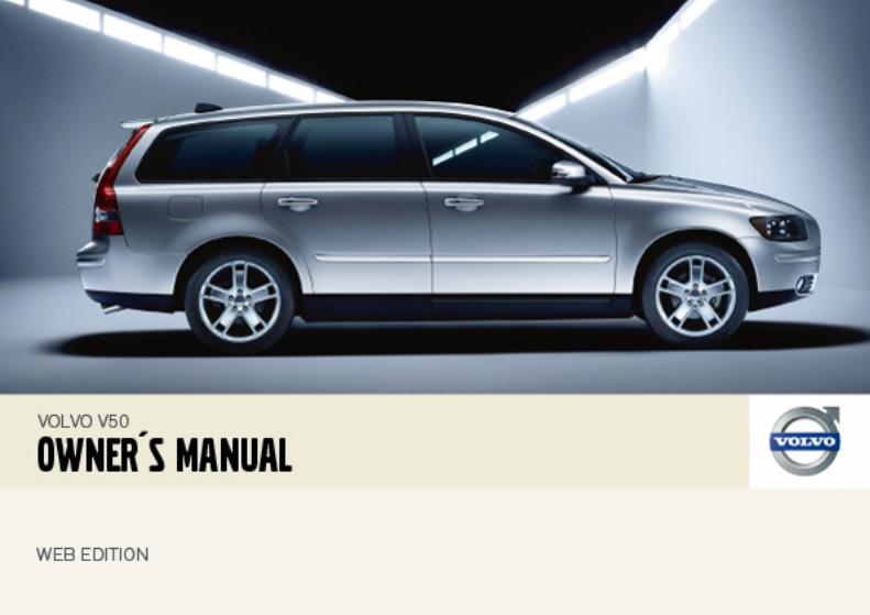
v50 ownersmanual my07 en tp8970-web
DESCRIPTION
V50 OwnersManual MY07 en TP8970-WebTRANSCRIPT

DEAR VOLVO OWNERTHANK YOU FOR CHOOSING VOLVO
We hope that you will enjoy many years of driving pleasure in your Volvo. The car has been designed for the safety and com-fort of you and your passengers. Volvo is one of the safest cars in the world. Your Volvo has also been designed to satisfy all current safety and environmental requirements.
In order to increase your enjoyment of the car, we recommend that you familiarise yourself with the equipment, instructions and maintenance information contained in this Owner’s Manual.
Contents
2
00 IntrodIntroductioVolvo Cars
02 Instruments and controlsOverview, left-hand drive cars .......... 36Overview, right-hand drive cars ........ 38Driver’s door control panel ............... 40Combined instrument panel .............41Indicator and warning symbols......... 42Information display ........................... 47Electrical socket and switches on centre console .................................. 48Lighting panel ................................... 49Left-hand stalk switch ...................... 51Right-hand stalk switch .................... 53Cruise control (option) ...................... 55Steering wheel keypad (option) ........ 57Steering wheel adjustment, hazard warning flashers................................ 58Parking brake, electrical socket ........ 59Power windows................................. 60Rearview and door mirrors ............... 62Power sunroof (option)...................... 66Personal preferences ........................ 68
uctionn ........................................6 and the environment .........7
01 SafetySeatbelts .......................................... 12Airbag system .................................. 15Airbags (SRS) ................................... 16Activating/deactivating the airbag (SRS) ................................................ 19Side airbags (SIPS bags).................. 21Inflatable Curtain (IC) ....................... 23WHIPS.............................................. 24When the systems deploy................ 26Crash mode...................................... 27Child safety ...................................... 28
Contents
3
03 ClimGeneral incontrol ...Manual cElectronic(option) ..Air distribFuel-drive
05 Locks and alarmRemote control with key blade....... 100Keyless drive (option) ..................... 104Locking and unlocking ................... 107Child safety locks ........................... 110Alarm (option) .................................. 111
ate controlformation on climate
........................................... 72limate control, A/C.............. 74 climate control, ECC
........................................... 76ution .................................. 79n heater (option ................ 80
04 InteriorFront seats ........................................84Interior lighting .................................. 86Storage spaces in the passenger compartment .................................... 88Rear seat........................................... 90Cargo area ........................................ 92
Contents
4
06 StartinGeneral ....Refuelling.Starting thKeyless drManual geaAutomatic All-wheel dBrake systStability ancontrol sysParking assBlind Spotoption) .....Towing andStart assisDriving witTowing equDetachableLoading....Adjusting h
08 Car careCleaning.......................................... 172Touching up paintwork.................... 175Rustproofing ................................... 176
g and driving........................................ 116....................................... 118e engine ......................... 119ive (option) ..................... 121rbox.............................. 122
gearbox ......................... 124rive ................................ 127
em................................... 128d traction tem................................ 130istance (option)............. 132
Information System (BLIS, ....................................... 134 recovery....................... 137
tance.............................. 139h a trailer........................ 140ipment .......................... 142 towbar ......................... 144
....................................... 149eadlamp pattern ........... 150
07 Wheels and tyresGeneral........................................... 154Tyre pressure .................................. 158Warning triangle and spare wheel.. 160Changing wheels............................ 161Emergency puncture repair ............ 163

Contents
5
09 MainVolvo serSelf-mainBonnet aDiesel.....Oils and fWiper blaBattery...ReplacingFuses.....
11 SpecificationsType designation............................. 232Dimensions and weights ................ 233Engine specifications ..................... 234Engine oil ........................................ 236Fluids and lubricants ...................... 240Fuel ................................................. 242Catalytic converter ......................... 245Electrical system ............................ 246
tenance and servicevice .................................. 180tenance ........................... 181nd engine compartment .. 182......................................... 183luids ................................ 184des .................................. 189........................................ 190 bulbs ............................. 192
......................................... 198
10 Infotainment systemGeneral ...........................................208Audio functions ...............................209Radio functions ...............................211CD functions ...................................215Menu structure – audio system ......217Phone functions (option) .................218Menu structure – phone ..................225
Introduction
6
Intro
Owner
A good is to reayour firsportunitfunctionin differeuse of atention tthe man
The equManual tion to sdescribeand cert
W
"Warnirisk of structio
IM
"Importo the cbeing f
duction
’s Manual
way of getting to know your new car d the Owner’s Manual, ideally before t journey. This will give you the op-y to familiarise yourself with new s, to see how best to handle the car nt situations, and to make the best
ll the car’s features. Please pay at-o the safety instructions contained in ual:
ipment described in the Owner’s is not available in all models. In addi-tandard equipment, this manual also s options (factory fitted equipment) ain accessories (extra equipment).
The specifications, design features and illus-trations in this Owner’s Manual are not bind-ing. We reserve the right to make modifica-tions without prior notice.
© Volvo Car CorporationARNING
ng!" texts indicate where there is a personal injury in the event of the in-ns not being followed.
PORTANT
tant!" texts indicate a risk of damage ar in the event of the instructions not ollowed.
NOTE
Volvo cars are adapted for the varying re-quirements of different markets, as well as for national or local legal requirements and regulations.
Introduction
7
Volvo Cars and the environment
Volvo C
Environmthe threerationsalso belconside
Your Voenvironmfacturedsource-Car Corthe ISO which sthe envi
It is possible for the driver to influence fuel consumption. For more information read un-der the heading Reducing environmental im-pact on page 9.
ars’ environmental philosophy
ental care, safety and quality are e core values which influence all op- of the Volvo Car Corporation. We ieve that our customers share our ration for the environment.
lvo complies with strict international ental standards and is also manu-
in one of the cleanest and most re-efficient plants in the world. Volvo poration has global certification to 14001 environmental standard, upports the work within the area of ronment.
EPI (Environmental Product Information) is supplied for all Volvo models. You can now compare the environmental impact of differ-ent models and engines during the entire life-cycle.
Read more at www.volvocars.com/EPI
Fuel consumptionVolvo cars have competitive fuel consump-tion in each of their respective classes. Low-er fuel consumption generally results in lower emission of the greenhouse gas, carbon di-oxide.
Introduction
8
Volvo
EfficienYour Voconceptthat encment astrol. In mwell belo
In additiPremAirground-the ozonozone cconverte
Clean acompaA passedust andcompar
A sophisterior Aicoming outside.
The sysand a ca
consumption, and this way you contribute to a cleaner environment. When Volvo’s work-shops are entrusted with the repair and maintenance of the car, it becomes part of our system. We make clear demands regard-ing the way in which our workshops are de-signed in order to prevent spills and dis-charges into the environment. Our workshop staff have the knowledge and the tools re-quired to guarantee good environmental care.
1 Option PremAirhard Co
2 Option
Cars and the environment
t emission control lvo is manufactured following the Clean inside and out – a concept ompasses a clean interior environ- well as highly efficient emission con-any cases the exhaust emissions are w the applicable standards.
on there is a special radiator coating, ®1, which can convert hazardous level ozone into pure oxygen when e passes the radiator. The higher the
ontent in the air the more ozone is d.
ir in the passenger rtmentnger compartment filter prevents pollen from entering the passenger
tment via the air intake.
ticated air quality system, IAQS2 (In-r Quality System) ensures that the in-air is cleaner than the air in the traffic
tem consists of an electronic sensor rbon filter. The incoming air is moni-
tored continuously and if there is an increase in the level of certain unhealthy gases such as carbon monoxide then the air intake is closed. Such a situation may arise in heavy traffic, queues and tunnels for example.
The entry of nitrous oxides, ground-level ozone and hydrocarbons is prevented by the carbon filter.
Textile standardThe interior of a Volvo is designed to be pleasant and comfortable, even for people with contact allergies and for asthma suffer-ers. All of our upholstery and interior textiles are tested with respect to certain unhealthy substances and allergens as well as emis-sions. This means that all textiles fulfil the re-quirements in the Öko-Tex 1003 standard, a major advance towards a healthier passen-ger compartment environment.
Öko-Tex certification covers seatbelts, car-pets, thread and fabrics for example. The leather in the upholstery undergoes chromi-um-free tanning with natural plant substanc-es and fulfils the certification requirements.
Volvo workshops and the environmentRegular maintenance creates the conditions for long service life for the car and low fuel
for 5-cylinder engines. ® is a registered trademark of Engel-rporation.
3 More information on www.oekotex.com
Introduction
9
ReducYou canfor examchasingby serviing to th
The follofor the e
• DecreECO
• A rooincreancecantlconsthemuse.
• Remothe gcons
• Is youheatestartisump
• Drive
ing environmental impact help reduce environmental impact, ple, by driving economically, by pur-
eco-labelled car care products and cing and maintaining the car accord-e instructions in the Owner’s Manual.
wing hints will help you to do your bit nvironment:
ase fuel consumption by choosing tyre pressure, see page 158.f load and ski box ase wind resist-, leading to signifi-y higher fuel umption. Remove immediately after
ve unnecessary items from the car - reater the load the higher the fuel umption.r car equipped with an engine block r? If so, use it for a few hours before ng from cold to reduce fuel con-tion and exhaust emissions. gently and avoid braking too hard.
• Drive in the highest gear possible. Low engine speeds result in lower fuel consumption.
• Use engine braking to slow down.
• Avoid idling. Take consideration of local regulations. Switch off the engine in longer stationary traffic.
• Always dispose of envi-ronmentally hazardous waste, such as batteries and oils, in an environ-mentally safe manner. If uncertain about disposal, consult an authorised Volvo workshop for advice.
• Service your car regularly.• High speed increases consumption con-
siderably due to increased wind resist-ance. A doubling of speed increases wind resistance four times.
These hints will help you to reduce your fuel consumption without increasing your travel time or lessening the enjoyment of driving. Apart from being kind to your car, you’ll be saving money - and the Earth’s resources.
10
Seatbelts .................................................................................................. 12Airbag system .......................................................................................... 15Airbags (SRS) ........................................................................................... 16Activating/deactivating the airbag (SRS) ........................................................................................................ 19Side airbags (SIPS bags) ......................................................................... 21Inflatable Curtain (IC) ............................................................................... 23WHIPS...................................................................................................... 24When the systems deploy........................................................................ 26Crash mode.............................................................................................. 27Child safety .............................................................................................. 28
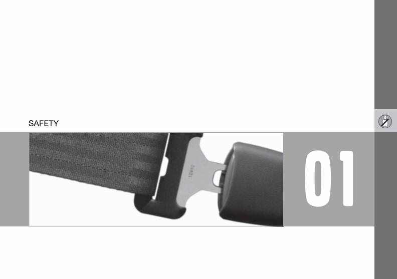
01SAFETY
01 Safety
12
Seat01
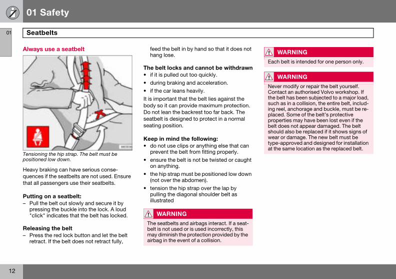
Always
Tensionipositione
Heavy bquencesthat all p
Putting– Pull t
press"click
Releas– Press
retrac
WARNING
Each belt is intended for one person only.
WARNING
Never modify or repair the belt yourself. Contact an authorised Volvo workshop. If the belt has been subjected to a major load, such as in a collision, the entire belt, includ-ing reel, anchorage and buckle, must be re-placed. Some of the belt’s protective properties may have been lost even if the belt does not appear damaged. The belt should also be replaced if it shows signs of wear or damage. The new belt must be type-approved and designed for installation at the same location as the replaced belt.
belts
use a seatbelt
ng the hip strap. The belt must be d low down.
raking can have serious conse- if the seatbelts are not used. Ensure assengers use their seatbelts.
on a seatbelt:he belt out slowly and secure it by ing the buckle into the lock. A loud " indicates that the belt has locked.
ing the belt the red lock button and let the belt t. If the belt does not retract fully,
feed the belt in by hand so that it does not hang lose.
The belt locks and cannot be withdrawn• if it is pulled out too quickly.• during braking and acceleration.• if the car leans heavily.It is important that the belt lies against the body so it can provide maximum protection. Do not lean the backrest too far back. The seatbelt is designed to protect in a normal seating position.
Keep in mind the following:• do not use clips or anything else that can
prevent the belt from fitting properly.• ensure the belt is not be twisted or caught
on anything.• the hip strap must be positioned low down
(not over the abdomen).• tension the hip strap over the lap by
pulling the diagonal shoulder belt as illustrated
WARNING
The seatbelts and airbags interact. If a seat-belt is not used or is used incorrectly, this may diminish the protection provided by the airbag in the event of a collision.
01 Safety
13
Seatbelts 01
Seatbe
Unbelteten theiral reminpendentroof conpanel. Asound fo
Child sereminde
Rear seThe seatwo sub
• Proviare b
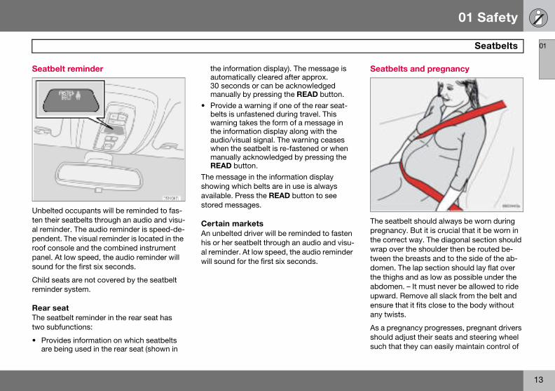
Seatbelts and pregnancy
The seatbelt should always be worn during pregnancy. But it is crucial that it be worn in the correct way. The diagonal section should wrap over the shoulder then be routed be-tween the breasts and to the side of the ab-domen. The lap section should lay flat over the thighs and as low as possible under the abdomen. – It must never be allowed to ride upward. Remove all slack from the belt and ensure that it fits close to the body without any twists.
As a pregnancy progresses, pregnant drivers should adjust their seats and steering wheel such that they can easily maintain control of
lt reminder
d occupants will be reminded to fas- seatbelts through an audio and visu-der. The audio reminder is speed-de-. The visual reminder is located in the sole and the combined instrument t low speed, the audio reminder will r the first six seconds.
ats are not covered by the seatbelt r system.
at tbelt reminder in the rear seat has functions:
des information on which seatbelts eing used in the rear seat (shown in
the information display). The message is automatically cleared after approx. 30 seconds or can be acknowledged manually by pressing the READ button.
• Provide a warning if one of the rear seat-belts is unfastened during travel. This warning takes the form of a message in the information display along with the audio/visual signal. The warning ceases when the seatbelt is re-fastened or when manually acknowledged by pressing the READ button.
The message in the information display showing which belts are in use is always available. Press the READ button to see stored messages.
Certain marketsAn unbelted driver will be reminded to fasten his or her seatbelt through an audio and visu-al reminder. At low speed, the audio reminder will sound for the first six seconds.
01 Safety
14
Seat01
the vehimust beals and they sholarge a dabdome
Seatbe
Label on
belts
cle as they drive (which means they able to easily operate the foot ped-steering wheel). Within this context, uld strive to position the seat with as istance as possible between their n and the steering wheel.
lt tensioner
seatbelts with seatbelt tensioner.
All the seatbelts (except the centre rear belt) are equipped with belt tensioners. A mecha-nism in the belt tensioner tightens the seat-belt around in the event of a sufficiently vio-lent collision. This provides more effective re-straint for passengers.
01 Safety
15
Airbag system 01
Warnininstrum
The airbby the ssymbol luminatepositionapprox.system1
1 Includeand IC.
g symbol on the combined ent panel
ag system1 is continually monitored ystem control module. The warning in the combined instrument panel il-s when the ignition key is turned to I , II or III. The symbol goes out after seven seconds provided the airbag is fault-free.
As well as the warning sym-bol, a message may appear on the information display in appropriate cases. If the warning symbol malfunc-tions, the warning triangle il-luminates and the message SRS AIRBAG SERVICE RE-QUIRED or SRS AIRBAG SERVICE URGENT appears
in the information display. Contact an author-ised Volvo workshop urgently.
s SRS and seatbelt tensioner, SIPS
WARNING
If the warning symbol for the Airbag system remains on or illuminates while driving, it means that the Airbag system is not func-tioning fully. The symbol indicates a fault in the seatbelt buckle, SIPS, SRS system or IC system. Contact an authorised Volvo work-shop urgently.
01 Safety
16
Airba01
Airbag
The car Restrainsupplemseatbeltof the stmarked
.
W
The sebelt is may diairbag
WARNING
To minimise the risk of injury if the airbag deploys, passengers must sit as upright as possible with their feet on the floor and backs against the backrest. Seatbelts must be secured.
WARNING
Never place a child in a child seat or on a booster cushion in the front seat if the air-bag (SRS) is activated.1
Never allow a child to stand or sit in front of the front passenger seat. No one shorter than 140 cm should sit in the front passen-ger seat if the airbag (SRS) is activated.Failure to follow the advice given above can endanger the life of the child.
1 For information on activated/deactivated air-bag (SRS) see page 19.
gs (SRS)
(SRS) on the driver’s side
has an SRS airbag (Supplemental t System) in the steering wheel to ent the protection afforded by the
. This airbag is fitted into the centre eering wheel. The steering wheel is SRS AIRBAG.
Passenger airbag (SRS)
The car has an SRS airbag (Supplemental Restraint System) to supplement the protec-tion afforded by the seatbelt. The passenger airbag 1 is fitted behind a panel above the glovebox. This panel is marked SRS AIRBAG
ARNING
atbelts and airbags interact. If a seat-not used or is used incorrectly, this minish the protection provided by the in the event of a collision.
1 Not all cars have a passenger airbag (SRS). This can be unselected when the car is or-dered.
01 Safety
17
Airbags (SRS) 01
SRS sy
SRS sys
The sysA sufficisors andgas. To flates wsmoke epletely ninflationwithin te
WARNING
Repairs must only be performed by an au-thorised Volvo workshop. Unauthorised work on the SRS system could cause malfunction and result in seri-ous injury.
stem
tem, left-hand drive.
tem consists of airbags and sensors. ently violent collision trips the sen- the airbag(s) are inflated with hot
cushion the impact, the airbag de-hen compressed. When this occurs, scapes into the car. This is com-ormal. The entire process, including and deflation of the airbag, occurs nths of a second.
SRS system, right-hand drive.
NOTE
The sensors react differently depending on the course of the collision and whether the seatbelts on the driver and passenger side are used. It is therefore possible that only one (or none) of the airbags may inflate in a collision. The SRS system senses the force of the collision on the car and adapts ac-cordingly so that one or more airbags is de-ployed.
NOTE
The airbags have a function whereby their capacities are adapted to the collision force to which the car is subjected.
01 Safety
18
Airba01
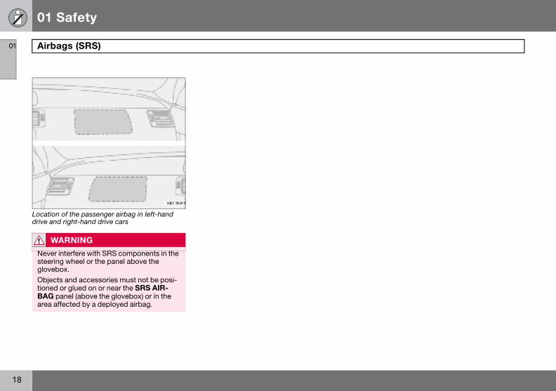
Locationdrive and
W
Never steeringlovebObjecttionedBAG parea af
gs (SRS)
of the passenger airbag in left-hand right-hand drive cars
ARNING
interfere with SRS components in the g wheel or the panel above the ox.s and accessories must not be posi- or glued on or near the SRS AIR-anel (above the glovebox) or in the fected by a deployed airbag.
01 Safety
19
ing/deactivating the airbag (SRS) 01
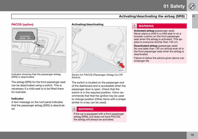
PACOS
Indicator(SRS) is
The airbcan be dnecessafor exam
IndicatA text mthat the ed.
WARNING
Activated airbag (passenger seat): Never place a child in a child seat or on a booster cushion on the front passenger seat when the airbag is activated. This ap-plies to everyone shorter than 140 cm.Deactivated airbag (passenger seat): No one taller than 140 cm should ever sit in the front passenger seat when the airbag is deactivated.Failure to follow the advice given above can endanger life.
Activat
(option)
showing that the passenger airbag deactivated.
ag (SRS) for the front passenger seat eactivated using a switch. This is ry if a child seat is to be fitted there ple.
oressage on the roof panel indicates passenger airbag (SRS) is deactivat-
Activating/deactivating
Switch for PACOS (Passenger Airbag Cut Off Switch).
The switch is located on the passenger end of the dashboard and is accessible when the passenger door is open. Check that the switch is in the required position. Volvo rec-ommends that that the ignition key be used to change position (Other items with a shape similar to a key can be used).
WARNING
If the car is equipped with a front passenger airbag (SRS), but does not have PACOS, the airbag will always be activated.

01 Safety
20
Activ01
Switch
Switch fo
ON = Aiin this pcan sit ichildrenion.
ating/deactivating the airbag (SRS)
position
r SRS in ON position.
rbag (SRS) activated. With the switch osition, persons taller than 140 cm n the front passenger seat, but never in a child seat or on a booster cush-
Switch for SRS in OFF position.
OFF = Airbag (SRS) is deactivated. With the switch in this position, children in a child seat or on a booster cushion can sit in the front passenger seat, but never persons taller than 140 cm.
WARNING
Do not allow anyone to sit in the front pas-senger seat if the text message in the roof panel indicates that the airbag (SRS) is de-activated and if the warning symbol for the AIRBAG system is also displayed on the combined instrument panel. This indicates that there has been a severe malfunction. Visit an authorised Volvo workshop urgent-ly.
01 Safety
21
Side airbags (SIPS bags) 01
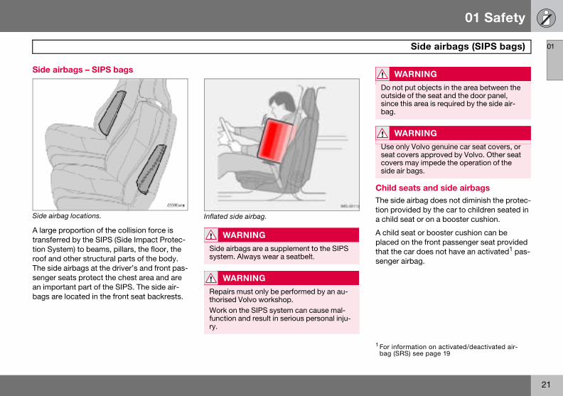
Side ai
Side airb
A large ptransfertion Sysroof andThe sidesenger san impobags are
Child seats and side airbagsThe side airbag does not diminish the protec-tion provided by the car to children seated in a child seat or on a booster cushion.
A child seat or booster cushion can be placed on the front passenger seat provided that the car does not have an activated1 pas-senger airbag.
WARNING
Do not put objects in the area between the outside of the seat and the door panel, since this area is required by the side air-bag.
WARNING
Use only Volvo genuine car seat covers, or seat covers approved by Volvo. Other seat covers may impede the operation of the side air bags.
1 For information on activated/deactivated air-bag (SRS) see page 19
rbags – SIPS bags
ag locations.
roportion of the collision force is red by the SIPS (Side Impact Protec-tem) to beams, pillars, the floor, the other structural parts of the body. airbags at the driver’s and front pas-eats protect the chest area and are rtant part of the SIPS. The side air- located in the front seat backrests.
Inflated side airbag.
WARNING
Side airbags are a supplement to the SIPS system. Always wear a seatbelt.
WARNING
Repairs must only be performed by an au-thorised Volvo workshop.Work on the SIPS system can cause mal-function and result in serious personal inju-ry.

01 Safety
22
Side 01
SIPS b
Driver’s
The SIPbags ansion tripare inflaoccupancushionThe sidethe side
airbags (SIPS bags)
ags
side
S bag system consists of side air-d sensors. A sufficiently violent colli-s the sensors and the side airbags ted. The airbag inflates between the t and the door panel and thereby
s the initial impact while deflating. airbag is normally only deployed on of the collision.
Passenger side
01 Safety
23
Inflatable Curtain (IC) 01
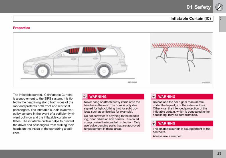
Proper
The inflais a supted in throof andpassenged by seolent coflates. Tthe driveheads osion.
WARNING
Do not load the car higher than 50 mm under the top edge of the side windows. Otherwise, the intended protection of the inflatable curtain, which is concealed in the headlining, may be compromised.
WARNING
The inflatable curtain is a supplement to the seatbelts.Always use a seatbelt.
ties
table curtain, IC (Inflatable Curtain), plement to the SIPS system. It is fit-e headlining along both sides of the protects both front and rear seat ers. The inflatable curtain is activat-nsors in the event of a sufficiently vi-llision and the inflatable curtain in-he inflatable curtain helps to prevent r and passengers from striking their
n the inside of the car during a colli-
WARNING
Never hang or attach heavy items onto the handles in the roof. The hook is only de-signed for light clothing (not for solid ob-jects such as umbrellas for example).Do not screw or fit anything to the headlin-ing, door pillars or side panels. This could compromise the intended protection. Only use Volvo genuine parts that are approved for placement in these areas.

01 Safety
24
WHIP01
ProtecWHIPS
The whiconsistsspeciallyfront seaend collthe collivehicle a
WHIPS system and child seats/booster cushions The WHIPS system does not diminish the protection provided by the car to children seated in a child seat or on a booster cush-ion.
Correct seating positionFor the best possible protection, the driver and front seat passenger should sit in the centre of the seat with as little space as pos-sible between the head and the head re-straint.
W
The Wseatbe
S
tion against whiplash injury –
plash protection system (WHIPS) of energy absorbing backrests and designed head restraints for the ts. The system is actuated by a rear-
ision, where the angle and speed of sion, and the nature of the colliding ll have an influence.
Properties of the seatWhen the WHIPS system is deployed, the front seat backrests fall backward to alter the position of the driver and front seat passen-ger. This diminishes the risk of whiplash inju-ry.
ARNING
HIPS system is a supplement to the lts. Always wear your seatbelt.
WARNING
Never modify or repair the seat or WHIPS system yourself. Contact an authorised Volvo workshop.
01 Safety
25
WHIPS 01
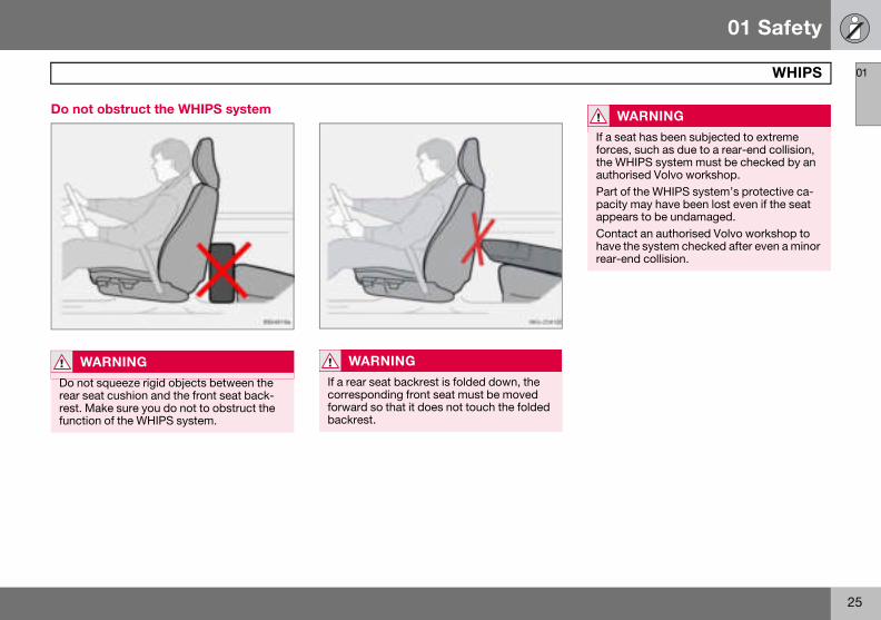
Do not
W
Do notrear serest. Mfunctio
WARNING
If a seat has been subjected to extreme forces, such as due to a rear-end collision, the WHIPS system must be checked by an authorised Volvo workshop.Part of the WHIPS system’s protective ca-pacity may have been lost even if the seat appears to be undamaged.Contact an authorised Volvo workshop to have the system checked after even a minor rear-end collision.
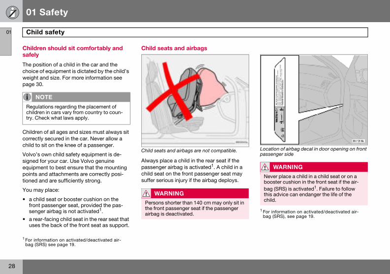
obstruct the WHIPS system
ARNING
squeeze rigid objects between the at cushion and the front seat back-ake sure you do not to obstruct the n of the WHIPS system.
WARNING
If a rear seat backrest is folded down, the corresponding front seat must be moved forward so that it does not touch the folded backrest.
01 Safety
26
When01
If the airlowing i
• HaveVolvoploye
• Let acomp
• Alwa
Syste
Seatbe nd/or overturning.Airbags
Side ai
Inflatab
Whipla
1The bo such as the rigidity and weight of the object hit, the speed
NO
The SRtems asion
WARNING
Never drive with deployed airbags. They can make steering difficult. Other safety systems may also be damaged. The smoke and dust created when the airbags are de-ployed can cause skin and eye irritation after intensive exposure. In case of irrita-tion, wash with cold water. The rapid de-ployment sequence and airbag fabric may cause friction and skin burns.
the systems deploy
bags have been deployed, the fol-s recommended:
the car transported to an authorised workshop. Do not drive with de-d airbags.n authorised Volvo workshop replace onents in the car’s safety system.
ys contact a doctor.
m Triggered
lt tensioner In a frontal collision and/or side-impact accident a (SRS) In a frontal collision1.
rbags (SIPS) In a side-impact accident1.le Curtain IC In a side-impact accident1.sh protection WHIPS In a rear-end collision.
dywork of the car could be greatly deformed in a collision without airbag deployment. A number of factors of the car, the angle of the collision etc. affects how the different safety systems of the car are activated.
TE
S, SIPS, IC and belt tensioner sys-re deployed only once during a colli-
WARNING
The AIRBAG control module is located in the centre console. If the centre console is drenched with water or other liquid, discon-nect the battery cables. Do not attempt to start the car since the airbags may deploy. Have the car transported to an authorised Volvo workshop.
01 Safety
27
Crash mode 01
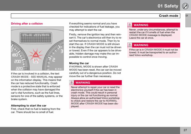
Driving
If the caCRASHon the inthe car hmode iswhen thcar’s vitsensorsbrake sy
AttempFirst, chcar. The
WARNING
Never, under any circumstances, attempt to restart the car if it smells of fuel when the CRASH MODE message is displayed. Leave the car at once.
WARNING
If the car is in CRASH MODE it must not be towed. It must be transported to an author-ised Volvo workshop.
after a collision
r is involved in a collision, the text MODE - SEE MANUAL may appear formation display. This means that as reduced functionality. Crash
a protective state that is enforced e collision may have damaged the al functions, such as the fuel lines, for one of the safety systems, or the stem.
ting to start the careck that no fuel is leaking from the re should be no smell of fuel.
If everything seems normal and you have checked for indications of fuel leakage, you may attempt to start the car.
Firstly, remove the ignition key and then rein-sert it. The car’s electronics will then try to re-set themselves to normal mode. Then try to start the car. If CRASH MODE is still shown in the display then the car must not be driven or towed. Even if the car appears to be drive-able, hidden damage may make the car im-possible to control once moving.
Moving the carIf NORMAL MODE is shown after CRASH MODE has been reset, the car can be moved carefully out of a dangerous position. Do not move the car further than necessary.
WARNING
Never attempt to repair your car or reset the electronics yourself if the car has been in crash mode. This could result in personal injury or the car not functioning as normal. Always allow an authorised Volvo workshop to check and restore the car to NORMAL MODE after CRASH MODE has been dis-played.
01 Safety
28
Child01
Childresafely
The poschoice oweight apage 30
Childrencorrectlchild to
Volvo’s signed fequipmepoints ationed a
You ma
• a chilfront seng
• a rearuses
Location of airbag decal in door opening on front passenger side
NO
Regulachildretry. Ch
1 For infobag (SR
WARNING
Never place a child in a child seat or on a booster cushion in the front seat if the air-bag (SRS) is activated1. Failure to follow this advice can endanger the life of the child.
1 For information on activated/deactivated air-bag (SRS), see page 19.
safety
n should sit comfortably and
ition of a child in the car and the f equipment is dictated by the child’s nd size. For more information see .
of all ages and sizes must always sit y secured in the car. Never allow a sit on the knee of a passenger.
own child safety equipment is de-or your car. Use Volvo genuine nt to best ensure that the mounting
nd attachments are correctly posi-nd are sufficiently strong.
y place:
d seat or booster cushion on the passenger seat, provided the pas-er airbag is not activated1.-facing child seat in the rear seat that the back of the front seat as support.
Child seats and airbags
Child seats and airbags are not compatible.
Always place a child in the rear seat if the passenger airbag is activated1. A child in a child seat on the front passenger seat may suffer serious injury if the airbag deploys.
TE
tions regarding the placement of n in cars vary from country to coun-eck what laws apply.
rmation on activated/deactivated air-S) see page 19.
WARNING
Persons shorter than 140 cm may only sit in the front passenger seat if the passenger airbag is deactivated.
01 Safety
29
Child safety 01
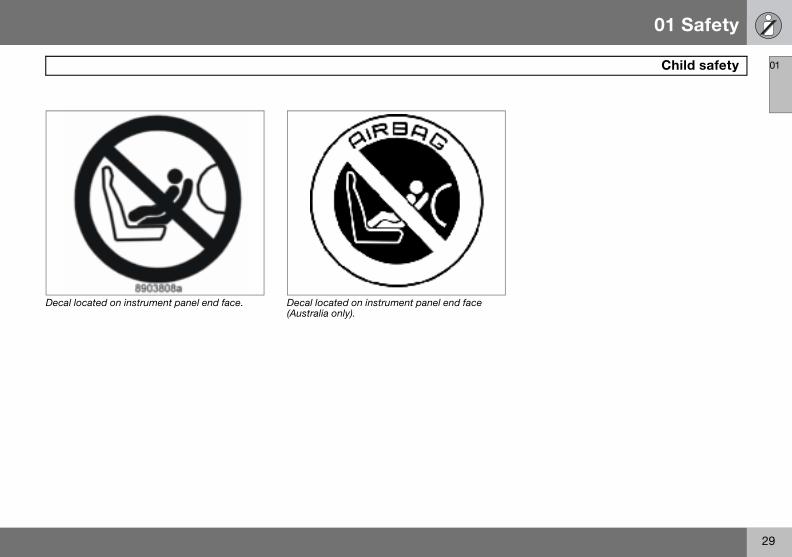
Decal loc
ated on instrument panel end face. Decal located on instrument panel end face (Australia only).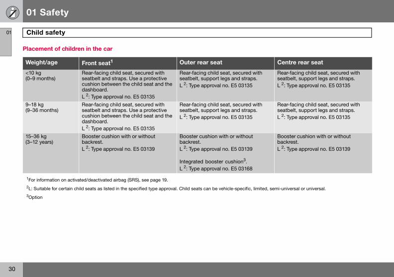
01 Safety
30
Child01
Placem
Weigh Centre rear seat
<10 kg(0–9 m
Rear-facing child seat, secured with seatbelt, support legs and straps. L 2: Type approval no. E5 03135
9–18 kg(9–36 m
Rear-facing child seat, secured with seatbelt, support legs and straps. L 2: Type approval no. E5 03135
15–36 k(3–12 y
Booster cushion with or without backrest. L 2: Type approval no. E5 03139
1For inf2L: Suit ited, semi-universal or universal.3Option
safety
ent of children in the car
t/age Front seat1 Outer rear seat
onths)Rear-facing child seat, secured with seatbelt and straps. Use a protective cushion between the child seat and the dashboard. L 2: Type approval no. E5 03135
Rear-facing child seat, secured withseatbelt, support legs and straps. L 2: Type approval no. E5 03135
onths)Rear-facing child seat, secured with seatbelt and straps. Use a protective cushion between the child seat and the dashboard. L 2: Type approval no. E5 03135
Rear-facing child seat, secured withseatbelt, support legs and straps. L 2: Type approval no. E5 03135
gears)
Booster cushion with or without backrest. L 2: Type approval no. E5 03139
Booster cushion with or without backrest. L 2: Type approval no. E5 03139
Integrated booster cushion3. L 2: Type approval no. E5 03168
ormation on activated/deactivated airbag (SRS), see page 19.
able for certain child seats as listed in the specified type approval. Child seats can be vehicle-specific, lim
01 Safety
31
Child safety 01
Integra
Volvo’s outer revide optwith theion is aptween 1
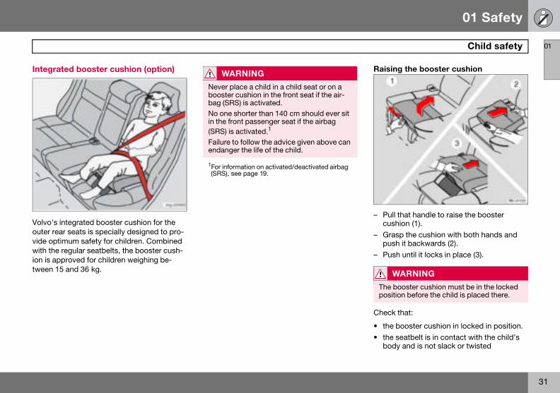
Raising the booster cushion
– Pull that handle to raise the booster cushion (1).
– Grasp the cushion with both hands and push it backwards (2).
– Push until it locks in place (3).
Check that:
• the booster cushion in locked in position.• the seatbelt is in contact with the child’s
body and is not slack or twisted
WARNING
The booster cushion must be in the locked position before the child is placed there.
ted booster cushion (option)
integrated booster cushion for the ar seats is specially designed to pro-imum safety for children. Combined regular seatbelts, the booster cush-proved for children weighing be-5 and 36 kg.
WARNING
Never place a child in a child seat or on a booster cushion in the front seat if the air-bag (SRS) is activated.No one shorter than 140 cm should ever sit in the front passenger seat if the airbag (SRS) is activated.1
Failure to follow the advice given above can endanger the life of the child.
1For information on activated/deactivated airbag (SRS), see page 19.
01 Safety
32
Child01
• the sebodythe bshou
• the hoptim
• the sethroa
• Carefrestra
W
RepairformedDo notto the bIf an insubjecjunctiocushioboosteit may tion. Thplaced
safety
atbelt is in contact with the child’s and is not slack or twisted, and that elt is positioned correctly across the lder.ip strap is low across the hips for um protection.atbelt does not lie across the child’s
t or below the shoulderully adjust the position of the head int to suit the child.
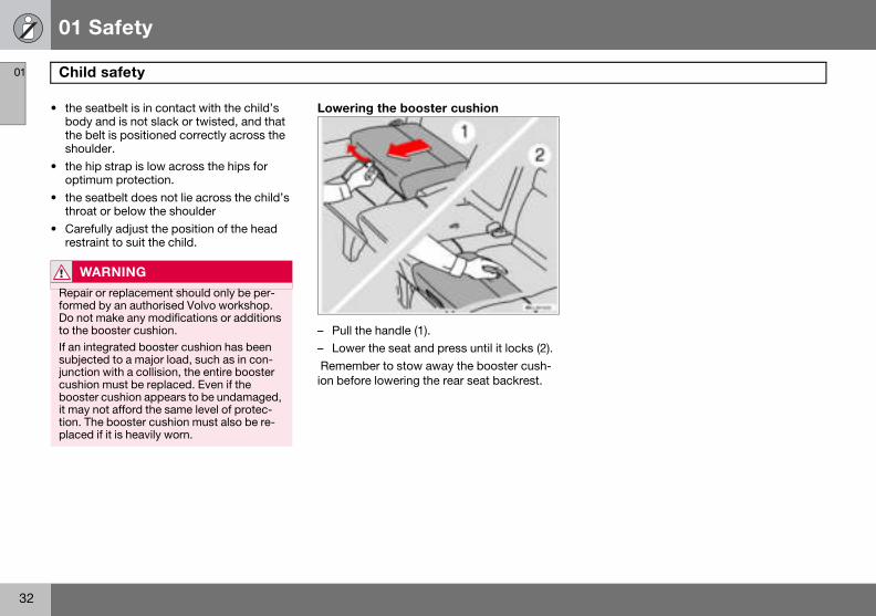
Lowering the booster cushion
– Pull the handle (1).– Lower the seat and press until it locks (2). Remember to stow away the booster cush-ion before lowering the rear seat backrest.
ARNING
or replacement should only be per- by an authorised Volvo workshop. make any modifications or additions ooster cushion.
tegrated booster cushion has been ted to a major load, such as in con-n with a collision, the entire booster n must be replaced. Even if the r cushion appears to be undamaged, not afford the same level of protec-e booster cushion must also be re-
if it is heavily worn.
01 Safety
33
Child safety 01
Fitting
Volvo hasigned f
When uable on installatproduct
• Do noto therails oedge
• Allowagaincars wthe a
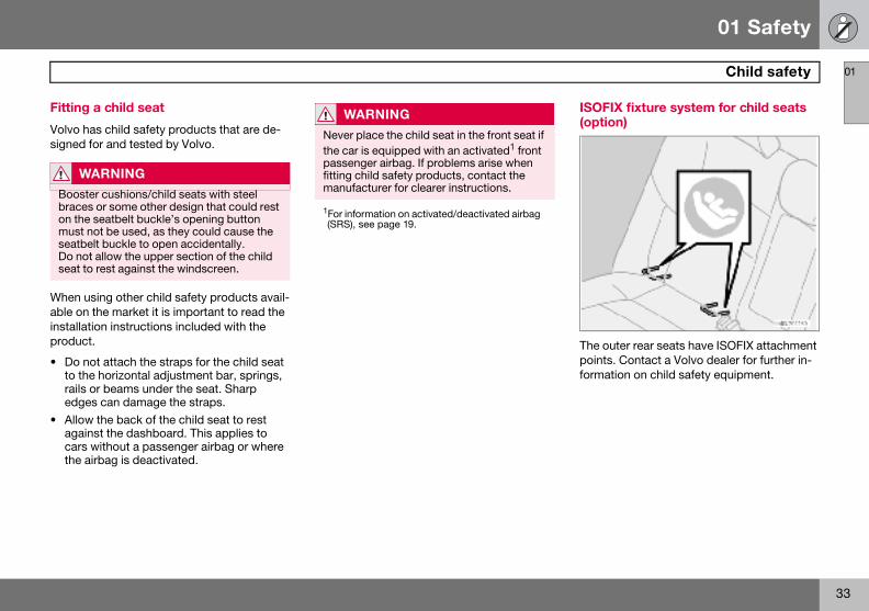
ISOFIX fixture system for child seats (option)
The outer rear seats have ISOFIX attachment points. Contact a Volvo dealer for further in-formation on child safety equipment.
W
Boostebraceson the must nseatbeDo notseat to
a child seat
s child safety products that are de-or and tested by Volvo.
sing other child safety products avail-the market it is important to read the ion instructions included with the .
t attach the straps for the child seat horizontal adjustment bar, springs, r beams under the seat. Sharp
s can damage the straps. the back of the child seat to rest st the dashboard. This applies to ithout a passenger airbag or where
irbag is deactivated.
ARNING
r cushions/child seats with steel or some other design that could rest seatbelt buckle’s opening button ot be used, as they could cause the lt buckle to open accidentally. allow the upper section of the child rest against the windscreen.
WARNING
Never place the child seat in the front seat if the car is equipped with an activated1 front passenger airbag. If problems arise when fitting child safety products, contact the manufacturer for clearer instructions.
1For information on activated/deactivated airbag (SRS), see page 19.
34
Overview, left-hand drive cars.................................................................. 36Overview, right-hand drive cars ............................................................... 38Driver’s door control panel....................................................................... 40Combined instrument panel .....................................................................41Indicator and warning symbols................................................................ 42Information display................................................................................... 47Electrical socket and switches on centre console ................................... 48Lighting panel........................................................................................... 49Left-hand stalk switch.............................................................................. 51Right-hand stalk switch ........................................................................... 53Cruise control (option).............................................................................. 55Steering wheel keypad (option)................................................................ 57Steering wheel adjustment, hazard warning flashers .............................. 58Parking brake, electrical socket ............................................................... 59Power windows ........................................................................................ 60Rearview and door mirrors....................................................................... 62Power sunroof (option) ............................................................................. 66Personal preferences ............................................................................... 68
02INSTRUMENTS AND CONTROLS
02 Instruments and controls
36
Over
02
view, left-hand drive cars
02 Instruments and controls
37
Overview, left-hand drive cars
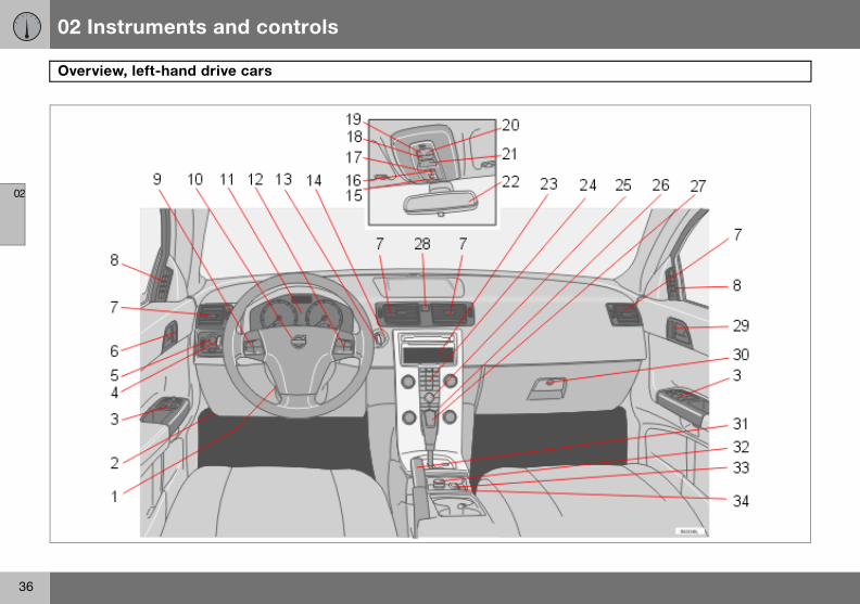
1. Stee2. Bon3. Con4. Dire5. Ligh6. Doo7. Air v8. Air v9. Crui10.Horn11.Com12.Keyp13.Wind14. Ignit15.Sun16.No f17.Dea18.Swit19.Rea20.Rea21.Seat22. Inter23.Disp24. Infot25.Con
pref
hers
garette lighterion System, BLISuipment
ring wheel adjustmentnet releasetrol panelction indicators, main beam, trip computerting, fuel filler flap openerr handle, lock button.ents in dashboardent for side windowse control, airbagbined instrument panelad for infotainment systemscreen wipers and washer, headlamp washers
ion switchroof controlsunctionctivation of alarm detectors, deadlocksch for interior lightingding lamp, left-hand sideding lamp, right-hand sidebelt reminderior rearview mirrorlay for climate control and infotainment systemainment systemtrols for climate control, infotainment system and personal erences
26.Climate control27.Gear lever28.Hazard warning flas29.Door handle30.Glovebox31.Parking brake32.Electrical socket/ci33.Blind Spot Informat34.Switch, optional eq
02 Instruments and controls
38
Over
02
view, right-hand drive cars

02 Instruments and controls
39
Overview, right-hand drive cars
1. Swit2. Blind3. Elec4. Park5. Con6. Glov7. Doo8. Air v9. Air v10.Gea11.Clim12.Con
pref13. Infot14.Disp15. Inter16.Seat17.Swit18.Rea19.Rea20.No f21.Dea22.Sun23. Ignit24.Wind25.Crui
nt panel
ment systemhersuttonlap opener, main beam, trip computer
stment
ch, optional equipment Spot Information System, BLIS
trical socket, cigarette lightering braketrol paneleboxr handleent for side windowents in dashboardr leverate controltrols for climate control, infotainment system and personal erences ainment systemlay for climate control and infotainment systemior rearview mirrorbelt reminderch for interior lightingding lamp, left-hand sideding lamp, right-hand sideunctionctivation of alarm detectors, deadlocksroof controlsion switchscreen wipers and washers, headlamp washers
se control
26.Combined instrume27.Horn, airbag28.Keypad for infotain29.Hazard warning flas30.Door handle, lock b31.Lighting, fuel filler f32.Direction indicators33.Bonnet release34.Steering wheel adju

02 Instruments and controls
40
Drive
02
Driver’
1. Bloc(stan
2. Pow3. Doo4. Doo5. Doo
r’s door control panel
s door control panel
king switch for rear power windows dard) Electric child locks (option)er windowsr mirror, left-hand sider mirrors, settingr mirror, right-hand side
02 Instruments and controls
41
Combined instrument panel
02
1. Spee2. Dire3. War4. Infor
pressagetimebetwsymwarnperahighstati
5. Infor
12.Main beam indicator.13.Knob for clock – Turn the knob to
adjust the time. 14.Temperature gauge – Displays the tem-
perature of the engine cooling system. A message will appear on the display if the temperature becomes too high and the gauge goes into the red zone. Bear in mind that extra lights placed in front of the air intake, for example, reduce the cooling capacity at high outside temperatures and high engine loads.
15. Indicator and warning symbols.
dometer.ction indicators, left.ning symbol.mation display – The display ents information and warning mes-s, outside temperature and the . When the ambient temperature is een +2 �C and –5 �C, a snowflake
bol appears on the display. This s of icy roads. The outside tem-ture gauge may show a slightly reading after the car has been onary.mation symbol.
6. Direction indicator, right.7. Tachometer – Indicates engine speed
in thousands of revolutions per minute (rpm).
8. Indicator and warning symbols.9. Fuel gauge.10.Button for trip meter – Used to measure
short distances. Press the button to switch between trip meters T1 and T2. Press and hold (more than 2 seconds) to zero the active trip meter.
11.Display – Display for automatic gear position, rain sensor, odometer, trip meter and cruise control.
02 Instruments and controls
42
Indic
02
Functio
All indicwhen thbefore sbols arethe symbrake syhandbra
pending
– Read the information on the information display.
– Rectify the fault as instructed or contact an authorised Volvo workshop.
When one of the car’s systems does not behave as intended, the yellow information symbol il-luminates and a text appears in the information display. The
message text is cleared using the READ but-ton, see page 47, or disappears automatical-ly after two minutes.
The yellow information symbol can also illu-minate in conjunction with other symbols.
1 For certoil presvia disp
NOTE
When the message text TIME FOR REGULAR SERVICE is shown, the symbol lamp and message text are cleared using the READ button, or disappear automati-cally after two minutes.
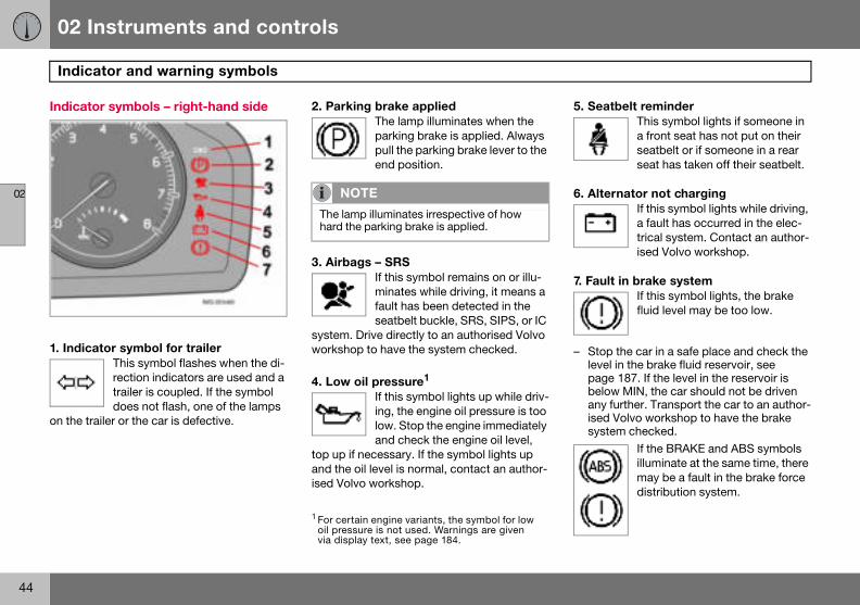
ator and warning symbols
nality check, symbols
ator and warning symbols1 illuminate e ignition key is turned to position II tarting. This is to check that the sym- working. When the engine starts, all bols should go out except the hand-mbol, which extinguishes when the ke is released.
If the engine does not start within five seconds, all sym-bols extinguish except the symbols for a fault in the car’s emissions system and for low oil pressure. Certain symbols may have no function, de-
on the car’s specifications.
Symbols in the centre of the instrument panel
The red warning symbol illumi-nates when a fault has been in-dicated which could affect the safety and/or driveability of the car. An explanatory text is
shown in the information display at the same time. The symbol and message text are visi-ble until the fault has been rectified.
The warning symbol can also illuminate in conjunction with other symbols.
– Stop in a safe place. Do not drive the car further.ain engine variants, the symbol for low
sure is not used. Warnings are given lay text, see page 184.

02 Instruments and controls
43
Indicator and warning symbols
02
Indicat
1. Fault
2. ABS
– Stop the e
or symbols – left-hand side
in car’s emissions system Drive to an authorised Volvo workshop to have the system checked.
fault If this symbol lights, the system is not working. The car’s regular brake system continues to work, but without the ABS function.
the car in a safe place and turn off ngine.
– Restart the engine.– Drive to an authorised Volvo workshop to
have the ABS checked if the symbol re-mains lit.
3. Rear fog lampThis symbol is lit when the rear fog lamp is on.
4. Stability system STC or DSTC For information on the system’s functions and symbols, see page 130.
5. No function
6. Engine preheater (diesel) This symbol is lit during engine preheating. Preheating occurs when the temperature is below –2 �C. The car can be started once the symbol extinguishes.
7. Low level in fuel tank This symbol lights when there are approximately 8 litres of usa-ble fuel left in a petrol-engined car, or approximately 7 litres in a diesel-engined car.
02 Instruments and controls
44
Indic
02
Indicat
1. Indic
on the tr
5. Seatbelt reminderThis symbol lights if someone in a front seat has not put on their seatbelt or if someone in a rear seat has taken off their seatbelt.
6. Alternator not chargingIf this symbol lights while driving, a fault has occurred in the elec-trical system. Contact an author-ised Volvo workshop.
7. Fault in brake systemIf this symbol lights, the brake fluid level may be too low.
– Stop the car in a safe place and check the level in the brake fluid reservoir, see page 187. If the level in the reservoir is below MIN, the car should not be driven any further. Transport the car to an author-ised Volvo workshop to have the brake system checked.
If the BRAKE and ABS symbols illuminate at the same time, there may be a fault in the brake force distribution system.
ator and warning symbols
or symbols – right-hand side
ator symbol for trailerThis symbol flashes when the di-rection indicators are used and a trailer is coupled. If the symbol does not flash, one of the lamps
ailer or the car is defective.
2. Parking brake applied The lamp illuminates when the parking brake is applied. Always pull the parking brake lever to the end position.
3. Airbags – SRSIf this symbol remains on or illu-minates while driving, it means a fault has been detected in the seatbelt buckle, SRS, SIPS, or IC
system. Drive directly to an authorised Volvo workshop to have the system checked.
4. Low oil pressure1 If this symbol lights up while driv-ing, the engine oil pressure is too low. Stop the engine immediately and check the engine oil level,
top up if necessary. If the symbol lights up and the oil level is normal, contact an author-ised Volvo workshop.
NOTE
The lamp illuminates irrespective of how hard the parking brake is applied.
1 For certain engine variants, the symbol for low oil pressure is not used. Warnings are given via display text, see page 184.

02 Instruments and controls
45
Indicator and warning symbols
02
– Stop the e
– Resta– If bot
ing.– If the
in the– If the
symbwith gworkchec
– If thethen furtheauthobrake
W
If the Bsame twill ski
the car in a safe place and turn off ngine.rt the engine.
h symbols extinguish, continue driv-
symbols remain on, check the level brake fluid reservoir. See page 187. brake fluid level is normal but the ols are still lit, the car can be driven, reat care, to an authorised Volvo
shop to have the brake system ked. level in the reservoir is below MIN the car should not be driven any r. Have the car transported to an rised Volvo workshop to have the system checked.
ARNING
RAKE and ABS symbols are lit at the ime, there is a risk that the rear end d during heavy braking.

02 Instruments and controls
46
Indic
02
Remind
If one ofis not prminded
Low sp
LEFT REor RIGHthe disppossible
High sp
graph a
Tailgat
1 Only ca
ator and warning symbols
er – doors not closed
the doors, the bonnet1 or the tailgate operly closed, the driver will be re-of this.
eed If the car moves at a speed less than approx. 7 km/h, the infor-mation symbol illuminates and DRIVER DOOR OPEN, PAS-SENGER DOOR OPEN,
AR DOOR OPEN, BONNET OPEN T REAR DOOR OPEN, is shown in lay. Stop the car safely as soon as and close the door or bonnet.
eedIf the car is moving faster than approx. 7 km/h, the symbol illu-minates and one of the texts in-dicated in the previous para-
ppears in the display.
e reminderIf the tailgate is open, this infor-mation symbol will illuminate and TAILGATE OPEN will appear on the display.
rs with alarms.
02 Instruments and controls
47
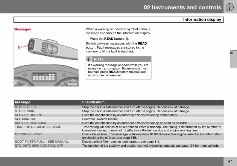
Information display
02
Messa
MessaSTOP S Serious risk of damage.STOP E Serious risk of damage.SERVIC p immediately.SEE MSERVIC p as soon as possible.TIME F op. The timing is determined by the number of
rvice and engine running time.CHECK 0 km (certain engine variants). For information
SOOT 9.STC/D is reduced, see page 131 for more variants.
ges When a warning or indicator symbol come, a message appears on the information display.
– Press the READ button (1).Switch between messages with the READ button. Fault messages are stored in the memory until the fault is rectified.
NOTE
If a warning message appears while you are using the trip computer, the message must be read (press READ) before the previous activity can be resumed.
ge SpecificationAFELY Stop the car in a safe manner and turn off the engine.NGINE Stop the car in a safe manner and turn off the engine.E URGENT Have the car checked by an authorised Volvo worksho
ANUAL Read the Owner’s Manual.E REQUIRED Have the car checked by an authorised Volvo worksho
OR REGULAR SERVICE Time for regular service at an authorised Volvo workshkilometres driven, number of months since the last se
OIL LEVEL Check the oil level. The message is shown every 10 00on checking the oil level, see page 185.
FILTER FULL – SEE MANUAL Diesel particle filter requires regeneration, see page 11STC SPIN CONTROL OFF The function of the stability and traction control system
02 Instruments and controls
48
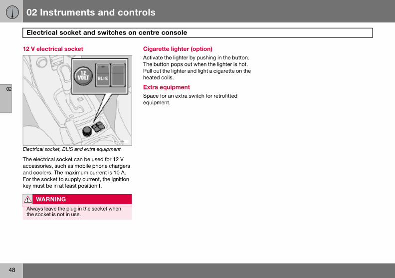
Elect
02
12 V el
Electrica
The elecaccessoand cooFor the key mus
W
Alwaysthe soc
rical socket and switches on centre console
ectrical socket
l socket, BLIS and extra equipment
trical socket can be used for 12 V ries, such as mobile phone chargers lers. The maximum current is 10 A. socket to supply current, the ignition t be in at least position I.
Cigarette lighter (option) Activate the lighter by pushing in the button. The button pops out when the lighter is hot. Pull out the lighter and light a cigarette on the heated coils.
Extra equipmentSpace for an extra switch for retrofitted equipment.
ARNING
leave the plug in the socket when ket is not in use.

02 Instruments and controls
49
Lighting panel
02
Headlamps
Automatic dipped beam (certain countries) Dipped beam comes on automatically when the ignition key is turned to position II , ex-cept when the headlamp control (2) is in the centre position. If necessary, the automatic dipped beam can be deactivated by an au-thorised Volvo workshop.
Automatic dipped beam, main beam – Turn the ignition key to position II.– Dipped beam is activated by means of
turning the headlamp control (2) clockwise to the end position.
– Main beam is activated by means of mov-ing the left-hand stalk switch towards the steering wheel to the end position and releasing it, see page 51.
The lamps are switched off automatically when the ignition key is turned to position I or 0.
Instrument lighting The instrument lighting is switched on when the ignition key is in position II and the head-lamp control (2) is in one of the end positions. The lighting is automatically dimmed during
Positi
Headlamp levellingThe load in the car changes the vertical align-ment of the headlamp beam, which could dazzle oncoming motorists. Avoid this by ad-justing the height of the beam.
– Turn the ignition key to position II.– Turn the headlamp control (2) to one of the
end positions.– Roll the control (1) up or down respective-
ly to raise or lower beam alignment.Cars with Bi-Xenon headlamps1 have auto-matic headlamp levelling, so there is no control (1).
Position/parking lamps Position/parking lamps can be switched on irrespective of ignition key position.
– Turn the headlamp control (2) to the centre position.
When the ignition key is in position II the po-sition/parking lamps and number plate light-ing are always on.
on Specification
Automatic/deactivated dipped beam. Only main beam flash.Position/parking lamps
Automatic dipped beam. Main beam and main beam flash work in this position.
1 Option.
02 Instruments and controls
50
Light
02
the day night.
– Roll tor dim
EnhancTo faciliclock anilluminathe key The displocked.
Fog lam
Front foThe fronalong wlamps/p
– PressThe lighthe fron
Rear foThe rearwith the
NO
Regulacountr
ing panel
and can be controlled manually at
he control up or down (3) for brighter mer lighting.
ed display lightingtate reading the odometer, trip meter, d outside temperature gauge, these
te when the car is unlocked and when is removed from the ignition switch. lays extinguish when the car is
ps
g lamps (option)t fog lamps can be switched on ith the headlamps or the position arking lamps.
the button (4).t in the button (4) illuminates when t fog lamps are switched on.
g lamp fog lamp can only be switched on headlamps or the front fog lamps.
– Press the button (6).The rear fog lamp indicator symbol on the combined instrument panel and the light in the button (6) illuminate when the rear fog lamp is switched on.
Fuel filler flapPress button (5) to open the fuel filler flap when the car is unlocked, see page 107.
TE
tions for use of fog lamps vary from y to country.
02 Instruments and controls
51
Left-hand stalk switch
02
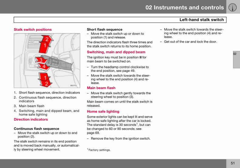
Stalk s
1. Shor2. Con
indic3. Main4. Swit
hom
Directi
Continu– Move
positThe staland is mly by ste
– Move the stalk switch towards the steer-ing wheel to the end position (4) and re-lease.
– Get out of the car and lock the door.
witch positions
t flash sequence, direction indicatorstinuous flash sequence, direction ators beam flashching, main and dipped beam, and e safe lighting
on indicators
ous flash sequence the stalk switch up or down to end
ion (2).k switch remains in its end position oved back manually, or automatical-ering wheel movement.
Short flash sequence– Move the stalk switch up or down to
position (1) and release.The direction indicators flash three times and the stalk switch returns to its home position.
Switching, main and dipped beam The ignition key must be in position II for main beam to be switched on.
– Turn the headlamp control clockwise to the end position, see page 49.
– Move the stalk switch towards the steer-ing wheel to the end position (4) and re-lease.
Main beam flash – Move the stalk switch gently towards the
steering wheel to position (3).Main beam comes on until the stalk switch is released.
Home safe lighting Some exterior lights can be kept lit and serve as home safe lighting after the car is locked. The standard delay is 30 seconds1, but can be changed to 60 or 90 seconds; see page 69.
– Remove the key from the ignition switch.
1 Factory settings.
02 Instruments and controls
52
Left-
02
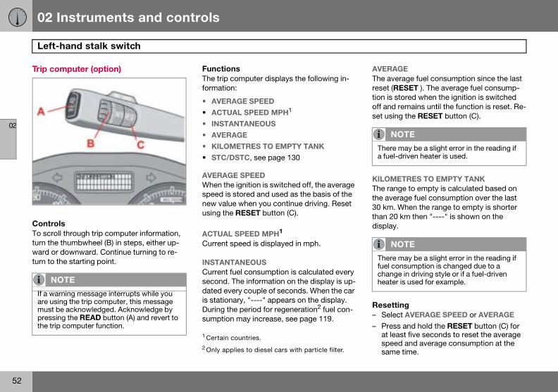
Trip co
ControTo scrolturn theward orturn to t
AVERAGE The average fuel consumption since the last reset (RESET ). The average fuel consump-tion is stored when the ignition is switched off and remains until the function is reset. Re-set using the RESET button (C).
KILOMETRES TO EMPTY TANKThe range to empty is calculated based on the average fuel consumption over the last 30 km. When the range to empty is shorter than 20 km then "----" is shown on the display.
Resetting– Select AVERAGE SPEED or AVERAGE
– Press and hold the RESET button (C) for at least five seconds to reset the average speed and average consumption at the same time.
NO
If a waare usimust bpressinthe trip
NOTE
There may be a slight error in the reading if a fuel-driven heater is used.
NOTE
There may be a slight error in the reading if fuel consumption is changed due to a change in driving style or if a fuel-driven heater is used for example.
hand stalk switch
mputer (option)
lsl through trip computer information, thumbwheel (B) in steps, either up- downward. Continue turning to re-he starting point.
FunctionsThe trip computer displays the following in-formation:
• AVERAGE SPEED
• ACTUAL SPEED MPH1
• INSTANTANEOUS
• AVERAGE
• KILOMETRES TO EMPTY TANK• STC/DSTC, see page 130
AVERAGE SPEEDWhen the ignition is switched off, the average speed is stored and used as the basis of the new value when you continue driving. Reset using the RESET button (C).
ACTUAL SPEED MPH1
Current speed is displayed in mph.
INSTANTANEOUS Current fuel consumption is calculated every second. The information on the display is up-dated every couple of seconds. When the car is stationary, "----" appears on the display. During the period for regeneration2 fuel con-sumption may increase, see page 119.
TE
rning message interrupts while you ng the trip computer, this message e acknowledged. Acknowledge by g the READ button (A) and revert to computer function.
1 Certain countries.2 Only applies to diesel cars with particle filter.
02 Instruments and controls
53
Right-hand stalk switch
02
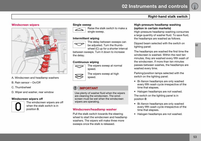
Windsc
A. Wind
B. Rain
C. Thum
D. Wipe
Windsc
High-pressure headlamp washing (option in certain markets)High-pressure headlamp washing consumes a large quantity of washer fluid. To save fluid, the headlamps are washed as follows.
Dipped beam selected with the switch on lighting panel:
The headlamps are washed the first time the windscreen is washed. Within the next ten minutes, they are washed every fifth wash of the windscreen. If more than ten minutes passes between washes, the headlamps are washed every time.
Parking/position lamps selected with the switch on the lighting panel:
• Bi-Xenon headlamps are only washed every fifth wash cycle irrespective of the time that elapses.
• Halogen headlamps are not washed.The switch on the lighting panel is in position 0:
• Bi-Xenon headlamps are only washed every fifth wash cycle irrespective of the time that elapses.
• Halogen headlamps are not washed.
reen wipers
screen and headlamp washers
sensor – On/Off
bwheel
r and washer, rear window
reen wipers offThe windscreen wipers are off when the stalk switch is in position 0.
Single sweepRaise the stalk switch to make a single sweep.
Intermittent wiping The delay between sweeps can be adjusted. Turn the thumb-wheel (C) up for a shorter interval
between sweeps. Turn it down to increase the delay.
Continuous wipingThe wipers sweep at normal speed.
The wipers sweep at high speed.
Windscreen/headlamp washer Pull the stalk switch towards the steering wheel to start the windscreen and headlamp washers. The wipers will make three more sweeps once the stalk is released.
IMPORTANT
Use plenty of washer fluid when the wipers are cleaning the windscreen. The wind-screen must be wet when the windscreen wipers are operating.
02 Instruments and controls
54
Righ
02
Rear wPress thwindowmakes sished. Tthree po
Intermit
– DeprNormal
– DeprNeutral:
– Func
Wiper –Engaginwipers adow wipready onmade.
The funcverse caised Vol
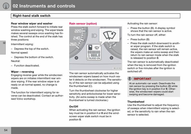
Activating the rain sensor:
– Press the button (B). A display symbol shows that the rain sensor is active.
To turn the rain sensor off, either:
– Press button (B)– Press the stalk switch downward to anoth-
er wiper program. If the stalk switch is raised, the rain sensor will remain active, the wipers make an extra sweep and then return to rain sensor mode when the stalk is released to position 0.
The rain sensor is automatically deactivated when the key is removed from the ignition switch or five minutes after the ignition is switched off.
ThumbwheelUse the thumbwheel to adjust the frequency of sweeps when intermittent wiping is select-ed, or the sensitivity to rain when the rain sensor is selected.
IMPORTANT
At an automatic car wash: Deactivate the rain sensor by pressing the button (B) while the ignition key is in position I or II. Other-wise, the windscreen wipers could start swiping and become damaged.
t-hand stalk switch
indow wiper and washer e stalk switch forward to initiate rear washing and wiping. The wiper blade everal sweeps once washing has fin-he control at the end of the stalk has sitions:
tent wiping:
ess the top of the switch.speed:
ess the bottom of the switch.
tion deactivated.
reversingg reverse gear while the windscreen re on initiates intermittent rear win-ing. If the rear window wiper is al- at normal speed, no change is
tion for intermittent wiping for re-n be deactivated. Contact an author-vo workshop.
Rain sensor (option)
The rain sensor automatically activates the windscreen wipers based on how much wa-ter it detects on the windscreen. The sensitiv-ity of the rain sensor can be adjusted using the thumbwheel (C).
Turn the thumbwheel clockwise for higher sensitivity and anticlockwise for lower sensi-tivity. (An extra sweep is made when the thumbwheel is turned clockwise.)
On/OffWhen activating the rain sensor, the ignition key must be in position I or II and the wind-screen wiper stalk switch must be in position 0.
02 Instruments and controls
55
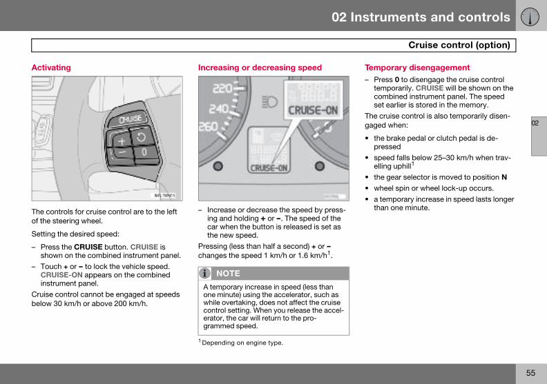
Cruise control (option)
02
Activat
The conof the st
Setting
– Pressshow
– ToucCRUIinstru
Cruise cbelow 3
Temporary disengagement– Press 0 to disengage the cruise control
temporarily. CRUISE will be shown on the combined instrument panel. The speed set earlier is stored in the memory.
The cruise control is also temporarily disen-gaged when:
• the brake pedal or clutch pedal is de-pressed
• speed falls below 25–30 km/h when trav-elling uphill1
• the gear selector is moved to position N• wheel spin or wheel lock-up occurs.• a temporary increase in speed lasts longer
than one minute.
ing
trols for cruise control are to the left eering wheel.
the desired speed:
the CRUISE button. CRUISE is n on the combined instrument panel.h + or — to lock the vehicle speed. SE-ON appears on the combined ment panel.ontrol cannot be engaged at speeds 0 km/h or above 200 km/h.
Increasing or decreasing speed
– Increase or decrease the speed by press-ing and holding + or —. The speed of the car when the button is released is set as the new speed.
Pressing (less than half a second) + or — changes the speed 1 km/h or 1.6 km/h1.
NOTE
A temporary increase in speed (less than one minute) using the accelerator, such as while overtaking, does not affect the cruise control setting. When you release the accel-erator, the car will return to the pro-grammed speed.
1 Depending on engine type.
02 Instruments and controls
56
Cruis
02
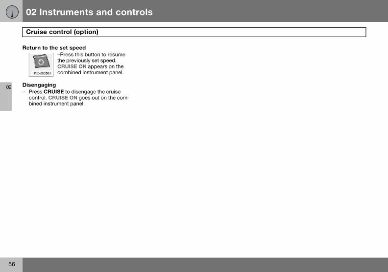
Return
Diseng– Press
contrbined
e control (option)
to the set speed–Press this button to resume the previously set speed. CRUISE ON appears on the combined instrument panel.
aging CRUISE to disengage the cruise ol. CRUISE ON goes out on the com- instrument panel.
02 Instruments and controls
57
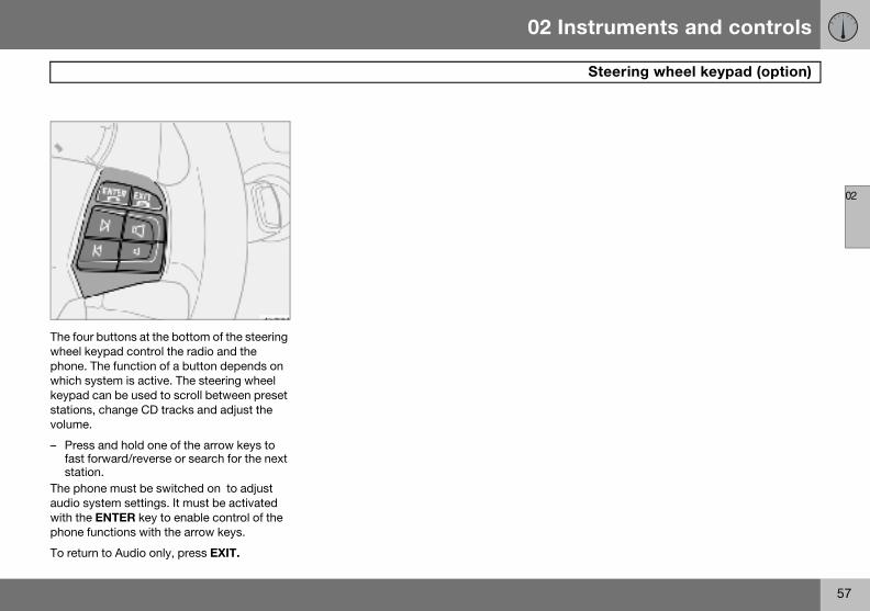
Steering wheel keypad (option)
02
The fourwheel kphone. Twhich skeypad stationsvolume.
– Pressfast fstatio
The phoaudio sywith thephone fu
To retur
buttons at the bottom of the steering eypad control the radio and the he function of a button depends on
ystem is active. The steering wheel can be used to scroll between preset , change CD tracks and adjust the
and hold one of the arrow keys to orward/reverse or search for the next n.ne must be switched on to adjust stem settings. It must be activated ENTER key to enable control of the nctions with the arrow keys.
n to Audio only, press EXIT.
02 Instruments and controls
58
Stee
02
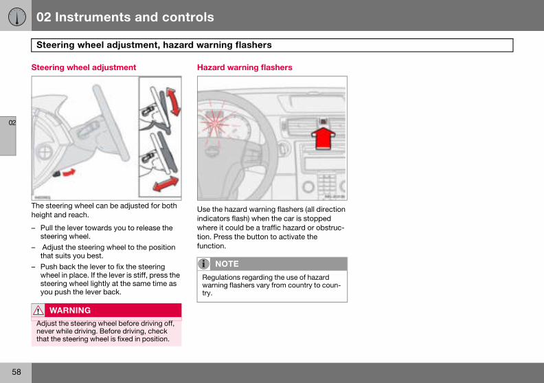
Steerin
The steeheight a
– Pull tsteer
– Adjuthat s
– Pushwheesteeryou p
W
Adjustnever wthat th
ring wheel adjustment, hazard warning flashers
g wheel adjustment
ring wheel can be adjusted for both nd reach.
he lever towards you to release the ing wheel.st the steering wheel to the position uits you best. back the lever to fix the steering l in place. If the lever is stiff, press the ing wheel lightly at the same time as ush the lever back.
Hazard warning flashers
Use the hazard warning flashers (all direction indicators flash) when the car is stopped where it could be a traffic hazard or obstruc-tion. Press the button to activate the function.
ARNING
the steering wheel before driving off, hile driving. Before driving, check
e steering wheel is fixed in position.
NOTE
Regulations regarding the use of hazard warning flashers vary from country to coun-try.
02 Instruments and controls
59
Parking brake, electrical socket
02
Parking
The leve
How to– Press– Pull u
full ex– Relea
sure
Electrical socket in the rear seat
The electrical socket can be used for 12 V accessories, such as mobile phone chargers and coolers. The maximum current is 10 A. For the socket to supply current, the ignition key must be in at least position I.
Cigarette lighter (option) Activate the lighter by pushing in the button. The button pops out when the lighter is hot. Pull out the lighter and light a cigarette on the heated coils.
NO
The wainstrumhow ha
WARNING
Always leave the plug in the socket when it is not in use.
brake (handbrake)
r is located between the front seats.
Apply the parking brake the foot brake pedal down firmly.p the parking brake lever firmly to its tent.se the foot brake pedal and make
that the car is at a standstill position.
– If the vehicle rolls, the parking brake lever must be pulled more firmly.
When parking a vehicle always put the gear selector in 1st gear (for manual transmission) or P (for automatic transmission).
Parking on a hillIf the car is parked facing uphill; turn the wheels away from the kerb.
If the car is parked facing downhill; turn the wheels toward the kerb.
How to release the parking brake– Press the foot brake pedal down firmly.– Pull the parking brake lever up slightly,
press the button, release the parking brake lever and release the button.
TE
rning lamp symbol in the combined ent panel illuminates irrespective of rd the parking brake is applied.
02 Instruments and controls
60
Powe
02
Operat
The powcontrolsbe in poto operaa limitedignition doors iscaution.
To open
– DeprTo close
– Raise
RemoteTo opertons andpage 10
window will then open or close automati-cally. If the window is obstructed by an object, the movement will stop.
W
Make sgers caclosingthe reathe driclosed
WARNING
The function that interrupts the movement of the windows in the event of blocking works with both automatic and manual closing, although not with pinch protection deployed.
WARNING
If there are children in the car:Remember to switch off the supply to the power windows by removing the ignition key if the driver leaves the car.Make sure that children and other passen-gers cannot be trapped in any way when closing the windows.
r windows
ion
er windows are operated using the in the doors. The ignition key must sition I and II for the power windows te. The windows continue to work for time when the car is stopped and key removed, provided none of the opened. Operate the windows with
a window:
ess the front of the control. a window:
the front of the control.
control and lock buttonsate the power windows with lock but- remote control, see page 100 and
8.
Driver’s door
Controls, power windows. A. Front B. Rear.
The driver can operate all of the power win-dows from the driver’s seat.
The windows can be opened and closed in two ways:
Manual operation– Depress one of the controls (A) or (B) gen-
tly or raise it gently. The power window opens or closes as long as the switch is actuated.
Automatic operation– Fully depress one of the controls (A) or (B)
or raise it fully, then release. The side
ARNING
ure that children and other passen-nnot be trapped in any way when the windows. Pay close attention if r door windows are controlled from ver’s door or if the windows are with the remote control.

02 Instruments and controls
61
Power windows
02
Blockindoors
Blockingsafety lo
The ligThe rearfrom the
The ligThe rearwith thethe cont
Rear power windows
The rear door windows can be operated with the control on each door or with the switch on the driver’s door. If the light in the switch for blocking the rear power windows (located in the control panel in the driver’s door) is lit, the rear door windows can only be operated from the driver’s door. The windows in the rear doors are operated in the same way as the windows in the front doors.
1Optio
g power windows in the rear
rear power windows and electric child cks1.
ht in the switch is lit door windows can only be operated driver’s door.
ht in the switch is extinguished door windows can be operated both control on each rear door and with rols on the driver’s door.
Front passenger seat
Front passenger seat
The control in the front passenger door oper-ates that window only.
n.
NOTE
If the car has electric child safety locks on the rear doors, the light indicates that these are activated. The doors then cannot be opened from the inside. A text message is shown on the display when the electric child safety locks are activated.
02 Instruments and controls
62
Rear
02
Interio
Bright lithe rearvdimminghind.
Dipping1. Con2. Norm3. Dim
AutomaBright lidimmed(1) is nodimming
Calibrating the compass
The earth is divided into 15 magnetic zones. The compass is set for the geographical area to which the car was delivered. The compass should be calibrated if the car is moved across several magnetic zones.
– Stop the car in a wide open area with the engine running at idling speed.
– Press and hold button (1) for at least 6 seconds. Following which, the sign C is shown (the button is concealed, so use a paper clip for example to press it in).
– Press and hold button (1) for at least 3 seconds. The number for the current magnetic zone is displayed.
view and door mirrors
r rearview mirror
ght from behind could be reflected in iew mirror and dazzle the driver. Use when disturbed by light from be-
trol for dimmingal position
med position.
tic dimming (option) ght from behind is automatically by the rearview mirror. The control t available in mirrors with automatic .
Rearview mirror with compass (option on certain markets)
The upper right-hand corner of the rearview mirror has an integrated display that shows the compass direction in which the front of the car is pointing. Eight different directions are shown with English abbreviations: N (north), NE (north east), E (east), SE (south east), S (south), SW (south west), W (west) and NW (north west).
02 Instruments and controls
63
Rearview and door mirrors
02
– Pressnumb15 ) iszones
– Wait the c
– Folloton fohand
– Drivespeetion iscates
Magnetic
Magnetic zones, Australia.
Magnetic zones, Africa.
the button (1) repeatedly until the er for the required magnetic zone (1– shown, refer to the map of magnetic for the compass.
until the display returns to showing haracter C.wing which, press and hold the but-r 9 seconds and select L for left-
drive cars and R for right-hand drive. slowly in a circle with a maximum d of 10 km/h until a compass direc- shown on the display, which indi- that the calibration is complete.
zones, Europe.
Magnetic zones, Asia.
Magnetic zones, South America.
02 Instruments and controls
64
Rear
02
Door m
The conrors arerest. Theignition
– PressmirroThe li
– Adjucentr
– Pressgoes
– Release the buttons. The mirrors automat-ically stop in the fully extended position.
Resetting to neutralMirrors that have been moved out of position by an external force must be reset to the neu-tral position for electric retracting and ex-tending to work.
– Press the L and R button to retract the mirrors.
– Extend the mirrors again with the L and R button. The mirrors are now reset to the neutral.
Home safe and approach lighting The light on the door mirrors (option) illumi-nates when the approach lighting or home safe lighting is activated.
Blind Spot Information System, BLIS (option)BLIS is an information system that under cer-tain conditions can help to draw the driver’s attention to vehicles moving in the same di-rection in the so-called "blind spot", see page 134.
view and door mirrors
irrors
trols for adjusting the two door mir- at the front of the driver’s door arm- rearview mirrors can be operated in
position I and II.
the L button for the left-hand door r or R for the right-hand door mirror. ght in the button lights.st the position with the joystick in the e. the L or R button again. The light
out.
Retractable power door mirrors (option) The mirrors can be retracted for parking and driving in narrow spaces. This can be done in ignition position I and II.
Retracting the mirrors– Press the L and R button at the same
time.– Release the buttons. The mirrors automat-
ically stop in the fully retracted position.
Folding out the mirrors– Press the L and R button at the same
time.
IMPORTANT
Do not use a scraper to remove ice from the mirrors as this could scratch the glass and the water and dirt-repellent coating1 could be damaged. Use the defroster function in-stead, see page 75.
1 Option
WARNING
The driver-side door mirror is wide angled to provide optimal vision. Objects may ap-pear further away than they actually are.
02 Instruments and controls
65
Rearview and door mirrors
02
Water a(optionThe doothat maithe rain.
In certaithe dirt-door mipage 75
Heat the
• If the• In hea• If the
nd dirt-repellent coating )r mirrors are treated with a coating ntains good rear-view vision despite
The mirrors treated with the water and dirt-repellent coating are marked with a small symbol. For informa-tion on how the mirrors should be maintained, see page 173.
n weather conditions, the function of repellent coating is improved if the rror defrosters are used, see or 78.
door mirrors:
y are covered with ice or snow.vy rain and dirty road conditions.
y are misted.
02 Instruments and controls
66
Powe
02
Open p
The sunpanel. Tsitions:
A. Venti
B. Slidin
The igni
From ventilation position to fully open sun-roof:
– Pull the control rearward to the end position (1) and release.
Sliding position
Automatic operation– Pull the control past the point of
resistance (2) to the rear end position (1) or past the point of resistance (3) to the forward end position (4) and release. The sunroof opens/closes completely.
Manual operation
Open:– Pull the control rearward to the point of
resistance (2). The sunroof moves toward the fully open position as long as the button is held in this position.
Close:– Press the control forward to the point of
resistance (3). The sunroof moves toward the closed position as long as the button is held in this position.
W
If thereSwitchby remleaves
WARNING
The sunroof’s pinch-protection function only operates during automatic closing, not manual closing.
r sunroof (option)
ositions
roof controls are located in the roof he sunroof can be opened to two po-
lation position, up at the rear edge
g position, backwards/forwards
tion key must be in position I or II.
1. Opening, automatic2. Opening, manual3. Closing, manual 4. Closing, automatic5. Opening, ventilation position6. Closing, ventilation position
Ventilation position
Open:– Press the rear edge of the control (5) up-
ward.Close:– Pull the rear edge of the control (6) down-
ward.
ARNING
are children in the car: off the supply to the power sunroof oving the ignition key if the driver the car.
02 Instruments and controls
67
Power sunroof (option)
02
Closingbutton
– Pressseconand t
If you ne
– Press
W
Make sare notwhen ccontrocaution
with remote control or lock
and hold the lock button for two ds. The sunroof and windows close
he doors lock.ed to interrupt closing:
the lock button again.
Sunscreen The sunroof features a manual, sliding interi-or sunscreen. The sunscreen slides back au-tomatically when the sunroof is opened. Grip the handle and slide the screen forwards to close it.
Pinch protection The sunroof’s pinch protection function is activated if the hatch is blocked by an object. If blocked, the sunroof will stop and automat-ically open to the previous position.
ARNING
ure that children or other passengers in danger of having hands trapped losing the sunroof with the remote
l. Always operate the sunroof with .
WARNING
The sunroof’s pinch protection function only operates during automatic closing, not during manual closing.Make sure children’s hands are clear when closing the sunroof.
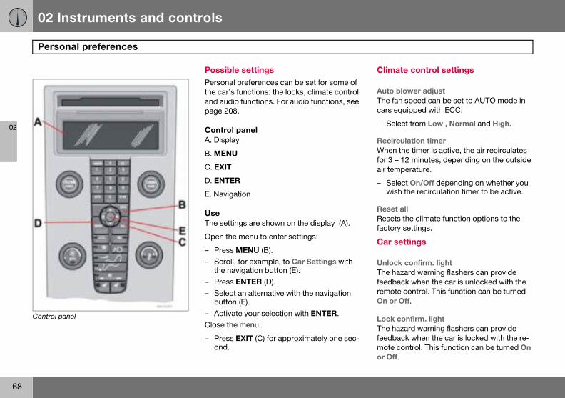
02 Instruments and controls
68
Pers
02
Control p
Climate control settings
Auto blower adjust The fan speed can be set to AUTO mode in cars equipped with ECC:
– Select from Low , Normal and High.
Recirculation timer When the timer is active, the air recirculates for 3 – 12 minutes, depending on the outside air temperature.
– Select On/Off depending on whether you wish the recirculation timer to be active.
Reset allResets the climate function options to the factory settings.
Car settings
Unlock confirm. light The hazard warning flashers can provide feedback when the car is unlocked with the remote control. This function can be turned On or Off.
Lock confirm. light The hazard warning flashers can provide feedback when the car is locked with the re-mote control. This function can be turned On or Off.
onal preferences
anel
Possible settingsPersonal preferences can be set for some of the car’s functions: the locks, climate control and audio functions. For audio functions, see page 208.
Control panelA. Display
B. MENU
C. EXIT
D. ENTER
E. Navigation
UseThe settings are shown on the display (A).
Open the menu to enter settings:
– Press MENU (B).– Scroll, for example, to Car Settings with
the navigation button (E).– Press ENTER (D).– Select an alternative with the navigation
button (E).– Activate your selection with ENTER.Close the menu:
– Press EXIT (C) for approximately one sec-ond.

02 Instruments and controls
69
Personal preferences
02
AutomaWhen ththe doomaticallOff. Pulland ope
Unlock There ar
• All dotrol u
• Drivepressdrivelocks
Keyless• All do
same• Door
doorssimul
• Bothunloc
• One f(eithe
ApproaSelect thon whenpressedable: 30
tic locking – doors e speed of the car exceeds 7 km/h
rs and tailgate can be locked auto-y. This function can be turned On/ing the door handle twice unlocks ns the doors from the inside.
doors e two alternatives for unlocking:
ors – one press of the remote con-nlocks both doors and the tailgate.r’s door first, then all others – one of the remote control unlocks the r’s door. A second press then un- all the other doors and the tailgate. entry (option in certain markets) ors – all doors are unlocked at the time.s on the same side – front and rear on the same side are unlocked taneously. front doors – both front doors are ked simultaneously.ront door – one of the front doors r) can be unlocked separately.ch lighting e time the car’s lights should remain the approach lighting button is . The following alternatives are avail-/60/90 seconds.
Home safe lighting Select the time the car’s lights should remain on when the left-hand stalk switch is pulled back after the ignition key has been re-moved. The following alternatives are availa-ble: 30/60/90 seconds.
Information• VIN (Vehicle Identification Number). The
car’s unique identity number.• Number of keys. The number of keys
registered for the car is shown.

70
General information on climate control ...................................................................................................... 72Manual climate control, A/C...................................................................... 74Electronic climate control, ECC (option) ..................................................................................................... 76Air distribution.......................................................................................... 79Fuel-driven heater (option ........................................................................ 80
03CLIMATE CONTROL
03 Climate control
72
Gene
03
Air conThe climand dehger comeither mcontrol (
MistingReduceon the inregular w
Ice andRemovetrol air inand the
Fault trEntrust control sshop on
• Fan speed in AUTO mode (applies only to cars with ECC).
• Recirculation timer for passenger com-partment air.
For information about these settings, see page 68.
NO
The airswitchble air prevenalways
ral information on climate control
ditioning ate control system cools or heats, umidifies the air entering the passen-partment. The car is equipped with anual (A/C ) or electronic climate ECC).
windows the problem of windows misting up side by cleaning the windows. Use a indow cleaner.
snow ice and snow from the climate con-take (the grille between the bonnet windscreen).
acing and repairfault tracing and repair of the climate ystem to an authorised Volvo work-ly.
Refrigerant The air conditioning system contains R134a refrigerant. This refrigerant contains no chlo-rine, which means that it is harmless to the ozone layer. The system must only be charged with R134a refrigerant. Have an au-thorised Volvo workshop carry out this work.
Passenger compartment filter All air which enters the passenger compart-ment is first cleaned by a filter. This filter must be replaced regularly. Follow the Volvo Service Programme for the recommended replacement intervals. If the car is used in a severely contaminated environment, it may be necessary to replace the filter more often.
DisplayThere is a display above the climate control panel that displays climate control settings.
Personal preferencesYou can set preferences for two climate con-trol functions:
TE
conditioning system can be ed off, but to ensure the best possi-in the passenger compartment and t the windows from misting, it should be on.
NOTE
There are several different types of passen-ger compartment filter. Ensure that the cor-rect filter is installed.
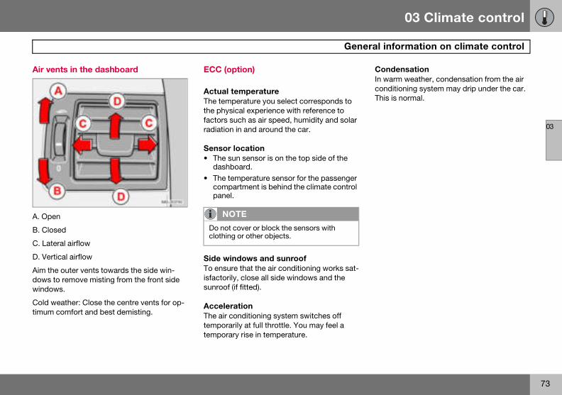
03 Climate control
73
al information on climate control
03
Air ven
A. Open
B. Close
C. Later
D. Vertic
Aim thedows towindow
Cold wetimum c
CondensationIn warm weather, condensation from the air conditioning system may drip under the car. This is normal.
Gener
ts in the dashboard
d
al airflow
al airflow
outer vents towards the side win- remove misting from the front side s.
ather: Close the centre vents for op-omfort and best demisting.
ECC (option)
Actual temperatureThe temperature you select corresponds to the physical experience with reference to factors such as air speed, humidity and solar radiation in and around the car.
Sensor location• The sun sensor is on the top side of the
dashboard.• The temperature sensor for the passenger
compartment is behind the climate control panel.
Side windows and sunroofTo ensure that the air conditioning works sat-isfactorily, close all side windows and the sunroof (if fitted).
AccelerationThe air conditioning system switches off temporarily at full throttle. You may feel a temporary rise in temperature.
NOTE
Do not cover or block the sensors with clothing or other objects.
03 Climate control
74
Manu
03
Contro
1. Fan2. Rec3. Defr4. Air d5. AC O6. Hea7. Hea8. Rea
ers9. Tem
2. Recirculation Recirculation can be used to shut out bad air, exhaust fumes, etc. from the pas-senger compartment. The air in the passenger com-partment is recirculated. No outside air is taken into the
car when this function is activated. Recircu-lation (together with the air conditioning sys-tem ) cools the passenger compartment more quickly in hot weather. If the air in the car recirculates for too long, there is a risk of the windows misting.
al climate control, A/C
l panel
irculationosteristributionN/OFF
ted front left seatted front right seatr window and door mirror defrost-
perature
Functions
1. Fan Increase or decrease the fan speed by turning the knob.
If the knob is turned anti-clockwise and the fan indi-cator in the display goes out, the fan and the air con-
ditioning are switched off. The display shows the fan symbol and OFF.
03 Climate control
75
Manual climate control, A/C
03
Timer The timemisting ed. Seevate thegram is
3. Defro
The follofroster fvide masenger c
• the aswitcA/C b
• recircWhen thmate co
– Lower heat Press the button twice – one light illumi-nates.
– Heat off Press the button three times – light not illuminated.
8. Rear window and door mirror defrosters
Heating is used to quickly remove misting and ice from the rear window and door mirrors.
The rear window and door mirrors are defrosted simul-
taneously if the switch is pressed once. The function is active if one light is lit in the switch. The door mirror heating is deactivat-ed automatically after approximately 6 minutes. The rear window heating is deac-tivated after approximately 12 minutes.
9. Temperature Select cooling or heating for both driver and passenger side.
r function minimises the risk of icing, and bad air if recirculation is select- page 68, for how to activate/deacti- function. When the Defroster (3) pro-selected, recirculation is deactivated.
ster Quickly removes misting and ice from the wind-screen and side windows. Air flows to the windows at high fan speed. The light in the defroster button lights when the function is active.
wing also takes place when the de-unction is activated in order to pro-ximum dehumidification in the pas-ompartment:
ir conditioning (A/C) is automatically hed on (can be switched off with the utton (5)ulation is automatically disengaged.e defroster is switched off the cli-ntrol returns to the previous settings.
4. Air distributionThe airflow can be distribut-ed to the windows, dash-board vents or floor by pressing the air distribution buttons.
A symbol on the display above the climate control panel and an illumi-nated light in the relevant button indicate which function has been selected.
See the table on p. 79.
5. AC – ON/OFF ON : Air conditioning is on. It is controlled by the system’s AUTO function. This way, in-coming air is cooled and de-humidified.
OFF : Off.
When the defroster function is activated the air conditioning is automatically switched on (can be switched off with the A/C button).
6. and 7. Heated front seats (option in certain markets)
–Higher heat Press the button once – both lights illuminate.
03 Climate control
76
Elect
03
Contro
1. AUT2. Fan3. Rec4. Defr5. Air d6. A/C 7. Hea8. Hea9. Rea
ers10.Tem
. Fan Increase or decrease fan speed by turning the knob. The fan speed is regulated automatically if AUTO is se-lected, and the previously set fan speed is disen-gaged.
ronic climate control, ECC (option)
l panel
O
irculation/Air quality systemosteristribution– On/Off (ON/OFF)ted front left seatted front right seat
r window and door mirror defrost-
perature selector
Functions
1. AUTO The AUTO function auto-matically regulates climate control and maintains the selected temperature. The AUTO function controls heating, air conditioning, fan speed, recirculation, and air
distribution. If you select one or more manual functions, the other functions continue to be controlled automatically. All manual settings are switched off when AUTO is switched on. The display shows AUTO CLIMATE.
2
03 Climate control
77
nic climate control, ECC (option)
033. Reci
the car wair in thea risk ofdows.
Timer The timemisting ed. Seehow to a
• As a rule, the air quality sensor should always be engaged.
• Recirculation is limited in cold weather to avoid misting.
• If the insides of the windows start misting up, disengage the air quality sensor.
• The defroster function for the front, side and rear windows can also be used to demist the windows.
4. Defroster Quickly removes misting and ice from the wind-screen and side windows. Air flows to the windows at high fan speed. The light in the defroster button lights when the function is active.
The following also takes place when the de-froster function is activated in order to pro-vide maximum dehumidification in the pas-senger compartment:
• the air conditioning (A/C) is automatically switched on (can be switched off with the A/C button (5)
• recirculation is automatically disengaged.When the defroster is switched off the cli-mate control returns to the previous settings.
NO
If the kfan indfan andoff. ThOFF.
NO
When is alwa
Electro
rculation Recirculation can be used to shut out bad air, exhaust fumes, etc. from the pas-senger compartment. The air in the passenger com-partment is recirculated, i.e. no outside air is taken into
hen this function is activated. If the car recirculates for too long, there is misting on the insides of the win-
r function minimises the risk of icing, and bad air if recirculation is select- Personal preferences, page 68, for ctivate/deactivate the function.
3. Air quality system (option) (same button as recircula-tion)
The air quality system con-sists of a multi-filter and a sensor. The filter separates gases and particles to re-
duce the levels of odours and pollution in the passenger compartment. When the sensor detects polluted outside air, the air intakes are closed and the air in the passenger com-partment is recirculated. A green light (A) illu-minates in the button when the air quality sensor is active.
Activating the air quality sensor:
– Press AUTO (1) to activate the air quality sensor (normal setting).
Or:
– Switch between three functions by press-ing repeatedly the recirculation button.
• Air quality sensor engaged – the light (A) illuminates.
• No recirculation engaged, provided it is not required for cooling in hot weather – light not illuminated.
• Recirculation engaged – the light (M) illu-minates.
Keep the following in mind:
TE
nob is turned anticlockwise and the ication on the display goes out, the the air conditioning are switched
e display shows the fan symbol and
TE
Defroster (4) is selected, recirculation ys deactivated.
03 Climate control
78
Elect
03
5. Air d
above thnated ligwhich fu
See the
6. AC –
When thair cond(can be
7. and 8
again to activate the other side. Press the button a third time to activate both sides.
The active side is indicated by the button’s light and in the display above the climate control panel.
When the car is started, the most recent set-ting is resumed.
NOTE
Heating or cooling cannot be hastened by selecting a higher or lower temperature than the actual desired temperature.
ronic climate control, ECC (option)
istribution The airflow can be distribut-ed to the windows, dash-board vents or floor by pressing the air distribution buttons.
A symbol on the display e climate control panel and an illumi-ht in the relevant button indicate nction has been selected.
table on p. 79.
ON/OFF ON: Air conditioning is on. It is controlled by the sys-tem’s AUTO function. This way, incoming air is cooled and dehumidified.
OFF: Off.
e defroster function is activated the itioning is automatically switched on switched off with the A/C button).
. Heated front seats (option in certain markets)
To activate front seat heat-ing:
– Higher heat: Press the button once – both lights illumi-nate.
– Lower heat: Press the button twice – one light illumi-nates.
– Heat off: Press the button three times – light not illuminated.
9. Rear window and door mirror defrosters
Heating is used to quickly remove misting and ice from the rear window and door mirrors.
The rear window and door mirrors are defrosted simul-
taneously if the switch is pressed once. The function is active if one light is lit in the switch. The door mirror heating is deactivat-ed automatically after approximately 6 minutes. The rear window heating is deac-tivated after approximately 12 minutes.
10. Temperature selector The temperatures on the driver and passenger sides can be set independently.
Press the button once to activate one side. Press

03 Climate control
79
Air distribution
03
tribution Use:
he floor and s. Some air flows ashboard air vents.
To ensure comfortable conditions and good demisting in cold or humid weather.
loor and from ard air vents.
In sunny weather with cool outside tempera-tures.
he floor. Some air o the dashboard air nd windows.
To warm the feet.
to windows, from ard air vents and to r.
To provide cooler air for the feet or warmer air to the upper body in cold weather or hot, dry weather.
Air distribution Use: Air dis
Air to windows. Some air flows to the dashboard air vents. The air is not recircu-lated. Air conditioning is always engaged.
To remove ice and misting quickly.
Air to twindowto the d
Air to windscreen and side windows. Some air flows to the dashboard air vents.
To prevent misting and icing in a cold and humid climate. (Not for low fan speed.)
Air to fdashbo
Airflow to windows and from dashboard air vents.
To ensure good comfort in warm, dry weather.
Air to tflows tvents a
Airflow to the head and chest from the dashboard air vents.
To ensure efficient cooling in warm weather.
Airflowdashbothe floo

03 Climate control
80
Fuel-
03
Genera
The parately or ing TIMEtime refeready. Twhen heoutside the outsminus 1ning tim
ParkingIf the cathe car sthere is heater.
Activating the heater
– Enter the time when the car is to be used. Press RESET (C) to enter the hours and minutes.
– Press and hold the RESET (C) button until the timer is activated.
Direct start– Use the thumbwheel (B) to scroll to DI-
RECT START.– Press RESET (C) to access the options
ON and OFF.– Select ON. The heater will now run for
60 minutes. Heating of the passenger compartment will begin as soon as the engine coolant has reached a temperature of 30 ºC.
W
The caor dies
W
SwitchfuellingCheckheaterrunninginform
driven heater (option)
l information about heaters
king heater can be started immedi-set with two different start times us-R AM and TIMER PM. Here, start rs to the time the car is heated and
he car’s electronic system calculates ating should be started based on the temperature. The heater is not run if ide temperature exceeds 25 �C. At 0 �C and below, the maximum run-e of the parking heater is 60 minutes.
on a hill r is parked on a steep hill, the front of hould point downhill to ensure that
a supply of fuel to the parking Warning decal on fuel filler flap.
ARNING
r must be outdoors when the petrol el heater is used.
ARNING
off the fuel-driven heater before re-. Spilled fuel could be ignited.
on the information display that the is off. When the additional heater is , PARK HEAT ON is shown on the
ation display.
03 Climate control
81
Fuel-driven heater (option)
03
Immed– Use t
RECT– Press
ON a– Selec
BatteryIf the bafuel leveswitchepears onedge theonce (A
Clock/timerIf the car clock is reset after the heater timers are programmed, the selected times will be cancelled.
Additional heater (diesel) (certain countries)
Extra heat from the additional heater may be required in cold weather to reach the correct temperature in the passenger compartment.
The additional heater starts automatically when extra heat is required if the engine is running. It is switched off automatically when the correct temperature is reached or when the engine is switched off.
NO
The caparking
IM
Repeabined wthe batis usedthe samthe altetery.
iate stop of heaterhe thumbwheel (B) to scroll to DI- START. RESET (C) to access the options nd OFF.t OFF.
and fuel ttery has insufficient charge or the l is too low, the parking heater will be d off automatically. A message ap- the information display. Acknowl- message by pressing READ
).
Setting the TIMER AM and PM For safety reasons, you can only programme times for the following 24 hours, not several days in advance.
– Scroll with the thumbwheel to TIMER.– Touch RESET to move to the flashing
hours setting.– Scroll with the thumbwheel to the desired
hour.– Touch RESET to move to the flashing
minutes setting.– Scroll with the thumbwheel to the desired
minute.– Touch RESET to confirm the setting.– Press RESET to activate the timer. After
setting TIMER AM , a second start time can be programmed with TIMER PM. Ac-cess this with the thumbwheel. Set the alternative start time in the same way as TIMER AM.
Messages on the displayWhen TIMER AM , TIMER PM and DIRECT START are activated, the information symbol on the combined instrument panel lights and an explanatory text appears on the informa-tion display. The display also indicates which TIMER is active when the driver removes the key from the ignition to leave the car.
TE
r can be started and driven while the heater is still running.
PORTANT
ted use of the parking heater com-ith short journeys may discharge
tery and impair starting. If the heater regularly, the car must be driven for e as the heater is run to ensure that
rnator has time to charge the bat-
82
Front seats ...............................................................................................84Interior lighting ......................................................................................... 86Storage spaces in the passenger compartment...................................... 88Rear seat .................................................................................................. 90Cargo area................................................................................................ 92
04INTERIOR
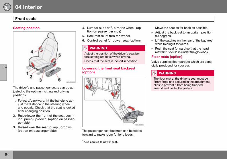
04 Interior
84
Fron
04
Seating
The drivjusted toposition
1. Forwjust and after
2. Raision, ger s
3. Rais(opt
– Move the seat as far back as possible.– Adjust the backrest to an upright position
90 degrees.– Lift the catches on the rear of the backrest
while folding it forwards.– Push the seat forward so that the head
restraint "locks" in under the glovebox.
Floor mats (option) Volvo supplies floor carpets which are espe-cially produced for your car.
WARNING
The floor mat at the driver’s seat must be firmly fitted and secured in the attachment clips to prevent it from being trapped around and under the pedals.
t seats
position
er’s and passenger seats can be ad- the optimum sitting and driving
s
ard/backward: lift the handle to ad-the distance to the steering wheel pedals. Check that the seat is locked changing position.e/lower the front of the seat cush-pump up/down, (option on passen-ide)
e/lower the seat, pump up/down, ion on passenger side)
4. Lumbar support1, turn the wheel, (op-tion on passenger side)
5. Backrest rake: turn the wheel.6. Control panel for power seat (option).
Lowering the front seat backrest (option)
The passenger seat backrest can be folded forward to make room for long loads.
1 Also applies to power seat.
WARNING
Adjust the position of the driver’s seat be-fore setting off, never while driving.Check that the seat is locked in position.
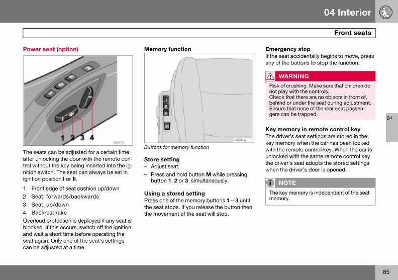
04 Interior
85
Front seats
04
Power
The seaafter untrol withnition swignition
1. Fron2. Seat3. Seat4. BacOverloablockedand waiseat agacan be a
Emergency stopIf the seat accidentally begins to move, press any of the buttons to stop the function.
Key memory in remote control key The driver’s seat settings are stored in the key memory when the car has been locked with the remote control key. When the car is unlocked with the same remote control key the driver’s seat adopts the stored settings when the driver’s door is opened.
WARNING
Risk of crushing. Make sure that children do not play with the controls. Check that there are no objects in front of, behind or under the seat during adjustment. Ensure that none of the rear seat passen-gers can be trapped.
NOTE
The key memory is independent of the seat memory.
seat (option)
ts can be adjusted for a certain time locking the door with the remote con-out the key being inserted into the ig-itch. The seat can always be set in
position I or II.
t edge of seat cushion up/down , forwards/backwards, up/down
krest raked protection is deployed if any seat is . If this occurs, switch off the ignition t a short time before operating the in. Only one of the seat’s settings djusted at a time.
Memory function
Buttons for memory function
Store setting– Adjust seat.– Press and hold button M while pressing
button 1, 2 or 3 simultaneously.
Using a stored settingPress one of the memory buttons 1 – 3 until the seat stops. If you release the button then the movement of the seat will stop.
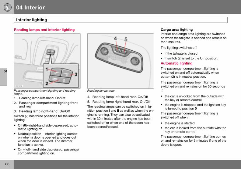
04 Interior
86
Inter
04
Readin
Passenglamps.1. Read2. Pass
and 3. ReaSwitch (lighting:
• Off (0matic
• Neutron whwhenfunct
• On – comp
Cargo area lighting Interior and cargo area lighting are switched on when the tailgate is opened and remain on for 5 minutes.
The lighting switches off:
• if the tailgate is closed• if switch (2) is set to the Off position.
Automatic lighting The passenger compartment lighting is switched on and off automatically when button (2) is in neutral position.
The passenger compartment lighting is switched on and remains on for 30 seconds if:
• the car is unlocked from the outside with the key or remote control
• the engine is stopped and the ignition key is turned to position 0
The passenger compartment lighting is switched off when:
• the engine is started.• the car is locked from the outside with the
key or remote controlThe passenger compartment lighting comes on and remains on for 5 minutes if one of the doors is open.
ior lighting
g lamps and interior lighting
er compartment lighting and reading
ing lamp left-hand, On/Offenger compartment lighting front rearding lamp right-hand, On/Off2) has three positions for the interior
)– right-hand side depressed, auto- lighting off.al position – interior lighting comes en a door is opened and goes out
the door is closed. The dimmer ion is active.left-hand side depressed, passenger artment lighting on.
Reading lamps, rear
4. Reading lamp left-hand rear, On/Off5. Reading lamp right-hand rear, On/OffThe reading lamps can be switched on in ig-nition position I and II as well as when the en-gine is running. They can also be activated within 30 minutes after the engine has been switched off or when one of the doors has been opened/closed.
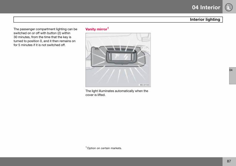
04 Interior
87
Interior lighting
04
The passwitche30 minuturned tfor 5 min
senger compartment lighting can be d on or off with button (2) within tes, from the time that the key is o position 0, and it then remains on utes if it is not switched off.
Vanity mirror1
The light illuminates automatically when the cover is lifted.
1 Option on certain markets.

04 Interior
88
Stora
04
ge spaces in the passenger compartment
04 Interior
89
s in the passenger compartment
04
Storag
1. Storfront
2. Com3. Tick4. Coa5. Glov6. Was7. Stor
disc8. Bott9. Stor
1 Storage
IM
The waphonehand s
W
Ensurelie or pcause Alwaysa seatb
Storage space
e spaces
age pocket (also on front edge of seat cushions).partment in door panel.et clip.t hanger, only for light garments.ebox.te bin (accessory).age compartment (e.g. for CD s) and cup holder1.le holder (option).age compartment and cup holder.
Glovebox
1. Unlocking2. LockingThe Owner’s Manual and maps can be kept here. There are also holders for coins, pens and fuel cards. The glovebox can be locked with the detachable key blade in the remote control. For further information on the key blade, see page 101.
compartment, in certain markets.
PORTANT
ste bin (6) must not be mounted if a handset is mounted on the right-ide of the centre console.
ARNING
that no hard, sharp or heavy objects rotrude in such a way that they could injury during heavy braking. secure large and heavy objects with elt or cargo retaining straps.
04 Interior
90
Rear
04
Head r
All headto suit thedge of with midthe headhead reshand pilthe headstraint, plar while
Tipping the rear seat backrest The rear seat backrests can be tipped for-wards together, or individually, to make it easier to transport long objects. To avoid damaging the seatbelts when folding the backrests up or down, these should be hooked onto the grab handles.
– Hang the seatbelts on the hooks before lowering or raising the backrests.
– Lift the rear edge of the seat cushion (1) to fold the seat cushions forward.
NOTE
When tipping the rear seat the safety plug for the 12 V socket should be removed and placed in the glovebox to avoid pressure marks in the upholstery.
seat
estraint, rear
restraints can be adjusted vertically e height of the passenger. The upper the head restraint should be aligned dle of the back of the head. Raise restraint as necessary. To lower the traint, press the button by the right-
lar at the same time as pushing down restraint. To remove the head re-ress the button by the right-hand pil- lifting out the head restraint.
IMPORTANT
The head restraints can be damaged if they are not removed for loading. The head re-straint in the centre must also be removed for heavy loads.
04 Interior
91
Rear seat
04
Lowering
– Pull treleathe lono lo
– Fold remoseatsmust
– Placesleevseat c
Bottle holder (option)
A bottle holder for larger bottles is located on the rear of the tunnel console.
the backrest
he lock (2) catch up and forward to se the backrest. A red indicator on ck catch shows that the backrest is
nger locked in place.the backrests (3) forward halfway and ve the head restraints on the outside . The centre seat’s head restraint be removed for a fully level floor. the head restraints in the plastic es on the undersides (4) of the raised ushions.
NOTE
When the backrest has been raised, the red indicator should no longer be showing. If it is, the backrest is not locked in place.
WARNING
Remember to take down the seatbelts once you have raised the backrest.
04 Interior
92
Carg
04
Safety
The safeloads orthe passsudden must alwcured.
FoldingIf the saed up to
– Takegrille.
– Pull sreleafrom
Cargo cover A (option)
Cargo cover type A
UsePull the cargo cover over the cargo area and hook it into the recesses in the rear pillars.
Fitting the cargo cover:Fit the cargo cover as follows:
– The end pieces must be locked in their inner position.
– Position the cover in the recesses in the side panels. Press the buttons to secure the cover in place.
Check that the end pieces are locked.
o area
grille (option)
ty grille is designed to help prevent pets from being thrown forward in enger compartment in the event of braking. For safety reasons, the grille ays be correctly fastened and se-
upfety grille is in the way it can be fold- the roof:
hold of the bottom of the safety
traight backward and upward. Then se. The gas struts prevent the grille dropping down.
To fold down the grille, do the reverse.
RemovingRemove the safety grille as follows:
– Fold the rear seat backrest forward slightly (to relieve the load from the gas struts).
– Remove the caps from the nuts on either side that secure the safety grille.
– Unscrew the nuts until the threads are flush with the edge of the nuts.
– Turn the grille backward in the car slightly to release it from the trim. Do not angle the grille too much as it can become wedged, making it difficult to pull out.
– Repeat for the other mounting and then carefully lift the grille out of the car.
FittingTo fit the safety grille:
– Follow the instructions in the reverse or-der.
– Tighten the two nuts to 24 Nm.If unsure about installing or removing the safety grille, consult an authorised Volvo workshop.
04 Interior
93
Cargo area
04
RemovRemove
– Presspull thRelearemo
Openin– Open
cover– Follo
Closing– Close
openLock bylustratio
– Check that the cargo cover is fitted firmly in the cargo area.
– Fit the front section of the cargo cover in the wedge shaped tracks on the side panels, against the rear seat.
– The cargo cover is now ready for use.
UsePull the cargo cover over the cargo area and hook it into the tracks in the cargo area’s rear pillars.
WARNING
Do not place objects on the cargo cover or on its front section.
ing the cargo cover: the cargo cover as follows:
the buttons on the cargo cover and e end pieces out of the side panels. se the buttons, lift the cover and ve it from the car.
g the storage cover the cover by pressing on the cargo at the "PUSH" text (see illustration).
wing which, lift up the cover.
the storage cover. the cover by lowering it (in slightly
position). pressing on the cargo cover (see il-n) at the "PUSH" text.
Cargo cover B (option)
Cargo cover type B
Fitting the cargo cover. Fit the cargo cover as follows:
– Move the front section of the cargo cover backwards/over the cassette.
– Following which, fit the cargo cover in its tracks along the side panels, furthest into the cargo area.
– Push the button forward so that the catch-es are retracted. Following which, press the cargo cover down in the track.
– The button springs back when the cargo cover is correctly located.
– Repeat the procedure on the opposite side.
04 Interior
94
Carg
04
Remov– Lift u
movehang
– Moveof thesite scargo
DifferenCars witequippe
– Perform the same procedure on the other side. The attachments on the net spring shut. Pull the net over towards the left bracket to fit it in place.
– Check that the attachments on the safety net are securely fastened in the keyed recesses in the roof panel.
Using the safety net with lowered backrestsThe safety net can also be used when the backrests are lowered. In this case, use the front attachment points in the roof panel.
Removing the safety net– Pull one of the net’s attachments rearward
to the large hole and pull it out.– Detach the other attachment in the same
way.
Removing the safety net storage cassette.– Lower the entire backrest.– Press the cassette outward to release it
from the mounting brackets.
WARNING
Loads in the cargo area must be firmly se-cured even if the safety net is correctly fit-ted.
o area
ing the cargo cover.p the front section of the cargo cover, it backwards and then allow it to free. the button forwards, lift up one end cargo cover. Repeat on the oppo-ide. Following which, pull out the cover.
t variantsh the cargo cover option are either d with type A or type B.
Safety net
The retractable safety net1 storage cassette is mounted on the back of the rear seat back-rest.
Using the safety net with raised backrests.– Pull out the safety net horizontally back-
ward. Extend the right hand attachment and hold it extended. Insert the attach-ment into the rear keyed recess in the roof panel. Press the attachment forward in the keyway. The attachment must be pressed so far that the flange rides over the restric-tion between the front and rear holes.
1Option on certain markets
04 Interior
95
Cargo area
04
Using tcargo c
– Tip thcess 40 %
– Exten– Fold – Hook
the roback
Electrical socket in cargo area (option)
Fold down the cover to access the electrical socket. This socket works regardless of whether the ignition is on. If the ignition is switched off and an appliance requiring a current greater than 0.1 A is plugged into the electrical socket, a warning message ap-pears on the information display. Avoid using the electrical socket with the ignition switched off due to the risk of running the battery flat.NO
When indicatis, the
he safety net together with the over
e backrests slightly forward to ac-the safety net cassette. Start with the section.d the safety net rearward.
the backrests back up. the net into the attachment points in of panel as described for raised
rests.
Load retaining eyelets
The load retaining eyelets1 are used to fasten straps or nets to anchor items in the cargo area.
TE
the backrest has been raised, the red or should no longer be showing. If it backrest is not locked in place.
1Option on certain markets.
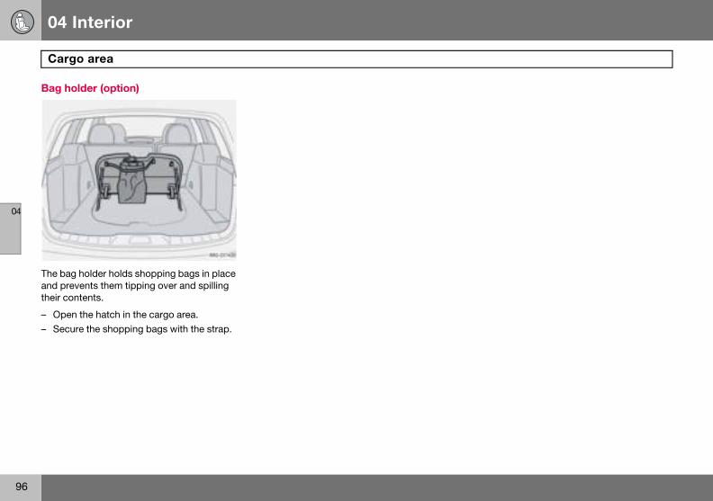
04 Interior
96
Carg
04
Bag ho
The bagand pretheir con
– Open– Secu
o area
lder (option)
holder holds shopping bags in place vents them tipping over and spilling tents.
the hatch in the cargo area.re the shopping bags with the strap.
04 Interior
97
04
98
Remote control with key blade .............................................................. 100Keyless drive (option) ............................................................................. 104Locking and unlocking ........................................................................... 107Child safety locks ................................................................................... 110Alarm (option).......................................................................................... 111
05LOCKS AND ALARM
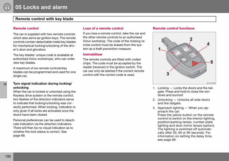
05 Locks and alarm
100
Rem
05
Remot
The car which acontrolsfor mecer’s doo
The keyauthorisnew key
A maximblades csingle c
Turn sigunlockiWhen thKeylesstwo flasto indicarectly peonly givdoors h
Personavate indThere wwhetherpage 68
Remote control functions
1. Locking — Locks the doors and the tail-gate. Press and hold to close the win-dows and sunroof.
2. Unlocking — Unlocks all side doors and the tailgate.
3. Approach lighting — When you ap-proach the car: Press the yellow button on the remote control to switch on the interior lighting, position/parking lamps, number plate lighting and door mirror lamps (option). The lighting is switched off automati-cally after 30, 60 or 90 seconds. For information on setting the delay time, see page 69.
ote control with key blade
e control
is supplied with two remote controls lso serve as ignition keys. The remote contain detachable metal key blades hanical locking/unlocking of the driv-r and glovebox.
blades’ unique code is available at ed Volvo workshops, who can order blades.
um of six remote controls/key an be programmed and used for one
ar.
nal indication during locking/nge car is locked or unlocked using the drive system or the remote control, hes of the direction indicators serve te that locking/unlocking was cor-rformed. When locking, indication is
en if all locks are activated once the ave been closed.
l preferences can be used to deacti-ication via the direction indicators. ill then be no visual indication as to the lock status is correct. See .
Loss of a remote controlIf you lose a remote control, take the car and the other remote controls to an authorised Volvo workshop. The code of the missing re-mote control must be erased from the sys-tem as a theft prevention measure.
Immobiliser The remote controls are fitted with coded chips. The code must be accepted by the reader (receiver) in the ignition switch. The car can only be started if the correct remote control with the correct code is used.

05 Locks and alarm
101
Remote control with key blade
05
4. Tailgunlo
5. Pantion the rondssecocatobe tuonce5 seswit30 s
Key blaThis feacar, suchotel. Hthe rem
NO
The fun
IM
The naparticuchip. Tdamag
ate — Press the button once to ck the tailgate only.
ic function — Used to attract atten-in an emergency. Press and hold ed button for at least three sec- or press it twice within three nds to activate the direction indi-rs and the horn. The function can rned off with the same button it has been active for at least
conds. Otherwise the function ches off automatically after econds.
de ture is intended for when leaving the h as for servicing or valet parking at a and over the remote control and keep ovable key blade.
Removing the key bladeTo take the key blade out of the remote con-trol:
– Slide the spring-loaded catch (1) to the side while pulling the key blade (2) out.
Inserting the key bladeBe careful when inserting the key blade into the remote control.
– Hold the remote control with the narrow end pointing down and lower the key blade into its slot.
– Lightly press the key blade to lock it in position. You should hear a "click".
TE
ction does not open the tailgate.
PORTANT
rrow section of the remote control is larly sensitive - this contains the he car cannot be started if the chip is ed.
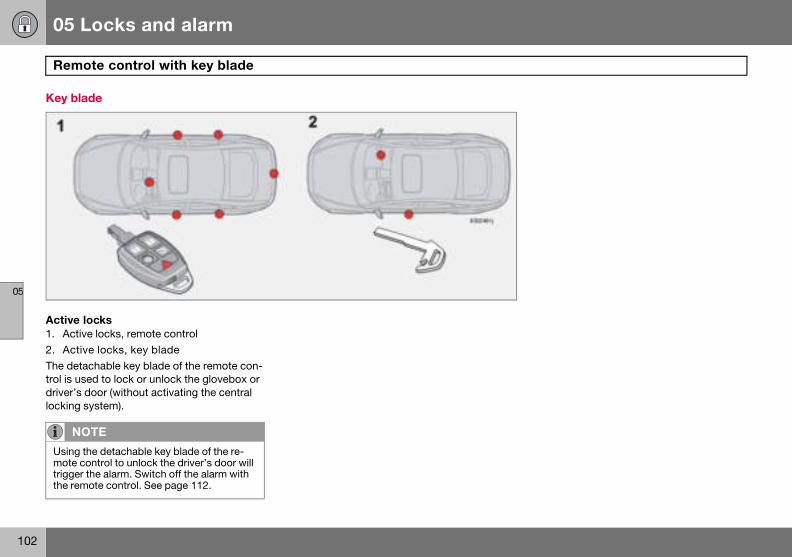
05 Locks and alarm
102
Rem
05
Key bla
Active 1. Activ2. ActiThe detatrol is usdriver’s locking
NO
Using mote ctriggerthe rem
ote control with key blade
de
lockse locks, remote control
ve locks, key bladechable key blade of the remote con-ed to lock or unlock the glovebox or door (without activating the central system).
TE
the detachable key blade of the re-ontrol to unlock the driver’s door will the alarm. Switch off the alarm with ote control. See page 112.
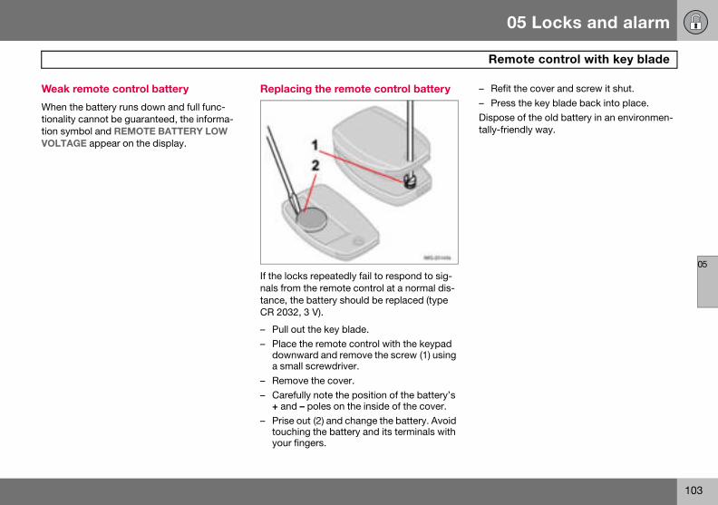
05 Locks and alarm
103
Remote control with key blade
05
Weak r
When thtionalitytion symVOLTAG
– Refit the cover and screw it shut.– Press the key blade back into place.Dispose of the old battery in an environmen-tally-friendly way.
emote control battery
e battery runs down and full func- cannot be guaranteed, the informa-bol and REMOTE BATTERY LOW E appear on the display.
Replacing the remote control battery
If the locks repeatedly fail to respond to sig-nals from the remote control at a normal dis-tance, the battery should be replaced (type CR 2032, 3 V).
– Pull out the key blade.– Place the remote control with the keypad
downward and remove the screw (1) using a small screwdriver.
– Remove the cover.– Carefully note the position of the battery’s
+ and – poles on the inside of the cover.– Prise out (2) and change the battery. Avoid
touching the battery and its terminals with your fingers.
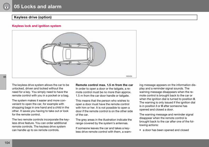
05 Locks and alarm
104
Keyle
05
Keyles
The keyunlockeneed forremote
The sysvenient shoppinother. Itfor the r
The twoless drivremote can han
ing message appears on the information dis-play and a reminder signal sounds. The warning message disappears when the re-mote control is brought back to the car or when the ignition dial is turned to position 0. The warning is only issued if the ignition dial is in position I or II after someone has opened and closed a door.
The warning message and reminder signal disappear when the remote control is brought back to the car after one of the fol-lowing actions:
• a door has been opened and closed
ss drive (option)
s lock and ignition system
less drive system allows the car to be d, driven and locked without the a key. You simply need to have the
control with you in a pocket or a bag.
tem makes it easier and more con-to open the car, for example with g bags in one hand and a child in the saves you having to take out or look emote control.
remote controls incorporate the key-e feature. You can order additional controls. The keyless drive system dle up to six remote controls.
Remote control max. 1.5 m from the carIn order to open a door or the tailgate, a re-mote control must be no more than approx. 1.5 m from the car door handle or tailgate.
This means that the person who wishes to open a door must have the remote control with him or her. It is not possible to open a door if the remote control is on the other side of the car.
The grey areas in the illustration indicate the range covered by the system’s antennas.
If someone leaves the car and takes a key-less drive remote control with them, a warn-
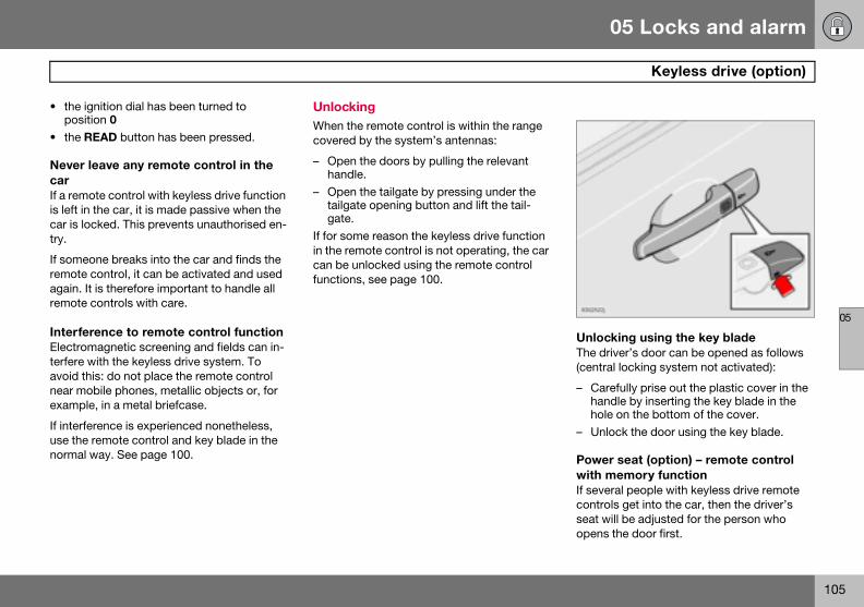
05 Locks and alarm
105
Keyless drive (option)
05
• the igposit
• the R
Never lcarIf a remois left in car is lotry.
If someoremote again. Itremote
InterferElectromterfere wavoid thnear moexample
If interfeuse the normal w
Unlocking using the key bladeThe driver’s door can be opened as follows (central locking system not activated):
– Carefully prise out the plastic cover in the handle by inserting the key blade in the hole on the bottom of the cover.
– Unlock the door using the key blade.
Power seat (option) – remote control with memory functionIf several people with keyless drive remote controls get into the car, then the driver’s seat will be adjusted for the person who opens the door first.
nition dial has been turned to ion 0EAD button has been pressed.
eave any remote control in the
te control with keyless drive function the car, it is made passive when the cked. This prevents unauthorised en-
ne breaks into the car and finds the control, it can be activated and used is therefore important to handle all controls with care.
ence to remote control functionagnetic screening and fields can in-ith the keyless drive system. To
is: do not place the remote control bile phones, metallic objects or, for , in a metal briefcase.
rence is experienced nonetheless, remote control and key blade in the
ay. See page 100.
UnlockingWhen the remote control is within the range covered by the system’s antennas:
– Open the doors by pulling the relevant handle.
– Open the tailgate by pressing under the tailgate opening button and lift the tail-gate.
If for some reason the keyless drive function in the remote control is not operating, the car can be unlocked using the remote control functions, see page 100.

05 Locks and alarm
106
Keyle
05
LockinLock the
– Pushhand
All doorfore thethey will
When ththe insid
PersonThe Keypreferen
ss drive (option)
g doors and tailgate as follows:
in the lock button on one of the door les.s and the tailgate must be closed be- lock button is pushed in. Otherwise not lock.
e car is locked, the lock buttons on e of the doors retract.
al preferencesless Drive system can have personal ces applied, see page 69.
05 Locks and alarm
107
Locking and unlocking
05
Lockinoutside
UnlockThe remthe car ipersona
• with otailga
• with oand wdoor
LockingThe remand the lock butgaged.
The fuelis locked
Tailgate
UnlockingUnlocking tailgate only:
– Press the remote control button to unlock the tailgate.
LockingIf the doors are locked when the tailgate is closed then it remains unlocked. Lock with the remote control or from inside to lock the both doors and the tailgate.
NO
The catailgatethere is
1Applie
g/unlocking the car from
ingote control unlock button can unlock n two different ways (select option in l preferences, see page 69):
ne press unlock both doors and the tene press unlock the driver’s door ith a second press unlock the other
and the tailgate.
ote control locks both side doors tailgate simultaneously. The door tons and inside handles are disen-
filler flap cannot be opened if the car with the remote control.
Automatic relocking If none of the doors or the tailgate is opened within two minutes of unlocking, all are locked again automatically (does not apply to locking from inside). This function prevents the car from being left unlocked unintention-ally. For cars with alarms, see page 112.
Automatic locking When the speed of the car exceeds 7 km/h the doors and tailgate can be locked auto-matically.
When the function is activated and the doors have been locked they can be opened in two ways:
• pull one of the door handles twice• press the unlock button by the door han-
dle.The function can be activated/deactivated by means of personal preferences, see page 69.
TE
r can be locked1 even if a door or the is open. When the door is closed a risk that the keys will be locked in.
s to certain markets
WARNING
Be aware that you can be locked in the car if it is locked from the outside with the remote control. You cannot leave the car using any of the controls inside the car.
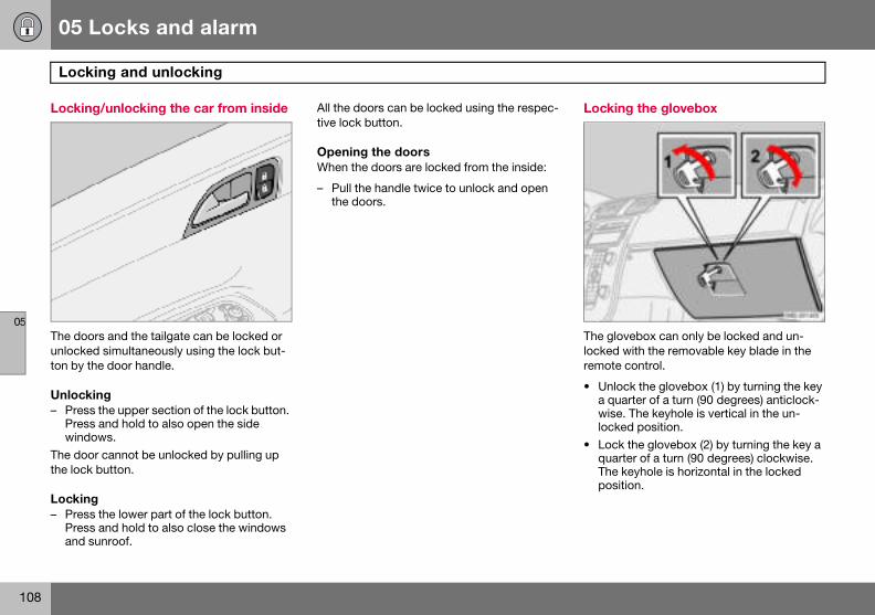
05 Locks and alarm
108
Lock
05
Lockin
The doounlocketon by th
Unlock– Press
Presswindo
The doothe lock
Locking– Press
Pressand s
Locking the glovebox
The glovebox can only be locked and un-locked with the removable key blade in the remote control.
• Unlock the glovebox (1) by turning the key a quarter of a turn (90 degrees) anticlock-wise. The keyhole is vertical in the un-locked position.
• Lock the glovebox (2) by turning the key a quarter of a turn (90 degrees) clockwise. The keyhole is horizontal in the locked position.
ing and unlocking
g/unlocking the car from inside
rs and the tailgate can be locked or d simultaneously using the lock but-e door handle.
ing the upper section of the lock button. and hold to also open the side ws.r cannot be unlocked by pulling up button.
the lower part of the lock button. and hold to also close the windows unroof.
All the doors can be locked using the respec-tive lock button.
Opening the doorsWhen the doors are locked from the inside:
– Pull the handle twice to unlock and open the doors.

05 Locks and alarm
109
Locking and unlocking
05
Deadlo
When dopenedThe deacontrol.25 seco
The car lock stacan alsokey.
The light in the button illuminates until the car is locked with the key or the remote control. A message remains on the display as long as the key is in the ignition switch. The detec-tors are reactivated and deadlocks re-en-gaged the next time the ignition is switched on.
WARNING
Do not allow anyone to remain in the car without first deactivating the deadlocks.
cks
eadlocked, the doors cannot be from the inside if they are locked. dlocks are activated with the remote The deadlocks are set after a nd delay after the doors are locked.
can only be unlocked from a dead-te with the remote control. The doors be opened from the outside with the
Temporary deactivation of the deadlocks and any detectors
1. Deactivation of the detectors and dead-locks
2. No functionIf someone is going to stay in the car but you still want to lock the doors from the outside, the deadlocks can be disabled.
– Insert the key into the ignition switch, turn it to position II and then back to position I or 0.
– Press button (1).If the car is equipped with an alarm, move-ment and tilt detectors are also deactivated. See page 112.
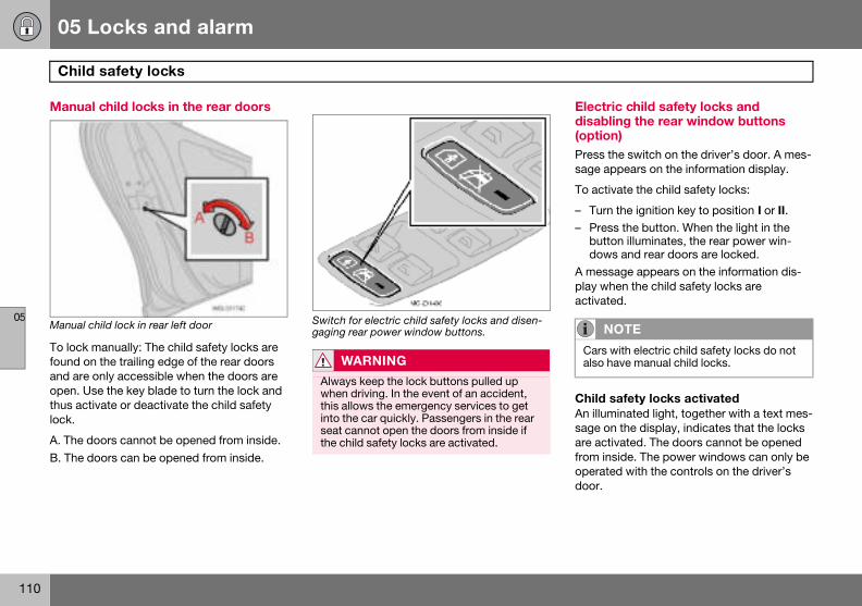
05 Locks and alarm
110
Child
05
Manua
Manual c
To lock found oand are open. Uthus actlock.
A. The dB. The d
Electric child safety locks and disabling the rear window buttons (option)Press the switch on the driver’s door. A mes-sage appears on the information display.
To activate the child safety locks:
– Turn the ignition key to position I or II.– Press the button. When the light in the
button illuminates, the rear power win-dows and rear doors are locked.
A message appears on the information dis-play when the child safety locks are activated.
Child safety locks activatedAn illuminated light, together with a text mes-sage on the display, indicates that the locks are activated. The doors cannot be opened from inside. The power windows can only be operated with the controls on the driver’s door.
NOTE
Cars with electric child safety locks do not also have manual child locks.
safety locks
l child locks in the rear doors
hild lock in rear left door
manually: The child safety locks are n the trailing edge of the rear doors only accessible when the doors are se the key blade to turn the lock and ivate or deactivate the child safety
oors cannot be opened from inside.oors can be opened from inside.
Switch for electric child safety locks and disen-gaging rear power window buttons.
WARNING
Always keep the lock buttons pulled up when driving. In the event of an accident, this allows the emergency services to get into the car quickly. Passengers in the rear seat cannot open the doors from inside if the child safety locks are activated.
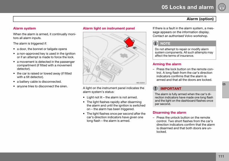
05 Locks and alarm
111
Alarm (option)
05
Alarm
When thtors all a
The alar
• a doo• a non
or if a• a mo
compdetec
• the cwith a
• a bat• anyo
If there is a fault in the alarm system, a mes-sage appears on the information display. Contact an authorised Volvo workshop.
Arming the alarm – Press the lock button on the remote con-
trol. A long flash from the car’s direction indicators confirms that the alarm is armed and that all the doors are locked.
Disarming the alarm – Press the unlock button on the remote
control. Two short flashes from the car’s direction indicators confirm that the alarm is disarmed and that both doors are un-locked.
NOTE
Do not attempt to repair or modify alarm system components. All such attempts may affect the terms of insurance.
IMPORTANT
The alarm is fully armed when the car’s di-rection indicators have made one long flash and the light on the dashboard flashes once per second.
system
e alarm is armed, it continually moni-larm inputs.
m is triggered if:
r, the bonnet or tailgate opens-approved key is used in the ignition n attempt is made to force the lock.vement is detected in the passenger artment (if fitted with a movement tor).
ar is raised or towed away (if fitted tilt detector).
tery cable is disconnected.ne tries to disconnect the siren.
Alarm light on instrument panel
A light on the instrument panel indicates the alarm system’s status:
• Light not lit – the alarm is not armed.• The light flashes rapidly after disarming
the alarm and until the ignition is switched on – the alarm has been triggered.
• The light flashes once per second after the car’s direction indicators have given one long flash – the alarm is armed.
05 Locks and alarm
112
Alarm
05
AutomThis funing the c
If none oopenedalarm (athe remly rearmtime.
Deacti– Press
contrswitc
Confirmfrom the
Alarm When thhappen
• A sire25 sewhichcient
• The dutes o
RemotIf for somworkingand the
– Turn the ignition key to position II and then back to position 0. Remove the key.
– Press button (1). The light in the button is illuminated until the car is locked.
A message remains on the display as long as the key remains in the ignition switch (and for one minute after the key is removed).
The detectors are reactivated the next time the ignition is switched on.
If the car has deadlocks, these are also re-engaged.
(option)
atic alarm activation ction prevents you accidentally leav-ar without the alarm on.
f the doors or the tailgate are within two minutes of disarming the nd the car has been unlocked with ote control), the alarm is automatical-ed, and the car is locked at the same
vating a triggered alarm the unlock button on the remote ol or insert the key in the ignition h.ation is given by two short flashes direction indicators.
signals e alarm is triggered, the following
s:
n sounds for no more than conds. The siren has its own battery is used if the car battery has insuffi-
charge or is disconnected.irection indicators flash for five min-r until the alarm is deactivated.
e control not workinge reason the remote control is not
, the alarm can still be switched off car started as follows:
– Open the driver’s door with the key blade. The alarm is triggered and the siren sounds.
– Insert the remote control into the ignition switch. The alarm is deactivated. The alarm light flashes rapidly until the ignition key is turned to position II.
Temporary deactivation of the deadlocks and detectors
1. Deactivation of the detectors2. No functionTo prevent the alarm being tripped errone-ously, such as during a ferry journey, the movement and tilt detectors can be tempo-rarily disengaged.
05 Locks and alarm
113
Alarm (option)
05
Testing
Testingpassen– Open– Arm t
firme– Wait – Test
sengout asounflash.
– Deacwith t
Testing– Arm t– Wait – Unloc
blade– Open
soun– Deac
with t
Testing– Sit in
ment
the alarm system
the movement detector in the ger compartment all the windows.he alarm. Arming the alarm is con-d by the light flashing slowly.30 seconds.the movement detector in the pas-er compartment, such as by lifting bag from a seat. A siren should d and all direction indicators should
tivate the alarm by unlocking the car he remote control.
the doorshe alarm.30 seconds.k the driver’s door with the key . one of the doors. A siren should d and all direction indicators flash.tivate the alarm by unlocking the car he remote control.
the bonnet the car and deactivate the move- detector.
– Arm the alarm. Remain in the car and lock the doors with the button on the remote control.
– Wait 30 seconds.– Open the bonnet with the handle under
the dashboard. A siren should sound and all direction indicators flash.
– Deactivate the alarm by unlocking the car with the remote control.
114
General.................................................................................................... 116Refuelling ............................................................................................... 118Starting the engine................................................................................. 119Keyless drive (option) ............................................................................. 121Manual gearbox ..................................................................................... 122Automatic gearbox................................................................................. 124All-wheel drive........................................................................................ 127Brake system .......................................................................................... 128Stability and traction control system........................................................................................ 130Parking assistance (option) .................................................................... 132Blind Spot Information System (BLIS, option) ....................................... 134Towing and recovery .............................................................................. 137Start assistance ..................................................................................... 139Driving with a trailer ............................................................................... 140Towing equipment .................................................................................. 142Detachable towbar ................................................................................. 144Loading .................................................................................................. 149Adjusting headlamp pattern................................................................... 150
06STARTING AND DRIVING
06 Starting and driving
116
Gene
06
Econom
Driving ewhile thing styletions.
• Get tposs
• Do noloads
• A colwarm
• Avoid• Do no
car.• Do no
are d• Remo
being• Avoid
SlipperPractisecontrolleacts.
EngineUnder sdriving iheavy loand coo
Driving in water The car can be driven through water at a maximum depth of 25 cm at a maximum speed of 10 km/h. Extra caution should be exercised when passing through flowing wa-ter.
When driving in water, maintain a low speed and do not stop the car. When the water has been passed, depress the brake pedal lightly and check that full brake function is attained. Water and mud for example can make the brake linings wet resulting in delayed brake function.
IMPORTANT
Engine damage can occur if water enters the air filter. In greater depths, water can enter the trans-mission. This reduces the lubricating ability of the oils and shortens the service life of these systems.
ral
ical driving
conomically means driving smoothly inking ahead and adjusting your driv- and speed to the prevailing condi-
he engine warmed up as soon as ible. t let the engine idle, but drive at light as soon as it is possible. d engine consumes more fuel than a one. braking too hard.t drive with unnecessary loads in the
t use winter tyres when the roads ry.ve load carriers when they are not used. driving with open windows.
y driving conditions driving on slippery surfaces under d conditions to learn how the car re-
and cooling system pecial conditions, for example when n hilly terrain, extreme heat or with ads, there is a risk that the engine ling system will overheat.
Avoid overheating the cooling system• Maintain a low speed when driving with a
trailer up long, steep ascents.• Do not turn the engine off immediately you
stop after a hard drive.• Remove any auxiliary lamps from in front
of the grille if driving in extreme high temperatures.
Avoid overheating the engineDo not exceed engine speeds of 4500 rpm (diesel engine: 3500 rpm) if driving with a trailer or caravan in hilly terrain. The oil tem-perature could then become too high.
Open tailgate Avoid driving with the tailgate open. If it is necessary to drive with the tailgate open for a short distance:
– Close all windows.– Set the air distribution to the windscreen
and floor and run the fan at high speed.
WARNING
Do not drive with the tailgate open. Toxic exhaust fumes can be drawn into the car through the cargo area.
06 Starting and driving
117
General
06
Clean thgine blodriving i
IM
Do notsills forcause In the erestart
e electric contacts of the electric en-ck heater and trailer coupling after n water and mud.
Do not overload the battery The electrical functions in the car load the battery to varying degrees. Avoid using the ignition position II when the engine is switched off. Use ignition position I instead, as less power is consumed.
Examples of functions that use a lot of pow-er:
• ventilation fan• windscreen wipers• audio equipment (high volume)• parking lightsAlso, be aware of different accessories that load the electrical system. Do not use func-tions which use a lot of power when the en-gine is switched off.
If the battery voltage is low, a message ap-pears on the display. The energy-saving function shuts down certain functions or re-duces the load on the battery by, for exam-ple, slowing the ventilation fan and switching off the audio equipment. Charge the battery by starting the engine.
PORTANT
let the car stand with water over the any long period of time. This could electrical malfunctions. vent of stalling in water, do not try to
. Tow the car out of the water.
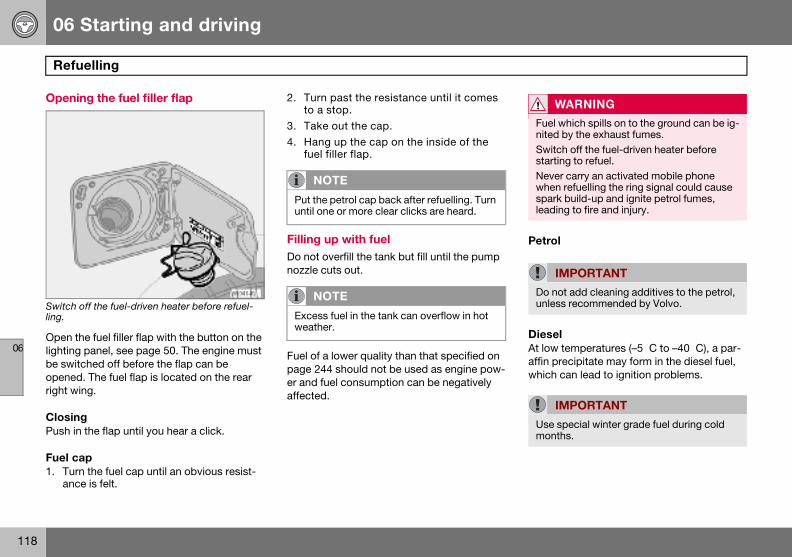
06 Starting and driving
118
Refu
06
Openin
Switch oling.
Open thlighting be switcopenedright win
ClosingPush in
Fuel ca1. Turn
ance
Petrol
DieselAt low temperatures (–5 �C to –40 �C), a par-affin precipitate may form in the diesel fuel, which can lead to ignition problems.
WARNING
Fuel which spills on to the ground can be ig-nited by the exhaust fumes.Switch off the fuel-driven heater before starting to refuel.Never carry an activated mobile phone when refuelling the ring signal could cause spark build-up and ignite petrol fumes, leading to fire and injury.
IMPORTANT
Do not add cleaning additives to the petrol, unless recommended by Volvo.
IMPORTANT
Use special winter grade fuel during cold months.
elling
g the fuel filler flap
ff the fuel-driven heater before refuel-
e fuel filler flap with the button on the panel, see page 50. The engine must hed off before the flap can be
. The fuel flap is located on the rear g.
the flap until you hear a click.
p the fuel cap until an obvious resist- is felt.
2. Turn past the resistance until it comes to a stop.
3. Take out the cap. 4. Hang up the cap on the inside of the
fuel filler flap.
Filling up with fuel Do not overfill the tank but fill until the pump nozzle cuts out.
Fuel of a lower quality than that specified on page 244 should not be used as engine pow-er and fuel consumption can be negatively affected.
NOTE
Put the petrol cap back after refuelling. Turn until one or more clear clicks are heard.
NOTE
Excess fuel in the tank can overflow in hot weather.
06 Starting and driving
119
Starting the engine
06
Before– Apply
Automa– Gear
ManuaPut the clutch plarly imp
Diesel particle filter (DPF)1 Diesel cars may be equipped with a particle filter, which results in more efficient emission control. The particles in the exhaust gases are collected in the filter during normal driv-ing. So-called "regeneration" is started in or-der to burn away the particles and empty the filter. This requires the engine to have reached normal operating temperature.
Regeneration of the filter takes place auto-matically at an interval of 300 – 900 km de-pending on driving conditions. Regeneration normally takes between 10 and 20 minutes. During this time fuel consumption may in-crease slightly.
The rear window heating may be activated automatically to increase the load on the en-gine during regeneration without warning.
Regeneration in cold weather If the car is frequently driven short distances in cold weather then the engine does not reach normal operating temperature. This means that regeneration of the diesel particle filter does not take place and the filter is not emptied.
When the filter has become approximately 80% full of particles, the yellow information
W
Never steerinbeing twise bsteer thThe ignthe car
NO
The idlthan nocold stsystemature aes exhenviron
1 Certain markets.
starting the engine the parking brake.
tic gearbox selector in position P or N.
l gearboxgear lever in neutral and hold the edal fully depressed. This is particu-ortant in very cold conditions.
Starting the engine
Petrol– Turn the ignition key to position III.
If the engine does not start within 5–10 seconds, release the key and try again.
Diesel1. Turn the ignition key to position II.
An indicator symbol in the combined in-strument panel shows that engine pre-heating is underway, see page 43.
2. Turn the ignition key to position III when the indicator symbol goes out.
Autostart (5-cylinder) With the autostart function, there is no need to hold the ignition key (or ignition dial on cars with Keyless Drive, see page 104) in position III until the engine has started.
Turn the ignition key to the start position and then release. The starter motor then works automatically until the engine has started.
ARNING
remove the ignition key from the g lock while driving or when the car is owed. The steering lock could other-e activated, making it impossible to e car.ition key must be in position II when is being towed.
TE
ing speed can be noticeably higher rmal for certain engine types during
arting. This is so that the emissions can reach normal operating temper-s quickly as possible, which minimis-aust emissions and protects the ment.
NOTE
If the diesel engine is started in extreme cold without waiting for engine preheating, then the automatic start sequence can be delayed for a couple of seconds.

06 Starting and driving
120
Start
06
symbol the mesUAL is s
Start regcar untiltemperamotorwapproxi
When reis cleare
Use theweatheroperatin
IgnitionimmobThe ignikeys or Otherwibe activ
When the steering lock is activatedIf the front wheels are positioned so that there is tension in the steering lock, a warn-ing message may be shown in the informa-tion display and the car prohibited from start-ing.
1. Remove the key and turn the steering wheel to release the tension.
2. Hold the steering wheel in this position. Reinsert the key and make a new at-tempt to start the car.
Make sure the steering lock is activated when the car is left to reduce the risk of theft.
IM
If the fifunctiothe engwill hav
WARNING
Never remove the ignition key from the igni-tion switch while driving or when the car is being towed. The steering lock could other-wise be activated, making it impossible to steer the car.
WARNING
Always remove the ignition key from the ig-nition when leaving the car, especially if there are children in the car.
ing the engine
on the dashboard illuminates, and sage SOOT FILTER FULL SEE MAN-hown on the dashboard display.
eneration of the filter by driving the the engine reaches normal operating ture, preferably on a main road or
ay. The car should then be driven for mately 20 minutes more.
generation is complete the message d automatically.
parking heater (option) in cold so that the engine reaches normal g temperature more quickly.
keys and electronic iliser tion key must not hang with other metal objects on the same key ring. se the electronic immobiliser could ated accidentally.
Ignition switch and steering lock
0 – Locked positionThe steering lock is activat-ed when the key is removed from the lock.
I – Radio positionCertain electrical compo-nents can be switched on. The engine’s electrical sys-tem is not activated.
II – Driving positionThe key position when driv-ing. The car’s electrical sys-tem is energised.
III – Start positionThe starter motor is en-gaged. Release the key, which springs back auto-matically to the driving po-sition, once the engine has started.
A ticking sound may be heard if the key is be-tween positions. Turn the key to position II and back to eliminate the sound.
PORTANT
lter fills up it may be incapable of ning. Then it can be difficult to start ine and there is a risk that the filter e to be replaced.
06 Starting and driving
121
Keyless drive (option)
06
Genera
The keybe unlocneed for
The ignisame wstarting trol is loment or
Starting with the remote control
If the remote control battery is discharged then the Keyless Drive function does not work. In which case, start the car by using the remote control as ignition dial.
1. Press in the catch in the ignition dial and then pull it out from the ignition switch.
2. Insert the remote control into the igni-tion switch and start in the same way as with the ignition dial.
l
less drive function allows the car to ked, driven and locked without the a key, see page 104.
tion switch ignition dial is used in the ay as the key. One precondition for the car is that the car’s remote con-cated inside the passenger compart- the cargo area.
Starting the car – Depress the clutch pedal (cars with manu-
al gearbox) or brake pedal (cars with auto-matic gearbox).
Petrol engine– Press in and turn the ignition dial to
position III.
Diesel engine1. First turn the ignition dial to position II
and wait until the diesel indicator symbol in the combined instrument panel goes out, see page 43.
2. Following which, turn the ignition dial to position III.

06 Starting and driving
122
Manu
06
Gear p
Depresschange.pedal bepropriat
For the highest
Gear positions, six-speed (petrol)
Depress the clutch pedal fully with each gear change. Remove your foot from the clutch pedal between gear changes! Follow the ap-propriate shifting pattern.
For the best possible fuel economy, use the highest gear possible as often as possible.
It can be difficult to find the positions for fifth and sixth gear when the car is stationary as the reverse gear inhibitor (which blocks side-ways movement towards reverse) is then not activated.
al gearbox
ositions, five-speed
the clutch pedal fully with each gear Remove your foot from the clutch tween gear changes! Follow the ap-
e shifting pattern.
best possible fuel economy, use the gear possible as often as possible.
Reverse gear inhibitor, five-speed
Only engage reverse gear when the car is stationary. To engage reverse gear, the gear lever must first be put in position N. Reverse gear cannot therefore be engaged directly from fifth gear due to the reverse gear inhibi-tor.
06 Starting and driving
123
Manual gearbox
06
Revers(petrol)
Only enstationa
Reverse gear inhibitor, six-speed (diesel)
Only engage reverse gear when the car is stationary. Engage reverse gear by pressing down the gear lever and moving it to the left.
NO
Reverscar is t
e gear inhibitor, six-speed
gage reverse gear when the car is ry.
Gear positions, six-speed (diesel)1
Depress the clutch pedal completely for each gear change. Remove your foot from the clutch pedal between gear changes. Follow the indicated gear pattern. For optimum fuel economy use the highest possible gear as of-ten as possible.
TE
e gear is electronically blocked if the ravelling faster than approx. 20 km/h.
1 Certain markets.
06 Starting and driving
124
Auto
06
Cold st
When stchangesdue to tperaturegearboxengine i
Kick-dWhen thway to tly regardis immekick-dow
If the acdown pochanges
Kick-dotion is n
To preveprogramwhich p
The kickmanual
Disengaging shiftlock
In certain cases, it may be necessary to move the car when it is not driveable, for ex-ample if the battery is flat. Proceed as follows to move the car:
1. There is a small cover behind P-R-N-D on the gear selector panel. Open the rear edge.
2. Fully insert the key blade from the remote control.
3. Hold the key blade down and at the same time move the gear selector out of the P position.
NO
Depenthe engcold stcertain
matic gearbox
art
arting in low temperatures, the gear can sometimes feel hard. This is
he gearbox oil’s viscosity at low tem-s. To minimise engine emissions, the shifts up later than normal when the s started at low temperatures.
own e accelerator pedal is pressed all the he floor, beyond the position normal-ed as full acceleration, a lower gear
diately engaged. This is known as n.
celerator is released from the kick-sition, the gearbox automatically up.
wn is used when maximum accelera-eeded, such as for overtaking.
nt overrevving, the gearbox control has a protective downshift inhibitor
revents the kick-down function.
-down function cannot be used in gear position (Geartronic).
Safety systems Cars with an automatic gearbox have special safety systems:
KeylockTo remove the ignition key, the gear selector must be in the P position. The key is locked in all other positions.
Parking position (P)Stationary car with engine running:
– Hold your foot on the brake pedal when moving the gear selector to another posi-tion.
Electric gear inhibitor – Shiftlock Parking position (P position)To be able to move the gear selector from the P position to other gear positions, the ignition key must be in position II and the brake ped-al must be depressed.
Shiftlock – Neutral (N position)If the gear selector is in the N position and the car has been stationary for at least three seconds (irrespective of whether the engine is running) then the gear selector is locked in the N position.
To be able to move the gear selector from the N position to another gear position, the brake pedal must be depressed and the ignition key must be in position II.
TE
ding on the engine temperature when ine is started, the idle speed after a
art may be higher than normal for engine types.
06 Starting and driving
125
Automatic gearbox
06
Mecha
The geabetweenwith a labutton o
Press thforwardposition
The gearbox is mechanically blocked when P position is engaged. Always apply the park-ing brake when parking the car.
R – ReverseThe car must be stationary when R is select-ed.
N – NeutralN is the neutral position. No gear is engaged and the engine can be started. Apply the parking brake when the car is stationary with the gear selector in position N.
D – DriveD is the normal driving position. Shifting up and down between the different gearbox ra-tios occurs automatically based on the level of acceleration and speed. The car should be stationary when the gear lever is moved from position R to position D.
nical gear selector inhibitor
r selector can be moved freely N and D. Other positions are locked tch that is released with the inhibitor n the gear selector.
e inhibitor button to move the lever or back between the different gear s.
Automatic gear positions
P – Parking positionSelect position P when you wish to start the engine or park the car.
IMPORTANT
The car must be stationary when position P is selected.
NOTE
The brake pedal must be depressed to move the gear selector from the P position.
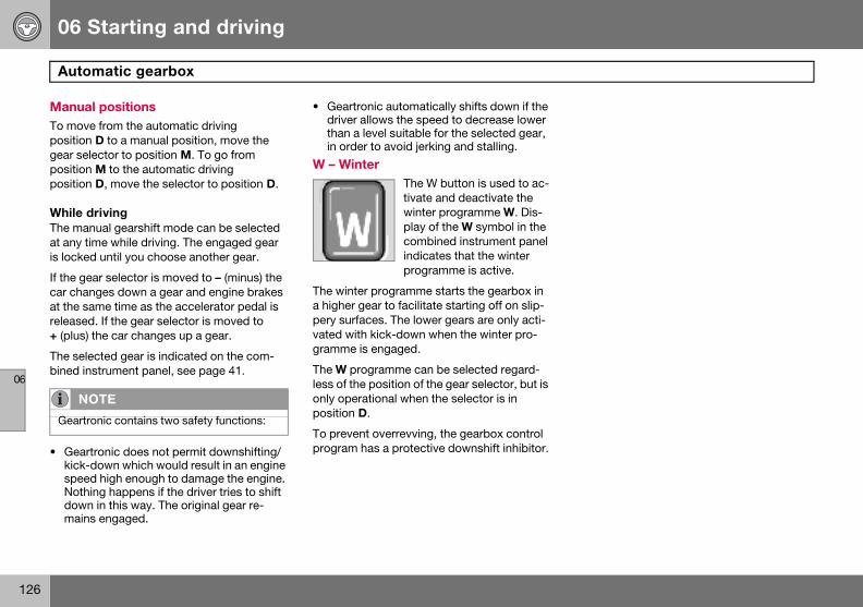
06 Starting and driving
126
Auto
06
ManuaTo movepositiongear selpositionposition
While dThe manat any tiis locked
If the gecar chanat the sareleased+ (plus)
The selebined in
• Gearkick-speeNothdownmain
NO
Geartr
matic gearbox
l positions from the automatic driving
D to a manual position, move the ector to position M. To go from M to the automatic driving D, move the selector to position D.
rivingual gearshift mode can be selected
me while driving. The engaged gear until you choose another gear.
ar selector is moved to – (minus) the ges down a gear and engine brakes me time as the accelerator pedal is . If the gear selector is moved to
the car changes up a gear.
cted gear is indicated on the com-strument panel, see page 41.
tronic does not permit downshifting/down which would result in an engine d high enough to damage the engine. ing happens if the driver tries to shift in this way. The original gear re-
s engaged.
• Geartronic automatically shifts down if the driver allows the speed to decrease lower than a level suitable for the selected gear, in order to avoid jerking and stalling.
W – Winter The W button is used to ac-tivate and deactivate the winter programme W. Dis-play of the W symbol in the combined instrument panel indicates that the winter programme is active.
The winter programme starts the gearbox in a higher gear to facilitate starting off on slip-pery surfaces. The lower gears are only acti-vated with kick-down when the winter pro-gramme is engaged.
The W programme can be selected regard-less of the position of the gear selector, but is only operational when the selector is in position D.
To prevent overrevving, the gearbox control program has a protective downshift inhibitor.
TE
onic contains two safety functions:
06 Starting and driving
127
All-wheel drive
06
All-whe
All-whee
All-wheewheels aautomatrear wheclutch spair of wthe best
Under nof powe
All-wheerain, sno
el drive – AWD
l drive is always engaged.
l drive means that all four road re driven at the same time. Power is ically distributed between front and els. An electronically controlled
ystem distributes the power to the heels that grips best. This provides traction and prevents wheel spin.
ormal driving conditions, the majority r is transmitted to the front wheels.
l drive improves driving safety in w and icy conditions.
06 Starting and driving
128
Brak
06
Brake s
If the caengine tpressedthe engipressedfeel the the brakbe morebrake as
Brake
the car. and maypressurethe norm
engine braking more efficiently and requires the foot brake for only brief periods.
Bear in mind that driving with a trailer puts an additional load on the car’s brakes.
Anti-lock braking system (ABS) The anti-lock braking system (ABS) prevents the wheels from locking up under braking. This means the ability to steer is
maintained and it is easier to swerve to avoid a hazard, for example.
After the engine has been started, the ABS will perform a brief self-test at a speed of about 20 km/h. This can be felt and heard as pulses in the brake pedal.
To get the most out of the ABS:
1. Depress brake pedal with full force. Puls-es will be felt.
2. Steer the car in the direction of travel. Do not release the pressure on the pedal.
Practice braking with the ABS system in a traffic-free area and in different weather con-ditions.
The ABS symbol illuminates for two seconds if there was a fault in the ABS system when the engine was last running.
W
The brgine is
NO
If brakipress tpeated
e system
ervo
r is rolling or is being towed with the urned off, the brake pedal must be about five times harder than when ne is running. If the brake pedal is when the engine is started, you will pedal drop. This is normal and due to e servo becoming active. This may noticeable if the car has emergency sistance (EBA).
circuitsThis symbol lights if a brake circuit is not working.
If a fault should occur in one of the circuits, it is still possible to brake
The brake pedal will travel further feel softer than normal. Harder on the pedal is needed to produce al braking effect.
Dampness can affect braking charac-teristicsBrake components become wet when the car is driven in heavy rain, through pools of water or when the car is washed. This may alter brake pad friction characteristics so that there is a delay before braking effect is no-ticed.
Press the brake pedal lightly from time to time if driving for long stretches in rain or slushy snow, as well as after setting off in very damp or cold weather. This warms up the braking surfaces and dries off any water. It is also recommended to do this before parking the car for a long period in such weather conditions.
If the brakes are used heavilyWhen driving in the Alps or other roads with similar characteristics, the car’s brakes are heavily loaded even if the brake pedal is not being depressed especially hard.
Because speed is often low, the brakes are not cooled as effectively as when driving on flat roads at higher speed.
So as not to overload the brakes, shift down when driving downhill instead of using the foot brake. Use the same gear driving down-hill as you would use driving uphill. This uses
ARNING
ake servo only works when the en- running.
TE
ng with the engine switched off, he brake pedal sharply once, not re-ly.
06 Starting and driving
129
Brake system
06
EmergIn case ing is prfunctionderway pedal iseasing osuspendpedal eaand can
W
If the Blit at thcurredbrake fly to thto haveIf the bthe brabeforeThe reabe inve
NO
When ers sligthe brabrake pceases
ency brake assistance – EBAof sudden braking, full-strength brak-ovided instantaneously. The EBA senses when heavy braking is un-by registering how quickly the brake depressed. Continue braking without ff on the brake pedal. The function is ed when the pressure on the brake ses. This function is always active not be disengaged.
ARNING
RAKE and ABS warning symbols are e same time, a fault may have oc- in the brake system. If the level in the luid reservoir is normal, drive careful-e nearest authorised Volvo workshop the brake system checked.rake fluid is under the MIN level in ke fluid reservoir, do not drive further topping up the brake fluid.son for the loss of brake fluid must stigated.
TE
EBA is activated the brake pedal low-htly more than usual, depress (hold) ke pedal as long as necessary. If the edal is released then all braking .
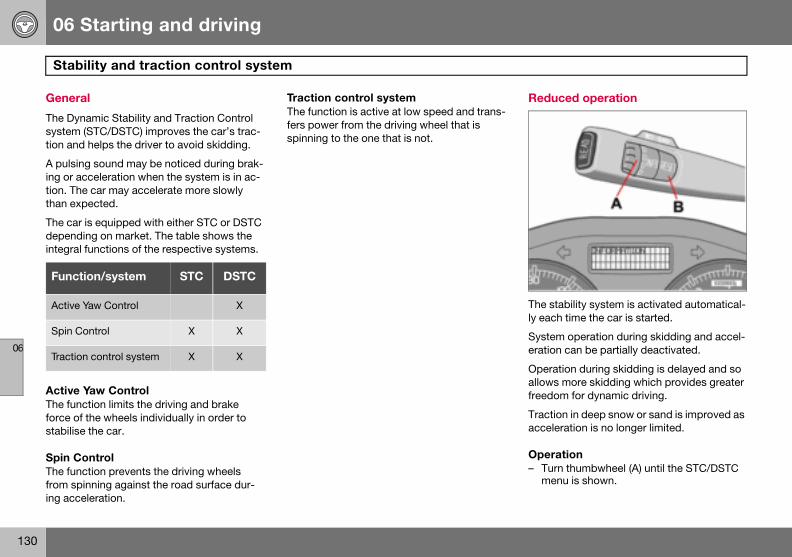
06 Starting and driving
130
Stab
06
Genera
The Dynsystem tion and
A pulsining or action. Thethan exp
The car dependintegral
Active The funcforce ofstabilise
Spin CoThe funcfrom sping acce
Reduced operation
The stability system is activated automatical-ly each time the car is started.
System operation during skidding and accel-eration can be partially deactivated.
Operation during skidding is delayed and so allows more skidding which provides greater freedom for dynamic driving.
Traction in deep snow or sand is improved as acceleration is no longer limited.
Operation – Turn thumbwheel (A) until the STC/DSTC
menu is shown.
Funct
Active
Spin C
Traction
ility and traction control system
l
amic Stability and Traction Control (STC/DSTC) improves the car’s trac- helps the driver to avoid skidding.
g sound may be noticed during brak-celeration when the system is in ac- car may accelerate more slowly ected.
is equipped with either STC or DSTC ing on market. The table shows the functions of the respective systems.
Yaw Controltion limits the driving and brake
the wheels individually in order to the car.
ntroltion prevents the driving wheels
inning against the road surface dur-leration.
Traction control systemThe function is active at low speed and trans-fers power from the driving wheel that is spinning to the one that is not.
ion/system STC DSTC
Yaw Control X
ontrol X X
control system X X
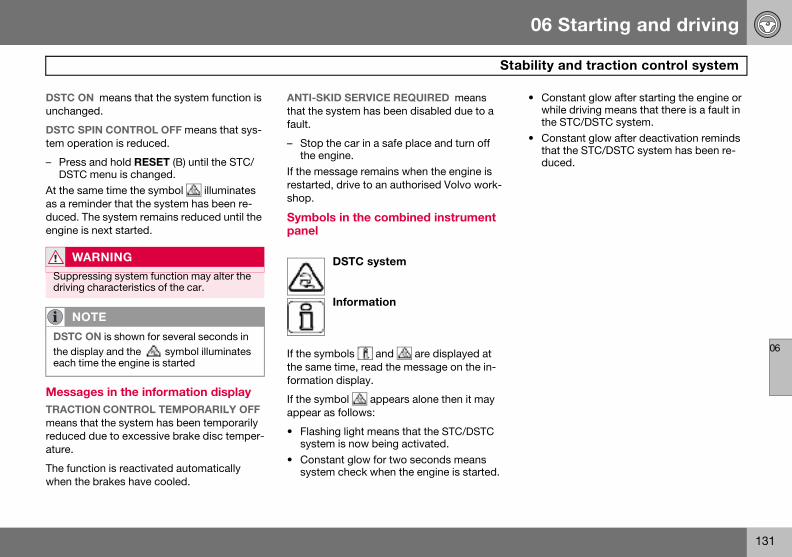
06 Starting and driving
131
bility and traction control system
06
DSTC Ounchang
DSTC Stem ope
– PressDSTC
At the saas a remduced. Tengine i
MessaTRACTImeans treducedature.
The funcwhen th
• Constant glow after starting the engine or while driving means that there is a fault in the STC/DSTC system.
• Constant glow after deactivation reminds that the STC/DSTC system has been re-duced.
W
Suppredriving
NO
DSTC the diseach ti
Sta
N means that the system function is ed.
PIN CONTROL OFF means that sys-ration is reduced.
and hold RESET (B) until the STC/ menu is changed.me time the symbol illuminates inder that the system has been re-he system remains reduced until the
s next started.
ges in the information displayON CONTROL TEMPORARILY OFF hat the system has been temporarily due to excessive brake disc temper-
tion is reactivated automatically e brakes have cooled.
ANTI-SKID SERVICE REQUIRED means that the system has been disabled due to a fault.
– Stop the car in a safe place and turn off the engine.
If the message remains when the engine is restarted, drive to an authorised Volvo work-shop.
Symbols in the combined instrument panel
DSTC system
Information
If the symbols and are displayed at the same time, read the message on the in-formation display.
If the symbol appears alone then it may appear as follows:
• Flashing light means that the STC/DSTC system is now being activated.
• Constant glow for two seconds means system check when the engine is started.
ARNING
ssing system function may alter the characteristics of the car.
TE
ON is shown for several seconds in play and the symbol illuminates me the engine is started
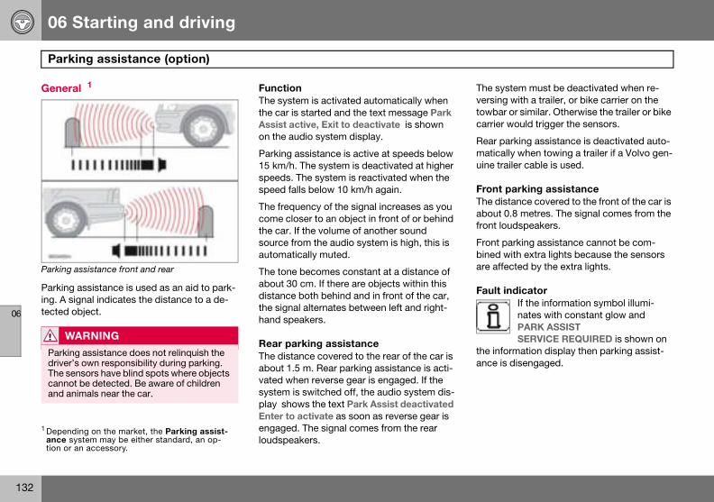
06 Starting and driving
132
Park
06
Genera
Parking a
Parkinging. A sitected o
The system must be deactivated when re-versing with a trailer, or bike carrier on the towbar or similar. Otherwise the trailer or bike carrier would trigger the sensors.
Rear parking assistance is deactivated auto-matically when towing a trailer if a Volvo gen-uine trailer cable is used.
Front parking assistanceThe distance covered to the front of the car is about 0.8 metres. The signal comes from the front loudspeakers.
Front parking assistance cannot be com-bined with extra lights because the sensors are affected by the extra lights.
Fault indicatorIf the information symbol illumi-nates with constant glow and PARK ASSIST SERVICE REQUIRED is shown on
the information display then parking assist-ance is disengaged.
1 Dependance sytion or a
W
Parkindriver’The secannotand an
ing assistance (option)
l 1
ssistance front and rear
assistance is used as an aid to park-gnal indicates the distance to a de-bject.
FunctionThe system is activated automatically when the car is started and the text message Park Assist active, Exit to deactivate is shown on the audio system display.
Parking assistance is active at speeds below 15 km/h. The system is deactivated at higher speeds. The system is reactivated when the speed falls below 10 km/h again.
The frequency of the signal increases as you come closer to an object in front of or behind the car. If the volume of another sound source from the audio system is high, this is automatically muted.
The tone becomes constant at a distance of about 30 cm. If there are objects within this distance both behind and in front of the car, the signal alternates between left and right-hand speakers.
Rear parking assistanceThe distance covered to the rear of the car is about 1.5 m. Rear parking assistance is acti-vated when reverse gear is engaged. If the system is switched off, the audio system dis-play shows the text Park Assist deactivated Enter to activate as soon as reverse gear is engaged. The signal comes from the rear loudspeakers.
ing on the market, the Parking assist-stem may be either standard, an op-n accessory.
ARNING
g assistance does not relinquish the s own responsibility during parking. nsors have blind spots where objects be detected. Be aware of children imals near the car.

06 Starting and driving
133
Parking assistance (option)
06
ActivatParkingpressingpage 68activatetem disptivated bpanel. Tactive E
W
Some false sclude hic brakand sncause
ing/deactivating assistance can be deactivated by EXIT on the control panel, see . Park Assist deactivated Enter to will then appear on the audio sys-lay. Parking assistance can be reac-y pressing ENTER on the control
he display then shows Park Assist xit to deactivate.
Cleaning the sensors
Parking assistance sensors
The sensors must be cleaned regularly to en-sure that they work properly. Clean them with water and car shampoo.
ARNING
sources may deceive the system with ignals. Examples of such sources in-orns, wet tyres on asphalt, pneumat-
es and motorcycle exhaust pipes. Ice ow covering the sensors may also false warning signals.
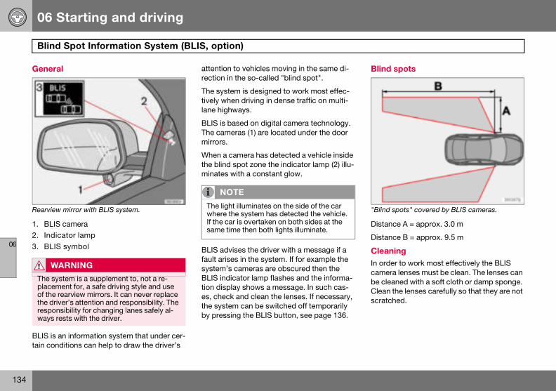
06 Starting and driving
134
Blind
06
Genera
Rearview
1. BLIS2. Indic3. BLIS
BLIS is atain con
Blind spots
"Blind spots" covered by BLIS cameras.
Distance A = approx. 3.0 m
Distance B = approx. 9.5 m
CleaningIn order to work most effectively the BLIS camera lenses must be clean. The lenses can be cleaned with a soft cloth or damp sponge. Clean the lenses carefully so that they are not scratched.
W
The syplacemof the rthe drivresponways r
Spot Information System (BLIS, option)
l
mirror with BLIS system.
camera ator lamp symbol
n information system that under cer-ditions can help to draw the driver’s
attention to vehicles moving in the same di-rection in the so-called "blind spot".
The system is designed to work most effec-tively when driving in dense traffic on multi-lane highways.
BLIS is based on digital camera technology. The cameras (1) are located under the door mirrors.
When a camera has detected a vehicle inside the blind spot zone the indicator lamp (2) illu-minates with a constant glow.
BLIS advises the driver with a message if a fault arises in the system. If for example the system’s cameras are obscured then the BLIS indicator lamp flashes and the informa-tion display shows a message. In such cas-es, check and clean the lenses. If necessary, the system can be switched off temporarily by pressing the BLIS button, see page 136.
ARNING
stem is a supplement to, not a re-ent for, a safe driving style and use earview mirrors. It can never replace er’s attention and responsibility. The sibility for changing lanes safely al-ests with the driver.
NOTE
The light illuminates on the side of the car where the system has detected the vehicle. If the car is overtaken on both sides at the same time then both lights illuminate.
06 Starting and driving
135
nformation System (BLIS, option)
06
When BThe sysat a spe
OvertaThe systake ano10 km/h
The sysovertake70 km/h
DaylighIn dayligthe surr
IM
The lenor snowfrom th
W
BLIS dBLIS ding.A wideceal otprevenfrom b
WARNING
The system does not react to bicycles or mopeds.The BLIS cameras can be disrupted by in-tensive light or when driving in the dark when there are no light sources (e.g. street lighting or other vehicles). The system may then interpret the lack of light as if the cam-eras have been blocked.In both cases a message is shown on the information display.When driving in such conditions system performance may be temporarily reduced and a text message is shown, see page 136. If the message disappears automatically then BLIS has returned to normal function-ality. The BLIS cameras have limitations similar to the human eye, i.e. they "see" worse in heavy snowfall or thick fog for example.
Blind Spot I
LIS operatestem operates when the car is driven ed above 10 km/h.
kingtem is designed to react if you over-ther vehicle at a speed of up to faster than the other vehicle.
tem is designed to react if you are n by a vehicle travelling up to faster than your vehicle.
t and darknessht the system reacts to the shape of
ounding vehicles. The system is de-
signed to detect motor vehicles such as cars, trucks, buses and motorcycles.
In darkness the system reacts to the head-lamps of surrounding vehicles. Vehicles with headlamps that are switched off are not de-tected by the system. This means for exam-ple that the system does not react to a trailer without headlamps which is towed behind a car or truck.
PORTANT
ses are electrically heated to melt ice . If necessary, brush snow away
e lenses.
ARNING
oes not work in sharp bends.oes not work when the car is revers-
trailer coupled to the car can con-her vehicles in adjacent lanes. It can t the vehicle in the screened area eing detected by BLIS.

06 Starting and driving
136
Blind
06
Activat
Button fo
BLIS is aThe indithree tim
The syspressing
When Bton goesthe dash
When Billuminathe dispdoor pa
Spot Information System (BLIS, option)
ing/deactivating
r activating/deactivating.
ctivated when the engine is started. cator lamps in the door panels flash es when BLIS is activated.
tem can be deactivated/activated by BLIS.
LIS is deactivated the light in the but- out and a text message is shown on board display.
LIS is activated the light in the button tes, a new text message is shown on lay and the indicator lamps in the nels flash three times. Press the
READ button to clear the text message. For more information on messages, see page 47.
BLIS system message
Text on the display
System status
BLIND-SPOT SYST SERVICE REQUIRED
Blind spot syst. disen-gaged. Contact an authorised Volvo workshop.
BLIS FUNCTION REDUCED
Reduced function.
BLIND-SPOT SYST CAMERA BLOCKED
One or both cameras blocked. Clean the lenses.
BLIND-SPOT INFO SYSTEM OFF
BLIS system off.
BLIND-SPOT INFO SYSTEM ON
BLIS system on.
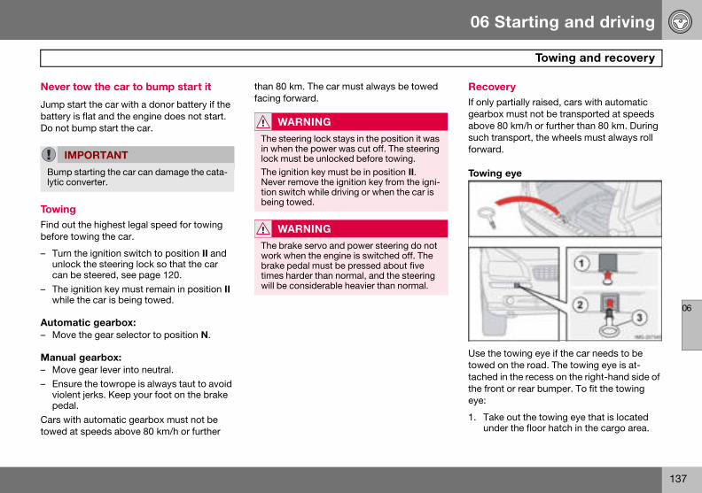
06 Starting and driving
137
Towing and recovery
06
Never t
Jump stbattery Do not b
TowingFind outbefore t
– Turn unloccan b
– The igwhile
Automa– Move
Manua– Move– Ensu
violenpeda
Cars wittowed a
RecoveryIf only partially raised, cars with automatic gearbox must not be transported at speeds above 80 km/h or further than 80 km. During such transport, the wheels must always roll forward.
Towing eye
Use the towing eye if the car needs to be towed on the road. The towing eye is at-tached in the recess on the right-hand side of the front or rear bumper. To fit the towing eye:
1. Take out the towing eye that is located under the floor hatch in the cargo area.
IM
Bump lytic co
ow the car to bump start it
art the car with a donor battery if the is flat and the engine does not start. ump start the car.
the highest legal speed for towing owing the car.
the ignition switch to position II and k the steering lock so that the car e steered, see page 120.nition key must remain in position II
the car is being towed.
tic gearbox: the gear selector to position N.
l gearbox: gear lever into neutral.re the towrope is always taut to avoid t jerks. Keep your foot on the brake
l.h automatic gearbox must not be t speeds above 80 km/h or further
than 80 km. The car must always be towed facing forward.
PORTANT
starting the car can damage the cata-nverter.
WARNING
The steering lock stays in the position it was in when the power was cut off. The steering lock must be unlocked before towing.The ignition key must be in position II. Never remove the ignition key from the igni-tion switch while driving or when the car is being towed.
WARNING
The brake servo and power steering do not work when the engine is switched off. The brake pedal must be pressed about five times harder than normal, and the steering will be considerable heavier than normal.
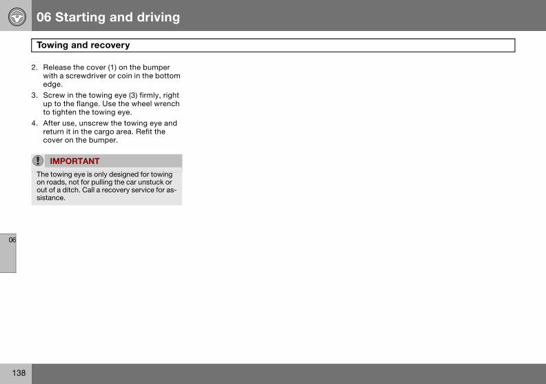
06 Starting and driving
138
Towi
06
2. Relewithedge
3. Screup toto tig
4. Afteretucove
IM
The toon roaout of sistanc
ng and recovery
ase the cover (1) on the bumper a screwdriver or coin in the bottom .w in the towing eye (3) firmly, right the flange. Use the wheel wrench hten the towing eye.
r use, unscrew the towing eye and rn it in the cargo area. Refit the r on the bumper.
PORTANT
wing eye is only designed for towing ds, not for pulling the car unstuck or a ditch. Call a recovery service for as-e.
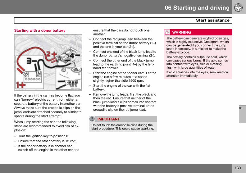
06 Starting and driving
139
Start assistance
06
Startin
If the bacan "boseparateAlways jump leasparks d
When justeps arplosion:
– Turn – Ensu– If the
switc
WARNING
The battery can generate oxyhydrogen gas, which is highly explosive. One spark, which can be generated if you connect the jump leads incorrectly, is sufficient to make the battery explode.The battery contains sulphuric acid, which can cause serious burns. If the acid comes into contact with eyes, skin or clothing, flush with large quantities of water.If acid splashes into the eyes, seek medical attention immediately.
g with a donor battery
ttery in the car has become flat, you rrow" electric current from either a battery or the battery in another car.
make sure the crocodile clips on the ds are attached securely to eliminate uring the start attempt.
mp starting the car, the following e recommended to avoid risk of ex-
the ignition key to position 0.re that the other battery is 12 volt. donor battery is in another car, h off the engine in the other car and
ensure that the cars do not touch one another.
– Connect the red jump lead between the positive terminal on the donor battery (1+) and the one in your car (2+).
– Connect one end of the black jump lead to the donor battery’s negative terminal (3-).
– Connect the other end of the black jump lead to the earthing point (4–) by the left-hand strut tower.
– Start the engine of the "donor car". Let the engine run a few minutes at a speed slightly higher than idle 1500 rpm.
– Start the engine of the car with the flat battery.
– Remove the jump leads, first the black and then the red. Ensure that neither of the black jump lead’s clips comes into contact with the battery’s positive terminal or the crocodile clip on the red jump lead.
IMPORTANT
Do not touch the crocodile clips during the start procedure. This could cause sparking.
06 Starting and driving
140
Drivi
06
Genera
The loadsories mload carcombinethe towbreducedtheir we
If the towised Volered witing with
• The cappro
• If theVolvofor dr
• Distriweighspec
• Incremendpress
• Cleantowb
Trailer weightsInformation on permitted trailer weights, see page 233.
1 Does noliser hit
WARNING
Follow the stated recommendations for trailer weights. Otherwise, the rig may be difficult to control during evasive manoeu-vres and braking.
NOTE
The stated maximum permitted trailer weights are those permitted by Volvo. Na-tional vehicle regulations can further limit trailer weights and speeds. Towbars can be certified for higher towing weights than the car can actually tow.
ng with a trailer
l
capacity is affected by extra acces-ounted on the car, such as a towbar, riers, space box, the passengers’ d weight etc. as well as the load on all. The load capacity of the car is by the number of passengers and ight.
ing bracket is fitted by an author-vo workshop, then the car is deliv-h the necessary equipment for driv- a trailer.
ar’s towing bracket must be of an ved type.
towbar is retrofitted, check with your dealer that the car is fully equipped iving with a trailer.bute the load on the trailer so that the t on the towing bracket follows the
ified maximum towball load.ase the tyre pressure to the recom-ed pressure for a full load. For tyre ure decal location, see page 158. the towbar regularly and grease the
all1.
• Do not tow a heavy trailer when the car is brand new. Wait until it has been driven at least 1000 km.
• The brakes are loaded much more than usual on long and steep downhill slopes. Downshift to a lower gear and adjust your speed.
• The engine is loaded more heavily than usual when driving with a trailer.
• The engine and gearbox can overheat if the car is driven with a heavy load in hot weather. If the temperature gauge for the engine’s cooling system goes into the red zone, stop and let the engine idle for a few minutes. The automatic gearbox responds through a built-in protection system. See the message on the information display. If the car overheats, the air conditioning may be switched off temporarily.
• In the interests of safety, speed should be restricted to 80 km/h, even if the laws of certain countries allow for higher speeds.
• Move the gear selector to parking position P when parking an automatic car with a hitched trailer. Always use the park-ing brake. Block the wheels with chocks when parking a car with hitched trailer on a hill.
t apply to the towball if using a stabi-ch.
06 Starting and driving
141
Driving with a trailer
06
Automtrailer
Parking1. App2. Mov
posi
Startin1. Mov
posi2. Rele
Steep i• Selec
tion wspeechancoole
• Do noenginnomi
• Avoidmore
atic gearbox, driving with a
on a hillly the parking brake (handbrake).e the gear selector to parking tion P.
g on a hille the gear selector to driving tion D.ase the parking brake (handbrake).
nclinest an appropriate manual gear posi-hen climbing steep inclines or at low
ds. This prevents the gearbox from ging up and keeps the gearbox oil r.t use a higher manual gear than the e can "handle". It is not always eco-cal to drive in high gears. driving with a trailer on inclines of than 15 %.
Diesel 1.6D engine with manual gearbox, driving with a trailerIf the car is driven with a major load in a hot climate, the engine cooling fan can be re-placed with one of a greater capacity than the standard model. Check with your nearest Volvo dealer regarding the options for your car.
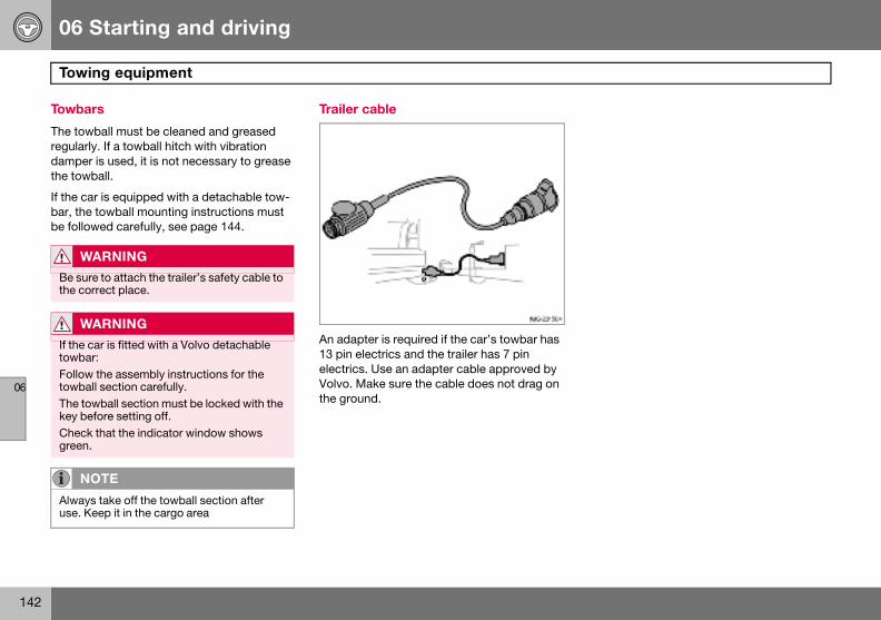
06 Starting and driving
142
Towi
06
Towbar
The towregularlydamperthe towb
If the cabar, thebe follow
W
Be surthe cor
W
If the ctowbarFollowtowbalThe towkey beCheckgreen.
NO
Alwaysuse. Ke
ng equipment
s
ball must be cleaned and greased . If a towball hitch with vibration
is used, it is not necessary to grease all.
r is equipped with a detachable tow- towball mounting instructions must
ed carefully, see page 144.
Trailer cable
An adapter is required if the car’s towbar has 13 pin electrics and the trailer has 7 pin electrics. Use an adapter cable approved by Volvo. Make sure the cable does not drag on the ground.
ARNING
e to attach the trailer’s safety cable to rect place.
ARNING
ar is fitted with a Volvo detachable : the assembly instructions for the l section carefully.ball section must be locked with the
fore setting off. that the indicator window shows
TE
take off the towball section after ep it in the cargo area

06 Starting and driving
143
Towing equipment
06
Specifi
Dimens
I J K
Fixed t113
100 140Fixed t
Detach63
Detach
cations
ions for mounting points (mm)
A B C D E F G H
owbar standard 1104 90
964 482 40 141 542 150owbar with Nivomat 1100 96
able towbar standard 1104 90
able towbar with Nivomat 1100 96
1 Side member
2 Ball centre
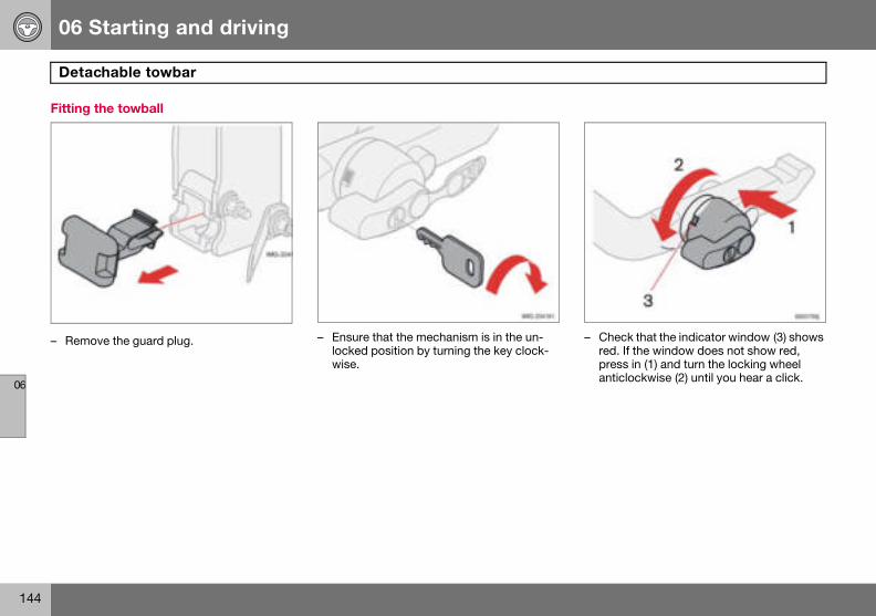
06 Starting and driving
144
Deta
06
Fitting
– Remo – Check that the indicator window (3) shows red. If the window does not show red, press in (1) and turn the locking wheel anticlockwise (2) until you hear a click.
chable towbar
the towball
ve the guard plug. – Ensure that the mechanism is in the un-locked position by turning the key clock-wise.
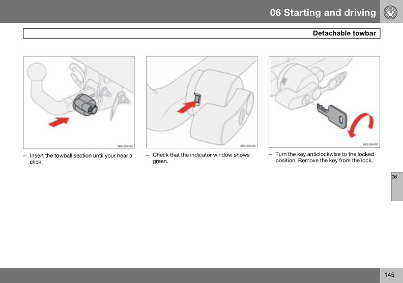
06 Starting and driving
145
Detachable towbar
06
– Inserclick.
– Turn the key anticlockwise to the locked position. Remove the key from the lock.
t the towball section until your hear a – Check that the indicator window shows green.
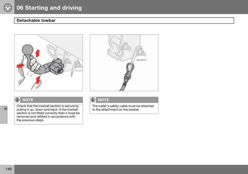
06 Starting and driving
146
Deta
06
NO
Checkpullingsectionremovthe pre
chable towbar
TE
that the towball section is secure by it up, down and back. If the towball is not fitted correctly then it must be
ed and refitted in accordance with vious steps
NOTE
The trailer’s safety cable must be attached to the attachment on the towbar.
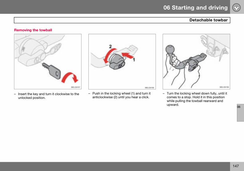
06 Starting and driving
147
Detachable towbar
06
Remov
– Inserunloc
– Turn the locking wheel down fully, until it comes to a stop. Hold it in this position while pulling the towball rearward and upward.
ing the towball
t the key and turn it clockwise to the ked position.
– Push in the locking wheel (1) and turn it anticlockwise (2) until you hear a click.

06 Starting and driving
148
Deta
06
– Inser
chable towbar
t the guard plug.
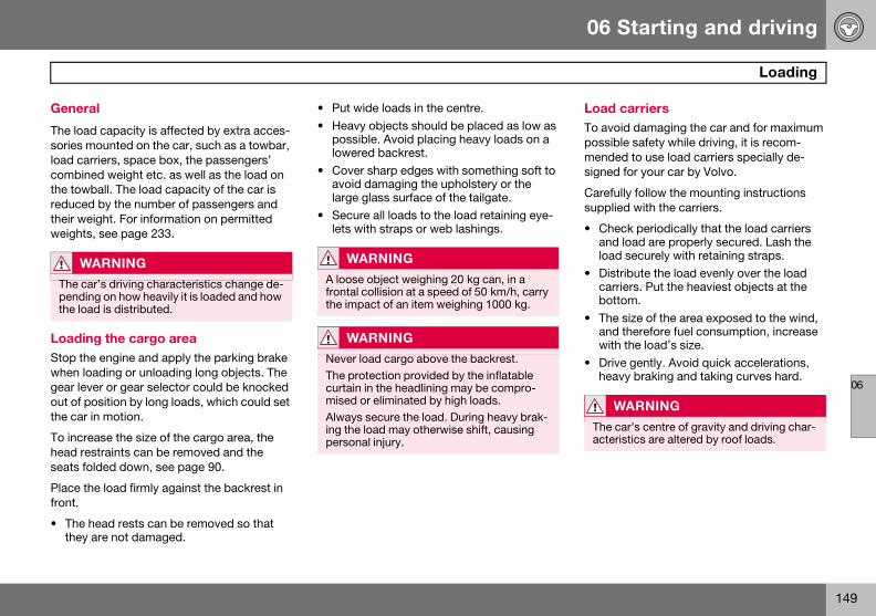
06 Starting and driving
149
Loading
06
Genera
The loadsories mload carcombinethe towbreducedtheir weweights
LoadinStop thewhen logear levout of pothe car i
To increhead resseats fo
Place thfront.
• The hthey a
Load carriersTo avoid damaging the car and for maximum possible safety while driving, it is recom-mended to use load carriers specially de-signed for your car by Volvo.
Carefully follow the mounting instructions supplied with the carriers.
• Check periodically that the load carriers and load are properly secured. Lash the load securely with retaining straps.
• Distribute the load evenly over the load carriers. Put the heaviest objects at the bottom.
• The size of the area exposed to the wind, and therefore fuel consumption, increase with the load’s size.
• Drive gently. Avoid quick accelerations, heavy braking and taking curves hard.
W
The capendinthe loa
WARNING
The car’s centre of gravity and driving char-acteristics are altered by roof loads.
l
capacity is affected by extra acces-ounted on the car, such as a towbar, riers, space box, the passengers’ d weight etc. as well as the load on all. The load capacity of the car is by the number of passengers and ight. For information on permitted , see page 233.
g the cargo area engine and apply the parking brake
ading or unloading long objects. The er or gear selector could be knocked sition by long loads, which could set
n motion.
ase the size of the cargo area, the traints can be removed and the
lded down, see page 90.
e load firmly against the backrest in
ead rests can be removed so that re not damaged.
• Put wide loads in the centre.• Heavy objects should be placed as low as
possible. Avoid placing heavy loads on a lowered backrest.
• Cover sharp edges with something soft to avoid damaging the upholstery or the large glass surface of the tailgate.
• Secure all loads to the load retaining eye-lets with straps or web lashings.
ARNING
r’s driving characteristics change de-g on how heavily it is loaded and how d is distributed.
WARNING
A loose object weighing 20 kg can, in a frontal collision at a speed of 50 km/h, carry the impact of an item weighing 1000 kg.
WARNING
Never load cargo above the backrest. The protection provided by the inflatable curtain in the headlining may be compro-mised or eliminated by high loads.Always secure the load. During heavy brak-ing the load may otherwise shift, causing personal injury.
06 Starting and driving
150
Adju
06
Correchand tr
A. HeadlB. Right-
The heato avoidpattern
Bi-Xenon headlamps
The headlamp control should be in position (A) for left-hand traffic and position (B) for right-hand traffic.
WARNING
On cars with Bi-Xenon headlamps the re-placement must be carried out by an au-thorised Volvo workshop. The headlamps must be handled with extreme care due to the high-voltage unit in the Xenon lamp.
sting headlamp pattern
t light pattern for left or right-affic
amp pattern for left-hand traffic. hand traffic.
dlamps’ projection can be adjusted dazzling other motorists. The correct will also better illuminate the verge.
Halogen headlamps
The headlamp control should be in position (A) for left-hand traffic and position (B) for right-hand traffic.
06 Starting and driving
151
06
152
General................................................................................................... 154Tyre pressure .......................................................................................... 158Warning triangle and spare wheel.......................................................... 160Changing wheels.................................................................................... 161Emergency puncture repair .................................................................... 163

07WHEELS AND TYRES
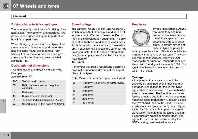
07 Wheels and tyres
154
Gene
07
Driving
The tyreacteristipressurehow the
When chsame tyalso thewheels.sures spsee pag
DesignThe dimExample205/55R
New tyresTyres are perishable. After a few years they begin to harden at the same time as the friction capacity/char-acteristics gradually deteri-orate. Therefore aim to get as fresh tyres as possible
when you replace them. This is especially im-portant with regard to winter tyres. The week and year of manufacture, the tyre’s DOT marking (Department of Transportation), are stated with four digits, for example 1502. The tyre in the illustration was manufactured in week 15 of 2002.
Tyre ageAll tyres older than six years should be checked by an expert even if they seem un-damaged. The reason for this is that tyres age and decompose, even if they are hardly ever or never used. The function can there-fore be affected due to the tyre’s constituent materials being broken down. In such a case the tyre should then not be used. This also applies to spare tyres, winter tyres and tyres saved for future use. Examples of external signs which indicate that the tyre is unsuita-ble for use are cracks or discoloration. The age of the tyre can be determined by the DOT marking, see illustration above.
20555
R1691W
ral
characteristics and tyres
s greatly affect the car’s driving char-cs. The type of tyre, dimensions, tyre and speed rating are important for
car performs.
anging tyres, ensure that tyres of the pe and dimensions, and preferably same make, are fitted to all four Follow the recommended tyre pres-ecified on the tyre pressure label, e 158.
ation of dimensions ensions are stated on all car tyres. : 16 91 W.
Speed ratings The car has "Whole Vehicle Type Approval", which means that dimensions and speed rat-ings must not differ from those specified on the vehicle’s registration document. The only exception to these conditions is winter tyres (both those with metal studs and those with-out). If such a tyre is chosen, the car must not be driven faster than the speed rating of the tyre (for example, class Q can be driven at a maximum of 160 km/h).
Remember that traffic regulations determine how fast a car can be driven, not the speed class of the tyres.
Note! Maximum permitted speeds indicated.Section width (mm)Ratio between section height and width (%)Radial plyRim diameter in inches (")Tyre load index (in this case 615 kg)Speed rating (in this case 270 km/h).
Q 160 km/h (used only on winter tyres)T 190 km/hH 210 km/hV 240 km/hW 270 km/hY 300 km/h
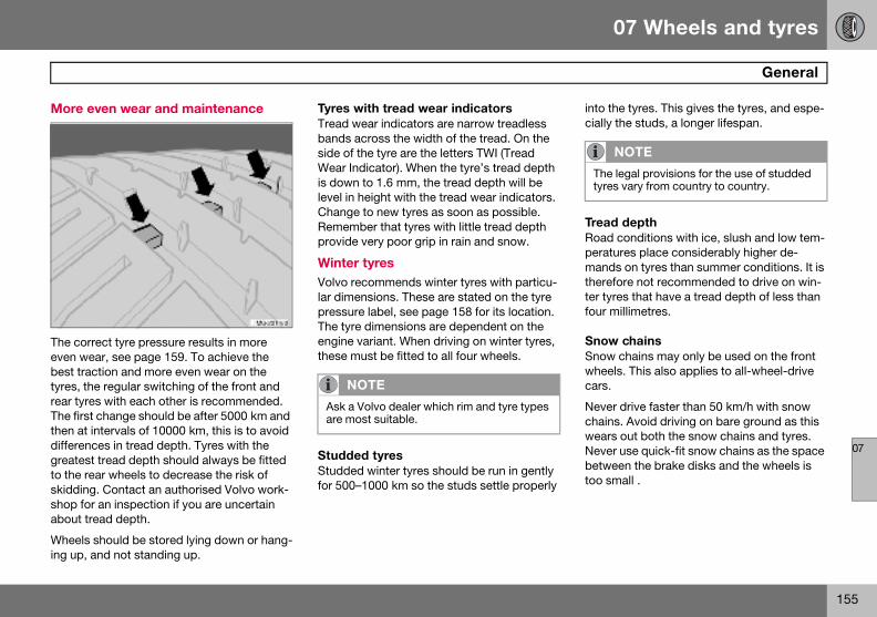
07 Wheels and tyres
155
General
07
More e
The correven webest tratyres, threar tyreThe firstthen at idifferencgreatestto the reskiddingshop forabout tr
Wheels ing up, a
into the tyres. This gives the tyres, and espe-cially the studs, a longer lifespan.
Tread depthRoad conditions with ice, slush and low tem-peratures place considerably higher de-mands on tyres than summer conditions. It is therefore not recommended to drive on win-ter tyres that have a tread depth of less than four millimetres.
Snow chainsSnow chains may only be used on the front wheels. This also applies to all-wheel-drive cars.
Never drive faster than 50 km/h with snow chains. Avoid driving on bare ground as this wears out both the snow chains and tyres. Never use quick-fit snow chains as the space between the brake disks and the wheels is too small .
NOTE
The legal provisions for the use of studded tyres vary from country to country.
ven wear and maintenance
ect tyre pressure results in more ar, see page 159. To achieve the
ction and more even wear on the e regular switching of the front and s with each other is recommended. change should be after 5000 km and ntervals of 10000 km, this is to avoid es in tread depth. Tyres with the tread depth should always be fitted ar wheels to decrease the risk of . Contact an authorised Volvo work- an inspection if you are uncertain ead depth.
should be stored lying down or hang-nd not standing up.
Tyres with tread wear indicators Tread wear indicators are narrow treadless bands across the width of the tread. On the side of the tyre are the letters TWI (Tread Wear Indicator). When the tyre’s tread depth is down to 1.6 mm, the tread depth will be level in height with the tread wear indicators. Change to new tyres as soon as possible. Remember that tyres with little tread depth provide very poor grip in rain and snow.
Winter tyres Volvo recommends winter tyres with particu-lar dimensions. These are stated on the tyre pressure label, see page 158 for its location. The tyre dimensions are dependent on the engine variant. When driving on winter tyres, these must be fitted to all four wheels.
Studded tyresStudded winter tyres should be run in gently for 500–1000 km so the studs settle properly
NOTE
Ask a Volvo dealer which rim and tyre types are most suitable.
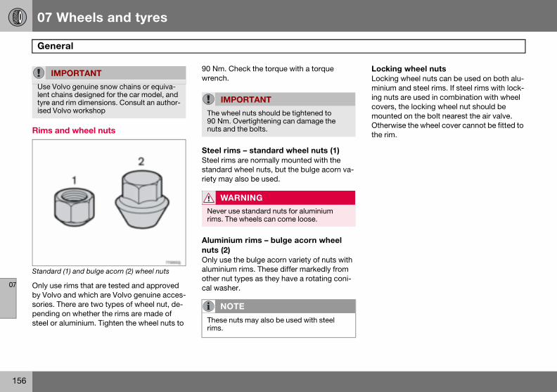
07 Wheels and tyres
156
Gene
07
Rims a
Standard
Only useby Volvosories. Tpendingsteel or
Locking wheel nutsLocking wheel nuts can be used on both alu-minium and steel rims. If steel rims with lock-ing nuts are used in combination with wheel covers, the locking wheel nut should be mounted on the bolt nearest the air valve. Otherwise the wheel cover cannot be fitted to the rim.
IM
Use Volent chtyre anised Vo
ral
nd wheel nuts
(1) and bulge acorn (2) wheel nuts
rims that are tested and approved and which are Volvo genuine acces-here are two types of wheel nut, de- on whether the rims are made of aluminium. Tighten the wheel nuts to
90 Nm. Check the torque with a torque wrench.
Steel rims – standard wheel nuts (1)Steel rims are normally mounted with the standard wheel nuts, but the bulge acorn va-riety may also be used.
Aluminium rims – bulge acorn wheel nuts (2)Only use the bulge acorn variety of nuts with aluminium rims. These differ markedly from other nut types as they have a rotating coni-cal washer.
PORTANT
lvo genuine snow chains or equiva-ains designed for the car model, and d rim dimensions. Consult an author-lvo workshop
IMPORTANT
The wheel nuts should be tightened to 90 Nm. Overtightening can damage the nuts and the bolts.
WARNING
Never use standard nuts for aluminium rims. The wheels can come loose.
NOTE
These nuts may also be used with steel rims.
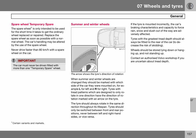
07 Wheels and tyres
157
General
07
Spare wThe spafor the swheel respare wmal wheby the u
Never dwheel o
If the tyre is mounted incorrectly, the car’s braking characteristics and capacity to force rain, snow and slush out of the way are ad-versely affected.
Tyres with the greatest tread depth should al-ways be fitted to the rear of the car (to de-crease the risk of skidding).
Wheels should be stored lying down or hang-ing up, and not standing up.
Contact an authorised Volvo workshop if you are uncertain about tread depth.
1 Certain
IM
The camore t
heel Temporary Spare re wheel1 is only intended to be used hort time it takes to get the ordinary placed or repaired. Replace the heel as soon as possible with a nor-el. The car’s handling may be altered se of the spare wheel.
rive faster than 80 km/h with a spare n the car.
Summer and winter wheels
The arrow shows the tyre’s direction of rotation
When summer and winter wheels are changed they should be marked with which side of the car they were mounted on, for ex-ample L for left and R for right. Tyres with tread patterns which are designed to only ro-tate in one direction have the direction of ro-tation marked with an arrow on the tyre.
The tyre should always rotate in the same di-rection throughout its lifespan. Tyres should only be switched between front and rear po-sitions, never between left and right-hand sides, or vice versa.
variants and markets.
PORTANT
r must never be driven fitted with han one "Temporary Spare" wheel.
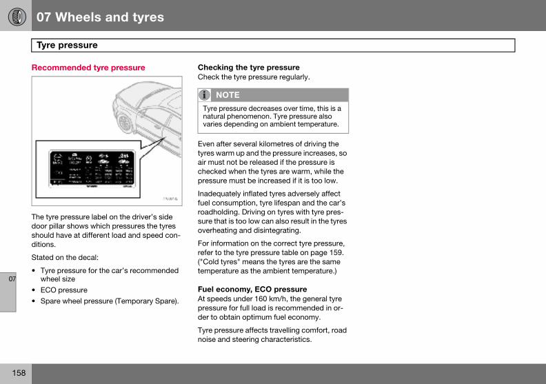
07 Wheels and tyres
158
Tyre
07
Recom
The tyredoor pillshould hditions.
Stated o
• Tyre whee
• ECO • Spare
pressure
mended tyre pressure
pressure label on the driver’s side ar shows which pressures the tyres ave at different load and speed con-
n the decal:
pressure for the car’s recommended l sizepressure wheel pressure (Temporary Spare).
Checking the tyre pressureCheck the tyre pressure regularly.
Even after several kilometres of driving the tyres warm up and the pressure increases, so air must not be released if the pressure is checked when the tyres are warm, while the pressure must be increased if it is too low.
Inadequately inflated tyres adversely affect fuel consumption, tyre lifespan and the car’s roadholding. Driving on tyres with tyre pres-sure that is too low can also result in the tyres overheating and disintegrating.
For information on the correct tyre pressure, refer to the tyre pressure table on page 159. ("Cold tyres" means the tyres are the same temperature as the ambient temperature.)
Fuel economy, ECO pressure At speeds under 160 km/h, the general tyre pressure for full load is recommended in or-der to obtain optimum fuel economy.
Tyre pressure affects travelling comfort, road noise and steering characteristics.
NOTE
Tyre pressure decreases over time, this is a natural phenomenon. Tyre pressure also varies depending on ambient temperature.
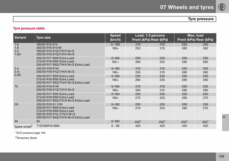
07 Wheels and tyres
159
Tyre pressure
07
Tyre pr
VarianpersonsRear (kPa)
Max. loadFront (kPa) Rear (kPa)
1.61.82.01.6D
210 250 250210 280 260
220 250 250220 280 260
2.42.4i2.0D
210 250 250210 280 260220 250 250220 280 260
T5 210 250 250210 280 260220 250 250220 290 270
D5 220 250 250220 290 270
All 2501 2501 2501
Spare w 420 420 420
1ECO p2Tempo
essure table
t Tyre sizeSpeed (km/h)
Load, 1-3 Front (kPa)
195/65 R15 91V 205/55 R16 91V/W 195/65 R15 91Q/T/H/V M+S 205/55 R16 91Q/T/H/V M+S
0 –160 210160+ 250
205/50 R17 93W Extra Load 215/45 R18 93W Extra Load 205/50 R17 93Q/T/H/V M+S Extra Load
0–160 220160 + 260
205/55 R16 91W 205/55 R16 91Q/T/H/V M+S
0–160 210160+ 250
205/50 R17 93W Extra Load 215/45 R18 93W Extra Load 205/50 R17 93Q/T/H/V M+S Extra Load
0–160 220160+ 260
205/55 R16 91W 205/55 R16 91Q/T/H/V M+S
0–160 210160+ 260
205/50 R17 93W Extra Load 215/45 R18 93W Extra Load 205/50 R17 93Q/T/H/V M+S Extra Load
0–160 220160+ 270
205/55 R16 91 V/W 205/50 R17 93W Extra Load 215/45 R18 93W Extra Load 205/55 R16 91Q /T/H/V M+S 205/50 R17 93Q/T/H/V M+S Extra Load
0–160 230160+ 270
All 0–160 2501
heel2 T125/85R16 99M 0 – 80 420
ressure page 158
rary Spare
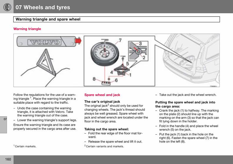
07 Wheels and tyres
160
Warn
07
Warnin
Follow ting triansuitable
– Undotriangthe w
– LoweEnsure tproperly
– Take out the jack and the wheel wrench.
Putting the spare wheel and jack into the cargo area:– Crank the jack (1) to halfway. The marking
on the plate (2) should line up with the marking on the arm (3) so that the jack can fit lying down in the holder.
– Fold in the handle (4) and place the wheel wrench (5) on the jack.
– Put the jack (1) back in the hole on the right (6). Fasten the spare wheel (7) in the hole on the left (8).
1 Certain
ing triangle and spare wheel
g triangle
he regulations for the use of a warn-gle 1. Place the warning triangle in a place with regard to the traffic.
the case containing the warning le, it is attached with Velcro. Take arning triangle out of the case.r the warning triangle’s support legs.he warning triangle and its case are secured in the cargo area after use.
Spare wheel and jack
The car’s original jackThe original jack2 should only be used for changing wheels. The jack’s thread should always be well greased. Spare wheel with jack and wheel wrench are located under the floor in the cargo area.
Taking out the spare wheel:– Fold the rear edge of the floor mat for-
ward.– Release the spare wheel and lift it out.
markets. 2 Certain variants and markets.
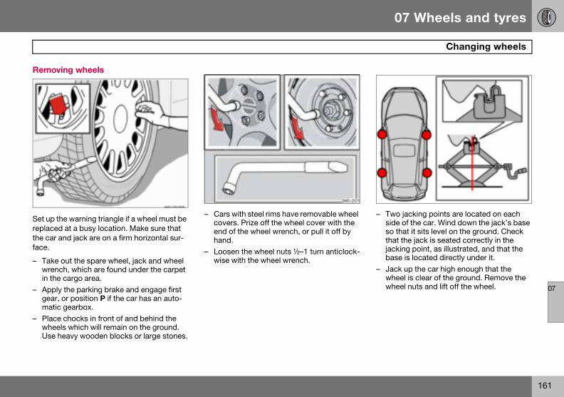
07 Wheels and tyres
161
Changing wheels
07
Remov
Set up treplacedthe car aface.
– Takewrenin the
– Applygear,matic
– PlacewheeUse h
– Two jacking points are located on each side of the car. Wind down the jack’s base so that it sits level on the ground. Check that the jack is seated correctly in the jacking point, as illustrated, and that the base is located directly under it.
– Jack up the car high enough that the wheel is clear of the ground. Remove the wheel nuts and lift off the wheel.
ing wheels
he warning triangle if a wheel must be at a busy location. Make sure that nd jack are on a firm horizontal sur-
out the spare wheel, jack and wheel ch, which are found under the carpet cargo area. the parking brake and engage first
or position P if the car has an auto- gearbox. chocks in front of and behind the ls which will remain on the ground. eavy wooden blocks or large stones.
– Cars with steel rims have removable wheel covers. Prize off the wheel cover with the end of the wheel wrench, or pull it off by hand.
– Loosen the wheel nuts ½–1 turn anticlock-wise with the wheel wrench.
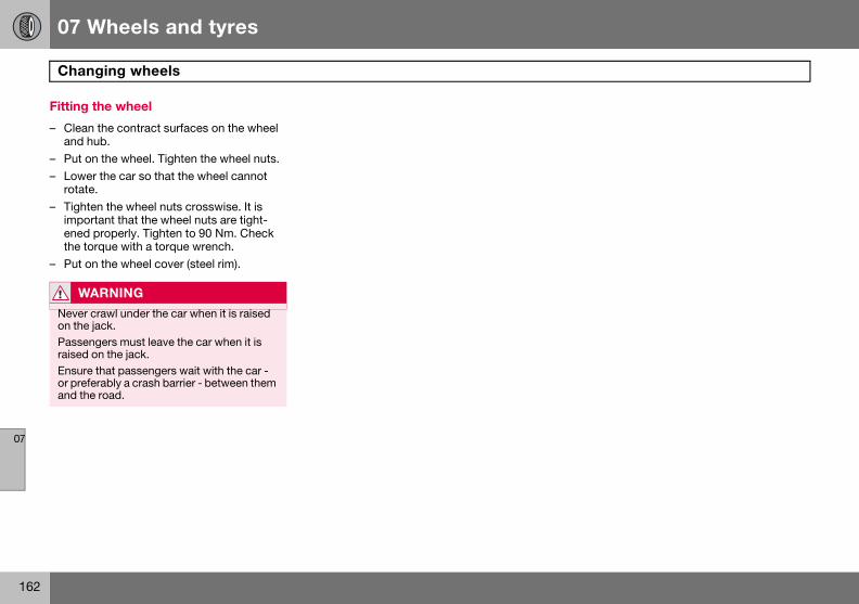
07 Wheels and tyres
162
Chan
07
Fitting
– Cleanand h
– Put o– Lowe
rotate– Tight
impoenedthe to
– Put o
W
Never on the Passenraised Ensureor prefand th
ging wheels
the wheel
the contract surfaces on the wheel ub.n the wheel. Tighten the wheel nuts.r the car so that the wheel cannot .
en the wheel nuts crosswise. It is rtant that the wheel nuts are tight- properly. Tighten to 90 Nm. Check rque with a torque wrench.n the wheel cover (steel rim).
ARNING
crawl under the car when it is raised jack.gers must leave the car when it is
on the jack. that passengers wait with the car - erably a crash barrier - between them e road.
07 Wheels and tyres
163
Emergency puncture repair
07
Genera
Cars whstead eqrepair kithe puncpressurecompresealing
The expiration date is located on the front of the compressor, see the illustration on page 168.
See page 168 for information on canister re-placement.
The emergency puncture repair kit has limit-ed abilities to seal tyres which have punc-
NO
The jacemerg
NOTE
The emergency puncture repair kit is only intended for sealing tyres with a puncture in the tread.
l
ich do not have a spare wheel are in-uipped with an emergency puncture
t. This kit can be used to both seal ture and to check and adjust the tyre . The kit consists of an electric air
ssor and an integrated canister with liquid.
Emergency puncture repair kitThe emergency puncture repair kit1 is only in-tended to work as a temporary repair so that the car can be driven a further 200 km (max.) or to the nearest tyre centre. The sealing fluid has the ability to effectively seal tyres which have punctures in the tread.
The sealing fluid canister should be replaced before its expiration date or after use of the puncture repair kit.
TE
k is an option on cars equipped with ency puncture repair kit.
1 Certain variants and markets.
07 Wheels and tyres
164
Emer
07
tures in with thehave larlar dama
The emepressor the carg
12 V socby the cseat andtrical sotyre.
Taking repair k– Fold
forwa– Lift u
W
The secomescase ofluid w
gency puncture repair
the wall of the tyre. Do not seal tyres emergency puncture repair kit if they ger slits, cracks, irregularities or simi-ge.
rgency puncture repair kit with com-and tools are found under the floor in o area.
kets for the compressor are located entre console in the front, by the rear in the cargo area. Choose the elec-
cket that is nearest the punctured
out the emergency puncture it
away the rear edge of the floor mat rd.
p the emergency puncture repair kit.
ARNING
aling fluid may cause irritation if it into direct contact with skin. In the f contact with skin, wash away the ith soap and water.
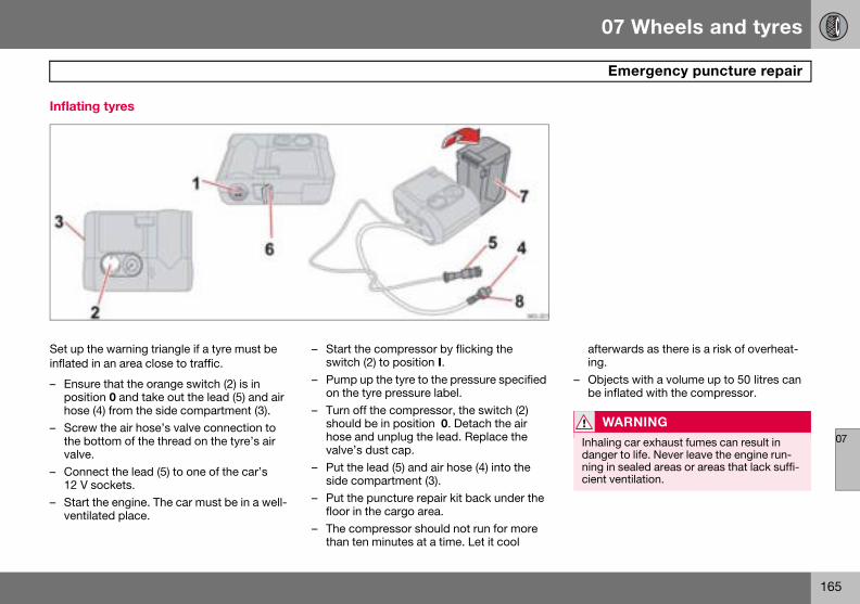
07 Wheels and tyres
165
Emergency puncture repair
07
Inflatin
Set up tinflated
– Ensuposithose
– Screwthe bvalve
– Conn12 V
– Start ventil
afterwards as there is a risk of overheat-ing.
– Objects with a volume up to 50 litres can be inflated with the compressor.
WARNING
Inhaling car exhaust fumes can result in danger to life. Never leave the engine run-ning in sealed areas or areas that lack suffi-cient ventilation.
g tyres
he warning triangle if a tyre must be in an area close to traffic.
re that the orange switch (2) is in ion 0 and take out the lead (5) and air (4) from the side compartment (3).
the air hose’s valve connection to ottom of the thread on the tyre’s air .ect the lead (5) to one of the car’s sockets.the engine. The car must be in a well-ated place.
– Start the compressor by flicking the switch (2) to position I.
– Pump up the tyre to the pressure specified on the tyre pressure label.
– Turn off the compressor, the switch (2) should be in position 0. Detach the air hose and unplug the lead. Replace the valve’s dust cap.
– Put the lead (5) and air hose (4) into the side compartment (3).
– Put the puncture repair kit back under the floor in the cargo area.
– The compressor should not run for more than ten minutes at a time. Let it cool
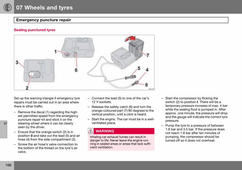
07 Wheels and tyres
166
Emer
07
Sealing
Set up trepairs mthere is
– Remoest ppuncsteerseen
– Ensuposithose
– Screwthe bvalve
– Start the compressor by flicking the switch (2) to position I. There will be a temporary pressure increase of max. 4 bar while the sealing fluid is pumped in. After approx. one minute, the pressure will drop and the gauge will indicate the correct tyre pressure.
– Pump the tyre to a pressure of between 1.8 bar and 3.5 bar. If the pressure does not reach 1.8 bar after ten minutes of pumping, the compressor should be turned off so it does not overheat.
gency puncture repair
punctured tyres
he warning triangle if emergency tyre ust be carried out in an area where
other traffic.
ve the decal (1) regarding the high-ermitted speed from the emergency ture repair kit and stick it on the ing wheel where it can be clearly by the driver.re that the orange switch (2) is in ion 0 and take out the lead (5) and air (4) from the side compartment (3).
the air hose’s valve connection to ottom of the thread on the tyre’s air .
– Connect the lead (5) to one of the car’s 12 V sockets.
– Release the safety catch (6) and turn the orange-coloured part (7) 90 degrees to the vertical position, until a click is heard.
– Start the engine. The car must be in a well-ventilated place.
WARNING
Inhaling car exhaust fumes can result in danger to life. Never leave the engine run-ning in sealed areas or areas that lack suffi-cient ventilation.

07 Wheels and tyres
167
Emergency puncture repair
07
– Undoand plead oranginal pKeepplace
– Immemuming flu
W
Never pressoant of tor othepressostanceContac
W
You shafter thused. Tchangedriving
IMPORTANT
The compressor should not run for more than ten minutes at a time. Let it cool after-wards as there is a risk of overheating.
NOTE
The canister with sealant and hose should be replaced after use.
the air hose (4) from the air valveut the dust cap back on. Unplug the (5) from the electrical socket. Fold the e-coloured part (7) back into its orig-osition and secure the catch (6). the emergency repair kit in a safe in the car.diately drive about 3 km, at a maxi- speed of 80 km/h, to allow the seal-id to seal the tyre well.
Check the tyre pressure again:
– Connect the air hose (4) to the air valve on the tyre. Connect the lead (5) to the 12 V power point. Read the pressure on the compressor. If the tyre pressure is below 1.3 bar, the tyre has not been sufficiently well sealed. The journey should not be continued under these circumstances. Contact a tyre centre.
– If the tyre pressure is higher than 1.3 bar, the tyre should be pumped up to the pressure stated on the tyre pressure label, see p. 158 for its location. Release pres-sure with the reduction valve (8) if the tyre pressure is too high.
– Turn off the compressor; the switch (2) should be in position 0. Detach the air hose and unplug the lead. Replace the valve’s dust cap.
– Put the lead (5) and air hose (4) into the side compartment (3).
– Put the puncture repair kit back under the floor in the cargo area.
ARNING
stand next to the tyre when the com-r is running. Be particularly observ-he tyre walls. If cracks, irregularities r damage appears, turn off the com-r immediately. Under these circum-s your journey should not continue. t an authorised tyre centre.
ARNING
ould not drive faster than 80 km/h e emergency tyre repair kit has been he temporarily sealed tyre must be d as soon as possible (maximum
distance: 200 km).
NOTE
Do not raise the orange-coloured part (7) when only the compressor is to be used for inflation.

07 Wheels and tyres
168
Emer
07
Chang
The canchangedpired, sebeen seholder (8changed
This chaised Volinstructi
– Check that the seal (7) on the new canister is not damaged. Screw the canister into place.
– Refit the case (3). Check that the case is correctly fitted. Screw it on with the screws (2).
– Affix the speed label (4) and new date label (1) to the tyre repair kit.
Treat the removed canister as hazardous waste.
IM
Read tof the c
gency puncture repair
ing the sealing fluid canister
ister of sealing fluid should be before the best-before date has ex-e date label (1), or after the tyre has
aled. After use, the canister (6) with ) and air hose (10) should be .
nge can be carried out by an author-vo workshop or following the ons.
Changing the canister before the best-before date has expired– Undo the two screws (2) on the orange-
coloured case (3).– Remove the speed label (4) and date
label (1), and open the safety catch (5). Loosen the case (3) and take it off.
– Unscrew and remove the canister (6).
PORTANT
he safety instructions on the bottom anister.
WARNING
Ensure the compressor is not connected to the 12 V socket when the canister is changed.
07 Wheels and tyres
169
Emergency puncture repair
07
Changiuse– Undo
colou– Remo
label Loos
– PushcanisRemo
– Pull o– Wipe
or sc– Fit a n
fitted– Chec
is notthe cuntil a
– Refit correscrew
– Affix label
The emped as no
ng the canister and hose after
the two screws (2) on the orange-red case (3).ve the speed label (4) and date (1), and open the safety catch (5). en the case (3) and take it off. down the button (8) while turning the ter (6) and the holder (9) clockwise. ve them.ut the air hose (10). off remaining sealing fluid with a rag rape it away if it is has already dried.ew air hose (10). Check that it is
correctly.k that the seal (7) on the new canister damaged. Screw the holder (9) onto anister (6) and turn it anticlockwise click is heard.
the case (3). Check that the case is ctly fitted. Screw it on with the s (2).
the speed label (4) and new date (1) to the tyre repair kit.ty canister and air hose can be treat-rmal waste.
170
Cleaning ................................................................................................. 172Touching up paintwork ........................................................................... 175Rustproofing .......................................................................................... 176
08CAR CARE
08 Car care
172
Clea
08
Washin
Wash thUse carto corro
• Do noWashcauseWashwater
• Thorothe c
• RinseWhenthat tnot cnot s
• Washplent
• If thecar u
• Dry tha wat
• Cleansoap
an automatic car wash cannot reach everywhere.
Press the brake pedal lightly from time to time if driving for long periods in rain or slush. This heats and dries the brake pads. You should also do this when you begin driving in extremely damp or cold weather.
Exterior plastic partsA special cleaning agent, available from Vol-vo dealers, is recommended for cleaning ex-terior plastic parts. Never use strong stain re-movers.
W
Alwaysshop. Thot.
WARNING
Always test the brakes after washing the car to ensure that moisture and corrosion do not attack the brake pads and reduce brak-ing performance.
IMPORTANT
Washing by hand is gentler to the paintwork than an automatic car wash. Paintwork is also more sensitive when it is new. For this reason, handwashing is recommended dur-ing the first few months with a new car.
ning
g the car
e car as soon as it becomes dirty. shampoo. Dirt and road salt can lead sion.
t park the car in direct sunshine. ing a car with hot paintwork can permanent paintwork damage. the car in a car wash with waste separator.ughly rinse dirt off the underbody of
ar. the entire car to remove loose dirt. using a pressure washer: Make sure
he nozzle of the pressure washer is loser than 30 cm to the bodywork. Do pray directly at the locks. using a sponge, car shampoo and
y of lukewarm water. dirt is difficult to dislodge, wash the sing a cold degreasing agent.e car using a clean, soft chamois or er scraper. the wiper blades with a lukewarm
solution or car shampoo.
Removing bird droppingsWash bird droppings off the paintwork as soon as possible. Bird droppings contain chemicals that affect and discolour paint-work very quickly. This discoloration can only be removed by a specialist.
Chromed wheels
Automatic car washes An automatic car wash is a simple and quick way of washing the car, but it can never re-place a proper handwashing. The brushes of
ARNING
have the engine cleaned by a work-here is a risk of fire if the engine is
NOTE
Outside lighting such as headlamps, fog lamps and rear lamps may temporarily have condensation on the inside of the lens. This is a natural phenomenon, all outside lighting is designed to withstand this. Condensation is normally vented out of the lamp when it has been switched on for a time.
IMPORTANT
Rim cleaning agents can cause stains on chrome-plated wheels. Wash using a sponge, car shampoo and plenty of luke-warm water.
08 Car care
173
Cleaning
08
PolishiPolish aor to giv
The car is at leasbe waxewax the
Wash anbegin poand tar swhite spmoved ucar pain
Polish filiquid orthe packcontain
Cleaning the interior
Treating stains on fabric upholsteryA special cleaning agent, available from Vol-vo dealers, is recommended for cleaning the fabric upholstery. Other chemicals can impair the fire retardant qualities of the upholstery.
Treating stains on leather upholsteryVolvo’s leather upholstery is equipped with surface protection against dirt. Cleaning re-protects the leather but grease and dirt dis-solves the surface protection. There is a comprehensive programme for the care and maintenance of leather upholstery. Volvo of-fers a leather product for cleaning and treat-ing the upholstery by which means the leath-er regains its protective layer.
IM
Paint tprotecdamagcausedVolvo w
IMPORTANT
Sharp objects and Velcro may damage the fabric upholstery.
IMPORTANT
Never use strong solvents. Such products may damage fabric, vinyl and leather uphol-stery.
ng and waxing nd wax the car if the paintwork is dull e the paintwork extra protection.
does not need to be polished until it t one year old. However, the car can d during this time. Do not polish or car in direct sunlight.
d dry the car thoroughly before you lishing or waxing. Clean off asphalt tains using Volvo tar remover or irit. More stubborn marks can be re-sing fine rubbing paste designed for
twork.
rst with a polish and then wax with solid wax. Follow the instructions on aging carefully. Many preparations
both polish and wax.
Cleaning door mirrors with water-repellent surface (option)Never use products such as car wax, de-greaser or similar on mirror surfaces as this could ruin their water-repellent properties.
Take care when cleaning so as not to dam-age the glass surface.
To avoid damaging glass surfaces when re-moving ice – only use plastic ice scrapers.
There is natural wear of the water-repellent coating.
Treatment with a special finishing agent available from Volvo dealers is recommend-ed in order to maintain the water-repellent properties. This should be used first after three years and then each year.
PORTANT
reatment such as preserving, sealing, tion, lustre sealing or similar could e the paintwork. Paintwork damage by such treatment is not covered by arranty.

08 Car care
174
Clea
08
To achiecleaningcream tw
Ask youCare pro
Washinuphols– Pour
spon– Work
move– Dab t
Allownot ru
– Wipeallow
Protectstery– Pour
creama thinmove
– Now 20 m
IM
Note thsuede holster
ning
ve best results Volvo recommends and application of the protective o to four times per year.
r Volvo dealer about Volvo’s Leather duct
g instructions for leather tery the leather cleaner on the dampened ge and squeeze out a strong foam. the dirt away with gentle circular ments.he sponge accurately on the stains. the sponge to absorb the stain. Do b.
off with soft paper or a cloth and the leather to dry completely.ive treatment of leather uphol-
a small amount of the protective on the felted cloth and massage in
layer of cream with gentle circular ments on the leather.allow the leather to dry for inutes before use.
– The leather has now been given improved protection against stains and a UV filter.
Treating stains on interior plastic parts and surfacesA special cleaning agent, available from Vol-vo dealers, is recommended for cleaning in-terior plastic parts and surfaces. Do not scrape or rub stains. Never use strong stain removers.
Cleaning seatbelts Use water and a synthetic detergent. A spe-cial textile cleaning agent is available from your Volvo dealer. Make sure the seatbelt is dry before allowing it to retract.
PORTANT
at materials that moult (new jeans, garments etc.) may discolour the up-y material.
08 Car care
175
Touching up paintwork
08
Paintw
Paint is proofingregularlyaged paly. The mdamagemarks o
Colour
Data pla
It is impThe colodata pla
coat, you can paint straight after cleaning the damaged area.
If the stone chip has penetrated to the bare metal– Stick a piece of masking tape over the
damaged surface. Then remove the tape to remove any loose paint.
– Stir the primer well and apply using a fine brush or matchstick. Apply paint using a brush once the primer is dry.
– For scratches, proceed as above, but mask around the damaged area to protect the undamaged paintwork.
– After a few days, polish the touched-up areas. Use a soft rag and a small amount of lapping paste.
ork
an important part of the car’s rust- and should therefore be checked . To avoid the onset of rust, dam-intwork must be rectified immediate-ost common types of paintwork
are stone chips, scratches, and n the edges of wings and doors.
code
te
ortant that the correct colour is used. ur code number (1) is shown on the te, see page 232.
Stone chips and scratches
Before touching up paintwork, the car must be clean and dry and at a temperature above 15 �C.
Materials• Primer in a can• Paint in a can or touch-up pen• Brush• Masking tape
Minor stone chips and scratches If the stone chip has not penetrated to the bare metal and there is an undamaged colour
08 Car care
176
Rust
08
Inspec
Your carustprooare madderbodyanti-cortrating rmember
Maintain
• Keepbodynozzlsurfa
• Reguproof
The car’quire treAfter thayear intement, pworksho
proofing
tion and maintenance
r received a thorough and complete fing at the factory. Parts of the body e of galvanised sheet metal. The un- is protected by a wear-resistant rosion compound. And, a thin, pene-ustproofing fluid was sprayed into the s, cavities and closed sections.
the car’s rustproofing.
the car clean. Hose down the under-. If using a pressure washer, keep the e at least 30 cm from the painted ces.larly check and touch-up the rust-ing treatment as necessary.s rustproofing does not normally re-atment for approximately 12 years. t time, it should be treated at three-rvals. If the car needs further treat-
lease contact an authorised Volvo p.
08 Car care
177
08
178
Volvo service .......................................................................................... 180Self-maintenance ................................................................................... 181Bonnet and engine compartment .......................................................... 182Diesel ..................................................................................................... 183Oils and fluids ........................................................................................ 184Wiper blades .......................................................................................... 189Battery................................................................................................... 190Replacing bulbs ..................................................................................... 192Fuses...................................................................................................... 198
09MAINTENANCE AND SERVICE
09 Maintenance and service
180
Volvo09
Volvo s
Before toughly taccordaulations
To keeppossiblegrammety Bookshop cawork. Vospecial tee the h
SpeciaCertain car’s eleformed developauthorisor perfoelectrica
Corporation will not disclose the stored infor-mation without consent. However, Volvo Car Corporation may be forced to disclose the in-formation due to national legislation. Volvo Car Corporation and authorised Volvo work-shops may also read and use the informa-tion.
Adverse driving conditions Check the oil level more frequently for long journeys:
• Towing a caravan or trailer• In mountainous regions• At high speeds• In temperatures colder than –30 �C or hot-
ter than +40 �C.Also check the oil level more often if the car is often driven short distances (less than 10 km) when temperatures are low (below +5 �C).
This can produce abnormally high oil temper-ature or oil consumption.
IM
For thefollow Warran
service
ervice programme
he car left the factory, it was thor-est driven. It was checked again in nce with Volvo Car Corporation reg- before it was handed over to you.
your Volvo as safe and reliable as , follow the Volvo service pro- specified in the Service and Warran-let. Have an authorised Volvo work-rry out service and maintenance lvo workshops have the personnel,
tools and service literature to guaran-ighest quality of service.
l service measuresservice measures, which affect the ctrical system, can only be per-
using electronic equipment specially ed for your car. Always contact an ed Volvo workshop before beginning rming service work that affects the l system.
Installing accessoriesThe incorrect connection and installation of accessories can negatively affect the car’s electrical system. Certain accessories only function when the appropriate software has been programmed into the car’s electrical system. Always contact an authorised Volvo workshop before installing accessories which are connected to or affect the electri-cal system.
Recording vehicle data One or more of the computers in your Volvo are capable of recording detailed informa-tion. This information is intended for use in research to enhance safety and for diagnos-ing faults in some of the in-car systems. The data may include details regarding seatbelt use by the driver and passengers, the func-tions of various vehicle systems and mod-ules, and status information about the en-gine, throttle, steering, brakes and other sys-tems. This data can also include details of the way the car is driven. This type of infor-mation can include, without being limited to, specific details such as vehicle speed, the use of the brake and accelerator pedals and steering wheel position. This latter type of data can be stored for a limited period while the car is being driven and subsequently dur-ing a collision or a near-collision. Volvo Car
PORTANT
Volvo warranty to apply, check and the instructions in the Service and ty Booklet.
09 Maintenance and service
181
Self-maintenance 09
Before
BatteryCheck tconnect
Never dgine is r
Never utery. Theed when
The battsive andronmendealer a
W
High vtem. Tdangeways bcompaDo notcoils whot.
starting work on the car
hat the battery cables are correctly ed and tightened.
isconnect the battery when the en-unning (e.g. if replacing the battery).
se a quick charger to charge the bat- battery cables must be disconnect- charging the battery.
ery contains acid that is both corro- toxic. Handle the battery in an envi-
tally-suitable way. Let your Volvo ssist you.
Check regularly Check the following at regular intervals, for example, when refuelling:
• Coolant – The level must be between the MIN and MAX marks on the expansion tank.
• Engine oil – The level must be between the MIN and MAX marks.
• Power steering fluid – The level must be between the MIN and MAX marks.
• Washer fluid – The reservoir should be well filled. Use washer antifreeze at tempera-tures around freezing.
• Brake and clutch fluid – The level must be between the MIN and MAX marks.
ARNING
oltage output from the ignition sys-he voltage in the ignition system is rous. The ignition must therefore al-e switched off for work in the engine rtment. touch the spark plugs or ignition hen the ignition is on or the engine is
WARNING
Bear in mind that the radiator fan may start automatically some time after the engine has been switched off.Always have the engine cleaned by a work-shop. There is a risk of fire if the engine is hot.
09 Maintenance and service
182
Bonn09
Openin
– Pull tdashrelea
– Inserfront safet
– Open
9. Filler opening for engine oil1
10.Brake and clutch fluid reservoir (left-hand drive)
11.Battery 12.Relay and fuse box 13.Air filter1
W
Checkclosed
et and engine compartment
g the bonnet
he handle on the far left under the board. You will hear when the catch ses.t your hand under the centre of the edge of the bonnet and press the y catch to the right. the bonnet.
Engine compartment1. Washer fluid reservoir (4-cyl.)2. Coolant expansion tank3. Reservoir for the power steering fluid
(concealed behind the headlamp)4. Engine oil dipstick1
5. Radiator6. Radiator fan7. Washer fluid reservoir (5-cyl.)8. Brake and clutch fluid reservoir (right-
hand drive)
ARNING
that the bonnet locks properly when .
1 Dependent on engine variant.
09 Maintenance and service
183
Diesel 09
Fuel sy
Diesel mstandardcontamiphur pafuel fromdiesel o
At low teaffin prewhich cdiesel fuaround major oiat low teparaffin
The riskduced iffuelling,filler pippaintwogent and
The fuel filter must be drained at the intervals specified in the Service and Warranty Book-let or if you suspect that the car has been filled with contaminated fuel.
IMPORTANT
Certain special additives remove the water separation in the fuel filter.
stem
ust fulfil the EN 590 or JIS K2204 s. Diesel engines are sensitive to
nants , such as high volumes of sul-rticles for example. Only use diesel a well-known producers. Never use
f dubious quality.
mperatures (–40 �C to –6 �C), a par-cipitate may form in the diesel fuel, an lead to ignition problems. Special el designed for low temperatures
freezing point is available from the l companies. This fuel is less viscous mperatures and reduces the risk of precipitate.
of condensation in the fuel tank is re- the tank is kept well filled. When re- check that the area around the fuel e is clean. Avoid spilling fuel onto the rk. Wash off any spillage with deter- water.
Empty tankNo special procedures are required if the tank runs dry. The fuel system is bled auto-matically if the ignition switch is kept in position II for approx. 60 seconds before the start attempt.
Draining condensation from the fuel filter The fuel filter separates condensation from the fuel. Condensation can disrupt engine operation.
IMPORTANT
Diesel type fuels which must not be used: special additives, Marine Diesel Fuel, fuel oil, RME (Rape Methyl Ester) and vegetable oil. These fuels do not fulfil the requirements in accordance with Volvo recommendations and generate increased wear and engine damage that is not covered by the Volvo warranty.
IMPORTANT
For model year 2006 or later the sulphur content must be a maximum of 50 ppm.
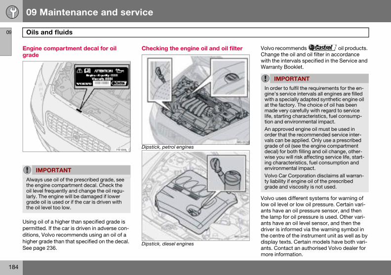
09 Maintenance and service
184
Oils 09
Enginegrade
Using opermitteditions, higher gSee pag
lvo recommends oil products. ange the oil and oil filter in accordance
th the intervals specified in the Service and arranty Booklet.
lvo uses different systems for warning of oil level or low oil pressure. Certain vari-
ts have an oil pressure sensor, and then e lamp for oil pressure is used. Other vari-ts have an oil level sensor, and then the iver is informed via the warning symbol in e centre of the instrument unit as well as by play texts. Certain models have both vari-ts. Contact an authorised Volvo dealer for ore information.
IM
Alwaysthe engoil levelarly. Tgrade the oil
IMPORTANT
n order to fulfil the requirements for the en-ine’s service intervals all engines are filled ith a specially adapted synthetic engine oil t the factory. The choice of oil has been ade very carefully with regard to service
ife, starting characteristics, fuel consump-ion and environmental impact. n approved engine oil must be used in rder that the recommended service inter-als can be applied. Only use a prescribed rade of oil (see the engine compartment ecal) for both filling and oil change, other-ise you will risk affecting service life, start-
ng characteristics, fuel consumption and nvironmental impact.olvo Car Corporation disclaims all warran-
y liability if engine oil of the prescribed rade and viscosity is not used.
and fluids
compartment decal for oil
il of a higher than specified grade is d. If the car is driven in adverse con-Volvo recommends using an oil of a rade than that specified on the decal. e 236.
Checking the engine oil and oil filter
Dipstick, petrol engines
Dipstick, diesel engines
VoChwiW
Volowanthandrthdisanm
PORTANT
use oil of the prescribed grade, see ine compartment decal. Check the l frequently and change the oil regu-he engine will be damaged if lower oil is used or if the car is driven with level too low.
IgwamltAovgdwieVtg
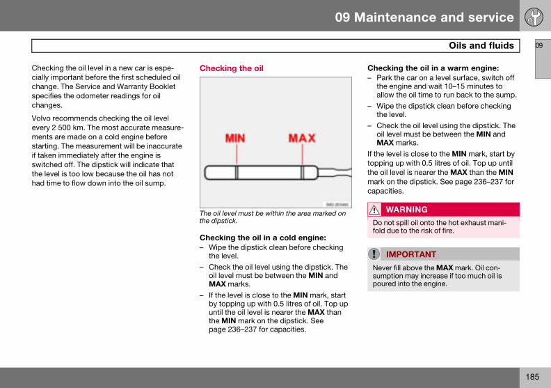
09 Maintenance and service
185
Oils and fluids 09
Checkincially imchange.specifiechanges
Volvo reevery 2 ments astarting.if taken switchethe levehad time
Checking the oil in a warm engine:– Park the car on a level surface, switch off
the engine and wait 10–15 minutes to allow the oil time to run back to the sump.
– Wipe the dipstick clean before checking the level.
– Check the oil level using the dipstick. The oil level must be between the MIN and MAX marks.
If the level is close to the MIN mark, start by topping up with 0.5 litres of oil. Top up until the oil level is nearer the MAX than the MIN mark on the dipstick. See page 236–237 for capacities.
WARNING
Do not spill oil onto the hot exhaust mani-fold due to the risk of fire.
IMPORTANT
Never fill above the MAX mark. Oil con-sumption may increase if too much oil is poured into the engine.
g the oil level in a new car is espe-portant before the first scheduled oil The Service and Warranty Booklet s the odometer readings for oil .
commends checking the oil level 500 km. The most accurate measure-re made on a cold engine before The measurement will be inaccurate immediately after the engine is d off. The dipstick will indicate that l is too low because the oil has not to flow down into the oil sump.
Checking the oil
The oil level must be within the area marked on the dipstick.
Checking the oil in a cold engine:– Wipe the dipstick clean before checking
the level.– Check the oil level using the dipstick. The
oil level must be between the MIN and MAX marks.
– If the level is close to the MIN mark, start by topping up with 0.5 litres of oil. Top up until the oil level is nearer the MAX than the MIN mark on the dipstick. See page 236–237 for capacities.
09 Maintenance and service
186
Oils 09
Washe
Location
The winshare a
See cap
1. Fillersel.
2. Fille
Checking and topping up the coolant
When topping up the coolant, follow the in-structions on the packaging. It is important that the mixture of coolant concentrate and water is correct for the prevailing weather conditions. Never top up with water only. The risk of freezing increases with both too little and too much coolant concentrate.
See capacities on page 241.1 Depend
IMPORTANT
Always use coolant with anti-corrosion agent as recommended by Volvo. New cars are filled with coolant that can withstand temperatures down to approximately –35 �C.
and fluids
r fluid, topping up
of washer fluid reservoir1.
dscreen and headlamp washers common reservoir.
acities on page 241.
cap on 4-cylinder engines and die-
r cap on 5-cylinder engines.
Add washer antifreeze during the winter so that the fluid does not freeze in the pump, reservoir and hoses.
ent on engine variant.
NOTE
Mix the washer antifreeze and water before filling the reservoir.
09 Maintenance and service
187
Oils and fluids 09
Check The leveMAX masystem temperadamagethe coolmark.
braking, such as driving in mountains or trop-ical climates with high humidity.
W
The corequireoperatsion taoverpr
NO
The enfilled ccan oc(cracks
WARNING
If the brake fluid is under the MIN level in the brake fluid reservoir, do not drive further before topping up the brake fluid.The reason for the loss of brake fluid must be investigated.
the coolant regularlyl should lie between the MIN and rks on the expansion tank. If the
is not filled sufficiently, high local tures could occur, causing a risk of (cracks) in the cylinder head. Top up ant when the level falls to the MIN
Checking and topping up the brake and clutch fluid
The brake and clutch fluid have a common reservoir1. The fluid level must be between the MIN and MAX marks. Check the level regularly. Change the brake fluid every other year or at every other regular service.
See the capacities and recommended fluid grade on page 237.
The fluid should be changed annually on cars driven in conditions requiring hard, frequent
ARNING
olant may be very hot. If the coolant s topping up when the engine is at ing temperature, unscrew the expan-nk cap slowly to gently release the essure.
TE
gine must only be run with a well-ooling system. High temperatures cur, causing a risk of damage ) to the cylinder head.
1 Location dependent on whether car is left or right-hand drive.
09 Maintenance and service
188
Oils 09
Checkisteerin
The fluidpacitiespage 23
If a faultsystem must beever thenormal athe whe
NO
Check
and fluids
ng and topping up the power g fluid
does not require changing. For ca- and recommended fluid grade, see 7.
should arise in the power steering or if the car is without power and towed, it can still be steered. How- steering will be much heavier than nd it will require more effort to turn
el.
TE
the level frequently.
09 Maintenance and service
189
Wiper blades 09
Chang
– Turn – Press
bladeparal
– Slide"click
– Chec– Fold
Changing the rear window wiper blade
– Fold out the wiper arm.– Detach the wiper blade by pulling it to-
wards the rear window.– Press home the new wiper blade. Check
that it is securely fitted.– Lower the wiper arm.
NO
The wiblade oblade o
ing the wiper blades
up the wiper arm. the button located on the wiper mounting and pull straight out (1), lel with the wiper arm. in (2) the new wiper blade until a " is heard.k (3) that the blade is firmly installed.down the wiper arm.
TE
per blades are different lengths. The n the driver’s side is longer than the n the passenger side.
09 Maintenance and service
190
Batte09
Battery
There mThey are
The servinfluencstarts, dditions a
IM
Alwaystery wa
NO
An expenvironcontain
WARNING
Batteries can generate oxyhydrogen gas, which is highly explosive. A spark, which can be generated if you connect the jump leads incorrectly, is sufficient to make the battery explode. The battery also contains sulphuric acid, which can cause serious burns. If the acid comes into contact with eyes, skin or clothing, flush with large quan-tities of water. If acid splashes into the eyes, seek medical advice immediately.
NOTE
The life of the battery is shortened if it be-comes discharged repeatedly
ry
care
ay be two different types of battery. fully interchangeable with each other.
ice life and function of the battery is ed by factors such as the number of ischarging, driving style, driving con-nd climatic conditions.
For the battery to function satisfactorily:
• Regularly check that the electrolyte level is correct (A) and never fill above the level mark.
• Check all cells. Use a screwdriver to re-move the cell caps (or the cover).
• If necessary, top up with distilled water to the battery’s maximum mark.
• Fit the cell caps (or the cover) firmly.
PORTANT
use distilled or deionised water (bat-ter).
TE
ended battery must be recycled in an mentally responsible manner as it s lead.
09 Maintenance and service
191
Battery 09
Symbo Changing the battery
Removing the battery– Switch off the ignition and remove the key.– Wait at least 5 minutes before touching
any electrical terminals. This allows time for the information in the car’s electrical system to be stored in the various control modules.
– Remove the cover.– Disconnect the negative battery lead.– Disconnect the positive battery lead.– Undo the front wall of the battery box
using a screwdriver.– Release the clamp securing the battery.– Remove the battery.
Fitting the battery– Fit the battery into position.– Fit the clamp securing the battery.– Reinstall the front wall of the battery box.– Connect the positive lead.– Connect the negative lead.– Refit the cover over the battery.
ls on the battery Use protective goggles
Further information in the Owner’s Manual.
Store the battery out of the reach of children.
The battery contains corro-sive acid.
Avoid sparks and naked flames.
Risk of explosion.
09 Maintenance and service
192
Repl09
Genera
All bulb
The follosource lble for c
• Gene• Read• Indic
ing• High-• Bi-Xe
– Unplug the connector by pressing down the clip with a thumb (3) while moving out the connector (4) with the other hand.
– Lift out the lamp housing and place it on a soft surface to avoid scratching the lens.
Fitting the lamp housing:– Plug in the connector and refit the lamp
housing and locking pin. Check that the pin is correctly inserted.
– Check the lighting.The lamp housing must be plugged in and secured in place before the lighting is turned on or the ignition key inserted into the ignition switch.
W
On carlamp reauthormust bthe hig
IM
Never gers. Gvaporising the
acing bulbs
l
specifications are given on page 247.
wing list contains bulbs and point-amps that are specialised or unsuita-hanging except at a workshop:
ral interior lighting in the roofing lamps and glovebox lightingator, door mirror and approach light-
level brake lightnon headlamp
Changing front bulbs
All front bulbs (except for fog lamps) are changed by first removing the lamp housing from the engine compartment.
Removing the lamp housing:– Remove the ignition key and turn the light
switch to position 0.– Withdraw the lamp housing’s locking
pin (1).– Pull the lamp housing to the side and then
forward (2) .
ARNING
s with Bi-Xenon headlamps, Xenon placement must be carried out by an
ised Volvo workshop. The headlamps e handled with extreme care due to h-voltage unit in the Xenon lamp.
PORTANT
touch the bulbs’ glass with your fin-rease and oils from your fingers are ed by the heat, coating and damag- reflector.
IMPORTANT
Do not pull the electrical cable, only the connector
09 Maintenance and service
193
Replacing bulbs 09
Dipped
Remov– Remo– Bend
cover– Unplu– Relea
bulb.then
– Pull o– Refit
Main beam
– Remove the entire lamp housing.– Left-hand headlamp:
Turn the bulb holder anticlockwise. Right-hand headlamp: Turn the bulb holder clockwise.
– Withdraw the bulb holder and change the bulb.
– Refit the bulb holder. It can only be fitted in one way.
– Refit the lamp housing.
beam
ing the cover and bulb:ve the entire lamp housing.
aside the catches and remove the .g the connector from the bulb.se the spring clip that secures the
First, press it to the left to release it, out and down.ut the bulb.the lamp housing.
Fitting a new bulb– Fit the new bulb. It can only be fitted in
one position.– Press the spring clip up and then slightly
to the right so that it clicks into place.– Press the connector back on.– Refit the plastic cover.– Refit the lamp housing.
09 Maintenance and service
194
Repl09
Positio
– Pull oplierspullin
– Repla– Press
can o
Side marker lamps
– Twist the bulb holder anticlockwise and withdraw it. Replace the bulb.
– Refit the bulb holder. It can only be fitted in one way.
acing bulbs
n/parking lamps
ut the bulb holder with a pair of . Do not pull out the bulb holder by g the electrical cable.ce the bulb. the bulb holder back into place. It nly be fitted in one way.
Direction indicators
– Twist the bulb holder anticlockwise and remove it.
– To remove the bulb from the bulb holder, press the bulb in and turn it anticlockwise.
– Fit a new bulb and refit the bulb holder into the lamp housing.
09 Maintenance and service
195
Replacing bulbs 09
Fog lam
– Switckey to
– Remohous
– Remolamping.
– Unplu– Turn – Fit th– Plug – Secu
and p
– Press the bulb holder into place and refit the cover (A or B).
NOTE
If the error message BULB FAILURE/CHECK STOP LAMP remains after a faulty bulb has been replaced then consult an au-thorised Volvo workshop.
ps
h off all lights and turn the ignition position 0.ve the panel from around the lamp
ing.ve the two Torx screws securing the
housing and take out the lamp hous-
g the connector from the bulb.the bulb anticlockwise and pull it out.e new bulb and turn it clockwise.in the connector to the bulb.re the lamp housing with the screws ress the panel back into place.
Removing the bulb holder
– All bulbs in the rear lamp cluster can be changed from inside the cargo area.
– Switch off all lights and turn the ignition key to position 0.
– Remove the cover (A or B) in the left/right-hand panel to access the bulbs.
– These bulbs are located in separate bulb holders.
– Unplug the connector from the bulb hold-er.
– Squeeze together the catches and remove the bulb holder.
– Replace the bulb.– Plug in the connector.
09 Maintenance and service
196
Repl09
Locatiocluster
Bulb hol
1. Brak2. Posi3. Dire4. Rea5. Reve
Courtesy lighting
– There is courtesy lighting under the dash-board on the driver and passenger sides.
– Insert a screwdriver and gently turn so that the lens detaches.
– Remove the blown bulb.– Fit a new bulb.– Refit the lens.
acing bulbs
n of the bulbs in the rear light
der
e lighttion/parking lampsction indicatorsr fog lamp (one side)rsing lamp
Number plate lighting
– Switch off all lights and turn the ignition key to position 0.
– Remove the screws with a screwdriver.– Detach the lens carefully.– Replace the bulb.– Refit and screw in the lens.
09 Maintenance and service
197
Replacing bulbs 09
Courte
– Inserthe la
– Remo– Fit a n
Fitting the mirror glass:– First, press the three lugs at top edge of
mirror glass back into position.– Then press the three lower lugs back into
position.
sy lighting
t a screwdriver and gently turn so that mp housing comes loose.ve the blown bulb.ew bulb.
Vanity mirror lighting
Removing the mirror glass:– Insert a screwdriver underneath the lower
edge, in the centre. Carefully prise up the lug on the edge.
– Insert the screwdriver under the edge on both the left and right side (at the black rubber points) and carefully prise so that the lens releases at the lower edge.
– Carefully detach and lift aside the entire mirror glass and cover.
– Remove the blown bulb and replace it with a new one.
09 Maintenance and service
198
Fuse09
Genera
All electfused tofrom daloading.
The fusecar:
• Relayment
• Relayment
s
l
rical functions and components are protect the car’s electrical system mage by short circuiting and over-
s are in two different locations in the
/Fuse box in the engine compart-
/fuse box in the passenger compart-.
Changing If an electrical component or function does not work, it may be because the compo-nent’s fuse was temporarily overloaded and blew.
– Look in the fuse diagram to locate the fuse.
– Pull out the fuse and check from the side to see whether the curved wire has blown.
– If this is the case, replace it with a new fuse of the same colour and amperage.
Each fuse box has space for several spare fuses. If the same fuse blows repeatedly it means that there is a fault in the component. Contact an authorised Volvo workshop to have the system checked.
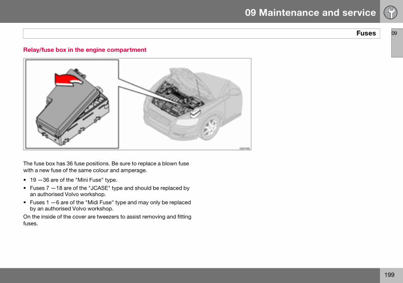
09
09 Maintenance and service
199
Fuses
Relay/f
The fusewith a n
• 19 —• Fuse
an au• Fuse
by anOn the ifuses.
use box in the engine compartment
box has 36 fuse positions. Be sure to replace a blown fuse ew fuse of the same colour and amperage.
36 are of the "Mini Fuse" type.s 7 —18 are of the "JCASE" type and should be replaced by thorised Volvo workshop.s 1 —6 are of the "Midi Fuse" type and may only be replaced authorised Volvo workshop.nside of the cover are tweezers to assist removing and fitting
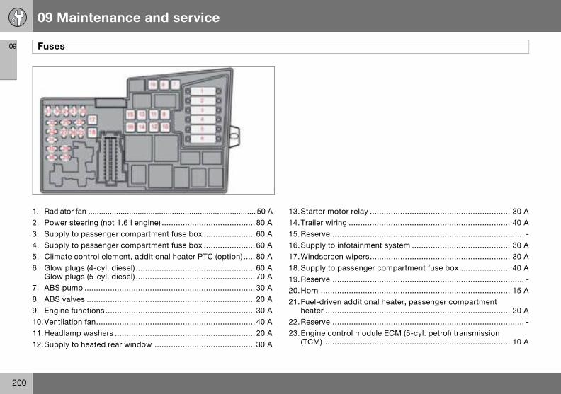
09
09 Maintenance and service
200
Fuse
1. Radi2. Pow3. Sup4. Sup5. Clim6. Glow
Glow7. ABS8. ABS9. Engi10.Vent11.Hea12.Sup
............................................................ 30 A
............................................................ 40 A
.................................................................. -ent system .......................................... 30 A............................................................ 30 Ar compartment fuse box ..................... 40 A
.................................................................. -
............................................................ 15 Aal heater, passenger compartment
............................................................ 20 A
.................................................................. -ule ECM (5-cyl. petrol) transmission ............................................................ 10 A
s
ator fan .............................................................................. 50 Aer steering (not 1.6 l engine) ........................................ 80 Aply to passenger compartment fuse box ...................... 60 Aply to passenger compartment fuse box ...................... 60 Aate control element, additional heater PTC (option) ..... 80 A plugs (4-cyl. diesel) ................................................... 60 A plugs (5-cyl. diesel) ................................................... 70 A
pump ......................................................................... 30 A valves ........................................................................ 20 Ane functions ................................................................ 30 Ailation fan.................................................................... 40 Adlamp washers ............................................................ 20 Aply to heated rear window ........................................... 30 A
13.Starter motor relay14.Trailer wiring .........15.Reserve ................16.Supply to infotainm17.Windscreen wipers18.Supply to passenge19.Reserve ................20.Horn .....................21.Fuel-driven addition
heater ...................22.Reserve ................23.Engine control mod
(TCM)....................
09
09 Maintenance and service
201
Fuses
24.Hea(5-c
25.Rese26. Ignit27.A/C 28.Rese29.Fog 30.Eng31.Volta32. Injec
charturb
33.Lamengidies
34. Ignitfuel presglow
35.EngPTCengiinjecMAFturbpresEGR
36.Engaccedies
ted fuel filter, PTC element oil trap yl. diesel) ..................................................................... 20 Arve ...................................................................................-
ion switch ................................................................... 15 Acompressor ................................................................ 10 Arve ...................................................................................-lamp, front .................................................................. 15 Aine control module ECM (1.6 l petrol, 2.0 l diesel) ...........3 A
ge regulator, alternator 4-cyl. ..................................... 10 Ators (5-cyl. petrol), lambda-sond (4-cyl. petrol), ge air cooler (4-cyl. diesel), mass air flow sensor and o control (5-cyl. diesel) ................................................ 10 Abda-sond and vacuum pump (5-cyl. petrol), ne control module (5-cyl. diesel), el filter heater (4-cyl. diesel) ........................................ 20 Aion coils (petrol), injectors (1.6 l petrol), pump (4-cyl. diesel), sure switch, climate control (5-cyl.), plugs and EGR emission control (5-cyl. diesel) .......... 10 A
ine sensors for valves, relay coil, air conditioning element, oil trap (5-cyl. petrol), ne control module ECM (5-cyl. diesel), canister (petrol), tors (1.8/2.0 l petrol, mass air flow sensor (5-cyl. petrol, 4-cyl. diesel), o control (4-cyl. diesel), sure switch power steering (1.6 l petrol), emission control (4-cyl. diesel) ................................... 15 A
ine control module ECM (not 5-cyl. diesel), lerator pedal position sensor, lambda-sond (5-cyl.
el) ............................................................................... 10 A
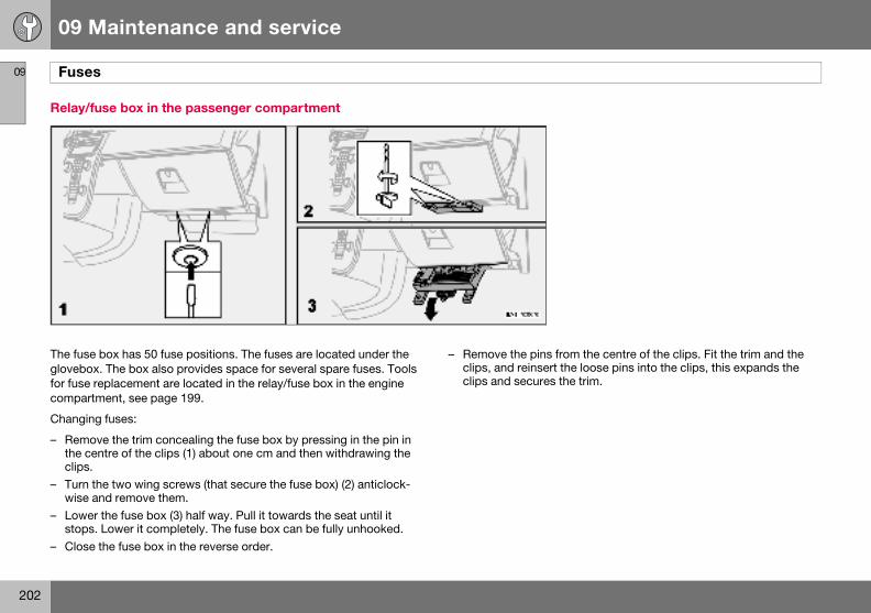
09
09 Maintenance and service
202
Fuse
Relay/f
The fuseglovebofor fuse compar
Changin
– Remothe cclips.
– Turn wise
– Lowestops
– Close
the centre of the clips. Fit the trim and the loose pins into the clips, this expands the trim.
s
use box in the passenger compartment
box has 50 fuse positions. The fuses are located under the x. The box also provides space for several spare fuses. Tools replacement are located in the relay/fuse box in the engine tment, see page 199.
g fuses:
ve the trim concealing the fuse box by pressing in the pin in entre of the clips (1) about one cm and then withdrawing the
the two wing screws (that secure the fuse box) (2) anticlock-and remove them.r the fuse box (3) half way. Pull it towards the seat until it . Lower it completely. The fuse box can be fully unhooked. the fuse box in the reverse order.
– Remove the pins fromclips, and reinsert theclips and secures the
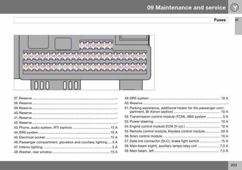
09
09 Maintenance and service
203
Fuses
37.Rese38.Rese39.Rese40.Rese41.Rese42.Rese43.Pho44.SRS45.Elec46.Pass47. Inter48.Was
............................................................ 10 A
.................................................................. - additional heater for the passenger com- (option) .............................................. 10 Aol module (TCM), ABS system ............... 5 A............................................................ 10 Aule ECM (5-cyl.) .................................. 10 Adule, Keyless control module ............... 20 Ale ......................................................... 10 A (DLC), brake light switch .................... 15 Auxiliary lamps relay coil ..................... 7,5 A
........................................................... 7,5 A
rve ...................................................................................-rve ...................................................................................-rve ...................................................................................-rve ...................................................................................-rve ...................................................................................-rve ...................................................................................-
ne, audio system, RTI (option) ..................................... 15 A system ....................................................................... 10 Atrical socket ................................................................ 15 Aenger compartment, glovebox and courtesy lighting ....5 Aior lighting ....................................................................5 Aher, rear window ......................................................... 15 A
49.SRS system ..........50.Reserve ................51.Parking assistance,
partment, Bi-Xenon52.Transmission contr53.Power steering ......54.Engine control mod55.Remote control mo56.Siren control modu57.Data link connector58.Main beam (right), a59.Main beam, left .....
09
09 Maintenance and service
204
Fuse
60.Seat61.Seat62.Sun63.Sup64.Aud65. Infot66. Infot67.Rese68.Crui69.Clim70.Rese71.Rese72.Rese73.Sun
rear74.Fuel75.Rese76.Rese77.Elec
(AEM78.Rese79.Reve80.Rese81.Sup82.Sup83.Sup
eat....................................................... 25 A........................................................... 25 Ago area lighting, vel display (1.8F) ................................... 5 A
s
heating (driver’s side)................................................. 15 A heating (passenger side) ............................................ 15 A
roof ............................................................................ 20 Aply to rear right door .................................................... 20 Aio system, RTI (option) ...................................................5 Aainment system ............................................................5 Aainment control module (ICM), climate control ............ 10 Arve ...................................................................................-
se control ......................................................................5 Aate control, rain sensor .................................................5 Arve ...................................................................................-rve ...................................................................................-rve ...................................................................................-
roof, overhead console (OHC) seatbelt reminder, autodim mirror .................................5 A pump relay ................................................................. 15 Arve ...................................................................................-rve ...................................................................................-
trical socket in cargo area, accessory electronic module ) ................................................................................ 15 Arve ...................................................................................-rsing lamp....................................................................5 Arve ...................................................................................-
ply to rear left door ...................................................... 20 Aply to front right door................................................... 25 Aply to front left door ..................................................... 25 A
84.Power passenger s85.Power driver’s seat86. Interior lighting, car
power seats, fuel le
09 Maintenance and service
205
09
206
General ...................................................................................................208Audio functions ......................................................................................209Radio functions ...................................................................................... 211CD functions .......................................................................................... 215Menu structure – audio system .............................................................. 217Phone functions (option) ........................................................................ 218Menu structure – phone .........................................................................225
10INFOTAINMENT SYSTEM

10 Infotainment system
208
Gene
10
Infotain
Infotainmaudio syment sythe contpad1, semessagfunction
Audio s
On/OffPOWERoff. If thenition ke
Dolby Surround Pro Logic II Dolby Surround Pro Logic II2 distributes the two stereo audio channels to left, centre, right and rear speakers. This provides a more realistic sound quality than that provided by standard two-channel stereo.
Dolby Surround Pro Logic II and the Dolby icon are trademarks of Dolby Laboratories Licensing Cor-
poration. The Dolby Surround Pro Logic II System is manufactured under license from Dolby Laboratories Licensing Corporation.
1 Option. 2 Premium Sound.
ral
ment system
ent is a system that integrates the stem and the phone1. The infotain-stem can be easily operated using rol panel or the steering wheel key-e page 57. The display (2) shows es and information on the current .
ystem
(1) switches the audio system on or audio system is active when the ig-y is turned to position 0 it continues
to be active until the key is removed from the ignition switch. The audio system is then started automatically the next time the key is turned to position I.
Menus Some infotainment system functions are controlled via a menu system. The current menu level is shown at the top right of the display. Menu options are shown in the mid-dle of the display.
• MENU (4) leads to the menu system.• Up/down with the navigation button (5)
moves between menu options.• ENTER (7) selects or activates/deacti-
vates a menu option.• EXIT (6) goes back one step in the menu
structure. A long press on EXIT will exit the menu system.
ShortcutsMenu options are numbered and can also be selected directly with the keypad (3).
EquipmentThe audio system can be equipped with dif-ferent options and different versions. There are three audio system versions: Perform-ance, High Performance and Premium Sound. FM and AM radio with RDS and CD player is however included in each version.
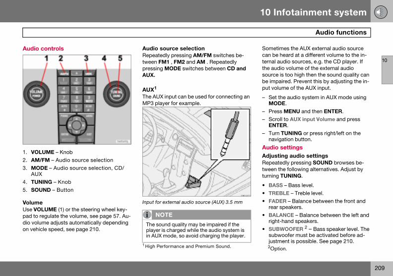
10 Infotainment system
209
Audio functions
10
Audio c
1. VOL2. AM/3. MOD
AUX4. TUN5. SOU
VolumeUse VOpad to rdio voluon vehic
Sometimes the AUX external audio source can be heard at a different volume to the in-ternal audio sources, e.g. the CD player. If the audio volume of the external audio source is too high then the sound quality can be impaired. Prevent this by adjusting the in-put volume of the AUX input.
– Set the audio system in AUX mode using MODE.
– Press MENU and then ENTER.– Scroll to AUX input Volume and press
ENTER.– Turn TUNING or press right/left on the
navigation button.
Audio settingsAdjusting audio settings Repeatedly pressing SOUND browses be-tween the following alternatives. Adjust by turning TUNING.
• BASS – Bass level.• TREBLE – Treble level.• FADER – Balance between the front and
rear speakers.• BALANCE – Balance between the left and
right-hand speakers.• SUBWOOFER 2 – Bass speaker level. The
subwoofer must be activated before ad-justment is possible. See page 210.2Option.
ontrols
UME – KnobFM – Audio source selectionE – Audio source selection, CD/
ING – KnobND – Button
LUME (1) or the steering wheel key-egulate the volume, see page 57. Au-me adjusts automatically depending le speed, see page 210.
Audio source selectionRepeatedly pressing AM/FM switches be-tween FM1 , FM2 and AM . Repeatedly pressing MODE switches between CD and AUX.
AUX1
The AUX input can be used for connecting an MP3 player for example.
Input for external audio source (AUX) 3.5 mm
1 High Performance and Premium Sound.
NOTE
The sound quality may be impaired if the player is charged while the audio system is in AUX mode, so avoid charging the player.
10 Infotainment system
210
Audi
10
• CENTchanactivaSee p
• SURRPro Ladjus
Activat– Press– Scrol
press– Scrol
Surrou
The DolDolby Pdifferent
• Pro L
• 3 cha• Off –
Activat– Press
car increases. There are three levels to choose from 4: Low , Medium and High.
Adjusting automatic volume control– Press MENU and then ENTER.– Scroll to Audio settings and
press ENTER.– Scroll to Automatic volume control and
press ENTER.– Scroll to Low, Medium or High and
press ENTER.
1 Premium 4 Not Performance Sound.
o functions
ER 1 – Centre speaker level. Three nel stereo or Pro Logic II must be ted before adjustment is possible. age 210.OUND 1 – Surround sound level.
ogic II must be activated before tment is possible. See page 210.
ing/deactivating the subwoofer MENU and then ENTER.l to Audio settings and ENTER.l to Subwoofer and press ENTER.
nd Surround settings1 govern the spa-tial perception of the sound. Set-tings and activating/deactivating are separate for each audio source.
by icon in the display indicates that ro Logic II is active. There are three settings for surround sound:
ogic II
nnel 2-channel stereo.
ing/deactivating surround sound MENU and then ENTER.
– Scroll to Audio settings and press ENTER.
– Scroll to Surround FM/AM/CD/AUX and press ENTER.
– Scroll to Pro Logic II 2, 3 channel or Off and press ENTER.
Equalizer front/rear The equalizer3 can be used to adjust different frequency bands separately.
Adjusting equalizer– Press MENU and then ENTER.– Scroll to Audio settings and
press ENTER.– Scroll to Equalizer front or Equalizer rear
and press ENTER.– The graphic on the display indicates the
audio level of the frequency in question.– Adjust the level with TUNING (4) or up/
down on the navigation button. Additional frequencies can be selected using the left/right navigation button.
– Use ENTER to save or EXIT to close.
Automatic volume control The auto volume control function allows the audio volume to increase as the speed of the
Sound.
2 Not available in AM and FM mode.3 Certain audio systems.
10 Infotainment system
211
Radio functions
10
Radio c
1. FM/2. Stat3. TUN4. SCA5. Nav6. EXIT7. AUT
Tuning
Automa– Selec– Give
navig
Automatic storage of stations AUTO (7) seeks out the ten strongest radio stations and stores them automatically in a separate memory. The function is especially useful in areas where one is unfamiliar with the radio stations and their frequencies.
Starting automatic storage of stations– Select wavelength using AM/FM (1).– Hold AUTO (7) depressed until Autostor-
ing... appears in the display.Once Autostoring... disappears from the dis-play, the stations are stored. The radio con-tinues in Auto mode and Auto appears in the display. The automatically stored stations can now be selected using the station preset buttons (2).
Cancelling automatic storage of sta-tions– Press EXIT (6).Selecting an auto-stored presetAllowing the radio to remain in Auto mode provides access to the autostored presets.
– Briefly press AUTO (7).Auto appears in the display.
– Press a preset button (2).The radio remains in Auto mode until it is ex-ited by a brief press on AUTO (7), EXIT (6) or AM/FM (1).
ontrols
AM – Wavelength selectionion presetsING – Knob for station searchesN – Scanningigation button – Tuning and menus – Cancel current functionO – Automatic storage of stations
tic tuningt wavelength using AM/FM (1).a brief press, left or right, on the ation button (5).
Manual tuning– Select wavelength using AM/FM (1).– Adjust the frequency by turning
TUNING (3).Tune into a station with a long press (left or right) on the navigation button or by using the steering wheel keypad:
– Hold the right or left side of the navigation button depressed until the desired fre-quency appears in the display.
As long as the frequency graphic appears in the display, searching can be resumed by briefly pressing the navigation button (left or right) (5)
Storing stations Ten station presets can be stored per wave-length. FM has two memories for presets: FM1 and FM2. Preset stations are selected using the preset buttons (2) or the steering wheel keypad.
Storing stations manually– Tune into a station.– Hold a station preset button depressed
until the message Station stored appears in the display.
10 Infotainment system
212
Radi
10
StoringmemorAn autothe FM o
– BrieflAuto ap
– Press– Press
will bthe mthe d
The radstation c
ScanniSCAN (4AM or Fis playedscannin
Activat– Selec– PressSCAN aSCAN o
StoringA desirewhile Sc
audio source and volume when the set pro-gramme type is no longer broadcast.
The programme functions alarm (ALARM), traffic information (TP), news (NEWS), and programme types (PTY) interrupt one anoth-er in order of priority, where alarm has the highest priority and programme types has the lowest. For further programme interrup-tion settings, see EON and REG on page 214. The programme functions are modified via the menu system, see page 208.
Returning to the interrupted audio sourcePress EXIT to return to the interrupted audio source.
Alarm This function is used to warn of serious acci-dents and catastrophes. The alarm cannot be temporarily interrupted or deactivated. The message ALARM! appears on the dis-play when an alarm message is transmitted.
Traffic information – TP This function allows traffic informa-tion sent within a set station’s RDS network to break through. TP indi-cates that the function is activated.
If the set station can send traffic information then appears on the display.
o functions
autostored presets in another ystored preset can be transferred to r AM memory.
y press AUTO (7).pears in the display.
a preset button. the button under which the station e stored and hold it depressed until essage Station stored appears in isplay.io exits Auto mode and the stored an be selected as a preset.
ng ) automatically searches for strong
M stations. When a station is found, it for approx. eight seconds before
g is resumed.
ing/deactivating Scant wavelength using AM/FM. SCAN to activate.ppears in the display. Cancel with r EXIT.
a stationd station can be stored as a preset an is active.
– Press a preset button and hold it de-pressed until the message Station stored appears in the display.
Scan is interrupted and the stored station can be selected as a preset.
RDS functionsRadio Data System – RDS links FM transmit-ters into a network. An FM transmitter in such a network sends information that gives an RDS radio the following functions:
• Automatically switches to a stronger transmitter if reception in the area is poor.
• Searches for programme form, such as traffic information or news.
• Receives text information on current radio programme.
Some radio stations do not use RDS or only some if its functionality.
Programme functions In FM mode, the radio can search for stations with certain programme types. If a desired programme type is found, the radio can switch stations, interrupting the audio source currently in use. For example, if the CD player is in use, it is paused. The interrupting trans-mission is played at a preset volume; see page 214. The radio returns to the previous
10 Infotainment system
213
Radio functions
10
Activat– Press– ScrolTP fromThe radtion fromall statio
– Selec– Press– Scrol
press– Scrol– ScrolEither TTP fromplay.
– PressActivatTP searwhile anbeing plsearcheent RDS
– Press– Scrol
press– Scrol
Serious classic. The PTY symbol indicates that the function is active. The function al-lows programme types transmitted within a set station’s RDS network to break through.
Activating/deactivating PTY– Select FM1 or FM2 with FM/AM.– Press MENU and then ENTER.– Scroll to PTY and press ENTER.– Scroll to Select PTY and press ENTER.A list of programme types appears: Current affairs , Information etc. The PTY function is activated by selecting programme types and deactivated by clearing all PTYs.
– Select the desired programme types or Clear all PTY
Search PTYThis function searches the entire wavelength for the selected programme type.
– Activate PTY.– Press MENU and then ENTER.– Scroll to PTY and press ENTER.– Scroll to Search PTY and press ENTER.If the radio finds any of the selected pro-gramme types, >| To seek appears in the display. Press the navigation button to the right to continue searching for another broadcast of the selected programme types.
ing/deactivating TP MENU and then ENTER.l to TP and press ENTER. current station/all stations
io can interrupt with traffic informa- only the set (current) station or from ns.
t an FM station. MENU and then ENTER.l to Advanced radio settings and ENTER.l to TP and press ENTER.l to TP Station and press ENTER.P from current station or all stations will appear in the dis-
ENTER.ing/deactivating TP searchch is useful during long journeys audio source other than the radio is ayed. The function automatically s for traffic information within differ- networks.
MENU and then ENTER.l to Advanced radio settings and ENTER.l to TP and press ENTER.
– Scroll to TP search and press ENTER.
News This function allows news broad-casts within a set station’s RDS network to break through. The mes-sage NEWS indicates that the func-
tion is active.
Activating/deactivating News– Press MENU and then ENTER.– Scroll to News and press ENTER.News from current station/all stationsThe radio can interrupt with news from only the set (current) station or from all stations.
– Select an FM station.– Press MENU and then ENTER.– Scroll to Advanced radio settings and
press ENTER.– Scroll to News station and press ENTER.Either News from current station or News from all stations will appear in the dis-play.
– Press ENTER.
Programme types – PTY The PTY function can be used to select different programme types, such as Pop music and
10 Infotainment system
214
Radi
10
DisplayThe procan be s
Activat– Press– Scrol– Scrol
Radio tSome Rprogrammation c
Activat– Press– Scrol
AutomThe AF transmitsometimFM wavthis occ to canc
• Distant 1 – interrupts if the station trans-mitter is far away, even if there is a lot of static.
• Off – no interruption for programmes from other transmitters.
Activating/deactivating EON– Press MENU and then ENTER.– Scroll to Advanced radio settings and
press ENTER.– Scroll to EON and press ENTER.– Scroll to Local , Distant or Off and press
ENTER.
Resetting RDS functions Resets all radio settings to the original facto-ry settings.
– Press MENU and then ENTER.– Scroll to Advanced radio settings and
press ENTER.– Scroll to Reset all and press ENTER.
Volume control, programme types The interrupting programme form is heard at the volume selected for such. If the volume level is adjusted during the programme inter-ruption, the new level is saved until the next programme interruption.
NO
Not all
1 Default/Factory setting.
o functions
of programme typegramme type of the current station hown in the display.
ing/deactivating display MENU and then ENTER.l to PTY and press ENTER.l to Show PTY and press ENTER.
ext DS stations transmit information on me content, artists, etc. This infor-an be shown in the display.
ing/deactivating radio text MENU and then ENTER.l to Radio text and press ENTER.
atic frequency update – AF function selects one of the strongest ters for a set station. The radio may es need to search through the entire
elength to find a strong transmitter. If urs, the radio mutes and PI seek Exit el appears on the display.
Activating/deactivating AF– Press MENU and then ENTER.– Scroll to Advanced radio settings and
press ENTER.– Scroll to AF and press ENTER.
Regional radio programmes – REG This function causes the radio to continue with a regional transmitter even if its signal strength is low. REG indicates that the function is
active. The regional function is normally de-activated.
Activating/deactivating REG– Press MENU and then ENTER.– Scroll to Advanced radio settings and
press ENTER.– Scroll to Regional and press ENTER.
Enhanced Other Networks – EON The EON function is particularly useful in ur-ban areas with many regional radio stations. It allows the distance between the car and the radio station transmitter determine when programme functions should interrupt the current audio source.
• Local – interrupts only if the radio station transmitter is close.
TE
radio stations support this function.
10 Infotainment system
215
CD functions
10
CD fun
1. Navitrack
2. CD c3. CD i4. CD i5. MOD
AUX6. TUN
StartinIf a mussystem ed automchange
PauseIf the volume is turned down completely, the CD player is stopped. The player is restarted when volume is increased.
Audio files1
The CD player also supports MP3 and WMA format audio files.
When a CD containing audio files is inserted into the player the disc’s directory structure is read in. It may take a while before playback starts depending on the quality of the disc.
Navigation and playbackIf a disc containing audio files is inside the CD player then ENTER leads to the disc’s di-rectory structure. The directory structure is navigated in the same way as the audio sys-tem’s menu structure. Audio files have the symbol and directories have the symbol . Start audio file playback with ENTER.
When the playback of a file is finished the playback of the other files in the same direc-tory continues. Directory change takes place automatically when all files in the current di-rectory have been played back.
1 High Pe
NOTE
Certain types of copy-protected audio files cannot be read by the player.
ction controls
gation button – Fast forward/rewind, selection and menushanger position selection1
nsertion/ejectnsertion/eject slotE – Audio source selection CD and
1
ING – Knob for track selection
g playback (CD player)ic CD is in the player when the audio is in CD mode then playback is start-
atically. Otherwise, load a disc and to CD mode by pressing MODE.
Starting playback (CD changer)If a CD position with a music CD is already selected when the audio system is activated then playback starts automatically. Other-wise change to CD changer mode using MODE and select a disc with the number buttons 1–6 or Up/Down on the navigation button.
Inserting a CD (CD changer)– Select an empty position with buttons 1–6
or Up/Down on the navigation button.An empty position is marked on the display. The text Insert disc shows that a new disc can be inserted. The CD changer can hold up to six CDs.
– Insert a CD in the slot of the CD changer.
CD ejectA CD will stay in the ejected position for ap-prox. 12 seconds. Following which it is re-in-serted into the player and playback contin-ues.
Eject individual discs by pressing the eject button (3).Eject all discs with one long press on the eject button. The entire magazine is emptied disc by disc. The message Eject all is shown in the display.
rformance and Premium Sound.

10 Infotainment system
216
CD fu
10
Press ledisplay iaudio filFast-wfiles Short prbutton aaudio filwind CDsteeringthis purpScan CThis funeach CDtivate. Intinue pldio file.
Random
This funder. Thescrolled
Differendependbeen se
• RANDone m
he function is deactivated when another CD selected.isc text title information is stored on a music CD it an be shown on the display1.
ctivating/deactivatingStart CD playback.Press MENU and then ENTER.Scroll to Disc text and press ENTER.
Dssing low quality CD discs could result in oor or non-existent sound.
NO
It is onCD tra
Only applies to CD changer.
IMPORTANT
Only use standard discs (12 cm in diame-ter). Do not use CDs with adhesive disc la-bels. The heat in the CD player may cause the label to come off, damaging the CD player.
nctions
ft/right on the navigation button if the s not wide enough to show the whole e name.ind/change CD tracks and audio
esses right/left on the navigation re used to scroll between CD tracks/es. Long presses are used to fast- tracks/audio files. TUNING (or the wheel keypad) can also be used for ose.
D ction plays the first ten seconds of track/audio file. Press SCAN to ac-terrupt with EXIT or SCAN to con-
ayback of the current CD track/au-
ction plays the tracks in random or- random CD tracks/audio files can be through in the normal way.
t messages appear on the display ing on which random function has lected.
OM means that the tracks from only usic CD are played
• RND ALL means that all tracks on all music CDs in the CD changer are played.
• RANDOM FOLDER means that the audio files in a directory on the current CD are played.
Activating/deactivating (CD player)– If a normal music CD is being played:– Press MENU and then ENTER.– Scroll to Random and press ENTER.If a disc with audio files is being played:
– Press MENU and then ENTER.– Scroll to Random and press ENTER.– Scroll to Folder or Disc and press ENTER.
Activating/deactivating (CD changer)If a normal music CD is being played:
– Press MENU and then ENTER.– Scroll to Random and press ENTER.– Scroll to Single disc or All discs and press
ENTER.The option All discs only applies to the mu-sic CDs in the changer.
If a CD with audio files is being played:
– Press MENU and then ENTER.– Scroll to Random and press ENTER.– Scroll to Single disc or Folder and press
ENTER.
TisDIfc
A–––
CUp
TE
ly possible to scroll between random cks on the current disc.
1
10 Infotainment system
217
Menu structure – audio system
10
FM me1. New
2. TP3. PTY
4. Rad5. Adva
6. Aud
AM me1. Aud
CD me1. Ran
2. New
3. TP4. Disc
5. Aud
CD cha1. Ran2. New
3. TP4. Disc
5. Aud
AUX m1. AUX1 Certain
nu s
io textnced radio settings
io settings1
nuio settings1
nudom
s
text
io settings1
nger menudom s
text
io settings1
enu volume
2. News
3. TP4. Audio settings1
audio systems.

10 Infotainment system
218
Phon
10
Phone sy
e functions (option)
stem components

10 Infotainment system
219
Phone functions (option)
10
Phone
1. Ante
2. SteeMost phcessed
3. MicrThe hanthe roof
4. CentAll phonbe regu
5. Priva
6. SIM
Genera• Alwa• If the
hand• Switc
ling th• Switc• Only
autho
SIM card
The phone can only be used with a valid SIM card (Subscriber Identity Module). The card is available from various network operators. Contact your network operator if you experi-ence difficulties with the SIM card.
Double SIM cardsMany network operators offer two SIM cards for the same phone number. The extra SIM card can be used in the car.
Inserting the SIM card– Switch off the phone and open the glove-
box.
system components
nna
ring wheel keypad (option)one system functions can be ac-via the keypad. See page 220.
ophoneds free microphone is integrated in console beside the rearview mirror.
re console control panele functions (except call volume) can lated via the control panel.
cy handset (option)
card reader
lys put traffic safety first. driver needs to use the privacy set, park the car in a safe place first.h off the phone system when refuel-e car.h off the system near blasting work.entrust phone system servicing to an rised Volvo workshop.
Emergency calls Emergency calls to alarm centres can be made without a SIM card as long as there is coverage by a GSM operator.
Making an emergency call– Activate the phone.– Ring the emergency number that applies
to your region (within EU: 112).– Press ENTER.
IDIS (Intelligent Driver Information System) The IDIS system allows incoming phone calls and text (SMS) messages to be delayed so that the driver can concentrate on driving. Incom-ing calls and text messages can be delayed five seconds before they are connected. Missed calls are shown on the display. IDIS can be deactivated using menu function 5.6.2. See page 226.
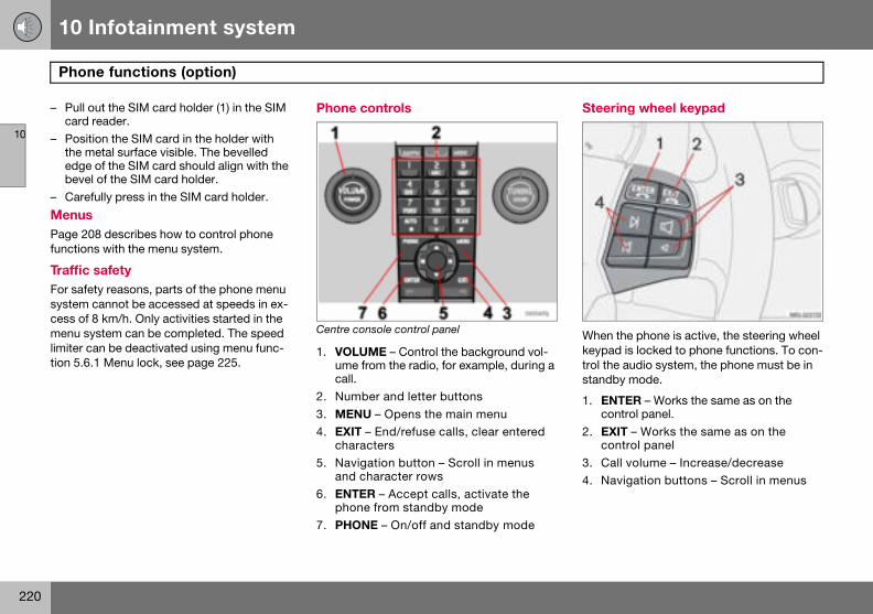
10 Infotainment system
220
Phon
10
– Pull ocard
– Positthe medgebeve
– Caref
MenusPage 20function
Traffic For safesystem cess of menu sylimiter ction 5.6.
Steering wheel keypad
When the phone is active, the steering wheel keypad is locked to phone functions. To con-trol the audio system, the phone must be in standby mode.
1. ENTER – Works the same as on the control panel.
2. EXIT – Works the same as on the control panel
3. Call volume – Increase/decrease4. Navigation buttons – Scroll in menus
e functions (option)
ut the SIM card holder (1) in the SIM reader.ion the SIM card in the holder with etal surface visible. The bevelled of the SIM card should align with the l of the SIM card holder.ully press in the SIM card holder.
8 describes how to control phone s with the menu system.
safetyty reasons, parts of the phone menu cannot be accessed at speeds in ex-8 km/h. Only activities started in the stem can be completed. The speed an be deactivated using menu func-1 Menu lock, see page 225.
Phone controls
Centre console control panel
1. VOLUME – Control the background vol-ume from the radio, for example, during a call.
2. Number and letter buttons3. MENU – Opens the main menu4. EXIT – End/refuse calls, clear entered
characters5. Navigation button – Scroll in menus
and character rows6. ENTER – Accept calls, activate the
phone from standby mode7. PHONE – On/off and standby mode
10 Infotainment system
221
Phone functions (option)
10
On/Off
A handsphone sthe ignitthe phonautomattime the
ActivatPhone swhen th
– Press– Enter
press
DeactivNo callsdeactiva
– Hold activa
StandbIn standuse whinot possmode.
PuttingThe phofore it ca
Call waitingA two-tone signal during a phone call indi-cates that there is another incoming call. An-swer? appears on the display. The call can be refused or taken in the normal manner. If the incoming call is taken, the previous call is put on hold.
Putting a call on hold/resuming a call– Press MENU.– Scroll to Hold or Hold off and press
ENTER.
Dialling a third party– Put the call on hold.– Dial the number of the third party.
Switching between calls– Press MENU.– Scroll to Swap and press ENTER.
Starting a conference callA conference call consists of at least three parties that can talk to one another. Once a conference call has been initiated, no more parties can be connected. All calls are ended when the conference call is ended.
– Start two phone calls– Press MENU.– Scroll to Join and press ENTER.
et appears in the display when the ystem is active or in standby mode. If ion key is turned to position 0 when e is in one of these mode, the phone ically resumes this mode the next key is turned to position I or II.
ing the phone systemystem functions can only be used e phone is in active mode.
PHONE. the PIN code (if necessary) and ENTER.
ating the phone system can be received when the phone is ted.
PHONE depressed until the phone is ted.
yby mode, the audio system can be in le calls are received. However, it is ible to make calls when in standby
the phone in standby mode ne must first be in active mode be-n be put in standby mode.
– Press PHONE or EXIT.Activating from standby mode– Press PHONE.
Making and receiving calls If the privacy handset is raised when a phone call is started, the sound will come from the handsfree system. For information on switch-ing between privacy handset and handsfree during a call, see page 223.
To call– Activate the phone system (if necessary).– Dial the number or use the phone book,
see page 223.– Press ENTER or lift the handset. Release
the handset by pressing it down.
Receiving a callFor Auto answer, see menu option 4.3, page 225.
– Press ENTER or lift the handset. Release the handset by pressing it down.
Ending a call– Press EXIT or hang up the handset.
Refusing a call– Press EXIT.
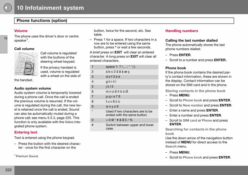
10 Infotainment system
222
Phon
10
VolumeThe phospeaker
Call vo
the hand
Audio sAudio syduring athe prevume is rel is retacan alsophone cfunctiongrated p
EnterinText is e
– Presster - o
Handling numbers
Calling the last number dialledThe phone automatically stores the last phone numbers dialled.
– Press ENTER.– Scroll to a number and press ENTER.
Phone bookIf the phone book contains the desired par-ty’s contact information, these are shown in the display. Contact information can be stored on the SIM card and in the phone.
Storing contacts in the phone book– Press MENU.– Scroll to Phone book and press ENTER.– Scroll to New number and press ENTER.– Enter a name and press ENTER.– Enter a number and press ENTER.– Scroll to SIM card or Phone and press
ENTER.Searching for contacts in the phone bookUse the down arrow of the navigation button instead of MENU for direct access to the Search menu.
– Press MENU.– Scroll to Phone book and press ENTER.
1 Premium
e functions (option)
ne uses the driver’s door or centre 1.
lume Call volume is regulated with the buttons of the steering wheel keypad.
If the privacy handset is used, volume is regulated with a wheel on the side of
set.
ystem volumestem volume is temporarily lowered phone call. Once the call is ended ious volume is resumed. If the vol-egulated during the call, the new lev-ined once the call is ended. Sound be automatically muted during a all; see menu 5.5.3, page 225. This is only available with the Volvo inte-hone system.
g text ntered using the phone keypad.
the button with the desired charac-nce for the first character on the
button, twice for the second, etc. See table.
– Press 1 for a space. If two characters in a row are to be entered using the same button, press * or wait a few seconds.
A brief press on EXIT will clear an entered character. A long press on EXIT will clear all entered characters.
Sound.
1 space 1- ? ! , . : " ' ( )2 a b c 2 ä å à æ ç3 d e f 3 è é4 g h i 4 ì5 j k l 56 m n o 6 ñ ö ò Ø7 p q r s 7 ß8 t u v 8 ü ù9 w x y z 9* Used if two characters are to be
ended with the same button.0 + 0 @ * # & $ £ / %# Switch between upper and lower
case.
10 Infotainment system
223
Phone functions (option)
10
– Scrol– Enter
press– ScrolCopyinand Ph– Press– Scrol– Scrol– Scrol
and pDeletin– Press– Scrol– Scrol– Enter
press– Scrol
ENTE– ScrolErase a– Press– Scrol– Scrol
pressIf requirset defa
Calling from the phone book – Press MENU.– Scroll to Phone book and press ENTER.All contacts in the phone book memory are displayed. The number of contacts displayed can be reduced by entering part of the con-tact’s name.
– Scroll to a contact and press ENTER.
Functions during a call Several functions are available during a call. Some functions can only be used when a call is on hold.
Press MENU to access the In-call menu and scroll to one of the following alternatives:
• Mute/Mute off – Mute mode.• Hold/Hold off – Put a call on hold or
resume a call.• Handsfree/Handset – Use handsfree or
the privacy handset.• Phone book – Access the phone book.• Join – Conference calling (available if
more than three parties are connected)
NOTE
Press ENTER to dial.
l to Search and press ENTER. the first few letters of the item and ENTER , or simply press ENTER.l to an item and press ENTER.g entries between the SIM card one book MENU.l to Phone book and press ENTER.l to Copy all and press ENTER.l to SIM to phone or Phone to SIM ress ENTER.g contacts from the phone book MENU.l to Phone book and press ENTER.l to Search and press ENTER. the first few letters of the item and ENTER , or simply press ENTER.l to the item to be erased and press R.
l to Erase and press ENTER.ll contacts MENU.l to Phone book and press ENTER.l to Erase SIM or Erase phone and ENTER.
ed, enter phone code. The factory-ult code is 1234.
Speed dial A keypad button (1-9) can be used as a speed dial number for a contact in the phone book.
– Press MENU.– Scroll to Phone book and press ENTER.– Scroll to One-key dial and press ENTER.– Scroll to Select numbers and
press ENTER.– Scroll to the digit of the keypad button for
the speed dial number and press ENTER.– Enter the first few letters of the item and
press ENTER , or simply press ENTER.– Scroll to an item and press ENTER.– Hold EXIT depressed to leave the menu
system.Calling using speed dial– Hold the desired keypad button for
approx. two seconds or briefly press the button and then ENTER.
To use the speed dial function One-key dial must be activated in the Phone book menu, see page 227.
NOTE
When the phone is switched on, it takes a while before speed dialling is available.
10 Infotainment system
224
Phon
10
• Swapble if
SMS –
Readin– Press– Scrol– Scrol– ScrolThe mesditional pressingleave th
Writing– Press– Scrol– Scrol– Enter– Scrol– Enter
IMEI nuTo blocknetworknumberis progrdisplay number
e functions (option)
– Switch between two calls (availa-up to three parties are connected).
Short Message Service
g SMS MENU.l to Messages and press ENTER.l to Read and press ENTER.l to a message and press ENTER.sage text appears in the display. Ad-
selections can be made by ENTER. Hold EXIT depressed to
e menu system.
and sending MENU.l to Messages and press ENTER.l to Write new and press ENTER. text and press ENTER.l to Send and press ENTER. a phone number and press ENTER.
mber the phone, you must provide your operator with the phone’s IMEI . This is a 15 digit serial number that ammed into the phone. Dial *#06# to this number. Make a note of this and keep it in a safe place.
Specifications
Output 2 WSIM card SmallMemory entries 2551
1The capacity of the SIM card’s memory varies depending on the subscription.
SMS (Short Message Service)
Yes
Data/Fax NoDualband (900/1800 MHz) Yes
10 Infotainment system
225
Menu structure – phone
10
Overvie
1. Call 1.1.1.2.1.3.1.4.
1.41.41.41.4
1.5.1.51.51.51.5
2. Mes2.1.2.2.2.3.
2.32.32.3
5. Tel. settings5.1. Network
5.1.1. Automatic5.1.2. Manual select
5.2. Language5.2.1. English UK5.2.2. English US5.2.3. Español5.2.4. Français CAN5.2.5. Français FR5.2.6. Italiano 5.2.7. Nederlands5.2.8. Português BR5.2.9. Português P5.2.10. Suomi5.2.11. Svenska5.2.12. Dansk5.2.13. Deutsch
5.3. SIM security5.3.1. On5.3.2. Off5.3.3. Automatic
5.4. Edit codes5.4.1. PIN code5.4.2. Phone code
5.5. Sound5.5.1. Ring volume5.5.2. Ring signal5.5.3. Mute radio5.5.4. Msg. beep
w
registerMissed callsReceived callsDialled no.Erase list
.1. All calls
.2. Missed calls
.3. Received calls
.4. Dialled no.Call duration
.1. Last call
.2. Number of calls
.3. Total time
.4. Reset time
sagesReadWriteMessage sett
.1. SMSC number
.2. Validity time
.3. Message type
3. Phone book3.1. New number3.2. Search3.3. Copy all
3.3.1. SIM to phone3.3.2. Phone to SIM
3.4. One-key dial3.4.1. Active3.4.2. Select number
3.5. Erase SIM3.6. Erase phone3.7. Memory status
4. Call options4.1. Send my no.4.2. Call waiting4.3. Auto answer4.4. Automatic redial4.5. Diversion
4.5.1. All calls4.5.2. When engag.4.5.3. Not answered4.5.4. Not reachable4.5.5. Fax calls4.5.6. Data calls4.5.7. Cancel all diverts
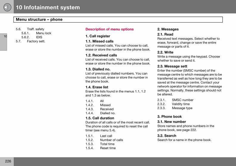
10 Infotainment system
226
Menu
10
5.6.5.65.6
5.7.
2. Messages2.1. ReadReceived text messages. Select whether to erase, forward, change or save the entire message or parts of it.
2.2. WriteWrite a message using the keypad. Choose whether to save or send it.
2.3. Message settEnter the number (SMSC number) of the message centre to which messages are to be transferred as well as how long they are to be saved at the message centre. Contact your network operator for information on message settings. Normally, these settings should not be altered.
2.3.1. SMSC number2.3.2. Validity time2.3.3. Message type
3. Phone book3.1. New numberStore names and phone numbers in the phone book, see page 222.
3.2. SearchSearch for a name in the phone book.
structure – phone
Traff. safety.1. Menu lock.2. IDISFactory sett.
Description of menu options
1. Call register1.1. Missed callsList of missed calls. You can choose to call, erase or store the number in the phone book.
1.2. Received callsList of received calls. You can choose to call, erase or store the number in the phone book.
1.3. Dialled no.List of previously dialled numbers. You can choose to call, erase or store the number in the phone book.
1.4. Erase listErase the lists found in the menus 1.1, 1.2 and 1.3 as below.
1.4.1. All1.4.2. Missed1.4.3. Received1.4.4. Dialled no.
1.5. Call durationDuration of all calls or of the most recent call. The phone code is required to reset the call timer (see menu 5.4).
1.5.1. Last call1.5.2. Number of calls1.5.3. Total time1.5.4. Reset time
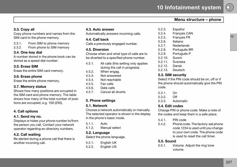
10 Infotainment system
227
Menu structure – phone
10
3.3. CoCopy phSIM car
3.3.1.3.3.2.
3.4. OnA numbstored a
3.5. EraErase th
3.6. EraErase th
3.7. MeShows hthe SIMshows htions are
4. Call 4.1. SeDisplaysthe persoperato
4.2. CaBe alertanother
5.2.3. Español5.2.4. Français CAN5.2.5. Français FR5.2.6. Italiano 5.2.7. Nederlands5.2.8. Português BR5.2.9. Português P5.2.10. Suomi5.2.11. Svenska5.2.12. Dansk5.2.13. Deutsch
5.3. SIM securitySelect if the PIN code should be on, off or if the phone should automatically give the PIN code.
5.3.1. On5.3.2. Off5.3.3. Automatic
5.4. Edit codesChange PIN or phone code. Make a note of the codes and keep them in a safe place.
5.4.1. PIN code5.4.2. Phone code. The factory-set phone
code 1234 is used until you change to your own code. The phone code is used to reset the call timer.
5.5. Sound5.5.1. Volume. Adjust the ring tone
volume.
py allone numbers and names from the
d to the phone memory.
From SIM to phone memoryFrom phone to SIM memory
e-key dialer stored in the phone book can be s a speed dial number.
se SIMe entire SIM card memory.
se phonee entire phone memory.
mory statusow many positions are occupied in
card and phone memory. The table ow many of the total number of posi- occupied, e.g. 100 (250).
optionsnd my no. or hides your phone number to/from on you call. Contact your network r regarding ex-directory numbers.
ll waitinged during a phone call that there is incoming call.
4.3. Auto answerAutomatically answers incoming calls.
4.4. Call backCalls a previously engaged number.
4.5. DiversionChoose when and what type of calls are to be diverted to a specified phone number.
4.5.1. All calls (this setting only applies during the call in progress).
4.5.2. When engag.4.5.3. Not answered4.5.4. Not reachable4.5.5. Fax calls4.5.6. Data calls4.5.7. Cancel all diverts
5. Phone settings5.1. NetworkChoose a network automatically or manually. The selected operator is shown in the display in the phone’s basic mode.
5.1.1. Auto5.1.2. Manual select
5.2. LanguageSelect the phone language.
5.2.1. English UK5.2.2. English US
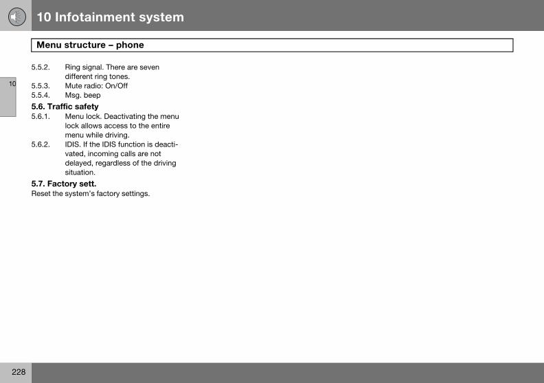
10 Infotainment system
228
Menu
10
5.5.2.
5.5.3.5.5.4.
5.6. Tra5.6.1.
5.6.2.
5.7. FaReset th
structure – phone
Ring signal. There are seven different ring tones.Mute radio: On/OffMsg. beep
ffic safetyMenu lock. Deactivating the menu lock allows access to the entire menu while driving.IDIS. If the IDIS function is deacti-vated, incoming calls are not delayed, regardless of the driving situation.
ctory sett.e system’s factory settings.
10 Infotainment system
229
10
230
Type designation .................................................................................... 232Dimensions and weights ........................................................................ 233Engine specifications ............................................................................. 234Engine oil................................................................................................ 236Fluids and lubricants.............................................................................. 240Fuel......................................................................................................... 242Catalytic converter ................................................................................. 245Electrical system .................................................................................... 246
11SPECIFICATIONS
11 Specifications
232
Type
11
wing the car’s type designation, vehicle tification and engine numbers can facili-all contact with a Volvo dealer regarding ar and when ordering spare parts and ssories.
ype designation, vehicle identification umber, maximum permissible weights, odes for colour and upholstery and type pproval number.ecal for parking heater.ngine type designation, component nd serial number.ecal for engine oil.earbox type designation and serial umber:a) manual gearbox
b), (c) automatic gearbox
IN number (type and model year des-gnation plus chassis number).
designation
Knoidentate the cacce
1. Tnca
2. D3. E
a4. D5. G
n(
(
6. Vi

11 Specifications
233
Dimensions and weights
11
Dimens
Length:
Width: 1
Wheelba
Front tra
Rear tra
WeightKerb we90 % fugers andcarriers,(when aes the pthe kerbto driverweight.
Maximum load: See registration document.
Max. roof load : 75 kg
Trailer with brakes:
Trailer without brakes
W
The capendinthe loa
Maximum trailer weight kg
Maximum towball load
kg
1.6 1200 751.6D 13001.8 13002.0 1350others 1500
Maximum trailer weight kg
Maximum towball load
kg
700 50
ions
451 cm
77 cm
se: 264 cm
ck: 154 – 155 cm
ck: 153 – 154 cm
s ight includes the driver, the fuel tank ll and all fluids. The weight of passen- accessories,such as a towbar, load space box etc. and towball load trailer is hitched, see table),influenc-ayload and must not be included in weight. Permitted weight (in addition ) = Gross vehicle weight – Kerb
See decal location on page 232.
1. Max. total weight2. Max. train weight (car+trailer)3. Max. front axle load 4. Max. rear axle load
Only for China
1. Max. total weight2. Maximum trailer weight
ARNING
r’s driving characteristics change de-g on how heavily it is loaded and how d is distributed.
11 Specifications
234
Engin
11
Engine trial numpage 23
2.4i T5
Engine B5244S4 B5254T3Output 125/6000 162/5000(hp/rpm 170/6000 220/5000Torque 230/4400 320/1500–4800No. of c 5 5Bore (m 83 83Stroke 90 93.2Swept 2.44 2.52Compr 10.3:1 9.0:1
e specifications
ype designation, component and se-ber can be read on the engine, see 2.
1.6 1.8 2.0 2.4
designation B4164S3 B4184S11 B4204S3 B5244S5 (kW/rpm) 74/6000 92/6000 107/6000 103/5000) 100/6000 125/6000 145/6000 140/5000
(Nm/rpm) 150/4000 165/4000 185/4500 220/4000ylinders 4 4 4 5m) 79 83 87 83
(mm) 81.4 83.1 83 90volume (litres) 1.60 1.80 1.99 2.44ession ratio 11.0:1 10.8:1 10.8:1 10.3:1
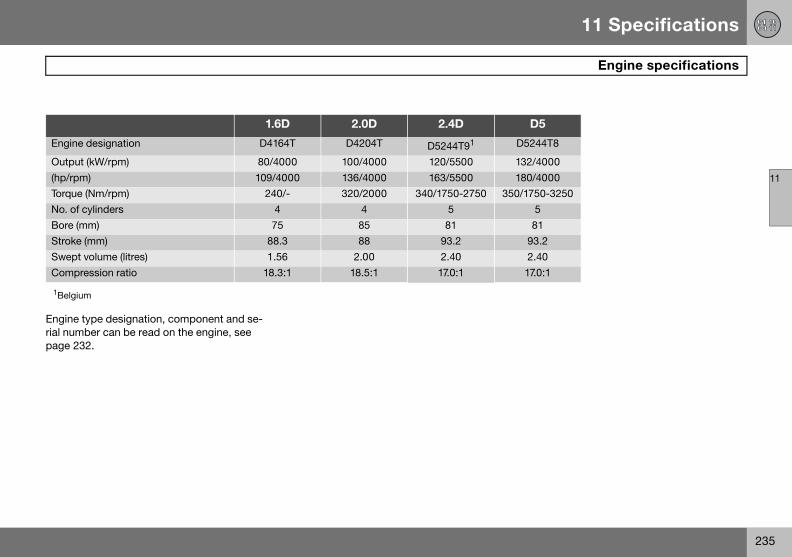
11 Specifications
235
Engine specifications
11
Engine trial numpage 23
D5
Engine 5244T8
Output 2/4000(hp/rpm 0/4000Torque 1750-3250No. of c 5Bore (m 81Stroke 93.2Swept 2.40Compr 17.0:1
1Belgiu
ype designation, component and se-ber can be read on the engine, see 2.
1.6D 2.0D 2.4D
designation D4164T D4204T D5244T91 D
(kW/rpm) 80/4000 100/4000 120/5500 13) 109/4000 136/4000 163/5500 18
(Nm/rpm) 240/- 320/2000 340/1750-2750 350/ylinders 4 4 5m) 75 85 81
(mm) 88.3 88 93.2volume (litres) 1.56 2.00 2.40ession ratio 18.3:1 18.5:1 17.0:1
m
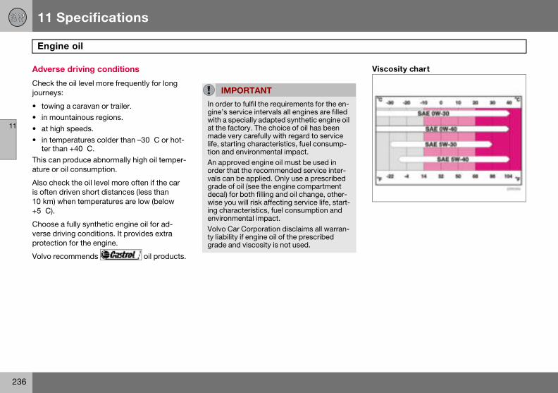
11 Specifications
236
Engin
11
Advers
Check tjourneys
• towin• in mo• at hig• in tem
ter thThis canature or
Also cheis often 10 km) w+5 �C).
Chooseverse drprotecti
Volvo re
Viscosity chart
e oil
e driving conditions
he oil level more frequently for long :
g a caravan or trailer.untainous regions.h speeds.peratures colder than –30 �C or hot-
an +40 �C. produce abnormally high oil temper-
oil consumption.
ck the oil level more often if the car driven short distances (less than hen temperatures are low (below
a fully synthetic engine oil for ad-iving conditions. It provides extra on for the engine.
commends oil products.
IMPORTANT
In order to fulfil the requirements for the en-gine’s service intervals all engines are filled with a specially adapted synthetic engine oil at the factory. The choice of oil has been made very carefully with regard to service life, starting characteristics, fuel consump-tion and environmental impact. An approved engine oil must be used in order that the recommended service inter-vals can be applied. Only use a prescribed grade of oil (see the engine compartment decal) for both filling and oil change, other-wise you will risk affecting service life, start-ing characteristics, fuel consumption and environmental impact.Volvo Car Corporation disclaims all warran-ty liability if engine oil of the prescribed grade and viscosity is not used.
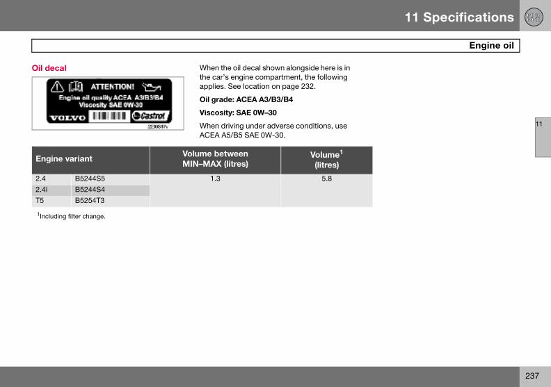
11 Specifications
237
Engine oil
11
Oil dec
Engin
2.42.4iT5
1Includ
al When the oil decal shown alongside here is in the car’s engine compartment, the following applies. See location on page 232.
Oil grade: ACEA A3/B3/B4
Viscosity: SAE 0W–30
When driving under adverse conditions, use ACEA A5/B5 SAE 0W-30.
e variantVolume betweenMIN–MAX (litres)
Volume1
(litres)
B5244S5 1.3 5.8B5244S4B5254T3
ing filter change.
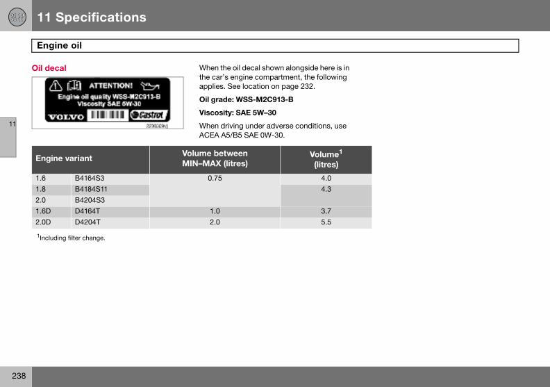
11 Specifications
238
Engin
11
Oil dec
Engin
1.61.82.01.6D2.0D
1Includ
e oil
al When the oil decal shown alongside here is in the car’s engine compartment, the following applies. See location on page 232.
Oil grade: WSS-M2C913-B
Viscosity: SAE 5W–30
When driving under adverse conditions, use ACEA A5/B5 SAE 0W-30.
e variantVolume betweenMIN–MAX (litres)
Volume1
(litres)
B4164S3 0.75 4.0B4184S11 4.3B4204S3D4164T 1.0 3.7D4204T 2.0 5.5
ing filter change.
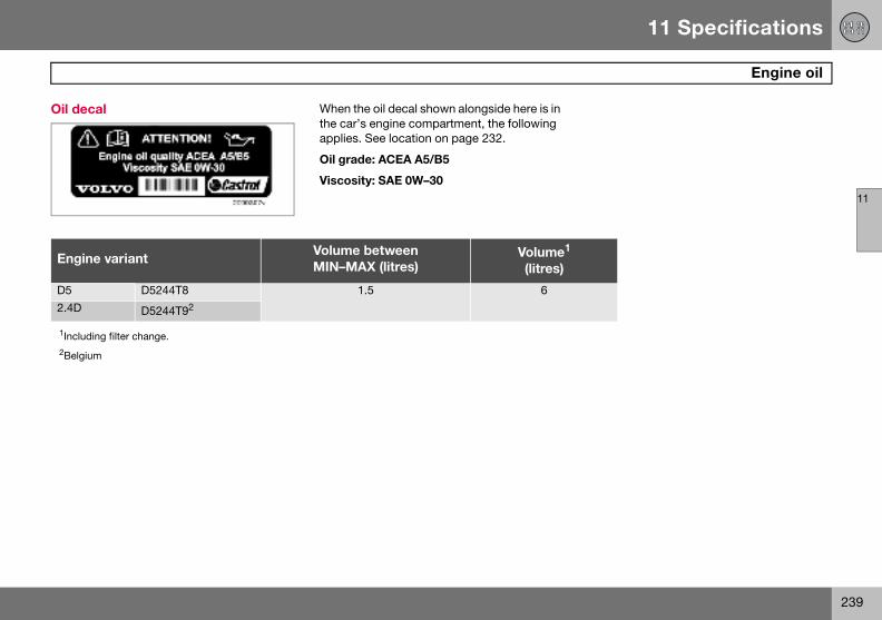
11 Specifications
239
Engine oil
11
Oil dec
Engin
D52.4D
1Includ2Belgiu
al When the oil decal shown alongside here is in the car’s engine compartment, the following applies. See location on page 232.
Oil grade: ACEA A5/B5
Viscosity: SAE 0W–30
e variantVolume betweenMIN–MAX (litres)
Volume1
(litres)
D5244T8 1.5 6
D5244T92
ing filter change.
m
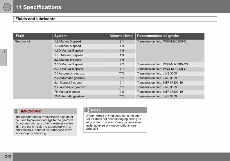
11 Specifications
240
Fluid
11
Fluid ended oil grade:
Gearbo n fluid: WSD-M2C200-C
n fluid: WSS-M2C200-C3n fluid: WSD-M2C200-Cn fluid: JWS 3309n fluid: JWS 3309n fluid: MTF 97309-10n fluid: JWS 3309n fluid: MTF 97309-10n fluid: JWS 3309
IM
The recbe useDo notid. If thdiffereworksh
s and lubricants
System Volume (litres) Recomm
x oil 1.6 Manual 5 speed 2.1 Transmissio1.8 Manual 5 speed 1.91.6D Manual 5 speed 1.91.8F Manual 5-speed 1.92.0 Manual 5-speed 1.92.0D Manual 5 speed 2.2 Transmissio2.0D Manual 6 speed 1.7 TransmissioD5 Automatic gearbox 7.75 Transmissio2.4 Automatic gearbox 7.75 Transmissio2.4i Manual 5 speed 2.1 Transmissio2.4i Automatic gearbox 7.75 TransmissioT5 Manual 6 speed 2.0 TransmissioT5 Automatic gearbox 7.75 Transmissio
PORTANT
ommended transmission fluid must d to prevent damage to the gearbox. mix with any other transmission flu-e transmission is topped up with a nt fluid, contact an authorised Volvo op for servicing.
NOTE
Under normal driving conditions the gear-box oil does not need changing during its service life. However, it may be necessary under adverse driving conditions, see page 236
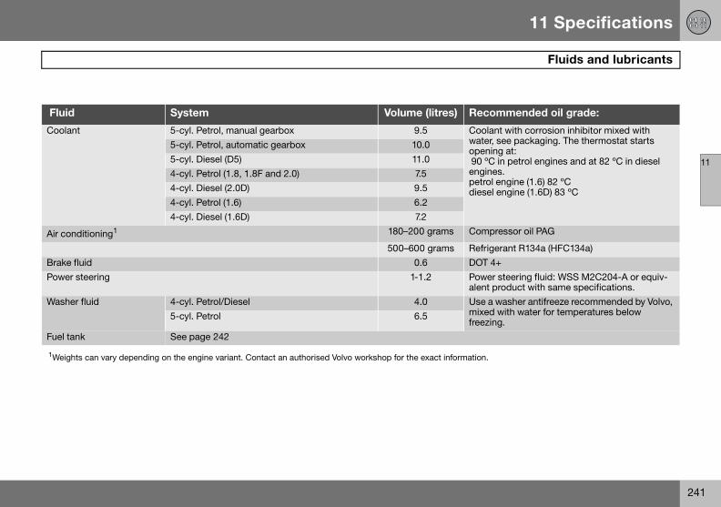
11 Specifications
241
Fluids and lubricants
11
Fluid ecommended oil grade:
Coolan oolant with corrosion inhibitor mixed with ater, see packaging. The thermostat starts ening at:
0 ºC in petrol engines and at 82 ºC in diesel gines. trol engine (1.6) 82 ºC
esel engine (1.6D) 83 ºC
Air con ompressor oil PAG
efrigerant R134a (HFC134a)Brake f OT 4+Power ower steering fluid: WSS M2C204-A or equiv-
ent product with same specifications.Washe se a washer antifreeze recommended by Volvo,
ixed with water for temperatures below eezing.
Fuel tan
1Weigh ion.
System Volume (litres) R
t 5-cyl. Petrol, manual gearbox 9.5 Cwop 9enpedi
5-cyl. Petrol, automatic gearbox 10.05-cyl. Diesel (D5) 11.04-cyl. Petrol (1.8, 1.8F and 2.0) 7.54-cyl. Diesel (2.0D) 9.54-cyl. Petrol (1.6) 6.24-cyl. Diesel (1.6D) 7.2
ditioning1 180–200 grams C
500–600 grams Rluid 0.6 Dsteering 1-1.2 P
alr fluid 4-cyl. Petrol/Diesel 4.0 U
mfr
5-cyl. Petrol 6.5
k See page 242
ts can vary depending on the engine variant. Contact an authorised Volvo workshop for the exact informat
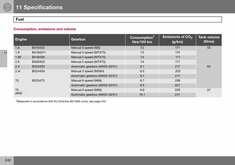
11 Specifications
242
Fuel
11
Consu
EnginEmissions of CO2
(g/km)Tank volume
(litres)
1.6 171 551.8 1741.8F 1772.0 1772.4 217 622.4i 203
217T5 208
227T5 AWD
229 57241
1Measu
mption, emissions and volume
e Gearbox Consumption1
litre/100 km
B4164S3 Manual 5 speed (IB5) 7.2B4184S11 Manual 5 speed (MTX75) 7.3B4184S8 Manual 5 speed (MTX75) 7.4B4204S3 Manual 5 speed (MTX75) 7.4B5244S5 Automatic gearbox (AW55-50/51) 9.1B5244S4 Manual 5 speed (M56H) 8.5
Automatic gearbox (AW55-50/51) 9.1B5254T3 Manual 6 speed (M66) 8.7
Automatic gearbox (AW55-50/51) 9.5Manual 6 speed (M66) 9.6Automatic gearbox (AW55-50/51) 10.1
red in accordance with EU Directive 80/1268 comb, see page 244.
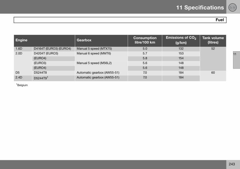
11 Specifications
243
Fuel
11
EnginEmissions of CO2
(g/km)Tank volume
(litres)
1.6D 132 522.0D 153
154148148
D5 184 602.4D 184
1Belgiu
e GearboxConsumptionlitre/100 km
D4164T (EURO3) (EURO4) Manual 5 speed (MTX75) 5.0D4204T (EURO3) Manual 6 speed (MMT6) 5.7(EURO4) 5.8(EURO3) Manual 5 speed (M56L2) 5.6(EURO4) 5.6D5244T8 Automatic gearbox (AW55-51) 7.0
D5244T91 Automatic gearbox (AW55-51) 7.0
m
11 Specifications
244
Fuel
11
Fuel cocarbon
Official fon a stawith EUsumptioequippethe car’sis drivenaffect fuhigher aan octan
DieselThe diesel engine’s fuel system is sensitive to contaminants, see page 183.
nsumption and emissions of dioxide
uel consumption figures are based ndard driving cycle in accordance Directive 80/1268 comb. Fuel con-n figures may change if the car is d with extra equipment that affects weight. The manner in which the car and other non-technical factors can el consumption. Consumption is nd power output lower for fuel with e rating of 91 RON.
Petrol Most engines can be run with octane ratings of 91, 95 and 98 RON.
• 91 RON must not be used for 4-cylinder engines and should only be used in ex-ceptional cases with other engines.
• 95 RON can be used for normal driving.• 98 RON is recommended for optimum
performance and minimum fuel consump-tion.
When driving in temperatures above +38 ºC, fuel with the highest possible octane rating is recommended for optimum performance and fuel economy.
Petrol – Norm EN 228.
IMPORTANT
Use only unleaded petrol to avoid damag-ing the catalytic converter. In order for the Volvo warranty to apply, never mix alcohol with petrol, the fuel system could be dam-aged.
11 Specifications
245
Catalytic converter
11
Genera
The purpurify exof exhauit quicklcatalytic(ceramicnel wallsnum, rhact as cacceleraused up
l
pose of the catalytic converter is to haust gases. It is located in the flow st gasses close to the engine so that
y reaches operating temperature. The converter consists of a monolith or metal) with channels. The chan- are lined with a thin layer of plati-
odium and palladium. These metals atalysts, i.e. they participate in and te a chemical reaction without being themselves.
Lambda-sondTM oxygen sensor The Lambda-sond is part of a control system intended to reduce emissions and improve fuel economy.
An oxygen sensor monitors the oxygen con-tent of the exhaust gases leaving the engine. This value is fed into an electronic system that continuously controls the injectors. The ratio of air to fuel is continuously adjusted. These adjustments create optimal condi-tions for efficient combustion, and together with the three-way catalytic converter reduce harmful emissions (hydrocarbons, carbon monoxide and nitrous oxides).
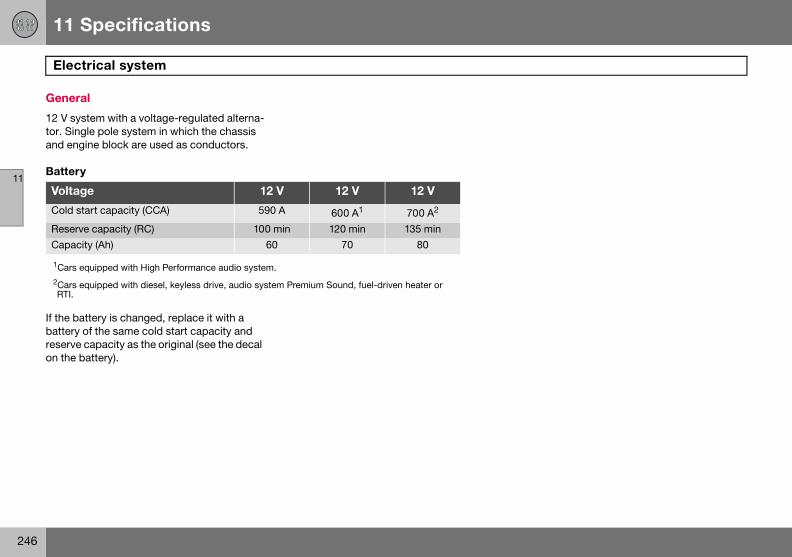
11 Specifications
246
Elect
11
Genera
12 V systor. Singand eng
Battery
If the babattery reserve on the b
Voltag
Cold st
ReservCapaci
1Cars e2Cars eRTI.
rical system
l
tem with a voltage-regulated alterna-le pole system in which the chassis ine block are used as conductors.
ttery is changed, replace it with a of the same cold start capacity and capacity as the original (see the decal attery).
e 12 V 12 V 12 V
art capacity (CCA) 590 A 600 A1 700 A2
e capacity (RC) 100 min 120 min 135 minty (Ah) 60 70 80
quipped with High Performance audio system.
quipped with diesel, keyless drive, audio system Premium Sound, fuel-driven heater or
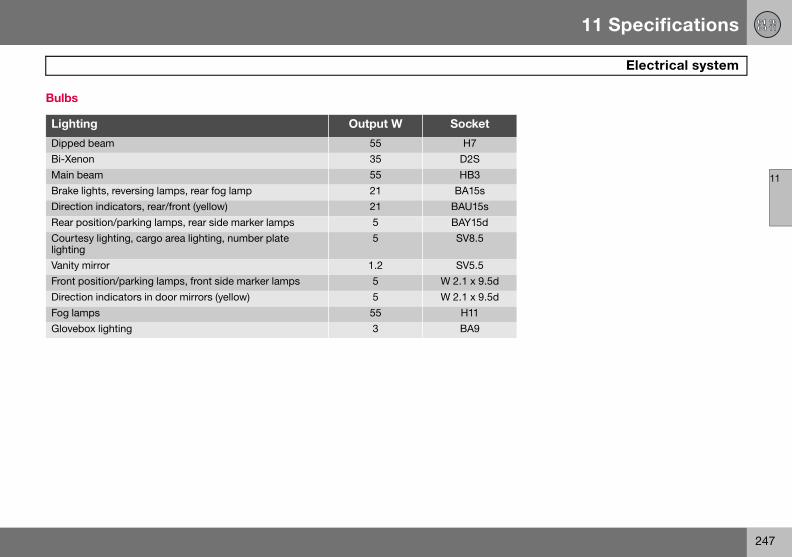
11 Specifications
247
Electrical system
11
Bulbs
Lighti
DippedBi-XenMain bBrake lDirectioRear poCourtelightingVanity mFront pDirectioFog lamGloveb
ng Output W Socket
beam 55 H7on 35 D2Seam 55 HB3ights, reversing lamps, rear fog lamp 21 BA15sn indicators, rear/front (yellow) 21 BAU15ssition/parking lamps, rear side marker lamps 5 BAY15d
sy lighting, cargo area lighting, number plate
5 SV8.5
irror 1.2 SV5.5osition/parking lamps, front side marker lamps 5 W 2.1 x 9.5dn indicators in door mirrors (yellow) 5 W 2.1 x 9.5dps 55 H11
ox lighting 3 BA9
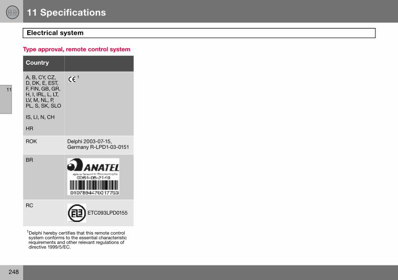
11 Specifications
248
Elect
11
Type a
Count
A, B, CD, DK, F, FIN, GH, I, IRLV, M, NPL, S, S
IS, LI, N
HR
1Delphisystemrequiredirecti
ROK
BR
RC
rical system
pproval, remote control system
ry
Y, CZ, E, EST,
B, GR, L, L, LT,
L, P, K, SLO
, CH
1
hereby certifies that this remote control conforms to the essential characteristic ments and other relevant regulations of
ve 1999/5/EC.
Delphi 2003-07-15, Germany R-LPD1-03-0151
ETC093LPD0155
11 Specifications
249
11
Alphabetical index
250
AA/C .....
electmanu
ABS ....ABS
Active YAdditionAF – autAir cond
ECCgene
Air distriECC
Air qualiAir ventsAirbag
deacdrive
Alarmalarmalarmarminautomdeacdisargenetestin
BBackrest
rear seat, tipping .................................... 90Bass speaker ............................................ 209Battery
care ...................................................... 190jump starting ........................................ 139overload ............................................... 117replacement ......................................... 191replacing the battery in the remote control .................................................. 103symbols on the battery ........................ 191
Blind spot (BLIS) ....................................... 134Bonnet ...................................................... 182Booster cushion
lowering ................................................. 32raising .................................................... 31
Booster cushion, integrated ....................... 31Brake fluid, checking and topping up ....... 187Brake system .................................... 128, 187Brakes
handbrake .............................................. 59Bulb holder
location of the bulbs ............................ 196number plate lighting ........................... 196removal ................................................ 195
Bulbsreplacement ......................................... 192
.........................................................74ronic climate control .......................78al climate control ...........................75
.......................................................128fault ................................................43aw Control ...................................130al heater .........................................81omatic frequency update .............214itioning ...........................................74 ........................................................76ral ...................................................72bution .............................................79 ........................................................78ty system, ECC ..............................77 ......................................................73
tivation ...........................................20r’s and front passenger side ..........16
light ............................................111 signals ........................................112g ..................................................111atic alarm activation ...................112
tivating a triggered alarm .............112ming .............................................111ral .................................................111g the alarm system ......................113
Alarm, radio functions .............................. 212All-wheel drive .......................................... 127Approach light duration
active lamps .......................................... 64setting .................................................... 69
Audio volumeaudio system ....................................... 209media player ........................................ 209
Audio, see also Sound ............................. 209AUTO
climate control settings ......................... 76preset storage ..................................... 211
AUTO CLIMATE .......................................... 76Auto volume control ................................. 210Automatic car wash .................................. 172Automatic dimming .................................... 62Automatic gearbox ................................... 124
safety systems .................................... 124towing and recovery ............................ 137trailer ........................................... 140, 141W-button ............................................. 126
Automatic locking ..................................... 107Automatic relocking .................................. 107Autostart ................................................... 119Average fuel consumption .......................... 52AWD ......................................................... 127
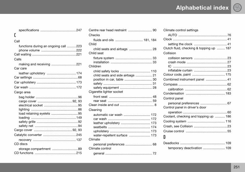
Alphabetical index
251
spec
CCall
functphon
Call waiCalls
makiCar care
leathCar settCar uphCar wasCargo a
bag hcargoelectlightiload loadisafetsafet
Cargo cCatalytic
recovCD disc
storaCD func
Climate control settingsAUTO ..................................................... 76
Clock ........................................................... 41setting the clock .................................... 41
Clutch fluid, checking & topping up ......... 187Collision
collision sensors .................................... 23crash mode ............................................ 27IC ........................................................... 23inflatable curtain .................................... 23
Colour code, paint .................................... 175Combined instrument panel ....................... 41Compass ..................................................... 62
calibration .............................................. 62Condensation ........................................... 183Control panel
personal preferences ............................. 67Control panel in driver’s door
operation ................................................ 60Coolant, checking and topping up ........... 186Cooling system ......................................... 116Crash, see Collision .................................... 23Cruise control ............................................. 55
DDeadlocks ................................................. 109
temporary deactivation ........................ 109
ifications .......................................247
ions during an ongoing call ..........223e volume ......................................222ting ................................................221
ng and receiving ...........................221
er upholstery ................................174ings .................................................68olstery ...........................................173h ...................................................172reaolder ..............................................96 cover ......................................92, 93
rical socket .....................................95ng ...................................................86retaining eyelets .............................95ng .................................................149y grille .............................................92y net ...............................................94over ..........................................92, 93 converter ....................................245ery ...............................................137
sge compartment ............................89tions .............................................215
Centre rear head restraint .......................... 90Checks
fluids and oils .............................. 181, 184Child
child seats and airbags ......................... 28Child seat
fixture system ........................................ 33installation ............................................. 33
Childrenchild safety locks ................................. 110child seats and side airbags .................. 21position in car, table .............................. 30safety ..................................................... 31safety equipment ................................... 28
Cigarette lighter socketfront seat ............................................... 48rear seat ................................................ 59
Clean inside and out ..................................... 8Cleaning
automatic car wash ............................. 172car wash .............................................. 172leather upholstery ................................ 173seatbelts .............................................. 174upholstery ............................................ 173water-repellent surface ....................... 173
Climatepersonal preferences ............................. 68
Climate controlgeneral ................................................... 72

Alphabetical index
252
tempdetec
Defrostedoorrear w
DesignaDiesel .
enginDiesel fiDiesel pDipped DirectionDisc texDisplay
messDisplay Dolby SDoor miDriver’s
overvDriving
advecoolieconslippwith with
Driving i
changing .............................................. 184driving under adverse driving conditions ............................................ 236filter ...................................................... 184oil grade ............................................... 236oil pressure ............................................ 44
Engine specifications ................................ 234Entry, keyless .............................................. 69Environmental philosophy ............................ 7EON – Enhanced Other Networks ............ 214Equalizer ................................................... 210Expectant mothers
safety ..................................................... 13
FFan .............................................................. 74
ECC ....................................................... 76Fast-wind .................................................. 216Floor mats ................................................... 84Fluids and oils
checks ......................................... 181, 184Fluids, capacities .............................. 240, 241Fog lamps, On/Off ...................................... 53Frequency update, automatic ................... 214Fuel
consumption .................................... 7, 242fuel consumption, display ...................... 52fuel economy ....................................... 158
orary disconnection of alarm tors ..............................................112r .....................................................75
mirrors ...........................................75indow ...........................................75
tion of dimensions ........................154.......................................................183e preheater ....................................43
lter ................................................183article filter ....................................119beam ........................................49, 51 indicators .....................................51
t ....................................................216
ages .........................................46, 47lighting ............................................50urround Pro Logic II ..............208, 210rrors ................................................64door control paneliew .................................................40
rse driving conditions ...................180ng system .....................................116omical ...........................................116ery driving conditions ...................116open tailgate .................................116trailer ............................................140n water .........................................116
DSTC, see also Stability control system .. 130DSTC, see also Stability system
deactivating/activating ........................ 130symbol ................................................... 43
EECC, electronic climate control .................. 73ECO pressure
fuel economy ....................................... 158table ..................................................... 159
Economical driving ................................... 116Electrical socket
cargo area ............................................. 95centre console ....................................... 48rear seat ................................................ 59
Electronic immobiliser .............................. 100Emergency calls ....................................... 219Emergency puncture repair ...................... 163Emission control ........................................... 7Emissions ................................................. 242
carbon dioxide .................................... 244
Emissions systemfault indicator ......................................... 43
Engine ....................................................... 182Engine compartment ................................ 182Engine oil .................................................. 184
capacities ............................ 237, 238, 239
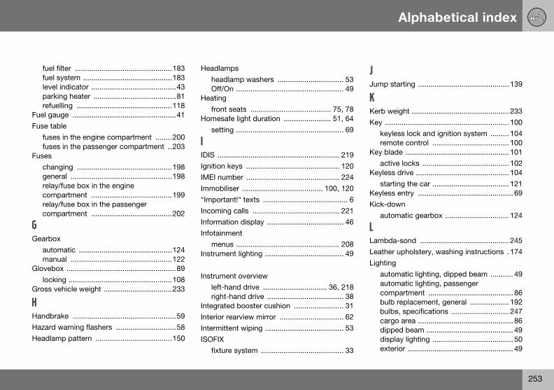
Alphabetical index
253
fuel ffuel slevel parkirefue
Fuel gauFuse tab
fusesfuses
Fuseschangenerelaycomprelaycomp
GGearbox
autommanu
Glovebolocki
Gross ve
HHandbraHazard Headlam
JJump starting ............................................ 139
KKerb weight ............................................... 233Key ............................................................ 100
keyless lock and ignition system ......... 104remote control ..................................... 100
Key blade .................................................. 101active locks .......................................... 102
Keyless drive ............................................. 104starting the car ..................................... 121
Keyless entry .............................................. 69Kick-down
automatic gearbox ............................... 124
LLambda-sond ........................................... 245Leather upholstery, washing instructions . 174Lighting
automatic lighting, dipped beam ........... 49automatic lighting, passenger compartment ......................................... 86bulb replacement, general ................... 192bulbs, specifications ............................ 247cargo area .............................................. 86dipped beam .......................................... 49display lighting ....................................... 50exterior ................................................... 49
ilter ...............................................183ystem ...........................................183indicator .........................................43ng heater ........................................81lling ..............................................118ge ..................................................41le in the engine compartment ........200 in the passenger compartment ..203
ging ..............................................198ral .................................................198/fuse box in the engine artment .......................................199
/fuse box in the passenger artment .......................................202
atic .............................................124al .................................................122x .....................................................89ng ..................................................108hicle weight .................................233
ke ..................................................59warning flashers .............................58p pattern .....................................150
Headlampsheadlamp washers ................................ 53Off/On .................................................... 49
Heatingfront seats ....................................... 75, 78
Homesafe light duration ....................... 51, 64setting .................................................... 69
IIDIS ........................................................... 219Ignition keys ............................................. 120IMEI number ............................................. 224Immobiliser ....................................... 100, 120"Important!" texts ......................................... 6Incoming calls .......................................... 221Information display ..................................... 46Infotainment
menus .................................................. 208Instrument lighting ...................................... 49
Instrument overviewleft-hand drive ............................... 36, 218right-hand drive ..................................... 38
Integrated booster cushion ........................ 31Interior rearview mirror ............................... 62Intermittent wiping ...................................... 53ISOFIX
fixture system ........................................ 33

Alphabetical index
254
frontheadhomein painstrulightimainpositreadirear f
Lightingcargocourtdippedirecfog lafrontlocatmainparkipositrear lside vanit
Lightsmain
Loadingcargogeneload
NNEWS ....................................................... 213News broadcast ........................................ 213"Note" texts .................................................. 6
OOil, see also Engine oil
oil pressure ............................................ 44Outside temperature gauge ........................ 41Oxyhydrogen gas ...................................... 139
PPACOS ........................................................ 19Paint
paintwork damage and touching up .... 175Paintwork
colour code .......................................... 175Parking assistance .................................... 132
sensors for parking assistance ............ 133Parking brake ........................................ 44, 59Parking heater
battery and fuel ...................................... 81general ................................................... 80parking on a hill ..................................... 80time setting ............................................ 81
Parking lamps ............................................. 49
fog lamps .......................................53lamp levelling .................................49safe light duration ...................51, 64
ssenger compartment ....................86ment lighting .................................50
ng panel ..........................................49/dipped beam .................................51ion/parking lamps ..........................49ng lamps ........................................86og lamp ..........................................50, bulb replacement area ............................................197esy lighting ...................................196d beam ........................................193
tion indicators ..............................194mp ...............................................195
......................................................192ion of the bulbs in the bulb holder 196 beam ...........................................193ng lamps ......................................194ion lamps ......................................194amp ..............................................195marker lamps ...............................194y mirror .........................................197
beam "flash" ..................................51
area ..............................................95ral .................................................149capacity ........................................149
Lock settings, personal .............................. 67Locking ..................................................... 107
from inside ........................................... 108from outside ........................................ 107unlocking ............................................. 107
Lubricants, capacities ...................... 240, 241
MMain beam .................................................. 51
Off/On .................................................... 49switching and flashing ........................... 51
Maintenancerustproofing ......................................... 176self-maintenance ................................. 181
Making calls .............................................. 221Manual gearbox ........................................ 122Menu structure
media player ........................................ 217phone, menu options .......................... 226phone, overview .................................. 225
Menusaudio system ....................................... 208
Messages in the information display .......... 46Misting
rear window ........................................... 75removing with defroster function .... 75, 77timer function, A/C ................................ 75timer function, ECC ............................... 77treating the windows ............................. 72
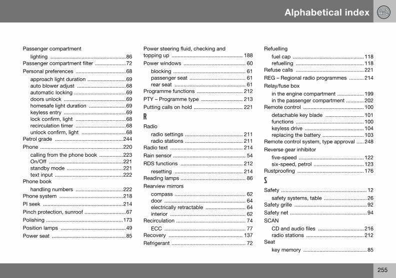
Alphabetical index
255
Passenglighti
PassengPersona
apprauto automdoorhomekeylelock recircunloc
Petrol gPhone .
callinOn/Ostandtext i
Phone bhand
Phone sPI seek Pinch prPolishinPositionPower s
Refuellingfuel cap ................................................ 118refuelling .............................................. 118
Refuse calls .............................................. 221REG – Regional radio programmes .......... 214Relay/fuse box
in the engine compartment .................. 199in the passenger compartment ............ 202
Remote control ......................................... 100detachable key blade .......................... 101functions .............................................. 100keyless drive ........................................ 104replacing the battery ............................ 103
Remote control system, type approval ..... 248Reverse gear inhibitor
five-speed ............................................ 122six-speed, petrol .................................. 123
Rustproofing ............................................. 176
SSafety .......................................................... 12
safety systems, table ............................. 26Safety grille ................................................. 92Safety net .................................................... 94SCAN
CD and audio files ............................... 216radio stations ....................................... 212
Seatkey memory ........................................... 85
er compartmentng ...................................................86er compartment filter .....................72l preferences ..................................68oach light duration ..........................69blower adjust .................................68
atic locking ...................................69s unlock ..........................................69safe light duration .........................69ss entry ..........................................69confirm, light ..................................68ulation timer ..................................68k confirm, light ..............................68
rade ..............................................244.......................................................220g from the phone book ................223ff ..................................................221by mode ......................................221
nput ..............................................222ookling numbers ................................222ystem ...........................................218......................................................214otection, sunroof ............................67g ....................................................173 lamps ............................................49eat ..................................................85
Power steering fluid, checking and topping up ................................................ 188Power windows .......................................... 60
blocking ................................................. 61passenger seat ...................................... 61rear seat ................................................ 61
Programme functions ............................... 212PTY – Programme type ............................ 213Putting calls on hold ................................. 221
RRadio
radio settings ....................................... 211radio stations ....................................... 211
Radio text ................................................. 214Rain sensor ................................................. 54RDS functions .......................................... 212
resetting .............................................. 214Reading lamps ............................................ 86Rearview mirrors
compass ................................................ 62door ....................................................... 64electrically retractable ........................... 64interior ................................................... 62
Recirculation ............................................... 74ECC ....................................................... 77
Recovery .................................................. 137Refrigerant .................................................. 72
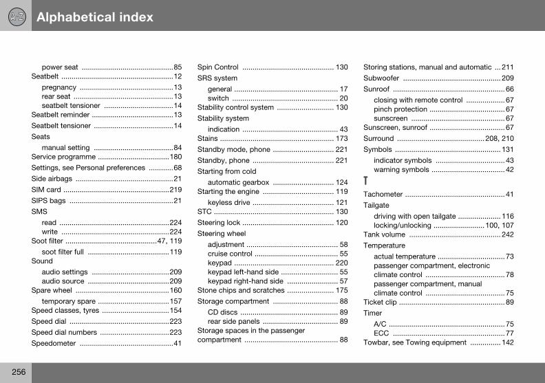
Alphabetical index
256
poweSeatbelt
pregnrear sseatb
SeatbeltSeatbeltSeats
manuService SettingsSide airbSIM carSIPS baSMS
read write
Soot filtesoot
Soundaudioaudio
Spare wtemp
Speed cSpeed dSpeed dSpeedo
Storing stations, manual and automatic ... 211Subwoofer ................................................ 209Sunroof ....................................................... 66
closing with remote control ................... 67pinch protection ..................................... 67sunscreen .............................................. 67
Sunscreen, sunroof ..................................... 67Surround ........................................... 208, 210Symbols .................................................... 131
indicator symbols .................................. 43warning symbols .................................... 42
TTachometer ................................................. 41Tailgate
driving with open tailgate ..................... 116locking/unlocking ......................... 100, 107
Tank volume ............................................. 242Temperature
actual temperature ................................. 73passenger compartment, electronic climate control ....................................... 78passenger compartment, manual climate control ....................................... 75
Ticket clip .................................................... 89Timer
A/C ......................................................... 75ECC ....................................................... 77
Towbar, see Towing equipment ............... 142
r seat .............................................85 .......................................................12ancy ..............................................13eat .................................................13elt tensioner ..................................14 reminder ........................................13 tensioner .......................................14
al setting .......................................84programme ...................................180, see Personal preferences ............68ags ................................................21
d ....................................................219gs ...................................................21
......................................................224 .....................................................224r .............................................47, 119
filter full ........................................119
settings ......................................209 source ........................................209heel ..............................................160orary spare ...................................157lasses, tyres .................................154ial .................................................223ial numbers ..................................223
meter ..............................................41
Spin Control ............................................. 130SRS system
general ................................................... 17switch .................................................... 20
Stability control system ............................ 130Stability system
indication ............................................... 43Stains ........................................................ 173Standby mode, phone .............................. 221Standby, phone ........................................ 221Starting from cold
automatic gearbox .............................. 124Starting the engine ................................... 119
keyless drive ........................................ 121STC ........................................................... 130Steering lock ............................................. 120Steering wheel
adjustment ............................................. 58cruise control ......................................... 55keypad ................................................. 220keypad left-hand side ............................ 55keypad right-hand side ......................... 57
Stone chips and scratches ....................... 175Storage compartment ................................ 88
CD discs ................................................ 89rear side panels ..................................... 89
Storage spaces in the passenger compartment .............................................. 88
Alphabetical index
257
Towing Towing
geneinstaremospec
Towing TP – traTractionTractionTraffic inTrailer
cabledrivintraile
Trip comTrip metTuning Type apType deTyre
pressTyres
desigdirecdrivinECOgene
rear window ........................................... 54Washer fluid, topping up .......................... 186Washers
windscreen and headlamps ................... 53Washing the car ........................................ 172Waxing ...................................................... 173Wheels
fitting .................................................... 162removal ................................................ 161rims ...................................................... 156
Whiplash injury WHIPS ............................... 24WHIPS ........................................................ 24
child seat/booster cushion .................... 24Windscreen wipers
rain sensor ............................................. 54Windscreen wipers and washers ................ 53Winter driving ............................................ 119Winter tyres ............................................... 155Wiper
rear window ........................................... 54Wiper blades
replacing, rear window ........................ 189replacing, windscreen .......................... 189
......................................................137equipmentral .................................................142llation ............................................144ving ..............................................147ifications .......................................143eye ................................................137ffic information ..............................212 control .........................................130 control system ............................130formation .....................................212
....................................................142g with a trailer ..............................140r weight ........................................233puter ..............................................52er ....................................................41.......................................................211proval, remote control system .....248signation .......................................232
ure ...............................................158
nation of dimensions ...................154tion of rotation ..............................157g characteristics ..........................154
pressure .......................................159ral .................................................154
puncture repair .................................... 163speed classes ...................................... 154summer and winter wheels ................. 157tread wear indicators ........................... 155winter tyres .......................................... 155
UUnlocking
from inside ........................................... 108from outside ........................................ 107keyless ................................................. 107settings .................................................. 68tailgate ................................................. 107
VVehicle data .............................................. 180Ventilation ................................................... 73Volume
auto volume control ............................ 210phone/media player ............................ 222programme types ................................ 214
Volume, see also Audio volume ............... 209
WWarning lamp
stability and traction control system ... 130Warning symbol, AIRBAG system .............. 15"Warning!" texts ........................................... 6Warning triangle ....................................... 160Washer

Volvo Car Corporation TP 8970 ( English), AT 0646, Printed in Sweden, Göteborg 2006, Copyright © 2000-2006 Volvo Car Corporation
Volvo. for life