v3f manual
TRANSCRIPT

8/11/2019 V3F Manual
http://slidepdf.com/reader/full/v3f-manual 1/33
VersaSTAT 3F
Hardware Manual

8/11/2019 V3F Manual
http://slidepdf.com/reader/full/v3f-manual 2/33
VersaSTAT 3F Electrochemical System
1. INTRODUCTION
1.1. HARDWARE
1.2. POTENTIOSTATIC CIRCUITRY
1.2.1. Potentiostatic mode
1.2.2. Galvanostatic mode
1.3. Software
1.4. Polarity Convention
1.5. Inspecting Your New Instrument
1.6. Maintenance, Service, and Support
1.7. About this manual
2. SAFETY AND COMPONENT PLACEMENT
2.1. Safety Considerations
2.1.1. Line Voltage Settings and Fuses
2.1.2. Defects and Abnormal Stresses
2.2. Component Placement
2.2.1. Ventilation
2.2.2. Radio Frequency Interference
2.2.3. Transient Sensitivity
8/11/2019 V3F Manual
http://slidepdf.com/reader/full/v3f-manual 3/33
3. INSTALLATION
3.1. Enabling the USB port on your PC
3.2. Connectors and Indicators
3.2.1. Rear Panel
3.2.1.1. INPUT POWER
3.2.1.2. USB
3.2.1.3. SYNC ADC INPUT
3.2.1.4. DAC OUTPUT
3.2.1.5. AUXILIARY INTERFACE
3.2.2. Front Panel
3.2.2.1. CELL CABLE
3.2.2.2. INDICATORS
3.3. Connecting to the PC and Cell
3.3.1. Connecting to the PC
3.3.1.1. INSTALLING THE USB DRIVER
3.3.2. Connecting the Cell
3.4. Floating Operation
3.4.1. Setting Operation Modes of Float and Normal
8/11/2019 V3F Manual
http://slidepdf.com/reader/full/v3f-manual 4/33
4. SPECIFICATIONS AND PINOUTS
4.1. Electronic Specifications
4.1.1. System Performance
4.1.2. Power Amplifier
4.1.3. Voltage Control
4.1.4. Current Control
4.1.5. Differential Electrometer
4.1.6. Voltage Measurement
4.1.7. Current Measurement
4.1.8. iR Compensation
4.1.9. Potential/Current Control
4.1.10. Impedance Specifications (if option available)
4.2. Physical and Power Specifications
4.3. Standard Environmental Conditions
4.4. AUXILIARY INTERFACE Pinouts
4.5. CELL CABLE Pinouts

8/11/2019 V3F Manual
http://slidepdf.com/reader/full/v3f-manual 5/33
5. AVAILABLE OPTIONS
5.1. 2A High Current Option
5.2. FRA Option
5.3. Advanced Auxiliary Interface Option
5.4. Power Booster Options
6. WARRANTY
APPENDIX 1 – VersaSTAT 3F External Power Booster Connections

8/11/2019 V3F Manual
http://slidepdf.com/reader/full/v3f-manual 6/33
Safety Instructions and Symbols
This manual contains up to three levels of safety instructions that must be observed in order toavoid personal injury and/or damage to equipment or other property. These are:
DANGER Indicates a hazard that could result in death or serious bodily harm if the safety
instruction is not observed.
WARNING Indicates a hazard that could result in bodily harm if the safety instruction is
not observed.
CAUTION Indicates a hazard that could result in property damage if the safety instruction
is not observed.
Please read all safety instructions carefully and make sure you understand them fully before
attempting to use this product.
Cleaning Instructions
WARNING: Using this instrument in a manner not specified by the manufacturer may
impair the protection provided by the instrument.
To clean the instrument exterior:
•
Unplug the instrument from all voltage sources.• Remove loose dust on the outside of the instrument with a lint-free cloth.
• Remove remaining dirt with a lint-free cloth dampened in a general-purpose detergent and
water solution. Do not use abrasive cleaners.
CAUTION: To prevent moisture inside of the instrument during external cleaning, use
only enough liquid to dampen the cloth or applicator.
• Allow the instrument to dry before reconnecting the power cord.

8/11/2019 V3F Manual
http://slidepdf.com/reader/full/v3f-manual 7/33
1. INTRODUCTION
The VersaSTAT 3F (Figure 1), teamed with the VersaStudio software package, comprises a
simple, flexible, and extremely powerful system for performing a wide range of electrochemical
techniques. The VersaSTAT 3F is a potentiostat/galvanostat with an optional frequencyresponse analyzer (FRA) contained in a single unit. It is controlled from any suitably equipped
PC by a Universal Serial Bus (USB) interface using the VersaStudio electrochemistry software package.
Figure 1. VersaSTAT 3F
1.1. General
The host computer provides memory, data processing, input-output, and interface capabilities.
The VersaSTAT 3F electronically controls the measurement under the direction of the software
and parameter values entered from the host computer. The computer must be equipped with aUSB port, and the operating system must support the USB interface.
1.2. Hardware Circuitry
The VersaSTAT 3F circuitry includes:
• Two 16-bit digital-to-analog converters (DACs) for versatile waveform generation.
• Three 16-bit analog-to-digital converters (ADCs) to measure current (I), potential (E), SYNCADC INPUT.
• An onboard microprocessor to perform the experiment defined by the operating software.
•
Onboard memory to store the programmed parameters and data point values.
The VersaSTAT 3F operates with VersaStudio in either the potentiostatic or galvanostatic mode,
described below.
1.2.1. Potentiostatic mode
8/11/2019 V3F Manual
http://slidepdf.com/reader/full/v3f-manual 8/33
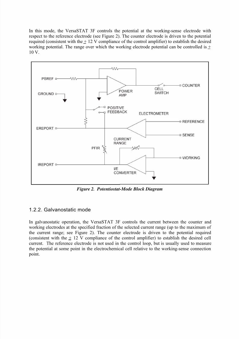
In this mode, the VersaSTAT 3F controls the potential at the working-sense electrode with
respect to the reference electrode (see Figure 2). The counter electrode is driven to the potentialrequired (consistent with the + 12 V compliance of the control amplifier) to establish the desired
working potential. The range over which the working electrode potential can be controlled is +
10 V.
Figure 2. Potentiostat-Mode Block Diagram
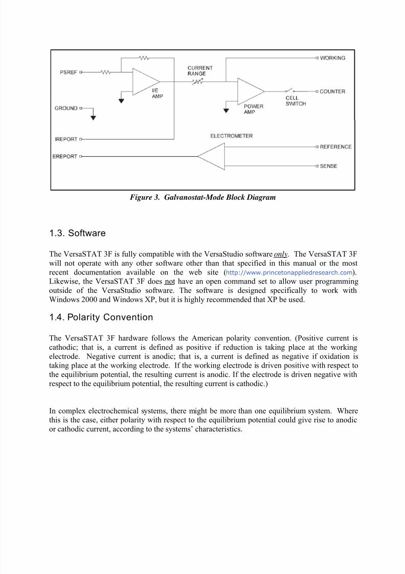
1.2.2. Galvanostatic mode
In galvanostatic operation, the VersaSTAT 3F controls the current between the counter andworking electrodes at the specified fraction of the selected current range (up to the maximum of
the current range; see Figure 2). The counter electrode is driven to the potential required
(consistent with the + 12 V compliance of the control amplifier) to establish the desired cellcurrent. The reference electrode is not used in the control loop, but is usually used to measure
the potential at some point in the electrochemical cell relative to the working-sense connection point.
8/11/2019 V3F Manual
http://slidepdf.com/reader/full/v3f-manual 9/33
Figure 3. Galvanostat-Mode Block Diagram
1.3. Software
The VersaSTAT 3F is fully compatible with the VersaStudio software only. The VersaSTAT 3F
will not operate with any other software other than that specified in this manual or the most
recent documentation available on the web site (http://www.princetonappliedresearch.com).Likewise, the VersaSTAT 3F does not have an open command set to allow user programming
outside of the VersaStudio software. The software is designed specifically to work with
Windows 2000 and Windows XP, but it is highly recommended that XP be used.
1.4. Polarity Convention
The VersaSTAT 3F hardware follows the American polarity convention. (Positive current is
cathodic; that is, a current is defined as positive if reduction is taking place at the working
electrode. Negative current is anodic; that is, a current is defined as negative if oxidation istaking place at the working electrode. If the working electrode is driven positive with respect to
the equilibrium potential, the resulting current is anodic. If the electrode is driven negative with
respect to the equilibrium potential, the resulting current is cathodic.)
In complex electrochemical systems, there might be more than one equilibrium system. Wherethis is the case, either polarity with respect to the equilibrium potential could give rise to anodic
or cathodic current, according to the systems’ characteristics.

8/11/2019 V3F Manual
http://slidepdf.com/reader/full/v3f-manual 10/33
1.5. Inspecting Your New Instrument
As soon as you receive your new VersaSTAT 3F, inspect it for shipping damage. If any damage
is noted, immediately notify Princeton Applied Research and file a claim with the carrier. Save
the shipping container for possible inspection by the carrier.
WARNING: If your instrument has been damaged, its protective grounding might not
work. Do not operate damaged equipment! Tag it to indicate to a potential
user that it is unsafe to operate.
1.6. Maintenance, Service, and Support
The VersaSTAT 3F has been designed for optimum reliability and requires no periodic
maintenance. There are no user-serviceable parts in this instrument. Breaking the seal by
opening the cover will void your warranty! Contact the factory service department or the
affiliate in your area if your unit needs service (see the Warranty in Section 5. for more
information).
Remember that our worldwide staff continues to support you after you have purchased your
instrument. We provide top quality service, applications support, and a variety of helpful
information in the form of application notes, technical notes, and training materials. For moreinformation, visit our website at www.princetonappliedresearch.com.
1.7. About this manual
Chapter 2 describes recommended safety precautions for operating this instrument, includingthe provision of adequate ventilation. It also tells how to deal with transients on the power line,and discusses the unlikely possibility of the instrument causing radio frequency (RF)interference.
Chapter 3 shows how to set up the hardware. It describes the functions of the connections and
indicator lights, and shows how to connect the VersaSTAT 3F to the host computer and test cell.
Chapter 4 gives the physical and electrical specifications of the VersaSTAT 3F including the
AUXILIARY INTERFACE connector pinouts.
As noted above, the VersaSTAT 3F is completely computer controlled; operation andexperimental procedures are covered in the software section of this manual.
8/11/2019 V3F Manual
http://slidepdf.com/reader/full/v3f-manual 11/33
2. SAFETY AND COMPONENT PLACEMENT
This chapter lists safety precautions for use when operating the VersaSTAT 3F; please read
them. There are suggestions for system component placement and information on possible RF
interference and transient sensitivity.
2.1. Safety Considerations
2.1.1. Line Voltage Settings and Fuses
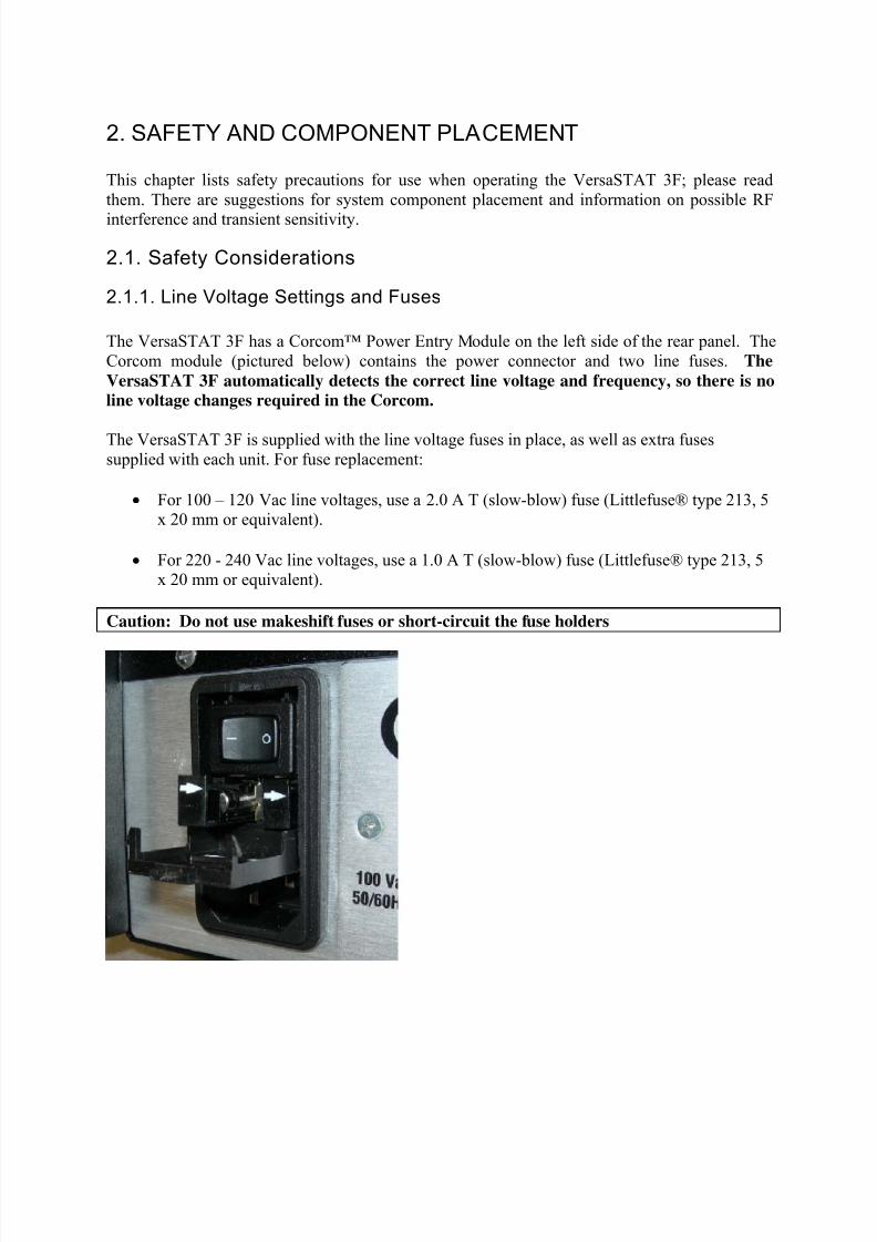
The VersaSTAT 3F has a Corcom™ Power Entry Module on the left side of the rear panel. The
Corcom module (pictured below) contains the power connector and two line fuses. The
VersaSTAT 3F automatically detects the correct line voltage and frequency, so there is no
line voltage changes required in the Corcom.
The VersaSTAT 3F is supplied with the line voltage fuses in place, as well as extra fusessupplied with each unit. For fuse replacement:
• For 100 – 120 Vac line voltages, use a 2.0 A T (slow-blow) fuse (Littlefuse® type 213, 5
x 20 mm or equivalent).
• For 220 - 240 Vac line voltages, use a 1.0 A T (slow-blow) fuse (Littlefuse® type 213, 5x 20 mm or equivalent).
Caution: Do not use makeshift fuses or short-circuit the fuse holders
8/11/2019 V3F Manual
http://slidepdf.com/reader/full/v3f-manual 12/33
To replace a fuse:
1. Disconnect the instrument for the ac power source.
2. Use a small flat-blade screwdriver or similar tool to pop open the module door (as shown
in the picture above).
3.
The line fuse is in a plastic fuse holder “drawer” marked with an arrow ( ). Gently pull the fuse holder out, remove the old fuse, and press in the replacement.
4. Slide the fuse holder back into the module, and close the module door. You are now
ready to reconnect the instrument to the ac power source.
2.1.2. Defects and Abnormal Stresses
WARNING: If your instrument has been damaged, its protective grounding might not
work. Do not operate damaged equipment! Tag it to indicate to a potential
user that it is unsafe to operate.
The VersaSTAT 3F’s ground protection is likely to be impaired if, for example, the instrument
• shows visible damage
• fails to perform the intended measurement.
• has been subjected to prolonged storage under unfavorable conditions, or
• has been subjected to severe transport stresses.
The instrument should not be used until its safety has been verified by qualified service personnel.
2.2. Component Placement
Before assembling the system, give some thought to component placement. You will of course
need convenient access to the computer keyboard and, if applicable, the printer. Depending onthe application, you might also need to connect and disconnect the cell leads regularly.
When you are satisfied that the system is ready to install, connect the units according to the
instructions in Chapter 3.
NOTE: The standard system does not include an electrochemical cell. You must supply a
suitable cell and electrodes.
2.2.1. Venti lation
VersaSTAT 3F specifications apply at the nominal line voltage + and at a temperature of 25o C
(77 o
F) unless otherwise noted. Ambient temperature must not exceed 50o C (122
o F). See
Section 4.3 for more detailed environmental specifications.

8/11/2019 V3F Manual
http://slidepdf.com/reader/full/v3f-manual 13/33
To maintain a safe operating temperature, allow some free space (minimum 10 cm) at either sideof the VersaSTAT 3F for adequate air circulation. There must be adequate circulation between
the spaces at the sides of the instrument and the ambient laboratory air. In a typical bench top
installation, these requirements are satisfied with a large safety margin.
CAUTION Because the ventilation for the VersaSTAT 3F is on the side panels, rack
mounting in an enclosed cabinet is not recommended.
2.2.2. Radio Frequency Interference
In a typical application, it is unlikely that the VersaSTAT 3F will act as a source of noticeableRF interference. However, when operated near particularly sensitive equipment, interference
from the VersaSTAT 3F could be a problem.
Below is a discussion of steps you can take to minimize that interference.
Interference below about 10 MHz is most likely to be caused by RF currents flowing in the inputand output cables or in the power line cord.
If excessive noise pickup is present, try decoupling the power line with an external filter. At
frequencies below 100 kHz, an external isolation transformer could be helpful.
WARNING: To reduce the risk of potentially dangerous electrical shock, only a qualified
service technician should perform this work, and then only with the
instrument disconnected from all sources of power.
At frequencies above 10 MHz, these measures might not suffice to prevent radiation from being
a problem, particularly at VHF frequencies. Additional measures will then be required.Shielding is generally effective. A suitable shield can be constructed using metal foil, wire
screening, or similar materials.
Once the instrument is completely surrounded by the shield (taking care not to unduly restrict
ventilation), the only additional requirement is to install low-pass filters where lines pass through
the shield (all openings through the shield should be as small as possible). A capacitor between aline and the shield can function as a suitable low-pass filter. The leads of the capacitor should be
as short as possible. We suggest using coaxial feed through capacitors.
In the case of a signal lead, it is essential that the capacitor’s value be such as to attenuate the
interference frequencies without unduly attenuating critical frequency components of the signalitself.
NOTE: Keep the filter capacitor leads short! Long leads establish sizable ground loopsand could additionally act as radiating antennae.

8/11/2019 V3F Manual
http://slidepdf.com/reader/full/v3f-manual 14/33
Coaxial cables are a special case in that the cable shield acts as an extension of the enclosureshield. Thus, the filter can be counted in a shielded box fitted with coaxial connectors without
undue concern for keeping the box extremely close to the enclosure. If more convenient, it can
be located at some distance from the enclosure as long as the integrity of the coaxial shield is
maintained.
The preceding techniques are extraordinary measures that should be required only in unusual
cases. If they are applied with care, RF interference should be reduced to an acceptably lowlevel in all but the most critical applications. Contact the Customer Service Department for
advice in the case of a problem that does not yield to these measures.
2.2.3. Transient Sensi tivi ty
Princeton Applied Research instruments are designed and constructed to ensure normal operation
in the presence of moderate transient levels. Although these provisions are sufficient for
operation in most places where the equipment is used, it is certainly possible for transient levelsin particular environments to be so severe that they make reliable operation uncertain. There are
three general types of high-level transients:
1. Static discharge
Transients from this source generally affect input or output circuits, input circuits that
include MOS field-effect transistors to achieve high input impedance are particularlysusceptible to damage from this source. Damage typically occurs when the charge built
up on a user’s body discharges into an input or output connector as a connection is being
made. Among the factors determining the tendency for charges to build are the kind ofclothing fabrics worn, shoe materials, and the materials in the floor or floor covering.
2. High-level transients generated internal to the place of use
Such transients almost always enter the instrument via the line cord. Possible sources
include heavy-duty electric motors, RF equipment, diathermy machines, arc welder,
spark chambers, and others.
3. Lightning
Transients caused by lightning almost always enter the instrument via the line cord.
Static discharge problems can sometimes be avoided by judiciously selecting the floor covering
in the work area. The simplest approach to the problem is to discharge your body by touching a
grounded metal object just before touching the instrument, particularly when making connectionsto the cell. External line-transient filters can generally suppress transients that enter the
instrument via the line cord. A suitable transient suppressor is available from Princeton AppliedResearch. Various kinds of power-line conditioners are also commercially available.
8/11/2019 V3F Manual
http://slidepdf.com/reader/full/v3f-manual 15/33
3. INSTALLATION
This chapter describes the VersaSTAT 3F connectors and indicators and shows you how to
connect it to the host PC, electrochemical cell, and other equipment you might wish to use with
it. The pinouts for AUXILIARY INTERFACE connector and cell cable connector are listed inSections 4.4. and 4.5., respectively.
3.1. Enabling the USB port on your PC
Some PC manufacturers ship their PCs with the USB port disabled. Check for this before trying
to use the VersaSTAT 3F. If the port is disabled, follow the manufacturer’s instructions for
enabling it.
3.2. Connectors and Indicators
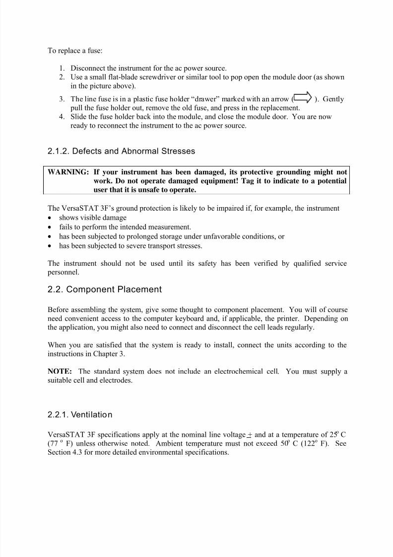
3.2.1. Rear PanelThe VersaSTAT 3F rear panel is shown in Figure 4.
FIGURE 4. VersaSTAT 3F Rear Panel
3.2.1.1. INPUT POWER
120-240-V; the supplied AC power cord can be connected to 120-240V
AC.
3.2.1.2. USB
Attach the supplied USB cable to this connector and to the USB connector
on the PC. You can connect to and disconnect from the PC without
shutting down or restarting Windows or VersaStudio.
3.2.1.3. SYNC ADC INPUTThis BNC allows you to monitor an auxiliary signal in the + 10 V rangewith 16-bit resolution. This signal is monitored synchronously with the
E and I channels.
8/11/2019 V3F Manual
http://slidepdf.com/reader/full/v3f-manual 16/33
3.2.1.4. DAC OUTPUT
Rear-panel BNC delivers a precise DC voltage in the + 10 V range. Thisoutput can be used to control the rotation speed of rotating disk electrodes
(RDEs). CAUTION: The voltage at this connection will be random at
power-on until the system fully boots (~ 1 min after power-on). As a
result, no connection should be made until system has completely booted,or in the case of an RDE (i.e., the 616/636 systems), leave the power off
on the RDE until the system is completely booted.
3.2.1.5. AUXILIARY INTERFACE
This DB9 female connector provides several functions including the
signals required to drive a Model 303A Static Mercury Drop Electrode. Ifusing a Model 303A, you must connect the electrode to the AUXILIARY
INTERFACE connector via the Model 507 Interface. AUXILIARY
INTERFACE can also turn the Model 616 Rotating Disk Electrode on andoff with the STIR signal issued with the VersaStudio software. See
Section 4.4. for the pin assignments.
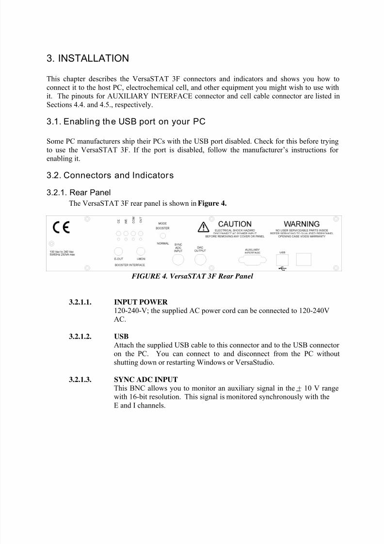
3.2.2. Front Panel
The VersaSTAT 3F front panel is shown in Figure 5.
FIGURE 5 VersaSTAT 3F front panel
3.2.2.1. CELL CABLE Connector The cell cable connector provides a means of
connecting a cell cable to the instrument. The cell cable is described in
more detail below.
3.2.2.1. INDICATORS
OVERLOAD: This LED lights if the working electrode current
exceeds 2x the full-scale current range.
POWER: This indicator lights when the VersaSTAT 3F is
powered on.

8/11/2019 V3F Manual
http://slidepdf.com/reader/full/v3f-manual 17/33
3.3. Connect ing to the PC and Cell
This section gives instructions on connecting the VersaSTAT 3F to the host PC and to
electrochemical cell and other equipment.
WARNING: For operator and equipment safety, power to all instruments should be off
when connecting or disconnecting cables.
3.3.1. Connecting to the PC
The VersaSTAT 3F is shipped with a standard USB cable. Connect it between the rear-panel
USB connector and a USB port on the PC. As noted above, it is not necessary to shut down andrestart Windows or VersaStudio.
3.3.1.1. Installing the USB Driver
The first time the VersaSTAT 3F is connected to the host PC and powered
on, Windows® should display a “Found New Hardware” message, and
request driver installation. Upon this request, insert the VersaStudio CDinto the CD-ROM drive, and select “Automatic” to install the ezusb.sys
driver.
3.3.2. Connecting the Cell
To connect the cell cable (part no. 223945) to the VersaSTAT 3F:
1. Make sure the POWER switch is off.
2. Match and attach the D connector side of the Cell cable to the front of the VersaSTAT3F, and secure the screws on either side.
3. After cell cable is connected to front panel, power the unit on and let it boot fully(approximately 1 min to boot up) before connecting a cell to the leads of the cell cable.
CAUTION: Having a cell connected at power-on or at power-off should be
avoided to prevent any voltage or current spikes from reaching the cell, or in the
case of energy storage devices (such as batteries, capacitors, or fuel cells),
preventing spikes from discharging back into the VersaSTAT 3F and causing
damage to the instrument.
8/11/2019 V3F Manual
http://slidepdf.com/reader/full/v3f-manual 18/33
4. The opposite end of cell cable is color-coded at the tip as follows:
• Green – Working (WE) electrode lead. This lead connects to the electrode of interest
at which the desired reactions will occur. The current (I) is measured through theWE.
• Red – Counter (CE) electrode lead. This lead connects to the electrode opposite the
WE and controls the power output of the VersaSTAT 3F.
• Gray – Sense (SE) electrode lead. This usually connects to the working electrode (the
combination often referred to as the working-sense), and is a component of the
differential amplifier that measures/controls the voltage between itself and the
reference electrode.
•
White – Reference (RE) electrode lead. This connects to the reference electrode, acomponent of the differential amplifier that measures/controls the voltage between
itself and the sense electrode.
• Black – Ground lead. The use of the ground lead depends on the application, but it isnot ordinarily used in most experiments. It can be used to supply a ground point to a
Faraday shield for the experimental cell, and is used in some open circuit experimentsto form a zero-resistance ammeter (ZRA).

8/11/2019 V3F Manual
http://slidepdf.com/reader/full/v3f-manual 19/33
5. The following descriptions and figures explain how to connect a two-, three-, or four-
terminal electrochemical cell to the terminals of the VersaSTAT 3F cell cable.
a) Batteries, capacitors, resistors, fuel cells, and some sensors are generally connected
using a two-terminal connection (Figure 6). The connectors for the cable leads are
designed to allow easy interconnection of the working/sense and reference/counterleads. Note: If your cell has low impedance (battery) and/or your experiment
generates currents in excess of 100mA, do not connect the leads into one another for a
two-terminal connection. Instead, connect the leads independent of one another totheir proper terminal at the cell to prevent voltage offsets that can result from
milliohms of contact resistance in a “piggy-back” connection as shown below.
Figure 6. Two-Electrode Connection
b) General aqueous electrochemistry, corrosion experiments, and most EISexperiments are connected using a three-terminal connection (Figure 7). The voltageat the working-sense is controlled relative to a stable reference electrode positioned in
close proximity to the working electrode.
Figure 7. Three-Electrode Connection

8/11/2019 V3F Manual
http://slidepdf.com/reader/full/v3f-manual 20/33
c) There are some applications for which a four-terminal (Figure 8) connection isrequired. In this case, the sense electrode serves as a second reference electrode,
useful for controlling the potential between the reference and sense (for instance, in
controlling the potential across a membrane in a H-cell setup).
Note: Running experiments in this mode requires that the Electrometer Mode
setting in the software be set to Differential for the correct potential to be
applied and read.
Figure 8. Four-Electrode Connection
CAUTION: Take care that the leads do not accidentally short together. Because the blackground lead is often unused, it tends to be overlooked and is more likely to
accidentally short together with another lead.
6. The polarity of the potential at the counter electrode will be opposite the “applied
potential”. This is necessary to establish the correct polarity relationship at the workingelectrode versus the reference electrode.
7. After all other connections to the VersaSTAT 3F are made, experiments can be set up and
performed.
3.4. Floating Operation
The VersaSTAT 3F was designed to operate in either a “normal” mode or a “floating” mode.
The floating mode provides the capability to operate with cells where one of the electrodes or the
8/11/2019 V3F Manual
http://slidepdf.com/reader/full/v3f-manual 21/33
cell itself is at earth ground. Examples of earth grounded cells include autoclaves, strain
apparatus, storage tanks and pipelines, and additional electrodes connected to a separate potentiostat that is not floating.
In floating mode, the internal ground of the VersaSTAT 3F (as well as the cell leads and external
connections at the rear panel) is allowed to float with respect to earth ground which allows it tooperate with these grounded cells.
NOTE: Instrument performance, particularly with regards to current and voltage noise, can besubstantially degraded when operating in float mode on grounded cells, the level of degradation
depending on the technique and the impedance between the electrodes and ground. Therefore
specifications listed in Section 4 apply only to isolated cells with the VersaSTAT 3F set tonormal mode.
The following section gives instructions on setting the VersaSTAT 3F to the floating mode.
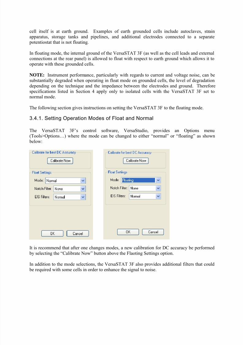
3.4.1. Setting Operation Modes of Float and Normal
The VersaSTAT 3F’s control software, VersaStudio, provides an Options menu(Tools>Options…) where the mode can be changed to either “normal” or “floating” as shown
below:
It is recommend that after one changes modes, a new calibration for DC accuracy be performed
by selecting the “Calibrate Now” button above the Flaoting Settings option.
In addition to the mode selections, the VersaSTAT 3F also provides additional filters that could
be required with some cells in order to enhance the signal to noise.
8/11/2019 V3F Manual
http://slidepdf.com/reader/full/v3f-manual 22/33
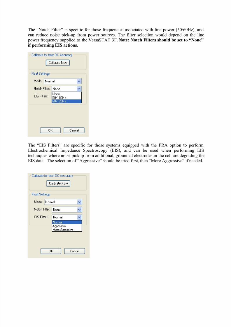
The “Notch Filter” is specific for those frequencies associated with line power (50/60Hz), and
can reduce noise pick-up from power sources. The filter selection would depend on the line power frequency supplied to the VersaSTAT 3F. Note: Notch Filters should be set to “None”
if performing EIS actions.
The “EIS Filters” are specific for those systems equipped with the FRA option to performElectrochemical Impedance Spectroscopy (EIS), and can be used when performing EIS
techniques where noise pickup from additional, grounded electrodes in the cell are degrading the
EIS data. The selection of “Aggressive” should be tried first, then “More Aggressive” if needed.
8/11/2019 V3F Manual
http://slidepdf.com/reader/full/v3f-manual 23/33
4. SPECIFICATIONS AND PINOUTS
4.1. Electronic Specifications
4.1.1 System Performance
• Minimum Time Base: 10 μs
• Minimum Potential Step: 1 uV
• Noise and Ripple < 50 μV rms typical
• Minimum Current Range: 4nA
• Minimum Current Resolution 6pA dc, 120fA ac
4.1.2. Power Amplifier
Compliance Voltage + 12 V
Maximum Current: + 650mA (+/-2A with 2A Option)
Rise Time: < 350 ns (no load)
4.1.3. Voltage Control
Applied Voltage Range + 10 V maximum
Applied Voltage Resolution + 10 mV = 300 nV
+ 100 mV = 3 uV, + 1 V = 30 uV, + 10 V = 300 uVApplied Voltage Accuracy + 0.2% of value + 2mV
Maximum Scan Rate 5000V/s Staircase Voltammetry (50mV step)
Maximum Scan Range/Resolution + 10 V / 300 uV
4.1.4. Current ControlApplied Current Range + full scale per range
Applied Current Resolution + 1/32,000 x full scaleApplied Current Accuracy + 0.2% of range , + 0.2% of reading
Maximum Current Range/Resolution + 1 A /100 uA
Minimum Current Range/Resolution + 4 nA / 120fA
4.1.5. Differential Electrometer
Input Bias Current < 5 pA at 25oC
Maximum Voltage Range + 10 V maximum
Input Voltage Differential + 10 V
Bandwidth -3 dB @ > 10 MHzCommon Mode Rejection 60 dB at 100 kHz
Input Impedance > 1012
Ω in parallel with < 5 pF

8/11/2019 V3F Manual
http://slidepdf.com/reader/full/v3f-manual 24/33
4.1.6. Voltage Measurement
Voltage Range + 10 V maximumMinimum Voltage Resolution + 6 uV
Voltage Accuracy + 0.2% reading, + 2 mV
4.1.7. Current Measurement
Ranges 10 decades, 2A to 4 nA
Accuracy (dc)
• 20 μA to 200 mA < 0.2% full scale
• 200 nA and 2μA ranges < 0.5% + 1nA full scale
• 4nA and 20nA ranges, <5% + 50 pA
Frequency Response (small signal)
• 20 mA Range -3 dB at > 1 MHz, 1K source impedance
• 20 μA Range -3 dB at > 100 kHz, 100K source impedance
4.1.8. iR Compensation
Positive Feedback Range: 50 MΩ to 5 Ω depending on current range
Dynamic iR : 5s/pt rate limit (limited to Corrosion techniques)
4.1.8. Potential/Current Control
Digital/Analog Converters (DACs)
Bias DAC
• Resolution 16 bits
•
Range (potentiostat) + 10V• Range (galvanostat) + 100% of full-scale current
Modulation DAC
• Resolution 16 bits
• Range (potentiostat) + 10V
• Range (galvanostat) + 100%
4.1.10. Impedance Specifications (if impedance opt ion available)
Frequency Range 10 μHz – 1 MHz
Maximum AC Voltage Amplitude 1000mV RMS
Minimum AC Voltage Amplitude 0.1mV RMS

8/11/2019 V3F Manual
http://slidepdf.com/reader/full/v3f-manual 25/33
4.2. Physical and Power Specifications
Computer Interface Universal Serial Bus (USB)
Weight 4.5 kg (10 lbs)
Dimensions 42.1 cm W x 38.7 cm D x 8.9 cm H (16.25 in x 15.25 in x 3.5 in )
Power Requirements
• 90-250 V AC, 50-60 Hz
4.3. Standard Environmental Conditions
This equipment is designed to meet or exceed the requirements of the following
standards:
• LVD: EN61010-1:1993, Amendment 2
•
EMC: EN61326: 1998 Emissions
• EN55011:1991, Group 1, Class A
Immunity:
•
IEC 61000-4-2:1995, ESD
• IEC 61000-4-3:1995, EM field
• IEC 61000-4-4:1995, Burst
• IEC 61000-4-5:1995, Surge
• IEC 61000-4-6:1995, Conducted RF
Operating Temperature: 10
o
C to 50
o
CHumidity: maximum 80% non-condensing

8/11/2019 V3F Manual
http://slidepdf.com/reader/full/v3f-manual 26/33
4.4. AUXILIARY INTERFACE Pinouts
Pin Signal Function
1 Ground
2 TRIG IN Using the VersaStudio software, an experiment can be held,waiting on this TTL trigger input signal to be read.
3 DISPENSE When using the VersaSTAT 3F with a Model 303 or 303A Static
Mercury Drop Electrode (SMDE) via a Model 507 interface,this signal causes the electrode to perform a
DISLODGE/DISPENSE operation on command from the host
PC.
4 TRIG OUT A TTL trigger output is provided on this line with the VersaStudiosoftware
5 BIT O IN Not used.
6 - Not used.
7 BIT O OUT Not used.8 PURGE When using a Model 303 or 303A SMDE via a Model 507
Interface, this signal controls the electrode’s PURGE functionin response to commands from the host PC .
9 STIR This signal controls the Model 303 or 303A’s STIR function in
response to commands from an external computer. It is assumed
that the electrode is being used with a Model 305 stirrer.
4.5. Cell Cable Pinouts
Pin Signal Function
A1 SENSE See section 3.3.2.A2 WORKING See section 3.3.2.
A3 COUNTER See section 3.3.2.
A4 REFERENCE See section 3.3.2.1 GROUND See section 3.3.2.
9 GROUND See section 3.3.2.
2-8 RESERVED Reserved for future options
10-17 RESERVED Reserved for future options

8/11/2019 V3F Manual
http://slidepdf.com/reader/full/v3f-manual 27/33
5. AVAILABLE OPTIONSThe factory installed options available for the VersaSTAT 3F are as follows:
1) 2A high current option
2) FRA Option for Electrochemical Impedance Spectroscopy measurements
3)
Advanced Auxiliary Interface4) Power Boosters, either 8A, 10A, or 20A.
5.1 2A High Current Option
The 2A High Current Option for the VersaSTAT 3F expands the upper applied and measured
current from the base 650mA up to 2A. This option is built into the base unit, so it must be
purchased at the same time along with the base unit, or at a later time by returning the base unitto a qualified Princeton Applied Research Service Center for installation and calibration.
5.2 FRA Option
The FRA Option provides the hardware necessary to perform the ac-based techniques of
Potentiostatic Electrochemical Impedance Spectroscopy (PEIS) and Galvanostatic
Electrochemical Impedance Spectroscopy (GEIS). This option is built into the base unit, so itmust be purchased at the same time along with the base unit, or at a later time by returning the
base unit to a qualified Princeton Applied Research Service Center for installation and
calibration.
5.3 Advanced Auxiliary Interface Option
The Advanced Auxiliary Interface (AAI) Option allows for an additional four (4) A/D inputs for
the VersaStudio software to acquire along with data recorded directly from the VersaSTAT 3F.
The AAI is an external unit that plugs directly into the same PC as that interfaced by the
VersaSTAT 3F into an available USB port. The VersaStudio auto-detects the AAI, and collectsdata on the additional four A/D inputs along with data directly from the V3 hardware (E, I, AUX,
etc.).
The AAI is a +/-10V DC input, 12-bit unit (+/-5mV resolution) system, and is recommended forwhen several variables need to be colleted concurrently with the electrochemical data, such a pH,
temperature, etc.
Although an external unit, the AAI requires that it must be purchased at the same time along with
the base unit, or at a later time by returning the base unit to a qualified Princeton Applied
Research Service Center for installation and calibration of necessary components internal to theV3 hardware.

8/11/2019 V3F Manual
http://slidepdf.com/reader/full/v3f-manual 28/33
5.4 Power Booster Options
The Power Booster Options available for the VersaSTAT 3F include a 20V/10A, 20V/20A, and
50V/8A.
Note: The voltage component for the boosters is compliance voltage increase, not referencevoltage increase. The maximum reference voltage remains at +/-10V.
Each power booster includes an external power supply interfaced to additional internal circuitryof the VersaSTAT 3F system via the rear panel. Once connected, the V3 can be operated in
either boosted mode or normal mode depending on a switch setting at the rear panel, as well as
some cell cable changes. When set to “Booster” mode and interfaced correctly to the external power supply, currents up to the maximum for each option can be applied or measured. The
VersaStudio software auto-detects the booster mode, and automatically sets the parameters
needed to operate correctly in that mode.
Note: In boosted mode, the system is required to stay on a single current range, and is limited in
this mode to current measurements at a resolution of 16 bits for the boosted range.
This option has components that are built into the base unit, so it must be purchased at the same
time along with the base unit, or at a later time by returning the base unit to a qualified Princeton
Applied Research Service Center for installation and calibration.
Refer to Appendix 1 in this hardware section for power booster setup and connections.

8/11/2019 V3F Manual
http://slidepdf.com/reader/full/v3f-manual 29/33
6. Advanced Measurement Technology, Inc. a/k/a Princeton Applied Research, a subsidiary of AMETEK®, Inc.
WARRANTYPrinceton Applied Research* warrants each instrument of its own manufacture to be free of defects in material andworkmanship. Obligations under this Warranty shall be limited to replacing, repairing or giving credit for the purchase price, atour option, of any instrument returned, shipment prepaid, to our Service Department for that purpose within ONE year of
delivery to the original purchaser, provided prior authorization for such return has been given by an authorized representative ofPrinceton Applied Research.
This Warranty shall not apply to any instrument, which our inspection shall disclose to our satisfaction, to have become
defective or unworkable due to abuse, mishandling, misuse, accident, alteration, negligence, improper installation, or othercauses beyond our control. This Warranty shall not apply to any instrument or component not manufactured by PrincetonApplied Research. When products manufactured by others are included in Princeton Applied Research equipment, the originalmanufacturer's warranty is extended to Princeton Applied Research customers.
Princeton Applied Research reserves the right to make changes in design at any time without incurring any obligation to installsame on units previously purchased.
THERE ARE NO WARRANTIES THAT EXTEND BEYOND THE DESCRIPTION ON THE FACE HEREOF. THISWARRANTY IS IN LIEU OF, AND EXCLUDES ANY AND ALL OTHER WARRANTIES OR REPRESENTATIONS,
EXPRESSED, IMPLIED OR STATUTORY, INCLUDING MERCHANTABILITY AND FITNESS, AS WELL AS ANY ANDALL OTHER OBLIGATIONS OR LIABILITIES OF PRINCETON APPLIED RESEARCH, INCLUDING, BUT NOTLIMITED TO, SPECIAL OR CONSEQUENTIAL DAMAGES. NO PERSON, FIRM OR CORPORATION IS AUTHORIZEDTO ASSUME FOR PRINCETON APPLIED RESEARCH ANY ADDITIONAL OBLIGATION OR LIABILITY NOT
EXPRESSLY PROVIDED FOR HEREIN EXCEPT IN WRITING DULY EXECUTED BY AN OFFICER OF PRINCETONAPPLIED RESEARCH.
SHOULD YOUR EQUIPMENT REQUIRE SERVICE
A. Contact the Customer Service Department (865-482-4411) or your local representative to discuss the problem. In manycases it will be possible to expedite servicing by localizing the problem.
B. If it is necessary to send any equipment back for service, we need the following information.
1. Model number and serial number.2. Your name (instrument user).3. Your address.
4. Address to which the instrument should be returned.5. Your telephone number and extension.6. Symptoms (in detail, including control settings).
7. Your purchase order number for repair charges (does not apply to repairs in warranty).8. Shipping instructions (if you wish to authorize shipment by any method other than normal surface transportation).
C. U.S. CUSTOMERS — Ship the equipment being returned to:
Advanced Measurement Technology, Inc. PHONE: 865-482-4411801 S. Illinois Avenue FAX: 865-483-2133
Oak Ridge, TN 37831ATTN: Customer Service
D. CUSTOMERS OUTSIDE OF U.S.A. — To avoid delay in customs clearance of equipment being returned, please contact the
factory or the nearest factory distributor for complete shipping information.
Copyright © 2003, Advanced Measurement Technology, Inc. All rights reserved.
*Princeton Applied Research is a registered trademark of Advanced Measurement Technology, Inc. All other trademarks used herein are the
property of their respective owners.

8/11/2019 V3F Manual
http://slidepdf.com/reader/full/v3f-manual 30/33
Appendix 1.
VersaSTAT 3F External Power Booster Connections
General
There are three External Power Booster options for the VersaSTAT 3F (all power ratings are
nominal as determined by bipolar power supply):
• The 8A/VERSASTAT3 provides ± 8 amps at ± 50 volts.
• The 10A/VERSASTAT3 provides ± 10 amps at ± 20 volts.
• The 20A/VERSASTAT3 provides ± 20 amps at ± 20 volts.
This add-on option consists of a specially configured bipolar power supply from KEPCO®, Inc.,an internal (inside VersaSTAT 3F chassis) Princeton Applied Research Power Booster Interface,
and cabling.
NOTE: The VersaSTAT 3F is factory configured and calibrated to operate with the bipolar
power supply purchased with the option. Using a different power supply could damage your
system. Before using a different KEPCO with your VersaSTAT 3F with booster option, contact
your local Princeton Applied Research representative or service center
All experiments are computer-controlled via the VersaStudio software which correctly scales thecurrent entry and measurement. No correction factor is required as with some other power
booster options.
The VersaSTAT 3F functions on a fixed current range of 2mA when operating in “Booster
Mode” with the KEPCO power supply. The interface board scales the current signals from theKEPCO to allow current measurements to ± 20 amps.
The system frequency response has been modified in booster mode to provide stability for thecomplete closed-loop response for electrochemical cells with a very high capacitance and very
low resistance.
Connections and settings are identical among the three external power booster options.
The power booster interface operates in power-boosted or normal modes --- a simple cable
connection and flip of a switch convert between the two modes. This section discusses the boosted mode only.
8/11/2019 V3F Manual
http://slidepdf.com/reader/full/v3f-manual 31/33
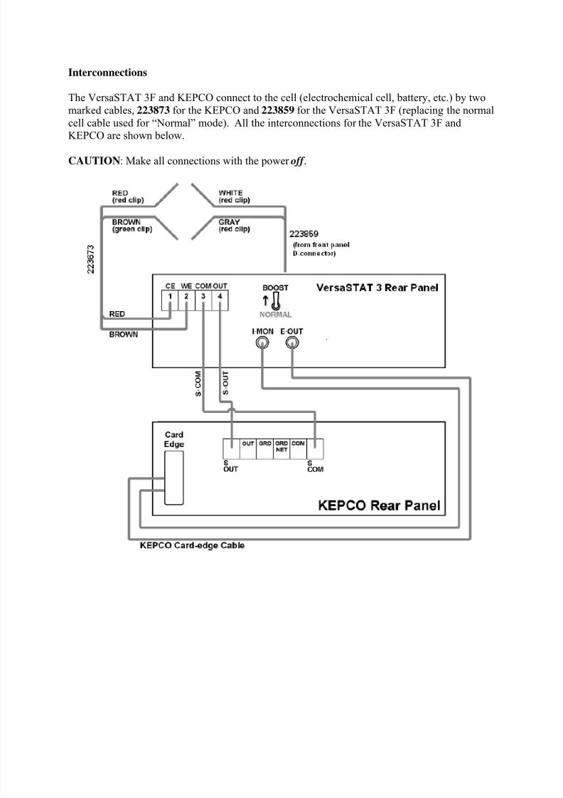
Interconnections
The VersaSTAT 3F and KEPCO connect to the cell (electrochemical cell, battery, etc.) by two
marked cables, 223873 for the KEPCO and 223859 for the VersaSTAT 3F (replacing the normal
cell cable used for “Normal” mode). All the interconnections for the VersaSTAT 3F and
KEPCO are shown below.
CAUTION: Make all connections with the power off .

8/11/2019 V3F Manual
http://slidepdf.com/reader/full/v3f-manual 32/33
KEPCO Front-Panel Setup
• The MODE switch on the front panel of the KEPCO should be set to Voltage mode (left
position).
• The Voltage CONTROL switch (red toggle on left side) should be in the OFF (down)
position.
• The Current CONTROL switch (red toggle on right side) should be in the OFF (down)
position.
• The SENSE/COMMON (black banana jacks at bottom-center) should be inter-connected with a shorting bracket.
• The OUTPUT/SENSE (red banana jacks at bottom-center) should be inter-connected
with a shorting bracket.
External Cell Connection and Checkout
Use the cables 223859 and 223873 to connect the cell being tested.
DANGER: Dangerous and possibly lethal voltages may be present on the COUNTER lead. Never touch the leads while mains power is supplied to the KEPCO. For more information, see
the accompanying KEPCO manual.
8/11/2019 V3F Manual
http://slidepdf.com/reader/full/v3f-manual 33/33
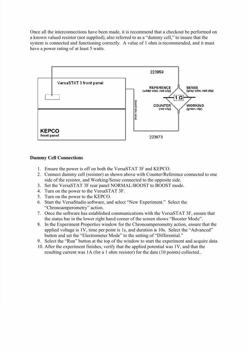
Once all the interconnections have been made, it is recommend that a checkout be performed on
a known valued resistor (not supplied), also referred to as a “dummy cell,” to insure that thesystem is connected and functioning correctly. A value of 1 ohm is recommended, and it must
have a power rating of at least 5 watts.
Dummy Cell Connections
1. Ensure the power is off on both the VersaSTAT 3F and KEPCO.
2. Connect dummy cell (resistor) as shown above with Counter/Reference connected to one
side of the resistor, and Working/Sense connected to the opposite side.
3.
Set the VersaSTAT 3F rear panel NORMAL/BOOST to BOOST mode.4. Turn on the power to the VersaSTAT 3F.
5. Turn on the power to the KEPCO.6. Start the VersaStudio software, and select “New Experiment.” Select the
“Chronoamperometry” action.
7. Once the software has established communications with the VersaSTAT 3F, ensure thatthe status bar in the lower right hand corner of the screen shows “Booster Mode”.
8. In the Experiment Properties window for the Chronoamperometry action, ensure that the
applied voltage is 1V, time per point is 1s, and duration is 10s. Select the “Advanced” button and set the “Electrometer Mode” to the setting of “Differential.”
9. Select the “Run” button at the top of the window to start the experiment and acquire data.
10.
After the experiment finishes, verify that the applied potential was 1V, and that theresulting current was 1A (for a 1 ohm resistor) for the data (10 points) collected..