v200 external option - automated controls · standard isa s7.3-81. caution: beware of moving parts...
TRANSCRIPT
V200 POSITIONERwww.vacaccessories.com/v200
1 V200 External options IOM r2
Valve Accessories & Controls
Installation,Operation andMaintenanceInstruction
V200 EXTERNAL OPTION

V200 POSITIONERwww.vacaccessories.com/v200
3 V200 External options IOM r2
1 INTRODUCTION ................................................................................. 4
1.1 Air quality recommendations .................................................. 4
1.2 Safety Instructions ................................................................ 4
2 INSTALLATION .................................................................................. 5
2.1 Installing external IP converter on V200P .............................. 5
2.2 Installing external IP converter on V200E .............................. 6
2.3 Main supply filter for IP converter .......................................... 73 SPARE PARTS .................................................................................. 8
3.1 Exploded drawing external options ......................................... 83.2 Spare parts list external options ............................................ 9
4 SPECIFICATIONS ............................................................................. 104.1 Specifications external options .............................................. 10
5 DIMENSIONS .................................................................................... 117.1 V200 E 0-10V ........................................................................ 117.2 V200 EX and V200 EX-GA .................................................... 127.3 V200 FF................................................................................. 13
CONTENTS
V200 POSITIONERwww.vacaccessories.com/v200
V200 External options IOM r24
1.1 Air quality recommendations
Poor air quality is one of the main causes ofpremature functional problems with pneumaticand electropneumatic equipment. The pilotvalve and IP converter are precision instru-ments, and are therefore the most sensitiveparts of the positioner.
a) Water in the supply air is a natural occur-rence. This happens when air is compressed.The compression heats the air and the naturaldegree of water in the air can remain as mois-ture. When the air cools in pipes etc.the moisture condenses and becomes liquidwater. Large quantities can build and some-times flood small water separators. This ex-cess water will eventually reach the controlvalve and positioner. This can cause corrosiondamage to the IP converter, causing theunit to malfunction.
We strongly recommend the use of waterseparators with adequate capacity. Coalesingfilters from a reputable manufacturer is aninexpensive way to help prevent unit malfunc-tions or failures, and add life to the product.These filters remove particles and moisturefrom air lines.
b) Oil in the supply air usually is from the maincompressor. Oil can clog the small nozzles anddisturb the flapper in the IP converter. It canalso cause the spool to “drag” within the pilotvalve. The result is poor control or in the worstcase, failure.
c) Particles in the air usually occur because ofcorrosion. Dirt and particles can block thesmall nozzles of the IP converter.They can also cause the pilot valve to mal-function. The unit may completely fail.
To ensure normal operational safety with VACpositioner products, we recommend that awater separator and a <80 micrometer filter aremounted as close to the product as possible.If large amounts of oil are present an oil sepa-rator should be installed as well.
To further increase operational safety, werecommend that the working air is clean, dryand free of moisture, water, oil, particles andother contaminants, in accordance with the ISAStandard ISA S7.3-81.
CAUTION: Beware of moving partswhen positioner is operated!
CAUTION: Beware of parts withlive voltage!A voltage, which is normally notdangerous, is supplied to thepositioner.Avoid touching live parts and barewires as well as short circuiting liveparts and the housing.
CAUTION: Do not dismantle apressurized positioner!Dismantling a pressurized positionerwill result in uncontrolled pressurerelease. Always isolate the relevantpart of the pipeline. Release the pres-sure from the positioner and the pip-ing. Failure to do this may result indamage or personal injury.
CAUTION: Do not exceed thepositioner performance limitations!Exceeding the limitations marked onthe positioner may cause damage tothe positioner, actuator and valve.Damage or personal injury may result.
1.2 Safety Instructions
1 INTRODUCTION
V200 POSITIONERwww.vacaccessories.com/v200
5 V200 External options IOM r2
2 INSTALLATION
1
3
2
4
5
1
2
6
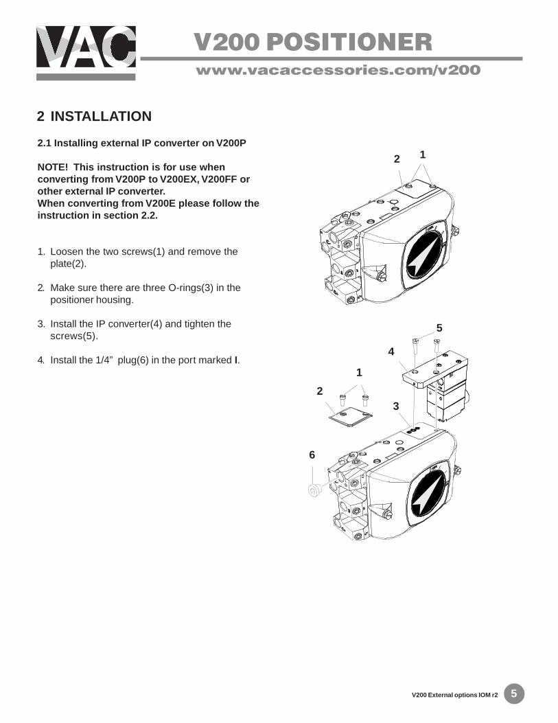
2.1 Installing external IP converter on V200P
NOTE! This instruction is for use whenconverting from V200P to V200EX, V200FF orother external IP converter.When converting from V200E please follow theinstruction in section 2.2.
1. Loosen the two screws(1) and remove theplate(2).
2. Make sure there are three O-rings(3) in thepositioner housing.
3. Install the IP converter(4) and tighten thescrews(5).
4. Install the 1/4” plug(6) in the port marked I.
V200 POSITIONERwww.vacaccessories.com/v200
V200 External options IOM r26
4
2
1
5
3
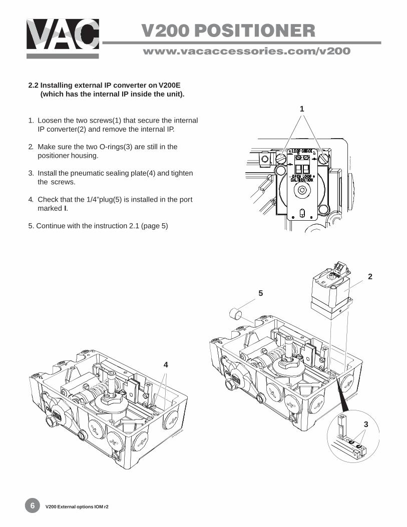
2.2 Installing external IP converter on V200E (which has the internal IP inside the unit).
1. Loosen the two screws(1) that secure the internalIP converter(2) and remove the internal IP.
2. Make sure the two O-rings(3) are still in thepositioner housing.
3. Install the pneumatic sealing plate(4) and tightenthe screws.
4. Check that the 1/4”plug(5) is installed in the portmarked I.
5. Continue with the instruction 2.1 (page 5)
V200 POSITIONERwww.vacaccessories.com/v200
7 V200 External options IOM r2
1
2
3 4
2
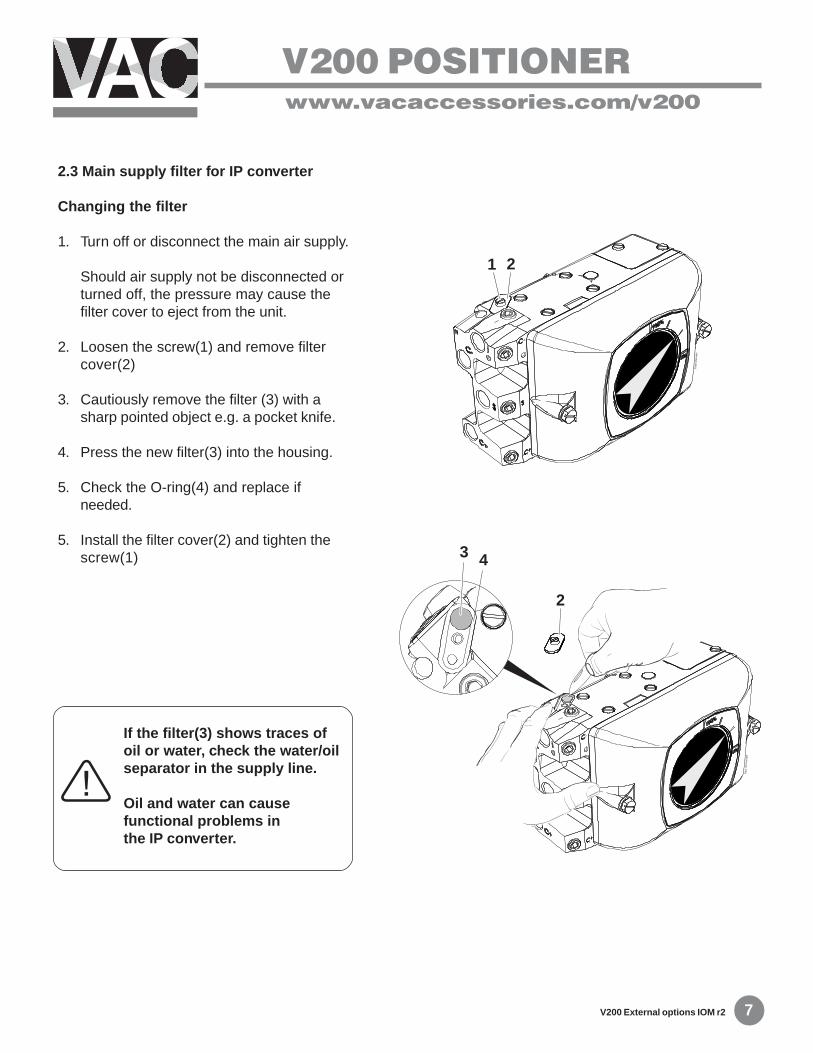
2.3 Main supply filter for IP converter
Changing the filter
1. Turn off or disconnect the main air supply.
Should air supply not be disconnected orturned off, the pressure may cause thefilter cover to eject from the unit.
2. Loosen the screw(1) and remove filtercover(2)
3. Cautiously remove the filter (3) with asharp pointed object e.g. a pocket knife.
4. Press the new filter(3) into the housing.
5. Check the O-ring(4) and replace ifneeded.
5. Install the filter cover(2) and tighten thescrew(1)
If the filter(3) shows traces ofoil or water, check the water/oilseparator in the supply line.
Oil and water can causefunctional problems inthe IP converter.

V200 POSITIONERwww.vacaccessories.com/v200
V200 External options IOM r28
3.1 Exploded drawing external options
3 SPARE PARTS
V200 POSITIONERwww.vacaccessories.com/v200
9 V200 External options IOM r2
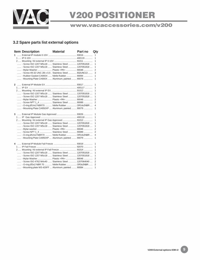
3.2 Spare parts list external options
Item Description Material Part no Qty1 ...... External IP module 0-10V ............................................ 93016 .............. 1
1 ..... IP 0-10V ....................................................................... 400119 ............ 12 ..... Mounting Kit external IP 0-10V ................................... 91011 .............. 1...... - Screw ISO 1207 M5x18 ...... Stainless Steel ............. 1207051818 .... 1...... - Screw ISO 1207 M5x18 ...... Stainless Steel ............. 1207051818 .... 1...... - Mylar Washer ...................... Plastic <PA> ................. 90048 .............. 2...... - Screw #8-32 UNC 2B x 0,5 . Stainless Steel ............. 832UNC13 ....... 3...... - Rubber Gasket CA900X ...... Nitrile Rubber ................ 90094 .............. 1...... - Mounting Plate CA900X ...... Aluminum, painted ........ 90078 .............. 1
2 ...... External IP Module EX ................................................. 93017 .............. 11 ..... IP EX ........................................................................... 400117 ............ 12 ..... Mounting Kit external IP EX ........................................ 91012 .............. 1...... - Screw ISO 1207 M5x18 ...... Stainless Steel ............. 1207051818 .... 1...... - Screw ISO 1207 M5x18 ...... Stainless Steel ............. 1207051818 .... 1...... - Mylar Washer ...................... Plastic <PA> ................. 90048 .............. 2...... - Screw NPT 1_4 ................... Stainless Steel ............. 90089 .............. 2...... - O-ring Ø14x2 NBR70 .......... Nitrile Rubber ................ OR14x2NBR .... 4...... - Mounting Plate CA950XP .... Aluminum, painted ........ 90079 .............. 1
3 ...... External IP Module Gas Approved ............................... 93026 .............. 11 ..... IP Gas Approved ........................................................ 400118 ............ 12 ..... Mounting Kit external IP Gas Approved ...................... 91012 .............. 1...... - Screw ISO 1207 M5x18 ...... Stainless Steel ............. 1207051818 .... 1...... - Screw ISO 1207 M5x18 ...... Stainless Steel ............. 1207051818 .... 1...... - Mylar washer ....................... Plastic <PA> ................. 90048 .............. 2...... - Screw NPT 1_4 ................... Stainless Steel ............. 90089 .............. 2...... - O-ring Ø14x2 NBR70 .......... Nitrile Rubber ................ OR14x2NBR .... 4...... - Mounting Plate CA950XP .... Aluminum, painted ........ 90079 .............. 1
4 ...... External IP Module Fail Freeze .................................... 93019 .............. 11 ..... IP Fail Freeze ............................................................... 92070 .............. 12 ..... Mounting Kit external IP Fail Freeze ........................... 91014 .............. 1...... - Screw ISO 1207 M5x18 ...... Stainless Steel ............. 1207051818 .... 1...... - Screw ISO 1207 M5x18 ...... Stainless Steel ............. 1207051818 .... 1...... - Mylar Washer ...................... Plastic <PA> ................. 90048 .............. 2...... - Screw ISO 4762 M4x40 ...... Stainless Steel ............. 1207064040 .... 2...... - O-ring Ø3x2 NBR 70 ........... Nitrile Rubber ................ OR3x2NBR ...... 2...... - Mounting plate WS 420FF ... Aluminum, painted ........ 90084 .............. 1
V200 POSITIONERwww.vacaccessories.com/v200
V200 External options IOM r210
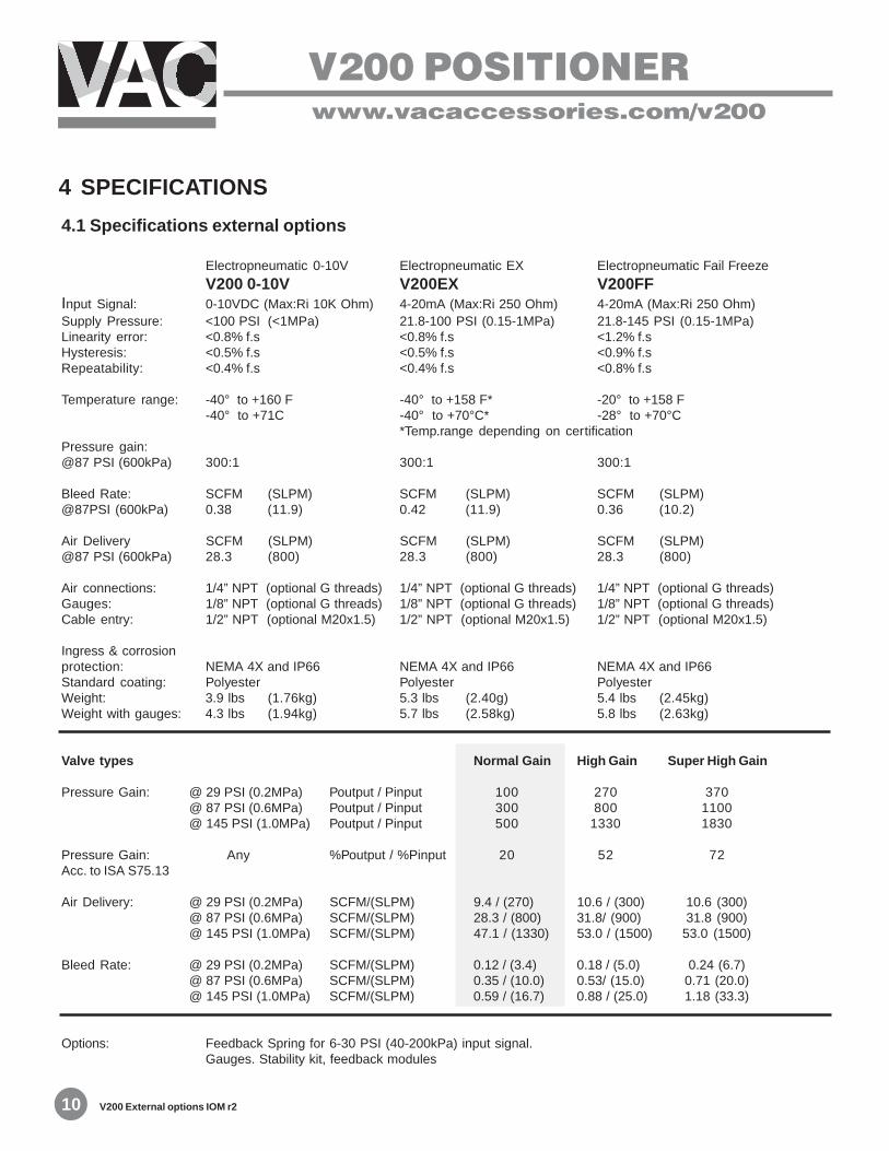
4.1 Specifications external options
Electropneumatic 0-10V Electropneumatic EX Electropneumatic Fail Freeze
V200 0-10V V200EX V200FFInput Signal: 0-10VDC (Max:Ri 10K Ohm) 4-20mA (Max:Ri 250 Ohm) 4-20mA (Max:Ri 250 Ohm)Supply Pressure: <100 PSI (<1MPa) 21.8-100 PSI (0.15-1MPa) 21.8-145 PSI (0.15-1MPa)Linearity error: <0.8% f.s <0.8% f.s <1.2% f.sHysteresis: <0.5% f.s <0.5% f.s <0.9% f.sRepeatability: <0.4% f.s <0.4% f.s <0.8% f.s
Temperature range: -40° to +160 F -40° to +158 F* -20° to +158 F-40° to +71C -40° to +70°C* -28° to +70°C
*Temp.range depending on certificationPressure gain:@87 PSI (600kPa) 300:1 300:1 300:1
Bleed Rate: SCFM (SLPM) SCFM (SLPM) SCFM (SLPM)@87PSI (600kPa) 0.38 (11.9) 0.42 (11.9) 0.36 (10.2)
Air Delivery SCFM (SLPM) SCFM (SLPM) SCFM (SLPM)@87 PSI (600kPa) 28.3 (800) 28.3 (800) 28.3 (800)
Air connections: 1/4” NPT (optional G threads) 1/4” NPT (optional G threads) 1/4” NPT (optional G threads)Gauges: 1/8” NPT (optional G threads) 1/8” NPT (optional G threads) 1/8” NPT (optional G threads)Cable entry: 1/2” NPT (optional M20x1.5) 1/2” NPT (optional M20x1.5) 1/2” NPT (optional M20x1.5)
Ingress & corrosionprotection: NEMA 4X and IP66 NEMA 4X and IP66 NEMA 4X and IP66Standard coating: Polyester Polyester PolyesterWeight: 3.9 lbs (1.76kg) 5.3 lbs (2.40g) 5.4 lbs (2.45kg)Weight with gauges: 4.3 lbs (1.94kg) 5.7 lbs (2.58kg) 5.8 lbs (2.63kg)
Valve types Normal Gain High Gain Super High Gain
Pressure Gain: @ 29 PSI (0.2MPa) Poutput / Pinput 100 270 370@ 87 PSI (0.6MPa) Poutput / Pinput 300 800 1100@ 145 PSI (1.0MPa) Poutput / Pinput 500 1330 1830
Pressure Gain: Any %Poutput / %Pinput 20 52 72Acc. to ISA S75.13
Air Delivery: @ 29 PSI (0.2MPa) SCFM/(SLPM) 9.4 / (270) 10.6 / (300) 10.6 (300)@ 87 PSI (0.6MPa) SCFM/(SLPM) 28.3 / (800) 31.8/ (900) 31.8 (900)@ 145 PSI (1.0MPa) SCFM/(SLPM) 47.1 / (1330) 53.0 / (1500) 53.0 (1500)
Bleed Rate: @ 29 PSI (0.2MPa) SCFM/(SLPM) 0.12 / (3.4) 0.18 / (5.0) 0.24 (6.7)@ 87 PSI (0.6MPa) SCFM/(SLPM) 0.35 / (10.0) 0.53/ (15.0) 0.71 (20.0)@ 145 PSI (1.0MPa) SCFM/(SLPM) 0.59 / (16.7) 0.88 / (25.0) 1.18 (33.3)
Options: Feedback Spring for 6-30 PSI (40-200kPa) input signal.Gauges. Stability kit, feedback modules
4 SPECIFICATIONS

V200 POSITIONERwww.vacaccessories.com/v200
11 V200 External options IOM r2
5.1 V200E 0/10V
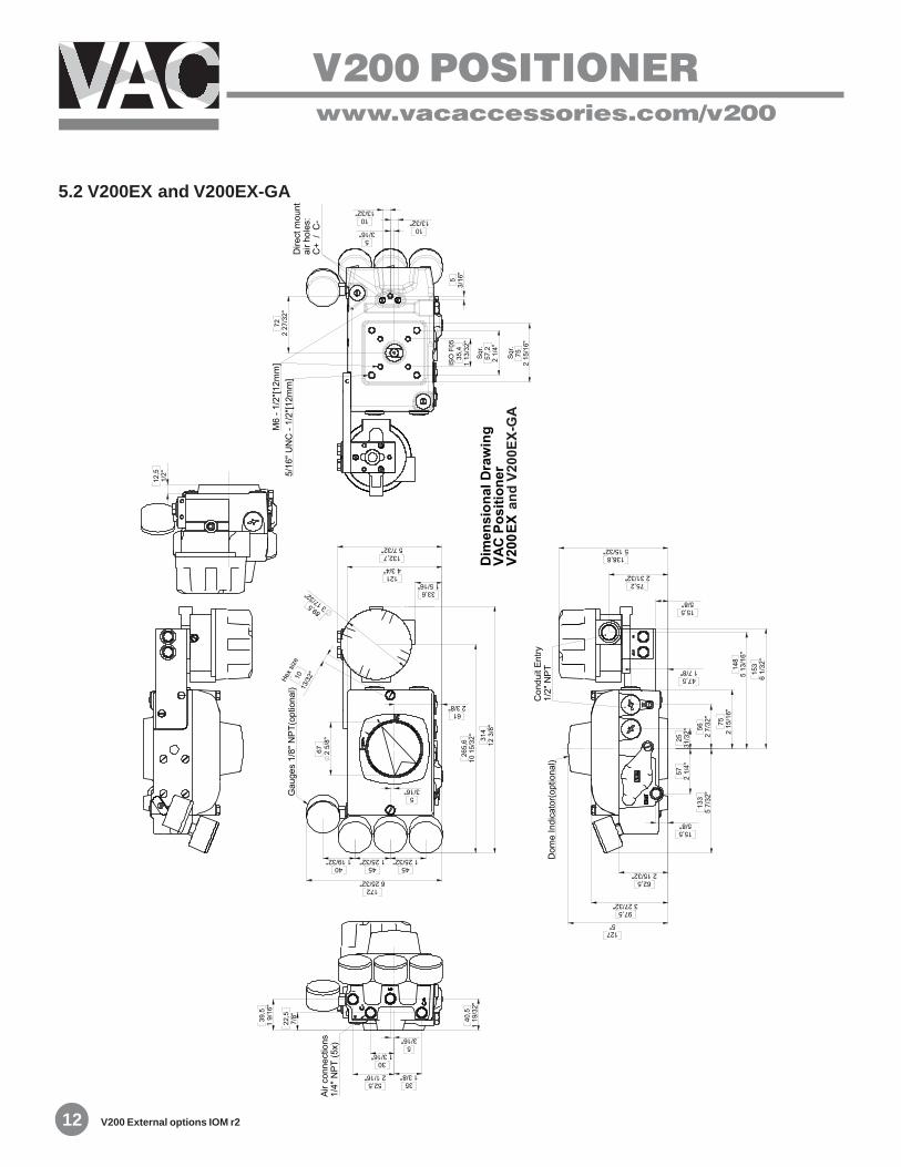
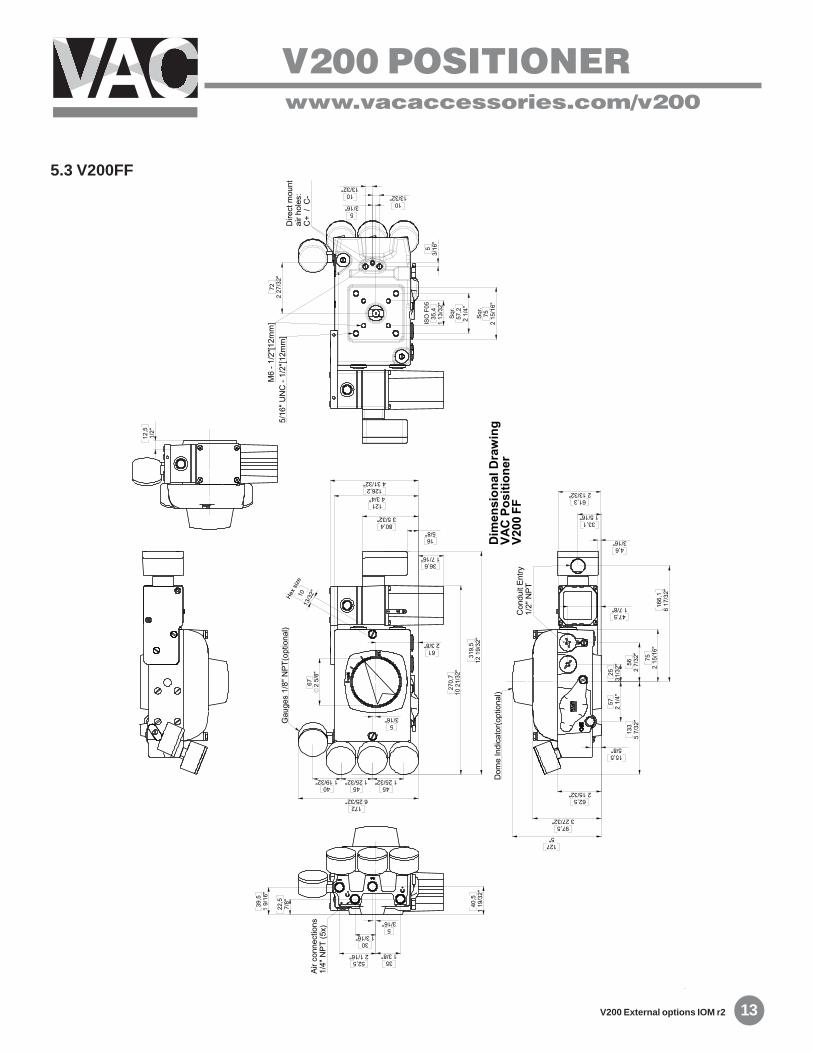
5 DIMENSIONS
V200 POSITIONERwww.vacaccessories.com/v200
V200 External options IOM r212
5.2 V200EX and V200EX-GA
V200 POSITIONERwww.vacaccessories.com/v200
13 V200 External options IOM r2
5.3 V200FF