v v e r r b m k - jaif.or.jp · pdf file• pressurised light water used as moderator ......
TRANSCRIPT

R. S. CTU Prague WNU SI 2010 1
Current reactor technology, part III:
V V E RR B M K
Radek Škoda
Czech Technical University Prague
WNU SI 2010
Christ Church, Oxford

R. S. CTU Prague WNU SI 2010 2
Overview1.Gen 1-2-3-4
2. Reactor technology: RBMK
3.Reactor technology: VVER
4.Which reactor is good then???

R. S. CTU Prague WNU SI 2010 3
For those who have not seen this graph yet :-)
R. S. CTU Prague WNU SI 2010 4
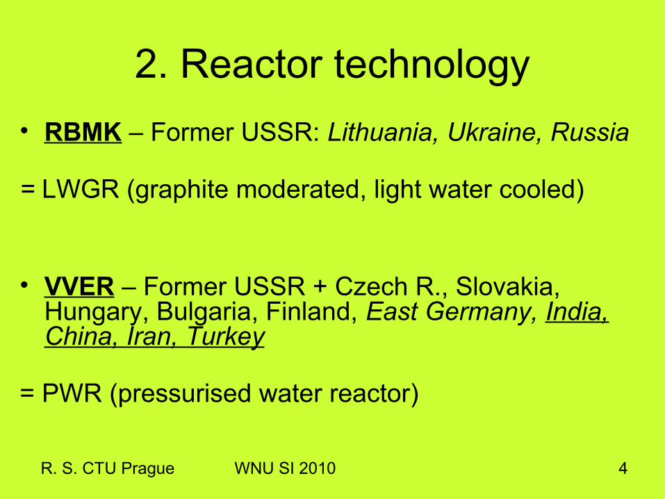
2. Reactor technology• RBMK – Former USSR: Lithuania, Ukraine, Russia = LWGR (graphite moderated, light water cooled)
• VVER – Former USSR + Czech R., Slovakia, Hungary, Bulgaria, Finland, East Germany, India, China, Iran, Turkey
= PWR (pressurised water reactor)

R. S. CTU Prague WNU SI 2010 5
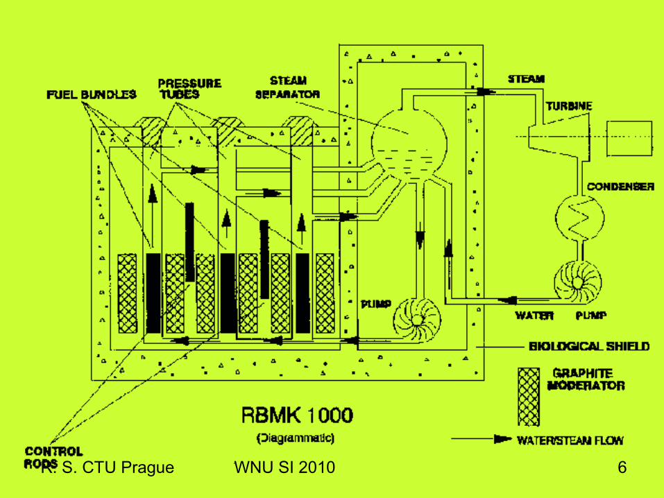
RBMK = containment? + void?Graphite moderator
Light water coolant
Boiling in channels
Low enrichment
Variable Pu vector
R. S. CTU Prague WNU SI 2010 6
R. S. CTU Prague WNU SI 2010 7
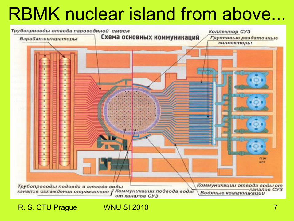
RBMK nuclear island from above...
R. S. CTU Prague WNU SI 2010 8
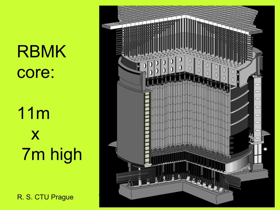
RBMKcore:
11m x 7m high

R. S. CTU Prague WNU SI 2010 9
Reactor hall

R. S. CTU Prague WNU SI 2010 10
Mk 1
R. S. CTU Prague WNU SI 2010 11
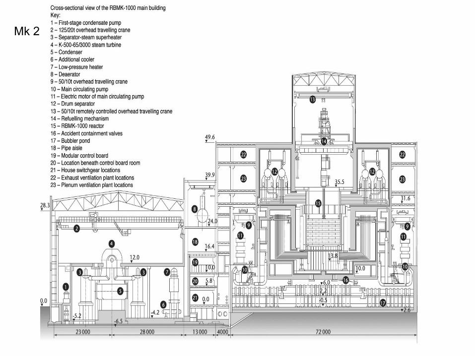
Mk 2

R. S. CTU Prague WNU SI 2010 12
RBMK Mk 2

R. S. CTU Prague WNU SI 2010 13
Key technical characteristics
Core parameters RBMK-1000
RBMK-1500
Power, MW:- Electric - Thermal
10003200
15004800
Number of fuel channels, pcs.
1693 1661
Coolant
Steam-water mixture
Steam-water mixture
Steam characteristics before the turbine: - pressure, MPa - Temperature ,°С
6,38 280
6,38 280
Coolant temperature:
- at the core inlet
270 270
- at the core outlet
284 284
Water flow through the reactor, t/h
37500 29020
FA characteristics
RBMK-1000 RBMK-1500
Max. power of the fuel channel with fuel assembly, MW
3 4,25
Service time, years
7 6
FA dimensions:- length, mm - diameter, mm
10014 79
10014 79
FA weight, kg
185 185
U-235 enrichment depending on design modification,%
2,6; 2,8 2,4; 2,6
Average fuel burn-up depending on enrichment, MW d/kg U
25,8 (2,6%)30 (2,8%)
20,5 (2,4%)26 (2,6%)
Max. fuel burn-up depending on enrichment, MW d/kg U
29,6 (2,6%)34,5 (2,8%)
23,5 (2,4%)30 (2,6%)
RBMK

R. S. CTU Prague WNU SI 2010 14
RBMK 1500 IGNALINA

R. S. CTU Prague WNU SI 2010 15
RBMK 1500 IGNALINA
More of this nice accent on: http://www.youtube.com/watch?v=5dZ4mD6gKjg

Now only 1 RBMK being built
R. S. CTU Prague WNU SI 2010
R. S. CTU Prague WNU SI 2010 17
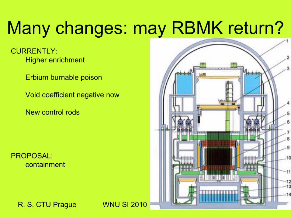
Many changes: may RBMK return?CURRENTLY:
Higher enrichment
Erbium burnable poison
Void coefficient negative now
New control rods
PROPOSAL:containment
CONTAINMENTs
D.I.Y.
R. S. CTU Prague WNU SI 2010

• Thermal nuclear reactors
• Pressurised Light Water used as moderator
• Pressurised Light Water used as coolant
• Steam generator used to produce steam
R. S. CTU Prague WNU SI 2010 19
3. VVER (WWER) reactors

R. S. CTU Prague WNU SI 2010 20
NPP Shippingport-1
68 MWe
USA Submarine
SSN-571Nautilus
PWR = submarine technology
Russian Submarine
NPP Novovoroněž-1
210 MWe
Remember: PWR in the world
R. S. CTU Prague WNU SI 2010 21
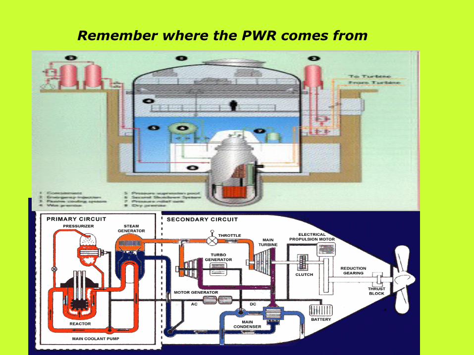
Remember where the PWR comes from

• First demoplants: PWR at Shippingport in USA: 1957 VVER-210 at USSR: 1964
• In USSR focused on RBMK reactors (LWGR) at that time, “eastern” PWR development initially in Eastern Germany !!
• 7 year technology gap
R. S. CTU Prague WNU SI 2010 22
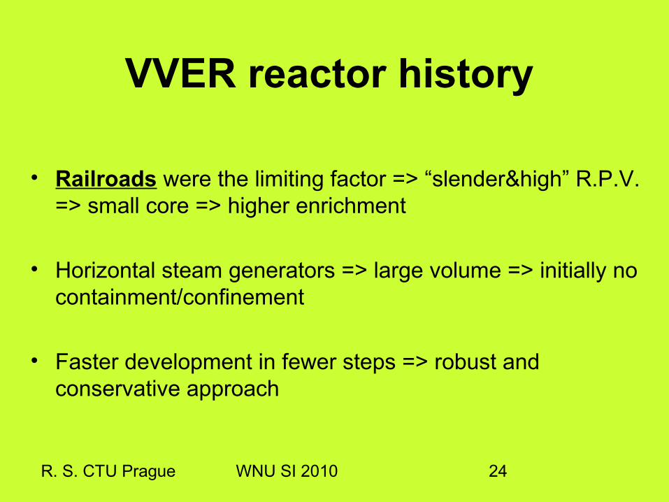
VVER reactor history

R. S. CTU Prague WNU SI 2010 23
MOTTO: Build and ship around…
R. S. CTU Prague WNU SI 2010 24
VVER reactor history
• Railroads were the limiting factor => “slender&high” R.P.V. => small core => higher enrichment
• Horizontal steam generators => large volume => initially no containment/confinement
• Faster development in fewer steps => robust and conservative approach

R. S. CTU Prague WNU SI 2010 25
VVER typical featuresCore: triangular lattice => hexagonal fuel assemblies
fuel assembly with grid 12.6mm
small core size => higher enrichment
Small RPV diameter => neutron damage on RPV
(156 mm water for VVER440 (V-230),
263 mm for VVER1000 (V-320) between fuel and RPV)
=> “high” RPV (esp. for VVER440)
Primary circuit: more loops (6 for VVER440)=>more water
horizontal steam generators=>less sediments
Safety: VVER440 (V-230): LOCA: 32mm diameter, weak ECCS
From VVER440(V-213): LOCA: full rupture, standard ECCS

R. S. CTU Prague WNU SI 2010 26
VVER typical featuresVVER 440: very efficient control rods
-different design than in other PWR
- effort of being robust and simple
- large worth, quick scram
-resulting in a ”long” RPV which also means a lot of water…
-unusual burnout of fuel attached to the control rod
-safety studies: control rod ejection is more dramatic than PWR
VVER 1000: standard approach to control rods, like PWR

Before I show you the reactors...
R. S. CTU Prague WNU SI 2010
Q U I Z time! a/ VVERb/ BWRc/ RBMK
d/ CANDUe/ PWR

R. S. CTU Prague WNU SI 2010 28
VVER 440
Courtesy of Skoda-JS

R. S. CTU Prague WNU SI 2010 29
NPP VVER 440 (V 230)

R. S. CTU Prague WNU SI 2010 30
VVER 440 V-213

R. S. CTU Prague WNU SI 2010 31
NPP VVER 440 (V 213)

R. S. CTU Prague WNU SI 2010 32
VVER 440, reactor hall cross section

R. S. CTU Prague WNU SI 2010 33
VVER 440 – primary circuit
Courtesy of Skoda-JS

R. S. CTU Prague WNU SI 2010 34
VVER 440 – steam generator
Courtesy of Skoda-JS

R. S. CTU Prague WNU SI 2010 35
VVER 440 – RPV cross section in 2 levels
Courtesy of Skoda-JS

R. S. CTU Prague WNU SI 2010 36
VVER 440 – fuel pin and fuel assembly

R. S. CTU Prague WNU SI 2010 37
VVER 440 Dukovany, Loviisa

Reactor type VVER 440 (V 213) VVER 1000 (V320)
Thermal power 1375 MW 3000 MW
RPV diameter 3.56 m 4.5 m
RPV height 11.8 m 10.9 m# of fuel assemblies 312 163Fuel load 42 t 92 t
Moderator/coolant H2O H2O
RPV pressure 12.25 MPa 15.7 MPaCoolant temperature 267 °C - 297 °C 290 °C - 320 °C
R. S. CTU Prague WNU SI 2010 38
2 x 10004 x 440
VVER 440 x VVER 1000 comparison

R. S. CTU Prague WNU SI 2010 39
VVER 1000 V320
Courtesy of Skoda-JS

R. S. CTU Prague WNU SI 2010 40
Main parts:VVER 1000 reactor:
R. S. CTU Prague WNU SI 2010 41
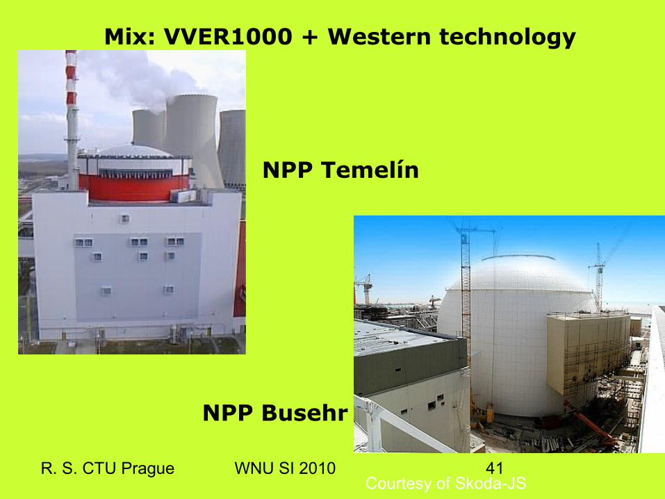
Mix: VVER1000 + Western technology
NPP Temelín
NPP Busehr
Courtesy of Skoda-JS

R. S. CTU Prague WNU SI 2010 42
Currently building: AES-92 = VVER1000 V392 (Belene)
Primary circuit: Number of loops 4Coolant pressure 15.7 MPa
Core inlet temperature 291°C
Core outlet temperature 321°CFA number 163
# of control rods 121
Maximum FA burn-up >60 MWd/kgU
R. S. CTU Prague WNU SI 2010 43
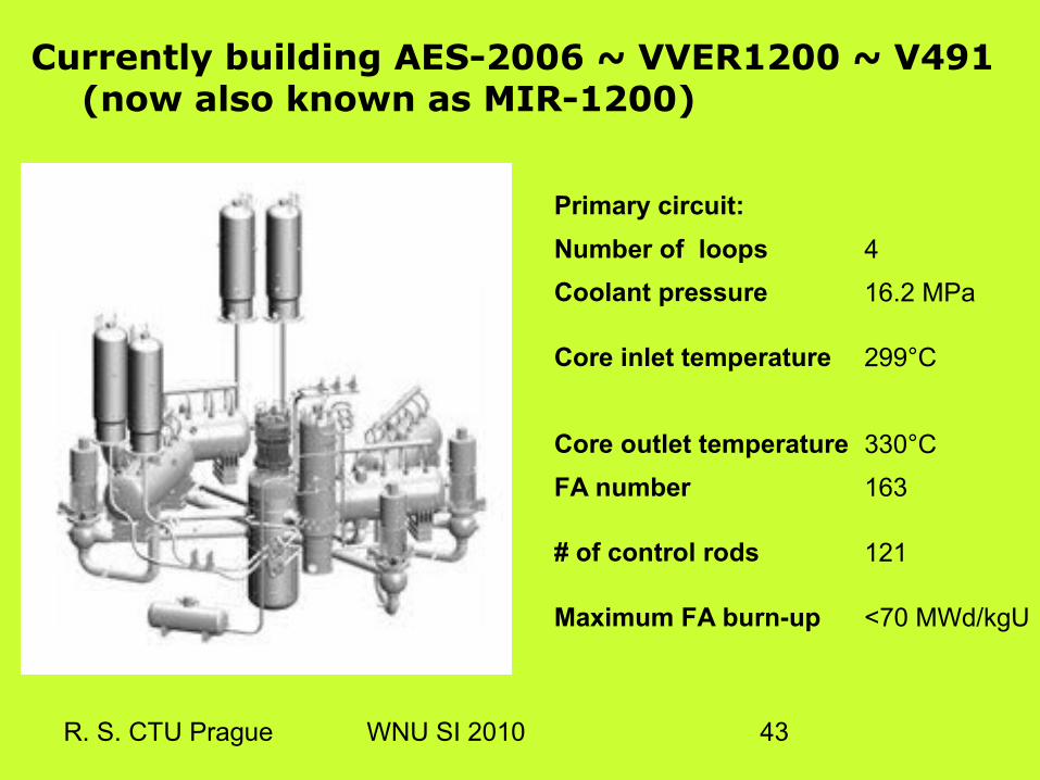
Currently building AES-2006 ~ VVER1200 ~ V491 (now also known as MIR-1200)
Primary circuit:
Number of loops 4Coolant pressure 16.2 MPa
Core inlet temperature 299°C
Core outlet temperature 330°CFA number 163
# of control rods 121
Maximum FA burn-up <70 MWd/kgU

All can be seen at the “cradle” of VVER reactors
R. S. CTU Prague WNU SI 2010NOVOVORONEZH
R. S. CTU Prague WNU SI 2010 45
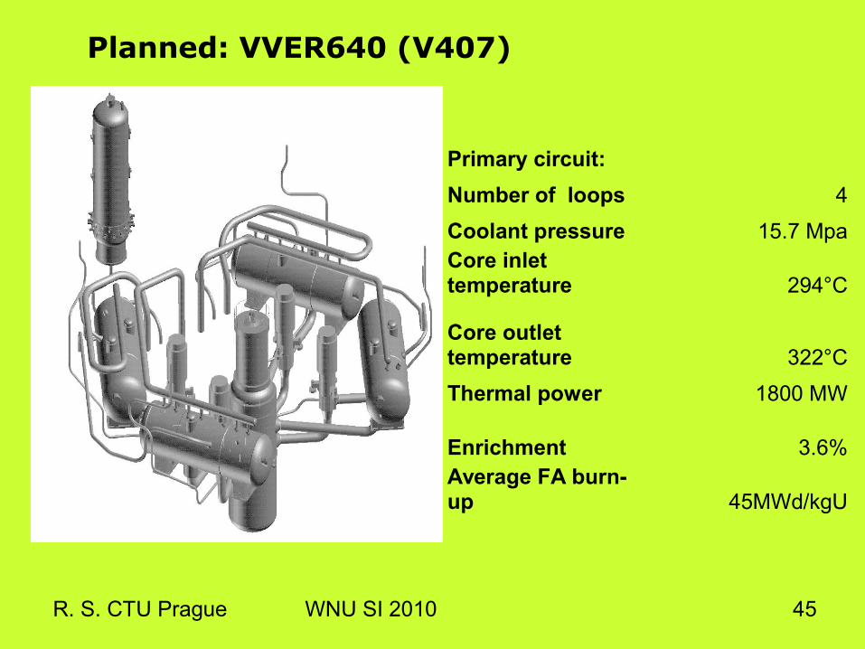
Planned: VVER640 (V407)
Primary circuit: Number of loops 4Coolant pressure 15.7 MpaCore inlet temperature 294°C
Core outlet temperature 322°CThermal power 1800 MW
Enrichment 3.6%Average FA burn-up 45MWd/kgU

R. S. CTU Prague WNU SI 2010 46
Planned: VVER1500
Primary circuit: Number of loops 4Coolant pressure 15.7 MpaCore inlet temperature 299°C
Core outlet temperature 330°CThermal power 4250 MW
Enrichment 4.4%Average FA burn-up 45-55MWd/kgU

R. S. CTU Prague WNU SI 2010 47
VVER-1200 a.k.a. MIR-1200 a.k.a. V-491 a.k.a. AES-2006.
Newest VVER type currently offered:
Courtesy of Skoda-JS
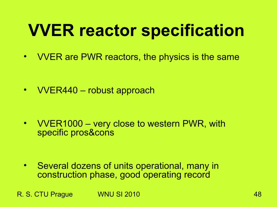
• VVER are PWR reactors, the physics is the same
• VVER440 – robust approach
• VVER1000 – very close to western PWR, with specific pros&cons
• Several dozens of units operational, many in construction phase, good operating record
R. S. CTU Prague WNU SI 2010 48
VVER reactor specification

R. S. CTU Prague WNU SI 2010 49
4. Which reactor is good / bad?Several PERFORMANCE indicators:
• Availibility factor• Load factor• Capacity factor• Operating factor...
Also: SAFETY + SECURITY indicators (WANO/INPO lectures to come)

R. S. CTU Prague WNU SI 2010 50
IAEA website helps too! VVER440

R. S. CTU Prague WNU SI 2010 51
IAEA website helps... VVER1000
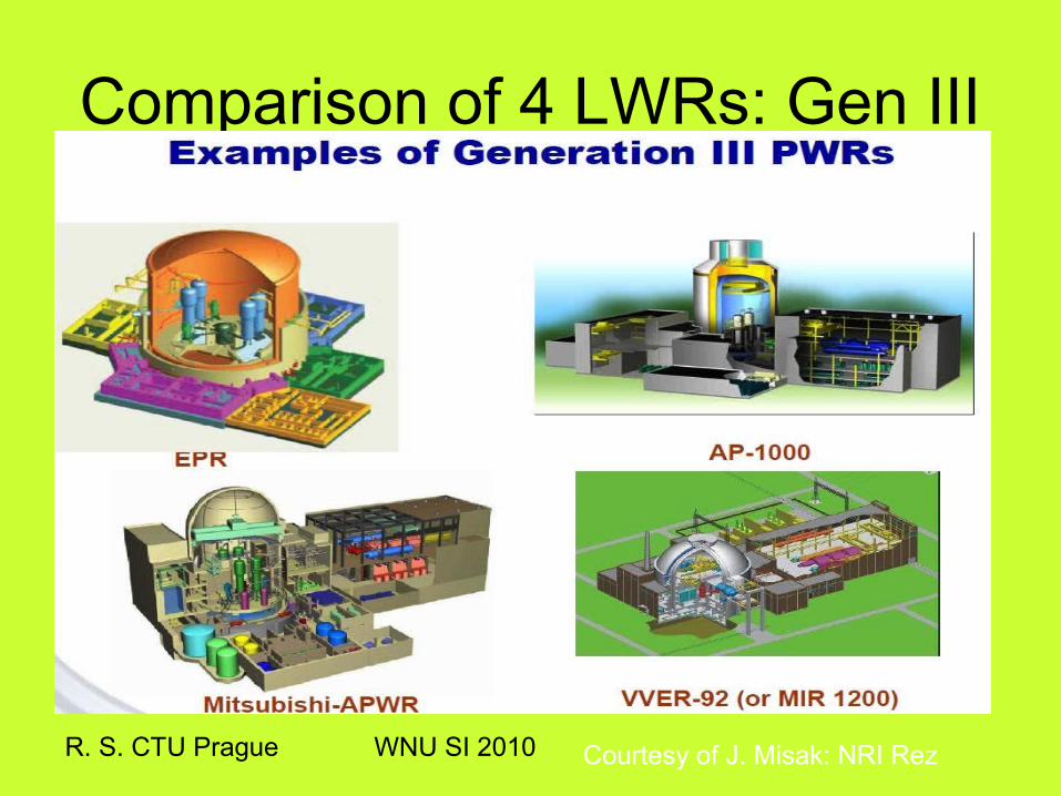
Comparison of 4 LWRs: Gen III
R. S. CTU Prague WNU SI 2010 Courtesy of J. Misak: NRI Rez

Comparison of 4 PWRs: Gen III
R. S. CTU Prague WNU SI 2010 Courtesy of J. Misak: NRI Rez

R. S. CTU Prague WNU SI 2010 54
THANK YOU
(15 BACK UP SLIDES READY AND ENCLOSED WITH DATA FOR EAGER READERS...)

Comparison of 4 PWRs: Gen III
R. S. CTU Prague WNU SI 2010 Courtesy of J. Misak: NRI Rez

R. S. CTU Prague WNU SI 2010 56
VVER performance
Courtesy of D. Gilchrist, ENEL

R. S. CTU Prague WNU SI 2010 57
VVER reactor history: “Voronezh” types PROTOTYPES
Power/ MWe
Place Start Decommissioned
VVER 210
210 Novovoronezh 1964 1988
VVER 70 70 Rheinsberg 1966 1990
VVER 365
365 Novovoronezh 1970 1990

R. S. CTU Prague WNU SI 2010 58
VVER reactor history: “Voronezh” types VVER 440 (i.e. rated 440MWe) “1st
generation”Feature Place Start
V 170 Novovoronezh 1972
V 230 Kola 1973
V 270 seismic Armenia 1980
VVER for export, RBMK for home:
17 VVER440 units built, 13 out of Russia

R. S. CTU Prague WNU SI 2010 59
VVER reactor history: “Voronezh” types VVER 440 “2nd generation” (i.e. project after`70)
Feature Place Commissioned
V 213 Kola 1982
V 213 Ice + containment Loviisa 1977
V 213 condenser Dukovany 1985Again for export: 18 units built, 16 out of Russia

R. S. CTU Prague WNU SI 2010 60
VVER reactor history: “Voronezh” types VVER 1000 (i.e. power 1000MWe) “2nd generation”
Place Commissioned
V 178 Novovoronezh 1981
V 302 Nikolajev 1983
V 338 Kalinin 1985
V 320 Balakovo 1986
More than 20 units built, other still in construction..
R. S. CTU Prague WNU SI 2010 61
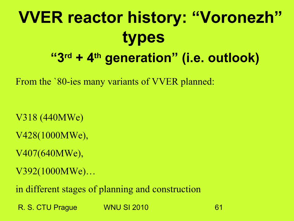
VVER reactor history: “Voronezh” types
“3rd + 4th generation” (i.e. outlook)From the `80-ies many variants of VVER planned:
V318 (440MWe)
V428(1000MWe),
V407(640MWe),
V392(1000MWe)…
in different stages of planning and construction

R. S. CTU Prague WNU SI 2010 62
VVER 1000 comparison – design parameters
V-320 V-320Temelín
V-428 V-466
Thermal Power, MW 3000 3000 3000 3000
Fuel cycle, years 3 4 3-4 3-4
Average burn out, MWd/kgU 40.2 43.3 43 47.2
Enrichment, % 4.4 3-3.8 3.9 4.28
Profiled fuel no yes ? ?
Annual load factor, hours 7000 7000 7000 8400
Planned lifetime, years 30 30-40 40 60
LBB (Leak Before Break) no yes yes yes
Probability of core melting 10Е-5 10Е-5 10Е-5 10Е-6
ATWS no yes yes yes
ECCS concept 3х100% 3х100% 4х100% 4х100%
Double containment no no yes yes
Core catcher no no yes yes
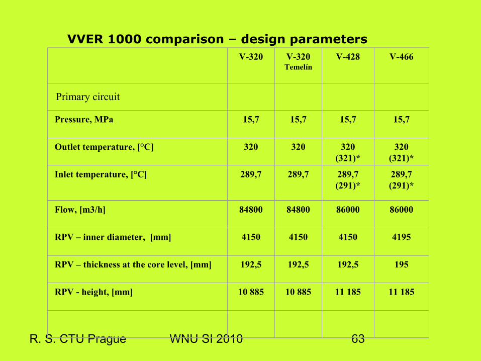
R. S. CTU Prague WNU SI 2010 63
V-320 V-320Temelín
V-428 V-466
Pressure, MPa 15,7 15,7 15,7 15,7
Outlet temperature, [°C] 320 320 320 (321)*
320 (321)*
Inlet temperature, [°C] 289,7 289,7 289,7 (291)*
289,7 (291)*
Flow, [m3/h] 84800 84800 86000 86000
RPV – inner diameter, [mm]
4150 4150 4150 4195
RPV – thickness at the core level, [mm] 192,5 192,5 192,5 195
RPV - height, [mm] 10 885 10 885 11 185 11 185
VVER 1000 comparison – design parameters
Primary circuit

R. S. CTU Prague WNU SI 2010 64
NPP Loviisa
VVER 440

Loviisa
R. S. CTU Prague WNU SI 2010

R. S. CTU Prague WNU SI 2010 66
VVER 440 V 213

AES-92: BELENE
R. S. CTU Prague WNU SI 2010

R. S. CTU Prague WNU SI 2010 68
LWR positive/negative void…
R. S. CTU Prague WNU SI 2010 69
Void coefficient... in “my” reactor