v-series systems implementation guide for ibm® storageehashman/netapp/v-series/ig_ibm.pdf ·...
TRANSCRIPT
V-Series SystemsImplementation Guide for IBM® Storage
NetApp, Inc.495 East Java DriveSunnyvale, CA 94089 U.S.A.Telephone: +1 (408) 822-6000Fax: +1 (408) 822-4501Support telephone: +1 (888) 4-NETAPPDocumentation comments: [email protected] Web: http://www.netapp.com
Part number: 210-04510_A0July 2009

Copyright and trademark information
Copyright information
Copyright © 1994-2009 NetApp, Inc. All rights reserved. Printed in the U.S.A.
Software derived from copyrighted NetApp material is subject to the following license and disclaimer:
THIS SOFTWARE IS PROVIDED BY NETAPP “AS IS” AND WITHOUT ANY EXPRESS OR IMPLIED WARRANTIES, INCLUDING, BUT NOT LIMITED TO, THE IMPLIED WARRANTIES OF MERCHANTABILITY AND FITNESS FOR A PARTICULAR PURPOSE, WHICH ARE HEREBY DISCLAIMED. IN NO EVENT SHALL NETAPP BE LIABLE FOR ANY DIRECT, INDIRECT, INCIDENTAL, SPECIAL, EXEMPLARY, OR CONSEQUENTIAL DAMAGES (INCLUDING, BUT NOT LIMITED TO, PROCUREMENT OF SUBSTITUTE GOODS OR SERVICES; LOSS OF USE, DATA, OR PROFITS; OR BUSINESS INTERRUPTION) HOWEVER CAUSED AND ON ANY THEORY OF LIABILITY, WHETHER IN CONTRACT, STRICT LIABILITY, OR TORT (INCLUDING NEGLIGENCE OR OTHERWISE) ARISING IN ANY WAY OUT OF THE USE OF THIS SOFTWARE, EVEN IF ADVISED OF THE POSSIBILITY OF SUCH DAMAGE.
NetApp reserves the right to change any products described herein at any time, and without notice. NetApp assumes no responsibility or liability arising from the use of products described herein, except as expressly agreed to in writing by NetApp. The use or purchase of this product does not convey a license under any patent rights, trademark rights, or any other intellectual property rights of NetApp.
The product described in this manual may be protected by one or more U.S.A. patents, foreign patents, or pending applications.
RESTRICTED RIGHTS LEGEND: Use, duplication, or disclosure by the government is subject to restrictions as set forth in subparagraph (c)(1)(ii) of the Rights in Technical Data and Computer Software clause at DFARS 252.277-7103 (October 1988) and FAR 52-227-19 (June 1987).
Trademark information
NetApp, the Network Appliance logo, the bolt design, NetApp—the Network Appliance Company, Cryptainer, Cryptoshred, DataFabric, DataFort, Data ONTAP, Decru, FAServer, FilerView, FlexClone, FlexVol, Manage ONTAP, MultiStore, NearStore, NetCache, NOW NetApp on the Web, SANscreen, SecureShare, SnapDrive, SnapLock, SnapManager, SnapMirror, SnapMover, SnapRestore, SnapValidator, SnapVault, Spinnaker Networks, SpinCluster, SpinFS, SpinHA, SpinMove, SpinServer, StoreVault, SyncMirror, Topio, VFM, VFM (Virtual File Manager), and WAFL are registered trademarks of NetApp, Inc. in the U.S.A. and/or other countries. gFiler, Network Appliance, SnapCopy, Snapshot, and The evolution of storage are trademarks of NetApp, Inc. in the U.S.A. and/or other countries and registered trademarks in some other countries. The NetApp arch logo; the StoreVault logo; ApplianceWatch; BareMetal; Camera-to-Viewer; ComplianceClock; ComplianceJournal; ContentDirector; ContentFabric; EdgeFiler; FlexShare; FPolicy; Go Further, Faster; HyperSAN; InfoFabric; Lifetime Key Management, LockVault; NOW; ONTAPI; OpenKey, RAID-DP; ReplicatorX; RoboCache; RoboFiler; SecureAdmin; Serving Data by Design; Shadow Tape; SharedStorage; Simplicore; Simulate ONTAP; Smart SAN; SnapCache; SnapDirector; SnapFilter; SnapMigrator; SnapSuite; SohoFiler; SpinMirror; SpinRestore; SpinShot; SpinStor; vFiler; Virtual File Manager; VPolicy; and Web Filer are trademarks of NetApp, Inc. in the U.S.A. and other countries. NetApp Availability Assurance and NetApp ProTech Expert are service marks of NetApp, Inc. in the U.S.A.
ii Copyright and trademark information
IBM, the IBM logo, and ibm.com are trademarks or registered trademarks of International Business Machines Corporation in the United States, other countries, or both. A complete and current list of other IBM trademarks is available on the Web at http://www.ibm.com/legal/copytrade.shtml.
Apple is a registered trademark and QuickTime is a trademark of Apple, Inc. in the U.S.A. and/or other countries. Microsoft is a registered trademark and Windows Media is a trademark of Microsoft Corporation in the U.S.A. and/or other countries. RealAudio, RealNetworks, RealPlayer, RealSystem, RealText, and RealVideo are registered trademarks and RealMedia, RealProxy, and SureStream are trademarks of RealNetworks, Inc. in the U.S.A. and/or other countries.
All other brands or products are trademarks or registered trademarks of their respective holders and should be treated as such.
NetApp, Inc. is a licensee of the CompactFlash and CF Logo trademarks. NetApp, Inc. NetCache is certified RealSystem compatible.
Copyright and trademark information iii

iv Copyright and trademark information

Table of Contents
Preface . . . . . . . . . . . . . . . . . . . . . . . . . . . . . . . . . . . . . vii
Chapter 1 Implementation Overview . . . . . . . . . . . . . . . . . . . . . . . . . . . 1
IBM terminology . . . . . . . . . . . . . . . . . . . . . . . . . . . . . . . . . 3
Supported IBM storage arrays . . . . . . . . . . . . . . . . . . . . . . . . . . 4
License Internal Code and controller firmware. . . . . . . . . . . . . . . . . . 6
Guidelines for array LUN sizing . . . . . . . . . . . . . . . . . . . . . . . . . 7
Zoning for IBM storage arrays . . . . . . . . . . . . . . . . . . . . . . . . . 10
Chapter 2 Configurations Supported with IBM Arrays . . . . . . . . . . . . . . . . 11
Your guide to interpreting the illustrations . . . . . . . . . . . . . . . . . . . 12
Direct-attached configurations . . . . . . . . . . . . . . . . . . . . . . . . . 16
Fabric-attached HA pair configurations (non-GF270c systems) . . . . . . . 18
Configurations with a GF270c . . . . . . . . . . . . . . . . . . . . . . . . . 32
Fabric-attached configurations that optimize performance. . . . . . . . . . . 36
Chapter 3 Configuring DS8xxx arrays . . . . . . . . . . . . . . . . . . . . . . . . . . 41
DS8xxx configuration requirements . . . . . . . . . . . . . . . . . . . . . . 42
DS8xxx configuration overview . . . . . . . . . . . . . . . . . . . . . . . . 44
DS8xxx configuration with multiple LUN groups . . . . . . . . . . . . . . . 46
Chapter 4 Configuring DS4xxx/DS5xxx arrays . . . . . . . . . . . . . . . . . . . . . 51
DS4xxx/DS5xxx configuration requirements . . . . . . . . . . . . . . . . . 52
DS4xxx/DS5xxx configuration overview . . . . . . . . . . . . . . . . . . . 53
DS4xxx/DS5xxx configuration with multiple LUN groups . . . . . . . . . . 55
Chapter 5 Configuring ESS arrays. . . . . . . . . . . . . . . . . . . . . . . . . . . . 59
ESS configuration requirements . . . . . . . . . . . . . . . . . . . . . . . . 60
Table of Contents v

ESS configuration overview . . . . . . . . . . . . . . . . . . . . . . . . . . 61
Appendix A DS4xxx firmware upgrade issue workaround . . . . . . . . . . . . . . . . 65
Index . . . . . . . . . . . . . . . . . . . . . . . . . . . . . . . . . . . . . . 71
vi Table of Contents

Preface
About this guide This guide provides information about how to set up your storage array to work with a V-Series system running Data ONTAP® software, including configuration guidelines and sample configurations. The information in this guide pertains to all supported V-Series platforms.
NoteData ONTAP software runs on multiple hardware platforms. This documentation might describe features that are not supported on your platform.
Audience This guide is for system administrators who are familiar with operating systems such as UNIX® and Windows® and who will be installing V-Series systems. This guide does not discuss basic system or network administration topics, such as IP addressing, routing, and network topology; it emphasizes the characteristics of the V-Series system.
Relationship of this guide to other guides
This guide is intended to be used in conjunction with other information in the V-Series and Data ONTAP libraries. The following table describes the relationships between this guide and other documentation.
Guide name Information includes...
Installation Requirements and Reference Guide
◆ General guidelines for creating and making array LUNs available to V-Series systems.
◆ Quick start installation instructions for connecting devices together and for installing Data ONTAP on a V-Series system that uses only third-party storage
◆ Reference information
◆ Detailed background information including layout in aggregates and checksums
Implementation Guides ◆ Vendor-specific details about how to set up a storage array to work with V-Series systems.
◆ More detailed configuration examples than are provided in the Installation Requirements and Reference Guide.
Preface vii

See the V-Series Support Matrix for details about Data ONTAP releases that support V-Series, supported switches, supported firmware, capacity, and maximum array LUN count.
Special messages This guide contains special messages that are described as follows:
NoteA note contains important information that helps you install or operate the system efficiently.
AttentionAttention contains instructions that you must follow to avoid damage to the equipment, a system crash, or loss of data.
Implementation Guide for Native Disk Shelves
Information about setting up the storage on the native disk shelves connected to the V-Series system.
V-Series Setup, Installation, and Management Guide (Data ONTAP 7.3.x releases) or the Data ONTAP software setup guides
Detailed steps for setting up the V-Series system, including information about installing Data ONTAP software for installations using only third-party storage. These guides are most helpful to installers who are new to Data ONTAP setup and installation.
Data ONTAP guides Detailed information about all Data ONTAP features used by all systems running Data ONTAP, for example, storage features and data protection features.
Guide name Information includes...
viii Preface

Chapter 1: Implementation Overview
1
Implementation OverviewAbout this chapter This chapter provides information about the IBM® storage array models and firmware that V-Series systems support, and guidelines specific to sizing array LUNs for V-Series on IBM storage arrays. Configuration requirements for setting up an IBM storage array with a V-Series system are in later chapters.
Topics in this chapter
This chapter contains the following topics:
◆ “IBM terminology” on page 3
◆ “Supported IBM storage arrays” on page 4
◆ “License Internal Code and controller firmware” on page 6
◆ “Guidelines for array LUN sizing” on page 7
◆ “Zoning for IBM storage arrays” on page 10
Generic storage allocation terms used in this document
array LUN: This guide uses the term array LUN (logical unit number) to describe an area on the storage array that is available for a V-Series system or a non V-Series host to read data from or write data to. You might be accustomed to hearing a different term to describe this area; the term varies among vendors and sometimes among platforms for the same vendor. See the V-Series Implementation Guide for your storage array type for the specific term used for your platforms.
HA pair: Two storage systems (nodes) whose controllers are connected to each other either directly or through switches. In some versions of Data ONTAP, this configuration is referred to as an active/active configuration.
Additional information to read
This guide is intended to be used in conjunction with the following additional documents:
◆ V-Series Installation Requirements and Reference Guide
This guide contains general guidelines for setting up the storage array to work with the V-Series systems. When planning your deployment, first read this guide, then read the V-Series Implementation Guide for your storage array type. The Implementation Guides provide additional details that are specific to your vendor.
◆ V-Series Support Matrix at http://now.netapp.com
1

This document provides information about Data ONTAP releases that support V-Series, supported switches, supported firmware, capacity, and maximum array LUN count.
NoteThe Support Matrix is the final authority on the storage array models, storage array firmware, switches, and so on that V-Series supports.
2 Implementation Overview

IBM terminology
array A collection of Fibre Channel or SATA hard drives that are logically grouped together. All the drives in the array are assigned the same RAID level. An array is sometimes referred to as a RAID set in DS4xxx/DS5xxx models.
host group An entity in the storage partition topology that defines a logical collection of host computers that require shared access to one or more logical drives.
volume IBM uses the term volume to describe the area on the storage array that is available for a V-Series system or non V-Series host to read data from or write data to. The V-Series documentation uses the term array LUN to describe this area.
IBM volumes are not the same as Data ONTAP volumes. A Data ONTAP volume is a logical entity that holds user data that is accessible through one or more of the access protocols supported by Data ONTAP, including Network File System (NFS), Common Internet File System (CIFS), HyperText Transfer Protocol (HTTP), Fibre Channel Protocol (FCP), and Internet SCSI (iSCSI). V-Series treats an IBM volume as a disk.
volume group A DS8xxx volume group is used to control the hosts that can access array LUNs (LUN masking) by associating host attachments or port groups with the array LUNs that they are allowed to access. You assign the desired FC initiator ports and the array LUNs to be accessed to the same volume group.
Chapter 1: Implementation Overview 3

Supported IBM storage arrays
Finding out which Data ONTAP release supports which storage arrays
This guide provides information about all vendors and storage arrays that V-Series supports at the time of publication. Not all vendors and models described in this guide are supported in all Data ONTAP releases. See the V-Series Support Matrix at http://now.netapp.com to determine which vendors and storage array models are supported in a particular Data ONTAP release.
NoteThe V-Series Support Matrix is the final authority about which storage arrays and configurations that V-Series systems support.
Supported storage arrays
At the time of publication of this guide, V-Series systems support the IBM storage array platforms in this section.
NoteIn the context of this discussion, storage arrays in the same family share the same performance and failover characteristics. For example, members of the same family all perform active-active failover or they all perform active-passive failover. Storage arrays with 4-GB HBAs are not considered to be in the same family as storage arrays with 2-GB HBAs. When you set up a Data ONTAP aggregate, you cannot assign array LUNs from different storage array families or different vendors to the same aggregate.
ESS series family:
◆ IBM ESS Model 800, ESS Model 800 Turbo
◆ IBM ESS Model 750
◆ IBM Model F10
◆ IBM Model F20
DS4000 series families:
◆ DS4xxx model family 1
❖ IBM Model DS4800
❖ IBM Model DS4700
❖ IBM Model DS4200
◆ DS4xxx model family 2
4 Supported IBM storage arrays

❖ IBM Model DS4500
❖ IBM Model DS4400
❖ IBM Model DS4300, DS4300 Turbo
◆ DS4xxx model family 3
❖ IBM Model DS4100
DS5000 series family:
◆ IBM Model DS5100
◆ IBM Model DS5300
DS8000 series family:
◆ IBM Model DS8300 922
◆ IBM Model DS8300 9A2 (LPAR, system logical partitions)
◆ IBM Model DS8100 921
DS8000 Turbo series family:
◆ IBM Model DS8100 931
◆ IBM Model DS8300 932
◆ IBM Model DS8300 9B2
NoteDS8xxx, DS5xxx, and DS4xxx are used in this guide when the information applies to all models in a series family that V-Series supports. If the information is specific to a particular model, the actual model number is used.
Chapter 1: Implementation Overview 5
License Internal Code and controller firmware
Where to find information about supported versions
See the V-Series Support Matrix at http://now.netapp.com for information about the IBM storage array license code or firmware controller versions. The Support Matrix is the final authority on the License Internal Code and firmware controller versions that V-Series supports.
Live upgrade of firmware
Live upgrade of the controller firmware is not supported on the DS4xxx storage arrays.
AttentionSee Appendix A, “DS4xxx firmware upgrade issue workaround,” on page 65.
6 License Internal Code and controller firmware

Guidelines for array LUN sizing
Relationship of Data ONTAP and storage array units of measure
The size of the array LUNs that you can create on the storage array is limited by the minimum and maximum array LUN sizes that Data ONTAP supports. The Data ONTAP definition of a gigabyte (GB) might not match the definition of a GB for your storage array. When you determine the minimum and maximum array LUN sizes for your storage array, you need to consider whether the units of measure for your storage array are different from Data ONTAP units of measure.
The Data ONTAP definition of a GB is as follows:
One GB is equal to 1000 x 1024 x 1024 bytes.
See the V-Series Support Matrix for the general rule about Data ONTAP minimum and maximum array LUN sizes. Each V-Series Implementation Guide contains specific information about the equivalent minimum and maximum limits according to the vendor’s calculation of units of measure.
Minimum array LUN size for the root volume
The minimum array LUN size shown in this section does not apply to the array LUN for the root volume. It is strongly recommended that you do not set the size of a root volume below the minimum root volume size shown in the V-Series Support Matrix. The reason is that you want to ensure that there is sufficient space in the root volume for system files, log files, and core files. If a system problem occurs, you need to provide these files to technical support.
Minimum and maximum array LUN value usable with IBM
IBM calculates units of measure differently than Data ONTAP. The maximum usable values shown in this section are based on the assumption that the units of measurement for your storage array are calculated as follows.
For this storage array... A GB is calculated as...
IBM ESS800 1000 x 1000 x 1000 bytes
IBM DS4xxx 1024 x 1024 x 1024 bytes
IBM DS5xxx 1024 x 1024 x 1024 bytes
IBM DS8xxx 1024 x 1024 x 1024 bytes
Chapter 1: Implementation Overview 7

NoteStorage arrays vary as to how you can specify array LUN size (that is, in GB, MB, or 512-byte blocks).
Do not create array LUNs that are smaller than the minimum LUN size shown in the V-Series Support Matrix.
See the V-Series Installation Requirements and Reference Guide for guidelines about the implications of different size array LUNs on Data ONTAP storage.
Maximum array LUN value usable with DS4xxx, DS5xxx, and DS8xxx storage arrays
If you plan to use a large-sized array LUN that is close to the maximum array LUN size that Data ONTAP supports, ensure that you specify its size as shown in the “Maximum usable value” column in the tables in this section.
Values for Data ONTAP 7.2.4 and later:
Values for Data ONTAP 7.2.3:
Values for Data ONTAP 7.2.2 and earlier:
If you are specifying in... Maximum usable value
GB 976 GB
MB 975,000 MB
512-byte blocks 2,047,500,000 512-user blocks
If you are specifying in... Maximum usable value
GB 732 GB
MB 749,000 MB
512-byte blocks 1,535,500,000 512-byte blocks
If you are specifying in... Maximum usable value
GB 488.281 GB
MB 500,000 MB
512-byte blocks 1,024,000,000 512-byte blocks
8 Guidelines for array LUN sizing

Maximum array LUN value usable with ESS800 storage arrays
If you plan to use a large-sized array LUN that is close to the maximum array LUN size that Data ONTAP supports, ensure that you specify its size as shown in the “Maximum usable value” column in the tables in this section.
Values for Data ONTAP 7.2.4 and later:
Values for Data ONTAP 7.2.3:
Values for Data ONTAP 7.2.2 and earlier:
If you are specifying in... Maximum usable value
GB 1,023 GB
MB 1,022,000 MB
512-byte blocks 2,047,500,000 512-user blocks
If you are specifying in... Maximum usable value
GB 786 GB
MB 785,000 MB
512-byte blocks 1,535,500,000 512-byte blocks
If you are specifying in... Maximum usable value
GB 524 GB
Chapter 1: Implementation Overview 9
Zoning for IBM storage arrays
Zoning requirements
Zoning is required to prevent LUNs from being visible to a V-Series system on more than two target ports. You must configure zoning to restrict each initiator port to a single target port on each storage array. Data ONTAP requires that a LUN is only visible on one target port for each initiator port.
When you create LUNs on an IBM storage array, you assign each array LUN to a host group. A host group binds a group of LUNs to a set of V-Series FC initiator ports. The host group does not restrict which target ports an initiator can access the array LUNS through, therefore you must configure switch zoning to restrict each initiator port to a single target port on each storage array.
If zoning is not used, and there are multiple target ports from an array in a given fabric the V-Series initiator will see the same LUNs on all those target ports. Data ONTAP expects to see a LUN on one target port for each initiator.
Recommendation for single-initiator zoning
It is recommended that you use single-initiator zoning, which limits each zone to a single V-Series system FC initiator port. See Chapter 2, “Configurations Supported with IBM Arrays,” on page 11 for configuration examples with zoning information.
10 Zoning for IBM storage arrays

Chapter 2: Configurations Supported with IBM Arrays
2
Configurations Supported with IBM ArraysAbout this chapter This chapter discusses the supported configurations for all supported IBM storage arrays. Use the configurations in this chapter as guidelines when you connect your V-Series system to your storage array. You can also refer to the configurations when you determine desired capacity usage, create array LUNs initially, and assign array LUNs to your V-Series system.
NoteThe V-Series Support Matrix is the final authority about which configurations that V-Series systems support.
Topics in this chapter
This chapter discusses the following topics:
◆ “Your guide to interpreting the illustrations” on page 12
◆ “Direct-attached stand-alone configuration” on page 16
◆ “Fabric-attached HA pair configurations (non-GF270c systems)” on page 18
◆ “Configurations with a GF270c” on page 32
◆ “Fabric-attached configurations that optimize performance” on page 36
11

Your guide to interpreting the illustrations
How redundant paths and port pairs are shown
Illustration of redundant paths and port pairs for storage arrays: In each illustration in this chapter, the port pairs on the storage array are shown in relation to the LUNs on the port, with the ports on alternate controllers, clusters, or enclosures. (The hardware component on which host adapters and ports are located varies on different storage arrays.) Different storage array models, even those from the same vendor, might label the ports differently from those shown in the examples.
See the V-Series Installation Requirements and Reference Guide for rules for setting up redundant ports on the V-Series system and examples of valid and invalid configurations.
Illustration of redundant paths and port pairs for V-Series systems: On some V-Series systems, the FC initiator ports are on cards. On other models, the FC initiator ports are onboard ports and are labeled 0a, 0b, and so on. Some models include both cards and onboard ports. As you look through the illustrations, notice that on the V-Series system the connections from the V-Series FC initiator ports are set up for redundancy.
Relationship between V-Series port pairs and LUN groups: The illustrations in the following table show a V6xxx system, which has both onboard FC initiator ports and cards. These examples show the use of two different redundant port pairs. Redundancy is achieved on the V-Series system because each port in a pair is on a different bus.
Storagearray
Controller(cluster) 2
Controller(cluster) 1
2A1A LUNs 1-10
12 Your guide to interpreting the illustrations

Release Supported configurations
7.3 and later
For DS8xxx and DS4xxx/DS5xxx storage arrays only, you can use multiple port pairs on a V-Series system to access LUNs on the same storage array, if each V-Series port pair accesses a different group of LUNs and each V-Series port in a pair accesses a different fabric.
See “Fabric-attached configurations that optimize performance” on page 36 for examples of configurations with multiple port pairs and multiple LUN groups.
V-Series system
0a 0b 0c 0d 0e 0f 0g 0h
FC initiator port pair to a LUN set overtwo independent fabrics
FC initiator port pair to a different LUNset over two independent fabrics
Chapter 2: Configurations Supported with IBM Arrays 13

The following illustration shows a redundant port pair on a V-Series model that uses cards.
One port on each of two different cards is configured to ensure redundancy to the port pair on the storage array. Then, if one card fails, the port on the other card is used. You can use either port on a card.
Earlier than 7.3
To use multiple V-Series port pairs with an IBM storage array, you must follow these rules:
◆ Each port in a V-Series port pair must access a different fabric.
◆ No more than one port pair on a specific V-Series system can access LUNs on that storage array.
◆ For a V-Series HA pair, one port pair from each V-Series system must be able to see the same array LUNs.
Release Supported configurations
FC initiator pair to one storage subsystemover two independent fabrics
FC initiator pair to a different storagesubsystem over two independent fabrics
V-Series system
0a 0b 0c 0d 0e 0f 0g 0h
V-Series system
FC port
FC port2A1A
1B 2B
14 Your guide to interpreting the illustrations
NoteThe illustrations show two cards, one with FC ports 1A and 1B and the other with FC ports 2A and 2B. The number represents the slot.
For more information about selecting redundant ports on the different V-Series models with onboard FC initiator ports, see the V-Series Installation Requirements and Reference Guide.
Chapter 2: Configurations Supported with IBM Arrays 15

Direct-attached configurations
Direct-attached stand-alone configuration
The following illustration shows an example of a direct-attached stand-alone configuration with 336 LUNs allocated for the V-Series system:
◆ For an ESS storage array, you can allocate up to 336 LUNs, as shown in the following illustration, if the V-Series model supports 336 LUNs.
◆ For DS4xxx, DS5xxx, and DS8xxx storage arrays, you can allocate up to 256 LUNs for each LUN group V-Series system.
NoteThe V-Series Support Matrix is the final authority about which configurations that V-Series systems support.
Direct-attached HA pair configuration (non GF270c)
The following illustration shows a deployment with a V-Series HA pair that is directly connected to the storage array. The storage array in this example has allocated 256 LUNs for the V-Series systems.
V-Series system
0a 0b 0c 0d 0e 0f 0g 0h
Storagesubsystem
Controller(cluster) 2
Controller(cluster) 1
2A1A LUNs 1-336
16 Direct-attached configurations

In this illustration, the solid lines show the connections from V-Series system 1 and the dashed lines show the connections from V-Series system 2. For each V-Series system in a direct-attached configuration, you need one redundant port pair on the storage array to ensure that there are two paths to an array LUN. You use a total of four ports on the storage array for an HA pair, as shown in this example. Although four ports on the storage array are used to access the LUNs for V-Series, each V-Series system can see a particular LUN through only two redundant ports.
Use a redundant port pair on each V-Series node to ensure availability. (That is, on a V-Series model with cards, use one connection from each adapter. For a model with onboard ports, use one port from each bus.) Then, if one path from a V-Series node fails, the other path from the node is used; V-Series controller takeover does not occur.
Storagesubsystem
Controller(cluster) 2
Controller(cluster) 1
V-Series system 1 V-Series system 2
Clusterinterconnect cables
0a 0b 0c 0d 0a 0b 0c 0d
2A1A
2B1B
LUNs 1-256
Chapter 2: Configurations Supported with IBM Arrays 17

Fabric-attached HA pair configurations (non-GF270c systems)
Examples in this section
This section includes the following examples:
◆ “Fabric-attached stand-alone configuration” on page 18
◆ “Two ports accessed on a single storage array” on page 19
◆ “Two ports accessed on each storage array—Layout 1” on page 21
◆ “Two ports accessed on each storage array—Layout 2” on page 23
◆ “Four ports accessed on a single storage array— Layout 1” on page 25
◆ “Four ports accessed on a single storage array—Layout 2” on page 28
◆ “Four ports accessed on each storage array” on page 30
Zoning recommendation
It is recommended that you use single-initiator zoning, which limits each zone to a single V-Series system FC initiator port and one storage array port. Single-initiator zoning improves discovery and boot time because the V-Series FC initiators do not attempt to discover each other.
Fabric-attached stand-alone configuration
The following illustration shows a fabric-attached configuration for a stand-alone V-Series system, with 336 LUNs allocated for the V-Series system.
NoteNot all configurations can support 336 LUNs. See the V-Series Support Matrix for information about the number of array LUNs your V-Series model can support.
18 Fabric-attached HA pair configurations (non-GF270c systems)

Zoning: The following table shows single-initiator zoning for this example. Single-initiator zoning is the recommended zoning strategy.
Two ports accessed on a single storage array
This is an example of a fabric-attached HA pair in which the V-Series nodes share the two (redundant) storage array ports. This configuration uses the fewest number of ports that are possible for V-Series. This configuration is useful if you are limited in the number of storage array ports or switch ports that you can use with V-Series.
Zone Switch V-Series system port Storage array port
z1 1 0a 1A
z2 2 0h 2A
V-Series system
0a 0b 0c 0d 0e 0f 0g 0h
Storagesubsystem
Controller(cluster) 2
Controller(cluster) 1
2A1A LUNs 1-336
Switch 1 Switch 2
Chapter 2: Configurations Supported with IBM Arrays 19

In this example, 256 LUNs are allocated for the V-Series systems.
To ensure availability, use a redundant port pair on each V-Series system (that is, one connection from each adapter on a V-Series model with cards or a port from each bus for a model with onboard ports). Then, if one path from a V-Series node fails, the other path from the node is used; V-Series controller takeover does not occur.
Storagesubsystem
Controller(cluster) 2
Controller(cluster) 1
V-Series system 1 V-Series system 2
Clusterinterconnect cables
0a 0b 0c 0d 0a 0b 0c 0d
2A1A LUNs 1-256
Switch 1
z1 z3 z2 z4
z3/z4z1/z2
Switch 2
20 Fabric-attached HA pair configurations (non-GF270c systems)

Zoning: The following table shows single-initiator zoning for this example with a V3000 HA pair. Single-initiator zoning is the recommended zoning strategy.
Two ports accessed on each storage array—Layout 1
This is an example of a layout in which the V-Series nodes connect to two different storage arrays. The two storage arrays can be from the same vendor or from different vendors. You might want to use this type of layout if you need to use some V-Series FC initiator ports as targets (for example, to use the port pair 0b and 0d for FCP).
In this example, the solid connection lines represent Fabric 1 and the dashed connection lines represent Fabric 2. FC initiator ports 0a and 0c are a port pair; any array LUN seen on port 0a is also seen on port 0c.
Zone V-Series system Storage array
Switch 1
z1 V-Series system 1 Port 0a Controller 1 Port 1A
z2 V-Series system 2 Port 0a Controller 1 Port 1A
Switch 2
z3 V-Series system 1 Port 0c Controller 2 Port 2A
z4 V-Series system 2 Port 0c Controller 2 Port 2A
Chapter 2: Configurations Supported with IBM Arrays 21

Zoning: The following table shows single-initiator zoning for this example with a V3000 HA pair. Single-initiator zoning is the recommended zoning strategy.
Controller(cluster) 2
Controller(cluster) 1
V-Series system 1 V-Series system 2
Clusterinterconnect cables
0a 0b 0c 0d 0a 0b 0c 0d
Switch 1 Switch 2
Fabric 1
z3/z7 z2/z6 z4/z8z1/z5
z5/z6 z7/z8
z1/z2 z3/z4
Fabric 2
1B
2A
2BLUNs 1-136
Storagesubsystem 2
Controller(cluster) 2
Controller(cluster) 1
1A
1B
2A
2BLUNs 1-100
Storagesubsystem 1
1A
22 Fabric-attached HA pair configurations (non-GF270c systems)

Two ports accessed on each storage array—Layout 2
This example is similar to “Two ports accessed on each storage array—Layout 1” on page 21, but in this example two port pairs are used on each V-Series node. To use multiple V-Series port pairs with an IBM storage array, you must follow these rules:
◆ Each port in a V-Series port pair must access a different fabric.
◆ No more than one port pair on a specific V-Series system can access LUNs on that storage array.
◆ For a V-Series HA pair, one port pair from each V-Series system must be able to see the same array LUNs.
The two storage arrays can be from the same vendor or from different vendors.
Zone V-Series system Storage array
Switch 1
z1 V-Series system 1
Port 0a 1 Controller 1 Port 1A
z2 V-Series system 2
Port 0a 1 Controller 1 Port 1A
z5 V-Series system 1
Port 0a 2 Controller 1 Port 1A
z6 V-Series system 2
Port 0a 2 Controller 1 Port 1A
Switch 2
z3 V-Series system 1
Port 0c 1 Controller 2 Port 2A
z4 V-Series system 2
Port 0c 1 Controller 2 Port 2A
z7 V-Series system 1
Port 0c 2 Controller 2 Port 2A
z8 V-Series system 2
Port 0c 2 Controller 2 Port 2A
Chapter 2: Configurations Supported with IBM Arrays 23

In this example, the V-Series port pair 0a and 0c (the solid lines) connects to one storage array. Any array LUN seen on 0a is also seen on 0c on the other fabric. The V-Series port pair 0b and 0d (the dashed lines) connects to the other storage array. Any array LUN seen on 0b is also seen on 0d on the other fabric.
Zoning: The following table shows single-initiator zoning for this example with a V3000 HA pair. Single-initiator zoning is the recommended zoning strategy.
Controller(cluster) 2
Controller(cluster) 1
V-Series system 1 V-Series system 2
Clusterinterconnect cables
0a 0b 0c 0d 0a 0b 0c 0d
Switch 1 Switch 2
Fabric 1
z1 z5 z3 z7 z2 z6 z4 z8
z5/z6 z7/z8
z1/z2 z3/z4
Fabric 2
1B
2A
2BLUNs 1-136
Storagesubsystem 2
Controller(cluster) 2
Controller(cluster) 1
1A
1B
2A
2BLUNs 1-100
Storagesubsystem 1
1A
24 Fabric-attached HA pair configurations (non-GF270c systems)

Four ports accessed on a single storage array— Layout 1
The following illustration shows an example of a fabric-attached HA pair in which the V-Series nodes access array LUNs through four (redundant) ports on the storage array.
Connections between the switch and the storage array: In this layout, there is a straight connection from the storage array to the switch. (Compare this layout with the connections in “Four ports accessed on a single storage array—Layout 2” on page 28.)
Zone V-Series system Storage array
Switch 1
z1 V-Series system 1
Port 0a 1 Controller 1 Port 1A
z2 V-Series system 2
Port 0a 1 Controller 1 Port 1A
z5 V-Series system 1
Port 0b 2 Controller 1 Port 1A
z6 V-Series system 2
Port 0b 2 Controller 1 Port 1A
Switch 2
z3 V-Series system 1
Port 0c 1 Controller 2 Port 2A
z4 V-Series system 2
Port 0c 1 Controller 2 Port 2A
z7 V-Series system 1
Port 0d 2 Controller 2 Port 2A
z8 V-Series system 2
Port 0d 2 Controller 2 Port 2A
Chapter 2: Configurations Supported with IBM Arrays 25

Utilization of devices: In this layout, the following occurs with device failure:
◆ If a switch fails, all traffic goes to the same controller.
For example, if Switch 1 fails, the path from FC initiator port 0a on both V-Series systems is unavailable. Therefore, all traffic goes from FC initiator port 0c to Controller 2. No traffic can go to Controller 1.
◆ If a controller fails, all traffic goes through the same switch.
For example, if Controller 2 fails, traffic goes from V-Series system 1 port 0a and V-Series system 2 port 0a through Switch 1. No traffic can go through Switch 2.
See “Four ports accessed on a single storage array—Layout 2” on page 28 for an example that provides better utilization of the devices than in this layout if a switch or a controller (cluster) on the storage array becomes unavailable.
Storagesubsystem
Controller(cluster) 2
Controller(cluster) 1
V-Series system 1 V-Series system 2
Clusterinterconnect cables
0a 0b 0c 0d 0a 0b 0c 0d
1A
Switch 1 Switch 2
Fabric 1 Fabric 2
1B
2A
2BLUNs 1-256
z1 z3 z2 z4
z4z2
z3z1
26 Fabric-attached HA pair configurations (non-GF270c systems)

Zoning: The following table shows single-initiator zoning for this example with a V3000 HA pair. Single-initiator zoning is the recommended zoning strategy.
Zone V-Series system Storage array
Switch 1
z1 V-Series system 1
Port 0a Controller 1 Port 1A
z2 V-Series system 2
Port 0a Controller 1 Port 1B
Switch 2
z3 V-Series system 1
Port 0c Controller 2 Port 2A
z4 V-Series system 2
Port 0c Controller 2 Port 2B
Chapter 2: Configurations Supported with IBM Arrays 27
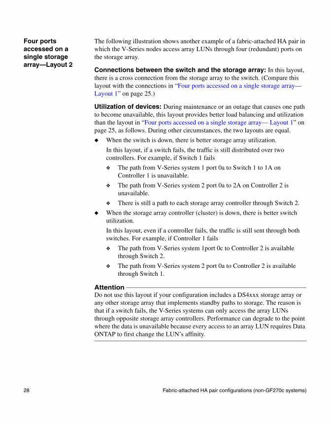
Four ports accessed on a single storage array—Layout 2
The following illustration shows another example of a fabric-attached HA pair in which the V-Series nodes access array LUNs through four (redundant) ports on the storage array.
Connections between the switch and the storage array: In this layout, there is a cross connection from the storage array to the switch. (Compare this layout with the connections in “Four ports accessed on a single storage array— Layout 1” on page 25.)
Utilization of devices: During maintenance or an outage that causes one path to become unavailable, this layout provides better load balancing and utilization than the layout in “Four ports accessed on a single storage array— Layout 1” on page 25, as follows. During other circumstances, the two layouts are equal.
◆ When the switch is down, there is better storage array utilization.
In this layout, if a switch fails, the traffic is still distributed over two controllers. For example, if Switch 1 fails
❖ The path from V-Series system 1 port 0a to Switch 1 to 1A on Controller 1 is unavailable.
❖ The path from V-Series system 2 port 0a to 2A on Controller 2 is unavailable.
❖ There is still a path to each storage array controller through Switch 2.
◆ When the storage array controller (cluster) is down, there is better switch utilization.
In this layout, even if a controller fails, the traffic is still sent through both switches. For example, if Controller 1 fails
❖ The path from V-Series system 1port 0c to Controller 2 is available through Switch 2.
❖ The path from V-Series system 2 port 0a to Controller 2 is available through Switch 1.
AttentionDo not use this layout if your configuration includes a DS4xxx storage array or any other storage array that implements standby paths to storage. The reason is that if a switch fails, the V-Series systems can only access the array LUNs through opposite storage array controllers. Performance can degrade to the point where the data is unavailable because every access to an array LUN requires Data ONTAP to first change the LUN’s affinity.
28 Fabric-attached HA pair configurations (non-GF270c systems)

Zoning: The following table shows single-initiator zoning for this example with a V3000 HA pair. Single-initiator zoning is the recommended zoning strategy.
Zone V-Series system Storage array
Switch 1
z1 V-Series system 1
Port 0a Controller 1 Port 1A
z2 V-Series system 2
Port 0a Controller 2 Port 2A
Switch 2
z3 V-Series system 1
Port 0c Controller 2 Port 2B
z4 V-Series system 2
Port 0c Controller 1 Port 1B
Storagesubsystem
Controller(cluster) 2
Controller(cluster) 1
V-Series system 1 V-Series system 2
Clusterinterconnect cables
0a 0b 0c 0d 0a 0b 0c 0d
1A
Switch 1 Switch 2
Fabric 1 Fabric 2
2A
2B1B
z1 z3 z2 z4
z3z4z1
z2
LUNs 1-256
Chapter 2: Configurations Supported with IBM Arrays 29

Four ports accessed on each storage array
This example is similar to “Four ports accessed on a single storage array— Layout 1” on page 25. But in this example, the V-Series nodes access array LUNs on two different storage arrays through only two ports on each V-Series node. The two storage arrays can be from the same vendor or from different vendors.
Controller(cluster) 2
Controller(cluster) 1
V-Series system 1 V-Series system 2
Clusterinterconnect cables
0a 0b 0c 0d 0a 0b 0c 0d
Switch 1 Switch 2
Fabric 1
z3/z7
z2/z6
z4/z8z1/z5
z1 z3
z2 z4
z5 z7
z6 z8
Fabric 2
1B
Storagesubsystem 2
Controller(cluster) 2
Controller(cluster) 1
1A
1B
1A
2A
2BLUNs 1-100
Storagesubsystem 1
2A
2BLUNs 1-136
30 Fabric-attached HA pair configurations (non-GF270c systems)

Zoning: The following table shows single-initiator zoning for this example with a V3000 HA pair. Single-initiator zoning is the recommended zoning strategy.
Zone V-Series system Storage array
Switch 1
z1 V-Series system 1
Port 0a 1 Controller 1 Port 1A
z2 V-Series system 2
Port 0a 1 Controller 1 Port 1B
z5 V-Series system 1
Port 0a 2 Controller 1 Port 1A
z6 V-Series system 2
Port 0a 2 Controller 1 Port 1B
Switch 2
z3 V-Series system 1
Port 0c 1 Controller 2 Port 2A
z4 V-Series system 2
Port 0c 1 Controller 2 Port 2B
z7 V-Series system 1
Port 0c 2 Controller 2 Port 2A
z8 V-Series system 2
Port 0c 2 Controller 2 Port 2B
Chapter 2: Configurations Supported with IBM Arrays 31

Configurations with a GF270c
About configurations with a GF270c
The port-to-port connectivity and failover with a GF270c differs depending on the type of IBM storage array behind the GF270c. This section includes configuration examples with DS4xxx, DS8xxx, or an ESS model.
A GF270c supports only two FC initiator ports, and it supports fewer array LUNs than other models (see the V-Series Support Matrix for the number of array LUNs that the GF270c supports). You must configure a minimum of four array LUNs for a GF270c, two of which are spares.
You can divide the array LUNs in these configurations between the CPU modules (heads) on the GF270c if the maximum and minimum model-specific array LUN counts per CPU module are met (see the V-Series Support Matrix for more information).
GF270c system with an ESS or a DS8xxx storage array
The following illustration shows a direct-attached HA pair for a GF270c deployed with an ESS or a DS8xxx storage array.
With a GF270c deployed with an ESS or a DS8xxx storage array, if one path fails, a takeover by the partner in the V-Series HA pair occurs.
ESS storagesubsystem
V-Series GF270c
FC port
FC port
Controller (cluster)
1A 2ALUNs 1-56
0C0C
32 Configurations with a GF270c

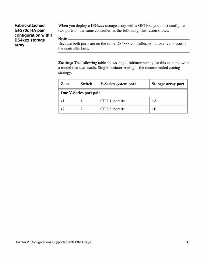
GF270c system with a DS4xxx storage array
When you deploy a DS4xxx storage array with a GF270c, you must configure two ports on the same controller (cluster) on the storage array, as the following illustration shows.
NoteBecause both ports are on the same controller, if the controller fails, no failover can occur.
Fabric-attached GF270c HA pair configuration with an ESS or a DS8xxx storage array
The following illustration shows a fabric-attached HA pair for a GF270c with an ESS or a DS8xxx storage array.
FC port
DS4xxx storagesubsystem
V-Series GF270c
FC port
Controller (cluster)
1A
1BLUNs 1-56
0C0C
Chapter 2: Configurations Supported with IBM Arrays 33

Zoning: The following table shows single-initiator zoning for this example with a model that uses cards. Single-initiator zoning is the recommended zoning strategy.
Zone Switch V-Series system port Storage array port
One V-Series port pair
z1 1 CPU 1, port 0c 1A
z2 2 CPU 2, port 0c 2A
Storagesubsystem
FC port
V-Series GF270c
FC port
Controller (cluster)
2A
Switch 2Switch 1
LUNs 1-561A
0C 0C
34 Configurations with a GF270c
Fabric-attached GF270c HA pair configuration with a DS4xxx storage array
When you deploy a DS4xxx storage array with a GF270c, you must configure two ports on the same controller, as the following illustration shows.
NoteBecause both ports are on the same DS4xxx controller, no failover can occur if the controller fails.
Zoning: The following table shows single-initiator zoning for this example with a model that uses cards. Single-initiator zoning is the recommended zoning strategy.
Zone Switch V-Series system port Storage array port
One V-Series port pair
z1 1 CPU 1, port 0c 1A
z2 2 CPU 2, port 0c 1B
Chapter 2: Configurations Supported with IBM Arrays 35

Fabric-attached configurations that optimize performance
Optimizing performance by using multiple LUN groups
This example shows a configuration that enables you to optimize performance by spreading the I/O across the parity group (array). You set up your configuration so that different port pairs on a V-Series system access different groups of LUNs on the storage array. The V-Series system sees each LUN over only two paths.
NoteThe V-Series Support Matrix is the final authority about which storage arrays and configurations that V-Series systems support.
On the storage array, different LUN groups are accessed through different ports. Each number used to identify a logical device must be unique on the same storage array, but numbers presented to hosts to identify LUNs (external numbers) can be duplicated on different ports.
AttentionStarting with 7.3, Data ONTAP adds functionality to support this configuration for DS8xxx and DS4xxx/DS5xxx storage arrays only. Prior to Data ONTAP 7.3, using multiple V-Series port pairs to access different LUN groups on the same storage array results in more than two paths to an array LUN which causes the system to not function properly.
Rules for implementing multiple LUN groups
To implement this type of configuration, you need to do the following:
◆ On the storage array, use as many ports as possible to provide access to the LUNs you allocated for V-Series.
◆ On the V-Series system, use multiple port pairs. Each port pair accesses a different group of LUNs on the storage array, using redundant paths.
◆ In the Data ONTAP configuration, create one large aggregate, assigning LUNs from multiple parity groups to the aggregate. By doing so, the I/O is spread across more disks.
The combination of spreading I/O across the parity group (array) and creating one large aggregate results in a significant performance boost.
36 Fabric-attached configurations that optimize performance

You can configure multiple LUN groups on DS4xxx, DS5xxx, and DS8xxx storage arrays. See “DS8xxx configuration with multiple LUN groups” on page 46 for information specific to DS8xxx storage arrays. See “DS4xxx/DS5xxx configuration with multiple LUN groups” on page 55 for information specific to DS4xxx/ DS5xxx storage arrays.
Stand-alone system The following illustration shows a configuration with a stand-alone V6xxx system. One V-Series port pair accesses LUNs in one LUN group on the storage array and a different V-Series port pair accesses LUNs in a different LUN group on the storage array.
Zoning for this configuration: The following table summarizes the zoning for this example. Single-initiator zoning is the recommended zoning strategy.
V-Series system
0a 0b 0c 0d 0e 0f 0g 0h
Storagesubsystem
Controller(cluster)
Controller(cluster)
2A1A LUNs 1-100
2B1B LUNs 101-200
Switch 1 Switch 2
Zone V-Series system FC initiator port Storage array port
Switch 1
z1 Port 0a Port 1B
z3 Port 0c Port 1A
Chapter 2: Configurations Supported with IBM Arrays 37

Switch 2
z2 Port 0h Port 2B
z4 Port 0f Port 2A
Zone V-Series system FC initiator port Storage array port
38 Fabric-attached configurations that optimize performance

HA pair configuration with two 4-port LUN groups
The following illustration shows an HA pair with V3xxx V-Series systems. On each V-Series system, two V-Series port pairs are used to optimize performance. The V-Series port pairs are as follows:
◆ 0a and 0c
◆ 0b and 0d
Each V-Series port pair accesses a separate device group on the storage array.
2B
1C
1D
vs1
0a 0b 0c 0d
vs2
0a 0b 0c 0d
2A1A
1B
2D
2C
Clusterinterconnect cables
Controller(cluster) 2
z1 z2z3 z4 z8z6z7z5
Switch 1 Switch 2
Fabric 1 Fabric 2
Storage array
Controller(cluster) 1
z1 z3
z2 z4
z5
z6
LUNs 1-10
LUNs 11-25 z8
z7
Chapter 2: Configurations Supported with IBM Arrays 39

The following table summarizes the zoning for this configuration.
Zone
V-Series system and port Storage array
Storage port LUN group
Switch 1
z1 vs1-0a Controller 1 1A LUNs 1 - 10
z2 vs2-0a Controller 1 1B LUNs 1 - 10
z5 vs1-0b Controller 1 1C LUNs 11 - 25
z6 vs2-0b Controller 1 1D LUNs 11 - 25
Switch 2
z3 vs1-0c Controller 2 2A LUNs 1 - 10
z4 vs2-0c Controller 2 2B LUNs 1 - 10
z7 vs1-0d Controller 2 2C LUNs 11 - 25
z8 vs2-0d Controller 2 2D LUNs 11 - 25
40 Fabric-attached configurations that optimize performance

Chapter 3: Configuring DS8xxx arrays
3
Configuring DS8xxx arraysAbout this chapter This chapter provides information about the requirements for setting up a DS8xxx storage array to work with V-Series, and an overview of the tasks you need to perform to configure LUNs on a DS8xxx storage array.
Topics in this chapter
This chapter contains the following topics:
◆ “DS8xxx configuration requirements” on page 42
◆ “DS8xxx configuration overview” on page 44
◆ “DS8xxx configuration with multiple LUN groups” on page 46
About Storage Manager
With the DS8000, the Storage Manager is a browser-based GUI that is part of the microcode. In contrast, with the DS4xxx/DS5xxx storage arrays, the GUI is provided through client software.
Volume group defined
A DS8xxx volume group is used to control the hosts that can access array LUNs (LUN masking) by associating host attachments or port groups with the array LUNs that they are allowed to access. You assign the desired FC initiator ports and the array LUNs to be accessed to the same volume group.
41

DS8xxx configuration requirements
Rules for the DS8xxx series
Use the following information to plan for configuring a DS8xxx storage array to work with a V-Series system.
NoteWhen a host type of Sun-Solaris is used, the DS8xxx logical volume IDs are in hexadecimal format. Data ONTAP LUN IDs are in decimal format. To correlate DS8xxx logical volumes to Data ONTAP LUNs, you must convert the hexadecimal numbers to decimal.
Recommended number of volume groups
For releases 7.3 and later: Use a single volume group for each LUN group on a DS8xxx storage array to guarantee the DS8xxx array LUNs are consistently presented to all V-Series system initiators that access them. If array LUNs are not consistently presented there is a potential for data corruption.
For releases prior to 7.3: Use a single volume group on a DS8xxx storage array.
For... Value...
Number of array LUNs on the DS8xxx storage array that can be allocated to V-Series systems
256 array LUNs per host group, regardless of the number of array LUNs that the V-Series system or DS8xxx supports. This is a V-Series limitation with DS8xxx storage arrays.
Maximum array LUN size The size of the LUNs that you can create on the storage array is limited by the maximum array LUN size that Data ONTAP supports. See “Guidelines for array LUN sizing” on page 7.
Host type Sun Solaris for array LUNs mapped to V-Series.
42 DS8xxx configuration requirements
Storage array LUN access with the DS8300 9A2 LPAR
When setting up the DS8300 9A2 LPAR (system logical partition) model to interact with V-Series systems, ensure that you set up access to each array LUN so that the redundant paths are both accessing the same LPAR.
Chapter 3: Configuring DS8xxx arrays 43
DS8xxx configuration overview
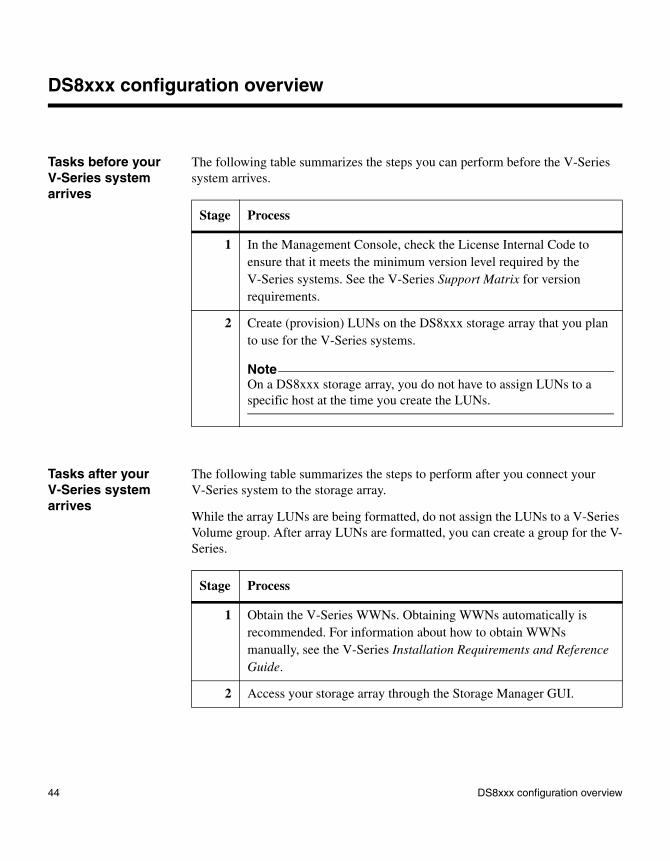
Tasks before your V-Series system arrives
The following table summarizes the steps you can perform before the V-Series system arrives.
Tasks after your V-Series system arrives
The following table summarizes the steps to perform after you connect your V-Series system to the storage array.
While the array LUNs are being formatted, do not assign the LUNs to a V-Series Volume group. After array LUNs are formatted, you can create a group for the V-Series.
Stage Process
1 In the Management Console, check the License Internal Code to ensure that it meets the minimum version level required by the V-Series systems. See the V-Series Support Matrix for version requirements.
2 Create (provision) LUNs on the DS8xxx storage array that you plan to use for the V-Series systems.
NoteOn a DS8xxx storage array, you do not have to assign LUNs to a specific host at the time you create the LUNs.
Stage Process
1 Obtain the V-Series WWNs. Obtaining WWNs automatically is recommended. For information about how to obtain WWNs manually, see the V-Series Installation Requirements and Reference Guide.
2 Access your storage array through the Storage Manager GUI.
44 DS8xxx configuration overview

3 Create a single volume group for all V-Series systems in the V-Series neighborhood so that all V-Series systems in the neighborhood can access the V-Series LUNs:
◆ Assign type SCSI map 256 to the V-Series volume group.
◆ Assign the LUNs that the V-Series systems share to the volume group (that is, the array LUNs that all V-Series systems in the V-Series neighborhood can see).
The name that you assign to the V-Series volume group should help you easily identify that the volume group is for V-Series systems.
NoteOn the DS8xxx, logical volume IDs (LUNs) are available on all ports by default. You do not have to map array LUNs to ports. A set of array LUNs is grouped into a single volume group of type SCSI map 256. Write down this volume group name and specify it when you create a host for each V-Series FC initiator port.
4 For a direct-attached configuration: When you create the Host Attachment files for the ports, change the default setting, which is FcSf (fibre-channel-switch-fabric). Set the Host Attachment Port type and Storage Image I/O port settings on the HBAs to FcAl (Fibre Channel Arbitrated Loop).
NoteIf you do not change the setting from FcSf to FcAL, direct attachment of the V-Series system does not work correctly.
5 Identify the WWN of each V-Series system FC initiator port, and assign the host type of Sun-Solaris to each.
6 (Optional) Specify port masking to restrict V-Series systems to certain ports.
Stage Process
Chapter 3: Configuring DS8xxx arrays 45

DS8xxx configuration with multiple LUN groups
Multiple LUN group requirements
The following are requirements to configure multiple LUN groups on DS8xxx storage arrays:
◆ Switch zoning must define which target ports the V-Series system FC initiator ports use to access each LUN group.
◆ Volume groups must define which LUN groups are presented to each V-Series system initiator port.
◆ One initiator port pair for each V-Series system is required for each LUN group.
46 DS8xxx configuration with multiple LUN groups

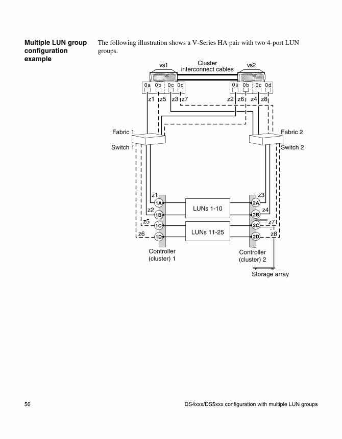
Multiple LUN group configuration example
The following illustration shows a V-Series system HA pair with two 4-port LUN groups on a on DS8xxx storage array.
2B
1C
1D
vs1
0a 0b 0c 0d
vs2
0a 0b 0c 0d
2A1A
1B
2D
2C
Clusterinterconnect cables
Controller(cluster) 2
z1 z2z3 z4 z8z6z7z5
Switch 1 Switch 2
Fabric 1 Fabric 2
Storage array
Controller(cluster) 1
z1 z3
z2 z4
z5
z6
LUNs 1-10
LUNs 11-25 z8
z7
Chapter 3: Configuring DS8xxx arrays 47

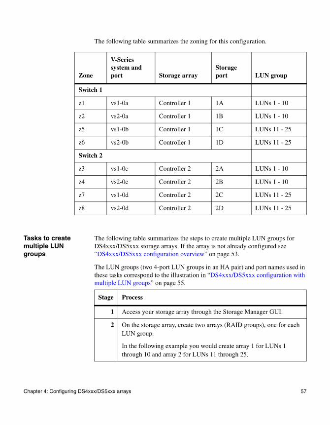
The following table summarizes the zoning for this configuration.
Tasks to create multiple LUN groups
The following table summarizes the steps to create multiple LUN groups on DS8xxx storage arrays. If the storage array is not already configured, see “DS8xxx configuration overview” on page 44.
The LUN groups (two 4-port LUN groups in an HA pair) and port names used in these tasks correspond to the “Multiple LUN group configuration example” on page 47.
Zone
V-Series system and port Storage array
Storage port LUN group
Switch 1
z1 vs1-0a Controller 1 1A LUNs 1 - 10
z2 vs2-0a Controller 1 1B LUNs 1 - 10
z5 vs1-0b Controller 1 1C LUNs 11 - 25
z6 vs2-0b Controller 1 1D LUNs 11 - 25
Switch 2
z3 vs1-0c Controller 2 2A LUNs 1 - 10
z4 vs2-0c Controller 2 2B LUNs 1 - 10
z7 vs1-0d Controller 2 2C LUNs 11 - 25
z8 vs2-0d Controller 2 2D LUNs 11 - 25
Stage Process
1 Access your storage array through the Storage Manager user interface.
2 On the storage array, create two extent pools, one for each LUN group.
In the example you would create extent pool 1 for LUNs 1 through 10 and extent pool 2 for LUNs 11 through 25.
48 DS8xxx configuration with multiple LUN groups

3 Create one set of volumes for extent pool 1 and a second set of volumes for extent pool 2.
4 Create one volume group with V-Series system FC initiator ports 0a and 0c from both V-Series systems and all the volumes from extent pool 2.
5 Create a second volume group with V-Series system FC initiator ports 0b and 0d from both V-Series systems and all the volumes from extent pool 1.
6 Configure the zoning of the switches so that each V-Series initiator port accesses only a single target port (as shown in the following illustration).
Stage Process
Chapter 3: Configuring DS8xxx arrays 49

50 DS8xxx configuration with multiple LUN groups

Chapter 4: Configuring DS4xxx/DS5xxx arrays
4
Configuring DS4xxx/DS5xxx arraysAbout this chapter This chapter provides information about the requirements for setting up DS4xxx/DS5xxx storage arrays to work with V-Series and an overview of the tasks you need to perform to configure LUNs on DS4xxx/DS5xxx storage arrays.
Topics in this chapter
This chapter discusses the following topics:
◆ “DS4xxx/DS5xxx configuration requirements” on page 52
◆ “DS4xxx/DS5xxx configuration overview” on page 53
◆ “DS4xxx/DS5xxx configuration with multiple LUN groups” on page 55
51

DS4xxx/DS5xxx configuration requirements
Rules for the DS4xxx series
Use the following information to plan for configuring all DS4xxx/DS5xxx series storage array models to work with a V-Series system.
For... Value...
Number of LUNs on the DS4xxx/DS5xxx that can be allocated to V-Series systems
256 LUNs per host group, regardless of the number of LUNs that the V-Series system supports. This is a V-Series limitation with DS4xxx/DS5xxx storage arrays.
Maximum array LUN size The size of the array LUNs that you can create on the storage array is limited by the maximum array LUN size that Data ONTAP supports. See “Guidelines for array LUN sizing” on page 7.
Host type AIX
52 DS4xxx/DS5xxx configuration requirements

DS4xxx/DS5xxx configuration overview
Prerequisites to configuration
Before continuing with this chapter, you should have already accomplished the following tasks:
◆ You allocated arrays for the V-Series systems before V-Series system installation and connection to the storage array.
Before you can create LUNs for V-Series systems, you must define an array on your storage array.
NoteIn the context of this chapter, “arrays” means RAID sets or parity groups. Array creation enables you to allocate space on the storage array.
◆ You created LUNs for the V-Series systems.
NoteIf you did not create arrays or LUNs for V-Series systems, see you must create them.
Task overview The following table summarizes the tasks to set up the storage array to work with the V-Series system.
NoteThe following processes take place on the storage array UI after you connect your V-Series system to your storage array. You must have the Storage Partitioning License to perform this process.
Stage Process
1 Obtain the V-Series WWNs. It is recommended that you obtain the WWNs automatically. For information about how to obtain the WWNs manually, see the V-Series Installation Requirements and Reference Guide.
2 Gain access to your storage array through the user interface.
3 Check the controller firmware version to ensure that it meets the minimum version level required by the V-Series system.
Chapter 4: Configuring DS4xxx/DS5xxx arrays 53

4 If... Then...
Array LUNs were created for the V-Series systems
Go to Step 5.
Array LUNs were not created for the V-Series systems but free capacity is available in any array
Create LUNs on the storage array by using available free space, then go to Step 5 in this overview.
Array LUNs were not created for V-Series systems and the capacity is unconfigured
Create LUNs on the storage array by using unconfigured free space. Then go to Step 5 in this overview.
5 Create a host group on the storage array. You add the FC initiator ports of the V-Series systems to the host group on the storage array to establish a logical connection for mapping LUNs. You must add to the host group the WWNs of all FC initiator ports of the V-Series systems that need to see the same LUNs (that is, all participants in the V-Series neighborhood).
Host type requirement: In the Storage Manager, when you add your V-Series system to a host group, you must select AIX as the host type of your V-Series system.
Before creating a host group:
◆ Ensure that the V-Series system FC initiator port WWPNs are available (see the V-Series Installation Requirements and Reference Guide).
◆ If LUNs have not yet been created on your storage array for the V-Series system, you must create the LUNs.
❖ If you have available free capacity, you must create new logical drives from available free capacity.
❖ If space is unconfigured, you must create arrays from unconfigured capacity.
6 Map the array LUNs to the V-Series system.
7 Add more arrays later, if needed.
Stage Process
54 DS4xxx/DS5xxx configuration overview

DS4xxx/DS5xxx configuration with multiple LUN groups
Multiple LUN group requirements
The following are requirements to configure multiple LUN groups on DS4xxx/DS5xxx storage arrays:
◆ Switch zoning must define which target ports the V-Series FC initiator ports use to access each LUN group.
◆ The host group must define which LUN groups are presented to each V-Series initiator port.
◆ One initiator port pair is required for each LUN group.
◆ All target ports on a controller accessing an individual LUN group must be accessed through the same switch.
Chapter 4: Configuring DS4xxx/DS5xxx arrays 55
Multiple LUN group configuration example
The following illustration shows a V-Series HA pair with two 4-port LUN groups.
2B
1C
1D
vs1
0a 0b 0c 0d
vs2
0a 0b 0c 0d
2A1A
1B
2D
2C
Clusterinterconnect cables
Controller(cluster) 2
z1 z2z3 z4 z8z6z7z5
Switch 1 Switch 2
Fabric 1 Fabric 2
Storage array
Controller(cluster) 1
z1 z3
z2 z4
z5
z6
LUNs 1-10
LUNs 11-25 z8
z7
56 DS4xxx/DS5xxx configuration with multiple LUN groups
The following table summarizes the zoning for this configuration.
Tasks to create multiple LUN groups
The following table summarizes the steps to create multiple LUN groups for DS4xxx/DS5xxx storage arrays. If the array is not already configured see “DS4xxx/DS5xxx configuration overview” on page 53.
The LUN groups (two 4-port LUN groups in an HA pair) and port names used in these tasks correspond to the illustration in “DS4xxx/DS5xxx configuration with multiple LUN groups” on page 55.
Zone
V-Series system and port Storage array
Storage port LUN group
Switch 1
z1 vs1-0a Controller 1 1A LUNs 1 - 10
z2 vs2-0a Controller 1 1B LUNs 1 - 10
z5 vs1-0b Controller 1 1C LUNs 11 - 25
z6 vs2-0b Controller 1 1D LUNs 11 - 25
Switch 2
z3 vs1-0c Controller 2 2A LUNs 1 - 10
z4 vs2-0c Controller 2 2B LUNs 1 - 10
z7 vs1-0d Controller 2 2C LUNs 11 - 25
z8 vs2-0d Controller 2 2D LUNs 11 - 25
Stage Process
1 Access your storage array through the Storage Manager GUI.
2 On the storage array, create two arrays (RAID groups), one for each LUN group.
In the following example you would create array 1 for LUNs 1 through 10 and array 2 for LUNs 11 through 25.
Chapter 4: Configuring DS4xxx/DS5xxx arrays 57

3 On the storage array, create a set of logical drives from array 1 and a second set of logical drives from array 2.
4 Create one host group with 0a, 0c from both V-Series systems and all the logical drives from array 1.
5 Create a second host group with 0b, 0d from both V-Series systems and all the logical drives from array 2.
6 Configure zoning on the switches so that each V-Series initiator port only accesses a single target port (as shown in the following illustration).
Stage Process
58 DS4xxx/DS5xxx configuration with multiple LUN groups

Chapter 5: Configuring ESS arrays
5
Configuring ESS arraysAbout this chapter This chapter provides information about the requirements for setting up an ESS storage array to work with the V-Series, and an overview of the tasks you need to perform to configure LUNs on an ESS storage array.
NoteThe V-Series Support Matrix is the final authority about which storage arrays and configurations that V-Series systems support.
Topics in this chapter
This chapter discusses the following topics:
◆ “ESS configuration requirements” on page 60
◆ “ESS configuration overview” on page 61
59
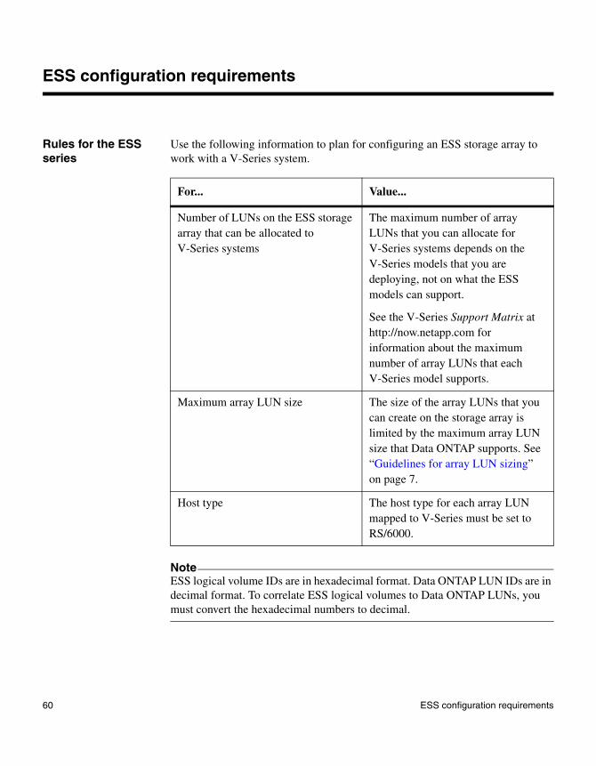
ESS configuration requirements
Rules for the ESS series
Use the following information to plan for configuring an ESS storage array to work with a V-Series system.
NoteESS logical volume IDs are in hexadecimal format. Data ONTAP LUN IDs are in decimal format. To correlate ESS logical volumes to Data ONTAP LUNs, you must convert the hexadecimal numbers to decimal.
For... Value...
Number of LUNs on the ESS storage array that can be allocated to V-Series systems
The maximum number of array LUNs that you can allocate for V-Series systems depends on the V-Series models that you are deploying, not on what the ESS models can support.
See the V-Series Support Matrix at http://now.netapp.com for information about the maximum number of array LUNs that each V-Series model supports.
Maximum array LUN size The size of the array LUNs that you can create on the storage array is limited by the maximum array LUN size that Data ONTAP supports. See “Guidelines for array LUN sizing” on page 7.
Host type The host type for each array LUN mapped to V-Series must be set to RS/6000.
60 ESS configuration requirements
ESS configuration overview
Tasks before your V-Series system arrives
The following table summarizes the steps you can perform before the V-Series system arrives.
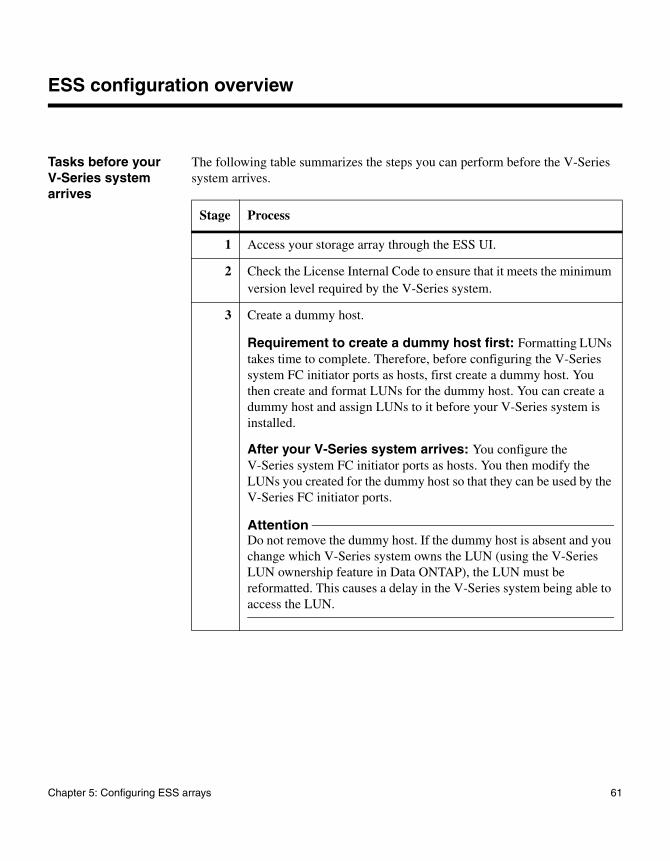
Stage Process
1 Access your storage array through the ESS UI.
2 Check the License Internal Code to ensure that it meets the minimum version level required by the V-Series system.
3 Create a dummy host.
Requirement to create a dummy host first: Formatting LUNs takes time to complete. Therefore, before configuring the V-Series system FC initiator ports as hosts, first create a dummy host. You then create and format LUNs for the dummy host. You can create a dummy host and assign LUNs to it before your V-Series system is installed.
After your V-Series system arrives: You configure the V-Series system FC initiator ports as hosts. You then modify the LUNs you created for the dummy host so that they can be used by the V-Series FC initiator ports.
AttentionDo not remove the dummy host. If the dummy host is absent and you change which V-Series system owns the LUN (using the V-Series LUN ownership feature in Data ONTAP), the LUN must be reformatted. This causes a delay in the V-Series system being able to access the LUN.
Chapter 5: Configuring ESS arrays 61

Tasks after your V-Series system arrives
The following table summarizes the steps to perform after you connect your V-Series system to the storage array.
4 Create LUNs for the dummy host.
When to create LUNs for the dummy host: You first create LUNs for the dummy host, then modify (remap) them to be used by the V-Series FC initiator ports.
AttentionAs new LUNs are created, ESS starts to format them. The V-Series system cannot recognize the LUNs while they are being formatted. Therefore, always assign (map) LUNs that you intend to use for the V-Series system to the dummy host first. After the LUN formatting finishes, remap the LUNs to the V-Series system’s FC initiator ports. Adding LUNs to the V-Series system’s FC initiator ports while the LUNs are being formatted can lead to data corruption.
Stage Process
Stage Process
1 Obtain the V-Series WWNs. It is recommended that you obtain WWNs automatically. For information about how to obtain WWNs manually, see the V-Series Installation Requirements and Reference Guide.
2 Access your storage array through the ESS UI.
3 Configure each V-Series system FC initiator port as a host.
Requirement for identifying V-Series ports: You must create a host in the ESS UI for each V-Series FC initiator port that you plan to connect to the storage array.
Prerequisite: Be sure that you have the WWN for each V-Series FC initiator port that you plan to connect to the storage array. If you do not have the V-Series system World Wide Names, see the V-Series Installation Requirements and Reference Guide.
62 ESS configuration overview

4 Configure host adapter ports on the storage array to establish port access to the array LUNs.
5 Modify LUN assignments (mappings) so that V-Series FC initiator ports can use the array LUNs.
You must reassign (remap) the array LUNs you assigned to the dummy host to the V-Series system’s FC initiator ports.
AttentionThe LUNs must be finished formatting before you modify the LUNs on the storage array, or data corruption can occur.
Stage Process
Chapter 5: Configuring ESS arrays 63

64 ESS configuration overview
Appendix A: DS4xxx firmware upgrade issue workaround
A
DS4xxx firmware upgrade issue workaroundAbout this appendix This appendix describes how to workaround a DS4xxx firmware upgrade issue.
Topics in this appendix
This appendix discusses the following topics:
◆ “Description of the issue” on page 65
◆ “Requirement when performing the workaround on a production system” on page 66
◆ “Effect of the workaround on communication with AIX” on page 66
◆ “Running a script to restore V-Series compatibility” on page 66
◆ “Reverting after the workaround is applied” on page 68
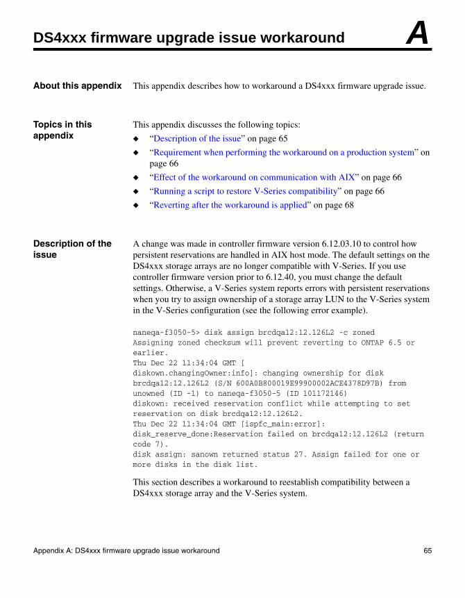
Description of the issue
A change was made in controller firmware version 6.12.03.10 to control how persistent reservations are handled in AIX host mode. The default settings on the DS4xxx storage arrays are no longer compatible with V-Series. If you use controller firmware version prior to 6.12.40, you must change the default settings. Otherwise, a V-Series system reports errors with persistent reservations when you try to assign ownership of a storage array LUN to the V-Series system in the V-Series configuration (see the following error example).
naneqa-f3050-5> disk assign brcdqa12:12.126L2 -c zoned Assigning zoned checksum will prevent reverting to ONTAP 6.5 or earlier. Thu Dec 22 11:34:04 GMT [diskown.changingOwner:info]: changing ownership for disk brcdqa12:12.126L2 (S/N 600A0B800019E99900002ACE4378D97B) from unowned (ID -1) to naneqa-f3050-5 (ID 101172146) diskown: received reservation conflict while attempting to set reservation on disk brcdqa12:12.126L2. Thu Dec 22 11:34:04 GMT [ispfc_main:error]: disk_reserve_done:Reservation failed on brcdqa12:12.126L2 (return code 7). disk assign: sanown returned status 27. Assign failed for one or more disks in the disk list.
This section describes a workaround to reestablish compatibility between a DS4xxx storage array and the V-Series system.
65

Requirement when performing the workaround on a production system
You can perform this workaround on a storage array that is in production.
Effect of the workaround on communication with AIX
Performing this workaround affects all hosts connected to the storage array as type AIX if the host is running an application that uses SCSI-3 reservations (for example, VERITAS DMP). No effect has been observed with AIX running Tivoli® Storage Manager (TSM).
Running a script to restore V-Series compatibility
To reestablish compatibility between the DS4xxx storage array and the V-Series system, complete the following steps.
NoteThe option changed by this workaround is 0x27, bit 3, which is the type of parameter data that is returned in response to a prin command with a read reservation service action. The bit 3 = 0 A header is returned with a reservation key set to zero. This behavior is not is in accordance with the current T10 standards for the persistent reservations command set. However, it preserves compatibility with the legacy implementation. The bit 3 = 1 A header is returned (but no reservation key). This behavior is in accordance with the current T10 standards for the persistent reservations command set.
Step Action
1 In the IBM Storage Manager management software, right-click the storage array name in the left window pane, then select Execute Script from the drop-down menu.
66 DS4xxx firmware upgrade issue workaround

Example of a Host Type Index: The following example output shows the Host Type Index with “AIX” mapped to a Host Index of 6.
2 Enter the following in the top window of the script editor, which appears after you select Execute Script. Ensure that you enter AIX as the host type:
show controller[a] HOSTNVSRAMByte[“AIX”, 0x27]; show controller[b] HOSTNVSRAMByte["AIX", 0x27];
set controller[a] hostnvsrambyte["AIX",0x27]=0x8,0xff; set controller[b] hostnvsrambyte["AIX",0x27]=0x8,0xff;
show controller[a] HOSTNVSRAMByte["AIX", 0x27]; show controller[b] HOSTNVSRAMByte["AIX", 0x27];
The script output at the bottom of the screen shows the old settings, sets bit 3 of byte 0x27 of host mode AIX, then displays the new settings:show controller[a] HOSTNVSRAMByte["AIX", 0x27]; show controller[b] HOSTNVSRAMByte["AIX", 0x27]; set controller[a] hostnvsrambyte["AIX",0x27]=0x8,0xff; set controller[b] hostnvsrambyte["AIX",0x27]=0x8,0xff; show controller[a] HOSTNVSRAMByte["AIX", 0x27]; show controller[b] HOSTNVSRAMByte["AIX", 0x27]; Performing syntax check...Syntax check complete.Executing script...Controller "a" Host Type Index 6 NVSRAM offset 0x27 = 0x1.Controller "b" Host Type Index 6 NVSRAM offset 0x27 = 0x1.Controller "a" Host Type Index 6 NVSRAM offset 0x27 = 0x9.Controller "b" Host Type Index 6 NVSRAM offset 0x27 = 0x9.Script execution complete.
3 Look at the script output to verify that the script output shows the new value of 0x9:
◆ If the script output shows 0x9, the system should be in a V-Series compatible mode.
◆ If the script output does not show 0x9, reenter the text in the script, ensuring that the text that you enter in the script exactly matches Step 2.
4 View the NVSRAM Host Type Index to verify that AIX is mapped to one Index entry.
The Host Type Index is part of the storage array profile output. To access the storage array profile, from the Subsystem Management window, select Storage Subsystem > View Profile or Storage Subsystem > View > Profile (depending on your storage array type).
“Example of a Host Type Index” on page 67 shows an example of a Host Type Index that includes AIX as one entry.
Step Action
Appendix A: DS4xxx firmware upgrade issue workaround 67

NoteThe value of AIX in the Host Type Index on your system might be a value other than 6, which is shown in the following example. The mapping of host types to indexes varies for different storage array types.
Reverting after the workaround is applied
If a problem occurs and you need to revert, complete the following steps to disable the option that was set by the workaround.
INDEX ADT STATUS TYPE
0 Disabled Windows NT Non-Clustered (SP5 or higher)
1 Disabled Windows NT Clustered (SP5 or higher)
2 Disabled Windows 2000/Server 2003 Non-Clustered
3 Disabled Windows 2000/Server 2003 Clustered
4 Enabled NetWare-IBMSAN
5 Enabled Linux
6 (Default) Disabled AIX
7 Enabled HP-UX
8 Disabled Solaris
9 Enabled Windows 2000/Server 2003 Non-Clustered (supports DMP)
10 Disabled Irix
11 Enabled Netware Failover
12 Enabled IBM TS SAN VCE
13 Disabled LNXCL
14 Enabled Solaris (with Veritas DMP)
15 Enabled Windows 2000/Server 2003 Clustered (supports DMP)
Step Action
1 In the Storage Manager, right click the storage array name in the left window pane, then select Execute Script from the drop-down menu.
68 DS4xxx firmware upgrade issue workaround

2 Enter the following in the top window of the script editor, which appears after you select Execute Script.
NoteEnsure that you enter AIX as the host type.
set controller[a] hostnvsrambyte["AIX",0x27]=0x8,0x00; set controller[b] hostnvsrambyte["AIX",0x27]=0x8,0x00;
Step Action
Appendix A: DS4xxx firmware upgrade issue workaround 69

70 DS4xxx firmware upgrade issue workaround

Index
Cconfigurations
direct-attached HA pair 16, 32, 33fabric-attached HA pair 18fabric-attached stand-alone 18
DDS4xxx storage arrays
configuring for V-Series use 51firmware upgrade workaround 65host type required 52live upgrade is unsupported 6maximum LUNs supported 52rules for V-Series systems 52
DS5xxx storage arraysconfiguring for V-Series use 51host type required 52maximum LUNs supported 52rules for V-Series systems 52
DS8300 9A2 LPAR storage arrayspath setup with 43support for 5
DS8xxx storage arraysconfiguring for V-Series use 41configuring storage for V-Series use 59DS8300 9A2 LPAR, path setup with 43logical volume IDs 42maximum number of LUNs supported 42rules for V-Series systems 42, 46, 47, 49
dummy hostcaution about removing 61why needed 61
EESS storage arrays
dummy host fordo not remove 61why needed 61
logical volume IDs 60maximum number of LUNs supported 60
rules for V-Series systems 60
Ffabric-attached configuration
examples 18, 19, 33zoning 19, 21, 22, 24, 27, 29, 31
family, defined 4firmware on IBM storage arrays 6
GGF270c, configuration examples 32gigabyte, defined 7
HHA pair
direct-attached example 16, 32fabric-attached example 19, 25, 28, 33, 35
host typeDS4xxx storage arrays 52DS5xxx storage arrays 52DS8xxx storage arrays 42
Llicense versions on IBM platforms 6logical unit number, defined 1LUNs (array)
defined 1LUN size restriction 42, 52, 60security 10sizing guidelines 7
Mmultiple LUN groups
DS8xxx 48
Ooptimizing performance
Index 71
configuration example 36
Ppaths to array LUNs, number supported 12performance optimization
configuration example 36
Rredundant paths to an array LUN 12
Ssecurity for LUNs, requirements 10supported storage arrays 4
Tterminology
Data ONTAP 1
Vvolume group
defined 3, 41recommended number 42
volumes (Data ONTAP), defined 3volumes (IBM), defined 3
Zzoning
fabric-attached HA pair 21, 22, 24, 27, 29, 31fabric-attached stand-alone configuration 19recommendations for 18
72 Index