uwaft_electrical_ecocar2_y3
TRANSCRIPT
Electrical PresentationJordan Morris (MASc)
Eric Evenchick (BASc)

UWAFT Vehicle Powertrain
2.4 L LE9
E85
GK
N 9
.59
:1
Battery
Charger
Fuel
Tank
TM4 105 kW
Motor (Front)
A123 18.9 kWh
ESS
TM4 105 kW
Motor (Rear)
GK
N 7
.47
:1
TM4 105 kW
Generator
2:1
Be
lt D
rive
Electric Hybrid
Mechanical
ConnectionElectrical
Connection
Single-Speed
Gear ReductionFuel
Connection
Legend
Component Specification
Engine: GM
2.4L LE9 Flex
Fuel
Peak
Efficiency37%
Peak Power131 kW @
5800 rpm
Peak Torque230 Nm @
5000 rpm
ESS: A123
Systems Inc.
7 Module,
15s3p
Voltage 340 V
Energy 18.9 KWh
Peak Power 177 kW
Motor/
Generator:
TM4 MOTIVE
Peak/Cont.
Power105 – 54 kW
Peak/ Cont.
Torque180 – 70 Nm
Voltage
Range320 – 450 V
Final Drives:
GKN Driveline
Front Ratio 7.47:1
Rear Ratio 9.59:1
Charger:
Brusa NL513
Peak Power 3.3 kW
Typical
Efficiency93%

UWAFT VTS
Metric Design Target Requirement Actual
0-60mph (s) 9.5 11.5 6.8
50-70mph (s) 8.0 10 3.1
Top Speed (km/h) NA 120 151
60-0mph (m) 43.7 54.8 50
Vehicle Mass (kg) <2250 2250 2078
Vehicle Range (km) 322 322 400
EV Range (km) NA NA 42
Fuel Consumption (L/100km) 7.12 NA 4.34
WTW GTG Emissions (g GHG/km) 204 NA 169.3
Criteria Emissions T2 B5 T2 B5 T2 B5

General Fuse/Wire SelectionFuse Selection Considerations:
• Nominal Operating Current• Ambient Temperature• Overload Conditions and Opening
Times• Available Short Circuit Current• Melting Integral• Pulse and Inrush Characteristics• Characteristics of Protected Equipment• Physical Size• Standard Requirements
Wire Selection Considerations:
• Ensure wires are compatible with SAE J1127 and J1128 standard
• Peak Current Draw• Wire Length• Ambient Temperature
Wire Margins:
In General: Fuse is selected based on component characteristicsWire is selected based on fuse characteristics
• For LV systems:• For HV system cables selected
based on manufacturer recommendations

Fuse De-Rating Example (Generator)
Fuse De-Rating Calculations
• Typical under hood temperature can reach 100OC• Inside distribution box can reach 60OC• for motor is 169A
Derating Factor Symbol Value
Max Permissible Current 𝐼𝑏 180
Rated Current for Given Fuse 𝐼𝑛 225
Ambient Temperature 𝑘𝑇 0.8
Thermal Correction Factor 𝑘𝑒 ~1
Cooling Air Correction Factor 𝑘𝑣 1
Frequency Correction Factor 𝑘𝑓 ~1
Correction for High Altitude 𝑘𝑎 1

I2T Analysis Front Cooling Loop• Includes pump and fan• Fuse Rating = 20 A• Lightning pulse characteristic• Melting I2T = 520 A2S• Pulse I2T = 227.40768• Based on these calculations fuse was replaced
with 25 A fuse to limit nuisance fuse blows

ComponentPulse Peak
(A)0.5t (s) I2T
Rated Fuse (A) Melting I2T
% of Melting Condition
Fuse cycle Life1
Generator 12V 1 0.3 0.216 10 115 0.19 >100,000
Front Motor 12V 1 0.3 0.216 10 115 0.19 >100,000
Rear Motor 12V 1 0.3 0.216 10 115 0.19 >100,000
Front Cooling Loop 28.1 0.4 227.407 25 1080 21.06 >100,000
Clutch 15 0.2 32.4 15 340 9.53 >100,000
AC Compressor 12V 9 0.15 8.748 10 115 7.61 >100,000
BMS 12V 9.5 0.5 32.49 15 340 9.56 >100,000
Rear Cooling Loop 22 0.35 121.968 20 520 23.46 10k - 100k
DCDC Fan 4 0.2 2.304 5 26 8.86 >100,000DCDC LV Side N/A N/A N/A N/A N/A N/A N/A
GKN Park Lock 35 0.25 220.5 30 1510 14.60 >100,000
HVIL Supply 1.5 0.5 0.81 5 26 3.12 >100,000Dampers 3 0.15 0.972 5 26 3.74 >100,000
Fuse Cycle Life UWAFT Added Components
1. http://www.littelfuse.com/~/media/electronics/product_catalogs/littelfuse_fuse_catalog.pdf.pdf page 15

Load Accommodation and EfficiencyLoad Type Peak (UWAFT added) Load (A)
Nominal LV Load 52
Nominal LV Load with PHCC 152
Peak LV Load 113
Peak LV Load with PHCC 233
• GM APM connects 18.9 kWh HV battery to 480 Wh LV battery
• Additional loads are only activated when required• Pre-heated catalytic converter runs
less than 5 minutes

LV Parasitic Current
• Stock GM system has low parasitic draw, but must crank engine• UWAFT has higher current draw, but no LV engine crank• Why so high? Still running rapid prototyping tools
• For production remove controllers and development tools
System Stock UWAFT
Parasitic Current Draw (mA) 50 200
2 week Energy Drain (Ah) 16.8 67.2
12V Battery Capacity (Ah) 40 40
Vehicle No-Start Battery Voltage (V)
10.5 9.5
Time to No Start (weeks) 4.75 1.2

HV Bus Voltage/Current Ripple• Portion of drive cycle, stop and go traffic with CAN data• Max speed = 60 km/h• Max battery current = 115 A• Max battery power = 38 kW

HV Bus Voltage/Current Ripple: 40s window
MeasuredParameter
Sampling Rate
Peak-to-peakripple
Voltage 100 kHz 1
Current 10 kHz 8
Battery Current Draw
Battery Voltage
• Voltage measurements taken with ETAS HV sensors connected to HV Test port in rear distribution box
• Current measurements taken with hall effect sensor connected to ETAS LV sensors
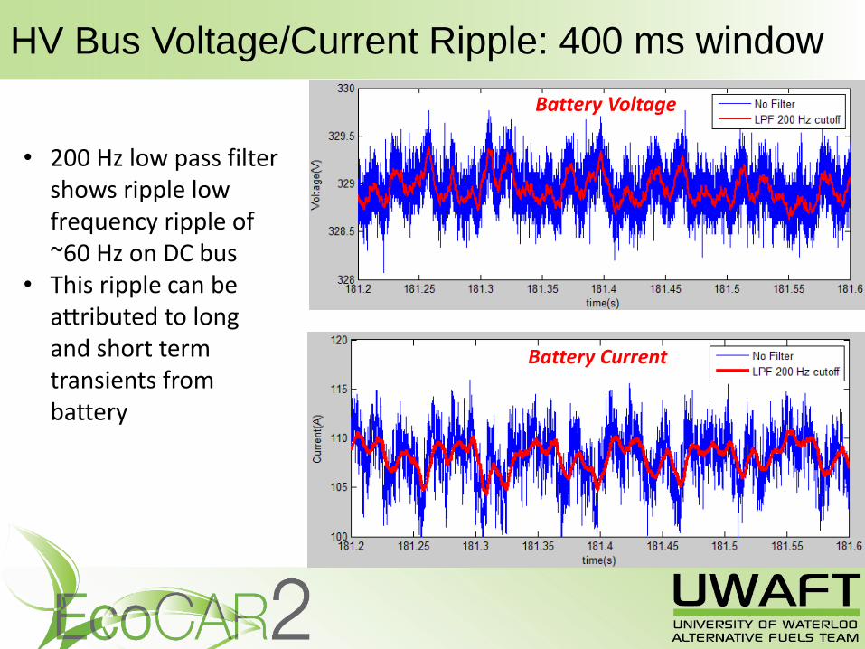
HV Bus Voltage/Current Ripple: 400 ms window
• 200 Hz low pass filter shows ripple low frequency ripple of ~60 Hz on DC bus
• This ripple can be attributed to long and short term transients from battery
Battery Voltage
Battery Current
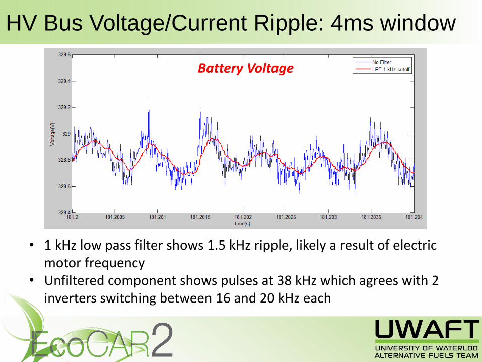
HV Bus Voltage/Current Ripple: 4ms window
• 1 kHz low pass filter shows 1.5 kHz ripple, likely a result of electric motor frequency
• Unfiltered component shows pulses at 38 kHz which agrees with 2 inverters switching between 16 and 20 kHz each
Battery Voltage
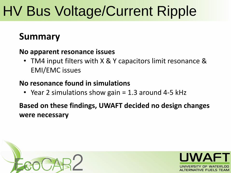
HV Bus Voltage/Current Ripple
Summary
No apparent resonance issues• TM4 input filters with X & Y capacitors limit resonance &
EMI/EMC issues
No resonance found in simulations• Year 2 simulations show gain = 1.3 around 4-5 kHz
Based on these findings, UWAFT decided no design changes were necessary

HV Bus Charge and Discharge Times
HV Bus Charge
HV Bus Discharge
• No engine start: motors are readily available, key-on to start time < 2 seconds
• At key off contactors opens and TM4 inverters discharge HV bus
• Bus capacitance = 1.875 mF

HV Safety and ServiceabilityE-Stops LED Indicators
HV Warning Labels
Safe Vehicle Servicing

HV Safety and Serviceability: Fault Detection

Challenge: Cable Routing
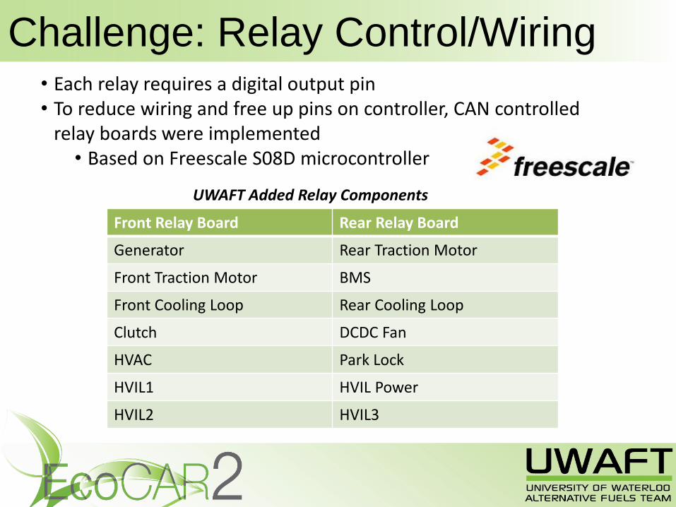
Challenge: Relay Control/Wiring
Front Relay Board Rear Relay Board
Generator Rear Traction Motor
Front Traction Motor BMS
Front Cooling Loop Rear Cooling Loop
Clutch DCDC Fan
HVAC Park Lock
HVIL1 HVIL Power
HVIL2 HVIL3
• Each relay requires a digital output pin• To reduce wiring and free up pins on controller, CAN controlled
relay boards were implemented• Based on Freescale S08D microcontroller
UWAFT Added Relay Components

Knowledge Transfer
Access to ToolsPartnership with Altium. Provides on-demand licenses for UWAFT team members
Central Repository New students can access all EcoCAR and EcoCAR2 documents
Mentorship Program Pairs new students with senior members
Safety TrainingAll students get basic high-voltage training before working on the car

QUESTIONS