uvm-systemc based hardware in the loop simulations for ... · it also speeds up root cause analysis...
TRANSCRIPT

1
UVM-SystemC based hardware in the loop
simulations for accelerated Co-Verification
Paul Ehrlich1, Thang Nguyen
2, Thilo Vörtler
3
1,3Fraunhofer IIS - Design Automation Division - EAS,
Dresden, Germany ({paul.ehrlich,thilo.voertler}@eas.iis.fraunhofer.de)
2Infineon Technologies Austria AG,
Villach, Austria ([email protected])
Abstract— Stricter and higher safety requirements at a higher cost-efficiency together with the tremendous
growth in the silicon integration capability in recent years have pushed automotive electronic systems to a safe
system-on-chip architecture approach. This is especially true for a modern airbag system application, which is a
safety critical heterogeneous mixed-signal real-time system. As a consequence, verification of those systems is
becoming an increasingly time consuming and costly task, which cannot be handled by a classical simulation-based
development flow anymore. System emulation, as well as hardware in the loop (HIL) techniques for system
integration and test are widely used by Tier-1 and OEMs and more recently are also accepted by Tier-2 suppliers.
Despite this, an in-efficiency on the link between simulation-based development and HIL/Emulation based
development still exists, especially on the interchangeability of test descriptions between both steps. To overcome this
we propose to run UVM-SystemC on HIL systems, allowing them to re-use the verification environment with its test
benches. This re-use enables a tight relationship between the computer based verification and the HIL based lab
validation and therefore helps to reduce the time of a redesign cycle. It also speeds up root cause analysis in the case
of bug findings during the lab validation. To realize the proposed strategy, different established methods and
techniques are combined, which will be illustrated within this paper on the basis of an industrial airbag system
application.
Keywords— UVM, Verification, Validation, Co-Verification, Verification re-use, UVM-SystemC, Hardware
Acceleration, SystemC-AMS, HIL, RCP, SoC
I. INTRODUCTION
Electronic System Level (ESL) design has become a mature and proven practice during the design of complex
embedded systems. It assists the engineers and system architects with various methodologies to create virtual
prototypes. SystemC [1] and SystemC-AMS [2] as system level modeling language for digital and analog hard-
and software as well as the transaction level modeling (TLM) as a communication abstraction methodology
thereby provide the basis to create lightweight and fast models needed to handle the increasing system size and
heterogeneity. Coupling such a system model with an advanced test bench methodology like UVM [3] enables
extensive verification activity, aimed at the specification and furthermore the application context. Especially the
newly introduced UVM-SystemC provides a methodology to extend the already SystemC based system level
designs with a test environment [4]. Nevertheless, those setups often require a high computational effort for a
classical simulation which can take hours or even up to a day. This is especially true for simulations of a mixed
abstraction based device under test (DUT) especially if it includes RTL descriptions within the system model and
thus the simulation based setup alone becomes impractical.
Rapid control prototyping (RCP) on the other hand is known and proven for the lab validation of real
hardware as well as their prototypical implementations at a very high speed, ideally real-time. Therefore the use
of HIL simulations promises relief and acceleration if coupled with the verification process, since the DUT or
parts of it are replaced from the virtual system with real hardware.
To effectively use the HIL simulations to aid the verification and therefore the whole system level design
process, a tight coupling between the verification of the virtual prototype and lab validation of the DUT with the
HIL has to be established. The paper therefore presents a novel strategy (shown in Figure 1) to enable the re-use
of the test environment, with its test and check sequences throughout verification and lab validation activities.
This allows a bigger iterative loop between those two steps (shown in Figure 1), whereby an early move of the
implementation onto the prototype can accelerate and aid the verification, because of the speed supremacy of the

2
validation task. It shortens the time of a root-cause analysis in the virtual prototype through the re-use of the test
sequences obtained from the HIL simulation within the computer based verification. Including the HIL in the
verification process also has the noticeable side effect of not only increasing the speed but also the bug detection
possibilities at an early point in time to reduce development costs.
Figure 1 Verification and lab validation overview including DUT evolution.
The paper is organized as follows: The second section describes the proposed methodology with its
advantages. The third section describes the flow integration exemplarily in case of an existing SystemC/SystemC-
AMS integrated development environment (IDE). Then in section four, a case study based on the airbag SoC is
shown. Finally, section five concludes the paper and gives an outlook on future topics.
II. PROPOSSED METHODOLOGY
As mentioned in the introduction the whole setup contains a DUT and an attached test environment (shown in
Figure 1). During the design process time elapses from the left to the right during which the testing can be
distinguished in two tasks: a verifying task done on the models to check their requirement fulfillment and a
validating task to prove that they are implemented correctly.
A. DUT development
During the design process, the DUT evolves from a behavioral SystemC-AMS description to a mixed
abstraction model. In this second stage parts are replaced by more detailed RTL descriptions based on
Verilog/VHDL, while other parts especially analog ones remain in SystemC-AMS or get mixed with behavior
descriptions of analogue circuits using the VHDL real value modeling technique [5]. In a classical model-based
development environment, these two DUT models are normally used for proof-of-concept and to support the
development, including the debugging, of test cases, test bench and the test sequences. After reaching a certain
verification coverage, the mixed-abstraction model can be synthesized towards an FPGA prototype coupled to
risk-minimizing analog test chips to build up the first hardware setup [6]. The transition from the software based
model to the first hardware implementation thereby defines the boundary between the above mentioned
verification and validation step. In the final development step all parts move together in a single SoC – so-called
DUT Silicon ASIC.
B. Test environment
While the DUT evolves during the design process the test environment should remain as similar as possible to
guarantee functional correct testing throughout the steps. This constancy also ensures that a minimal effort is
spend on test environment creation and its porting from the software implementation to the one of HIL-Tester and
vice versa. Figure 2 illustrates the soft- and hardware layers of the verification and lab validation architecture and
emphasizes the proposed re-use of the described novel strategy
As depicted the test environment is based on UVM-SystemC represented by the three upper most layers. In it
the high abstraction test description provides test vectors to the specific UVM agent via the virtual sequencer,
which in turn provide specific driver and monitor components (not shown) to connect the test environment to the
Design Sign-Off
HIL basedTester
DU
T
Imple
menta
tions
DUTMixed
Abstraction
DUTSystemC
(behavioral)
DUT-FPGA Prototype
DUT-ASIC Silicon
Simulation based Environment
UVM-SystemC Environment
re-use
MonitorDriver
UVM-SystemCEnvironment
MonitorDriver
Lab ValidationVerification
Test
Environm
ent
Abstraction level

3
corresponding DUT implementation. During the verification the monitor and drivers are function
implementations, connecting and wrapping the modeled DUT via Interfaces to the UVM-SystemC test
environment. Whereas the connection in case of the validation requires some more attention since it has to
connect trough specific hardware of the HIL-Tester, e.g. a FPGA providing SPI functionality. Requirements for
those HIL-Testers and two possible platforms are discussed in sections 1) and 2) below. The final hardware
namely the ASIC SoC has the most constrained interface due to its limited number of hardware pins. It therefore
defines the minimal interface to the test environment, used to enable the proposed re-use of test sequences with its
vectors throughout the process. This is also emphasized in Figure 2 where the corresponding two components
span over the scenarios layers covering the different design steps.
Figure 2 Detailed view on the soft- and hardware implementation highlighting the re-use of the proposed novel strategy.
1) HIL Tester
The so called HIL-Tester represents a hardware system with its corresponding software tool chain, capable of
building and running directly the UVM-SystemC based test environment, wherefore it has to fulfill the following
requirements:
A fully compatible C++ Compiler, to compile SystemC and corresponding UVM-SystemC and SystemC-
AMS libraries
A Hardware interface to connect the DUT (GPIOs, SPIs, ADCs, DACs, …)
A high-performance processing system capable of running the test environment at sufficient speed, ideally
at real-time
Predictable timing behavior to generate DUT stimuli at a specified timing
2) Example HIL-Tester
The above criteria led to the following two test environments. The first one is based on a dSPACE box with a
DS1006 processor board [8] running the UVM-SystemC environment almost on bare metal by wrapping it with
an initialize call and a background task called periodically. The second one is an ARM based Zynq-SoC [9], build
on the cost-effective Zedboard [10], running a real-time Linux scheduling the test environment. Both were able to
Lab Validation
X86-Computer
DUT FPGA or
ASIC-Silicon
HIL- System
Real-Time
OS
Hardware SPI
on FPGA
UVM_SC_Agent(HIL)
Verification
X86 / 64 - System
Windows/Linux OS
DUT Mixed AbstractionInterfaces
UVM_SC_Agent(SIM)
DUT SC-AMS BehaviorInterfaces
UVM_SC_AGent(SIM)FUNC/CM
D
Layer
Test bench with virtual sequencer
SystemC-AMS high-abstraction Test Description
ScenarioLayer
Application
Layer
Signal Layer
UVM Layer
Soft- and HardwarePlattform

4
fulfill the requirements enabling the native run of the UVM-SystemC environment. For the case study described
in section IV the latter was used.
C. Advantages
To illustrate the advantages of the proposed methodology it will be presented with the help of the Swiss
Cheese Model as depicted in Figure 3. Widely used in quality management, the analogy of the Swiss Cheese
Model describes the escape of possible errors/bugs for each used tools/methodologies due to their limitation.
Therefore, it’s important to combine different tools and methodologies so that more bugs can be captured, hence
improving the design quality. As shown in Figure 3, the upper layer represents the computer based simulation
whereas the lower layer represents the lab validation.
It’s essential to deploy computer based simulation at the beginning until it reaches certain coverage and then
continue with the HIL-testing with physical prototyping. With the prototype, it allows accelerated verification
runs as well as extremely high speed validation tests with real time stimuli generation. This is a clear advantage
compared to classical mixed-signal simulation approaches, as it overcomes their bottle neck due to its simulation
performance issues. With the newly proposed methodology and the resulting speed, also randomized tests are
possible. The higher test coverage gained by the lab validation is depicted in the cheese model by the smaller
number and lesser size of holes in the lower layer, whereas the remaining holes e.g. can be seen as test scenarios
not achievable due to the lack of access to internal DUT signals.
As the test sequences are re-used, including the test vectors, a direct mapping between the verification and
validation activities gets possible. Any detected errors in one or the other layer can quickly reveal inconsistencies
in the DUT and can single out bugs that were otherwise missed at this stage. In the cheese each test vector is
represented by a bug dropping down on a straight line, which represents the re-use in the beneath layer.
Root cause analysis on the other hand are more focused, and thus require less effort and time, whereby also
the re-implementation and testing of the bug-fixes is accelerated, since the test vector can specifically re-use in
the layer above to direct the DUT into the detected error state.
Additionally to the advantages of the methodology illustrated with the Swiss cheese an early FPGA prototype
can be provided with it at a minimum effort. This is due to the early integration of RTL code in the DUT. The
complete implementation of certain important functions of the chip can thus be validated before the final chip is
assembled and produced.
Therefore, the overall advantage of the re-use and thus increased test coverage and speed, is the increased
detection of errors vastly reducing development costs.
Figure 3 Swiss-cheese model for verification / validation process.
5
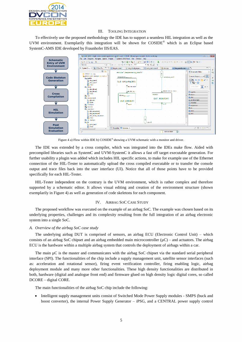
III. TOOLING INTEGRATION
To effectively use the proposed methodology the IDE has to support a seamless HIL integration as well as the
UVM environment. Exemplarily this integration will be shown for COSIDE® which is an Eclipse based
SystemC-AMS IDE developed by Fraunhofer IIS/EAS.
Figure 4 a) Flow within IDE b) COSIDE® showing a UVM schematic with a monitor and driver.
The IDE was extended by a cross compiler, which was integrated into the IDEs make flow. Aided with
precompiled libraries such as SystemC and UVM-SystemC it allows a fast off target executable generation. For
further usability a plugin was added which includes HIL specific actions, to make for example use of the Ethernet
connection of the HIL-Tester to automatically upload the cross compiled executable or to transfer the console
output and trace files back into the user interface (UI). Notice that all of those points have to be provided
specifically for each HIL-Tester.
HIL-Tester independent on the contrary is the UVM environment, which is rather complex and therefore
supported by a schematic editor. It allows visual editing and creation of the environment structure (shown
exemplarily in Figure 4) as well as generation of code skeletons for each component.
IV. AIRBAG SOC CASE STUDY
The proposed workflow was executed on the example of an airbag SoC. The example was chosen based on its
underlying properties, challenges and its complexity resulting from the full integration of an airbag electronic
system into a single SoC.
A. Overview of the airbag SoC case study
The underlying airbag DUT is comprised of sensors, an airbag ECU (Electronic Control Unit) – which
consists of an airbag SoC chipset and an airbag embedded main microcontroller (µC) – and actuators. The airbag
ECU is the hardware within a multiple airbag system that controls the deployment of airbags within a car.
The main µC is the master and communicates with the airbag SoC chipset via the standard serial peripheral
interface (SPI). The functionalities of the chip include a supply management unit, satellite sensor interfaces (such
as: acceleration and rotational sensor), firing event verification controller, firing enabling logic, airbag
deployment module and many more other functionalities. These high density functionalities are distributed in
both, hardware (digital and analogue front end) and firmware glued on high density logic digital cores, so called
DCORE – digital CORE.
The main functionalities of the airbag SoC chip include the following:
Intelligent supply management units consist of Switched Mode Power Supply modules - SMPS (buck and
boost converter), the internal Power Supply Generator – iPSG, and a CENTRAL power supply control
Code Skeleton Generation
Schematic Entry of UVM Environment
Cross Compilation
HIL Simulation
Post Simulation Evaluation

6
logic, which controls the chip power up and power down stage and monitors the system supply integrity. It
also provides logic for failsafe state diagnostics in case of integrity violation.
Remote sensor interfaces supporting different sensor types ranging from acceleration to rotational sensors
and compliance to various standards such as PSI5 (Peripheral Sensor Interface) [7] or DSI3 (Distributed
System Interface) [6]
Saving engine assisting the main µC in observing the sensor data transmission and confirming if a
deployment event has occurred.
Airbag deployment module – squib drivers and deployment enabling logic – allowing current for the
ignition of airbags, covering requirements on deployment timing and current as well as load condition
diagnostics.
Figure 5 Airbag SoC overview.
B. Execution of the new strategy on the airbag system:
As modeling and product emulation using FPGA-analogue test chip are already developed in [5] and [6]
respectively, the evaluation of the proposed strategy focused on the re-use and emulation of UVM-SystemC test
bench on the HIL-Tester. This means that the FPGA-analogue TC with its sensor network is already available as
hardware prototype. Figure 6 demonstrates a lab setup block diagram of the airbag SoC DUT FPGA prototype,
while Figure 7 shows the according real setup for lab evaluation activity. As shown in both Figure 6 and Figure 7,
to realize the HIL-Tester concept, the main µC is replaced now by the Zedboard with the Xilinx Zynq based
ARM-SoC, on which the UVM-SystemC test bench is re-used to emulate the physical stimulus to drive the DUT
FPGA-prototype.
DSI3 Sensor Emulyzer/RealDSI3 Sensor
Emulyzer/RealDSI3 Sensor Emulyzer/Real
FPGA_SoC_TOP
Main µC/SPI
Emulator
Airbag_Dig
Sensor TxR logic
(DUT1)SP
I H
W I
F
Ext
_Dat
aX_
IF
TC_Board
AFE Analogue TC
(DUT2)
Ext
_Dat
aX_
IF
DSI/PSI Sensor Emulyzer/Real
init_sync
Trans_ctrl
12
/2
4/
36
Mh
Z
Vdsi_X
(X=1..6)
SPI_IF
FPGA Mother BoardWorkstation with StubFnc Ctrl Software
RS232/RJ-45
Airbag_AFEStubFunC
Testing/evaluating the new implementation of sensor TxR
Paremetric testing of AFE circuit implementation
HIL_Tester, e.g.: Zedboard with the
reuse of UVM-SystemC TB
Figure 6: Lab Evaluation Setup block diagram of airbag SoC DUT FPGA prototype.

7
Figure 7: Real lab setup for the evaluation of the new verification/lab evaluation strategy.
C. Evaluation results
The evaluation results could be summarized as follows:
With the execution of the new strategy, not only the UVM-SystemC test bench can be directly re-
used as shown in Figure 2 but also it can be extended for long-term test (e.g.: few hours of system
run-time checking reception of millions of sensor data frames) and stress test (e.g.: full system
configuration at maximum transmission rate, etc…) which are impractical to do with classical system
computer-based simulation. These tests are very important for such safety critical application, thus
extended the verification coverage.
As well, with the new setup, the whole prototype system is checked at real-time speed against real
sensor network used later in the application instead of sensor model simulation.
Using the new strategy and workflow, system test scenarios and test vectors can be modelled and
implemented using C++/SystemC, allowing object oriented test capability with layering. This
significantly contributes to the improvement of test implementation, management and overall
verification effort.
V. CONCLUSION AND FUTURE WORK
In the paper a methodology for a tightly coupled verification and validation strategy has been introduced
allowing the re-use of test environment. Two HIL-Testers have been described which enable the use of UVM-
SystemC during the validation within the lab. Their requirements and limitations were defined and tested based
on an existing Airbag SoC. The advantages of the methodology were shown by an increased error finding while
greatly shortening the time of the overall V&V process.
As an outlook, the authors focus on a more intense investigation of the HIL-Tester environments to highlight
their ability and features. Also the speed-tradeoff by introducing SystemC on the hardware platform compared to
a bare metal implementation has to be further reviewed.

8
ACKNOLEDGEMENT
The research leading to these results has received funding from the European Union’s Seventh Framework
Program (FP7-ICT-2011-8) under grand agreement n° 287562 (http://verdi-fp7.eu/)
REFERENCES
[1] IEEE Computer Society, 1666-2005 IEEE Standard SystemC Language Reference Manual
[2] Accellera Systems Initiative, SystemC AMS 2.0 Standard, http://www.accellera.org/downloads/standards/systemc.
[3] Accellera Systems Initiative, Standard Universal Verification Methodology (UVM), http://www.accellera.org/downloads/standards/uvm/.
[4] M. Barnasconi, F. Pêcheux and T. Vörtler, “Advancing system-level verification using UVM in SystemC”, Design and Verification Conference & Exhibition (DVCon), March 2014.
[5] Nguyen, T. and Haerle, D., "FPGA-Based Development for Sophisticated Automotive Embedded Safety Critical System”, Design and Verification Conference & Exhibition (DVCon), February 2013.
[6] Nguyen, T. and Wooters, S., " Mixed-abstraction Modeling Approach with Fault Injection for Hardware-Firmware Co-design and Functional Co-verification of an Automotive Airbag System on Chip Product," SAE Int. J. Passeng. Cars – Electron. Electr. Syst. 7(1):125-132, 2014, doi:10.4271/2014-01-0240.
[7] PSI5 Consortium, PSI5 – Peripheral Sensor Interface for automotive Application Specification version 2.1 - http://psi5.org/specification/
[8] dSPACE – Modulare Hardware overview - https://www.dspace.com/en/pub/home/products/hw/modular_hardware_introduction.cfm ,
accessed July 2014.
[9] Xilinx - Zynq-7000 All Programmable SoC - http://www.xilinx.com/products/silicon-devices/soc/zynq-7000/ , accessed July 2014.
[10] Zedboard --- Product Page - http://www.zedboard.org/product/zedboard , accessed July 2014.
[11] DSI Consortium, DSI – The Distributed System Interface - http://dsiconsortium.org/ , accessed July 2014.