uva-dare (digital academic repository) the building … varian to fthi sprincipl ei sth eseparationo...
TRANSCRIPT

UvA-DARE is a service provided by the library of the University of Amsterdam (http://dare.uva.nl)
UvA-DARE (Digital Academic Repository)
The building block method. Component-based architectural design for large software-intensive product familiesMüller, J.K.
Link to publication
Citation for published version (APA):Müller, J. K. (2003). The building block method. Component-based architectural design for large software-intensive product families Amsterdam
General rightsIt is not permitted to download or to forward/distribute the text or part of it without the consent of the author(s) and/or copyright holder(s),other than for strictly personal, individual use, unless the work is under an open content license (like Creative Commons).
Disclaimer/Complaints regulationsIf you believe that digital publication of certain material infringes any of your rights or (privacy) interests, please let the Library know, statingyour reasons. In case of a legitimate complaint, the Library will make the material inaccessible and/or remove it from the website. Please Askthe Library: http://uba.uva.nl/en/contact, or a letter to: Library of the University of Amsterdam, Secretariat, Singel 425, 1012 WP Amsterdam,The Netherlands. You will be contacted as soon as possible.
Download date: 29 May 2018
Buildingg Block and Deployability Design 95 5
77 Building Block and Deployabilityy Design
BuildingBuilding Blocks are software components. The definition of the term software componentcomponent follows that of Szyperski [Szy98]:
"Softwaree components are executable units of independent production, acqui-sition,, and deployment that interact to form a functioning system."
Thee BBM uses the notion of a product family (chapter 8) to cover the market aspectt of components. This chapter explains BBs from a technical point of view.
BBss are design and deployment units. Identification of BBs usually goes alongg the object dimension, that is, a BB is a cluster of objects. However, this is noo restriction. A BB can follow the other dimensions as well, or even encapsu-latee arbitrary parts of the three design dimensions. The main criteria are config-urabilityy and incremental integration, as wil l be outlined in this chapter.
Thee chapter starts with an overview of the composability design task. Then followss an explanation of the most important ingredient of a BB, its interfaces. Thee interfaces wil l be discussed only summarily, but this brief treatment wil l suf-ficee for our purpose. A more elaborate treatment can be found in [Szy98]. BBs, likee other software components, are based on a common component model. The componentt model defines standard properties for components. Component mod-elss wil l be introduced in the third section, after which layering of BBs wil l be explained.. The roles of BBs, generic or specific, wil l be dealt with in the follow-ingg section. A further section will take up the issue of interfaces again and relate itt to layering and genericity. Hierarchical components in the BBM wil l be describedd then. A section follows which introduces the concept of an architec-turall skeleton as a way of organising inter-BB relations.
Thee last section of this chapter is about deployability design. Deployability designn deals with possible deployment scenarios of products to the hardware environment.environment. BBs are the minimal deployable units. Deployability design
96 6 Buildingg Block and Deploy ability Design
describess rules for refactoring and grouping of BBs to adapt them to certain deploymentt scenarios.
Iff not described differently, we depict BBs by boxes and their directed dependencyy relation by lines between boxes where BBs located above depend on BBss located below.
7.11 Composability Design Overview
Composabilityy design is about defining modularity to support the composition of productss in the product family, to obtain manageable development units, to real-isee a simple feature mapping and to allow for incremental integration and testing. Thiss overview covers the application of concepts explained in this and the next chapter. .
Composabilityy design consists of the following design steps:
Clusteringg objects into BBs
Theree are several criteria for clustering objects into BBs. They are:
HeuristicHeuristic 44: Cluster objects into BBs such that coupling of objects acrossacross BB borders is low and cohesion of objects within a BBBB is high.
HeuristicHeuristic 45: Cluster objects into a BB which represent a feature.
HeuristicHeuristic 46: Cluster objects into different BBs which belong to independ-entlyently evolvable parts.
HeuristicHeuristic 47: Cluster objects into BBs such that a BB can be used as a workwork allocation units for 1 or 2 persons.
Identifyin gg variation points of functionalit y which belongs to different fea-tures s
Startt with variation points identified in the application domain model.
Selectt those variations which can be solved by data. Configuration parame-terss may be supplied by users or via configuration files and passed to the appro-priatee places.
Buildingg Block and Deployability Design 97 7
Forr variation points requiring code, analyse if the variation point is inside a BBB or at an interface of a BB. If the variation point is at the border of a BB, the desiredd situation, in which variation is modelled by alternative BBs, is already reached. .
HeuristicHeuristic 48: If the variation point lies inside a BB, refactor the BB such thatthat the variation point lies at the border of a BB.
Refactoringg of BBs affects the object structure and may require refactoring of objectss in object design.
Factoringg out of common functionalit y in separate BBs.
HeuristicHeuristic 49: Factor out functionality which is present in several BBs in a separateseparate BB.
Thiss may also lead to a refactoring of objects.
Identifyin gg interfaces of BBs:
Createe abstractions at the interfaces which are implementation-independent and efficientlyy executable. Often there is a tension between these two requirements.
HeuristicHeuristic 50: Take as main criterion stability under evolution, that is, an interfaceinterface should be such that it can serve for those imple-mentationsmentations and those usages which are likely to happen.
Designingg component frameworks
AA component framework (generic BB) is designed when a BB contains only the genericc parts of an implementation. The various specific parts (plug-ins) are locatedd in specific BBs. The specific BBs are extensions of the generic BB. A genericc BB can usually not be used without its extensions. The coupling between genericc BB and specific BB is usually tight, that is, changes of the implementa-tionn of the generic BB wil l affect the specific BBs. The interface of the generic BBB to other BBs should be stable.
HeuristicHeuristic 51: Factor generic implementation parts which are used by sev-eraleral specific parts into a generic BB.
Theree are examples of BBs which are generic w.r.t. several kinds of extensions. Thiss leads to the introduction of the concept of a generic role (see section 7.5.2).

98 8 Buildingg Block and Deployability Design
Thee introduction of a generic BB will usually lead to a refactoring of objects. But casess where one or more aspects of certain objects are factored out are also possible.
Identifyin gg system infrastructur e generics
Genericc functionality which is to be extended by almost all BBs is put in system infrastructuree generics (SIG). A SIG is a special case of a generic BB.
HeuristicHeuristic 52: Take the implementation of common aspect functionality as aa candidate for a SIG.
Exampless are the initialisation model of the system or the handling of user reports. SIGss are mostly part of the operating system or middleware packages.
Definingg layered subsystems of BBs:
Startt with the layers defined during object design. Place a BB in the lowest pos-siblee layer of a layered subsystem (recursive layering) according to the depend-encyy relation with other BBs.
Designingg for incremental integratabilit y and testing:
Onlyy uni-directional relations between BBs are allowed. Transform mutual dependencee into a uni-directional one. The criterion for refactoring is again expectedd stability under evolution.
HeuristicHeuristic 53: Resolve mutual dependence between BB A and BB B in the followfollow way: ifif A is expected to be more stable than B, then make B dependdepend on A; and vice versa ifif the communication between A and B is expected to be the mostmost stable part, factor the communication out into a new BBBB and let both, A and B, depend on it.
Givee each BB sufficient functionality for useful tests. This means for a generic BBB that it should have useful behaviour (null-behaviour) without any specific BBB connected to it. Specific BBs contain extensions of the generic BB.
Doingg detailed design of the BB
Elaboratee the identified interfaces and design the internals of BBs. This may meann refinement of objects, design of data structures and algorithms as part of thee object design task and the aspect design task.

Buildingg Block and Deployability Design 99 9
Thee extensive refactoring and factoring into generics leads to a compactness of thee code (see section A.5.4) and reduces the size of the system. The detailed descriptionn of composability design is split into two chapters. This chapter describess the design of BB, layering and generics. Chapter 8 describes the design off a product family architecture. We wil l now look at the concepts in detail and startt with interfaces of a BB.
7.22 Interfaces
Firstt we describe abstraction interfaces and open implementation interfaces. Thenn we discuss the notion of a connector. Registration and call-back interfaces aree introduced next. They are important concepts for achieving uni-directional dependencies.. The last section discusses the relation between interfaces, and aspectss and threads. In section 7.6 after the discussion of layering and generic BBss we wil l come back to the topic of interfaces.
7.2.11 Abstraction Interfaces
BBss have a provides interface, a requires interface and a body which is not visi-blee but only accessible via the provides interface.
ProvidesProvides interfaces define functionality of a BB that can be accessed by other BBs.. On the syntactic level, the provides interface consists of a (structured) list off method signatures and a description of all their data types. This may be extendedd with any semantic information which a particular context requires. For example,, pre- and post-conditions may be added if necessary. A very common practicee is to describe an interface protocol that describes a suggested or required orderingg of method calls. However, we do not require such a description because nott every context needs it. Provides interfaces should be carefully designed to be independentt of implementation detail and consist of abstractions of the function-alityy which do not prescribe a certain implementation.
Thee requires interface (see figure 34) describes provides interfaces of other BBs thatt are required for the implementation of a BB.
Notee that these interfaces include those explicitly identified during specification of an applicationn as well as additional ones required for the implementation, such as those too infrastructure services.

1000 Building Block and Deployability Design
Requiress interfaces consist of a set of references to BBs, a list of those method signaturess which are actually used by the BB and the description of all the used dataa types. The requires interface makes the dependencies of a BB explicit. To be
dependentt Building Block
1 1 provides s
interfacee 1 provides s
interfacee 2
requires s interface e
providerr Building Block
provides s
interfacee i
FigureFigure 34: Requires and Provides Interfaces
ablee to use provides interfaces of other BBs, a BB has to reference (import) these interfaces. .
HeuristicHeuristic 54: In the case of embedded systems, use importing of interfaces atat compile time if needed for performance reasons. Other-wisewise use dynamic exploration of interfaces for more flexibil-ity. ity.
AA BB is dependent on the BBs from which it imports interfaces.
Forr a discussion of the issue of object-oriented programming and stable interfaces we referr to [Szy98]. In particular, this work explains the problems involved in using implementationn inheritance across component boundaries (see the fragile base class problems)) and discusses alternatives. The BBM relies on object composition instead andd avoids these problems, because BB interaction is realised via explicit interfaces.
7.2.22 Open Implementation Interfaces
Unlikee abstraction interfaces, open implementation interfaces, as introduced by Kiczaless [Kic96], do not establish an abstraction for information hiding [Par72],
Buildingg Block and Deployability Design 101 1
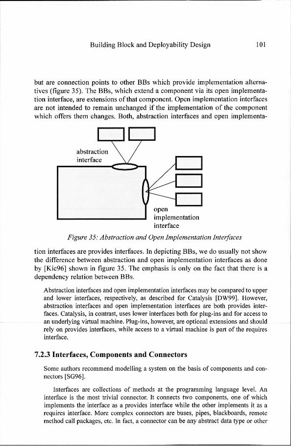
butt are connection points to other BBs which provide implementation alterna-tivess (figure 35). The BBs, which extend a component via its open implementa-tionn interface, are extensions of that component. Open implementation interfaces aree not intended to remain unchanged if the implementation of the component whichh offers them changes. Both, abstraction interfaces and open implementa-
abstraction n interface e
open n implementation n interface e
FigureFigure 35: Abstraction and Open Implementation Interfaces
tionn interfaces are provides interfaces. In depicting BBs, we do usually not show thee difference between abstraction and open implementation interfaces as done byy [Kic96] shown in figure 35. The emphasis is only on the fact that there is a dependencyy relation between BBs.
Abstractionn interfaces and open implementation interfaces may be compared to upper andd lower interfaces, respectively, as described for Catalysis [DW99]. However, abstractionn interfaces and open implementation interfaces are both provides inter-faces.. Catalysis, in contrast, uses lower interfaces both for plug-ins and for access to ann underlying virtual machine. Plug-ins, however, are optional extensions and should relyy on provides interfaces, while access to a virtual machine is part of the requires interface. .
7.2.33 Interfaces, Components and Connectors
Somee authors recommend modelling a system on the basis of components and con-nectorss [SG96].
Interfacess are collections of methods at the programming language level. An interfacee is the most trivial connector. It connects two components, one of which implementss the interface as a provides interface while the other implements it as a requiress interface. More complex connectors are buses, pipes, blackboards, remote methodd call packages, etc. In fact, a connector can be any abstract data type or other

1022 Building Block and Deployability Design
packagee which connects two or more components. In the BBM, all but the most sim-plee connectors are implemented as components themselves.
Thee notion of a connector is useful in top-down modelling. Application entities cann be connected abstractly. The precise properties of a connector can be determined later.. Product variations may require different connectors. The BBM does not use connectorss as a primary concept because the concept of a generic BB can be used instead.. Connectors can be modelled as special classes of generic BB (for an example seee section 7.5.4).
7.2.44 Registration and Call-Back Interfaces
Call-backk interfaces offer a mechanism for making components minimally dependentt on the context in which they execute. Besides the services part of the providess interface, a BB provides a call-back interface through which it can call methodss of the calling BB. Instead of adapting a service-providing BB to many differentt interfaces of using BBs, the service-providing BB sets a standard which hass to be met by using BBs. The service providing BB itself thus remains inde-pendentt of the using BBs while adapting its behaviour.
Thee call-back mechanism is shown in figure 36. BB A defines a service inter-face,, a register interface and a call-back interface. BB B, interested in the service off A, has to register methods, which conform to the call-back interface, with BB A.. A call-back occurs when A calls the registered methods of B.
A A
service e
register r ^ ^
call-back k
D D
methods s
FigureFigure 36: Call Back Mechanism
However,, BB B may have to meet restrictions in the implementation of the call-backk methods.
Exampless are certain interfaces which may not be called during the call-back from A, andd execution time limitations of the call-back (for a broader discussion of these restrictions,, see [Cla85]).
Thee BBM requires that BBs have syntactically only unidirectional relations. Mutuall dependencies are not allowed. This establishes a partial ordering of BBs.

Buildingg Block and Deployability Design 103 3
Thee partial ordering of BBs is a necessary condition for integrating a system incrementally.. If a design requires bidirectional communication, call-back inter-facess have to be used to establish a bidirectional communication. Below, we shalll give guidelines for design with unidirectional relations.
7.2.55 Interfaces, Aspects and Concurrency
Besidess their functional characteristics, interfaces must describe additional infor-mation. .
HeuristicHeuristic 55: Structure interfaces according to aspects.
Theyy enable the connection of aspect functionality which is distributed over BBs.. The interface description of the BB should describe the aspect to which an interfacee belongs.
Similarly,, the restrictions imposed by a concurrency design have to be describedd with an interface, that is, the assumptions about threading have to be madee explicit in the interface description. Examples are information about re-entrancee of interfaces, timing constraints and resource usage.
Besidess the information which is described per interface of a BB, the overall descriptionss of aspect designs and the concurrency design support the under-standingg of the role of the interfaces.
7.33 Component Models
Anotherr facet of BBs is the underlying component model. The component model definess how a component is accessed. In particular, calling conventions for the usee of the interfaces are defined by the component model.
Differentt component models are currently proposed. The most prominent examples aree the Component Object Model (COM) of Microsoft, JavaBeans of Sun and CORBAA of the OMG. Other component models have been developed for specific applications.. To achieve wide applicability, these component models have to demon-stratee their usefulness for different application domains, interoperability with existing (legacy)) software and bridging to other component models. We shall neither explain norr compare these component models. Szyperski [Szy98] gives a good introduction too and comparison of COM, JavaBeanss and CORBA.

104 4 Buildingg Block and Deployability Design
Thee BBM just assumes that a component model is used. Nevertheless, as an example,, we describe the component model of the tss system in appendix A.3.5.1.. The tss component model is a dedicated component model developed in thee mid-eighties to allow flexible design, implementation, loading [Fra97] and testingg of BBs. The tss component model shows that components can be imple-mentedd with littl e overhead. This is an important consideration for embedded systems. .
7.44 Layering
Inn section 4.2.1 layering of objects was introduced for separating functionality withh different evolution characteristics. Layering for BBs extends and refines the notionn of layering of objects. BBs make use of interface abstractions of other BBs.. The abstraction serves as an infrastructure for the using BBs. Each BB pro-videss a part of an infrastructure for one or more using BBs. The BBM requires thee infrastructure to be independent of the supported BBs. To achieve this inde-pendence,, mutual relations are transformed in unidirectional relations (see also sectionn 7.4.2).
Thee BBM uses a layer as a clustering of functionality which has unidirec-tionall syntactical relations only, that is, a layer depends on lower layers, and higherr layers may depend on it. Parnas identifies layering, besides information hiding,, as a desirable property of a system structure [Par72].
HeuristicHeuristic 56: Use layering for BBs on two levels. Subsystems, which are collectionscollections of BBs, are layered. These layers are based on thethe classification of layers of domain objects done during objectobject design.
HeuristicHeuristic 57: Individual BBs within subsystems are also layered in rela-tiontion to other BBs.
Layeringg of subsystems wil l be discussed in this section. Section 7.5 on generic andd specific functionality describes layering of individual BBs.
7.4.11 Layering Principles
Structuringg of functionality in an infrastructure and its using applications can be basedd on several principles: layers can have a different scope of visibility, layers cann be used conceptually or even in implementation, and layers can provide dif-

Buildingg Block and Deploy ability Design 105 5
ferentt degrees of completeness. The following subsections introduce the differ-entt kinds of layering.
Applicationn versus Technology Layering
HeuristicHeuristic 58: A common principle for the layering of software is to sepa-raterate hardware-technology-oriented functionality from application-orientedapplication-oriented functionality.
Hardware-technology-orientedd functionality is seen as the base on which the applica-tion-orientedd functionality is implemented (section 4.2.1). This approach is often takenn in interactive systems. If the user interaction needs to be regularly adapted or extended,, this layering approach (figure 37) provides flexibility since changing the applicationn on the basis of a stable infrastructure restricts the impact of those changes.. A variant of this principle is the separation of base technology from applica-
Userr Interaction
HWW Technology Oriented Services
FigureFigure 37: User vs. HW Technology Layering
tionn functionality. [BGK*99] and [RE99] use several layers to bridge from base tech-nologyy to application-specific frameworks.
Abstractionn from HW
AA related layering principle is one in which layers abstract from the concrete HW [Dij68].. Each layer provides abstractions for the higher layers. Layers are also called virtuall machines. In figure 38 the lowest layer consists of the HW drivers. Logical driverss abstract HW specific attributes and constitute the second layer. Common

106 6 Buildingg Block and Deployability Design
servicess are a collection of services used by many applications. The user applications, finally,, constitute the highest layer.
Userr Application
Commonn Services
Logicall Drivers
HWW Drivers
FigureFigure 38: Abstraction from HW
HeuristicHeuristic 59: Construct layers as virtual machines for higher layers.
Genericc versus Specific Functionality
HeuristicHeuristic 60: Another way of introducing layers is to distinguish between genericgeneric and specific functionality.
Genericc functionality is the infrastructure on which specific functionality is built (fig-uree 39). This principle is used when generic middleware is separated from applica-
Speciflcc Functionality
Genericc Functionality
FigureFigure 39: Generic vs. Specific
tionn programs. More generally, interface abstractions can be encapsulated in a BB. Thee BB which actually provides the functionality of the interface BB and the BB whichh uses these interface abstractions to access the functionality are both located in aa higher layer. The BB which contains the interface abstractions is more generic than thee other ones and therefore resides in a lower layer.
Example:: tss Layering Principles
Withinn the tss system two principles for layering have been combined, notably abstractionn from hardware and generic vs. specific functionality.
Thee rule that all relations are uni-directional creates some tension between the applicationn of both principles. Generic services are often hardware-independent.

Buildingg Block and Deployability Design 107 7
Accordingg to the abstraction from hardware principle, these services are located in higherr layers, whereas according to the generic vs. specific functionality, these serv-icess are located in lower layers. For example, an interface between hardware drivers andd the remainder of the system is more generic than the specific cases of the hard-waree drivers. Therefore, the BB containing the interface has to be lower than the spe-cificc hardware drivers. However, drivers are closer to thee hardware itself. No general rulee exists to reconcile these two principles for the actual layering of system function-ality.. A decision has to be taken for each function separately.
Thee tss central controller layers (subsystems) (see section 7.4.4) are based on the abstractionn from hardware principle. But the system infrastructure generics (see below)) are also placed in the lowest layer. Within each layer there is a micro-layering whichh separates generic from specific functionality (see section 7.5.3).
7.4.22 Incremental Layering
AA layer is said to be incremental if the dependency relation of this layer satisfies thee following criteria:
1.. The import graph is acyclic, that is, the dependencies are unidirectional.
2.. The semantics of layer L may depend only on the semantics of layers from whichh L imports.
Thee second criterion especially states that a BB must have well-defined meaning evenn if call-back methods have not (yet) been registered. This means the BB may neitherr depend on the presence of registered call-back methods nor on the semanticss of these methods.
Ann incremental layer builds a platform for BBs of the higher layers, that is, it implementss a virtual machine. The semantic independence of higher layers requiress functional completeness of an incremental layer and the layers below it. Wee call this functional completeness of a layered subsystem its platform prop-erty. erty.
Layeringg is already started during object design. The classification of functionality in layerss is a step for getting meaningful functionality per layer from the application domain. .
Thiss platform property requires careful design. Techniques for defining a fine-grainedd platform for a single BB wil l be described in section 7.5.
Thee main reason for incremental layering is complexity management. A system with incrementall layers can be integrated and tested layer by layer. [Dij68] and [HFC76] mentionedd incremental testability as one of the key advantages of incremental layers.
108 8 Buildingg Block and Deployability Design
Thiss partial (in)dependence of layers is a compromise between total independence, whichh is not possible, and total dependence, which is not desirable.
AA system is integrated according to its incremental layer structure. They are compiledd and linked incrementally. If the target system is equipped with an incrementall loader, the layers can be loaded incrementally. Each increment may bee developed and tested as soon as enough information on the underlying system iss available. System construction does not have to wait until all the increments aree present. A small (core) system may be built from initial BBs. The system mayy be extended repeatedly with new increments until the entire system is ready. Incrementall layering is a key concept of the BBM.
7.4.33 Mor e Facets of Layering
Besidess the layering principles and the incremental nature of layers, other facets off layering are important. The following subsections discuss several alternative strategiess for layering.
7.4.3.11 Conceptual versus Strict Layering
Conceptuall layering is a design technique which models functionality in such a wayy that a particular layer is conceptually independent of other layers.
Strictt layering is an implementation technique in which no compile or link timee dependencies exist from a layer to a higher layer. This technique makes it possiblee to build each layer (or rather each increment) independently of the higherr layers. Furthermore, a system can be loaded increment by increment.
Strictt layering implies conceptual layering, but the reverse does not hold.
Ann example of conceptual layering only is a middleware layer which is independent off its using applications but has hardwired knowledge of these applications to be able too activate them. In the implementation such a middleware layer needs to be updated forr new applications.
Thee BBM relies on strict layering of BBs. Strict layering is a precondition both forr incrementally adding new BBs to the deployed system and for removing BBs fromm it.
7.4.3.22 Opaque versus Transparent Layering
Theree are two alternatives to the visibility of layers:
Buildingg Block and Deployability Design 109 9
opaquee layering: each layer hides the layers below it. A layer may only use functionalityy provided by the layer directly below it.
transparentt layering: layers do not hide the lower layers. A layer may use all lower-levell layers.
Otherr terms for opaque and transparent layering are strict layering (different fromm our usage of the term) and non-strict layering, respectively, proposed by [Szy98],, or closed and open architecture, respectively, proposed by [RBP*91],
Opaquee layering requires each layer either to provide an additional abstrac-tionn for all the lower-layer services needed in higher layers or to add dummy interfaces.. This eases the development of a particular layer, because a layer uses onlyy interfaces of one layer below. Furthermore, restructuring of BBs in a lower layerr is shielded from visibility of a higher layer by an opaque layer. On the other hand,, updating functionality becomes more complex. Functionality from the lowerr layers used by a higher layer has to be presented to the higher layer in one formm or another. Updates and successive testing are therefore required even if no functionalityy within a layer itself has been changed.
Transparentt layering assumes that each layer provides only its own services. Onlyy if an additional abstraction or an additional service is needed, an interface iss introduced in a layer. In the case of transparent layering the implementors of a layerr must know in which layer they wil l find the necessary interfaces. No main-tenancee effort is necessary in intermediate layers for making new or changed servicess of the lower layers available.
Opaquee layering focuses on the using layer. The usage relations are defined to bee exactly those of one layer with the layer immediately below it. Transparent layeringg focuses on the providing layer. The changes necessary after an update aree restricted to the providing layer where a service is located and the layers of itss direct users. The users may be from multiple higher layers. No effort in inter-mediatee layers is necessary.
Thee BBM permits both techniques.
HeuristicHeuristic 61: The usage of transparent layers is favourable to the usage ofof opaque ones.
HeuristicHeuristic 62: Opacity is used for layers that function as facades, such as abstractionabstraction layers for hardware, operating system or mid-dleware. dleware.
Thee facade pattern is described in ([GHJ*94])

110 0 Buildingg Block and Deployability Design
7.4.3.33 Partial versus Complete Layering
Sometimess systems are designed with partial layering only. For example, func-tionalityy that belongs to an application domain may be layered while functional-ityy that provides computing resources is outside this layering. An example is givenn in figure 40.
Userr Application
Commonn Services
Logicall Drivers
HWW Drivers
FigureFigure 40: Partial Layering
Al ll layers may make use of the computing resources and the computing resourcess may or may not access any of the layered functionality. The computing resourcess are a kind of general entity which must always be present and needs to bee adapted to entities present in the layers.
Thee BBM does not allow partial layering. Instead, if, in the example, partial layeringg were to be restricted so that only layered functionality would access the computingg resources and, if necessary, register call-backs, it would be equivalent too a complete layering in which the computing resources are the lowest layer and aree visible to all the other layers. In the last situation there would be no bidirec-tionall dependencies.
7.4.3.44 Communication and Layers
HeuristicHeuristic 63: Use layers to structure communication in a system.
Supposee a functional element in the system communicates with another one in thee same layer. Communication happens, then, between elements of the same conceptuall level. However, if the functional element may only have relations to functionall elements of lower layers, the communication may not be implemented directly.. Unidirectional dependencies require that such a communication relation bee established indirectly. The lower layers are used for the implementation of the
Computing g Resources s

Buildingg Block and Deployability Design 111 1
peer-to-peerr communication (figure 41). They transport messages from one peer too the other and notify the receiving peer.
nH H i i
k k -J— —
FigureFigure 41: Indirect Peer-to-F'eer Communication
Thiss model of peer-to-peer communication introduces semantic relations but noo direct syntactic relations between the communicating parties. The ISO-OSI communicationn model [DZ83] made this communication structuring popular for computer-to-computerr communication. Layered subsystems in a distributed sys-temm usually also communicate in this way. In BBM-based systems peer-to-peer communicationn will always be implemented via indirect communication.
Forr reasons of performance, an optimised version of layered peer-to-peer communi-cationn based on transparent layering may be introduced. Layered application entities makee direct use of a lower-layer communication facility without intermediate pack-aging.. Available knowledge about the sending environment, the communication channell and the receiving environment is used to minimise intermediate processing. Requiredd functionality of intermediate layers may be implemented by the application layerss taking advantage of the application knowledge. The communication within the tsss system is based on such optimised peer-to-peer communication (section A.2.3).
7.4.44 Example: tss Subsystems
tsss layered subsystems have been described in section 4.3. They comprise the extendedd operating system, equipment maintenance, logical resource management andd service management. The subsystems have incremental semantics. The layering iss strict, transparent and complete. The operating system provides a facade interface (opaquee layering, heuristic 62).

112 2 Buildingg Block and Deployability Design
7.55 Generic and Specific Functionality
AA very important way of structuring software is by separating generic from spe-cificc functionality. Functionality of similar applications is analysed for diversity. Thiss analysis is applied to domain objects, domain functions, algorithms, etc. [CHW98].. The common part is factored out and captured as an abstract concept. Thee common part is called generic, the diverse parts are called specific.
Separationn of functionality into generic functionality and specific functionality is also presentt in object-oriented modelling and in design patterns [GHJ*94] (see table 3).
Patterns s
OOO modelling
strategyy pattern
container r
templatee method pattern
bridgee pattern
observerr pattern
Generic c
supertype e
dataa structure
algorithm m
skeletonn algorithm
interface e
eventt source
Specifics s
subtypes s
algorithms s
dataa structures
fill-infill-in steps
implementations s
eventt listeners
TableTable 3: Examples of Separation of Generic and Specifics
Thee observer pattern which decouples event source from event listeners is an extreme formm of generic and specific. The coupling between the generic part and potentially manyy specific listeners is reduced to events. Essentially, two independent entities are coupledd via some events. Common to all examples is that there may be several spe-cificss that are related to one generic.
Thee specific part is an extension of the generic part. Replacing functionality of thee generic part by the specific is not intended. Functional units are built by com-biningg a generic part and a specific part. Achieving stable generic parts for an applicationn domain eases evolution.
Thee separation of generic and specific functionality is relevant for areas other than softwaree too. Examples are system requirements, domain modelling, hardware, and developmentt and customer documentation. Using the same separation in related areass makes correlating them easier. Domain terminology, for instance, may be extendedd with those generic concepts.
Buildingg Block and Deployability Design 113 3
Notee that there may be degrees of genericity. Certain pieces of functions are com-monn to all members of the family, whereas others are common to only a few mem-berss of the family. In the latter case we still have generic functionality, but on a smallerr scale.
Thee embodiment of the generic functionality represents a major part of the know-howw of an application domain, cf. the domain kernel of Gomaa [Gom95].
HeuristicHeuristic 64: Separate common functionality from specific functionality.
Analysiss of functionality in terms of generic and specific functionality is the key conceptt in architecting a product family [Par76]. Frequently used terms are com-monalitymonality analysis [CHW98] and diversity analysis. It is common experience that diversityy analysis is more effective for identifying generic parts than commonal-ityy analysis [KMM96] ,
HeuristicHeuristic 65: Look for the diverse parts in similar functionality for differ-entfeatures. entfeatures.
7.5.11 Generic and Specific BBs
Genericc and specific functionality is captured in different BBs. A generic BB containss generic functionality and a specific BB contains specific functionality. AA specific BB extends the functionality of a generic BB. A generic BB is a com-ponentt framework [Szy98] to which specific BBs, also called plug-ins, are added too extend its functionality. Figure 42 shows the basic inter-BB pattern generated byy the BBM.
AA generic BB defines standards for its specific BBs similar to a superclass settingg standards for its subclasses. However, the specific BB extends the generic BBB conservatively, whereas subclasses are often also allowed to overwrite parts off the superclass.
[FS97]] call those frameworks black-box frameworks in contrast to object-oriented frameworks,, which are called white-box frameworks.
Moree specifically, the generic BB defines interfaces for its specific BBs. If the interfacee between the generic BB and the specific BB is based on a domain object,, the interface is stable because of its anchoring in the application domain. Usually,, however, the interfaces between generic and specific BB depend on the implementationn of the generic BB.
Implementation-dependentt interfaces are called open implementation interfaces [Kic96]] (see section 7.2.2). Call-back methods, also called hook methods in [FS97],

114 4 Buildingg Block and Deployability Design
Specificc BB Specificc BB Specificc BB
abstraction n interface e
Genericc BB FigureFigure 42: Generic BB and Specific BBs
decouplee the generic behaviour of an application domain, encoded by the generic BB, fromm the specific instantiations needed for a particular application, as encoded by the specificc BB.
Generall application processing steps are executed by the generic BB. The invo-cationn of methods of specific BBs customises and extends this generic behaviour too one for the specific application domain. Inversion of control [FS97] means thatt the generic BB (rather than each specific BB) has control and gives it to spe-cificc BBs to do certain actions.
HeuristicHeuristic 66: Use inversion of control for designing the functionality of a genericgeneric BBs.
Forr instance, external event handling is effected in the generic BB, which decides whichh methods of a specific BB to call in response to those events.
Modellingg a generic service requires careful analysis. To become stable, a genericc BB usually undergoes several redesigns [Sch97].
HeuristicHeuristic 67: A generic BB is stable if new specific functionalities may be basedbased on the generic BB without changing it.
Off course, generic BBs may be adapted and/or added during the lifetime of the productt family. A generic BB embodies the similarities of certain functions. Therefore,, changes in a good generic BB are rarely necessary. However, changes

Buildingg Block and Deployability Design 115 5
inn a generic BB almost always have consequences for all the corresponding spe-cificc BBs.
Eachh specific BB uses the functionality provided by thee generic in its own way. Con-traryy to superclasses, a BB hides its internal structure. The specific BBs do not have directt access to the internal details of the generics. This means that the specific BBs mayy use only the interfaces provided by the generic to access the generic functional-ity. .
7.5.22 Generic and Specific BB Roles
Inn practical situations a BB wil l often be both, generic and specific. It is there-foree necessary to use the term generic and specific in relation to some functional-ity.. The terms generic role and specific role of a BB are used to denote that a BB containss generic or specific functionality. A BB can have several generic and / or specificc roles.
Mostt BBs have multiple specific roles. This is similar to a class structure with multi-plee inheritance in object-oriented modelling. The difference with multiple inheritance iss that generic BBs have explicit interfaces and the generic-specific relation is not recursive. .
Notee that we use the term generic BB without reference to its particular role if it iss clear from the context what that role is. Thus, a BB which has at least one genericc role may be called a genericc BB for short.
7.5.33 Generics and Layering
Thee BBM uses layering to structure overall functionality (section 7.4). But layer-ingg is also used to structure inter-BB relations. Since a specific BB is an exten-sionn of a generic one, the specific BB is dependent on the generic BB. The specificc BB imports an interface of the generic BB.
Besidess syntactical independence of its specific BBs, a genericc BB is required too be semantically independent too. Layers have an incremental character (sec-tionn 7.4.2), but so does a generic BB with respect to its specifics. Semantic inde-pendencee means that a generic BB without registered call-backs to specific functionss has to perform basic functions without leading to any error (section 11.7)) to enable incremental testing.
AA generic BB is a kind of infrastructure on top of which specific BBs are located.. The generic BB is located in a layer below the specific BBs.

1166 Building Block and Deployability Design
Thiss may seem counter-intuitive from the point of view of object-oriented modelling inn which super classes are usually drawn above subclasses. In contrast, the BBM uses thee notion of an extensible platform upon which further BBs are constructed (see fig-uree 43).
Specificc SI Specificc S2 Specificc S3
>r >r requires s
use e J J
Generic c
FigureFigure 43: Generic and Specifics with Interfaces
Forr instance an operating system can to a great extent be modelled to consist of genericc services which are used by almost all the application.
Specificc BBs register call-backs with their generic BBs (section 7.2.4). In fact, BBss with generic roles are the only BBs that provide a registration interface. The BBss with specific roles are the only BBs that use the registration interface and havee a call-back interface. In figure 43 a generic BB is depicted with its specif-ics,, together with the registration and use interfaces of the generic. The arrows indicatee method invocations.
7.5.44 Classification of Generic BBs
Genericc BBs can be classified according to patterns. The idea is that the very generall concept of separation between generic and specific functionality leads to aa number of domain-specific types of generics. We describe four different types ass part of the core BBM. The list is not exhaustive but can be extended with new oness by specialised versions of the BBM.
Buildingg Block and Deployability Design 117 7
Abstractionn Generic
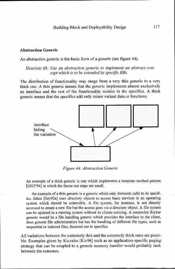
Ann abstraction generic is the basic form of a generic (see figure 44).
HeuristicHeuristic 68: Use an abstraction generic to implement an abstract con-ceptcept which is to be extended by specific BBs.
Thee distribution of functionality may range from a very thin generic to a very thickk one. A thin generic means that the generic implements almost exclusively ann interface and the rest of the functionality resides in the specifics. A thick genericc means that the specifics add only minor variant data or functions.
interface e hiding g thee variation
FigureFigure 44: Abstraction Generic
Ann example of a thick generic is one which implements a template method pattern [GHJ*94]] in which the factor-out steps are small.
Ann example of a thin generic is a generic which only forwards calls to its specif-ics.. Ethos [Szy92a] uses directory objects to access basic services in an operating systemm which should be extensible. A file system, for instance, is not directly accessedd to create a new file but the access goes via a directory object. A file system cann be updated in a running system without its clients noticing. A somewhat thicker genericc would be a file handling generic which provides the interface to the client, doess general file administration but has the handling of different file types, such as sequentiall or indexed files, factored out in specifics.
Al ll variations between the extremely thin and the extremely thick ones are possi-ble.. Examples given by Kiczales [Kic96] such as an application-specific paging strategyy that can be coupled to a generic memory handler would probably rank betweenn the extremes.
1188 Building Block and Deployability Design
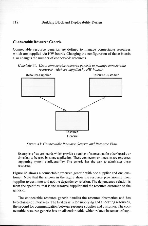
Connectablee Resource Generic
Connectablee resource generics are defined to manage connectable resources whichh are supplied via HW boards. Changing the configuration of those boards alsoo changes the number of connectable resources.
HeuristicHeuristic 69: Use a connectable resource generic to manage connectable resourcesresources which are supplied by HW boards.
Resourcee Supplier Resource Customer
Resource e Generic c
FigureFigure 45: Connectable Resource Generic and Resource Flow
Exampless of tss are boards which provide a number of connectors for other boards, or timeslotss to be used by some application. These connectors or timeslots are resources supportingg system configurability. The generic has the task to administer these resources. .
Figuree 45 shows a connectable resource generic with one supplier and one cus-tomer.. Note that the arrows in the figure show the resource provisioning from supplierr to customer and not thee dependency relation. The dependency relation is fromm the specifics, that is the resource supplier and the resource customer, to the generic. .
Thee connectable resource generic handles the resource abstraction and has twoo classes of interfaces. The first class is for supplying and allocating resources, thee second for communication between resource supplier and customer. The con-nectablee resource generic has an allocation table which relates instances of sup-
Buildingg Block and Deployability Design 119 9
plierss to instances of customers. The communication interfaces have one of the followingg characteristics:
aa customer instance signals some event to its supplier instance,
aa supplier instance notifies all the related customer instances (broadcast) aboutt some event, and
aa supplier instance notifies a specific customer instance about some event on thee basis of some selection criteria.
Supplierss and customers of a connectable resource generic may evolve inde-pendently.. A connectable resource generic bears some resemblance to a bottle-neckk interface [Szy98]. A bottleneck interface couples two independently extensiblee abstractions and is itself not extensible. A connectable resource genericc also allows independent extension of suppliers and customers via their respectivee specific BBs.
Systemm Infrastructur e Generic
Systemm infrastructure generics provide an operating infrastructure for application BBs.. System infrastructure denotes a collection of services which is part of the operatingg system, standard UI functionality, or generic and domain-specific mid-dleware. .
HeuristicHeuristic 70: Design a system infrastructure generic for functionality whichwhich provides an operating infrastructure for almost all applicationapplication BBs.
Systemm infrastructure generics (SIG) are a means for encapsulating these serv-ices.. The characteristic of a SIG is that all application BBs are potential specifics off it. The operating infrastructure provides the basic framework whereas individ-uall BBs only provide increments.
SIGss may administer system resources such as processor time and memory pools, andd standardise system functionality such as the user interface, a recovery strategy or errorr handling.
HeuristicHeuristic 71: System Infrastructure Generics must provide interfaces for applicationapplication BBs for indicating their resource requirements.
Thee SIG wil l either have service interfaces to provide data directly or registration interfacess to register call-backs which the SIG uses to retrieve the data from the applicationn BBs.

1200 Building Block and Deployability Design
Genericc parts of aspects (chapter 5) which can share a common implementa-tionn are factored out into SIGs. This leads to an instantiatable aspect infrastruc-ture. .
AA SIG for recovery handling is such an example. A generic report handler may be usedd by the configuration management aspect and the fault management aspect. An internall message handler may be used by more aspects.
Sincee these generics offer very generic functionality, they are located low in the systemm hierarchy of layers, i.e. they can be seen as part of an extended operating system.. Layering them low in the system is an example of the generic-versus-specificspecific functionality layering principle. An application BB has a specific role forr many of the SIGs. Figure 46 shows a BB together with three SIGs.
Buildingg Block
SIG G
FigureFigure 46: System Infrastructure Generics
Standardisationn of SIGs may go so far that specific functionality is reduced to spe-cificc data instances. Al l the relevant algorithms reside in the SIG and the specific data instancess reside in the specific parts. In such a case BBs do not access these data directly,, but through a SIG.
Ann example of such a SIG is one which handles exceptions. The SIG defines standardisedd functionality such as the handling of severity of exceptions, writing to a logg file and communication to a user interface, whereas the actual severity, output formatss and reporting texts are located in the application BB.

Buildingg Block and Deployability Design 121 1
Usingg a SIG to implement system functions such as exception handling is an alternativee to a coded case statement with each case alternative representing a spe-cificc instance of an exception. Maintaining lists of case alternatives for an evolving systemm leads to frequent changes in the source code of the exception handler. This is aa potential source of errors. In contrast to this a SIG is not changed. The list of differ-entt exceptions in a specific product is automatically built by the configuration of selectedd BBs in the product. Consider the addition of a BB to the system. No recom-pilation,, relinking or reloading of, for instance, exception handling is necessary. Instead,, the BBs define their own exceptions and make them known to exception handling.. After adding the Building Block, the system will have an adapted list of exceptions.. There are, hence, no separate configuration files or common include files inn the system.
Thee use of the SIG can reduces the code of the specific BBs considerably. Fur-thermore,, this standardisation allows automatic code generation. Specific functional-ityy of a SIG may be reduced to parametrised data structures. The collection of specificc BBs together with the SIG implement a configurable table in the running systemm whereby all access methods are implemented in the SIG itself. The parts that extendd the table can be generated automatically.
Thee tss system used a specific database-based tool (section 11.8) for data genera-tion.. Because of their relevance for the whole system, data can easily be reviewed andd changed without entering an implementation phase. Part of the production of a BBB is the code generation for all tool-supported SIGs. An implementor of a BB may nott even be aware that some of the SIG-specific data of his BB form part of the Buildingg Block.
Oftenn when diagrams with relations between BBs are drawn, the relations to SIGss are not shown because all the BBs are specifics of at least some of the SIGs. .
Layerr Access Generic
Layerr access generics provide access to a layer's functionality. They restrict the visibilit yy of the structure within a layer for higher layers, i.e. references are chan-nelledd through a number of specifically designed indirections. The advantages of layerr access generics are, first, that higher-layer BBs only have to know about layerr access generics of the lower layers, and, second, that they provide for con-figurabilityfigurability of BBs in lower layers without any need to update BBs in higher lay-ers. .
HeuristicHeuristic 72: Design a layer access generic to restrict the visibility of the structurestructure of a layer for higher layers.

122 2 Buildingg Block and Deployability Design
AA specific pattern is used to achieve this purpose. In contrast to normal inter-faces,, which are often conceived as being on top of a BB, layer access generics aree located below the BBs they provide access to. The BB register themselves withh the layer access generic (see section 7.2.4). Figure 47 shows import rela-
BB B BB B
cBB B
Generic c
Layer r Access s Generic c
FigureFigure 47: Layer Access Generic
tionss of BBs in a lower and a higher layer. Configurable BBs (cBB) of lower lay-erss have no provides interface. They can be replaced without affecting higher layers.. Also, changes within the lower layer are less likely to propagate to higher layers.. Layer access generics are brokers for layer functionality.
Example:: tss Generics
Thee tss system has around 50 generics. We shall mention some of them below with-outt going into much detail.
Exampless of Abstraction Generics from the OS subsystem include file handling andd I/O device handling. File handling includes the operations open, close, write and read.. Specifics of file handling have specialised handlers for different file types such ass sequential or indexed files. I/O device handling includes the operations mount, dis-mount,, assign and deassign. I/O device handling has separate specifics for handling differentt device types such as PCs, printers and disks.
Exampless of abstraction generics from the equipment management subsystem includee two for handling two classes of peripheral cards. Peripheral card handling recoverss and supervises peripheral cards in the central controller. The protocols and dataa structures are standardised for all cards and they belong to the generic part. Spe-
Buildingg Block and Deployability Design 123 3
cificc parts are reduced to peripheral card-specific data structures and parameters. For eachh peripheral card type, there is a separate specific part.
Exampless of abstraction generics from the logical resource management subsys-temm include generics for administering generic classes of analog and digital sub-scriberr lines and trunk lines. Digit analysis and automatic audible responses are other abstractionn generics. Digit analysis has as its input digit strings and has specifics for differentt destination types such as analog or digital subscribers or PABXs. Audible responsee generic has specifics for single and periodic announcements.
Exampless of abstraction generics in the service management subsystem include thee call-handling generic which implements basic call handling such as call set-up, calll phase and call release, which are valid for (almost) all call types. It can be extendedd to different signalling handlers. Another generic handles the generic call forwardingg feature. Specifics are for call forwarding on absent, on busy or on other conditions. .
Thee equipment management subsystem contains four connectable resource gener-icss for administering hardware (-related) resources. Two generics administer internal buss slots, the so-called time slot (TS) generic and the so-called universal peripheral slott (UPS) generic. External connections are administered by the so-called circuit generic,, which is based on a 64kbit communication channel abstraction. A fourth connectablee resource generic establishes pools of dynamically allocatable communi-cationn channels for a group of subscribers, so-called concentration groups. Figure 48 showss how Equipment Maintenance structuring is based on mirroring of the periph-erall hardware structure to a central controller BB structure.
Threee generics of equipment management also have the role of a layer access generic.. The circuit generic, the TS generic and the concentration group generic func-tionn as a layer interface to the higher layers LRM and SM.
Thee OS contains a number of SIGs. They are persistent data handling, process handling,, memory management, user interface presentation data handling, recovery handlingg and exception handling.
7.66 Interfaces Revisited
Afterr the sections on layers (section 7.4) and generic BBs (section 7.5), we shall takee another look at interfaces. In section 7.2 we made a distinction between pro-videss and requires interfaces. From the discussion of incremental layering it is clearr that a BB may depend only on BBs in lower layers. As a consequence a

124 4 Buildingg Block and Deployability Design
peripherall HW
PUa a
UPS S
PUa a PUb b
PGC C
PUb b PUC C
FigureFigure 48: System Structure with HW Mirroring in EM
requiress interface relates to BBs in lower layers only and a provides interface relatess to higher layers only.
Theree are, however, two types of interfaces, call-back interfaces and so-called first-accesss interfaces (see section A.3.3.4), of which it is not so clear whether theyy are provides or requires interfaces. One may say that a BB requires certain processingg to be done by a calling BB which knows the precise content of a data structuree or that a BB provides a first-access interface to be used by the recovery manager.. Note that in both cases the activation goes from the lower BB to the higherr BB. In the first case, a using BB has registered call-back methods, whereass in the second case a standardised entry in a BB header allows the recov-eryy manager to activate initialisation methods.

Buildingg Block and Deployability Design 125 5
provides s interface e
requires s interface e
service e interface e + +
call-back k interface e
providess standard interfacee + first-access off other BBs interface
FigureFigure 49: BBM Interfaces
However,, contrary to the use of require and provide suggested above, call-backk interfaces are part of the provides interface and the first-access interface is partt of the requires interface, because the incrementality of a BBM-based system iss the leading concern for the definition of provides and requires interfaces. Even iff a BB has only limited processing capabilities in a certain situation, the BB may nott depend on the presence of a call-back method. A BB always has to imple-mentt some default behaviour if no call-back method is present. Call-back inter-facess are in a sense optional.
AA similar argument as for call-back methods applies to the first-access meth-ods.. A BB requires the recovery manager to call the BB's initialisation methods too be initialised. Therefore, first-access methods are part of the requires interface off the BB. Figure 49 shows the provides interface at the top and the requires interfacee at the bottom of a BB to indicate how interfaces support incrementality.
7.77 Grouping of BBs
Hierarchicall components are components which consist of components them-selves.. This is a useful means for abstraction. The BBM does not support hierar-chicall BBs. A BB is a black box, that is, its internal design is not visible, and it is deployedd as one unit. Recursive deployment does not seem to be a useful con-cept. .

126 6 Buildingg Block and Deployability Design
However,, collections of BBs can be grouped to a white box component, that is,, a component that does not hide its internals. Examples of such groupings are layerss (section 7.4), a feature set (see section 8.3), that is, a set of BBs which implementss a certain feature, or managed object related BBs (controlling and controlledd BB) (see section 10.2.1). The BBs of a feature set may belong to dif-ferentt subsystems.
HeuristicHeuristic 73: Apart from a BB itself, the collection of BBs of a white box componentcomponent can be packaged as unit of deployment.
Packagingg of BBs into larger deployment sets is described in section 7.9. In a runningg system only deployment units are recognisable.
Substitutabilit y y
Twoo BBs are substitutable if they have the same provides and requires interfaces andd if they are fulfillin g the same role in the architecture.
However,, there may be cases where technical substitutability as defined abovee is not enough. If both BBs were planned and one of them is not just an improvementt of the other, difference in features is involved (see section 8.3.4). Dependingg on the feature set of the product, one of them will be chosen.
HeuristicHeuristic 74: If two substitutable BBs are to be present in the same prod-uct,uct, the BBM requires that there must also be some generic whichwhich switches between the two.
7.88 Architectura l Skeleton
Ann architectural skeleton is the result of structuring the software in incremental layerss which themselves consist of generic and specific BBs. An architectural skeletonskeleton is defined as the collection of generic BBs in the different layers. The specificc BBs that implement the wanted functionality constitute the "meat". The skeleton,, however, provides a structured platform at different levels, which sup-portss the rapid creation of products. It is an incrementally layered component framework.framework. The skeleton implements the stable structure in a domain. It is a genericc domain architecture. Abstracting from internal structure, an architectural skeletonn is also called a product platform [ML97].

Buildingg Block and Deployability Design 127
FigureFigure 50: Architectural Skeleton
Figuree 50 gives an example of an architectural skeleton together with the sets off specific BBs. The architectural skeleton consists of the shaded BBs only. They aree represented in two types of generic BBs. First, there are generics in each of thee three layers of the system. Secondly, there are two SIGs in the lowest layer (transparentt layering). Note that the relations of the system infrastructure generic withh their specifics are not indicated, because potentially all the Building Blocks aree specifics of a system infrastructure generic.
Anotherr important point in this example is that the interfaces of the subsys-temss (or layers) are represented by generics only. These so-called layer access genericss are brokers of the layer functionality towards higher layers. They allow configurabilityy within a layer without affecting the higher layers.
Notee that the system is incremental in two ways. First, the system can be built subsystemm by subsystem. Secondly, BBs can be added in each subsystem.
HeuristicHeuristic 75: Choose generic BBs in such a way that stability of architec-turaltural skeleton increases.

128 8 Buildingg Block and Deployability Design
Anotherr important point is that BBM-based systems are always open. A new BB mayy always be added to generics using them as its relative infrastructure. Such a neww BB has a specific role but may also have generic roles. Thus, a completed systemm can always be extended if it provides interfaces to access its functional-ity.. This can be realised either by removing a BB which has no provides interface andd substituting it by one that has a provides interface, or by using the provides interfacee of a BB and adding new functionality.
AA self-describing component is a component that may be introduced into a systemm without requiring adaptations in other parts in the system.
HeuristicHeuristic 76: Make a BB is a self-describing component by letting it com-municatemunicate its characteristics such as its resource require-mentsments to the infrastructure.
Inn particular, the infrastructure should not be adapted because of requirements imposedd by a component. In this way the exchange or adaptation of a component doess not have any direct consequences for the rest of the system. Aspect com-pletenesss (section 5.6.1) is a way to make BBs self-describing.
AA system integration approach has a low integration complexity if it can be basedd on lists of components without requiring adaptations in these components forr the sake of integration. In particular, if the infrastructure provides all facili-tiess to make components self-describing, the complexity of resource manage-mentt decreases considerably because it is separated into a requesting and an administeringg part. In particular, the requirements of resources are part of the componentss themselves. The BBM uses such an integration approach (see sec-tionn 11.7).
7.99 Deployability Design
Deployabilityy design is about possible deployment scenarios of the products. Addresss spaces (section 6.1) are also used within deployability design.
Thee input for deployment scenarios may come from the customer, from prod-uctt management or from technology assessment requiring a certain HW parti-tioning.. Geographic distribution, if required, will often come directly from the customer. .

Buildingg Block and Deployability Design 129 9
BBss are the minimal units of deployment. However, for commercial or other reasons,, BBs may be packaged to larger sets. Delivery will be in statically or dynamicallyy linked code libraries. Since the library structure is important for the flexibilit yy of software upgrading care should be taken when BBs are packaged.
Ass described earlier, address spaces are boundaries for objects, BBs and threadss (see section 6.1). Address spaces may also be used for fault containment andd recovery (see below). Furthermore, the flexibilit y to move BBs across HW instancess is based on the presence of BBs implementing all requires interfaces of thee moved BBs at the target location.
Deployabilityy design consists of the following steps:
Determiningg fault containment units
Faultt containment units are chosen to confine the consequences of failures and to bee able to do a recovery from the failure. Fault containment units should not crosss HW boundaries. Design has to take care that a fault containment unit can alwayss synchronise with the rest of the system.
HeuristicHeuristic 77: Select a set of objects in such a way that the set may be independentlyindependently recoverable when an error occurs.
Thiss may require refactoring in object design.
Determiningg possible deployment scenarios
Deploymentt scenarios have to take the following factors into account:
differentt geographic locations,
HWW partitioning and
differentt SW address spaces.
HeuristicHeuristic 78: Align BB-, thread-, fault containment unit- boundaries to HWHW instances
Thiss may lead to refactoring in the respective design task.

130 0 Buildingg Block and Deployability Design
Packagingg BBs to deployment sets
BBss are deployment units. They may be packaged for commercial or practical deploymentt reasons into deployment sets. Product management may package BB,, taking into account:
sellablee units (basic product may be one unit), that is, a commercial compo-nentt may be different from a technical component (visibility to the customer), and d
independentt evolvability.
HeuristicHeuristic 79: Package BBs to deployment sets such that independent sell-inging and evolution remains possible.
Deploymentt sets consist of executables and libraries.
White-boxx collections of BBs such as subsystems or feature sets (see section 7.7) aree examples of useful deployment sets.
Generatingg data files
Dataa files are used amongst others for initial or default configuration values, per-sistentt data, international strings, font libraries, sounds, tones and announce-ments. .
Thee creation of a tss product is described in section A.4.
Heuristicss Summary of BB Design
HeuristicHeuristic 44: Cluster objects into BBs such that coupling of objects acrossacross BB borders is low and cohesion of objects within a BBBB is high.
HeuristicHeuristic 45: Cluster objects into a BB which represent a feature.
HeuristicHeuristic 46: Cluster objects into different BBs which belong to independ-entlyently evolvable parts.
HeuristicHeuristic 47: Cluster objects into BBs such that a BB can be used as a workwork allocation units for 1 or 2 persons.
HeuristicHeuristic 48: If the variation point lies inside a BB, refactor the BB such thatthat the variation point lies at the border of a BB.

Buildin gg Block and Deployability Design 131 1
HeuristicHeuristic 49: Factor out functionality which is present in several BBs in a separateseparate BB.
HeuristicHeuristic 50: Take as main criterion stability under evolution, that is, an interfaceinterface should be such that it can serve for those imple-mentationsmentations and those usages which are likely to happen.
HeuristicHeuristic 51: Factor generic implementation parts which are used by sev-eraleral specific parts into a generic BB.
HeuristicHeuristic 52: Take the implementation of common aspect functionality as aa candidate for a SIG
HeuristicHeuristic 53: Resolve mutual dependence between BB A and BB B in the followfollow way: if A is expected to be more stable than B, then makemake B depend on A; and vice versa if the communication betweenbetween A and B is expected to be the most stable part, fac-tortor the communication out into a new BB and let both, A andand B, depend on it.
HeuristicHeuristic 54: In the case of embedded systems, use importing of interfaces atat compile time if needed for performance reasons. Other-wisewise use dynamic exploration of interfaces for more flexibil-ity. ity.
HeuristicHeuristic 55: Structure interfaces according to aspects.
HeuristicHeuristic 56: Use layering for BBs on two levels. Subsystems, which are collectionscollections of BBs, are layered. These layers are based on thethe classification of layers of domain objects done during objectobject design.
HeuristicHeuristic 57: Individual BBs within subsystems are also layered in rela-tiontion to other BBs.
HeuristicHeuristic 58: A common principle for the layering of software is to sepa-raterate hardware-technology-oriented functionality from application-orientedapplication-oriented functionality.
HeuristicHeuristic 59: Construct layers as virtual machines for higher layers.
HeuristicHeuristic 60: Another way of introducing layers is to distinguish between genericgeneric and specific functionality.
HeuristicHeuristic 61: The usage of transparent layers is favourable to the usage ofof opaque ones.
132 2 Buildin gg Block and Deployability Design
HeuristicHeuristic 62: Opacity is used for layers that function as facades, such as abstractionabstraction layers for hardware, operating system or mid-dleware. dleware.
HeuristicHeuristic 63: Use layers to structure communication in a system.
HeuristicHeuristic 64: Separate common functionality from specific functionality.
HeuristicHeuristic 65: Look for the diverse parts in similar functionality for differ-entent features.
HeuristicHeuristic 66: Use inversion of control for designing the functionality of a genericgeneric BBs.
HeuristicHeuristic 67: A generic BB is stable if new specific functionalities may be basedbased on the generic BB without changing it.
HeuristicHeuristic 68: Use an abstraction generic to implement an abstract con-ceptcept which is to be extended by specific BBs.
HeuristicHeuristic 69: Use a connectable resource generic to manage connectable resourcesresources which are supplied by HW boards.
HeuristicHeuristic 70: Design a system infrastructure generic for functionality whichwhich provides an operating infrastructure for almost all applicationapplication BBs.
HeuristicHeuristic 71: System Infrastructure Generics must provide interfaces for applicationapplication BBs for indicating their resource requirements.
HeuristicHeuristic 72: Design a layer access generic to restrict the visibility of the structurestructure of a layer for higher layers.
HeuristicHeuristic 73: Apart from a BB itself the collection of BBs of a white box componentcomponent can be packaged as unit of deployment.
HeuristicHeuristic 74: If two substitutable BBs are to be present in the same prod-uct,uct, the BBM requires that there must also be some generic whichwhich switches between the two.
HeuristicHeuristic 75: Choose generic BBs in such a way that stability of architec-turaltural skeleton increases.
HeuristicHeuristic 76: Make a BB is a self-describing component by letting it com-municatemunicate its characteristics such as its resource require-mentsments to the infrastructure.

Buildingg Block and Deployability Design 133
Heuristicss Overview of Deployability Design
HeuristicHeuristic 77: Select a set of objects in such a way that the set may be independentlyindependently recoverable when an error occurs.
HeuristicHeuristic 78: Align BB-, thread-, fault containment unit- boundaries to HWHW instances
HeuristicHeuristic 79: Package BBs to deployment sets such that independent sell-inging and evolution remains possible.

1344 Building Block and Deployability Design