utopia dc inverter rasc series...
TRANSCRIPT

RASC-(3/5)HVRNE
Technical Catalogue
UTOPIA DC INVERTER RASC SERIES
RASC-H(V)RNE
RASC-10HRNE


Specifications in this manual are subject to change without notice in order that HITACHI may bring the latest innovations to their customers.
Whilst every effort is made to ensure that all specifications are correct, printing errors are beyond Hitachi’s control; Hitachi cannot be held responsible for these errors.


Contents
TCGB0043 rev 0 - 07/2009page 5
C o n t e n t s
Features and Benefits of Centrifugal
General Data
Dimensional Data
Capacities and Selection Data
Working Range
Refrigerant Cycle
Piping and Refrigerant Load
Electrical Data
Electrical Wiring
Available Optional Functions
Troubleshooting
1234567891011


TCGB0043 rev 0 - 07/2009page 7
Contents
01. FeaturesandbenefitsofRASCunits ......................................................................191.1. Generalfeaturesandbenefits .............................................................................................................. 20
1.2.1.Nonvisibleinstallation&largeexternalstaticpressurerangeavailability ...................................................... 221.2.2.Expandedrange“NEW”3HPunit. .................................................................................................................. 221.2.3.Compactsize&lowheight .............................................................................................................................. 221.2.4.Energysaving ................................................................................................................................................. 231.2.5.Confort ............................................................................................................................................................ 231.2.6.Lowtemperatureoperation ............................................................................................................................. 231.2.6.Enlargedsystemconfiguration(H-LINKIIapplication) ................................................................................... 241.2.7.Expandedmax.pipelength ............................................................................................................................ 241.2.8.HitachihighreliableScrollDC-InverterCompressor ....................................................................................... 241.2.9.ImprovedRefrigerantCycle ............................................................................................................................ 251.2.10.Flexibleinletandoutletairoption .................................................................................................................. 251.2.11.Highindoorunitscombinabilityandinstallationflexibility .............................................................................. 251.2.12.Compatibility .................................................................................................................................................. 25
1.3. WideRangeofAccessories................................................................................................................. 26
1.3.1.CompleteRemoteControlRange ................................................................................................................... 26
1.4. EasyandFlexibleElectricalInstallation ............................................................................................... 30
1.5. EasyandFlexibleControlConnection(CentralStation,InterficieBMS,CSNETWEB) ....................... 31
1.6. Start-upBenefits ................................................................................................................................... 31
1.6.1.AutomaticStart-upTest ................................................................................................................................... 31
1.7. MaintenanceBenefits ........................................................................................................................... 32
2. GeneralData ...........................................................................................................332.1. RASC–GeneralData .......................................................................................................................... 34
2.1.1.RASC-HVRNEOutdoorUnits ....................................................................................................................... 342.1.2.RASC-HRNEOutdoorUnits .......................................................................................................................... 352.1.3.FanandExchanger ......................................................................................................................................... 362.1.4. Compressor ..................................................................................................................................................... 37
3. DimensionalData ....................................................................................................393.1. DimensionaldataforRASC-H(V)RNEseries ....................................................................................... 40
3.1.1.RASC-3/5HVRNE ........................................................................................................................................... 403.1.2.RASC-10HRNE ............................................................................................................................................... 41
4. CapacitiesandSelectionData ................................................................................434.1. RASC-H(V)RNEsystemselectionprocedure....................................................................................... 44
4.1.1.Selectionparameters ...................................................................................................................................... 444.1.2.Selectionprocedure ........................................................................................................................................ 44
4.2. Combinability ........................................................................................................................................ 52
4.3. Compatibilities ...................................................................................................................................... 52
4.4. Standardcoolingandheatingcapacities .............................................................................................. 53
4.5. CoolingcapacityoftheRASCunits...................................................................................................... 54
4.6. HeatingcapacityoftheRASCunits ..................................................................................................... 54
4.7. Correctionfactors ................................................................................................................................. 55
4.7.1.Pipinglengthcorrectionfactor ......................................................................................................................... 554.7.2.Defrostcorrectionfactor .................................................................................................................................. 58
Contents
TCGB0043 rev 0 - 07/2009page 8
Contents
Contents (Cont.)
4.8.Sensibleheatfactor(SHF) ...................................................................................................................... 59
4.9.Fanperformance ..................................................................................................................................... 60
4.10. Sounddata ........................................................................................................................................... 61
5. WorkingRange ........................................................................................................635.1. PowerSupply ....................................................................................................................................... 64
5.2. TemperatureRange .............................................................................................................................. 64
6. RefrigerantCycle .....................................................................................................656.1. Exampleofsinglecombination ............................................................................................................. 66
6.2. Exampleofdoublecombination ........................................................................................................... 67
6.4. Exampleofquadruplecombination ...................................................................................................... 68
7. Pipingandrefrigerantcharge ..................................................................................697.1. Refrigerantpiping ................................................................................................................................. 70
7.1.1.Refrigerantpipingrange .................................................................................................................................. 707.1.2.Refrigerantpipinglength ................................................................................................................................. 707.1.3.Refrigerantpipingselection ............................................................................................................................ 71
7.2. Multi-kitsanddistributors ...................................................................................................................... 72
7.2.1.Sizedata ......................................................................................................................................................... 727.2.2.Twinandquadruplesysteminstallation .......................................................................................................... 737.2.3.Pipingmaterials ............................................................................................................................................... 74
7.3. Refrigerantchargeamount ................................................................................................................... 76
7.3.1.Additionalrefrigerantchargecalculation(R410A) ........................................................................................... 767.3.2.Simpleexampleofrefrigerantchargequantitycalculation ............................................................................. 78
7.4. Cautionincaseofrefrigerantleakage .................................................................................................. 78
7.4.1.MaximumpermittedconcentrationofHFCs .................................................................................................... 787.4.2.Calculationofrefrigerantconcentration .......................................................................................................... 787.4.3.Countermeasureforrefrigerantleakage ......................................................................................................... 79
8. ElectricalData .........................................................................................................818.1. ElectricaldataforRASC-H(V)RNE ....................................................................................................... 82
8.1.1.RASC-(3/5/10)H(V)RNE .................................................................................................................................. 82
9. ElectricalWiring .......................................................................................................839.1 GeneralCheck...................................................................................................................................... 84
9.2. SettingandFunctionofDIPSwitchesforRASCunits ......................................................................... 85
9.3. CommonWiring .................................................................................................................................... 87
9.3.1.ElectricalWiringbetweenIndoorandRASCunits .......................................................................................... 87
9.4. WiringSize ........................................................................................................................................... 88
10. OptionalFunctionsAvailable ...................................................................................9110.1. Optionalfunctionsavailableforoutdoorunits....................................................................................... 92
10.2. Optionalfunctionsavailablefromremotecontrollers............................................................................ 93
11. Troubleshooting .......................................................................................................9711.1.AlarmCode ............................................................................................................................................ 98

TCGB0043 rev 0 - 07/2009page 9
Contents
0Unit code list ¡
MODELS CODIFICATION
FSN(2)(E) INDOOR UNITS
4-Way Cassette 4-Way Mini Cassette 2-Way Cassette Ceiling
Unit Code Unit Code Unit Code Unit Code
RCI-1.5FSN2E 7E400002 RCIM-1.5FSN2 60278013 RCD-1.5FSN2 60278030
RCI-2.5FSN2E 7E400004 RCD-2.5FSN2 60278032 RPC-2.5FSN2E 7E440004
RCI-3.0FSN2E 7E400005 RCD-3.0FSN2 60278033 RPC-3.0FSN2E 7E440005
RCI-4.0FSN2E 7E400007 RCD-4.0FSN2 60278034 RPC-4.0FSN2E 7E440007
RCI-5.0FSN2E 7E400008 RCD-5.0FSN2 60278035 RPC-5.0FSN2E 7E440008
RCI-6.0FSN2E 7E400009 RPC-6.0FSN2E 7E440009
RCI RCIM RCD RPC
1~
RCD-2.5 FSN (2) (E/M)Unit type (indoor unit)
RCI(M) - RCD - RPC - RPI - RPK -
RPF - RPF(I)Capacity (HP)(1.5~10.0)
H-Link Set-free/System Free
R410A refrigerant
Series
E: Made in EuropeM: Made in Malaysia-: Made in Japan

TCGB0043 rev 0 - 07/2009page 10
Contents
FSN(2)(E/M) INDOOR UNITS
Duct Wall Floor Enclosure Floor Concealed Enclosure
Unit Code Unit Code Unit Code Unit Code Unit Code
RPI-1.5FSN2E 7E420002 RPIM-1.5FSN2E 7E430002 RPK-1.5FSN2M 60277942 RPF-1.5FSN2E 7E450002 RPFI-1.5FSN2E 7E460002
RPI-2.5FSN2E 7E420004 RPK-2.5FSN2M 60277944 RPF-2.5FSN2E 7E450004 RPFI-2.5FSN2E 7E460004
RPI-3.0FSN2E 7E420005 RPK-3.0FSN2M 60277945
RPI-4.0FSN2E 7E420007 RPK-4.0FSN2M 60277946
RPI-5.0FSN2E 7E420008
RPI-6.0FSN2E 7E420009
RPI-10.0FSN2E 7E420011
RPI RPIM RPK RPF RPFI
1~
RPF-2.5 FSN (2) (E/M)Unit type (indoor unit)
RCI(M) - RCD - RPC - RPI - RPK -
RPF - RPF(I)Capacity (HP)(1.5~10.0)
H-Link Set-free/System Free
R410A refrigerant
Series
E: Made in EuropeM: Made in Malaysia-: Made in Japan
TCGB0043 rev 0 - 07/2009page 11
Contents
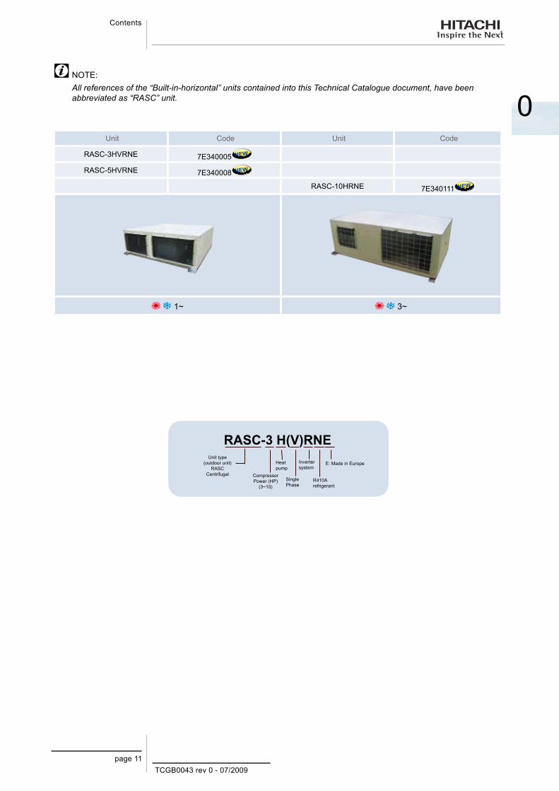
0 NOTE:
All references of the “Built-in-horizontal” units contained into this Technical Catalogue document, have been abbreviated as “RASC” unit.
Unit Code Unit Code
RASC-3HVRNE 7E340005 NEW
RASC-5HVRNE 7E340008 NEW
RASC-10HRNE 7E340111 NEW
1~ 3~
RASC-3 H(V)RNEUnit type
(outdoor unit) RASC
Centrifugal Compressor Power (HP)
(3~10)R410A refrigerant
Heat pump
Single Phase
Inverter system
E: Made in Europe
TCGB0043 rev 0 - 07/2009page 12
Contents
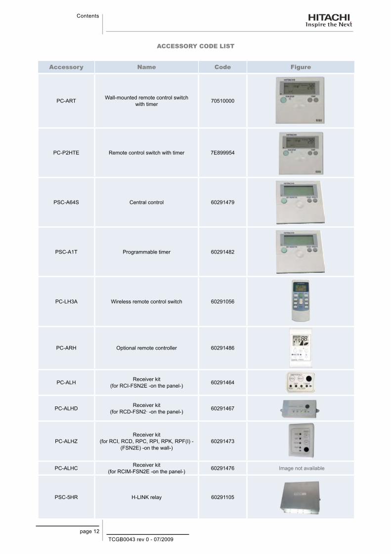
ACCESSORY CODE LIST
Accessory Name Code Figure
PC-ART Wall-mounted remote control switch with timer 70510000
PC-P2HTE Remote control switch with timer 7E899954
PSC-A64S Central control 60291479
PSC-A1T Programmable timer 60291482
PC-LH3A Wireless remote control switch 60291056
PC-ARH Optional remote controller 60291486
PC-ALH Receiver kit (for RCI-FSN2E -on the panel-) 60291464
PC-ALHD Receiver kit (for RCD-FSN2· -on the panel-) 60291467
PC-ALHZReceiver kit
(for RCI, RCD, RPC, RPI, RPK, RPF(I) - (FSN2E) -on the wall-)
60291473
PC-ALHC Receiver kit (for RCIM-FSN2E -on the panel-) 60291476 Image not available
PSC-5HR H-LINK relay 60291105

TCGB0043 rev 0 - 07/2009page 13
Contents
0Accessory Name Code Figure
PCC-1A Optional function connector 60199286
PRC-10E1 2-pin extension cord 7E790211
PRC-15E1 2-pin extension cord 7E790212
PRC-20E1 2-pin extension cord 7E790213
PRC-30E1 2-pin extension cord 7E790214
THM-R2AE Remote sensor (THM4) 7E799907
HARC-BXE (A) Lonwork BMS Interface (7 inputs up to 6 units) 60290874
HARC-BXE (B) Lonwork BMS Interface (4 inputs up to 32 units) 60290875
HARC MOD BUS
Integration with installations with intelligent control
(Building Management System) Gateway Interface
to LON-WORKS BMS systems.
70513200
HC-A64BNP
Integration with installations with intelligent control
(Building Management System) Gateway Interface
to BAC NET BMS systems.
60xxxx11
CSNET-WEB (V3) Control System 7E891938
TS001 WEB SCREEN 15-inch touch-screen display 7E891935
PCA-1IO Integration of teams into H-Link 70519000
HC-A160 SMS SMS alarm warning device 70519100
TCGB0043 rev 0 - 07/2009page 14
Contents
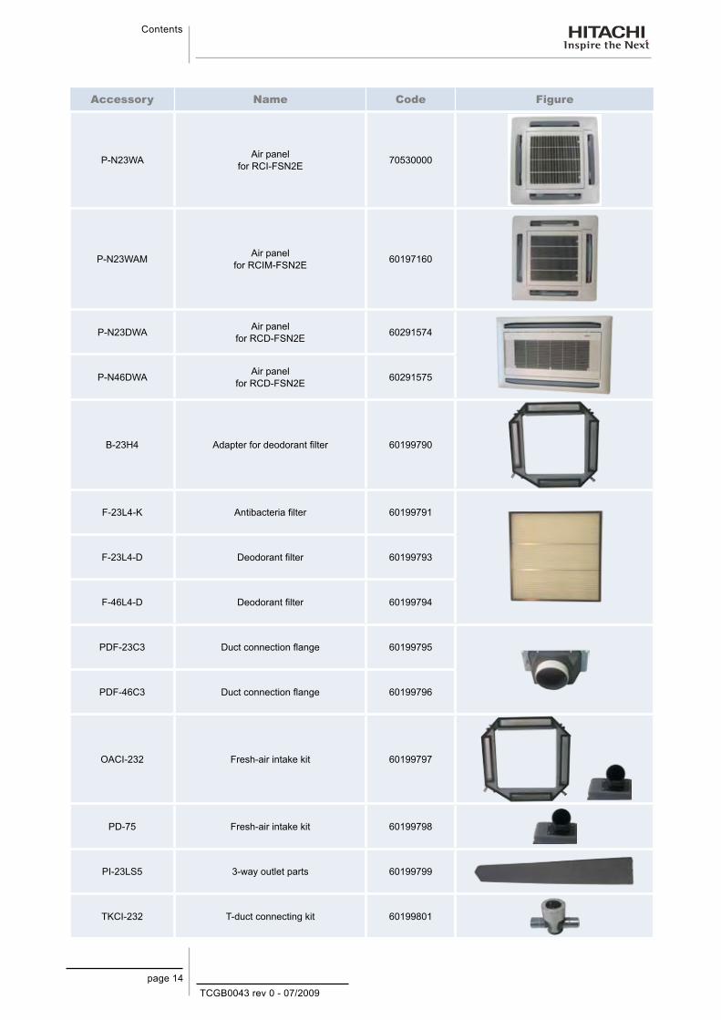
Accessory Name Code Figure
P-N23WA Air panel for RCI-FSN2E 70530000
P-N23WAM Air panel for RCIM-FSN2E 60197160
P-N23DWA Air panel for RCD-FSN2E 60291574
P-N46DWA Air panel for RCD-FSN2E 60291575
B-23H4 Adapter for deodorant filter 60199790
F-23L4-K Antibacteria filter 60199791
F-23L4-D Deodorant filter 60199793
F-46L4-D Deodorant filter 60199794
PDF-23C3 Duct connection flange 60199795
PDF-46C3 Duct connection flange 60199796
OACI-232 Fresh-air intake kit 60199797
PD-75 Fresh-air intake kit 60199798
PI-23LS5 3-way outlet parts 60199799
TKCI-232 T-duct connecting kit 60199801

TCGB0043 rev 0 - 07/2009page 15
Contents
0Accessory Name Code Figure
TE-03N Branch pipe 70800007
TE-04N Branch pipe 70800008
TE-05N Branch pipe 70800009
TE-08N Branch pipe 70800003
TE-10N Branch pipe 70800004
QE-810N Branch pipe 70800006

TCGB0043 rev 0 - 07/2009page 17
System description
I n t r o d u c t i o n
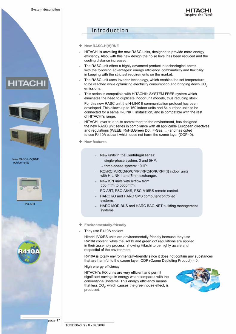
New RASC-H(V)RNE ¡HITACHI is unveiling the new RASC units, designed to provide more energy −efficiency. Also, with this new design the noise level has been reduced and the cooling distance increased. The RASC unit offers a highly advanced product in technological terms −with the following advantages: energy efficiency, combinability and flexibility, in keeping with the strictest requirements on the market.The RASC unit uses Inverter technology, which enables the set temperature −to be reached while optimizing electricity consumption and bringing down CO2 emissions.This series is compatible with HITACHI's SYSTEM FREE system which −eliminates the need to duplicate indoor unit models, thus reducing stock.For this new RASC unit the H-LINK II communication protocol has been −developed. This allows up to 160 indoor units and 64 outdoor units to be connected for a same H-LINK II installation, and is compatible with the rest of HITACHI's range.HITACHI, ever true to its commitment to the environment, has designed −the new RASC unit series in compliance with all applicable European directives and regulations (WEEE, RoHS,Green Dot, F-Gas, ...) and has opted to use R410A coolant which does not harm the ozone layer (ODP=0).
New features ¡
Environmentally-friendly ¡They use R410A coolant. −
Hitachi IVX/ES units are environmentally-friendly because they use R410A coolant, while the RoHS and green dot regulations are applied in their assembly process, showing Hitachi to be highly aware and respectful of the environment.
R410A is totally environmentally-friendly since it does not contain any substances that are harmful to the ozone layer, ODP (Ozone Depleting Product) = 0.
High energy efficiency −
HITACHI's IVX units are very efficient and permit significant savings in energy when compared with the conventional systems. This energy efficiency means that less CO2, which causes the greenhouse effect, is produced.
New units in the Centrifugal series: −
single-phase system: 3 and 5HP; −
three-phase system: 10HP −
RCI/RCIM/RCD/RPC/RPI/RPC/RPK/RPF(I) indoor units −with H-LINK II and 7mm exchanger.New KPI units with airflow from −500 m3/h to 3000m3/h.PC-ART, PSC-A64S, PSC-A16RS remote control. −
HARC I/O and HARC SMS computer-controlled −systems.HARC MOD BUS and HARC BAC-NET building management −systems.
PC-ART
New RASC-H(V)RNE outdoor units


TCGB0043 rev 0 - 07/2009
1
Features andbenefits of RASC units
page 19
1. F e a t u r e s a n d B e n e f i t s o f R A S C u n i t s
This chapter describes the features and benefits of the new RASC series outdoor unit. The system's flexibility and modularity offer you the complete solution for your air conditioning requirements.
Contents
1. Features and benefits of RASC units ..................................................191.1. General features and benefits ......................................................................................20
1.2.1. Non visible installation & large external static pressure range availability ...........................221.2.2. Expanded range “NEW” 3HP unit. .......................................................................................221.2.3. Compact size & low height ...................................................................................................221.2.4. Energy saving ......................................................................................................................231.2.5. Confort .................................................................................................................................231.2.6. Low temperature operation ..................................................................................................231.2.6. Enlarged system configuration (H-LINK II application) ........................................................241.2.7. Expanded max. pipe length .................................................................................................241.2.8. Hitachi high reliable Scroll DC-Inverter Compressor ............................................................241.2.9. Improved Refrigerant Cycle .................................................................................................251.2.10. Flexible inlet and outlet air option .......................................................................................251.2.11. High indoor units combinability and installation flexibility ...................................................251.2.12. Compatibility .......................................................................................................................25
1.3. Wide Range of Accessories.........................................................................................26
1.3.1. Complete Remote Control Range ........................................................................................26
1.4. Easy and Flexible Electrical Installation .......................................................................30
1.5. Easy and Flexible Control Connection (Central Station, Interficie BMS, CSNET WEB) ............................................................31
1.6. Start-up Benefits ...........................................................................................................31
1.6.1. Automatic Start-up Test ........................................................................................................31
1.7. Maintenance Benefits ...................................................................................................32

TCGB0043 rev 0 - 07/2009page 20
Features andbenefits of RASC units
1.1. General features and benefitsRASC units ¡
Non visible installation & large external static pressure range availability –
Expanded range “New” 3 HP unit –
Compact size and low height –
Energy saving –
Confort –
Low temperature operation –
Enlarged system configuration (H-Link II application) –
Expanded maximum pipe length –
Hitachi high reliable scroll DC Inverter compressor –
Improved refrigerant cycle –
Flexible inlet and outlet air option –
High indoor units compatibility and installation flexibility –
Compatibillity (indoor units FSN1E & FSN2E) –
Outdoor Units
Capacity (HP)
3 5 10
RA
SC
-HV
RN
E 1
~R
AS
-HR
NE
3N
~

TCGB0043 rev 0 - 07/2009
1
Features andbenefits of RASC units
page 21
Unit of constant capacity
Indoor Unit ¡More efficient, use of a 7mm copper pipe exchanger. –
Indoor Units
Capacity (HP)
1.5 2.5 3 4 5 6 10
SY
STE
M F
RE
E
Duc
t
low
Duc
t for
hot
els
Cas
sette
4-w
ay mini
2-w
ayW
all
Cei
ling
Floo
r With
cas
ing
With
out c
asin
g

TCGB0043 rev 0 - 07/2009page 22
Features andbenefits of RASC units
1.2.1. Non visible installation & large external static pressure range availability
Suitable application for both business and household where it is not possible to –place the outdoor unit outside the building.To fulfil legislation and local regulations regarding air conditioning units –installation.Ducts flexibility allows to adapt each installation depending on each particular –need.
Example of no duct installation Example of installation with ducts
1.2.2. Expanded range “NEW” 3HP unit.
BEFORE (fix-speed compressor) AFTER (DC-Inverter compressor)
1.2.3. Compact size & low height
430 mm
1300 mm1250 mm
640 mm
985 mm1850 mm
- Low Height units → -125 mm reductionW x H x D: 1250 x 1300 x 430 (BEFORE model: 1312 x 555 x 835)
Foot Print: 1,6 m2
Volume: 0,7 m3
Weight (3HP): 168 kg.Weight (5HP): 176 kg.
- Weight reduction → -48 kg reduction)W x H x D: 1850 x 640 x 985 (BEFORE model: 2050 x 640 x 930)
Foot Print: 1,8 m2
Volume: 1,2 m3
Weight (10HP): 262 kg.

TCGB0043 rev 0 - 07/2009
1
Features andbenefits of RASC units
page 23
1.2.4. Energy savingElectrical input power is reduced by means of compressor’s frequency control –(H(V)RNE series instead of ON-OFF fix-speed compressor (HNE series)).
Fix speed control
DC-Inverter control
High power operation Energy saving operation
Com
pres
sor (
rpm
)
In case of existing machines with constant speed, repeated turning on and off wastes energy.
Compressor ON(fix speed control)
Compressor OFF(fix speed control)
Hz control(DC-Inverter control)
Hz Max(DC-Inverter control)
DC-Inverter control allows to reduce the annual electricity consumption with –a saving of aprox. 25% (depending on each weather conditions) compared to previous fix-speed compressor series.
25% down
Electricity consumption per
year
1.2.5. ConfortSet temperature is rapidly reached and stabilised by smooth frequency control –
DC-Inverter control
Fix speed control
Set temperature
Time
Roo
m te
mpe
ratu
re
Hz control(DC-Inverter control)
Hz Max(DC-Inverter control)
Thermo OFF (fix speed
compressor)
(fix speed compressor) Thermo ON
1.2.6. Low temperature operation
Extended Working temperature range in Heating operation. –
Wide working range including as standard RASC unit Fan Control in cooling –mode for operating at low ambient temperature.
external temp
external temp
external temp
seriesseries “H(V)RNE”“HNE”

TCGB0043 rev 0 - 07/2009page 24
Features andbenefits of RASC units
1.2.6. Enlarged system configuration (H-LINK II application)
The System Configuration has greatly improved up to 64 refrigerant cycles. –
UTOPIA single split unit, a maximum of 64 indoor units can be connected in –one H-LINK II.The maximum number of indoor units to be connected has increased up to 160 –units. Thus large-scale installations can be done.In the case of simultaneous operation UTOPIA twin, triple and quad indoor –units will not need remote control cable among indoor units.
Items H-LINK H-LINK II
Maximum refrigerant cycle number 16 64
Indoor unit address range per 1 refrigerant cycle 0 to 15 0 to 63
Maximum connectable indoor unit 128 160
Maximum number of equipments 145 200
1.2.7. Expanded max. pipe length
Pipe length increase (+20m) for the 10HP unit. −
Items RASC-10HNE RASC-10HRNE
Max. Pipe Length (m.) 30 50
1.2.8. Hitachi high reliable Scroll DC-Inverter CompressorImproved Performance at Intermediate Season. –
High efficiency at low speed has been significantly improved by adopting new –compressor mechanism and the DC-Inverter motor. Horizontal DC-Inverter Compressor configuration for (3/5)HP → as a result: –“low height” units.
Special horizontal DC-Inverter compressor
configuration.
Compressor DC-Control –Standard equipment of power-saving technology Other facility/multiple air conditioners are not limited to use during on-peak energy hours thanks to demand control function.
IPM (Intelligent Power Module)*Only for RASC-(3/5)HVRNE
ISPM (Inverter System Power Module)*Only for RASC-10HRNE
New Compressor mechanism
(Release Valve)
New DC-Inverter motor
(Concentrated Winding)

TCGB0043 rev 0 - 07/2009
1
Features andbenefits of RASC units
page 25
1.2.9. Improved Refrigerant Cycle
Heat exchanger with optimised piping (ø9.53mm – → ø7mm)Accordion Aluminium Fin with low Pressure Loss (20% reduction of Heat –Exchanger resistance)
electronic expansion valve
Single-phase receiver
Stop valve of the liquid pipe
Indoor unit heat exchanger
Electronic expansion valve
Rear side Front side
AirAir
Increase in enthalpy due to use of the supercooling circuit
Exchanger duct 7mm in diameter
Compressor Highly-efficient DC INVERTER
Air
New fin with low pressure loss20% reduced
Draft resistance
1.2.10. Flexible inlet and outlet air option
Side panels and grilles can be changed depending on each installation needs.
Inlet air option Outlet air option (RASC-10 only)
Change Panel
(Factory supplied) (Option)
(View from top)
Change Panel
Fan motor shall be rotated as it is indicated
1.2.11. High indoor units combinability and installation flexibility
Following the Utopia DC Inverter concept, the new RASC-(3/5/10) DC-Inverter units accepts the combination with different types of Hitachi Indoor units.
4-Way Cassette type
2-Way Cassette
typeCeilling type In-the-Ceiling
type Wall type Floor typeFloor
Concealed type
RCIM-1.5FSN2 -- -- RPIM-1.5FSN2E -- -- --RCI-1.5FSN2E RCD-1.5FSN2 -- RPI-1.5FSN2E RPK-1.5FSN2M RPF-1.5FSN2E RPFI-1.5FSN2ERCI-2.5FSN2E RCD-2.5FSN2 RPC-2.5FSN2E RPI-2.5FSN2E RPK-2.5FSN2M RPF-2.5FSN2E RPFI-2.5FSN2ERCI-3.0FSN2E RCD-3.0FSN2 RPC-3.0FSN2E RPI-3.0FSN2E RPK-3.0FSN2M -- --RCI-4.0FSN2E RCD-4.0FSN2 RPC-4.0FSN2E RPI-4.0FSN2E RPK-4.0FSN2M -- --RCI-5.0FSN2E RCD-5.0FSN2 RPC-5.0FSN2E RPI-5.0FSN2E -- -- --RCI-6.0FSN2E RCD-6.0FSN2 RPC-6.0FSN2E RPI-6.0FSN2E -- -- --
-- -- -- RPI-10.0FSN2E -- -- --
The available cycles configuration are shown in the next table:
3HP 5HP 10HP
Single 3.0 5.0 10.0
Twin 1.5 1.5 2.5 2.55.0 5.04.0 6.0
Quad. -- -- -- -- 2.5 2.5 2.5 2.5
1.2.12. CompatibilityNew RASC-(3/5/10) DC-Inverter series are compatible with all FSN(1/2) , FSN(1/2)E and FSN(1/2)M indoor units
TE-N multikit
QE-810N distributor
Multikits and distributors example supplied by HITACHI:

TCGB0043 rev 0 - 07/2009page 26
Features andbenefits of RASC units
1.3. Wide Range of AccessoriesAll the units have a large set of accessories that facilitate installation, operation and maintenance.
These accessories are designed to improve and adapt the unit to the type of installation the system needs, always keeping in mind the parameters of quality that the system requires.
These accessories are of type:
Remote control switches –
Panels –
Filters –
Multikits –
1.3.1. Complete Remote Control RangeHITACHI has three different remote control systems that can be used with DC INVERTER outdoor units.
Individual control systems –
Centralized control systems –
Computer control systems –
HITACHI also has interface equipment to integrate its machines in installations with intelligent control or BMS (Building Management System).
Individual Control Systems ¡PC-ART
Remote control switch with timer:
LCD display. –
4 timer settings per week. –
Optional functions like locking, energy saving, and intelligent room –temperature maintenance.Automatic testing to solve problems that provides information continually –with an alarm code.Access to all function settings for the indoor units. –
Thermostat function available. –
Details of all settings are given on screen, facilitating system functionality –checking.If there are problems with the power supply the backup functions keep –the timer working.Indoor unit control groups (from 1 to 16 units in each group). –
PC-LH3A
A wireless remote control switch that removes the need for wiring and provides simple one-touch operation. Permits control of two or more units simultaneously.
PC-ART Wall-mounted remote
control switch with timer
PC-LH3A Wireless Remote
Control Switch

TCGB0043 rev 0 - 07/2009
1
Features andbenefits of RASC units
page 27
PC-ARH
Smaller remote control than conventional remote controls. Its main features are setting the unit's temperature and operating mode. It is ideal for facilities such as hotels due to its user-friendliness.
Two remote control switches or a group control (for a maximum of 16 units) can be used in a similar way to the standard remote control switch.
When a problem occurs, an alarm code immediately shows the details of the error.
There are also optional functions such as limiting the operating mode, limiting the maximum temperature in heating/cooling mode, selecting the fan speed, etc.
PSC-A1T
Programmable timer used to set operating schedules for air conditioning systems.
Along with the PSC-A64S and PC-ART controllers, the air conditioners they control can be operated according to the schedule below:
The timer can be set at 7-day intervals and operation/stop can be set –three times a day.The remote control switch can be disabled during the OFF time –(when used with PSC- A64S and PC-ART).Two types of weekly schedule (A and B) can be set and easily changed –for summer and winter operation.Settings are all digitally displayed, allowing operations and settings –to be easily checked.
The power failure backup function prevents the timer from stopping because of a power failure (even if it lasts for weeks).
Centralized Control Systems ¡PSC-A64S (central control)
A group of up to 64 remote control switches can be connected to –an H-LINK II to control up to 128 indoor units.Up to 8 PSC-A64S units can be connected to an H-LINK II. –
In addition to the basic functions, operation mode and temperature –setting, it is possible to set the air flow or auto louver.When a problem occurs, an alarm code immediately shows the details –of the error.A signal terminal to provide external inputs is supplied as standard –which control the following functions:On/Off –
Emergency stop –
Central operation output –
Central alarm output –
PSC-A16RS (central control)
Up to 16 indoor units can be connected. –
User-friendly. –
PSC-A1TTimer
PC-ARH Basic wired remote
control switch
PSC-A64SCentral station
TCGB0043 rev 0 - 07/2009page 28
Features andbenefits of RASC units
Computer Control Systems ¡CSNET-WEB
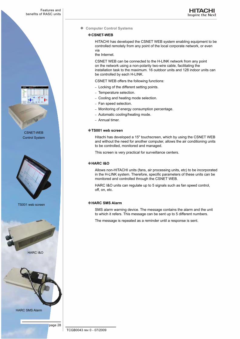
HITACHI has developed the CSNET WEB system enabling equipment to be controlled remotely from any point of the local corporate network, or even via the Internet.
CSNET WEB can be connected to the H-LINK network from any point on the network using a non-polarity two-wire cable, facilitating the installation task to the maximum. 16 outdoor units and 128 indoor units can be controlled by each H-LINK.
CSNET WEB offers the following functions:
Locking of the different setting points. –
Temperature selection. –
Cooling and heating mode selection. –
Fan speed selection. –
Monitoring of energy consumption percentage. –
Automatic cooling/heating mode. –
Annual timer. –
TS001 web screen
Hitachi has developed a 15" touchscreen, which by using the CSNET WEB and without the need for another computer, allows the air conditioning units to be controlled, monitored and managed.
This screen is very practical for surveillance centers.
HARC I&O
Allows non-HITACHI units (fans, air processing units, etc) to be incorporated in the H-LINK system. Therefore, specific parameters of these units can be monitored and controlled through the CSNET WEB.
HARC I&O units can regulate up to 5 signals such as fan speed control, off, on, etc.
HARC SMS Alarm
SMS alarm warning device. The message contains the alarm and the unit to which it refers. This message can be sent up to 5 different numbers.
The message is repeated as a reminder until a response is sent.
CSNET-WEBControl System
TS001 web screen
HARC SMS Alarm
HARC I&O
TCGB0043 rev 0 - 07/2009
1
Features andbenefits of RASC units
page 29
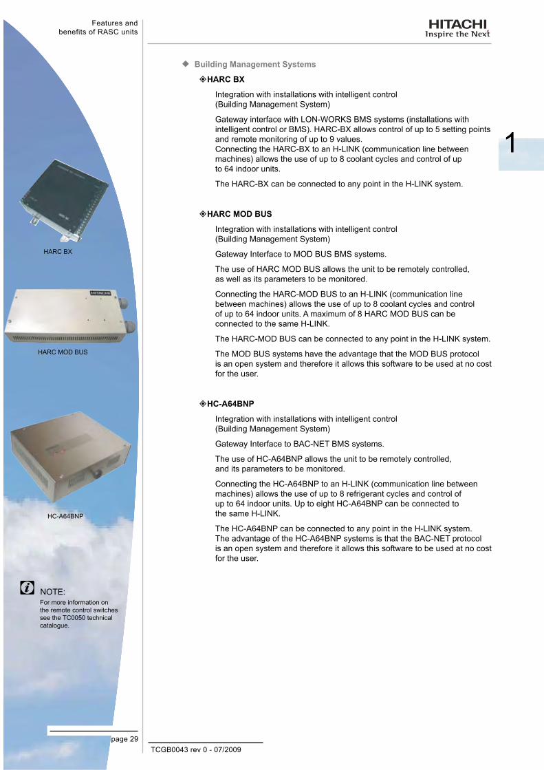
Building Management Systems ¡HARC BX
Integration with installations with intelligent control (Building Management System)
Gateway interface with LON-WORKS BMS systems (installations with intelligent control or BMS). HARC-BX allows control of up to 5 setting points and remote monitoring of up to 9 values. Connecting the HARC-BX to an H-LINK (communication line between machines) allows the use of up to 8 coolant cycles and control of up to 64 indoor units.
The HARC-BX can be connected to any point in the H-LINK system.
HARC MOD BUS
Integration with installations with intelligent control (Building Management System)
Gateway Interface to MOD BUS BMS systems.
The use of HARC MOD BUS allows the unit to be remotely controlled, as well as its parameters to be monitored.
Connecting the HARC-MOD BUS to an H-LINK (communication line between machines) allows the use of up to 8 coolant cycles and control of up to 64 indoor units. A maximum of 8 HARC MOD BUS can be connected to the same H-LINK.
The HARC-MOD BUS can be connected to any point in the H-LINK system.
The MOD BUS systems have the advantage that the MOD BUS protocol is an open system and therefore it allows this software to be used at no cost for the user.
HC-A64BNP
Integration with installations with intelligent control (Building Management System)
Gateway Interface to BAC-NET BMS systems.
The use of HC-A64BNP allows the unit to be remotely controlled, and its parameters to be monitored.
Connecting the HC-A64BNP to an H-LINK (communication line between machines) allows the use of up to 8 refrigerant cycles and control of up to 64 indoor units. Up to eight HC-A64BNP can be connected to the same H-LINK.
The HC-A64BNP can be connected to any point in the H-LINK system. The advantage of the HC-A64BNP systems is that the BAC-NET protocol is an open system and therefore it allows this software to be used at no cost for the user.
HARC BX
HARC MOD BUS
HC-A64BNP
For more information on the remote control switches see the TC0050 technical catalogue.
NOTE:

TCGB0043 rev 0 - 07/2009page 30
Features andbenefits of RASC units
1.4. Easy and Flexible Electrical InstallationInterconnection of Units Via the New H-LINKII ¡The units interconnect via a bus called H-LINKII, consisting of 2 non-polarity cables and accepting lengths of up to 1,000m. Accessories are available if required to increase this length to 5,000m.
Up to 160 Indoor Units Connected to Each Circuit. ¡Each H-LINKII bus can communicate up to 160 indoor units. Taking into account the absence of polarity and the length of line permitted, the flexibility of the interconnection between the machines is very high. This lets you, for example, connect the H-LINKII of a cooling system's indoor unit to the H-LINKII of another system's indoor unit.
H-LINKII BUS
Specifications:Transmission cable: 2-wirePolarity of transmission cable: Non-polar wire
Maximum outdoor units 64 units per H-LINKII systemMaximum indoor units 160 units per H-LINKII systemMaximum number of equipment units 200
Maximum wiring length: Total 1,000m (including CSNET WEB)
Recommended cable: Shielded twisted pair cable or shielded pair cable, over 0.75mm² (equivalent to KPEV-S)
Voltage: DC5V
In the case of double, triple and quadruple systems the interior units can be controlled using a single remote control switch without having to join them with an operating cable for the remote control.
An operating cable is not required for using the remote control switch
Operation wiring
Example of H-Link II system:
When using the H-LINKII system, DIP switches have to be adjusted. If the DIP switches are not set or set incorrectly, an alarm may occur due to transmission failure. Total wiring length for the remote control switch can be extended to up to 5,000m. If total wiring length is less than 30m, it is possible to use the normal wiring (0.3mm²).The H-LINKII system provides maximum flexibility for system design; installation is easy, and total costs are reduced. Furthermore, it can be controlled centrally by connecting CSNET WEB to H-LINKII wiring located in the room next to the room where CSNET WEB is installed.You can also control the installation by Internet via CSNET WEB
NOTES:
TCGB0043 rev 0 - 07/2009
1
Features andbenefits of RASC units
page 31
1.5. Easy and Flexible Control Connection (Central Station, Interficie BMS, CSNET WEB)
No Polarity ¡Thanks to the absence of polarity, any centralized control can be connected directly to the H-LINKII bus, which means that special lines are not needed.
Auto-Configuration ¡Aside from the customized configuration, the control systems are also auto-configurable; for example, they have the capacity of interpreting the type of machine they are connected to, and detecting the type of indoor unit or its power.
1.6. Start-up Benefits1.6.1. Automatic Start-up Test
There are three set-up modes:
Test run –
Test run from the remote control switch –
Test run from the outdoor unit –
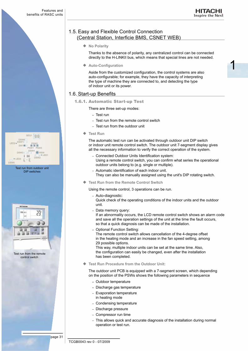
Test Run ¡The automatic test run can be activated through outdoor unit DIP switch or indoor unit remote control switch. The outdoor unit 7-segment display gives all the necessary information to verify the correct operation of the system.
Connected Outdoor Units Identification system: –Using a remote control switch, you can confirm what series the operational outdoor units belong to (e.g. single or multiple).Automatic identification of each indoor unit. –They can also be manually assigned using the unit's DIP rotating switch.
Test Run from the Remote Control Switch ¡Using the remote control, 3 operations can be run.
Auto-diagnostic: –Quick check of the operating conditions of the indoor units and the outdoor unit.Data memory query: –If an abnormality occurs, the LCD remote control switch shows an alarm code and save all the operation settings of the unit at the time the fault occurs, so that a quick diagnosis can be made of the installation.Optional Function Setting: –The remote control switch allows cancellation of the 4-degree offset in the heating mode and an increase in the fan speed setting, among 29 possible options. This way, multiple indoor units can be set at the same time. Also, the configuration can easily be changed, even after the installation has been completed.
Test Run Procedure from the Outdoor Unit: ¡The outdoor unit PCB is equipped with a 7-segment screen, which depending on the position of the PSWs shows the following parameters in sequence
Outdoor temperature –
Discharge gas temperature –
Evaporation temperature –in heating modeCondensing temperature –
Discharge pressure –
Compressor run time –
This allows quick and accurate diagnosis of the installation during normal –operation or test run.
Test run from the remote control switch
Test run from outdoor unit DIP switches
TCGB0043 rev 0 - 07/2009page 32
Features andbenefits of RASC units
1.7. Maintenance Benefits
Minimum Maintenance ¡The RASC units have been designed in line with Hitachi's philosophy, guaranteeing great reliability and robustness and reducing maintenance to a minimum.
Easy Accessibility ¡The RASC system components are easily accessible. You can access all of the unit's components to perform the necessary operations through a simple cover. The entire system is designed for maintenance operations to be easy and simple.
Alarm information in the remote control switch through the PCB ¡Alarm signals can be received through the remote control switches (whether individual or centralized), the CSNET WEB software, or via the electric plate of the outdoor unit, thus facilitating maintenance work.
Alarm Codes ¡The alarms are grouped by elements within the system in order to facilitate maintenance work and optimize the fitter's job

TCGB0043 rev 0 - 07/2009page 33
General Data
2. G e n e r a l D a t a
2
This chapter offers a summary of the most important features of the RASC-H(V)RNE series.
Contents
2. General Data ...........................................................................................................332.1. RASC – General Data .......................................................................................................................... 34
2.1.1. RASC - HVRNE Outdoor Units ....................................................................................................................... 342.1.2. RASC - HRNE Outdoor Units .......................................................................................................................... 352.1.3. Fan and Exchanger ......................................................................................................................................... 362.1.4. Compressor ..................................................................................................................................................... 37

TCGB0043 rev 0 - 07/2009page 34
General data
2.1. RASC – General Data
2.1.1. RASC - HVRNE Outdoor Units
RASC MODEL RASC-3HVRNE RASC-5HVRNE
Electrical power supply 1~ 230V 50Hz
Nominal cooling capacity kW 7.10 12.50
Nominal heating capacity kW 8.00 14.00Energy efficiency in cooling mode (EER) kW/kW 2.90 2.71
Energy efficiency coefficient in heating mode (COP) kW/kW 3.10 3.10
Color (Munsell code) - Natural Grey (1.0Y8.5/0.5)
Sound pressure level (cool/heat) dB(A) 46/46 55/56
Sound power level dB(A) 61 71
External dimensions
Height mm 430 430
Width mm 1250 1250
Depth mm 1300 1300
Net weight kg 168 176
Ref
riger
ant
Type - R410A
Ref. Flow control - Microprocessor-controlled expansion valve
Com
pres
sor Type - DC inverter driven
Qty. - 1 1
Power kW 1.38 2.50
Out
door
fan
Type - Centrifugal Fan
Qty. - 2 2
Air flow rate m³/min 40 65
Heat exchanger - Multi-pass cross-finned tube
Power W 350 950
Ref
riger
ant
Pip
es
Type - Flare-nut connection (factory supplied)
SizeLiquid piping
mm (in)
Ø9.53 (3/8)
Ø9.53 (3/8)
Gas piping mm (in)
Ø15.88 (5/8)
Ø15.88 (5/8)
Condensate drain pipe size mm Ø25 OD Ø25 OD
Refrigerant charge Kg 2.80 4.00
Maximum electrical current A 28 37
Packaging measurements m³ 1.04 1.04OD: Outer Diameter
NOTE:1. The nominal cooling and heating capacity is
the combined capacity of the RASC system, and is based on EN14511.
2. The sound pressure level is based on following conditions:
1.5 meters beneath the unit (With duct). -Voltage of the power source is 230V. -
The above was measured in an anechoic chamber, so reflected sound should be taken into consideration when installing the unit.
3. In night mode, the noise level decreases 4dB(A).4. The COP and EER have been calculated with
RCI-FSN2E model indoor units.
Operating Conditions Cooling Heating
Indoor air inlet temperature
DB 27.0°C 20.0°CWB 19.0°C -
Outdoor air inlet temperature
DB 35.0°C 7.0°CWB - 6.0°C
Piping length: 7.5 meters; Piping lift: 0 meters DB: dry bulb; WB: wet bulb

TCGB0043 rev 0 - 07/2009page 35
General Data
2
2.1.2. RASC - HRNE Outdoor Units
RASC MODEL RASC-10HRNE
Electrical power supply 3N~ 400V 50Hz
Nominal cooling capacity kW 23.00
Nominal heating capacity kW 25.00
Energy efficiency in cooling mode (EER) kW/ kW 2.71
Energy efficiency coefficient in heating mode (COP) kW/ kW 2.91
Color (Munsell code) - Natural Grey (1.0Y8.5/0.5)
Sound pressure level (cool/heat) dB(A) 68
Sound power level dB(A) 83
Outside measurements
Height mm 640Width mm 1850Depth mm 985
Net weight+- kg 262
Ref
riger
ant
Type - R410A
Ref. Flow control - Microprocessor-controlled expansion valve
Com
pres
sor
Type - DC inverter driven
Qty. un. 1
Power kW 4.00
Fan
Type - Centrifugal Fan
Qty. un. 1
Air flow rate m³/min 110
Heat exchanger un. 1
Power W 1500
Ref
riger
ant
Pip
es
Type - Flare nut / Flange connection
SizeLiquid piping mm
(in) Ø12.7 (1/2)
Gas piping mm (in) Ø25.40 (1/1)
Condensate drain pipe size mm Ø25 OD
Refrigerant charge Kg 9.00
Maximum electrical current A 40
Packaging measurements m³ 1.80OD: Outer Diameter
NOTE:1. The nominal cooling and heating capacity is
the combined capacity of the RASC system, and is based on EN14511.
2. The sound pressure level is based on following conditions:
1.5 meters beneath the unit (With duct). -
Voltage of the power source is 400V. -
The above was measured in an anechoic chamber, so reflected sound should be taken into consideration when installing the unit.
3. In night mode, the noise level decreases 4dB(A).4. The COP and EER have been calculated with
RCI-FSN2E model indoor units.
Operating Conditions Cooling Heating
Indoor air inlet temperature
DB 27.0°C 20.0°CWB 19.0°C -
Outdoor air inlet temperature
DB 35.0°C 7.0°CWB - 6.0°C
Piping length: 7.5 meters; Piping lift: 0 metersDB: dry bulb; WB: wet bulb
TCGB0043 rev 0 - 07/2009page 36
General data
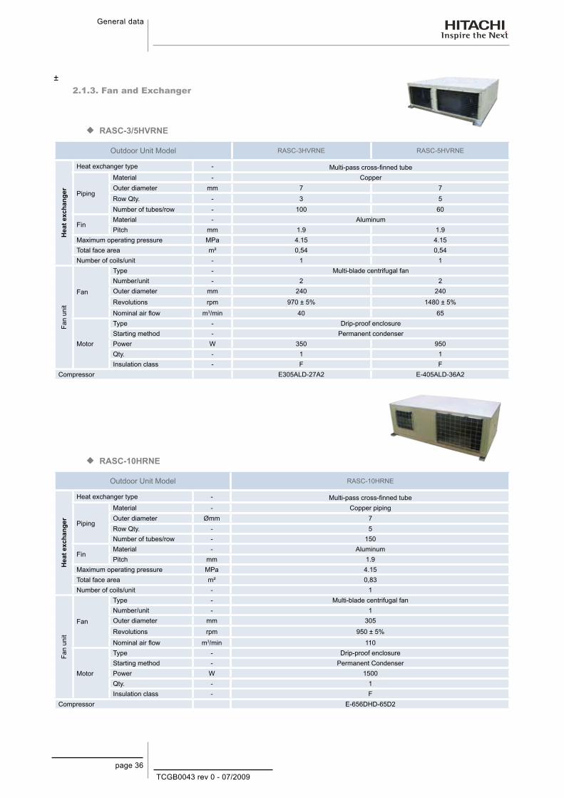
±2.1.3. Fan and Exchanger
RASC-3/5HVRNE ¡
Outdoor Unit Model RASC-3HVRNE RASC-5HVRNE
Hea
t exc
hang
er
Heat exchanger type - Multi-pass cross-finned tube
Piping
Material - CopperOuter diameter mm 7 7Row Qty. - 3 5Number of tubes/row - 100 60
FinMaterial - AluminumPitch mm 1.9 1.9
Maximum operating pressure MPa 4.15 4.15Total face area m² 0,54 0,54Number of coils/unit - 1 1
Fan
unit
Fan
Type - Multi-blade centrifugal fanNumber/unit - 2 2Outer diameter mm 240 240
Revolutions rpm 970 ± 5% 1480 ± 5%
Nominal air flow m3/min 40 65
Motor
Type - Drip-proof enclosureStarting method - Permanent condenserPower W 350 950Qty. - 1 1Insulation class - F F
Compressor E305ALD-27A2 E-405ALD-36A2
RASC-10HRNE ¡
Outdoor Unit Model RASC-10HRNE
Hea
t exc
hang
er
Heat exchanger type - Multi-pass cross-finned tube
Piping
Material - Copper pipingOuter diameter Ømm 7Row Qty. - 5Number of tubes/row - 150
FinMaterial - AluminumPitch mm 1.9
Maximum operating pressure MPa 4.15Total face area m² 0,83Number of coils/unit - 1
Fan
unit
Fan
Type - Multi-blade centrifugal fanNumber/unit - 1Outer diameter mm 305
Revolutions rpm 950 ± 5%
Nominal air flow m3/min 110
Motor
Type - Drip-proof enclosureStarting method - Permanent CondenserPower W 1500Qty. - 1Insulation class - F
Compressor E-656DHD-65D2

TCGB0043 rev 0 - 07/2009page 37
General Data
2
2.1.4. Compressor
Model E305ALD-27A2 E405ALD-36A2 E656DHD-65D2
Compressor type Hermetic scroll Hermetic scroll Hermetic scroll
Pressure resistance
Discharge MPa 4.15 4.15 4.15Suction MPa 2.21 2.21 2.21
Motor Starting method - Inverter-driven Inverter-driven Inverter-driven Poles - 4 4 4Insulation class - E E E
Oil type - FVC68D FVC68D FVC68D Oil quantity L 1.2 1.2 1.9


TCGB0043 rev 0 - 07/2009page 39
Dimensional Data
3
3. D i m e n s i o n a l D a t a
This chapter shows the dimensions and minimum space required to install each unit of the RASC-H(V)RNE series.
Contents
3. Dimensional Data ................................................................................393.1. Dimensional data for RASC-H(V)RNE series ...............................................................40
3.1.1. RASC-3/5HVRNE ................................................................................................................403.1.2. RASC-10HRNE ....................................................................................................................41

TCGB0043 rev 0 - 07/2009page 40
Dimensional Data
3.1. Dimensional data for RASC-H(V)RNE series
3.1.1. RASC-3/5HVRNE
Units in: mm
No. Description Remarks1 Air inlet2 Air outlet3 Electrical box cover4 Electrical box5 Fan service cover6 Stop valves cover7 Holes for wiring connections 2-Ø26
8 Drain pipe Ø26
9 Holes for fixing unit 4-Ø14
10 Refrigerant liquid pipe Flare nut: Ø9.53 (3/8”)
11 Refrigerant gas pipe Flare nut: Ø15.88 (5/8”)
12 Optional air inlet
Installation space
TCGB0043 rev 0 - 07/2009page 41
Dimensional Data
3
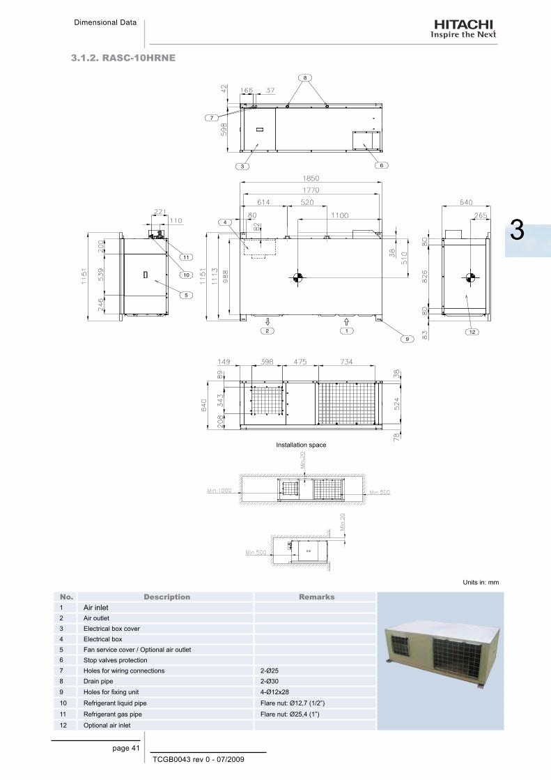
3.1.2. RASC-10HRNE
Installation space
Units in: mm
No. Description Remarks1 Air inlet2 Air outlet3 Electrical box cover4 Electrical box5 Fan service cover / Optional air outlet6 Stop valves protection7 Holes for wiring connections 2-Ø258 Drain pipe 2-Ø30
9 Holes for fixing unit 4-Ø12x28
10 Refrigerant liquid pipe Flare nut: Ø12,7 (1/2”)
11 Refrigerant gas pipe Flare nut: Ø25,4 (1”)
12 Optional air inlet


TCGB0043 rev 0 - 07/2009page 43
Capacities and Selection Data
4
4. C a p a c i t i e s a n d S e l e c t i o n D a t a
This chapter is a guide for selecting the most suitable units according to your requirements and indicates the performance data for each unit in the RASC-H(V)RNE Series.
Contenido
4. Capacities and Selection Data ............................................................434.1. RASC-H(V)RNE system selection procedure...............................................................44
4.1.1. Selection parameters ...........................................................................................................444.1.2. Selection procedure .............................................................................................................44
4.2. Combinability ................................................................................................................52
4.3. Compatibilities ..............................................................................................................52
4.4. Standard cooling and heating capacities ......................................................................53
4.5. Cooling capacity of the RASC units..............................................................................54
4.6. Heating capacity of the RASC units .............................................................................54
4.7. Correction factors .........................................................................................................55
4.7.1. Piping length correction factor ..............................................................................................554.7.2. Defrost correction factor .......................................................................................................58
4.8. Sensible heat factor (SHF) ..............................................................................................59
4.9. Fan performance .............................................................................................................60
4.10. Sound data ...................................................................................................................61
TCGB0043 rev 0 - 07/2009page 44
Capacities and Selection Data
4.1. RASC-H(V)RNE system selection procedure
RASC units are suitable for business premises and houses where the use of a conventional outdoor unit is either prohibited or impossible.
The following procedure is an example of how to select the system units and indicates how to use all the parameters indicated in this chapter.
Considering the layout of the building, the possible position of the indoor units and the air flow distribution, select the unit features that provide the greatest efficiency and comfort. Decide a position for the RASC unit that facilitates service and maintenance tasks, as well as easy refrigerant pipe installation.
4.1.1. Selection parametersTo calculate the RASC units, it will be necessary to consult and/or use a serie of parameters shown in tables and graphics presented in the different chapters of this catalogue. A summarized list is shown below:
For general information: Chapter 2. −For operating space options: Chapter 3. −For unit combinations: Section 4.2. −For capacities: Sections 4.4,4.5,4.6. −
For sensible heat factor: Section 4.8. −For correction factors: Section 4.7. −For noise characteristics: Section 4.10 −Sound data.Piping length and lift range: Chapter 7. −
In case of installation with duct (RASC with RPI indoor unit) the fan performance for duct calculations should be considered, as shown in Section 4.11. The RPI units are designed with three possible static pressure ranges in order to adapt to all installation necessities.
4.1.2. Selection procedureThe system selection procedure is as follows:
Firstly, the RASC unit is pre-selected according to the design conditions. Secondly, the combination with indoor units and their respective models is chosen. Finally, the theoretical capacity values taken from the different tables are corrected to take account of the various correction factors that exist.
This procedure is divided into two parts: cooling and heating.
TCGB0043 rev 0 - 07/2009page 45
Capacities and Selection Data
4
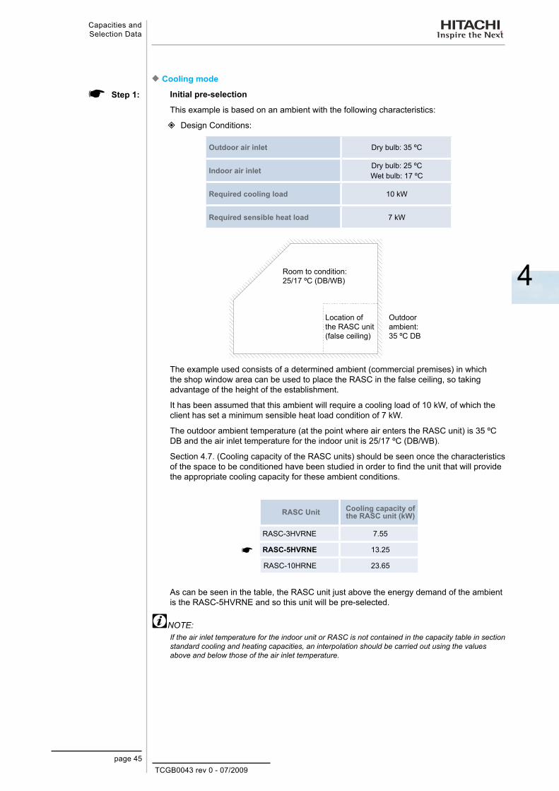
Cooling mode ¡Initial pre-selection
This example is based on an ambient with the following characteristics:
Design Conditions:
Outdoor air inlet Dry bulb: 35 ºC
Indoor air inlet Dry bulb: 25 ºC Wet bulb: 17 ºC
Required cooling load 10 kW
Required sensible heat load 7 kW
Room to condition:25/17 ºC (DB/WB)
Location of the RASC unit (false ceiling)
Outdoor ambient:35 ºC DB
The example used consists of a determined ambient (commercial premises) in which the shop window area can be used to place the RASC in the false ceiling, so taking advantage of the height of the establishment.
It has been assumed that this ambient will require a cooling load of 10 kW, of which the client has set a minimum sensible heat load condition of 7 kW.
The outdoor ambient temperature (at the point where air enters the RASC unit) is 35 ºC DB and the air inlet temperature for the indoor unit is 25/17 ºC (DB/WB).
Section 4.7. (Cooling capacity of the RASC units) should be seen once the characteristics of the space to be conditioned have been studied in order to find the unit that will provide the appropriate cooling capacity for these ambient conditions.
RASC Unit Cooling capacity of the RASC unit (kW)
RASC-3HVRNE 7.55
RASC-5HVRNE 13.25
RASC-10HRNE 23.65
As can be seen in the table, the RASC unit just above the energy demand of the ambient is the RASC-5HVRNE and so this unit will be pre-selected.
NOTE:If the air inlet temperature for the indoor unit or RASC is not contained in the capacity table in section standard cooling and heating capacities, an interpolation should be carried out using the values above and below those of the air inlet temperature.
Step 1:
TCGB0043 rev 0 - 07/2009page 46
Capacities and Selection Data
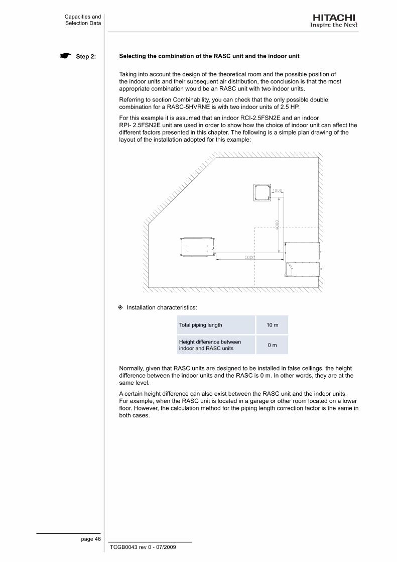
Selecting the combination of the RASC unit and the indoor unit
Taking into account the design of the theoretical room and the possible position of the indoor units and their subsequent air distribution, the conclusion is that the most appropriate combination would be an RASC unit with two indoor units.
Referring to section Combinability, you can check that the only possible double combination for a RASC-5HVRNE is with two indoor units of 2.5 HP.
For this example it is assumed that an indoor RCI-2.5FSN2E and an indoor RPI- 2.5FSN2E unit are used in order to show how the choice of indoor unit can affect the different factors presented in this chapter. The following is a simple plan drawing of the layout of the installation adopted for this example:
Installation characteristics:
Total piping length 10 m
Height difference between indoor and RASC units 0 m
Normally, given that RASC units are designed to be installed in false ceilings, the height difference between the indoor units and the RASC is 0 m. In other words, they are at the same level.
A certain height difference can also exist between the RASC unit and the indoor units. For example, when the RASC unit is located in a garage or other room located on a lower floor. However, the calculation method for the piping length correction factor is the same in both cases.
Step 2:

TCGB0043 rev 0 - 07/2009page 47
Capacities and Selection Data
4
Cooling capacity correction
The actual cooling capacity of the pre-selected unit must be calculated applying the necessary correction factors:
QC= QMC x fLC
QC: Actual cooling capacity of the RASC unit (kW)QMC: Maximum cooling capacity of the RASC unit (kW)fLC: Piping length correction factor
The maximum cooling capacity (QMC) of the RASC-5HVRNE unit is 13,25 kW.
Calculation of fLC:
Both the length of the refrigerant piping used and the height difference between the RASC unit and the indoor units directly affect the performance of the unit. This concept is quantified in the piping length correction factor.
To determine this value, it is necessary to consult section “Piping length correction factor”, where it can be seen that for the characteristics of our example (piping length of 10 metres and a height difference between the RASC unit and the indoor units of 0 metres) the piping length correction factor is 0.99
Calculation of QC:
Once the correction factors to be applied have been determined, the formula for actual cooling capacity of the unit RASC-5HVRNE can be applied:
QC= 13.25 kW x 0.99 = 13.12 kWAs can be seen, the actual cooling capacity of the RASC-5HVRNE (13.12 kW) unit is greater than the cooling load required by the ambient to be conditioned (10 kW), but before deciding that the unit is valid, it must be verified that the unit complies with the requirement for the minimum sensible heat capacity set by the client (7 kW).
NOTE:If the actual cooling capacity calculated is less than that provided by the pre-selected unit, the calculation must be done again with the unit immediately higher.
Step 3:
TCGB0043 rev 0 - 07/2009page 48
Capacities and Selection Data
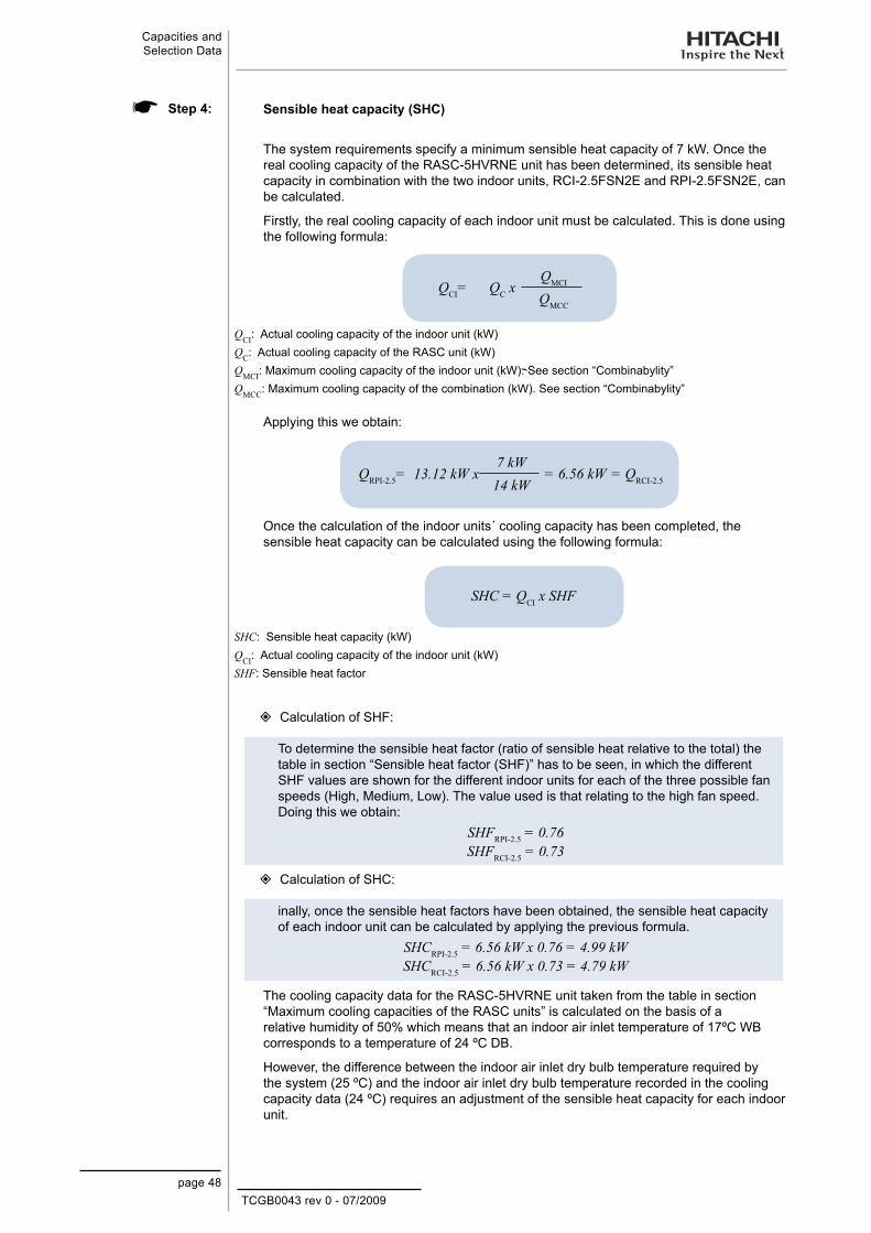
Sensible heat capacity (SHC)
The system requirements specify a minimum sensible heat capacity of 7 kW. Once the real cooling capacity of the RASC-5HVRNE unit has been determined, its sensible heat capacity in combination with the two indoor units, RCI-2.5FSN2E and RPI-2.5FSN2E, can be calculated.
Firstly, the real cooling capacity of each indoor unit must be calculated. This is done using the following formula:
QCI= QC xQMCI
QMCC
QCI: Actual cooling capacity of the indoor unit (kW)QC: Actual cooling capacity of the RASC unit (kW)QMCI: Maximum cooling capacity of the indoor unit (kW). See section “Combinabylity” QMCC: Maximum cooling capacity of the combination (kW). See section “Combinabylity”
Applying this we obtain:
QRPI-2.5= 13.12 kW x7 kW
= 6.56 kW = QRCI-2.514 kW
Once the calculation of the indoor units´ cooling capacity has been completed, the sensible heat capacity can be calculated using the following formula:
SHC = QCI x SHF
SHC: Sensible heat capacity (kW)QCI: Actual cooling capacity of the indoor unit (kW)SHF: Sensible heat factor
Calculation of SHF:
To determine the sensible heat factor (ratio of sensible heat relative to the total) the table in section “Sensible heat factor (SHF)” has to be seen, in which the different SHF values are shown for the different indoor units for each of the three possible fan speeds (High, Medium, Low). The value used is that relating to the high fan speed. Doing this we obtain:
SHFRPI-2.5 = 0.76SHFRCI-2.5 = 0.73
Calculation of SHC:
inally, once the sensible heat factors have been obtained, the sensible heat capacity of each indoor unit can be calculated by applying the previous formula.
SHCRPI-2.5 = 6.56 kW x 0.76 = 4.99 kWSHCRCI-2.5 = 6.56 kW x 0.73 = 4.79 kW
The cooling capacity data for the RASC-5HVRNE unit taken from the table in section “Maximum cooling capacities of the RASC units” is calculated on the basis of a relative humidity of 50% which means that an indoor air inlet temperature of 17ºC WB corresponds to a temperature of 24 ºC DB.
However, the difference between the indoor air inlet dry bulb temperature required by the system (25 ºC) and the indoor air inlet dry bulb temperature recorded in the cooling capacity data (24 ºC) requires an adjustment of the sensible heat capacity for each indoor unit.
Step 4:

TCGB0043 rev 0 - 07/2009page 49
Capacities and Selection Data
4
Sensible heat capacity correction (SHCC)
The following formula should be used to carry out the sensible heat correction for each indoor unit:
SHCC = SHC + (CR x (DBR - DB))
SHCC: Corrected sensible heat capacity (kW)SHC: Sensible heat capacity (kW)CR: Correction ratio due to humidity DBR: Dry bulb evaporator temperature (ºC)DB: Dry bulb evaporator temperature (ºC) for each wet bulb temperature from the table (HR = 50 %)
Calculation of CR:
The correction ratio due to humidity is shown in the table contained in section “Maximum cooling capacities of the RASC units”.
This coefficient corrects the sensible heat capacity of a unit according to the relative humidity of the air entering the indoor unit. The greater the relative humidity the lower will be the sensible heat capacity and vice versa.
The correction ratio CR for the RASC-5HVRNE unit is 0.51.
Calculation of SHC C:
Once the CR has been identified for the RASC-5HVRNE unit the corrected sensible heat capacity SHCC of the indoor unit can be calculated:
SHCC_RPI-2.5 = 4.99 kW + (0.51 x (25 - 24)) = 5.50 kWSHCC_RCI-2.5 = 4.79 kW + (0.51 x (25 - 24)) = 5.30 kW
The sensible heat capacity for the combination will be:SHCC = SHCC_RPI-2.5 + SHCC_RCI-2.5 = 5.50 kW + 5.30 kW = 10.80 kW
As can be seen, the corrected sensible heat capacity of the system (10.80 kW) is greater than the sensible heat capacity required by the ambient to be conditioned (7 kW). Therefore, it can be said that the RASC-5HVRNE unit meets the minimum cooling requirements set for the system.
In order to validate the pre-selection of the RASC-5HVRNE unit, its compliance with the minimum cooling requirements and the minimum heating requirements must be checked.
Step 5:

TCGB0043 rev 0 - 07/2009page 50
Capacities and Selection Data
Heating Mode ¡
Initial pre-selection
The heating requirements for the previous example are shown below.
Ambient conditions
Outdoor air inlet Dry bulb: 3 ºC Wet bulb: 0 ºC
Indoor air inlet Dry bulb: 20 ºC
Required heating load 11 kW
The cooling ambient studied has the following heating characteristics:
Room to condition:20 ºC DB
Location of the outdoor unit (false ceiling)
Outdoor ambient:3/0 ºC (DB/WB)
It has been assumed that the required heating load for this ambient is 11 kW.
The outdoor ambient temperature (at the point where air enters the RASC unit) is 3/0 ºC (DB/WB) and temperature of the indoor air inlet is 20 ºC DB.
Section “Maximum heating capacities of the RASC units” should be seen once the characteristics of the space to be conditioned have been studied in order to verify that the unit pre-selected for cooling provides an appropriate heating capacity for these conditions:
RASC Unit Heating capacity of the RASC unit (kW)
RASC-5HVRNE 13.55
As can be seen in the table, the RASC-5HVRNE unit provides a theoretical heating capacity greater than the heating demand required by the environment. Therefore, the calculation process can continue.
NOTE:If the unit pre-selected for cooling does not provide the heating load required by the environment the pre-selection should be changed and the next unit should be chosen.
Step 1:

TCGB0043 rev 0 - 07/2009page 51
Capacities and Selection Data
4
Heating capacity correction
The actual heating capacity of the pre-selected unit must be calculated applying the necessary correction factors:
QH= QMH x fLH x fd
QH: Actual heating capacity of the RASC unit (kW)QMH: Maximum heating capacity of the RASC unit (kW)fLH: Piping length correction factorfd: Defrosting correction factor
The maximum heating capacity (QMH) of the RASC-5HVRNE unit is 13,55 kW.
Calculation of fLH:
Consulting section “Piping length correction factor”, it can be seen that for the characteristics of our example (piping length of 10 metres and a height difference between the RASC unit and the indoor units of 0 metres) the piping length correction factor for heating mode is 0.998.
Calculation of fd:
In situations where the ambient temperature is lower than 7 ºC DB, frost may build up on the heat exchanger. In the case, the heating capacity for the unit may be reduced because of the time spent by the unit in removing the build-up.
The defrosting correction factor takes this time into account and applies the heating capacity correction.
To calculate the correction factor, please see section “Defrost correction factor” which shows a table with different values of fd depending on the ambient temperature (ºC DB). If the correction factor at an ambient temperature of 3 ºC DB does not appear on the table, an interpolation will be needed.
Finally, the resulting defrosting correction factor is 0.87.
Calculation of QH:
Once the correction factors to be applied have been determined, the formula for actual heating capacity of the unit RASC-5HVRNE can be applied:
QH= 13.55 kW x 0.998 x 0.87 = 11.76 kW
As can be seen, the actual heating capacity of the unit RASC-5HVRNE (11.76 kW) is greater than the heating load required by the ambient to be conditioned (11 kW). Therefore, the pre-selection will be considered valid both for heating and cooling.
NOTE:If the actual heating capacity calculated is less than that provided by the pre-selected unit, the calculation must be done again with the unit immediately higher.
Step 2:

TCGB0043 rev 0 - 07/2009page 52
Capacities and Selection Data
4.2. CombinabilityThe following table shows the possible combinations for RASC-H(V)RNE, as well as the maximum capacity of the single unit and of the system according to the power combination (HP) of the indoor units at a nominal temperature and with a 7.5m piping length.
RASC-3HVRNE Nominal cooling capacity: 7.1 kW Nominal heating capacity: 8.0 kW
Combination Indoor unit combination (HP) Total
Maximum capacity (kW)
Cooling Heating
Total Total
Individual 3.0 - - - 3.0 8.0 - - - 8.0 9.0 - - - 9.0
Twin 1.5 1.5 - - 3.0 4.0 4.0 - - 8.0 4.5 4.5 - - 9.0
RASC-5HVRNE Nominal cooling capacity: 12.5 kW Nominal heating capacity: 14.0 kW
Combination Indoor unit combination (HP) Total
Maximum Capacity (kW)
Cooling Heating
Total Total
Individual 5.0 - - - 5.0 14.0 - - - 14.0 16.0 - - - 16.0
Twin 2.5 2.5 - - 5.0 7.0 7.0 - - 14.0 8.0 8.0 - - 16.0
RASC-10HRNE Nominal cooling capacity: 25.0 kWNominal heating capacity: 28.0 kW
Combination Indoor unit combination (HP) Total
Maximum capacity (kW)
Cooling Heating
Total Total
Individual 10.0 - - - 10.0 23.0 - - - 23.0 25.0 - - - 25.0
Twin 5.0 5.0 - - 10.0 11.5 11.5 - - 23.0 12.5 12.5 - - 25.0
Quad 2.5 2.5 2.5 2.5 10.0 5.75 5.75 5.75 5.75 23.0 6.25 6.25 6.25 6.25 25.0
4.3. Compatibilities
Units with the H-LINK system and units with the H-LINK II system and their remote controls can be combined as follows:
The new RASC-H(V)RNE can be connected with the FSN1(E) and FSN2(E) indoor units −The new system H-LINK II enables connection of remote controls, from type PC-P2HTE. −
OUTDOOR UNIT INDOOR UNIT REMOTE CONTROLS
RASC-HNE
RASC-H(V)RNE
FSN(1)(E)
FSN2(E)
OLD (PC-2H2)
CURRENT (PC-P2HTE)
NEW (PC-ART)
H-LINK
H-LINK II
CompatibleIncompatible
NOTE:Refer to the specific controls Technical Catalog for the details of H-LINK.

TCGB0043 rev 0 - 07/2009page 53
Capacities and Selection Data
4
4.4. Standard cooling and heating capacities
Outdoor unit Indoor unit
Cooling Heating
Performance capacity
[kW]
Electrical power
consumed [kW]
EER Cooling performance
Performance capacity
[kW]
Electrical power
consumed [kW]
COP Heating performance
RA
SC
-3H
VR
NE
RCI-3.0FSN2E 7.10 2.45 2.90 C 8.00 2.58 3.10 DRPC-3.0FSN2E 7.10 2.63 2.70 D 8.00 3.05 2.62 ERPI-3.0FSN2E 7.10 2.60 2.73 D 8.00 2.99 2.68 ERCD-3.0FSN2 7.10 2.55 2.78 D 8.00 2.97 2.69 ERPK-3.0FSN2M 7.10 2.69 2.64 D 8.00 3.05 2.62 ERCI-1.5FSN2E (x2) 7.10 2.47 2.88 C 8.00 2.58 3.10 DRCIM-1.5FSN2 (x2) 7.10 2.58 2.75 D 8.00 2.58 3.10 DRPI-1.5FSN2E (x2) 7.10 2.71 2.62 D 8.00 2.78 2.88 DRPIM-1.5FSN2E (x2) 7.10 2.71 2.62 D 8.00 2.78 2.88 DRCD-1.5FSN2 (x2) 7.10 2.52 2.82 C 8.00 2.76 2.90 DRPK-1.5FSG2M (x2) 7.10 2.65 2.68 D 8.00 2.85 2.81 DRPF-1.5FSN2E (x2) 7.10 2.68 2.65 D 8.00 2.85 2.81 DRPFI-1.5FSN2E (x2) 7.10 2.68 2.65 D 8.00 2.85 2.81 D
RA
SC
-5H
VR
NE
RCI-5.0FSN2E 12.50 4.61 2.71 - 14.00 4.52 3.10 -RPC-5.0FSN2E 12.50 4.75 2.63 - 14.00 4.70 2.98 -RPI-5.0FSN2E 12.50 4.79 2.61 - 14.00 4.71 2.97 -RCD-5.0FSN2 12.50 4.65 2.69 - 14.00 4.65 3.01 -RCI-2.5FSN2E (x2) 12.50 4.56 2.74 - 14.00 4.70 2.98 -RPC-2.5FSN2E (x2) 12.50 4.79 2.61 - 14.00 4.73 2.96 -RPI-2.5FSN2E (x2) 12.50 4.66 2.68 - 14.00 4.73 2.96 -RCD-2.5FSN2 (x2) 12.50 4.61 2.71 - 14.00 4.71 2.97 -RPK-2.5FSG2M (x2) 12.50 4.68 2.67 - 14.00 4.79 2.92 -RPF-2.5FSN2E (x2) 12.50 4.77 2.62 - 14.00 4.83 2.90 -RPFI-2.5FSN2E (x2) 12.50 4.77 2.62 - 14.00 4.83 2.90 -
RA
SC
-10H
RN
E RPI-10.0FSN2E 23.00 9.54 2.41 - 25.00 9.47 2.64 -RCI-5.0FSN2E (x2) 23.00 8.49 2.71 - 25.00 8.59 2.91 -RPC-5.0FSN2E (x2) 23.00 9.50 2.42 - 25.00 9.33 2.65 -RPI-5.0FSN2E (x2) 23.00 9.43 2.44 - 25.00 9.36 2.67 -RCD-5.0FSN2 (x2) 23.00 9.16 2.51 - 25.00 8.68 2.88 -
In accordance with EC Directive 2002/31/E of March 2002.
Performance class
Multi-Split conditionerCooling Heating
A 3.20<EER 3.60<COPB 3.20≥EER>3 3.60≥COP>3.40C 3.00≥EER>2.80 3.40≥COP>3.20D 2.80≥EER>2.60 3.20≥COP>2.80E 2.60≥EER>2.40 2.80≥COP>2.60F 2.40≥EER>2.20 2.60≥COP>2.40G 2.20≥EER 2.40≥COP
TCGB0043 rev 0 - 07/2009page 54
Capacities and Selection Data
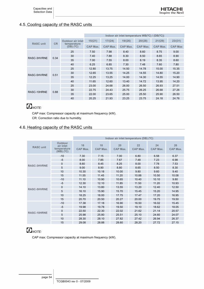
4.5. Cooling capacity of the RASC units
Indoor air inlet temperature WB(ºC) / (DB(ºC))
RASC unit CROutdoor air inlet
temperature (DB) (ºC)
15/(21) 17/(24) 19/(26) 20/(28) 21/(29) 23/(31)
CAP Max. CAP Max. CAP Max. CAP Max. CAP Max. CAP Max
RASC-3HVRNE 0.34
25 7.50 7.98 8.40 8.60 8.75 9.0030 7.40 7.88 8.30 8.50 8.65 8.9035 7.00 7.55 8.00 8.19 8.35 8.6040 6.25 6.85 7.30 7.48 7.60 7.80
RASC-5HVRNE 0.51
25 12.80 13.75 14.50 14.78 15.00 15.3530 12.65 13.55 14.25 14.55 14.80 15.2035 12.25 13.25 14.00 14.30 14.55 14.9040 11.65 12.60 13.40 14.72 13.95 14.20
RASC-10HRNE 0.88
25 23.00 24.68 26.00 26.50 26.93 27.5130 22.75 24.43 25.75 26.25 26.68 27.2635 22.00 23.65 25.00 25.50 25.90 26.5040 20.25 21.93 23.25 23.75 24.18 24.76
NOTE:
CAP max: Compressor capacity at maximum frequency (kW).CR: Correction ratio due to humidity.
4.6. Heating capacity of the RASC units
Indoor air inlet temperature (DB) (ºC)
RASC unitOutdoor air inlet
temperature (WB) (ºC)
16CAP Max.
18CAP Max.
20CAP Max.
22CAP Max.
24CAP Max.
26CAP Max.
RASC-3HVRNE
-10 7.30 7.15 7.00 6.80 6.58 6.37-5 8.00 7.85 7.67 7.48 7.23 6.980 8.60 8.45 8.25 8.00 7.78 7.535 9.00 8.90 8.80 8.65 8.50 8.3010 10.30 10.18 10.00 9.80 9.60 9.4015 11.55 11.45 11.20 10.88 10.50 10.08
RASC-5HVRNE
-10 11.10 10.90 10.65 10.40 10.10 9.80-5 12.30 12.10 11.85 11.50 11.20 10.930 14.10 13.80 13.55 13.20 12.40 12.505 16.10 15.90 15.70 15.45 15.20 14.9510 18.25 18.00 17.75 17.47 17.20 16.9515 20.70 20.50 20.27 20.00 19.75 19.50
RASC-10HRNE
-10 17.38 17.18 16.90 16.50 16.02 15.45-5 19.98 19.78 19.50 19.10 18.62 18.050 22.50 22.30 22.02 21.62 21.14 20.575 25.98 25.80 25.51 25.10 24.60 24.0710 28.30 28.10 27.82 27.42 26.94 26.3715 29.08 28.88 28.60 28.20 27.72 27.15
NOTE:
CAP max: Compressor capacity at maximum frequency (kW).

TCGB0043 rev 0 - 07/2009page 55
Capacities and Selection Data
4
4.7. Correction factors
4.7.1. Piping length correction factor
The correction factor is based on the equivalent piping length in meters (EL) and the height between RASC and indoor units in meters (H). H:
Height between indoor unit and RASC unit (m).
+H: Position of RASC unit is −higher than position of indoor unit (m).-H: Position of RASC unit is −lower than position of indoor unit (m).
L: Actual one-way piping length between indoor unit and RASC unit (m).
EL: Equivalent one-way piping length between indoor unit and RASC unit (m).
+H
-H
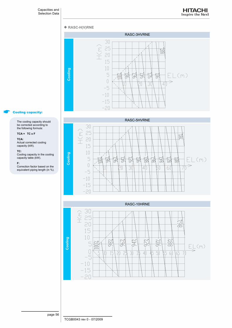
TCGB0043 rev 0 - 07/2009page 56
Capacities and Selection Data
RASC-H(V)RNE ¡
RASC-3HVRNE
Coo
ling
RASC-5HVRNE
Coo
ling
RASC-10HRNE
Coo
ling
Cooling capacity:
The cooling capacity should be corrected according to the following formula:
TCA = TC x F
TCA: Actual corrected cooling capacity (kW).
TC: Cooling capacity in the cooling capacity table (kW).
F: Correction factor based on the equivalent piping length (in %).
Heating capacity
The heating capacity should be corrected according to the following formula:
THA = TH x F
THA: Actual corrected heating capacity (kW)
TH: Heating capacity from heating capacity table (kW).
F: Correction factor based on the equivalent piping length (in %).

TCGB0043 rev 0 - 07/2009page 57
Capacities and Selection Data
4
RASC-H(V)RNE ¡
RASC-3HVRNE
Hea
ting
RASC-5HVRNE
Hea
ting
RASC-10HRNE
Hea
ting
Heating capacity
The heating capacity should be corrected according to the following formula:
THA = TH x F
THA: Actual corrected heating capacity (kW)
TH: Heating capacity from heating capacity table (kW).
F: Correction factor based on the equivalent piping length (in %).
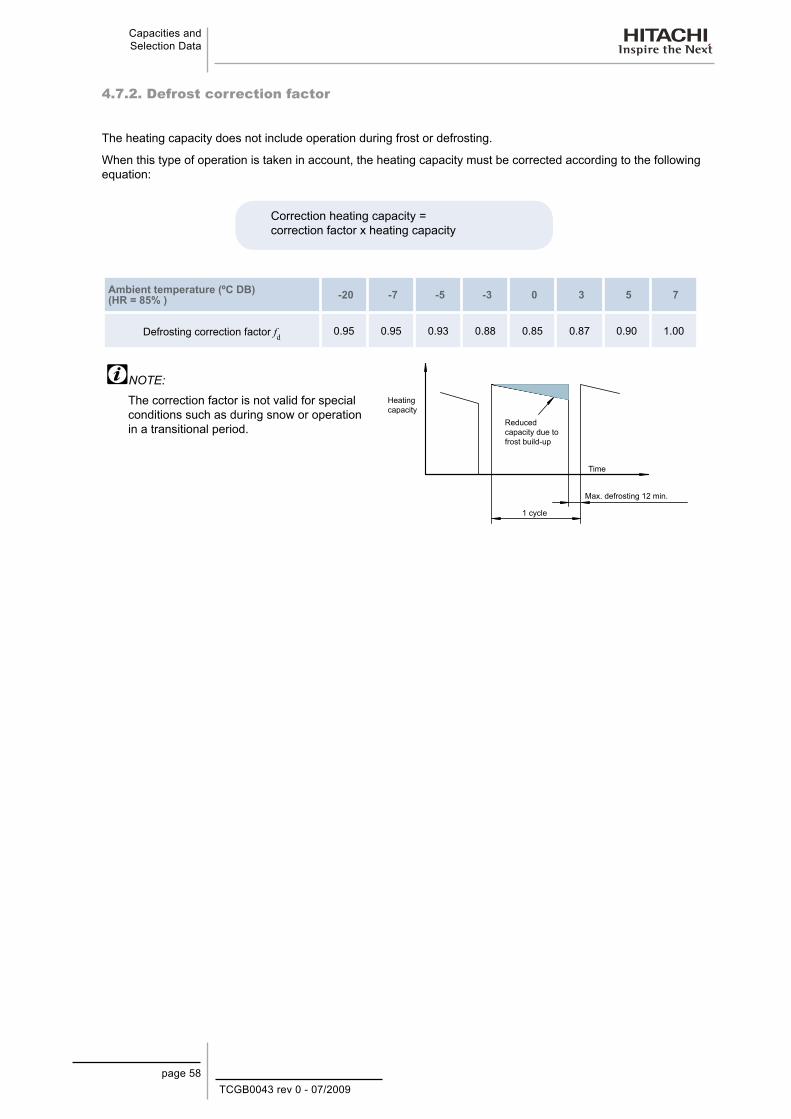
TCGB0043 rev 0 - 07/2009page 58
Capacities and Selection Data
4.7.2. Defrost correction factor
The heating capacity does not include operation during frost or defrosting.
When this type of operation is taken in account, the heating capacity must be corrected according to the following equation:
Correction heating capacity = correction factor x heating capacity
Ambient temperature (ºC DB) (HR = 85% ) -20 -7 -5 -3 0 3 5 7
Defrosting correction factor fd 0.95 0.95 0.93 0.88 0.85 0.87 0.90 1.00
NOTE:
The correction factor is not valid for special conditions such as during snow or operation in a transitional period.
Heating capacity
Reduced capacity due to frost build-up
Time
Max. defrosting 12 min.
1 cycle

TCGB0043 rev 0 - 07/2009page 59
Capacities and Selection Data
4
4.8. Sensible heat factor (SHF)
The sensible heat factor of indoor units at each fan speed (Hi, Me, Lo) based on the JIS Standard B8616, is given below:
Indoor unit modelSHF
Hi Med LowRCI-1.5FSN2E 0.77 0.75 0.73RCI-2.0FSN2E 0.78 0.76 0.75RCI-2.5FSN2E 0.73 0.71 0.69RCI-3.0FSN2E 0.79 0.76 0.72RCI-4.0FSN2E 0.78 0.75 0.72RCI-5.0FSN2E 0.74 0.70 0.68RCI-6.0FSN2E 0.73 0.69 0.68RCIM-1.5FSN2 0.74 0.71 0.70RCIM-2.0FSN2 0.71 0.68 0.67RCD-1.5FSN2 0.73 0.69 0.66RCD-2.0FSN2 0.75 0.67 0.65RCD-2.5FSN2 0.74 0.67 0.65RCD-3.0FSN2 0.74 0.67 0.65RCD-4.0FSN2 0.73 0.67 0.65RCD-5.0FSN2 0.69 0.67 0.65RPC-2.0FSN2E 0.72 0.70 0.67RPC-2.5FSN2E 0.72 0.70 0.67RPC-3.0FSN2E 0.72 0.70 0.67RPC-4.0FSN2E 0.72 0.70 0.67RPC-5.0FSN2E 0.72 0.70 0.67RPC-6.0FSN2E 0.72 0.70 0.67RPI-1.5FSN2E 0.73 0.69 0.65RPI-2.0FSN2E 0.76 0.75 0.74RPI-2.5FSN2E 0.76 0.74 0.72RPI-3.0FSN2E 0.75 0.71 0.67RPI-4.0FSN2E 0.73 0.71 0.65RPI-5.0FSN2E 0.72 0.68 0.64RPI-6.0FSN2E 0.72 0.69 0.67RPI-8.0FSN2E 0.77 0.77 0.70RPI-10.0FSN2E 0.79 0.79 0.72RPIM-1.5FSN2E 0.71 0.68 0.64RPK-1.5FSN2M 0.73 0.72 0.70RPK-2.0FSN2M 0.72 0.72 0.70RPK-2.5FSN2M 0.72 0.72 0.70RPK-3.0FSN2M 0.71 0.72 0.70RPK-4.0FSN2M 0.71 0.72 0.70RPF-1.5FSN2E 0.73 0.69 0.65RPF-2.0FSN2E 0.73 0.69 0.65RPF-2.5FSN2E 0.73 0.69 0.65RPFI-1.5FSN2E 0.73 0.69 0.65RPFI-2.0FSN2E 0.73 0.69 0.65RPFI-2.5FSN2E 0.73 0.69 0.65

TCGB0043 rev 0 - 07/2009page 60
Capacities and Selection Data
4.9. Fan performance
RASC unit could be installed using ducts at inlet and outlet air. Refer to fan performance curve, in order to ensure that the air volume is within working range. It’s assumed that unit will be installed using supply and return air ducts. Find below fan performance curve to decide which ducts are suitable
RASC-3HVRNE RASC-5HVRNE RASC-10HRNE
Ext
erna
l Sta
tic P
ress
ure
(mm
Aq)
Ext
erna
l Sta
tic P
ress
ure
(mm
Aq)
Ext
erna
l Sta
tic P
ress
ure
(mm
Aq)
Air flow (m³/min)“” Nominal Point
Air flow (m³/min)“” Nominal Point
Air flow (m³/min)“” Nominal Point
NOTE:When design a duct, check to ensure that the Air volume is within working range as indicate “Fan Performance −Curve”.If the Air volume is set outside working range, water-carry-over (drop in the ceiling or into the room), noise −increases, fan motor damaged (high temperature), insufficient Cooling/Heating capacity, phenomena can occur. Therefore design ducts and select the correct fan speed in order to keep the unit running in the accepted working −range selected.

TCGB0043 rev 0 - 07/2009page 61
Capacities and Selection Data
4
4.10. Sound dataRASC–H(V)RNE units ¡
Model: RASC-3HVRNE Power source: 230V 50Hz Model: RASC-5HVRNE Power source: 230V 50Hz
Oct
ave
soun
d pr
essu
re (d
B (C
))
Measurement point: 1.5 meters beneath the unit(With duct)
Acoustic criteria curve
Oct
ave
soun
d pr
essu
re (d
B (C
))
Measurement point: 1.5 meters beneath the unit(With duct)
Acoustic criteria curveCool/Heat: 46/46 dB(A)
Approximate continuous noise detection threshold
Cool/Heat: 55/56 dB(A)
Approximate continuous noise detection threshold
Frequency (Hz) Frequency (Hz)
Model: RASC-10HRNE Power source: 400V 50Hz
Oct
ave
soun
d pr
essu
re (d
B (C
))
Measurement point: 1.5 meters beneath the unit(With duct)
Acoustic criteria curveNominal: 68 dB(A)
Approximate continuous noise detection threshold
Frequency (Hz)

TCGB0043 rev 0 - 07/2009page 63
Working Range
5. W o r k i n g R a n g e
5
This chapter shows the working range of the Hitachi RASC-H(V)RNE Series.
Contents
5. Working Range ........................................................................................................635.1. Power Supply ....................................................................................................................................... 64
5.2. Temperature Range .............................................................................................................................. 64

TCGB0043 rev 0 - 07/2009page 64
Working Range
5.1. Power Supply
Operating voltage 90% to 110% of the nominal voltage
Voltage imbalance Within a 3% deviation from each voltage at the main terminal of the outdoor unit
Starting voltage Higher than 85% of the nominal voltage
Following Council Directive 89/336/EEC and amendments 92/31/EEC and 93/68/EEC, relating to electromagnetic compatibility, the following table indicates maximum permissible system impedance Zmax at the interface point of the user’s power supply, in accordance with EN61000-3-11.
MODEL Zmax (Ω)
RASC-3HVRNE 0.26RASC-5HVRNE 0.19RASC-10HVRNE 0.20
5.2. Temperature Range
The temperature range is indicated in the following table:
Cooling Operation Heating Operation
Indoor temperature
Minimum 21°C DB/15°C WB 15°C DBMaximum 32°C DB/23°C WB 27°C DB
Outdoor temperature
Minimum -5°C DB -15°C WB Maximum 43°C DB 15.5°C WB
Temperature range diagram:
Cooling Operation Heating Operation
NOTE:DB: dry bulb; WB: wet bulb
Operation control range
-5
43
15 23
Out
door
air
tem
pera
ture
(°C
DB
)
Indoor air inlet temperature (°C WB) 27
-15
15.5
Out
door
air
tem
pera
ture
(°C
WB
)
Indoor air inlet temperature (°C DB)
TCGB0043 rev 0 - 07/2009page 65
Refrigerant Cycle
6
6. R e f r i g e r a n t C y c l e
This chapter displays the refrigerant cycle diagrams for the units of the Hitachi RASC-H(V)RNE series.
Contents
6. Refrigerant Cycle .....................................................................................................656.1. Example of single combination ............................................................................................................. 66
6.2. Example of double combination ........................................................................................................... 67
6.4. Example of quadruple combination ...................................................................................................... 68

TCGB0043 rev 0 - 07/2009page 66
Refrigerant Cycle
6.1. Example of single combination
RASC-3HVRNE
Cooling Refrigerant
Flow
Heating Refrigerant
Flow
Installation Refrigerant
Piping LineFlare Nut Connectiion Flange Connection Brazing Connection
Nº Name of Item1 Compressor2 Heat exchanger3 Liquid tank4 Strainer5 Distributor6 Revercing valve7 Capilary tube8 Electronic expansion valve9 Solenoid valve
10 Check joint11 Stop valve for liquid line
Nº Name of Item12 Stop valve for gas line13 High pressure switch for protection14 Pressure switch for control15 Ambient thermistor16 Condenser pipe thermistor17 Discharge gas thermistor18 Indoor exchanger19 Strainer20 Electronic expansion valve21 Distributor

TCGB0043 rev 0 - 07/2009page 67
Refrigerant Cycle
6
6.2. Example of double combination
RASC-5HVRNE
Cooling Refrigerant
Flow
Heating Refrigerant
Flow
Installation Refrigerant
Piping LineFlare Nut Connectiion Flange Connection Brazing Connection
Nº Name of Item1 Compressor2 Heat exchanger3 Liquid tank4 Strainer5 Distributor6 Revercing valve7 Capilary tube8 Electronic expansion valve9 Solenoid valve
10 Check joint11 Stop valve for liquid line12 Stop valve for gas line
Nº Name of Item13 High pressure switch for protection14 Pressure switch for control15 Ambient thermistor16 Condenser pipe thermistor17 Discharge gas thermistor18 Multikit (Liquid line)19 Multikit (Gas line)20 Indoor exchanger21 Strainer22 Electronic expansion valve23 Distributor
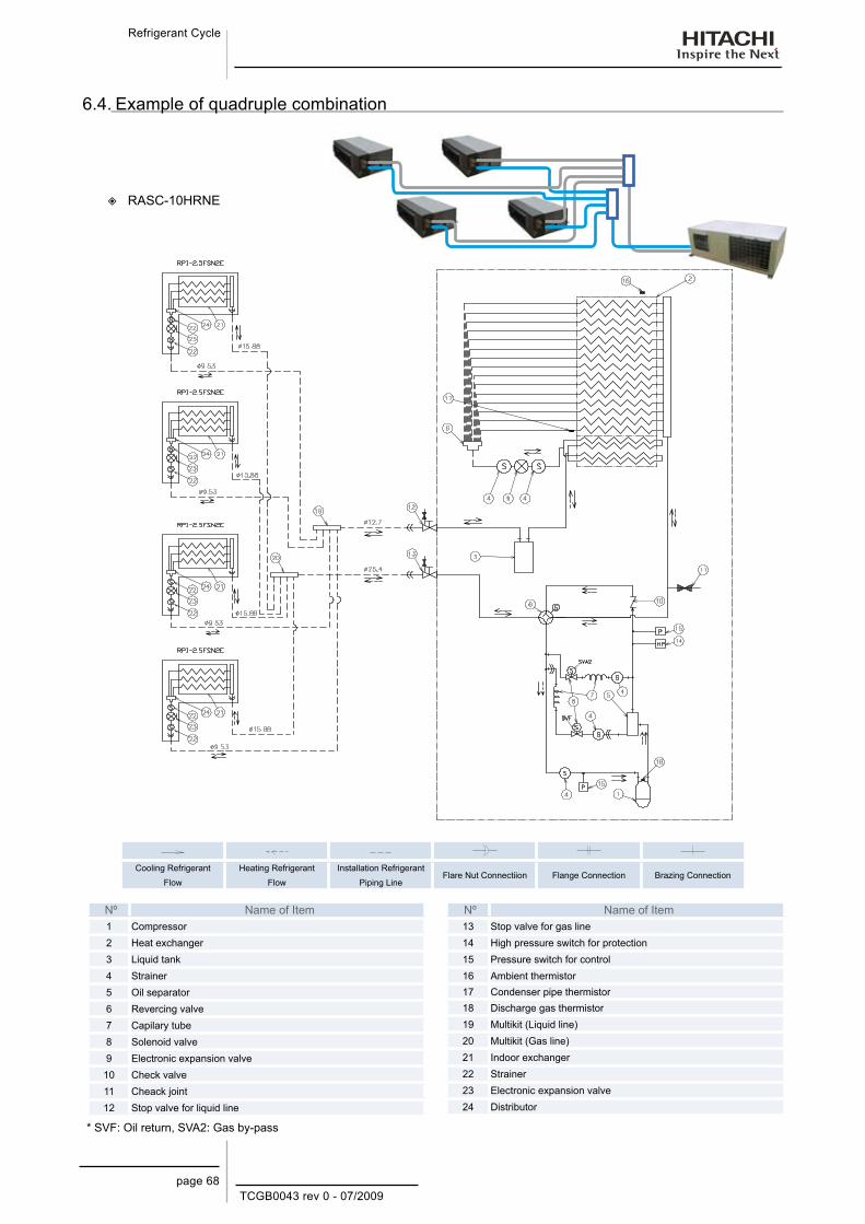
TCGB0043 rev 0 - 07/2009page 68
Refrigerant Cycle
6.4. Example of quadruple combination
RASC-10HRNE
Cooling Refrigerant
Flow
Heating Refrigerant
Flow
Installation Refrigerant
Piping LineFlare Nut Connectiion Flange Connection Brazing Connection
Nº Name of Item1 Compressor2 Heat exchanger3 Liquid tank4 Strainer5 Oil separator6 Revercing valve7 Capilary tube8 Solenoid valve9 Electronic expansion valve
10 Check valve11 Cheack joint12 Stop valve for liquid line
Nº Name of Item13 Stop valve for gas line14 High pressure switch for protection15 Pressure switch for control16 Ambient thermistor17 Condenser pipe thermistor18 Discharge gas thermistor19 Multikit (Liquid line)20 Multikit (Gas line)21 Indoor exchanger22 Strainer23 Electronic expansion valve24 Distributor
* SVF: Oil return, SVA2: Gas by-pass

TCGB0043 rev 0 - 07/2009page 69
Piping and Refrigerant charge
7. P i p i n g a n d r e f r i g e r a n t c h a r g e
7
This chapter describes how to connect the refrigerant piping and change the amount of refrigerant in the system for the Hitachi RASC series.
Contents
7. Piping and refrigerant charge ..............................................................697.1. Refrigerant piping .........................................................................................................70
7.1.1. Refrigerant piping range .......................................................................................................707.1.2. Refrigerant piping length ......................................................................................................707.1.3. Refrigerant piping selection .................................................................................................71
7.2. Multi-kits and distributors ..............................................................................................72
7.2.1. Size data ..............................................................................................................................727.2.2. Twin and quadruple system installation ...............................................................................737.2.3. Piping materials ....................................................................................................................74
7.3. Amount refrigerant charge ............................................................................................76
7.3.1. Additional refrigerant charge calculation (R410A) ................................................................767.3.2. Simple example of refrigerant charge quantity calculation ..................................................78
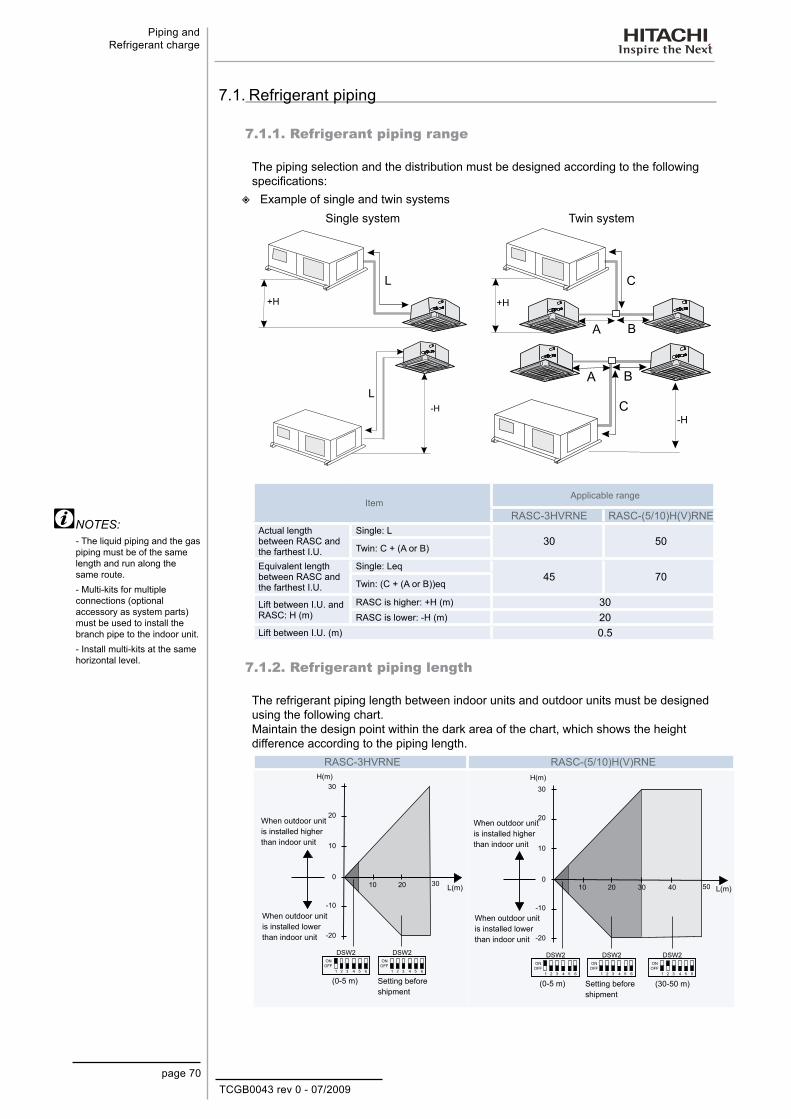
TCGB0043 rev 0 - 07/2009page 70
Piping and Refrigerant charge
7.1. Refrigerant piping
7.1.1. Refrigerant piping range
The piping selection and the distribution must be designed according to the following specifications:
Example of single and twin systems
Single system Twin system
+H +H
-H-H
ItemApplicable range
RASC-3HVRNE RASC-(5/10)H(V)RNEActual length between RASC and the farthest I.U.
Single: L30 50
Twin: C + (A or B)
Equivalent length between RASC and the farthest I.U.
Single: Leq45 70
Twin: (C + (A or B))eq
Lift between I.U. and RASC: H (m)
RASC is higher: +H (m) 30RASC is lower: -H (m) 20
Lift between I.U. (m) 0.5
7.1.2. Refrigerant piping length
The refrigerant piping length between indoor units and outdoor units must be designed using the following chart.Maintain the design point within the dark area of the chart, which shows the height difference according to the piping length.
RASC-3HVRNE RASC-(5/10)H(V)RNE
When outdoor unit is installed higher than indoor unit
When outdoor unit is installed lower than indoor unit
Setting before shipment
(0-5 m)
When outdoor unit is installed higher than indoor unit
When outdoor unit is installed lower than indoor unit
Setting before shipment
(30-50 m)(0-5 m)
NOTES:- The liquid piping and the gas piping must be of the same length and run along the same route.- Multi-kits for multiple connections (optional accessory as system parts) must be used to install the branch pipe to the indoor unit.- Install multi-kits at the same horizontal level.
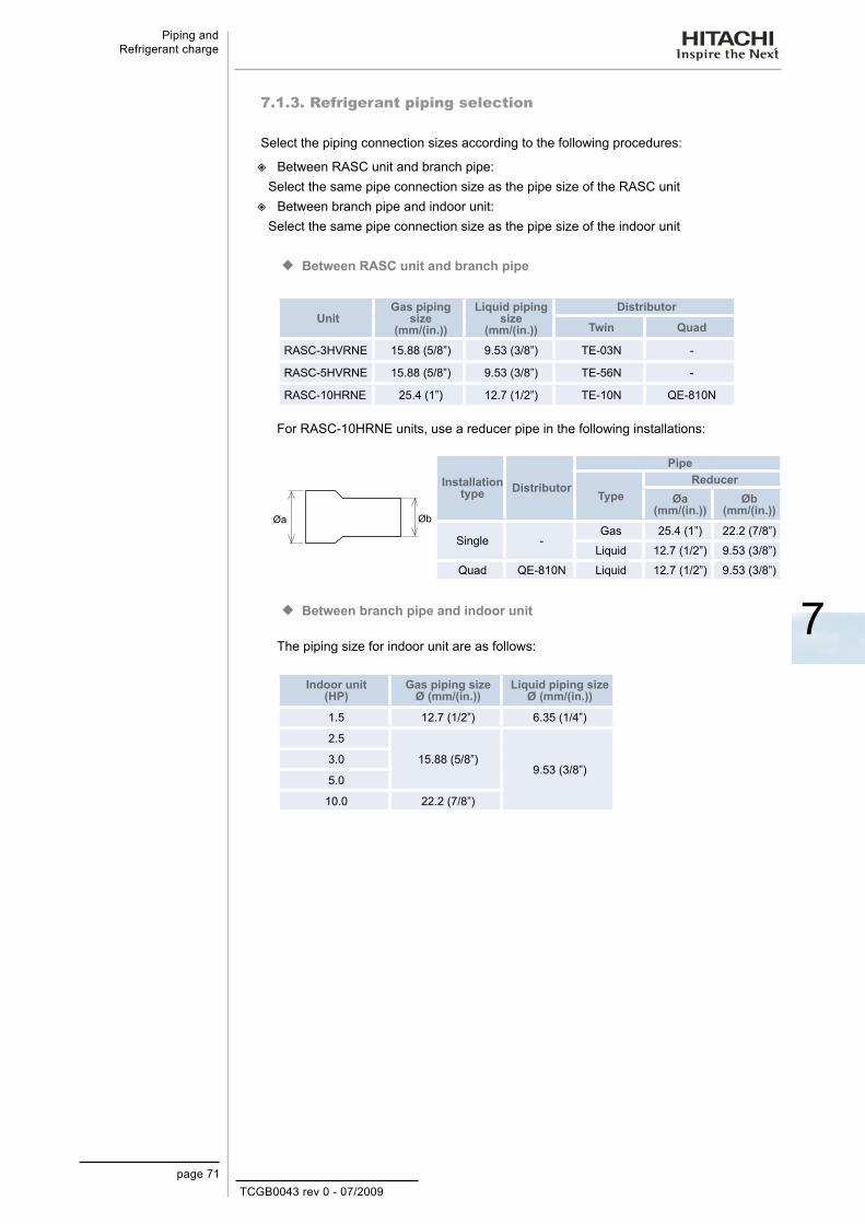
TCGB0043 rev 0 - 07/2009page 71
Piping and Refrigerant charge
7
7.1.3. Refrigerant piping selection
Select the piping connection sizes according to the following procedures:
Between RASC unit and branch pipe:
Select the same pipe connection size as the pipe size of the RASC unitBetween branch pipe and indoor unit:
Select the same pipe connection size as the pipe size of the indoor unit
Between RASC unit and branch pipe ¡
UnitGas piping
size (mm/(in.))
Liquid piping size
(mm/(in.))
Distributor
Twin Quad
RASC-3HVRNE 15.88 (5/8”) 9.53 (3/8”) TE-03N -
RASC-5HVRNE 15.88 (5/8”) 9.53 (3/8”) TE-56N -
RASC-10HRNE 25.4 (1”) 12.7 (1/2”) TE-10N QE-810N
For RASC-10HRNE units, use a reducer pipe in the following installations:
ØbØa
Installation type Distributor
Pipe
TypeReducer
Øa (mm/(in.))
Øb (mm/(in.))
Single -Gas 25.4 (1”) 22.2 (7/8”)
Liquid 12.7 (1/2”) 9.53 (3/8”)
Quad QE-810N Liquid 12.7 (1/2”) 9.53 (3/8”)
Between branch pipe and indoor unit ¡
The piping size for indoor unit are as follows:
Indoor unit (HP)
Gas piping size Ø (mm/(in.))
Liquid piping size Ø (mm/(in.))
1.5 12.7 (1/2”) 6.35 (1/4”)
2.5
15.88 (5/8”)9.53 (3/8”)
3.0
5.0
10.0 22.2 (7/8”)
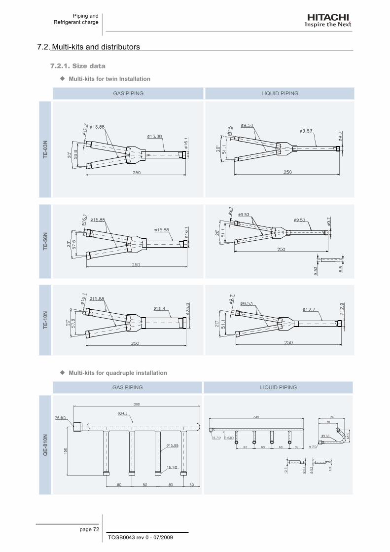
TCGB0043 rev 0 - 07/2009page 72
Piping and Refrigerant charge
7.2. Multi-kits and distributors
7.2.1. Size data
Multi-kits for twin Installation ¡
GAS PIPING LIQUID PIPING
TE-0
3NTE
-56N
TE-1
0N
Multi-kits for quadruple installation ¡
GAS PIPING LIQUID PIPING
QE-
810N
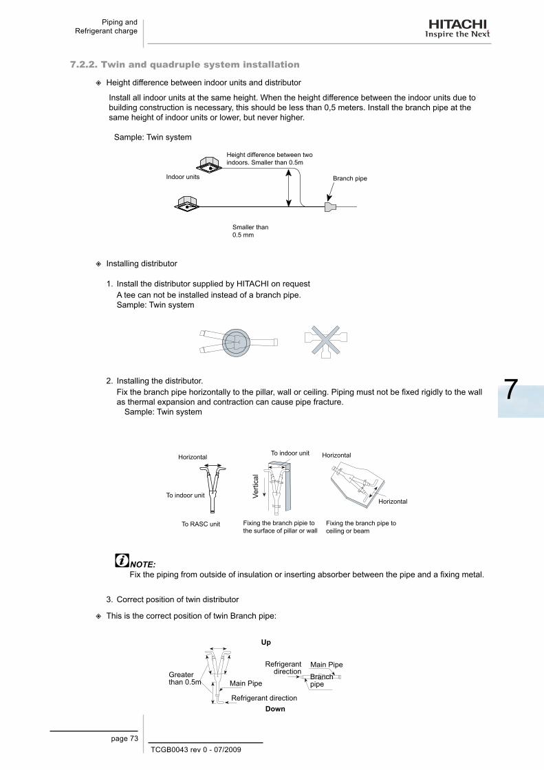
TCGB0043 rev 0 - 07/2009page 73
Piping and Refrigerant charge
7
7.2.2. Twin and quadruple system installation
Height difference between indoor units and distributor
Install all indoor units at the same height. When the height difference between the indoor units due to building construction is necessary, this should be less than 0,5 meters. Install the branch pipe at the same height of indoor units or lower, but never higher.
Sample: Twin system
Indoor units
Smaller than 0.5 mm
Height difference between two indoors. Smaller than 0.5m
Branch pipe
Installing distributor
1. Install the distributor supplied by HITACHI on request A tee can not be installed instead of a branch pipe.Sample: Twin system
2. Installing the distributor. Fix the branch pipe horizontally to the pillar, wall or ceiling. Piping must not be fixed rigidly to the wall as thermal expansion and contraction can cause pipe fracture. Sample: Twin system
Horizontal
To RASC unit
To indoor unit Verti
cal
To indoor unit
Fixing the branch pipie to the surface of pillar or wall
Horizontal
Horizontal
Fixing the branch pipe to ceiling or beam
NOTE:Fix the piping from outside of insulation or inserting absorber between the pipe and a fixing metal.
3. Correct position of twin distributor
This is the correct position of twin Branch pipe:
Up
Down
Greater than 0.5m Main Pipe
Refrigerant direction
Refrigerant direction
Main PipeBranch pipe

TCGB0043 rev 0 - 07/2009page 74
Piping and Refrigerant charge
This is wrong position.
Up
Down
Main PipeRefrigerant
direction
Main Pipe
Branch pipe
Branch pipe Branch
pipe
4. Correct position of Quad Distributor.
Install the header horizontally
Sample: Quad Branch pipe
Gas piping
Liquid piping
7.2.3. Piping materials
1. Prepare locally-supplied copper pipes.
2. Select the correct pipe size and material. Use the table below to select the required piping.
Nominal Diameter Thickness (mm) Copper Type
(mm) (in.)
6.35 1/4 0.80 Roll9.53 3/8 0.80 Roll
12.70 1/2 0.80 Pipe/Roll15.88 5/8 1.00 Roll19.05 3/4 1.00 Pipe/Roll22.23 7/8 1.00 Pipe/Roll25.40 1 1.00 Pipe
3. Select clean copper pipes. Make sure there is no dust and moisture inside. Blow the inside of the pipes through with oxygen-free nitrogen to remove any dust and foreign materials before connecting pipes.
4. After connecting the refrigerant piping, seal the open space between the knockout hole and refrigerant pipes by using insulation material as shown below:
Insulator
Field-supplied refrigeration piping
InsulatorInsulator
NOTE:If copper pipe is used for piping bigger than Ø19.05 flaring work can not be performed. If necessary, use a joint adapter.
CAUTION:Do not use saws. grindstones or other tools which might create copper dust.
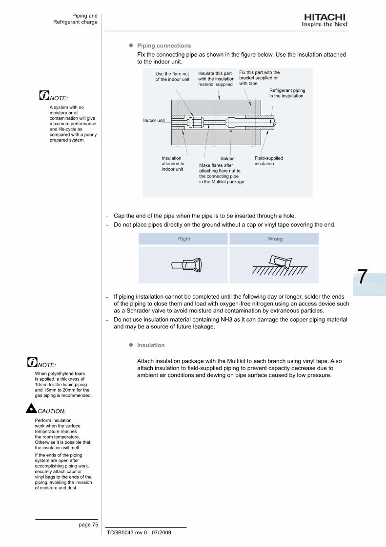
TCGB0043 rev 0 - 07/2009page 75
Piping and Refrigerant charge
7
Piping connections ¡Fix the connecting pipe as shown in the figure below. Use the insulation attached to the indoor unit.
Use the flare nut of the indoor unit
Insulate this part with the insulation material supplied
Fix this part with the bracket supplied or with tape
Refrigerant piping in the installation
Field-supplied insulation
SolderMake flares after attaching flare nut to the connecting pipe in the Multikit package
Insulation attached to indoor unit
Indoor unit
Cap the end of the pipe when the pipe is to be inserted through a hole. −
Do not place pipes directly on the ground without a cap or vinyl tape covering the end. −
Right Wrong
If piping installation cannot be completed until the following day or longer, solder the ends −of the piping to close them and load with oxygen-free nitrogen using an access device such as a Schrader valve to avoid moisture and contamination by extraneous particles. Do not use insulation material containing NH3 as it can damage the copper piping material −and may be a source of future leakage.
Insulation ¡
Attach insulation package with the Multikit to each branch using vinyl tape. Also attach insulation to field-supplied piping to prevent capacity decrease due to ambient air conditions and dewing on pipe surface caused by low pressure.
A system with no moisture or oil contamination will give maximum performance and life-cycle as compared with a poorly prepared system.
NOTE:
NOTE:When polyethylene foam is applied. a thickness of 10mm for the liquid piping and 15mm to 20mm for the gas piping is recommended.
Perform insulation work when the surface temperature reaches the room temperature. Otherwise it is possible that the insulation will melt. If the ends of the piping system are open after accomplishing piping work. securely attach caps or vinyl bags to the ends of the piping. avoiding the invasion of moisture and dust.
CAUTION:

TCGB0043 rev 0 - 07/2009page 76
Piping and Refrigerant charge
7.3. Refrigerant charge amount
7.3.1. Additional refrigerant charge calculation (R410A)
Although refrigerant has been charged into this unit, additional refrigerant charge is required according to piping length.
The additional refrigerant quantity should be determined and charged into the −system according to the following procedure.
Record the additional refrigerant quantity in order to facilitate maintenance and −servicing activities.
Calculating method of additional refrigerant charge (W kg) ¡Calculate the additional refrigerant charge amount according to the following steps:
Additional refrigerant charge calculation for liquid piping (W1 (kg))
Calculate W1 by the following formula:
W1= (AL-l) x p
AL: Piping length (m)l: Charge-less piping length (m)p: Compensation rate (kg/m)* This values are shown below
Single system Twin systemRASC-(3/5/10)H(V)RNE
Indoor unit
AL
RASC-(3/5/10)H(V)RNE
Indoor unit Indoor unit
AL: Piping length (m) AL: A+B+C = Piping length (m)
RASC MODELl
Charge-less length (m)
p Compensating rate
(kg/m)
RASC-3HVRNE 20 0.06RASC-5HVRNE 30 0.06
RASC-10HRNE 30 0.12
Step 1:
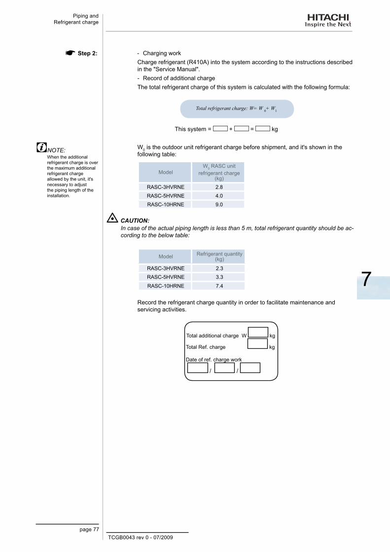
TCGB0043 rev 0 - 07/2009page 77
Piping and Refrigerant charge
7
- Charging workCharge refrigerant (R410A) into the system according to the instructions described in the "Service Manual".- Record of additional chargeThe total refrigerant charge of this system is calculated with the following formula:
Total refrigerant charge: W= W 0+ W1
This system = + = kg
W0 is the outdoor unit refrigerant charge before shipment, and it's shown in the following table:
ModelW0 RASC unit
refrigerant charge (kg)
RASC-3HVRNE 2.8RASC-5HVRNE 4.0RASC-10HRNE 9.0
CAUTION:In case of the actual piping length is less than 5 m, total refrigerant quantity should be ac-cording to the below table:
Model Refrigerant quantity (kg)
RASC-3HVRNE 2.3RASC-5HVRNE 3.3
RASC-10HRNE 7.4
Record the refrigerant charge quantity in order to facilitate maintenance and servicing activities.
Total additional charge W kg
Total Ref. charge kg
Date of ref. charge work
/ /
Step 2:
When the additional refrigerant charge is over the maximum additional refrigerant charge allowed by the unit, it's necessary to adjust the piping length of the installation.
NOTE:
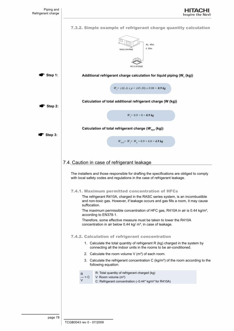
TCGB0043 rev 0 - 07/2009page 78
Piping and Refrigerant charge
7.3.2. Simple example of refrigerant charge quantity calculation
AL: 45m
l: 30mRASC-5HVRNE
RCI-5.0FSN2E
Additional refrigerant charge calculation for liquid piping (W1 (kg))
W1= (AL-l) x p = (45-30) x 0.06 = 0.9 kg
Calculation of total additional refrigerant charge (W (kg))
W1= 0.9 + 0 = 0.9 kg
Calculation of total refrigerant charge (WTOT (kg))
WTOT= W1+ W0 = 0.9 + 4.0 = 4.9 kg
7.4. Caution in case of refrigerant leakage
The installers and those responsible for drafting the specifications are obliged to comply with local safety codes and regulations in the case of refrigerant leakage.
7.4.1. Maximum permitted concentration of HFCsThe refrigerant R410A, charged in the RASC series system, is an incombustible and non-toxic gas. However, if leakage occurs and gas fills a room, it may cause suffocation.The maximum permissible concentration of HFC gas, R410A in air is 0.44 kg/m³, according to EN378-1.Therefore, some effective measure must be taken to lower the R410A concentration in air below 0.44 kg/ m³, in case of leakage.
7.4.2. Calculation of refrigerant concentration1. Calculate the total quantity of refrigerant R (kg) charged in the system by
connecting all the indoor units in the rooms to be air-conditioned.
2. Calculate the room volume V (m³) of each room.
3. Calculate the refrigerant concentration C (kg/m³) of the room according to the following equation:
R — = C V
R: Total quantity of refrigerant charged (kg)V: Room volume (m³)C: Refrigerant concentration (=0.44* kg/m³ for R410A)
Step 3:
Step 2:
Step 1:
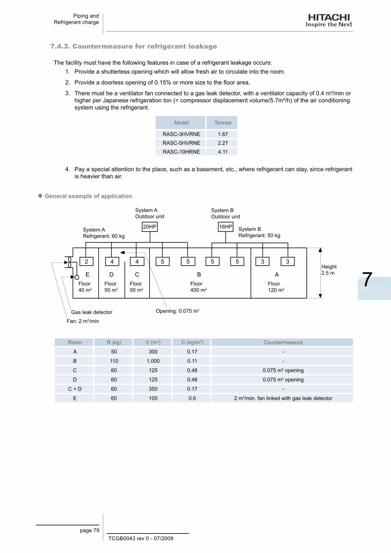
TCGB0043 rev 0 - 07/2009page 79
Piping and Refrigerant charge
7
7.4.3. Countermeasure for refrigerant leakage
The facility must have the following features in case of a refrigerant leakage occurs:1. Provide a shutterless opening which will allow fresh air to circulate into the room.
2. Provide a doorless opening of 0.15% or more size to the floor area.
3. There must be a ventilator fan connected to a gas leak detector, with a ventilator capacity of 0.4 m³/min or higher per Japanese refrigeration ton (= compressor displacement volume/5.7m³/h) of the air conditioning system using the refrigerant.
Model Tonnes
RASC-3HVRNE 1.67
RASC-5HVRNE 2.27
RASC-10HRNE 4.11
4. Pay a special attention to the place, such as a basement, etc., where refrigerant can stay, since refrigerant is heavier than air.
General example of application ¡
Gas leak detector
System A Refrigerant: 60 kg
System B Refrigerant: 50 kg
System B Outdoor unit
System A Outdoor unit
Fan: 2 m3/min
Floor 40 m2
Floor 50 m2
Floor 50 m2
Floor 400 m2
Floor 120 m2
Height 2.5 m
Opening: 0.075 m2
Room R (kg) V (m3) C (kg/m3) Countermeasure
A 50 300 0.17 -
B 110 1,000 0.11 -
C 60 125 0.48 0.075 m2 opening
D 60 125 0.48 0.075 m2 opening
C + D 60 350 0.17 -
E 60 100 0.6 2 m3/min. fan linked with gas leak detector


TCGB0043 rev 0 - 07/2009page 81
Electrical Data
8
8. E l e c t r i c a l D a t a
This chapter describes the electrical requirements for each unit of the Hitachi RASC-H(V)RNE series.
Contents
8. Electrical Data .........................................................................................................818.1. Electrical data for RASC-H(V)RNE ....................................................................................................... 82
8.1.1. RASC-(3/5/10)H(V)RNE .................................................................................................................................. 82

TCGB0043 rev 0 - 07/2009
Electrical Data.
page 82
8.1. Electrical data for RASC-H(V)RNE
8.1.1. RASC-(3/5/10)H(V)RNE
Model
Unit Power Source Applicable Voltage Compressor and Fan Motors
Max. IPT [kW]
Max. Cur. [A]
U [V] PH
f [Hz]
U max. [V]
U min [V] PH
STC [A]
Cooling Operation Heating Operation
IPT [KW]
RNC [A]
IPT [KW]
RNC [A]
RASC-3HVRNE 230 1 50 253 207 1 - 2.47 11.3 2.60 11.9 6.33 28.0RASC-5HVRNE 230 1 50 253 207 1 - 2.65 22.0 4.56 21.6 8.76 37.0RASC-10HRNE 400 3 50 440 360 3 - 8.60 20.1 8.70 20.2 15.07 33.0
U: Power voltage PH: Phase (φ)f: FrequencySTC: Starting currentRNC: Operating current IPT: Total input powerCur: Current
NOTES:1. The compressor data shown in the table above are based
on a combined capacity of 100% of the power supplied, with the following working frequency:
Cool HeatRASC-3HVRNE 46 54RASC-5HVRNE 64 67RASC-10HRNE 74 83
2. The above performance data are based on an equivalent piping length of 7.5m and 0m piping lift
3. This data is based on the same conditions of nominal heating and cooling capacities. The compressor with inverter control has low electrical power consumption at start-up
4. The specifications in these tables are subject to change without notice to allow HITACHI to offer its customers the latest innovations.
TCGB0043 rev 0 - 07/2009
9
Electrical Wiring
page 83
9. E l e c t r i c a l W i r i n g
This chapter describes the electrical wiring connections and how to set the dip switches and the H-Link II System of the Hitachi RASC-H(V)RNE Series.
Contents
9. Electrical Wiring ...................................................................................839.1 General Check..............................................................................................................84
9.2. Setting and Function of DIP Switches for RASC units .................................................85
9.3. Common Wiring ............................................................................................................87
9.3.1. Electrical Wiring between Indoor and RASC units ...............................................................87
9.4. Wiring Size ...................................................................................................................88

TCGB0043 rev 0 - 07/2009
Electrical Wiring
page 84
9.1 General Check
WARNING:
– Turn OFF the main power switch on the indoor and outdoor units before carrying out electrical wiring or regular checks.
– Check to ensure that the indoor fan and the outdoor fan have stopped before electrical wiring work or a periodical check is performed.
– Protect wires, drain pipe, electrical parts, etc. from rats or other small animals. If all these parts are not protected, rats or other small animals may gnaw at them and possibly cause a fire.
– Make sure the wires are not touching the refrigerant pipes, plate edges and electricalparts on the inside of the unit. Otherwise the wires will be damaged and may cause a fire.
– Secure the wires firmly with the clamp to the inside of the indoor unit.
NOTE:
Fix the rubber bushes with adhesive when the outdoor unit ducts are not used.
1. Make sure that the field-supplied electrical components (main power switches, circuit breakers, wires, duct connectors and wire terminals) have been properly selected according to the electrical data in this technical catalog. Make sure that the components comply with the National Electrical Code (NEC).
2. Check to ensure that the power supply voltage is within ± 10% of the rated voltage.
3. Check the capacity of the electrical wiring. If the power source capacity is too low, the system cannot be started due to voltage drop.
4. Check to ensure that the earth wire is connected.5. Main power source switch
Install a multi-pole main switch with a space of 3.5mm or more between each phase.

TCGB0043 rev 0 - 07/2009
9
Electrical Wiring
page 85
9.2. Setting and Function of DIP Switches for RASC unitsNumber and position of DIP switches.
The PCB in the outdoor unit operates with 6 types of DIP switches, 6 cut-off switches and 3 types of push-switches.Position of DIP switches:
DSW1: Test run. −
Factory setting is all OFF
Before shipment
Test Run for cooling Continuous operation during 2 hours is performed
without thermo OFF. The 3 minutes guard for
compressor protection is not effective during the test run
operation.Test Run for heating
Enforced compressor OFF
Compressor operation is OFF during the operation.
DSW2: Pipe length/ Selection of optional functions. −
Before shipment
Piping Length (0~5 m)
Initial expansion valve opening is changed
according to the piping.
Piping Length (More than 30 m)
External input/output selection is set.
Function selection setting Function selection is set by PSW.
External input/output selection
External input/output selection is set by PSW.
The “” mark indicates the position of the DIP switches. The figures show the settings before shipment or after selection.
When using DSW1 the unit starts up or stops 10 to 20 seconds after the switch is operated.
NOTE:
WARNING
Turn off power source before setting DIP switches. If the switches are set without turning off the power source, the settings are invalid.

TCGB0043 rev 0 - 07/2009
Electrical Wiring
page 86
DSW3: Setting capacity. −
RASC-3HVRNE
No. setting is requiredRASC-5HVRNE
RASC-10HRNE
DSW4 and RSW1: Setting number of refrigerant cycles. −
Setting for the tenth digit
Setting for the last digit
DSW5: Setting of end-terminal resistance. − No setting is required. However, to ensure the impedance corresponds, set the DSW5 according to the number of outdoor units of the H-link system.
Setting before shipment End resistance is ON
No setting is required. In case of having 2 or more outdoor units connected to the same H-LINK, set for the second
unit the pin number 1 of DSW5 at OFF.
DSW6: Selection of electrical power supply. − No setting is required.
Setting before shipment400V (RASC-10HRNE)
No setting is required.
Single phase operation230V (RASC-3/5HVRNE)
JP1 cut: Increase in temperature range in Cooling up to -15ºCJP4 cut: Fixing cooling modeJP5 cut: Alternative defrostingJP6 cut: High-pressure control based on R407C piping
NOTE: If JP1 is activated, the
individual control of each indoor unit cannot be used.

TCGB0043 rev 0 - 07/2009
9
Electrical Wiring
page 87
9.3. Common Wiring
9.3.1. Electrical Wiring between Indoor and RASC unitsConnect the electrical wires between the indoor unit and the RASC unit, as shown below.Check to ensure that the terminal for power source wiring (terminals “L1” to “L1” and “N” to “N” of each terminal board: AC230V), and intermediate wires (Operating Line: terminals “1” to “1” and “2” to “2” of each terminal board: DC5V) between the indoor unit and the RASC unit coincide correctly. If not, some component will be damaged.
Follow local codes and regulations when performing electrical wiring. -
Connect the operation wiring to the units in the same refrigerant cycle (The refrigerant piping and the -control wiring should be connected to the same indoor units). If the refrigerant piping ant the control wiring are connected to the units in the different refrigerant cycle, it may cause a abnormal operation.Use twist pair wire (more than 0.75 mm²) for operation wiring between RASC unit and indoor unit, and -operation wiring between indoor units (H-Link connection). It can be also used shielded pair wiring. Shield shall be connected to earth only in one cable side.Use shielded wires for intermediate wiring to protect the units from noise obstacle at length of less than -300 m and size complied with local code.Do not use more than 3 cores for operation wiring (H-Link). Core sizes must be selected according to -the national regulations.Open a hole near the connection hole of power source wiring when multiple RASC units are connected -from one power source line.The recommended breaker sizes are shown in Table of electrical data and recommended Wiring, -Breaker Size/1 O.U.In the case that a conduit tube for field-wiring is not used, fix rubber bushes with adhesive on the panel. -
All the field wiring and equipment must comply with local and international codes. -
CAUTION:All the field wiring and electrical components must comply with local codes.
ATTENTION:Pay attention to the connection of the operating line. Incorrect connection may cause the failure of PCB.
RASC-3/5HVRNE ¡
Outdoor unit of system no. 0
Outdoor unit of system no. 0
Operating line (twisted shielded pair cable or shielded pair cable)
DC5V (non-pole transmission, H-LINK system)
Remote control switch
In RASC-3HVRNE: Max. 2 indoor units per refrigerant cycle
In RASC-5HVRNE: Max. 3 indoor units per refrigerant cycle
Operating line (twisted shielded pair cable or shielded pair cable)
DC5V (non-pole transmission, H-Link system).
Remote control switch
Indoor unit Indoor unit Indoor unit Indoor unit
Terminal boardCircuit breakerEarth leakage breakerField wiringField-suppliedOptional accessory
Power source from the outdoor unit to the indoor unit
Independent power source of outdoor unit and indoor unit
In RASC-3HVRNE: Max. 2 indoor units per refrigerant cycle
In RASC-5HVRNE: Max. 3 indoor units per refrigerant cycle
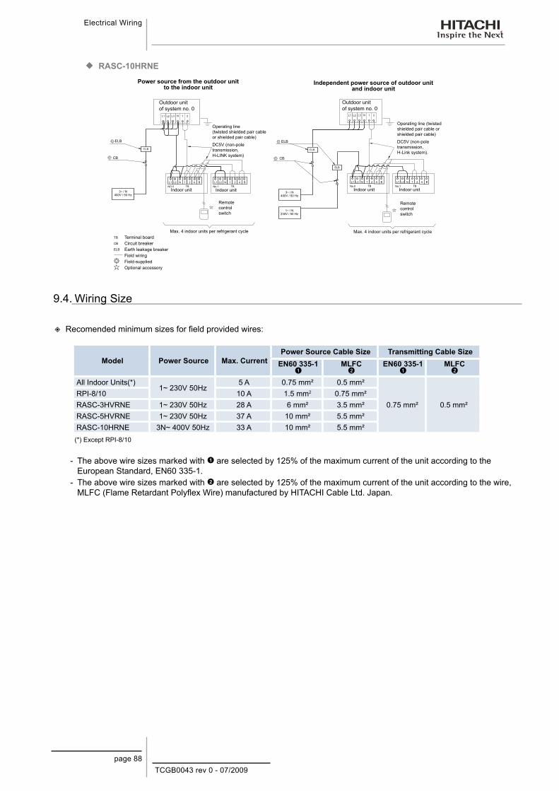
TCGB0043 rev 0 - 07/2009
Electrical Wiring
page 88
RASC-10HRNE ¡
3 N 3 N
Outdoor unit of system no. 0
Outdoor unit of system no. 0
Operating line (twisted shielded pair cable or shielded pair cable)
DC5V (non-pole transmission, H-LINK system)
Remote control switch
Max. 4 indoor units per refrigerant cycle
Operating line (twisted shielded pair cable or shielded pair cable)
DC5V (non-pole transmission, H-Link system).
Remote control switch
Indoor unit Indoor unit Indoor unit Indoor unit
Terminal boardCircuit breakerEarth leakage breakerField wiringField-suppliedOptional accessory
Power source from the outdoor unit to the indoor unit
Independent power source of outdoor unit and indoor unit
Max. 4 indoor units per refrigerant cycle
9.4. Wiring Size
Recomended minimum sizes for field provided wires:
Model Power Source Max. CurrentPower Source Cable Size Transmitting Cable Size
EN60 335-1
MLFC
EN60 335-1
MLFC
All Indoor Units(*)1~ 230V 50Hz
5 A 0.75 mm² 0.5 mm²
0.75 mm² 0.5 mm²RPI-8/10 10 A 1.5 mm2 0.75 mm²RASC-3HVRNE 1~ 230V 50Hz 28 A 6 mm² 3.5 mm²RASC-5HVRNE 1~ 230V 50Hz 37 A 10 mm² 5.5 mm²RASC-10HRNE 3N~ 400V 50Hz 33 A 10 mm² 5.5 mm²
(*) Except RPI-8/10
The above wire sizes marked with - are selected by 125% of the maximum current of the unit according to the European Standard, EN60 335-1.The above wire sizes marked with - are selected by 125% of the maximum current of the unit according to the wire, MLFC (Flame Retardant Polyflex Wire) manufactured by HITACHI Cable Ltd. Japan.
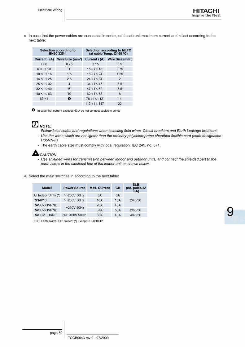
TCGB0043 rev 0 - 07/2009
9
Electrical Wiring
page 89
In case that the power cables are connected in series, add each unit maximum current and select according to the
next table:
Selection according to EN60 335-1
Selection according to MLFC (at cable Temp. Of 60 ºC)
Current i (A) Wire Size (mm²) Current i (A) Wire Size (mm²)I ≤ 6 0.75 I ≤ 15 0.5
6 < i ≤ 10 1 15 < i ≤ 18 0.7510 < i ≤ 16 1.5 18 < i ≤ 24 1.2516 < i ≤ 25 2.5 24 < i ≤ 34 225 < i ≤ 32 4 34 < i ≤ 47 3.532 < i ≤ 40 6 47 < i ≤ 62 5.540 < i ≤ 63 10 62 < i ≤ 78 8
63 < i 78 < i ≤ 112 14112 < i ≤ 147 22
In case that current exceeds 63 A do not connect cables in series
NOTE:Follow local codes and regulations when selecting field wires, Circuit breakers and Earth Leakage breakers -Use the wires which are not lighter than the ordinary polychloroprene sheathed flexible cord (code designation -H05RN-F)The earth cable size must comply with local regulation: IEC 245, no. 571. -
CAUTIONUse shielded wires for transmission between indoor and outdoor units, and connect the shielded part to the -earth screw in the electrical box of the indoor unit as shown below.
Select the main switches in according to the next table:
Model Power Source Max. Current CBELB
(no. poles/A/mA)
All Indoor Units (*) 1~230V 50Hz 5A 6A2/40/30RPI-8/10 1~230V 50Hz 10A 10A
RASC-3HVRNE1~230V 50Hz
28A 40ARASC-5HVRNE 37A 50A 2/63/30RASC-10HRNE 3N~ 400V 50Hz 33A 40A 4/40/30
ELB: Earth switch; CB: Switch; (*) Except RPI-8/10HP

TCGB0043 rev 0 - 07/2009page 91
Optional Functions Available
10
10. O p t i o n a l F u n c t i o n s A v a i l a b l e
This chapter gives a brief explanation of the optional functions available for the new HITACHI RASC-H(V)RNE series.
Contents
10. Optional Functions Available ...................................................................................9110.1. Optional functions available for outdoor units....................................................................................... 92
10.2. Optional functions available from remote controllers............................................................................ 93

TCGB0043 rev 0 - 07/2009
Optional Functions Available
page 92
Available
Not available
10.1. Optional functions available for outdoor units
Optional Functions
Optional Function Explanation
Setting for the energy saving request function.
This function regulates the outdoor unit consumption to 50%, 70% or 100%. If the required power is above the set value, the capacity of the indoor unit will be reduced proportionally to the power consumption of the outdoor unit. It can even come to a thermostatic stop if necessary. This function can be configured using an external or internal signal, depending on the needs of the installation.Configuration by external signal is very useful for setting up groups of outdoor units.The internal signal is useful for setting up a single outdoor unit.
Thermo stoporder.
When this function is activated the compressor is stopped and the indoor units are on thermo OFF.
Low speed defrost adjustment.
When this function is activated the indoor fan speed at defrost mode changes to slow instead of stopping the fan.
Low noise setting This function decreases the sound levels of the outdoor units by reducing the maximum working frequency of the compressor (Cooling/Heating).
Night mode (low noise) operation
This function reduces the sound level of the outdoor units by decreasing the maximum working frequency of the compressor and the fan airflow according to the outside temperature (only for cooling mode).
Change of defrost operation conditions
This function changes the defrosting operation conditions. It is particularly useful for cold areas.
Frequency setting Configuration not available
Protection against cold air discharge (1)
When the air discharge temperature of the indoor unit is less than or equal to 10ºC in cooling mode, the fans stop and the frequency of the outdoor unit is reduced, thereby preventing any discomfort to the occupants of the room.
Protection against cold air discharge (2)
When the discharge temperature of the air in the indoor unit is less than or equal to 10ºC in cooling mode, the compressor stops and alarm no. 24 appears.
Wave function settingThis function controls the outdoor unit consumption in the following way:It allows a consumption of 100% for 20 minutes. The following 10 minutes it goes down to 70% and the alternates between 100% and 70%.
Indoor unit energy-saving temperature setting
This function reduces the power consumption of the indoor unit according to the temperature.
Piping for the R407C If you use conventional R407C piping instead of the R410A, the piping pressure will increase. This function is activated in order to avoid this pressure increase.
Alternation of the defrost mode activation
This function is useful in an installation consisting of various outdoor units placed in the same H-LINK. The defrost mode is activated alternately in each outdoor unit.
New temperature margin in cooling mode.
This function changes the minimum temperature value of the operating range in cooling mode from -5ºC to -15ºC (DB). (only for RASC-10HRNE) units
Setting the cooling mode This function sets the cooling mode: the indoor unit will only start when the system is on COOL or DRY.
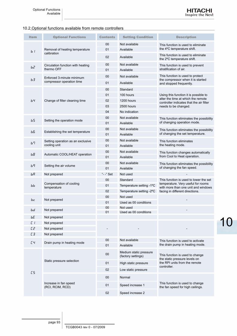
TCGB0043 rev 0 - 07/2009page 93
Optional Functions Available
10
10.2. Optional functions available from remote controllers
Item Optional Functions Contents Setting Condition Description
Removal of heating temperature calibration
00 Not available This function is used to eliminate the 4ºC temperature shift.01 Available
02 Available This function is used to eliminate the 2ºC temperature shift.
Circulation function with heating thermo OFF
00 Not available This function is used to prevent stratification of air. 01 Available
Enforced 3-minute minimum compressor operation time
00 Not available This function is used to protect the compressor when it is started and stopped frequently.01 Available
Change of filter cleaning time
00 Standard
Using this function it is possible to alter the time at which the remote controller indicates that the air filter needs to be changed.
01 100 hours
02 1200 hours
03 2500 hours
04 No indication
Setting the operation mode00 Not available This function eliminates the possibility
of changing operation mode.01 Available
Establishing the set temperature00 Not available This function eliminates the possibility
of changing the set temperature.01 Available
Setting operation as an exclusive cooling unit
00 Not available This function eliminates the heating mode.01 Available
Automatic COOL/HEAT operation00 Not available This function changes automatically
from Cool to Heat operation.01 Available
Setting the air volume00 Not available This function eliminates the possibility
of changing the fan speed.01 Available
A Not prepared “- -” Set Not used -
Compensation of cooling temperature
00 Standard This function is used to lower the set temperature. Very useful for rooms with more than one unit and windows facing in different directions.
01 Temperature setting -1ºC
02 Temperature setting -2ºC
c Not prepared00 Not used
-01 Used as 00 conditions
d Not prepared00 Not used
-01 Used as 00 conditions
e Not prepared
Not prepared
- - - Not prepared
Not prepared
Drain pump in heating mode00 Not available This function is used to activate
the drain pump in heating mode.01 Available
Static pressure selection
00 Medium static pressure (factory settings) This function is used to change
the static pressure levels on the RPI units from the remote controller.
01 High static pressure
02 Low static pressure
Increase in fan speed (RCI, RCIM, RCD)
00 Normal
This function is used to change the fan speed for high ceilings.01 Speed increase 1
02 Speed increase 2
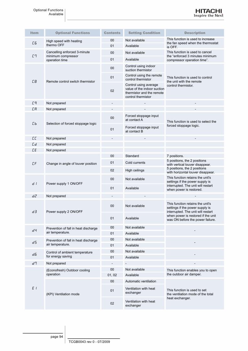
TCGB0043 rev 0 - 07/2009
Optional Functions Available
page 94
Item Optional Functions Contents Setting Condition Description
High speed with heating thermo OFF
00 Not available This function is used to increase the fan speed when the thermostat is OFF.01 Available
Cancelling enforced 3-minute minimum compressor operation time
00 Not available This function is used to cancel the “enforced 3 minutes minimum compressor operation time”.01 Available
Remote control switch thermistor
00 Control using indoor suction thermistor
This function is used to control the unit with the remote control thermistor.
01 Control using the remote control thermistor
02
Control using average value of the indoor suction thermistor and the remote control thermistor
Not prepared - - -
A Not prepared - - -
Selection of forced stoppage logic
00 Forced stoppage input at contact A This function is used to select the
forced stoppage logic.01 Forced stoppage input
at contact B
Not prepared - - -
d Not prepared
E Not prepared
F Change in angle of louver position
00 Standard 7 positions.
01 Cold currents 5 positions, the 2 positions with vertical louver disappear.
02 High ceilings 5 positions, the 2 positions with horizontal louver disappear.
d Power supply 1 ON/OFF00 Not available This function retains the unit's
settings if the power supply is interrupted. The unit will restart when power is restored.01 Available
d Not prepared - - -
d Power supply 2 ON/OFF
00 Not available This function retains the unit's settings if the power supply is interrupted. The unit will restart when power is restored if the unit was ON before the power failure.01 Available
dPrevention of fall in heat discharge air temperature.
00 Not available-
01 Available
dPrevention of fall in heat discharge air temperature.
00 Not available-
01 Available
dControl of ambient temperature for energy saving
00 Not available-
01 Available
d Not prepared - - -
E
(Econofresh) Outdoor cooling operation
00 Not available This function enables you to open the outdoor air damper.01, 02 Available
(KPI) Ventilation mode
00 Automatic ventilation
This function is used to set the ventilation mode of the total heat exchanger.
01 Ventilation with heat exchanger
02 Ventilation with heat exchanger
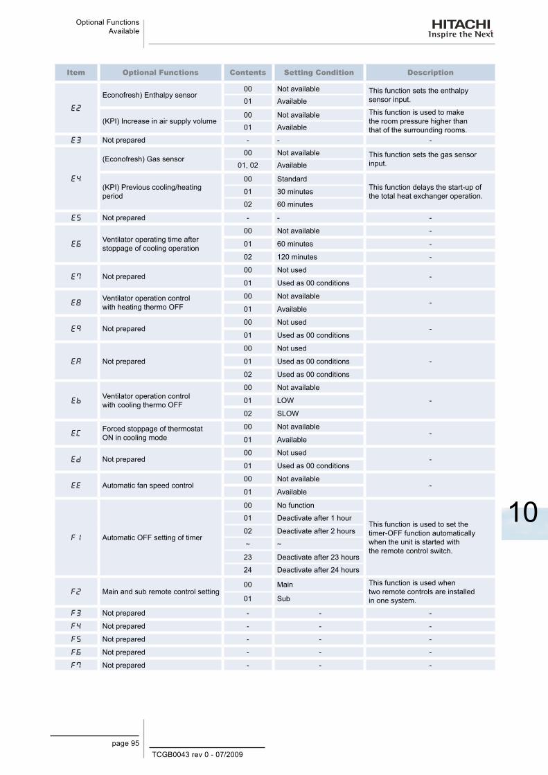
TCGB0043 rev 0 - 07/2009page 95
Optional Functions Available
10
Item Optional Functions Contents Setting Condition Description
E
Econofresh) Enthalpy sensor00 Not available This function sets the enthalpy
sensor input.01 Available
(KPI) Increase in air supply volume00 Not available This function is used to make
the room pressure higher than that of the surrounding rooms.01 Available
E Not prepared - - -
E
(Econofresh) Gas sensor00 Not available This function sets the gas sensor
input.01, 02 Available
(KPI) Previous cooling/heating period
00 StandardThis function delays the start-up of the total heat exchanger operation.01 30 minutes
02 60 minutes
E Not prepared - - -
EVentilator operating time after stoppage of cooling operation
00 Not available -
01 60 minutes -
02 120 minutes -
E Not prepared00 Not used
-01 Used as 00 conditions
EVentilator operation control with heating thermo OFF
00 Not available-
01 Available
E Not prepared00 Not used
-01 Used as 00 conditions
EA Not prepared
00 Not used
-01 Used as 00 conditions
02 Used as 00 conditions
EVentilator operation control with cooling thermo OFF
00 Not available
-01 LOW
02 SLOW
EForced stoppage of thermostat ON in cooling mode
00 Not available-
01 Available
Ed Not prepared00 Not used
-01 Used as 00 conditions
EE Automatic fan speed control00 Not available
-01 Available
F Automatic OFF setting of timer
00 No function
This function is used to set the timer-OFF function automatically when the unit is started with the remote control switch.
01 Deactivate after 1 hour
02 Deactivate after 2 hours
~ ~
23 Deactivate after 23 hours
24 Deactivate after 24 hours
F Main and sub remote control setting00 Main This function is used when
two remote controls are installed in one system.01 Sub
F Not prepared - - -
F Not prepared - - -
F Not prepared - - -
F Not prepared - - -
F Not prepared - - -
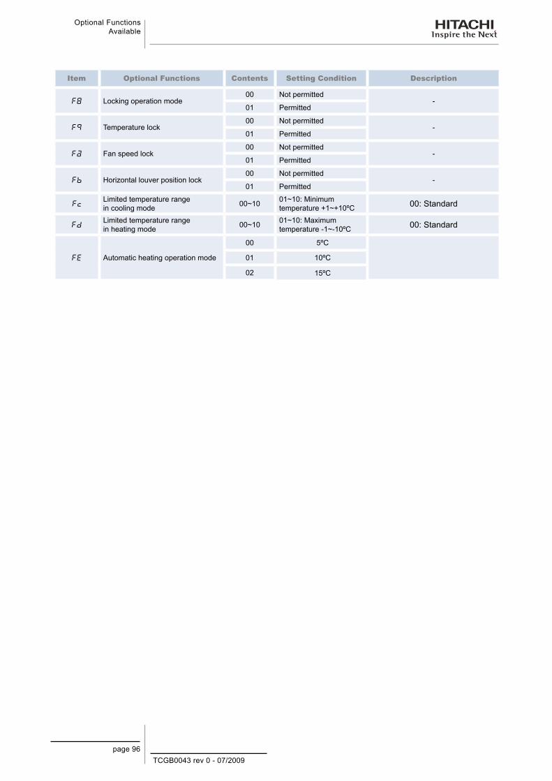
TCGB0043 rev 0 - 07/2009
Optional Functions Available
page 96
Item Optional Functions Contents Setting Condition Description
F Locking operation mode00 Not permitted
-01 Permitted
F Temperature lock00 Not permitted
-01 Permitted
Fa Fan speed lock00 Not permitted
-01 Permitted
F Horizontal louver position lock00 Not permitted
-01 Permitted
FcLimited temperature range in cooling mode 00~10 01~10: Minimum
temperature +1~+10ºC 00: Standard
FdLimited temperature range in heating mode 00~10 01~10: Maximum
temperature -1~-10ºC 00: Standard
FE Automatic heating operation mode
00 5ºC
01 10ºC
02 15ºC

TCGB0043 rev 0 - 07/2009pag. 97
Troubleshooting
11
11. Tr o u b l e s h o o t i n g
This chapter provides you with a concise description of the most common alarm codes of the new RASC-H(V)RNE series
Contents
11. Troubleshooting .......................................................................................................9711.1. Alarm Codes .......................................................................................................................................... 98

TCGB0043 rev 0 - 07/2009
Troubleshooting
pag. 98
If RUN lamp flashes for 2 seconds, there is a failure in transmission between the indoor unit and the remote control switch. Possible causes are:
The remote cable is broken −Contact failure in remote control cable −IC or microcomputer defective −In all cases, contact your service contractor −
In RUN lamp flashes 6 times (5 seconds) with unit number and alarm code displayed
NOTEThe alarm code displayed (see table below) and contact your service provider.
Alternate indication every second
Indoor unit number
Alarm code Model code
No. of indoor units connected
Alarm code
Model CodeIndication Description
Heat-pump InverterF Multi (Set-free) Cooling onlyE Others Twin, triple and quad
11.1. Alarm Codes
Code No. Category Type of Abnormality Main Cause01 Indoor unit Activation of protection device Float switch activated.
02RASC unit or Power source
Activation of protection device or Abnormality of power source wiring
Activation of: PSH, Float Switch, Magnetic Circuit Braker (Fan line 10 HP only), Locked Motor or Incorrect wiring (wrong phase connection).
03Transmission
Abnormality between indoor (or RASC unit) and RASC unit (or indoor) units
Incorrect wiring. Failure of PCB. Tripping of fuse. Power supply OFF.
04 Abnormal operation between inverter and control PCB Transmission failure between inverter PCBs.
06 Voltage drop Voltage drop due to excessively low or high voltage in RASC unit
Voltage drop in power supply. Incorrect wiring or insufficient capacity of power supply wiring.
07Cycle
Drop in discharge gas overheating Excessive refrigerant charge. Expansion valve lock open.
08 Increase in discharge gas temperature Insufficient refrigerant charge, refrigerant leakage. Expansion valve closed or clogged.
11
Sensor in indoor unit
Inlet air thermistor
Failure of thermistor, sensor, connection12 Outlet air thermistor13 Anti-freeze thermistor14 Gas pipe thermistor19 Protection device for fan motor is triggered Failure of fan motor.20
Sensor on RASC unit
Compressor thermistorFailure of thermistor, sensor, connection.22 Outside air thermistor
24 Evaporation thermistor
31
System
Incorrect setting of RASC unit and indoor units Incorrect setting of capacity code
35 Incorrect setting of indoor unit number Duplication of indoor unit number.
38 Abnormality of protective circuit in RASC unit unit Failure of indoor unit PCB; incorrect wiring; connection to indoor unit PCB.
41
Pressure
Overload cooling (possible activation of high pressure device)
RASC unit pipe thermistor temp. is higher than 55ºC and the compressor top temp. is higher than 95ºC, RASC unit protection device is activated.
42Heating overload(high-pressure device may be activated)
If I.U. freeze protection thermistor temp. is higher than 55ºC and compressor top temp. is higher than 95ºC, RASC unit protection device is activated.
47 Enabling of protection device for low pressure drop
Stoppage due to excessive decrease of evaporating temperature (Tem < -35ºC) is activated 3 times in one hour, motor locked in heating operation.

TCGB0043 rev 0 - 07/2009pag. 99
Troubleshooting
11
Code No. Category Type of Abnormality Main Cause
48
Inverter
Activation of overcurrent protectionClogging of heat exchanger. Locked compressor. Excessive refrigerant charge, Failure of Inverter PCB.
51 Abnormality in inverter current sensor Failure of Control PCB or Inverter PCB.
53 Activation for protection of InverterInverter PCB AbnormalityCompressor failure, heat exchanger clogged.
54 Inverter fin temperature increase
Abnormal inverter fin thermistorHeat exchanger clogged.Abnormal RASC unit fan.Failure of Fan Motor.
55 Inverter Abnormality Failure of Inverter PCB.
59 Inverter fin temperature increase Loose disconnected, broken or short-circuit connector.
b1 Indoor unit No. setting Incorrect unit No. setting Over 64 indoor units, setting by refrigerant cycle
No. or indoor unit address.
EE Compressor Compressor protection alarm Compressor failure.
Alarm Codes (Cont.) ¡


TCGB0043 rev.0 - 07/2009 - Printed in Spain
Hitachi Air Conditioning Products (M) Sdn. Bnd.Lot No. 10, Jalan Kemajan Bangi Industrial Estate43650 Bandar Baru Bangi, Selangor Darul Ehsan, MalaysiaCertification ISO 9001, MalaysiaCertification ISO 14001, Malaysia
HitachiAir Conditioning Products Europe, S.A.Ronda Shimizu,1 - Políg. Ind. Can Torrella08233 Vacarisses (Barcelona) EspañaISO 9001 Certified byAENOR, SpainISO 14001 Certified byAENOR, Spain
HITACHI is participating in the EUROVENT Certification Programme.Products are as specified in the EUROVENT Directory of CertifiedProducts.
Hitachi Appliances, Inc.Shimizu shi, ShizuokaISO 9001 Certified by JQA, Japan
- -ken, Japan
ISO 14001 Certified by JQA, Japan