ut66003633 - 00 - daikin · comando a microprocessore per installazione a parete legenda dei...
TRANSCRIPT
BLDC fan coil units
English language: Original InstructionsAll other language: Translation of the Original Instruction
BRUSHLESS MOTORSupplementary sheet English
Deutsch
Français
Español
MOTORE BRUSHLESSScheda integrativa Italiano
SUPPLEMENTARY SHEET
BLDC
0.50.25
100
1550
1450
1350
1250
1150
1050
950
850
Speed = (Vin - 0.5)* K+100
Speed[Rpm]
IN[0 ÷ 10V]
1 2 3 4ON
Alarm types LED indications Alarm indications DIP4=OFF Actions Notes
Over temperature
Blink alarm LED 3s ON 0,5s OFF
Blink alarm output 3s ON 0,5s OFF Motor OFF
Autoreset alarm. After about 1,5 min of persistance condition the alarm is set
permanently: LED ON, Alarm ON and system is in STOP mode
Over voltage
Under voltage
Over current
Over load Blink alarm LED 0,5s ON 0,5s OFF
Blink alarm output 0,5s ON 0,5s OFF Speed reduction
Power limiting
Safety control Temperature limiting
Stop Alarm LED ON permanently
Alarm LED ON permanently Motor OFF Set 0V ON input to reset the alarms
2 3
1
4

BLDCFan coil units
Supplementary sheetUT66003633 - 00
Brushless
Scheda integrativa
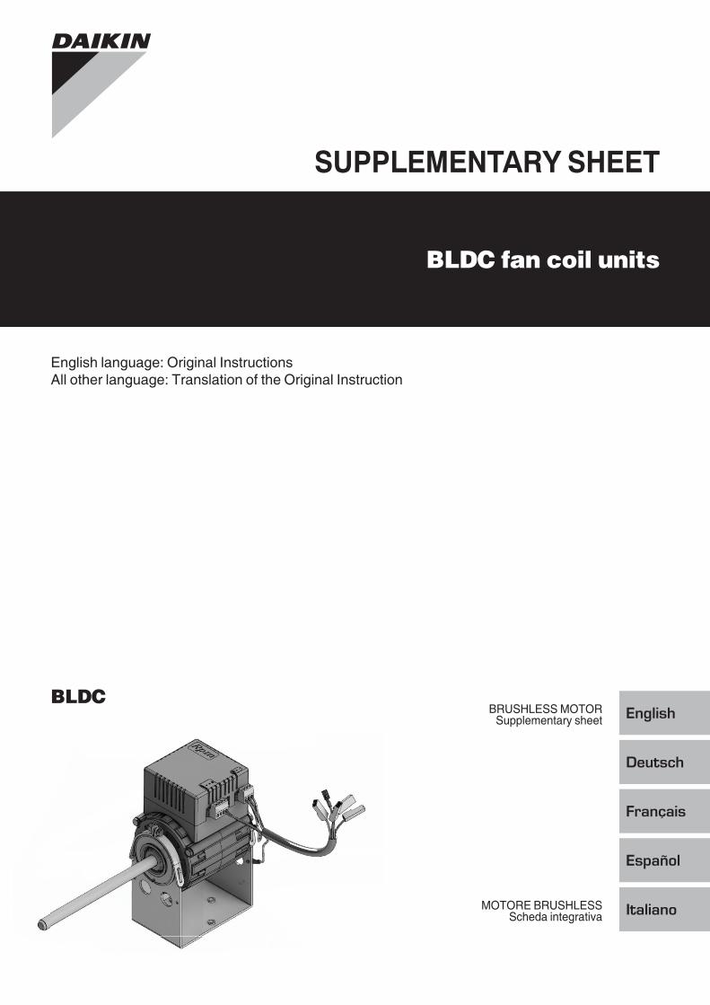
Schemi elettrici di collegamento FWec3
Comando a microprocessore per installazione a parete
legenda dei Simboli degli Schemi elettrici (Figura 1)Vo Velocità SuperminimaV1 Velocità MinimaV2 Velocità MediaV3 Velocità MassimaL FasePE TerraN NeutroRE Resistenza ElettricaSW Sonda AcquaSA Sonda AriaSU Sonda UmiditàDI1 Ingresso digitale 1DI2 Ingresso digitale 2CI12 Comune ingressi digitaliA/B/GND RS 485F Fusibile (non fornito)IL Interruttore di linea (non fornito)VC Valvola solenoide RaffreddamentoVH Valvola solenoide Riscaldamento….. Collegamenti elettrici a cura dell'installatore101 Uscita 0-10V 1COM Comune uscite 0-10V102 Uscita 0-10V 2DO2 Uscita digitale 2DO1 Uscita digitale 1CO12 Comune uscite digitali
Per ogni ventilconvettore prevedere sulla rete di alimentazione un interruttore (IL) con contatti di apertura con distanza di almeno 3mm e un fusibile (F) di protezione adeguato.
Collegare al massimo 20 terminali BLDC ad un unico interruttore differenziale.
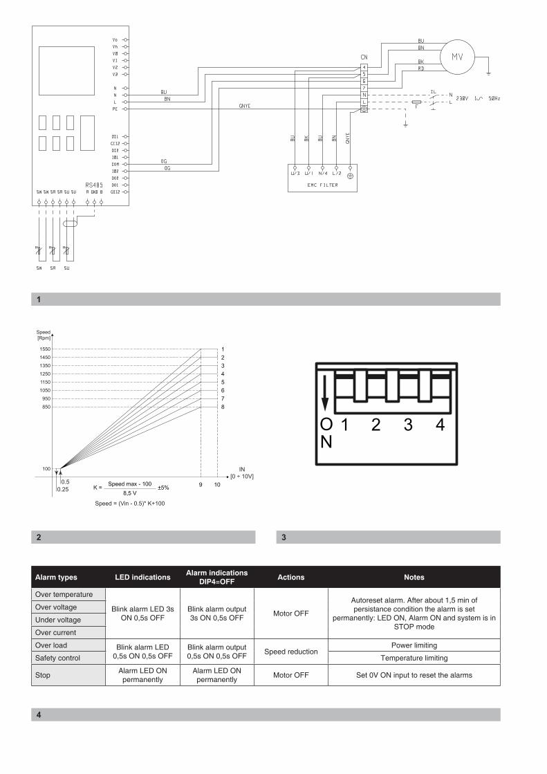
caratteriStiche di regolazione dell'inverter (Figura 2)Il settaggio della curva richiesta può essere effettuato in fabbrica (e modificato in cantiere se necessario) mediante impostazione dei dip switch.
tabella di Selezione dellle rampe di velocità (Figura 3)
N° Velocità MAX DIP 1 DIP 2 DIP 3 DIP 4
1 1550 rpm OFF OFF OFF -
2 1450 rpm ON OFF OFF -
3 1350 rpm OFF ON OFF -
4 1250 rpm ON ON OFF -
5 1150 rpm OFF OFF ON -
6 1050 rpm ON OFF ON -
7 950 rpm OFF ON ON -
8 850 rpm ON ON ON -
La velocità massima (1550 rpm) non viene utilizzata.
allarmi (Figura 4)
Brushless
Supplementary sheet
Wiring diagramS FWec3
Wall-mounted microprocessor control
Key to SymbolS uSed in Wiring diagramS (Figure 1)Vo Extra-low speedV1 Minimum speedV2 Medium speedV3 Maximum speedL PhasePE GroundN NeutralRE Heating elementSW Water sensorSA Air sensorSU Humidity ProbeDI1 Digital 1 inputDI2 Digital 2 inputCI12 Digital input commonA/B/GND RS 485F Fuse (not supplied)IL Circuit breaker (not supplied)VC Solenoid valve - CoolingVH Solenoid valve - Heating….. Electrical connections to be made by installer101 0-10V 1 OutputCOM 0-10V Output Common102 0-10V 2 OutputDO2 Digital 2 outputDO1 Digital 1 outputCO12 Digital output Common
Each fan-coil requires a switch (IL) on the feeder line with a distance of at least 3 mm between the opening contacts, and a suitable safety fuse (F).
Connect up to 20 BLDC terminals to a single differential circuit breaker.
inverter characteriSticS oF regulation (Figure 2)The full speed curve setting can be factory made (modified on site if necessary) by using the dip switches on the mail board.
Full Speed Selection table (Figure 3)
N° MAX speed DIP 1 DIP 2 DIP 3 DIP 4
1 1550 rpm OFF OFF OFF -
2 1450 rpm ON OFF OFF -
3 1350 rpm OFF ON OFF -
4 1250 rpm ON ON OFF -
5 1150 rpm OFF OFF ON -
6 1050 rpm ON OFF ON -
7 950 rpm OFF ON ON -
8 850 rpm ON ON ON -
Max speed (1550 rpm) is not used.
alarmS (Figure 4)

UT66003633 - 00Zandvoordestraat 300, B-8400 Oostende, Belgium