using zynq-7000 soc iec 61508 artifacts to achieve iso ... · wp495 (v1.0) november 21, 2017 2...
TRANSCRIPT

WP495 (v1.0) November 21, 2017 www.xilinx.com 1
© Copyright 2017 Xilinx, Inc. Xilinx, the Xilinx logo, Artix, ISE, Kintex, Spartan, Virtex, Vivado, Zynq, and other designated brands included herein are trademarks of Xilinx in the United States and other countries. AMBA, AMBA Designer, ARM, ARM1176JZ-S, CoreSight, Cortex, and PrimeCell are trademarks of ARM in the EU and other countries. All other trademarks are the property of their respective owners.
This white paper shows functional safety professionals how to leverage Zynq®-7000 All Programmable SoCs based artifacts and architecture for their ISO 13849 requirements, lowering certification costs and decreasing time to market.
White Paper: Zynq-7000 SoC, ISO 13849, IEC 61508 Standards
WP495 (v1.0) November 21, 2017
Using Zynq-7000 SoC IEC 61508 Artifacts
to Achieve ISO 13849 ComplianceBy: Paul S. Levy
ABSTRACTThe Zynq-7000 All-Programmable SoC is the industry's first SoC with integrated programmable logic that enables functional safety professionals to increase safety-related system quality by using the power of diversity available on a single device. This capability lowers the overall customer investment by providing the on-chip subsystem independence of programmable logic and an ARM® Cortex™-A9, while increasing the overall systemic capability of customer solutions due to the diversity inherent in the Zynq-7000 architecture.All performance levels of ISO 13849 can be supported using a single Zynq-7000 device, including two-channel requirements for Cat. 3 and Cat. 4 solutions. Built-in diagnostics in both the processor subsystem and programmable logic lower, and in some cases replace, customer-designed diagnostics.This white paper gives an overview of the challenges and strategies each ISO 13849 Performance Level solution needs for certification and how Zynq-7000 SoC solutions enable faster time-to-market.

WP495 (v1.0) November 21, 2017 www.xilinx.com 2
Using Zynq-7000 SoC IEC 61508 Artifacts to Achieve ISO 13849 Compliance
IntroductionIn the world of functional safety, IEC 61508 is considered the parent standard that establishes the basic principles used in all other safety-related specifications. Inasmuch as it is generic in nature, IEC 61508 was intended to be a reference for various industry sectors to be used as a guideline for their own specific standards.
IEC 61508 provides detailed guidance for the entire safety-related system's life cycle, from inception to decommission; it is the go-to specification for safety-related electrical/electronic or programmable products.
In those cases where the scope extends beyond pure electrical and/or electronic systems, ISO 13849 comes into play with IEC/EN 62061 applying to programmable electronic control systems.
ISO 13849 is the international standard that outlines the general principles and specific requirements for design and implementation of safety-related parts of machinery control systems. It is applicable to hydraulic, pneumatic, and electromechanical systems, in addition to some programmable electronic systems.
IEC/EN 62061 is the machinery-specific implementation of IEC/EN 61508. IEC/EN 62061 provides requirements for system-level design of all types of safety-related machinery/electrical systems.
For the electrical/electronic or programmable elements, there is considerable overlap between ISO 13849 and IEC 61508 to the extent that elements already designed to the IEC 61508 standard can be mapped to ISO 13849 quality metrics.
This white paper focuses on architectural aspects and does not cover systematic concerns. Refer to ISO 13849-2 for a comprehensive list of applicable measures against systematic failures.
NomenclatureIn IEC 61508 and IEC/EN 62061, the quality metric for a safety-related system is the safety integrity level (SIL). The SIL levels range from 1 through 4 (the higher the level, the higher the quality of the system).
In ISO 13849, two metrics are used. The first is the performance level (PL), where the rating is PLa, PLb, PLc, PLd, and PLe, where PLe is the highest quality. Within each performance level, there is a category metric defined as Cat. B, Cat. 1, Cat. 2, Cat. 3, or Cat. 4. Each category defines the architecture of the solution, with Cat. 4 being the most reliable. Not all categories are suitable for implementation within all performance levels, however. For example, PLe cannot be implemented using Cat. 1 architecture, but can be implemented using either Cat. 3 or Cat. 4 depending on other factors.
This white paper considers only those implementations where the performance level and category are known. For a given system performance-level requirement (PLr), each element's performance level must be equal or greater than the PLr. Figure 1 shows that the performance level for each element is the result of the category, diagnostic coverage (DC), mean time to dangerous failure (MTTFd), and common cause failures (CCF). In other words, the intersection of Cat, DC, MTTFd, and CCF are used to justify the performance level for each element.

WP495 (v1.0) November 21, 2017 www.xilinx.com 3
Using Zynq-7000 SoC IEC 61508 Artifacts to Achieve ISO 13849 Compliance
Zynq-7000 All-Programmable SoCImplementing safety functions using the Zynq-7000 SoC with Xilinx’s Vivado® Design Suite's TÜV SÜD certified tool chain makes meeting ISO 13849 straightforward. These products contain two independent or interdependent subsystems: (1) The processing system (PS) contains two ARM Cortex-A9 CPUs with supporting Level 2 cache memory, DDR memory controller, and I/O blocks; (2) The programmable logic subsystem contains FPGA logic and integrated logic functions.
Each of these subsystems can be used independently or in concert with each other, depending on safety requirements. Xilinx’s Vivado tools that support Zynq-7000 SoC designs are certified for functional safety application development in accordance with IEC 61508.
For PLr of PLe, solutions, specification requirements can be mapped directly into SIL3 IEC 6150. See Figure 2.
X-Ref Target - Figure 1
Figure 1: Performance Level Relationship to Cat, DC, and MTTFd
A
PL
(Per
form
ance
Lev
el)
Cat. B Cat. 1 Cat. 2 Cat. 2 Cat. 3 Cat. 3 Cat. 4- DC avg none- One Channel
- DC avg none- One Channel
- DC avg none- One Channel +- Test Chennel
- DC avg Med- One Channel +- Test Chennel
- DC avg Low- Two Channel
- DC avg Med- Two Channel
- DC avg High- Two Channel
B
C
D
E
WP495_01_110717
MTTFd/Channel = LowMTTFd/Channel = MedMTTFd/Channel = High

WP495 (v1.0) November 21, 2017 www.xilinx.com 4
Using Zynq-7000 SoC IEC 61508 Artifacts to Achieve ISO 13849 Compliance
Table 1 shows how certified Vivado tools can help satisfy general design requirements. The tools and support documentation help quantify FIT rates in the PS and/or the logic based on the device and resources required by the safety function.
When using the Zynq-7000 SoC as a logic solver, the capability to support PLe exists because Cat. 4 can be implemented using hardware independence on the same device, creating the two independent channels required. This is accomplished on the Zynq-7000 SoC design, which supports HFT=1 based on IEC 61508, Part 2, Annex E.
In addition to the custom FMEDA diagnostics, Xilinx also provides on-chip diagnostic logic on several PS subsystems: L1 and L2 cache (parity) and on-chip memory (parity)—as well as logic subsystems: configuration RAM (ECC) and block RAM (ECC) diagnostics. Xilinx provides documentation enabling quantitative analysis of each subsystem, based on the customer’s use case.
Performance-Level AnalysisWith respect to ISO 13849 performance-level evaluation, in most cases, multiple categories can yield the desired performance level. Typically, the performance-level requirement is accompanied by the category that helps narrow implementation requirements.
X-Ref Target - Figure 2
Figure 2: Zynq-7000 Functional Architecture
Table 1: Performance Level to SIL Map
Performance level (PL)
PFH: Per-hour [1/x] average probability of dangerous failure
SIL (IEC 61508 / IEC 62061)
a ≥ 10–5 to < 10–4 No correspondence
b ≥ 3 x 10⁻⁶ to < 10–5 1
c ≥ 10–6 to < 3 x 10⁻⁶ 1
d ≥ 10–7 to < 10–6 2
e ≥ 10–8 to < 10–7 3
Category
MT
TF
dP
er Channel
CCF
DCavg
PLa
PLb
B 1 2 2 3 3 4
NA Yes Yes Yes Yes Yes
None Low Med Low Med
PLa PLb PLb PLc
PLb PLc PLc PLd
PLc PLc PLd PLd PLd
High
PLe
NA
None
Med
High
Low
WP495_02_100217
Category
MT
TF
dP
er Channel
CCF
DCavg
PLa
PLb
B 1 2 3 3 4
NA Yes Yes Yes
None Low Med
PLa PLb PLb PLc
PLb PLc PLc PLd
PLc PLc PLd PLd PLd
High
PLe
NA
None
Med
High
Low
Yes
Med
2
Yes
Low

WP495 (v1.0) November 21, 2017 www.xilinx.com 5
Using Zynq-7000 SoC IEC 61508 Artifacts to Achieve ISO 13849 Compliance
CategoryIn ISO 13049, category defines the architecture of the implementation with respect to hardware redundancy.
Mapping Zynq-7000 SoC capabilities into category requirements is straightforward based on ISO 13849, Part 1, Clause 6.2.
• For Cat. B and Cat. 1, a single-channel implementation of the logic solver, the Zynq-7000 SoC solutions can use either the PS, the programmable logic, or a combination of the two to implement the safety function.
• For Cat. 2, a testing unit is added for verification of the operation of the safety function. Implementation of the testing unit requires isolation, so if the testing unit fails, it will not interfere with the safety channel's operation. Conversely, if the safety function fails, it should not interfere with the testing unit's operation. Since the Zynq-7000 SoC has two independent resources (the PS and the programmable logic), the testing unit can be implemented in the resource that is not being used for the safety function.
• For Cat. 3 and Cat. 4, redundancy is required with cross-channel monitoring. When using the Zynq-7000 SoC, each of the two safety channels is implemented in an independent resource, i.e., one safety channel in the PS and the other safety channel in the programmable logic.
MTTFd (Mean Time to Dangerous Failure)In ISO 13849, MTTFd per channel is defined as low, medium, or high with metrics as outlined in Table 2.
Using FIT, a number can be assigned based on the boundary of the index required in Table 3.
For Zynq-7000 SoCs, total dangerous FIT is the sum of one-half the permanent failure rate minus diagnostic credit plus one-half the transient failure rate minus diagnostic credit of those resources used to implement the safety function. The one-half scaling factor is used due to the assumption of 50% safe failures and 50% dangerous failures.
Total Dangerous FIT = 1/2 [ (PFR · (1 – DC%)) + (TFR · (1 – DC%)) ]
Table 2: MTTFd Index to Time
Index Range (Time)Low 3 Years < MTTFd < 10 Years
Medium 10 Years < MTTFd < 30 years
High 30 Years < MTTFd < 100 Years
Table 3: MTTFd Index to FIT Rate
Index Range (Failure Rate)Low 38,052 FIT < MTTFd < 11,416 FIT
Medium 11,416 FIT < MTTFd < 3,805 FIT
High 3,805 FIT < MTTFd < 1,142 FIT

WP495 (v1.0) November 21, 2017 www.xilinx.com 6
Using Zynq-7000 SoC IEC 61508 Artifacts to Achieve ISO 13849 Compliance
wherePFR = Permanent Failure RateDC% = Diagnostic Coverage %TFR = Transient Failure Rate
Zynq-7000 SoC Permanent FITXilinx publishes device reliability reports to the public twice a year titled UG116, Device Reliability Report. This report details ongoing reliability testing, including family FIT rates. Based on all 7 series data available in these reports (UG116 2nd half 2015 and UG116 1st half 2016), the permanent FIT for 7 series and Zynq-7000 SoC is 9 FIT. Based on the size of the Zynq-7000 device, permanent FIT currently ranges from 2 FIT for the smallest device to 11 FIT for the largest device based on 100% utilization. Dangerous permanent FIT is half of the permanent FIT, which then becomes 1 to 5.5 FIT at 100% utilization.
Zynq-7000 SoC Transient FITAt Xilinx, arrays of block RAM and configuration RAM are used to create the functions in Xilinx programmable devices. For example, referring to the UG116 2nd Half report, the transient FIT for Zynq-7000 SoC is 66 FIT/Mb for block RAM and 72 FIT/Mb for configuration RAM.
For the largest Zynq-7000 SoC, the 7-Z100, the combined dangerous transient FIT for logic plus mitigated block RAM and mitigated configuration RAM at 100% utilization is significantly less than the 3,805 FIT required. Clearly 3,805 FIT is the boundary for the whole machine; thus, it is imperative that the Zynq-7000 SoC contributes at its minimum to the overall dangerous FIT.
Mitigation for configuration RAM and block RAM requires using the Xilinx-supplied built-in ECC for the block RAM and configuration RAM coverage strategies, such as the SEM-IP infrastructure.
Diagnostic Coverage (DC)Diagnostic coverage refers to methods and measures used to diagnose and sometimes correct a dangerous failure. It is defined as:
DC = (Detected Dangerous Faults) / (Total Dangerous Faults)
WP495 (v1.0) November 21, 2017 www.xilinx.com 7
Using Zynq-7000 SoC IEC 61508 Artifacts to Achieve ISO 13849 Compliance
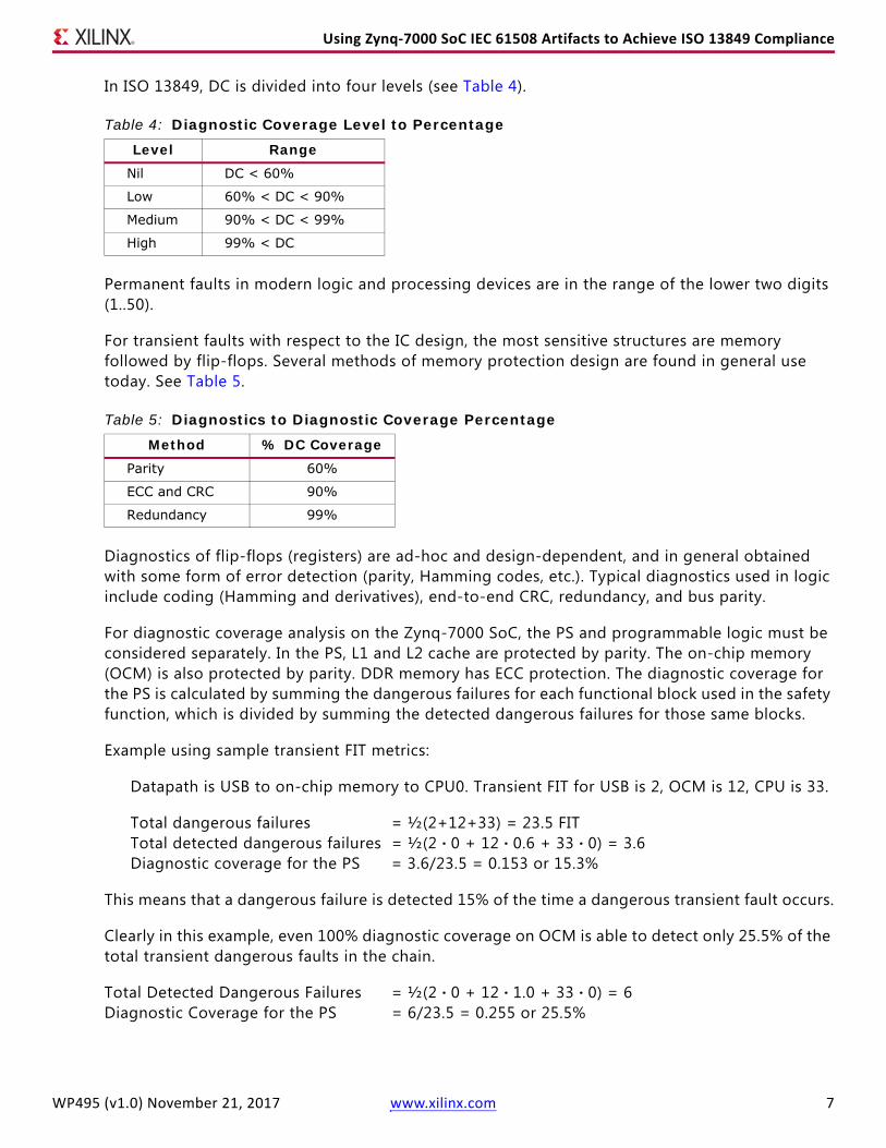
In ISO 13849, DC is divided into four levels (see Table 4).
Permanent faults in modern logic and processing devices are in the range of the lower two digits (1..50).
For transient faults with respect to the IC design, the most sensitive structures are memory followed by flip-flops. Several methods of memory protection design are found in general use today. See Table 5.
Diagnostics of flip-flops (registers) are ad-hoc and design-dependent, and in general obtained with some form of error detection (parity, Hamming codes, etc.). Typical diagnostics used in logic include coding (Hamming and derivatives), end-to-end CRC, redundancy, and bus parity.
For diagnostic coverage analysis on the Zynq-7000 SoC, the PS and programmable logic must be considered separately. In the PS, L1 and L2 cache are protected by parity. The on-chip memory (OCM) is also protected by parity. DDR memory has ECC protection. The diagnostic coverage for the PS is calculated by summing the dangerous failures for each functional block used in the safety function, which is divided by summing the detected dangerous failures for those same blocks.
Example using sample transient FIT metrics:
Datapath is USB to on-chip memory to CPU0. Transient FIT for USB is 2, OCM is 12, CPU is 33.
Total dangerous failures = ½(2+12+33) = 23.5 FITTotal detected dangerous failures = ½(2 · 0 + 12 · 0.6 + 33 · 0) = 3.6Diagnostic coverage for the PS = 3.6/23.5 = 0.153 or 15.3%
This means that a dangerous failure is detected 15% of the time a dangerous transient fault occurs.
Clearly in this example, even 100% diagnostic coverage on OCM is able to detect only 25.5% of the total transient dangerous faults in the chain.
Total Detected Dangerous Failures = ½(2 · 0 + 12 · 1.0 + 33 · 0) = 6Diagnostic Coverage for the PS = 6/23.5 = 0.255 or 25.5%
Table 4: Diagnostic Coverage Level to Percentage
Level RangeNil DC < 60%
Low 60% < DC < 90%
Medium 90% < DC < 99%
High 99% < DC
Table 5: Diagnostics to Diagnostic Coverage Percentage
Method % DC CoverageParity 60%
ECC and CRC 90%
Redundancy 99%

WP495 (v1.0) November 21, 2017 www.xilinx.com 8
Using Zynq-7000 SoC IEC 61508 Artifacts to Achieve ISO 13849 Compliance
A couple of things can dramatically improve the diagnostic coverage. First, using an end-to-end protocol checksum—for example CRC. In this case, the path of USB up to the OCM is fully covered, because the transient faults are independent events following, in general, a Poisson distribution (rare events). Most of the errors can be safely mitigated by exploiting the CRC of the USB packet. In this case, the worst condition is on address packets that use a CRC-5 (five bits). This gives 1-2-5= 0.968 or 97% detection capability.
For the programmable logic, the diagnostic coverage calculation needs to take into account the transient FIT rate of logic, block RAM, and configuration RAM used to implement the safety function. Based on analysis, the diagnostic coverage for any implementation of a safety function in the PL supports a level of Medium, provided the Xilinx built-in diagnostics are enabled.
Since the CPU and the programmable logic are in separate domains, using the programmable logic as a diagnostic for the CPU does not require additional common cause failure analysis outside considerations of IEC61508 Part2 Annex-E. This method of comparing results between the CPU and programmable logic is called reciprocal comparison by software. The diagnostic coverage can be as much as 99% based on the hamming distance of the comparison and the associated logic that drives the result. The diversity between the CPU and the programmable logic serves to enhance the diagnostic coverage of systematic faults that can be present in the safety function.
From above, Transient FIT for USB is 2, OCM is 12, CPU is 33.
Total Detected Dangerous Failures = ½(2 · 0.96 + 12 · 0.96 + 33 · 0.95) = 22.4Diagnostic Coverage for the PS = 22.4/23.5 = 0.953 or 95.3%
The final diagnostic coverage is much in line with the expectations for the Medium toward the Highest boundary.
Common Cause Failure (CCF)In the previous example, it was shown that CCF becomes important at higher categories when redundancy is required. Implementing redundancy on a single chip becomes problematic if the failure rate of common causes, defined as β, becomes too large. In ISO 13849, CCF analysis refers to Annex F, which needs to be applied at the system level. IEC/EN 62061 does not provide enough clarity about defining channel independence on a single chip.
When two safety channels exist on a single chip, the most appropriate reference is IEC 61508-2, Annex E. This annex defines βic and the maximum amount of CCF allowed, which is 25%. For the Zynq-7000 SoC, there is significant independence between the PS and programmable logic subsystems that supports a low enough βic. This qualifies the Zynq-7000 SoC to support two safety channels on the same chip, as long as one safety channel is in the PS and the second is in the programmable logic.

WP495 (v1.0) November 21, 2017 www.xilinx.com 9
Using Zynq-7000 SoC IEC 61508 Artifacts to Achieve ISO 13849 Compliance
Performance Level AssignmentsThe definitions needed for a performance level have been reviewed; the options needed to support a particular performance level are examined next.
PLaTwo options exist to achieve this performance level for PLa, as shown in Figure 3.
The difference between Cat. B and Cat. 2 derives from the rule that the higher the category, the more resilient the safety function. In the case of Cat. B, any single failure could stop the safety function from operating with no added benefit of sensor or actuator supervision. In the case of Cat. 2, diagnostic proof testing is added to detect a functional safety failure, and actuator monitoring and redundancy are added.
For PLa elements, the logic solver's requirements have no diagnostic coverage requirements and a MTTFd of at least 3 years. This translates to a failure rate of less than 38,052 FIT. With about 20% of CRAM used in the programmable logic, the Zynq-7000 Z-7020 device has a failure rate of approximately 23 FIT. Using a budget of 10% for PLa, the target is 3805 FIT. So the FIT budget is easily met by a wide margin.
For the PLa Cat. 2, a diagnostic coverage of Low is required for the channel. Looking at the PS memory resources, cache, and OCM, simple mechanisms like parity and checking can easily deliver the required coverage. In general state machines, the logic can easily be configured for high-level diagnostics just by designing the state machines with proper Hamming distance. This is the fastest and easiest method, and it consumes little extra logic.
X-Ref Target - Figure 3
Figure 3: PLa OptionsWP495_03_110217
Category
MT
TF
dP
er Channel
CCF
DCavg
PLa
PLb
B 1 2 2 3 3 4
NA Yes Yes Yes Yes Yes
None Low Med Low Med
PLa PLb PLb PLc
PLb PLc PLc PLd
PLc PLc PLd PLd PLd
High
PLe
NA
None
High
Med
Low
Category
MT
TF
dP
er Channel
CCF
DCavg
PLa
PLb
B 1 2 3 3 4
NA Yes Yes Yes Yes
None Med Low Med
PLa PLb PLb PLc
PLb PLc PLc PLd
PLc PLc PLd PLd PLd
High
PLe
NA
None
High
Med
2
Yes
Low
Low
PLa Option 1 PLa Option 2

WP495 (v1.0) November 21, 2017 www.xilinx.com 10
Using Zynq-7000 SoC IEC 61508 Artifacts to Achieve ISO 13849 Compliance
PLbFor PLb elements, there are four options to obtain a PLb solution (see Figure 4).
The options range from Cat. B to Cat. 3 and inversely from a failure rate of less than 11,416 FIT (for an MTTFd of Medium), to a failure rate of less than 38,052 FIT (for an MTTFd of Low).
The total FIT rate allowed decreases from 38,052 FIT to 11,416 FIT. This lower FIT rate is easily met by the largest Zynq-7000 SoC components off the shelf by implementing Xilinx's onboard parity and ECC diagnostics.
PLcThere are five ways to implement a PLc solution (Figure 5). The total FIT rate allowed decreases from 11,416 FIT to 3,805 FIT, or the probability of a failure every 30 years when using Cat. 1 architecture (Cat B. plus proven components and safety principles). The architecture also changes to include diagnostic proof testing that bounds fault detection.
X-Ref Target - Figure 4
Figure 4: PLb Options
Category
MT
TF
dP
er Channel
CCF
DCavg
PLa
PLb
2 2 3 3 4
NA Yes Yes Yes Yes Yes
None Low Med Low Med
PLa PLb PLb PLc
PLb PLc PLc PLd
PLc PLc PLd PLd PLd
High
PLe
NA
None
Low
High
PLb Option 1 PLb Option 2
1
Med
B Category
MT
TF
dP
er Channel
CCF
DCavg
PLa
PLb
B 1 3 4
NA Yes Yes
None Med
PLa PLb PLb PLc
PLb PLc PLc PLd
PLc PLc PLd PLd PLd
High
PLe
NA
None
Low
Yes
Low
High
2
Yes
Med
Med
Yes
Low
32
WP495_04_110217
PLb Option 3
Category
MT
TF
dP
er Channel
CCF
DCavg
PLa
PLb
B 1 3 4
NA Yes Yes
None Med
PLa PLb PLb PLc
PLb PLc PLc PLd
PLc PLc PLd PLd PLd
High
PLe
NA
None
Med
Yes
Low
High
2
Yes
Med
Low
Yes
Low
32
PLb Option 4
Category
MT
TF
dP
er Channel
CCF
DCavg
PLa
PLb
B 1 3 4
NA Yes Yes
None Med
PLa PLb PLb PLc
PLb PLc PLc PLd
PLc PLc PLd PLd PLd
High
PLe
NA
None
Med
Yes
Low
High
2
Yes
Med
Low
Yes
Low
3 3

WP495 (v1.0) November 21, 2017 www.xilinx.com 11
Using Zynq-7000 SoC IEC 61508 Artifacts to Achieve ISO 13849 Compliance
With respect to the category required in the solution, the MTTFd metric drives where the implementation is easiest.
In the case of PLc Cat. 1, the safety function fits into the PS or the programmable logic of any Zynq-7000 SoC design.
In the case of PLc Cat. 2, DC can be an issue for implementation in the PS and require that additional checkers in software be installed. CCF, in each case referencing IEC-61508, Part 2, Annex E (βic of 8%), is built into the chip as long as the PS and fabric are used, one for the safety channel and one for the test equipment.
In the case of PLc Cat. 3, the DC issue can be addressed by reciprocal comparison (or cross-channel monitoring) between the two channels. Again, CCF in each case is supported referencing IEC-61508, Part 2, Annex E, as long as the PS and programmable logic are used one each for the safety channels.
X-Ref Target - Figure 5
Figure 5: PLc Options
Category
MT
TF
dP
er Channel
CCF
DCavg
PLa
PLb
B 2 2 3 3 4
NA Yes Yes Yes Yes Yes
None Low Med Low Med
PLa PLb PLb PLc
PLb PLc PLc PLd
PLc PLc PLd PLd PLd
High
PLe
NA
None
Low
Med
High
1 Category
MT
TF
dP
er Channel
CCF
DCavg
PLa
PLb
B 1 2 3 3 4
NA Yes Yes Yes
None Low Med
PLa PLb PLb PLc
PLb PLc PLc PLd
PLc PLc PLd PLd PLd
High
PLe
NA
None
Low
Yes
Med
2
Yes
Low
Med
High
Category
MT
TF
dP
er Channel
CCF
DCavg
PLa
PLb
B 1 3 3 4
NA Yes Yes Yes
None Low Med
PLa PLb PLb PLc
PLb PLc PLc PLd
PLc PLc PLd PLd PLd
High
PLe
NA
None
Low
2
Yes
Low
High
2
Yes
Med
Med
Category
MT
TF
dP
er Channel
CCF
DCavg
PLa
PLb
B 1 3 4
NA Yes Yes
None Med
PLa PLb PLb PLc
PLb PLc PLc PLd
PLc PLc PLd PLd PLd
High
PLe
NA
None
Low
2
Yes
Low
High
2
Yes
Med
Med
Yes
Low
3
Category
MT
TF
dP
er Channel
CCF
DCavg
PLa
PLb
B 1 4
NA Yes
None
PLa PLb PLb PLc
PLb PLc PLc PLd
PLc PLc PLd PLd PLd
High
PLe
NA
None
2
Yes
Low
High
2
Yes
Med
Med
Yes
Low
3 3
Yes
Med
Low
WP495_05_110217
PLc Option 1 PLc Option 2
PLc Option 3 PLc Option 4
PLc Option 5

WP495 (v1.0) November 21, 2017 www.xilinx.com 12
Using Zynq-7000 SoC IEC 61508 Artifacts to Achieve ISO 13849 Compliance
PLdThere are four possible paths (Figure 6) for achieving PLd. Three of these paths require a FIT of 3,805. All require a level of redundancy.
Using a Zynq-7000 SoC for PLd Cat. 2 requires a DC of 90%, which is best accommodated in the programmable logic’s built-in diagnostics. Achieving a DC of 90% in the PS is possible using reciprocal comparison by software between the safety channel and the test channel. An alternative approach is to use customer-generated diagnostics, such as register state checkers and datapath end-to-end CRC.
For a Zynq-7000 SoC PLd Cat. 3 solution, the user can choose a Medium MTTFd with a High DC or a High MTTFd with Low DC. Achieving a total FIT of much less than 3,805 is accommodated by all Zynq-7000 SoC components. Achieving a DC of 90% can be addressed by reciprocal comparison using software (or cross-channel monitoring) between the two channels. The common cause failure analysis (βic) using IEC61508 Part 2 Annex-E is required to support a safety channel in the PS and a safety channel in the programmable logic. Attempting a High DC just using reciprocal comparison by software, while possible, is application-dependent and requires proper analysis to provide evidence needed for an assessor.
As an example, here is the analysis of the most popular Zynq-7000 component, the Z-7020:
• Fabric Total FIT (Z-7020 utilization = 25%) Logic 16, configuration RAM 331.7, block RAM 89.9
• Total Dangerous Failures = ½(16 + 331.7 + 89.9) = 437.6 FIT
• Total Detected Dangerous Failures = ½ (16 · 0 + 331.7 · 0.9 + 89.9 · 0.9) = 379.4 FIT
• Diagnostic Coverage for 25% utilization of the fabric = 379.4/437.6 = 0.867 or 86.7%
• Max Transient MTTFd is 116 FIT with 100% utilization
X-Ref Target - Figure 6
Figure 6: PLd OptionsWP495_06_110317
Category
MT
TF
dP
er Channel
CCF
DCavg
PLa
PLb
B 2 3 3 4
NA Yes Yes Yes Yes
None Low Low Med
PLa PLb PLb PLc
PLb PLc PLc PLd
PLc PLc PLd PLd PLd
High
PLe
NA
None
Low
Med
High
1 2
Yes
Med
Category
MT
TF
dP
er Channel
CCF
DCavg
PLa
PLb
B 2 3 4
NA Yes Yes Yes
None Low Med
PLa PLb PLb PLc
PLb PLc PLc PLd
PLc PLc PLd PLd PLd
High
PLe
NA
None
Low
Med
High
1 2
Yes
Med
3
Yes
Low
Category
MT
TF
dP
er Channel
CCF
DCavg
PLa
PLb
B 2 3 4
NA Yes Yes Yes
None Low Low
PLa PLb PLb PLc
PLb PLc PLc PLd
PLc PLc PLd PLd PLd
High
PLe
NA
None
Low
High
1 2
Yes
Med
3
Yes
Med
Med
Category
MT
TF
dP
er Channel
CCF
DCavg
PLa
PLb
B 2 3 4
NA Yes Yes Yes
None Low Low
PLa PLb PLb PLc
PLb PLc PLc PLd
PLc PLc PLd PLd PLd
High
PLe
NA
None
Low
1 2
Yes
Med
3
Yes
Med
Med
High
PLd Option 1 PLd Option 2
PLd Option 4

WP495 (v1.0) November 21, 2017 www.xilinx.com 13
Using Zynq-7000 SoC IEC 61508 Artifacts to Achieve ISO 13849 Compliance
This is a purely academic example. The actual design in the programmable logic is a percentage of logic, configuration RAM, and block RAM. The Vivado tools state exactly how much of each is used in the design.
As described in this hypothetical case, the actual diagnostic coverage by the built-in measures in the programmable logic varies based on the ratio of logic, configuration RAM, and block RAM used in the customer design. In all cases, the transient MTTFd for the programmable logic should never exceed 700 FIT. Achieving a DC of 90% can be addressed by reciprocal comparison by software (or cross-channel monitoring) between the two channels. When placing one safety channel in the PS and with the redundant safety in the programmable logic, a common cause failure analysis (βic) using IEC61508 Part 2 Annex-E is required. Attempting a High DC just using reciprocal comparison by software while possible is application dependent and requires proper analysis to provide evidence needed for an assessor.
PLeFor PLe, Cat. 4 solutions, ISO 13849 refers to IEC 61508 SIL3 with redundancy. The Zynq-7000 SoC supports single-chip hardware redundancy due to its clock, power, and physical circuit isolation spacing, which satisfies the two-channel architecture required. See Figure 7.
For MTTFd High, the FIT requirements are supported by the largest Zynq-7000 SoC component as long as the Xilinx built-in diagnostics are enabled.
The most challenging aspect of PLe is the diagnostic coverage of High. Here, several methods can be applied, including using external devices so the CCF dependencies are minimized. In this single-chip solution, the reciprocal comparison by software allows significant coverage. Other techniques can be applied to reduce the CCF even further, but a complete answer is only possible if applied to a specific application case. Proper analysis is thus necessary for providing evidence that 99% of the dangerous faults are detectable by the applied methods.
X-Ref Target - Figure 7
Figure 7: PLe
WP495_06_110217
Category
MT
TF
dP
er Channel
CCF
DCavg
PLa
PLb
B 2 3
NA Yes Yes
None Low Low
PLa PLb PLb PLc
PLb PLc PLc PLd
PLc PLc PLd PLd PLd PLe
NA
None
Low
1 2
Yes
Med
3
Yes
Med
Med
High
4
Yes
High

WP495 (v1.0) November 21, 2017 www.xilinx.com 14
Using Zynq-7000 SoC IEC 61508 Artifacts to Achieve ISO 13849 Compliance
An Example That Pulls It All TogetherUsing the Zynq-7000 SoC in Cat. 3 and Cat. 4 solutions does require a simple external element that combines diagnostics from each channel and a simple watchdog, as shown in the block diagram in Figure 8.
As with most complex programmable safety elements, external monitoring elements are combined externally using simple logic. Here, summation of the logic needed to quality the safety function with power good and the external watchdog elements is shown.
ConclusionWhen it comes to supporting ISO 13849 logic-solver elements, a Zynq-7000 SoC solution provides a straightforward path. Xilinx’s Vivado Design Suite’s certified tool chain makes the Zynq-7000 SoC's implementation of its unique architecture clear-cut, supporting all ISO 13849 category architectures, including common cause mitigation and diagnostic coverage requirements for all performance levels.
Additional information on Xilinx products used for Functional Safety can be found at: https://www.xilinx.com/applications/industrial/functional-safety.html
X-Ref Target - Figure 8
Figure 8: Zynq-7000 SoC Two-Channel Block Diagram
Channel 1Actuator
Power SupplyMonitor PS
Power Supplyfor PS Watchdog
PS
Sensorfor PS
Channel 2Actuator
DC + Safety FunctionAggregation
Safety Channel 1(PS)
Power SupplyMonitor Fabric
WatchdogFabric
Safety Channel 1(in Fabric)
Mailbox IP(in Fabric)
Zynq-7000SoC
Power Supplyfor Fabric
Sensorfor Fabric
WP495_07_110217

WP495 (v1.0) November 21, 2017 www.xilinx.com 15
Using Zynq-7000 SoC IEC 61508 Artifacts to Achieve ISO 13849 Compliance
Revision HistoryThe following table shows the revision history for this document:
DisclaimerThe information disclosed to you hereunder (the “Materials”) is provided solely for the selection and use of Xilinxproducts. To the maximum extent permitted by applicable law: (1) Materials are made available “AS IS” and with all faults,Xilinx hereby DISCLAIMS ALL WARRANTIES AND CONDITIONS, EXPRESS, IMPLIED, OR STATUTORY, INCLUDING BUT NOTLIMITED TO WARRANTIES OF MERCHANTABILITY, NON-INFRINGEMENT, OR FITNESS FOR ANY PARTICULAR PURPOSE;and (2) Xilinx shall not be liable (whether in contract or tort, including negligence, or under any other theory of liability)for any loss or damage of any kind or nature related to, arising under, or in connection with, the Materials (including youruse of the Materials), including for any direct, indirect, special, incidental, or consequential loss or damage (including lossof data, profits, goodwill, or any type of loss or damage suffered as a result of any action brought by a third party) evenif such damage or loss was reasonably foreseeable or Xilinx had been advised of the possibility of the same. Xilinxassumes no obligation to correct any errors contained in the Materials or to notify you of updates to the Materials or toproduct specifications. You may not reproduce, modify, distribute, or publicly display the Materials without prior writtenconsent. Certain products are subject to the terms and conditions of Xilinx’s limited warranty, please refer to Xilinx’sTerms of Sale which can be viewed at http://www.xilinx.com/legal.htm#tos; IP cores may be subject to warranty andsupport terms contained in a license issued to you by Xilinx. Xilinx products are not designed or intended to be fail-safeor for use in any application requiring fail-safe performance; you assume sole risk and liability for use of Xilinx productsin such critical applications, please refer to Xilinx’s Terms of Sale which can be viewed at http://www.xilinx.com/legal.htm#tos.
Automotive Applications DisclaimerAUTOMOTIVE PRODUCTS (IDENTIFIED AS “XA” IN THE PART NUMBER) ARE NOT WARRANTED FOR USE IN THEDEPLOYMENT OF AIRBAGS OR FOR USE IN APPLICATIONS THAT AFFECT CONTROL OF A VEHICLE (“SAFETYAPPLICATION”) UNLESS THERE IS A SAFETY CONCEPT OR REDUNDANCY FEATURE CONSISTENT WITH THE ISO 26262AUTOMOTIVE SAFETY STANDARD (“SAFETY DESIGN”). CUSTOMER SHALL, PRIOR TO USING OR DISTRIBUTING ANYSYSTEMS THAT INCORPORATE PRODUCTS, THOROUGHLY TEST SUCH SYSTEMS FOR SAFETY PURPOSES. USE OFPRODUCTS IN A SAFETY APPLICATION WITHOUT A SAFETY DESIGN IS FULLY AT THE RISK OF CUSTOMER, SUBJECT ONLYTO APPLICABLE LAWS AND REGULATIONS GOVERNING LIMITATIONS ON PRODUCT LIABILITY.
Date Version Description of Revisions11/21/2017 1.0 Initial Xilinx release.