using the tps92210evm-647 natural pfc led lighting driver ... · natural pfc led lighting driver...
TRANSCRIPT
Using the TPS92210EVM-647
User's Guide
Literature Number: SLUU435B
September 2010–Revised December 2010
User's GuideSLUU435B–September 2010–Revised December 2010
Natural PFC LED Lighting Driver Controller
1 Introduction
The TPS92210EVM-647 evaluation module is a constant current TRIAC dimmable LED driver. It can drive6 to 10 LEDs at 350 mA and is rated for an AC input of 85 VRMS to 144 VRMS.
2 Description
The TPS92219EVM-647 uses the TPS92210 in a Discontinuous Conduction Mode (DCM) flybacktopology. The controller uses cascode configuration which allows for faster start-up times as well aseliminates the need for an external sense resistor for primary-side current sense. Additionally, thecontroller employs a maximum on-time modulation scheme that allows it to be used in a Power FactorCorrection (PFC) circuit. This results in a compact LED driver design that achieves greater than 0.99Power Factor (PF) driven by a single controller.
The TPS92210EVM-647 is also compatible with a wide variety of TRIAC dimmers. Secondary-sidefeedback responds to the conduction time of the sinusoidal wave, as governed by the TRIAC, andappropriately lowers the LED current to dim the LEDs. The secondary side also includes an adaptivesupplemental load that sinks current when LED current becomes too low, therefore ensuring conduction ofthe TRIAC during very low dimming.
2.1 Typical Applications• Commercial/Household LED Lighting
2.2 Features• Single Stage Power Factor Correction (PF greater than 0.99)• TRIAC Dimming to Zero LED Current• Test Points for Output Voltage/Current• Cascoded Configuration for Fully Integrated Current Control (with no external sense resistor)
2 Natural PFC LED Lighting Driver Controller SLUU435B–September 2010–Revised December 2010Submit Documentation Feedback
© 2010, Texas Instruments Incorporated
www.ti.com Electrical Performance Specifications
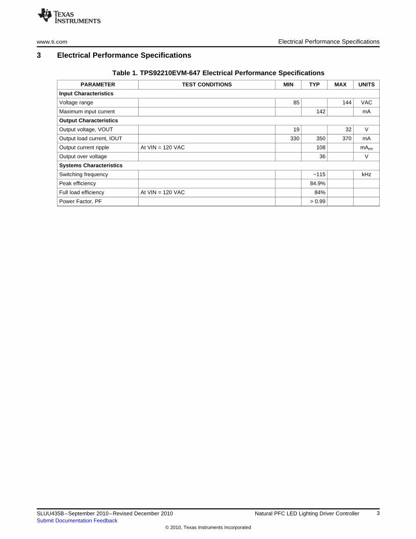
3 Electrical Performance Specifications
Table 1. TPS92210EVM-647 Electrical Performance Specifications
PARAMETER TEST CONDITIONS MIN TYP MAX UNITS
Input Characteristics
Voltage range 85 144 VAC
Maximum input current 142 mA
Output Characteristics
Output voltage, VOUT 19 32 V
Output load current, IOUT 330 350 370 mA
Output current ripple At VIN = 120 VAC 108 mAPP
Output over voltage 36 V
Systems Characteristics
Switching frequency ~115 kHz
Peak efficiency 84.9%
Full load efficiency At VIN = 120 VAC 84%
Power Factor, PF > 0.99
3SLUU435B–September 2010–Revised December 2010 Natural PFC LED Lighting Driver ControllerSubmit Documentation Feedback
© 2010, Texas Instruments Incorporated
+
+
+
Schematic www.ti.com
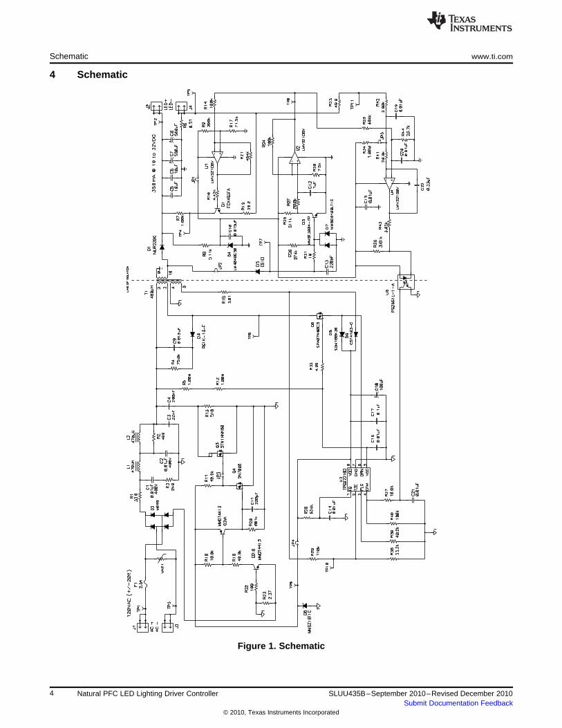
4 Schematic
Figure 1. Schematic
4 Natural PFC LED Lighting Driver Controller SLUU435B–September 2010–Revised December 2010Submit Documentation Feedback
© 2010, Texas Instruments Incorporated
AC Power
Supply
Ammeter
1
Volt meter 1
Ammeter
2
Voltmeter 2
Loop injection point
(TP8 and TP11)
www.ti.com Test Setup
5 Test Setup
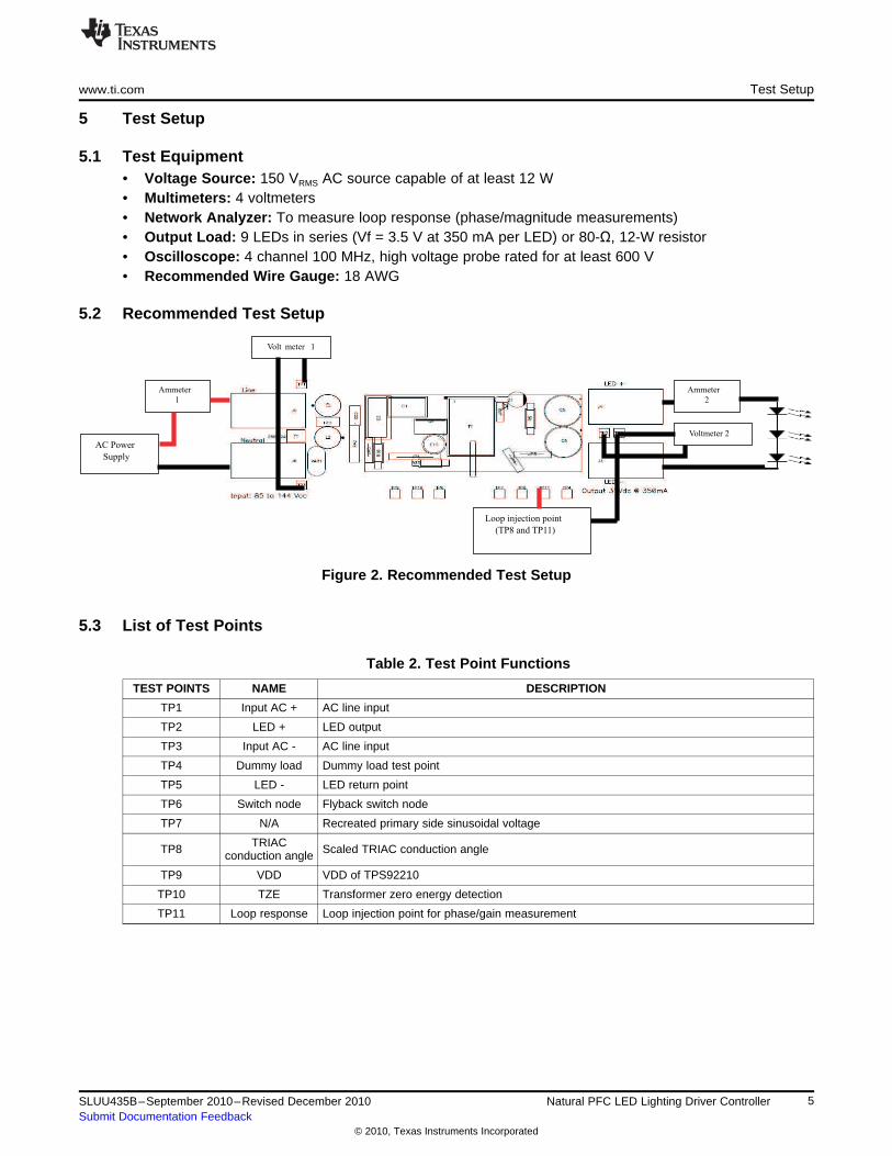
5.1 Test Equipment• Voltage Source: 150 VRMS AC source capable of at least 12 W• Multimeters: 4 voltmeters• Network Analyzer: To measure loop response (phase/magnitude measurements)• Output Load: 9 LEDs in series (Vf = 3.5 V at 350 mA per LED) or 80-Ω, 12-W resistor• Oscilloscope: 4 channel 100 MHz, high voltage probe rated for at least 600 V• Recommended Wire Gauge: 18 AWG
5.2 Recommended Test Setup
Figure 2. Recommended Test Setup
5.3 List of Test Points
Table 2. Test Point Functions
TEST POINTS NAME DESCRIPTION
TP1 Input AC + AC line input
TP2 LED + LED output
TP3 Input AC - AC line input
TP4 Dummy load Dummy load test point
TP5 LED - LED return point
TP6 Switch node Flyback switch node
TP7 N/A Recreated primary side sinusoidal voltage
TRIACTP8 Scaled TRIAC conduction angleconduction angle
TP9 VDD VDD of TPS92210
TP10 TZE Transformer zero energy detection
TP11 Loop response Loop injection point for phase/gain measurement
5SLUU435B–September 2010–Revised December 2010 Natural PFC LED Lighting Driver ControllerSubmit Documentation Feedback
© 2010, Texas Instruments Incorporated
Test Procedure www.ti.com
6 Test Procedure
CAUTION
High voltages exist on this EVM. Please handle with care. Do not touch EVMwhen powered.
An external load MUST be used to power up this EVM. No load on the output will trigger the over-voltageprotection and shut down the EVM.
6.1 Line Regulation and Efficiency Measurement Procedure1. Connect EVM per Figure 2 above. An external LED load must be used to start up the EVM. (A
frequency analyzer is not required for this procedure).2. Set AC source to 85 VRMS.3. Turn on AC source.4. Record output voltage reading from Voltmeter 2 and output current reading from Ammeter 2 and input
voltage reading from Voltmeter 1 and Ammeter 1.5. Increase output voltage by 5 VRMS.6. Repeat steps 4 and 5 until you reach 144 VRMS.7. Turn off the AC source.
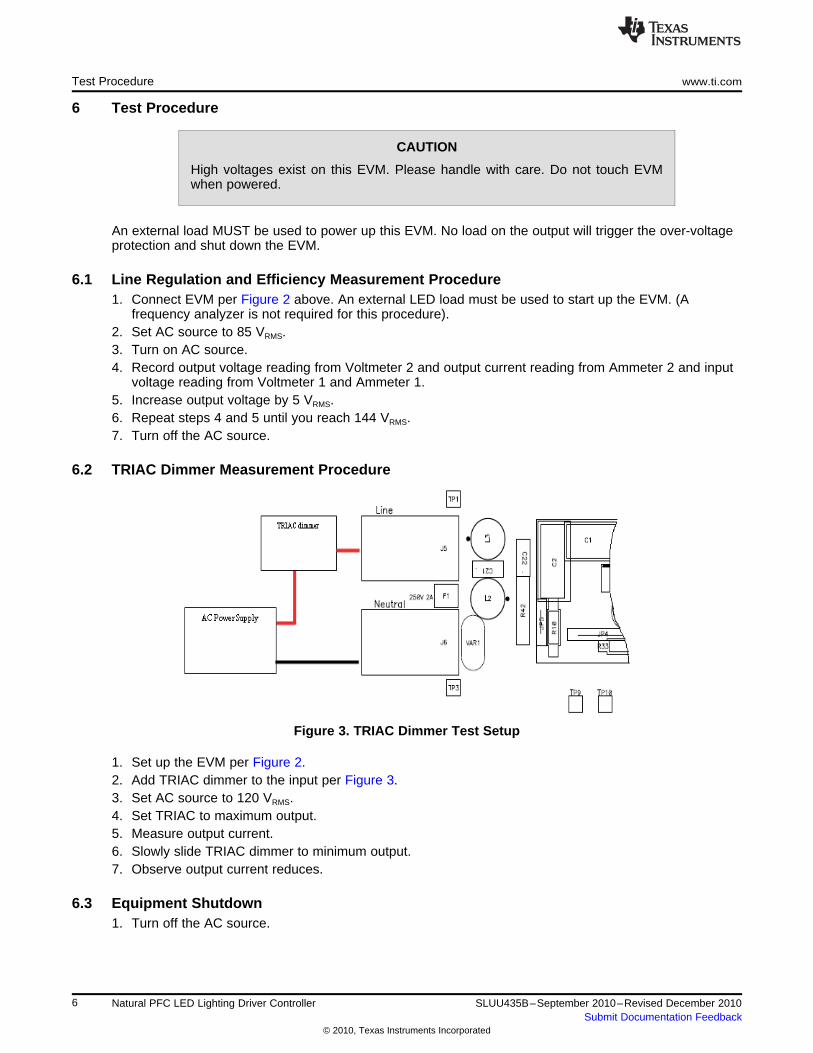
6.2 TRIAC Dimmer Measurement Procedure
Figure 3. TRIAC Dimmer Test Setup
1. Set up the EVM per Figure 2.2. Add TRIAC dimmer to the input per Figure 3.3. Set AC source to 120 VRMS.4. Set TRIAC to maximum output.5. Measure output current.6. Slowly slide TRIAC dimmer to minimum output.7. Observe output current reduces.
6.3 Equipment Shutdown1. Turn off the AC source.
6 Natural PFC LED Lighting Driver Controller SLUU435B–September 2010–Revised December 2010Submit Documentation Feedback
© 2010, Texas Instruments Incorporated
80 90 100 120 130 140 150
VAC
- Input Voltage - V
80.0
81.0
82.0
83.0
84.0
85.0
110
80.5
81.5
82.5
83.5
84.5h
-E
ffic
ien
cy
-%
EFFICIENCY
vs
INPUT VOLTAGE
70 80 90 110 120 130 140
VAC
- Input Voltage - V
340
342
344
346
348
350
100
I OU
T-
Ou
tp
ut
Cu
rre
nt
-m
A
OUTPUT CURRENT
vs
INPUT VOLTAGE
www.ti.com Performance Data and Typical Characteristic Curves
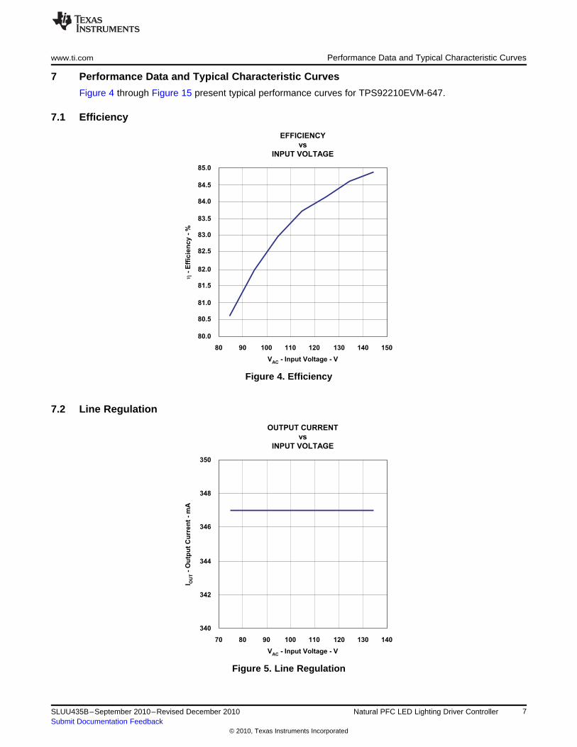
7 Performance Data and Typical Characteristic Curves
Figure 4 through Figure 15 present typical performance curves for TPS92210EVM-647.
7.1 Efficiency
Figure 4. Efficiency
7.2 Line Regulation
Figure 5. Line Regulation
7SLUU435B–September 2010–Revised December 2010 Natural PFC LED Lighting Driver ControllerSubmit Documentation Feedback
© 2010, Texas Instruments Incorporated
70 80 90 110 120 130 140
VAC
- Input Voltage - V
0.993
0.995
0.997
0.999
100
Po
we
rF
ac
to
r
POWER FACTOR
vs
INPUT VOLTAGE
18 20 22 26 28 30 32
VOUT
- Output Voltage - V
340
342
344
346
348
350
24
I OU
T-
Ou
tp
ut
Cu
rre
nt
-m
A
OUTPUT CURRENT
vs
OUTPUT VOLTAGE
Performance Data and Typical Characteristic Curves www.ti.com
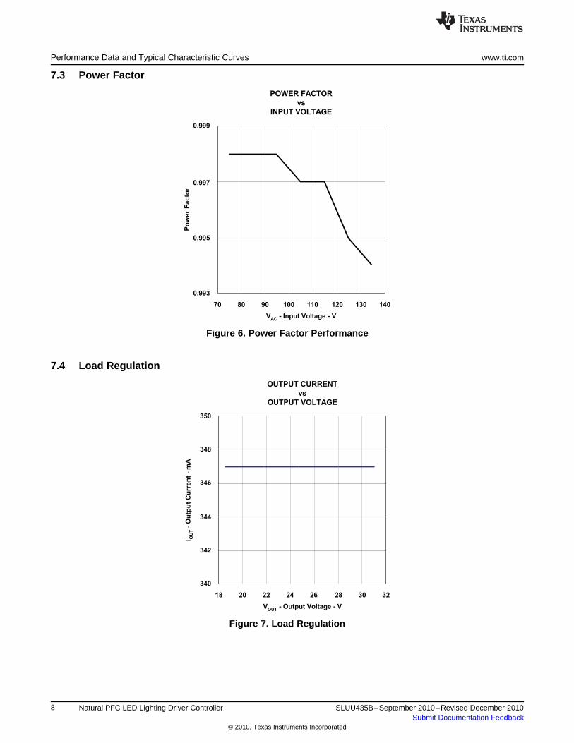
7.3 Power Factor
Figure 6. Power Factor Performance
7.4 Load Regulation
Figure 7. Load Regulation
8 Natural PFC LED Lighting Driver Controller SLUU435B–September 2010–Revised December 2010Submit Documentation Feedback
© 2010, Texas Instruments Incorporated
1 10
f - Frequency - Hz
-100
80
100
-40
20
Ga
in-d
B
GAIN/PHASE
vs
FREQUENCY
100
-80
0
40
-200
150
200
-100
50
Ph
as
eM
arg
in-
de
gre
es
-150
-50
100
-20
0
Gain
Phase
60
-60
50 70 110 130 150
Turn-On Angle - degrees
0
50
100
150
200
250
90
I OU
T-
Ou
tp
ut
Cu
rre
nt
-m
A
OUTPUT CURRENT
vs
TURN-ON ANGLE
www.ti.com Performance Data and Typical Characteristic Curves
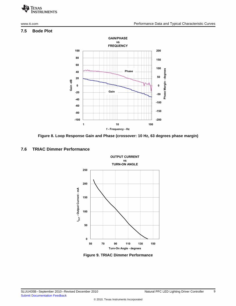
7.5 Bode Plot
Figure 8. Loop Response Gain and Phase (crossover: 10 Hz, 63 degrees phase margin)
7.6 TRIAC Dimmer Performance
Figure 9. TRIAC Dimmer Performance
9SLUU435B–September 2010–Revised December 2010 Natural PFC LED Lighting Driver ControllerSubmit Documentation Feedback
© 2010, Texas Instruments Incorporated
Performance Data and Typical Characteristic Curves www.ti.com
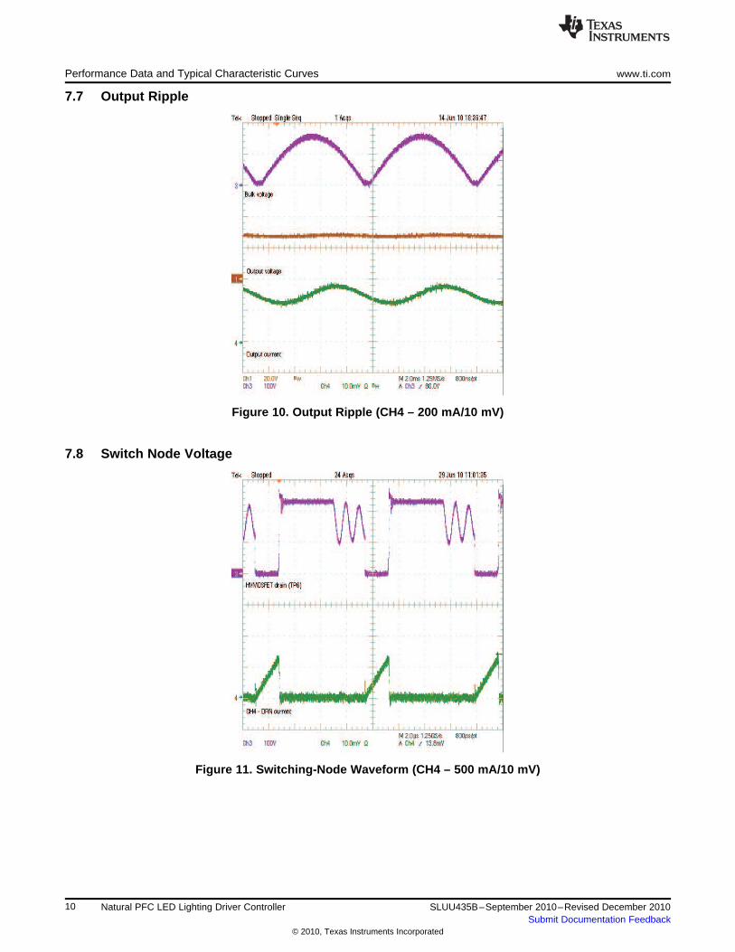
7.7 Output Ripple
Figure 10. Output Ripple (CH4 – 200 mA/10 mV)
7.8 Switch Node Voltage
Figure 11. Switching-Node Waveform (CH4 – 500 mA/10 mV)
10 Natural PFC LED Lighting Driver Controller SLUU435B–September 2010–Revised December 2010Submit Documentation Feedback
© 2010, Texas Instruments Incorporated
www.ti.com Performance Data and Typical Characteristic Curves
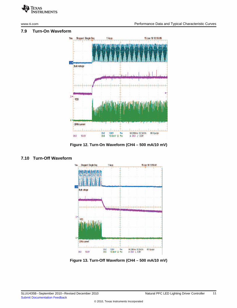
7.9 Turn-On Waveform
Figure 12. Turn-On Waveform (CH4 – 500 mA/10 mV)
7.10 Turn-Off Waveform
Figure 13. Turn-Off Waveform (CH4 – 500 mA/10 mV)
11SLUU435B–September 2010–Revised December 2010 Natural PFC LED Lighting Driver ControllerSubmit Documentation Feedback
© 2010, Texas Instruments Incorporated
Performance Data and Typical Characteristic Curves www.ti.com
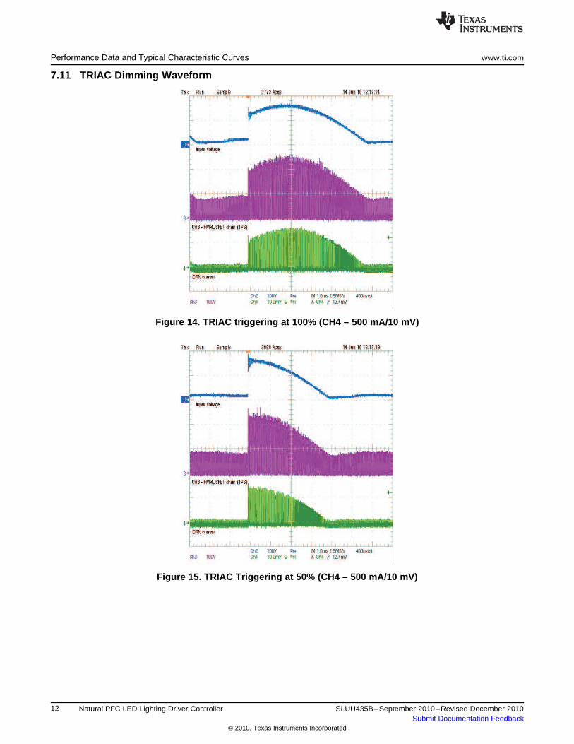
7.11 TRIAC Dimming Waveform
Figure 14. TRIAC triggering at 100% (CH4 – 500 mA/10 mV)
Figure 15. TRIAC Triggering at 50% (CH4 – 500 mA/10 mV)
12 Natural PFC LED Lighting Driver Controller SLUU435B–September 2010–Revised December 2010Submit Documentation Feedback
© 2010, Texas Instruments Incorporated
www.ti.com EVM Assembly Drawing and PCB Layout
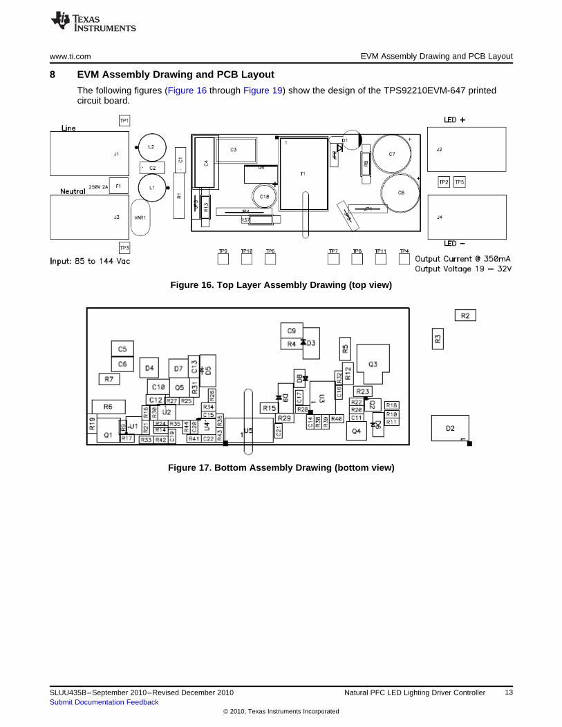
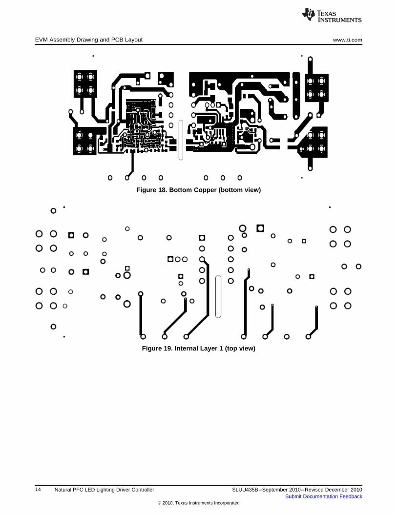
8 EVM Assembly Drawing and PCB Layout
The following figures (Figure 16 through Figure 19) show the design of the TPS92210EVM-647 printedcircuit board.
Figure 16. Top Layer Assembly Drawing (top view)
Figure 17. Bottom Assembly Drawing (bottom view)
13SLUU435B–September 2010–Revised December 2010 Natural PFC LED Lighting Driver ControllerSubmit Documentation Feedback
© 2010, Texas Instruments Incorporated
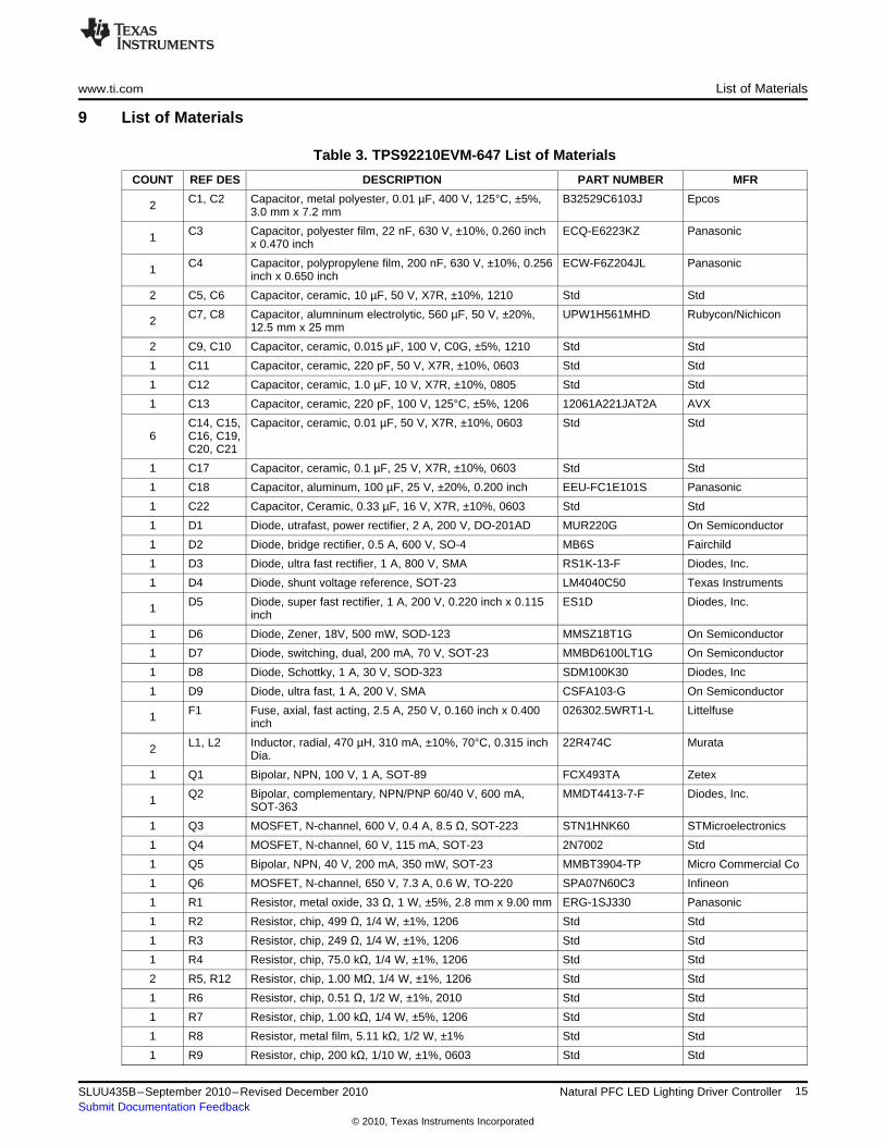
EVM Assembly Drawing and PCB Layout www.ti.com
Figure 18. Bottom Copper (bottom view)
Figure 19. Internal Layer 1 (top view)
14 Natural PFC LED Lighting Driver Controller SLUU435B–September 2010–Revised December 2010Submit Documentation Feedback
© 2010, Texas Instruments Incorporated
www.ti.com List of Materials
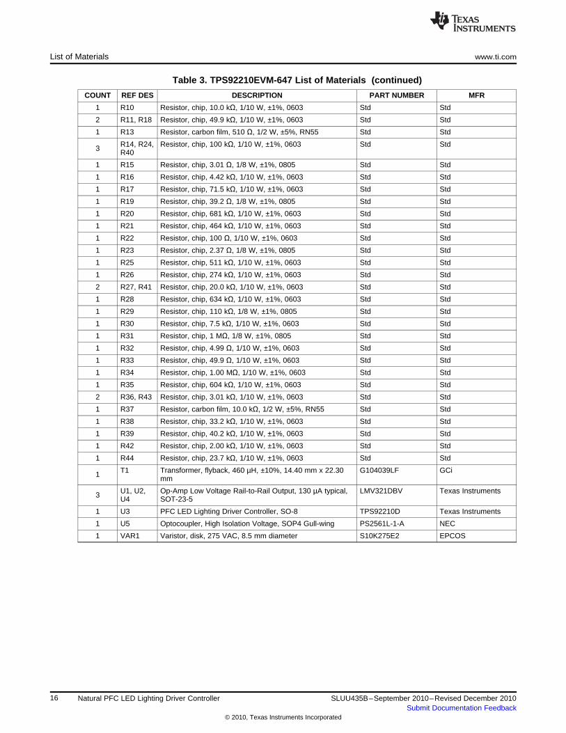
9 List of Materials
Table 3. TPS92210EVM-647 List of Materials
COUNT REF DES DESCRIPTION PART NUMBER MFR
C1, C2 Capacitor, metal polyester, 0.01 µF, 400 V, 125°C, ±5%, B32529C6103J Epcos2 3.0 mm x 7.2 mm
C3 Capacitor, polyester film, 22 nF, 630 V, ±10%, 0.260 inch ECQ-E6223KZ Panasonic1 x 0.470 inch
C4 Capacitor, polypropylene film, 200 nF, 630 V, ±10%, 0.256 ECW-F6Z204JL Panasonic1 inch x 0.650 inch
2 C5, C6 Capacitor, ceramic, 10 µF, 50 V, X7R, ±10%, 1210 Std Std
C7, C8 Capacitor, alumninum electrolytic, 560 µF, 50 V, ±20%, UPW1H561MHD Rubycon/Nichicon2 12.5 mm x 25 mm
2 C9, C10 Capacitor, ceramic, 0.015 µF, 100 V, C0G, ±5%, 1210 Std Std
1 C11 Capacitor, ceramic, 220 pF, 50 V, X7R, ±10%, 0603 Std Std
1 C12 Capacitor, ceramic, 1.0 µF, 10 V, X7R, ±10%, 0805 Std Std
1 C13 Capacitor, ceramic, 220 pF, 100 V, 125°C, ±5%, 1206 12061A221JAT2A AVX
C14, C15, Capacitor, ceramic, 0.01 µF, 50 V, X7R, ±10%, 0603 Std Std6 C16, C19,
C20, C21
1 C17 Capacitor, ceramic, 0.1 µF, 25 V, X7R, ±10%, 0603 Std Std
1 C18 Capacitor, aluminum, 100 µF, 25 V, ±20%, 0.200 inch EEU-FC1E101S Panasonic
1 C22 Capacitor, Ceramic, 0.33 µF, 16 V, X7R, ±10%, 0603 Std Std
1 D1 Diode, utrafast, power rectifier, 2 A, 200 V, DO-201AD MUR220G On Semiconductor
1 D2 Diode, bridge rectifier, 0.5 A, 600 V, SO-4 MB6S Fairchild
1 D3 Diode, ultra fast rectifier, 1 A, 800 V, SMA RS1K-13-F Diodes, Inc.
1 D4 Diode, shunt voltage reference, SOT-23 LM4040C50 Texas Instruments
D5 Diode, super fast rectifier, 1 A, 200 V, 0.220 inch x 0.115 ES1D Diodes, Inc.1 inch
1 D6 Diode, Zener, 18V, 500 mW, SOD-123 MMSZ18T1G On Semiconductor
1 D7 Diode, switching, dual, 200 mA, 70 V, SOT-23 MMBD6100LT1G On Semiconductor
1 D8 Diode, Schottky, 1 A, 30 V, SOD-323 SDM100K30 Diodes, Inc
1 D9 Diode, ultra fast, 1 A, 200 V, SMA CSFA103-G On Semiconductor
F1 Fuse, axial, fast acting, 2.5 A, 250 V, 0.160 inch x 0.400 026302.5WRT1-L Littelfuse1 inch
L1, L2 Inductor, radial, 470 µH, 310 mA, ±10%, 70°C, 0.315 inch 22R474C Murata2 Dia.
1 Q1 Bipolar, NPN, 100 V, 1 A, SOT-89 FCX493TA Zetex
Q2 Bipolar, complementary, NPN/PNP 60/40 V, 600 mA, MMDT4413-7-F Diodes, Inc.1 SOT-363
1 Q3 MOSFET, N-channel, 600 V, 0.4 A, 8.5 Ω, SOT-223 STN1HNK60 STMicroelectronics
1 Q4 MOSFET, N-channel, 60 V, 115 mA, SOT-23 2N7002 Std
1 Q5 Bipolar, NPN, 40 V, 200 mA, 350 mW, SOT-23 MMBT3904-TP Micro Commercial Co
1 Q6 MOSFET, N-channel, 650 V, 7.3 A, 0.6 W, TO-220 SPA07N60C3 Infineon
1 R1 Resistor, metal oxide, 33 Ω, 1 W, ±5%, 2.8 mm x 9.00 mm ERG-1SJ330 Panasonic
1 R2 Resistor, chip, 499 Ω, 1/4 W, ±1%, 1206 Std Std
1 R3 Resistor, chip, 249 Ω, 1/4 W, ±1%, 1206 Std Std
1 R4 Resistor, chip, 75.0 kΩ, 1/4 W, ±1%, 1206 Std Std
2 R5, R12 Resistor, chip, 1.00 MΩ, 1/4 W, ±1%, 1206 Std Std
1 R6 Resistor, chip, 0.51 Ω, 1/2 W, ±1%, 2010 Std Std
1 R7 Resistor, chip, 1.00 kΩ, 1/4 W, ±5%, 1206 Std Std
1 R8 Resistor, metal film, 5.11 kΩ, 1/2 W, ±1% Std Std
1 R9 Resistor, chip, 200 kΩ, 1/10 W, ±1%, 0603 Std Std
15SLUU435B–September 2010–Revised December 2010 Natural PFC LED Lighting Driver ControllerSubmit Documentation Feedback
© 2010, Texas Instruments Incorporated
List of Materials www.ti.com
Table 3. TPS92210EVM-647 List of Materials (continued)
COUNT REF DES DESCRIPTION PART NUMBER MFR
1 R10 Resistor, chip, 10.0 kΩ, 1/10 W, ±1%, 0603 Std Std
2 R11, R18 Resistor, chip, 49.9 kΩ, 1/10 W, ±1%, 0603 Std Std
1 R13 Resistor, carbon film, 510 Ω, 1/2 W, ±5%, RN55 Std Std
R14, R24, Resistor, chip, 100 kΩ, 1/10 W, ±1%, 0603 Std Std3 R40
1 R15 Resistor, chip, 3.01 Ω, 1/8 W, ±1%, 0805 Std Std
1 R16 Resistor, chip, 4.42 kΩ, 1/10 W, ±1%, 0603 Std Std
1 R17 Resistor, chip, 71.5 kΩ, 1/10 W, ±1%, 0603 Std Std
1 R19 Resistor, chip, 39.2 Ω, 1/8 W, ±1%, 0805 Std Std
1 R20 Resistor, chip, 681 kΩ, 1/10 W, ±1%, 0603 Std Std
1 R21 Resistor, chip, 464 kΩ, 1/10 W, ±1%, 0603 Std Std
1 R22 Resistor, chip, 100 Ω, 1/10 W, ±1%, 0603 Std Std
1 R23 Resistor, chip, 2.37 Ω, 1/8 W, ±1%, 0805 Std Std
1 R25 Resistor, chip, 511 kΩ, 1/10 W, ±1%, 0603 Std Std
1 R26 Resistor, chip, 274 kΩ, 1/10 W, ±1%, 0603 Std Std
2 R27, R41 Resistor, chip, 20.0 kΩ, 1/10 W, ±1%, 0603 Std Std
1 R28 Resistor, chip, 634 kΩ, 1/10 W, ±1%, 0603 Std Std
1 R29 Resistor, chip, 110 kΩ, 1/8 W, ±1%, 0805 Std Std
1 R30 Resistor, chip, 7.5 kΩ, 1/10 W, ±1%, 0603 Std Std
1 R31 Resistor, chip, 1 MΩ, 1/8 W, ±1%, 0805 Std Std
1 R32 Resistor, chip, 4.99 Ω, 1/10 W, ±1%, 0603 Std Std
1 R33 Resistor, chip, 49.9 Ω, 1/10 W, ±1%, 0603 Std Std
1 R34 Resistor, chip, 1.00 MΩ, 1/10 W, ±1%, 0603 Std Std
1 R35 Resistor, chip, 604 kΩ, 1/10 W, ±1%, 0603 Std Std
2 R36, R43 Resistor, chip, 3.01 kΩ, 1/10 W, ±1%, 0603 Std Std
1 R37 Resistor, carbon film, 10.0 kΩ, 1/2 W, ±5%, RN55 Std Std
1 R38 Resistor, chip, 33.2 kΩ, 1/10 W, ±1%, 0603 Std Std
1 R39 Resistor, chip, 40.2 kΩ, 1/10 W, ±1%, 0603 Std Std
1 R42 Resistor, chip, 2.00 kΩ, 1/10 W, ±1%, 0603 Std Std
1 R44 Resistor, chip, 23.7 kΩ, 1/10 W, ±1%, 0603 Std Std
T1 Transformer, flyback, 460 µH, ±10%, 14.40 mm x 22.30 G104039LF GCi1 mm
U1, U2, Op-Amp Low Voltage Rail-to-Rail Output, 130 µA typical, LMV321DBV Texas Instruments3 U4 SOT-23-5
1 U3 PFC LED Lighting Driver Controller, SO-8 TPS92210D Texas Instruments
1 U5 Optocoupler, High Isolation Voltage, SOP4 Gull-wing PS2561L-1-A NEC
1 VAR1 Varistor, disk, 275 VAC, 8.5 mm diameter S10K275E2 EPCOS
16 Natural PFC LED Lighting Driver Controller SLUU435B–September 2010–Revised December 2010Submit Documentation Feedback
© 2010, Texas Instruments Incorporated
Evaluation Board/Kit Important Notice
Texas Instruments (TI) provides the enclosed product(s) under the following conditions:
This evaluation board/kit is intended for use for ENGINEERING DEVELOPMENT, DEMONSTRATION, OR EVALUATIONPURPOSES ONLY and is not considered by TI to be a finished end-product fit for general consumer use. Persons handling theproduct(s) must have electronics training and observe good engineering practice standards. As such, the goods being provided arenot intended to be complete in terms of required design-, marketing-, and/or manufacturing-related protective considerations,including product safety and environmental measures typically found in end products that incorporate such semiconductorcomponents or circuit boards. This evaluation board/kit does not fall within the scope of the European Union directives regardingelectromagnetic compatibility, restricted substances (RoHS), recycling (WEEE), FCC, CE or UL, and therefore may not meet thetechnical requirements of these directives or other related directives.
Should this evaluation board/kit not meet the specifications indicated in the User’s Guide, the board/kit may be returned within 30days from the date of delivery for a full refund. THE FOREGOING WARRANTY IS THE EXCLUSIVE WARRANTY MADE BYSELLER TO BUYER AND IS IN LIEU OF ALL OTHER WARRANTIES, EXPRESSED, IMPLIED, OR STATUTORY, INCLUDINGANY WARRANTY OF MERCHANTABILITY OR FITNESS FOR ANY PARTICULAR PURPOSE.
The user assumes all responsibility and liability for proper and safe handling of the goods. Further, the user indemnifies TI from allclaims arising from the handling or use of the goods. Due to the open construction of the product, it is the user’s responsibility totake any and all appropriate precautions with regard to electrostatic discharge.
EXCEPT TO THE EXTENT OF THE INDEMNITY SET FORTH ABOVE, NEITHER PARTY SHALL BE LIABLE TO THE OTHERFOR ANY INDIRECT, SPECIAL, INCIDENTAL, OR CONSEQUENTIAL DAMAGES.
TI currently deals with a variety of customers for products, and therefore our arrangement with the user is not exclusive.
TI assumes no liability for applications assistance, customer product design, software performance, or infringement ofpatents or services described herein.
Please read the User’s Guide and, specifically, the Warnings and Restrictions notice in the User’s Guide prior to handling theproduct. This notice contains important safety information about temperatures and voltages. For additional information on TI’senvironmental and/or safety programs, please contact the TI application engineer or visit www.ti.com/esh.
No license is granted under any patent right or other intellectual property right of TI covering or relating to any machine, process, orcombination in which such TI products or services might be or are used.
FCC Warning
This evaluation board/kit is intended for use for ENGINEERING DEVELOPMENT, DEMONSTRATION, OR EVALUATIONPURPOSES ONLY and is not considered by TI to be a finished end-product fit for general consumer use. It generates, uses, andcan radiate radio frequency energy and has not been tested for compliance with the limits of computing devices pursuant to part 15of FCC rules, which are designed to provide reasonable protection against radio frequency interference. Operation of thisequipment in other environments may cause interference with radio communications, in which case the user at his own expensewill be required to take whatever measures may be required to correct this interference.
EVM Warnings and Restrictions
It is important to operate this EVM within the input voltage range of 85 V to 144 V and the output voltage range of 19 V to 32 V .
Exceeding the specified input range may cause unexpected operation and/or irreversible damage to the EVM. If there arequestions concerning the input range, please contact a TI field representative prior to connecting the input power.
Applying loads outside of the specified output range may result in unintended operation and/or possible permanent damage to theEVM. Please consult the EVM User's Guide prior to connecting any load to the EVM output. If there is uncertainty as to the loadspecification, please contact a TI field representative.
During normal operation, some circuit components may have case temperatures greater than 50° C. The EVM is designed tooperate properly with certain components above 50° C as long as the input and output ranges are maintained. These componentsinclude but are not limited to linear regulators, switching transistors, pass transistors, and current sense resistors. These types ofdevices can be identified using the EVM schematic located in the EVM User's Guide. When placing measurement probes nearthese devices during operation, please be aware that these devices may be very warm to the touch.
Mailing Address: Texas Instruments, Post Office Box 655303, Dallas, Texas 75265Copyright © 2010, Texas Instruments Incorporated
IMPORTANT NOTICE
Texas Instruments Incorporated and its subsidiaries (TI) reserve the right to make corrections, modifications, enhancements, improvements,and other changes to its products and services at any time and to discontinue any product or service without notice. Customers shouldobtain the latest relevant information before placing orders and should verify that such information is current and complete. All products aresold subject to TI’s terms and conditions of sale supplied at the time of order acknowledgment.
TI warrants performance of its hardware products to the specifications applicable at the time of sale in accordance with TI’s standardwarranty. Testing and other quality control techniques are used to the extent TI deems necessary to support this warranty. Except wheremandated by government requirements, testing of all parameters of each product is not necessarily performed.
TI assumes no liability for applications assistance or customer product design. Customers are responsible for their products andapplications using TI components. To minimize the risks associated with customer products and applications, customers should provideadequate design and operating safeguards.
TI does not warrant or represent that any license, either express or implied, is granted under any TI patent right, copyright, mask work right,or other TI intellectual property right relating to any combination, machine, or process in which TI products or services are used. Informationpublished by TI regarding third-party products or services does not constitute a license from TI to use such products or services or awarranty or endorsement thereof. Use of such information may require a license from a third party under the patents or other intellectualproperty of the third party, or a license from TI under the patents or other intellectual property of TI.
Reproduction of TI information in TI data books or data sheets is permissible only if reproduction is without alteration and is accompaniedby all associated warranties, conditions, limitations, and notices. Reproduction of this information with alteration is an unfair and deceptivebusiness practice. TI is not responsible or liable for such altered documentation. Information of third parties may be subject to additionalrestrictions.
Resale of TI products or services with statements different from or beyond the parameters stated by TI for that product or service voids allexpress and any implied warranties for the associated TI product or service and is an unfair and deceptive business practice. TI is notresponsible or liable for any such statements.
TI products are not authorized for use in safety-critical applications (such as life support) where a failure of the TI product would reasonablybe expected to cause severe personal injury or death, unless officers of the parties have executed an agreement specifically governingsuch use. Buyers represent that they have all necessary expertise in the safety and regulatory ramifications of their applications, andacknowledge and agree that they are solely responsible for all legal, regulatory and safety-related requirements concerning their productsand any use of TI products in such safety-critical applications, notwithstanding any applications-related information or support that may beprovided by TI. Further, Buyers must fully indemnify TI and its representatives against any damages arising out of the use of TI products insuch safety-critical applications.
TI products are neither designed nor intended for use in military/aerospace applications or environments unless the TI products arespecifically designated by TI as military-grade or "enhanced plastic." Only products designated by TI as military-grade meet militaryspecifications. Buyers acknowledge and agree that any such use of TI products which TI has not designated as military-grade is solely atthe Buyer's risk, and that they are solely responsible for compliance with all legal and regulatory requirements in connection with such use.
TI products are neither designed nor intended for use in automotive applications or environments unless the specific TI products aredesignated by TI as compliant with ISO/TS 16949 requirements. Buyers acknowledge and agree that, if they use any non-designatedproducts in automotive applications, TI will not be responsible for any failure to meet such requirements.
Following are URLs where you can obtain information on other Texas Instruments products and application solutions:
Products Applications
Amplifiers amplifier.ti.com Audio www.ti.com/audio
Data Converters dataconverter.ti.com Automotive www.ti.com/automotive
DLP® Products www.dlp.com Communications and www.ti.com/communicationsTelecom
DSP dsp.ti.com Computers and www.ti.com/computersPeripherals
Clocks and Timers www.ti.com/clocks Consumer Electronics www.ti.com/consumer-apps
Interface interface.ti.com Energy www.ti.com/energy
Logic logic.ti.com Industrial www.ti.com/industrial
Power Mgmt power.ti.com Medical www.ti.com/medical
Microcontrollers microcontroller.ti.com Security www.ti.com/security
RFID www.ti-rfid.com Space, Avionics & www.ti.com/space-avionics-defenseDefense
RF/IF and ZigBee® Solutions www.ti.com/lprf Video and Imaging www.ti.com/video
Wireless www.ti.com/wireless-apps
Mailing Address: Texas Instruments, Post Office Box 655303, Dallas, Texas 75265Copyright © 2010, Texas Instruments Incorporated