using saoimage ds9 - ciao 3 - chandra x-ray...
TRANSCRIPT

Using SAOImage ds9
CIAO 3.4 Science Threads
Using SAOImage ds9 − CIAO 3.4
Using SAOImage ds9 1

Table of ContentsGetting Started
ds9 and XPA Versions♦ Using a newer version of ds9♦
•
Coordinate Definitions: Image, Physical/Sky, Celestial, and WCS• Command Line Arguments and Preferences• Displaying an Event File in Different Coordinates• Using Multiple Frames• The Analysis Menu
Contours and the DSSA. Locking CrosshairsB. Using Analysis ScriptsC.
•
XPA: Public Access to Data and Algorithms• History• Images
Image in (x,y) binned by 16♦ Image in (detx,dety) binned by 4♦ Using multiple frames♦ X−ray image with contours♦ X−ray and optical images with contours♦ Images with contours and locked crosshairs♦
•
Using SAOImage ds9 − CIAO 3.4
2 Table of Contents

URL: http://cxc.harvard.edu/ciao/threads/ds9/ Last modified: 9 Jan 2007
Using SAOImage ds9CIAO 3.4 Science Threads
Overview
Last Update: 9 Jan 2007 − created Using a newer version of ds9 subsection
Synopsis:
The imaging application SAOImage ds9 is distributed with CIAO as the default imager. Developedindependently of the software, ds9 contains some CIAO−specific support.
In CIAO 3.3, basic support was added for version 4 of the ds9 region files, which have a slightly differentformat than the version 3 files. Users working with more complicated files, such as "composite" regions, mayencounter problems. Refer to the Libraries: regionlib section of the CIAO 3.3 release notes for a comparisonof the two formats.
Purpose:
To introduce a few of the key features used in CIAO analysis ranging from simple (e.g. defining preferences)to complex (e.g. use of the XPA messaging system).
Read this thread if:
you would like to learn to display and work interactively with ACIS and HRC imaging and grating eventfiles.
Related Links:
ds9 Reference Manual• Chandra Coordinate Systems: Imaging document (PS, 25pp)• Using CIAO Region Files thread•
Proceed to the HTML or hardcopy (PDF: A4 | letter) version of the thread.
Getting Started
Sample ObsID used: 1712 (ACIS−S, 3C 273)
File types needed: evt2; asol1
The preferences set in ds9 are stored in a file called $HOME/.ds9.prf (see the section on Command LineArguments and Preferences). It is possible that a .ds9.prf file created for a different version of ds9 maycause problems with the ds9 packaged in CIAO. To avoid a possible conflict, delete or rename this file before
Using SAOImage ds9 − CIAO 3.4
Using SAOImage ds9 3

using ds9 in CIAO.
ds9 and XPA Versions
Since ds9 and XPA can both be used independently of CIAO, it is possible that your local system has adifferent version of installed than the one that is packaged with CIAO. Also, in order to run CIAO scriptsfrom ds9, the imager must have been launched from a term window already running CIAO. For these reasons,we recommend that you make sure CIAO is running in the current window before beginning any analysis taskusing ds9 or XPA. Otherwise, incompatibilities between the imager and the commands in the thread mayarise.
Here we show that the ds9 accessed from the term window changes after starting CIAO:
unix% which ds9/opt/local/bin/ds9
unix% ciaoCIAO configuration is complete... CIAO version : CIAO 3.4 Sunday, November 19, 2006 Proposal Toolkit version : Cycle 9 Sunday, November 19, 2006 bin dir : /soft/ciao/bin
unix% which ds9/soft/ciao/ots/saord/ds9
The same applies to XPA:
unix% which xpaget/opt/local/bin/xpaget
unix% ciaoCIAO configuration is complete... CIAO version : CIAO 3.4 Sunday, November 19, 2006 Proposal Toolkit version : Cycle 9 Sunday, November 19, 2006 bin dir : /soft/ciao/bin
unix% which xpaget/soft/ciao/bin/xpaget
Any CIAO thread that refers to ds9 and/or XPA assumes that the version being used is the one packaged withCIAO: ds9 v4.0b7 and XPA v2.1.4 for CIAO 3.4.
Using a newer version of ds9
When a CIAO release is being prepared, the most recent version of ds9 available is used in testing and thenpackaged with the software. Since updates to ds9 are released on a much shorter timescale than CIAO, usersmay wish to upgrade independently of CIAO to take advantage of new features and bug fixes.
If you wish to use a different version of ds9 than the one packaged with CIAO, please refer to this FAQ. It isnot guaranteed that CIAO will work flawlessly with a newer release of ds9! It is possible that changes to theimager may cause unexpected problems in the CIAO software.
Known Issues
In CIAO 3.4, the Prism and ObsVis GUIs will not image data if a newer version of ds9 is in the imager path.
Using SAOImage ds9 − CIAO 3.4
4 ds9 and XPA Versions

Coordinate Definitions: Image, Physical/Sky, Celestial, andWCS
There are a few terms needed to discuss coordinate systems:
Image: image coordinates specify a location in an image. The lower, left pixel of the array will havethe image coordinates (1,1). Coordinates increase to the right in x and up in y. Note that the lower leftcorner of the array will have coordinates (0.5,0.5).
•
Physical/Sky: "sky" is shorthand for (x,y) coordinates, the system used most commonly in Chandradata analysis. Physical coordinates are the generalized system used by ds9. The sky coordinates of anevent are defined as the point where an event crosses the imaginary tangent plane for a given pointingof the telescope's mirrors. This is calculated (by the CIAO tools reproject_events andacis_process_events / hrc_process_events) from knowledge of the location of theevent on the detector, the location of the detector in the observatory, and the pointing of the telescope.For Chandra data, the range of sky coordinates is 0.5:8192.5 for ACIS, 0.5:32768.5 forHRC−I, and 0.5:65536.5 for HRC−S.
When saving regions in ds9, use "Ciao" formatted regions to ensure total compatibility with theCIAO tools. "Ciao" format regions are saved in physical coordinates by default. The CIAO and ds9region formats section of the Using CIAO Regions thread has a discussion on the ASCII region typesavailable for use. If necessary, it is possible to convert region formats/coordinate systems by loadingone type (e.g. ds9 format in celestial coordinates) and saving it in a different format/coordinate system(e.g. CIAO format in physical coordinates).
•
Celestial: the celestial coordinate system is the standard method of measuring positions in the sky.The transformations from sky (x,y) to celestial (RA, Dec) are described at the end of the event file"columns" listing:
unix% dmlist acisf01712N002_evt2.fits cols...cut...
8: EQPOS(RA ) = (+187.2761) +TAN[(−0.000136667)* (sky(x)−(+4096.50))] (DEC) (+2.0539 ) (+0.000136667) ( (y) (+4096.50))
The two systems are related by the aimpoint of the observation. When events are projected onto thecelestial sphere, RA increases to the left (hence the minus sign in the definition) and Dec increasesupward. In this example, the celestial coordinates of the reference pixel in degrees (J2000) are(187.2761,2.0539).
Although CIAO regions may be saved in celestial coordinates, only sexagesimal coordinates arecurrently supported (e.g. circle(17:46:14.065,−28:51:39,1.0')). Since some tools arenot yet able to transform from celestial to sky coordinates, we recommend using the physical format.
•
WCS: the World Coordinate System (WCS) is a generalized name for the celestial coordinate system.The default celestial coordinate system in CIAO and ds9 is the J2000 system. A complete descriptionof the WCS standard is given on the WCSTools home page.
As described above, the (x,y) coordinate system is related to the celestial coordinate system byspecifying the (RA, Dec) of a reference pixel in the file's header. It is sometimes necessary to editthese header keywords to improve upon Chandra's pointing accuracy. For more information, see theAspect caveats and the Improving the Astrometry of your Data: Correct for a Known ProcessingOffset thread.
•
For a detailed discussion of the relationships between Chandra instrument coordinate systems, see theChandra Coordinate Systems: Imaging document (PS, 25pp).
Using SAOImage ds9 − CIAO 3.4
Coordinate Definitions: Image, Physical/Sky, Celestial, and WCS 5

Command Line Arguments and Preferences
Command line arguments may be used to perform a task when opening the application. For example, tospecify log scaling when loading an event file:
unix% ds9 acisf01712N002_evt2.fits −log
A more involved example overlays a region onto the file, sends the image to the printer, and then closes ds9:
unix% ds9 acisf01712N002_evt2.fits −region sources.reg −print −exit
A short list of the available command line arguments can be found by typing "ds9 −−help" in a termwindow. Detailed descriptions of the arguments are available from the Command Line Options section of theds9 manual.
Preferences are user−defined default settings accessed from the "Edit −> Preferences" menu. Dozens ofsettings are available for modification, such as:
color scale• display buffer size• window layout• region shape• analysis file (see the Using Analysis Scripts section)•
Most of the options are self−explanatory, but there is more information on each in the Preferences section ofthe ds9 manual. Note that under the "Information Panel" is an option to display "Detector" coordinates. Thisdoes not refer to the Chandra detector coordinates (i.e. det or tdet).
If these settings are changed and "Save Preferences" is chosen, the preferences are written to/home/username/.ds9.prf. The next time ds9 is started, this file is read and the preferences are used.
Important: as mentioned before, the preference files are generally not backward−compatible. This means a.ds9.prf created by a newer version of ds9 may react badly with the ds9 packaged in CIAO. Pleasereference the Preferences section of the ds9 manual for information on avoiding this problem when supportingmultiple versions of ds9.
Displaying an Event File in Different Coordinates
The most direct way of checking quality and content of an event file is to view it in ds9:
unix% ds9 acisf01712N002_evt2.fits &
The imager will display a 1k x 1k array of pixels by default (this may be changed in the preferences). Thetypical Chandra image will need to be binned to see the entire field of view. Using the "Bin" button or menu,try a binning factor of 16. If the Scale is also set to "Log", the image should look like Figure 1 .
ds9 also has the ability to display any of the other columns stored in the event file, although it is onlymeaningful to use one of the spatial vector columns. In order to display the file in other coordinates, use the"Bin −> Binning Parameters" menu to select the two columns to display. To create an image in detectorcoordinates (detx,dety), select them from the "Bin Columns" menus. Change "Bin Factor" to 4, select the "orcenter of data" button, and click "Apply". Figure 2 shows the results.
Using SAOImage ds9 − CIAO 3.4
6 Command Line Arguments and Preferences
Displaying the event file in detector coordinates reveals details about how the observation was done. Badcolumns (removed in the level=2 event file, so not visible here) are displayed as dark lines and point sourcesappear as limb−brightened squares due to the telescope dither. This demonstrates the value of dithering thetelescope; instrumental artifacts are blurred, providing more regular coverage across the field.
Alternatively, one can display an event file in specific coordinates when calling ds9 from the command line.The syntax is similar to the CIAO binning syntax:
unix% ds9 "acisf01712N002_evt2.fits[bin=detx,dety]" &
The file is loaded into ds9 and displayed in detector coordinates.
Using Multiple Frames
ds9 allows the simultaneous viewing of multiple images through the use of frames, which are memory areasused to store images for viewing.
There are two ways to create multiple frames:
Specify all the filenames when starting ds9:
unix% ds9 acisf01712N002_evt2.fits −cmap b −log ../../315/primary/acisf00315N002_evt2.fits \ −cmap b −log /data/1838/primary/acisf01838N001_evt2.fits −cmap b −log &
Notice that the pathnames may be relative or absolute. Issuing this command created Figure 3 .
1.
Use the "Frame −> New Frame" menu option. This process can be repeated to create as many framesas desired. The event files are then loaded into the frames from the "File −> Open..." dialog box.
2.
Displaying multiple images can be helpful when trying to compare them. Images may be displayedside−by−side using the "Tile Frames" option or sequentially using the "Blink Frames" option, both found inthe "Frame" menu. If the WCS info is defined for each system (or if they have the same image pixel scale),use "Frame −> Match Frames" to align them for comparison.
The Analysis Menu
The "Analysis" menu has several features which are useful in the analysis of Chandra data. The followingexamples illustrate how to apply contours, retrieve Digital Sky Survey data, perform comparative analysis ofthe two datasets, and define custom analysis functions. There is information on each of the commands used inthese examples in the ds9 manual:
Contours• Digital Sky Survey• Crosshair Mode• Analysis•
Each of the following examples assumes that an event file has been loaded into ds9:
unix% ds9 acisf01712N002_evt2.fits −log &
Using SAOImage ds9 − CIAO 3.4
Using Multiple Frames 7
A. Contours and the DSS
To apply contours to the data, pull up the "Contours" window from "Analysis −> Contours Parameters". Thereare four parameters to adjust: the number of contours ("Contour Levels"), the smoothness of the contours, theflux at the lowest contour, and the flux at the highest contour. The flux at each contour is displayed in the"Levels" portion of the window. Be sure to click "Generate" whenever an adjustment is made to the contourparameters; this will recalculate the levels to be applied to the image.
In this example, four levels were created for the flux limits 5 to 365 at a smoothness of 5. Figure 4 showsthe "Contours" window and the resulting contours on the image. Smoothing the contours can make thenumber of contours displayed less than the number generated.
It is also possible to access Digital Sky Survey (DSS) optical images matching your observation via ds9. The"DSS Server" window allows you to retrieve an optical image of the field of your observation and load it intoa new frame. The default retrieval image size and (RA,Dec) is equal to the size and center of the fieldcurrently displayed. You may also want to use the menus in the "DSS Server" dialog box to select a differentserver for quicker access from your location. In this example, none of the values determined by ds9 werechanged before clicking on "Retrieve".
To overlay the X−ray contours on the optical image:
Select the frame with the X−ray data in it.1. Use "Frame −> Match Frames −> WCS" to align the two images.2. To copy the contours, open the "Contours" dialog again and select "Copy" from the "Edit" menu.Leave the window open, as it is needed in a future step.
3.
Select the frame with the optical data in it.4. Using the "Edit" menu of the "Contours" dialog, select "Paste −> WCS"5. Adjust the parameters in the "Contours Parameters" dialog box that pops up, if desired, then click"Ok". In this example, the contour color was changed from green to red.
6.
The final product should look similar to Figure 5 . Adjust the contrast and the jet is identifiable in both thexray and optical image, extending a few arcseconds to the southwest (lower right).
This image is used as the starting point for the next example (Locking Crosshairs), so do not exit ds9 if youare planning on continuing in the thread.
B. Locking Crosshairs
Having WCS defined for two images can be valuable in their simlutaneous analysis, as shown in the previoussection where the images were matched via WCS. This information, combined with the "locking crosshairs"feature in ds9, can be used to examine the same region is several frames simultaneously.
Starting from the previous example, change the cursor to crosshair by means of the "Edit" menu. To lock thecrosshairs into the same coordinate system for correlating features between the two images, go to "Frame −>Lock Crosshairs −> WCS". After locking crosshairs and zooming in on the central portion of the image, thedisplay looks like Figure 6 .
C. Using Analysis Scripts
The "Load Analysis Commands..." function allows the user to define menu items which call scripts. Thedisplayed file (and optionally regions) are exported to the script which is executed, returning the results to ads9 text window.
Using SAOImage ds9 − CIAO 3.4
8 A. Contours and the DSS

This process requires two things: an analysis file which defines the menu item and the script which is calledby the menu item. An S−Lang script is used for this example, but any type of script is possible.
Analysis File:
Multiple menu items may be defined in a single analysis file. For each analysis menu item, four thingsmust be given:
Menu label to be used A space−separated list of file templates Command type [menu | bind <event>] The command line for the analysis program
This is described in more detail in the Analysis section of the ds9 manual. The analysis file used inthis example also includes a comment line:
#Define a menu item to call "script.sl"
Get Counts in Regions*.fits *.fits.gzmenu/workingpath/script.sl $filename $regions(source,ciao) $regions(background,ciao) | $text
where "/workingpath" is the path to the script, which may be necessary, depending on your localsetup. To define the menu item, create an analysis file containing this text. For this example, the file issaved as ciao.ds9:
unix% cat ciao.ds9#Define a menu item to call "script.sl"
Get Counts in Regions*.fits *.fits.gzmenuscript.sl $filename $regions(source,ciao) $regions(background,ciao) | $text
The final line defines the script's three input fields:
$filename − the name of the event file♦ $regions(source,ciao) − the source regions defined, in CIAO format♦ $regions(background,ciao) − the background regions defined, in CIAO format♦
The script output is sent to $text, which will appear in a new ds9 window. More information on theanalysis file variables is given in the Analysis section of the ds9 manual.
This analysis file can also be loaded automatically when ds9 is launched. To do so, either supply thepathname in the preferences or rename the file .ds9.ans and keep it in your home directory.
•
Script:
The integration of S−Lang into CIAO has been greatly extended and improved with CIAO 3.0, so it isno longer necessary to download the OTS ("off the shelf") package in order to obtain the S−langinterpreter, slsh:
unix% which slsh/soft/ciao/bin/slsh
The first line of the script looks like this:
#!/usr/bin/env slsh
Since slsh is in the path when CIAO is started, as shown by the "which slsh" command above,env will be able to find it without specifying an absolute path in the script.
•
Using SAOImage ds9 − CIAO 3.4
A. Contours and the DSS 9

XPA: Public Access to Data and Algorithms
X Public Access (XPA) is a messaging system which provides communication between Unix programs. XPAallows users to interact with ds9 and CIAO through a set of access points; access points are simply keywordsthat allow command−line interaction with the application. The two most common actions are retrievinginformation (xpaget) and issuing commands (xpaset). For more information, see the XPA MessagingSystem page and the XPA Access Points section of the ds9 manual. As a general rule, functions which areavailable in the ds9 GUI can be accessed through XPA.
For comparison, consider getting the crosshair coordinates from ds9 and inputting them to dmcoords (e.g. tofind the off−axis angle). First, load the event file:
unix% ds9 acisf01712N002_evt2.fits &
and mark the desired point with the crosshairs. Recall that the "Edit" menu is used to change the cursor. Usingthe csh (or tcsh) shell, the analysis could be done as follows:
unix% xpaget ds9 crosshair physical 4101.375 4066.5 unix% set x = `xpaget ds9 crosshair physical | cut −d" " −f2`unix% set y = `xpaget ds9 crosshair physical | cut −d" " −f3`unix% dmcoords infile=acisf01712N002_evt2.fits asolfile=pcadf077378077N002_asol1.fits opt=sky x=$x y=$y
The set commands are added to show the utility of xpaget; the values could simply be given directly todmcoords as "x=4101.375 y=4066.5". The results are stored in the dmcoords parameter file:
unix% plist dmcoords
Parameters for /home/username/cxcds_param/dmcoords.par
infile = acisf01712N002_evt2.fits Input dataset/block specification## Position of photon in different coord systems# chip_id = 7 Chip ID number chipx = 189.0798128897544 Chip X [pixel] chipy = 389.9706842765111 Chip Y [pixel] tdetx = 4106.079812889754 TDETX [pixel] tdety = 2091.970684276511 TDETY [pixel] detx = 4067.131529566298 FPC X [pixel] dety = 4104.326785380114 FPC Y [pixel] x = 4101.375 Sky X [pixel] y = 4066.5 Sky Y [pixel] logicalx = 4101.375 X coordinate in binned image [pixel] logicaly = 4066.5 Y coordinate in binned image [pixel] ra = 12:29:06.106 RA [deg or hh:mm:ss] dec = +02:02:59.16 Dec [deg or dd:mm:ss] theta = 0.24922680928807 Off axis angle [arcmin] phi = 165.0773381742928 Azimuthal angle [deg] order = 0 Grating order...etc...
The point at (4101.38,4066.5) has an off−axis angle of 0.25 arcmin.
To calculate the crosshair coordinates in degrees or sexagesimal format using XPA directly:
unix% xpaget ds9 crosshair wcs 187.27543 2.049769
Using SAOImage ds9 − CIAO 3.4
10 XPA: Public Access to Data and Algorithms

unix% xpaget ds9 crosshair wcs sexagesimal12:29:06.104 +02:02:59.17
The two methods give identical results. Note that to get (RA,Dec) in degrees with dmcoords, it is necessaryto set celfmt=deg and re−run the tool.
History
23 Dec 2004updated for CIAO 3.2: version of ds9
23 Mar 2005updated contours images to match ds9 v3.0b9
19 Dec 2005updated for CIAO 3.3: ds9 v4.0b7 is packaged with CIAO 3.3, ds9 v4.0 region format isslightly different than v3.0; getcounts.sl has not yet been updated for CIAO 3.3/ds9 v4.0
01 Dec 2006updated for CIAO 3.4: CIAO version in screen output
09 Jan 2007created Using a newer version of ds9 subsection
URL: http://cxc.harvard.edu/ciao/threads/ds9/ Last modified: 9 Jan 2007
Using SAOImage ds9 − CIAO 3.4
History 11

Image 1: Image in (x,y) binned by 16
Using SAOImage ds9 − CIAO 3.4
12 Image 1: Image in (x,y) binned by 16
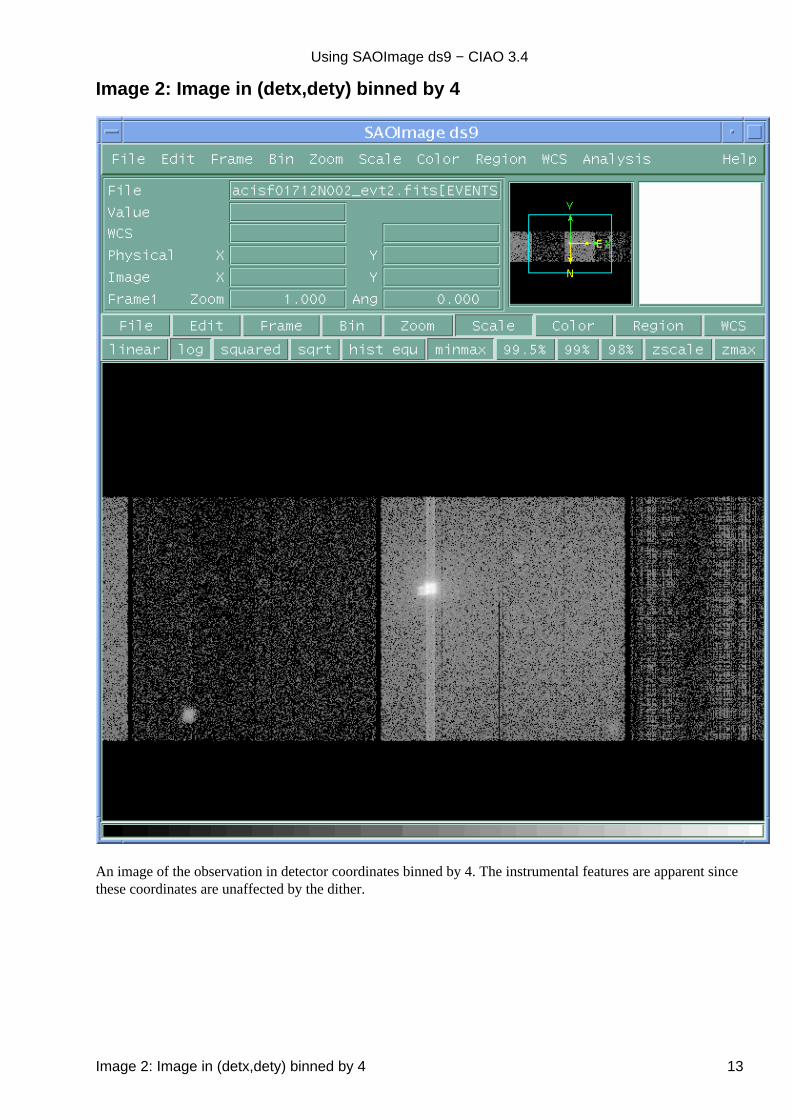
Image 2: Image in (detx,dety) binned by 4
An image of the observation in detector coordinates binned by 4. The instrumental features are apparent sincethese coordinates are unaffected by the dither.
Using SAOImage ds9 − CIAO 3.4
Image 2: Image in (detx,dety) binned by 4 13
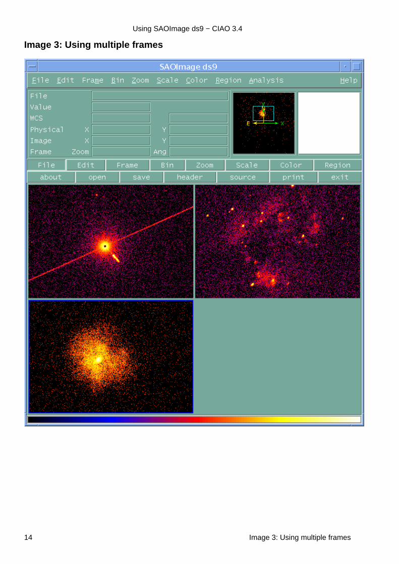
Image 3: Using multiple frames
Using SAOImage ds9 − CIAO 3.4
14 Image 3: Using multiple frames
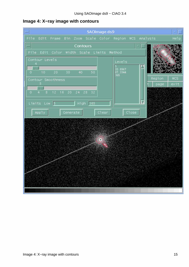
Image 4: X−ray image with contours
Using SAOImage ds9 − CIAO 3.4
Image 4: X−ray image with contours 15
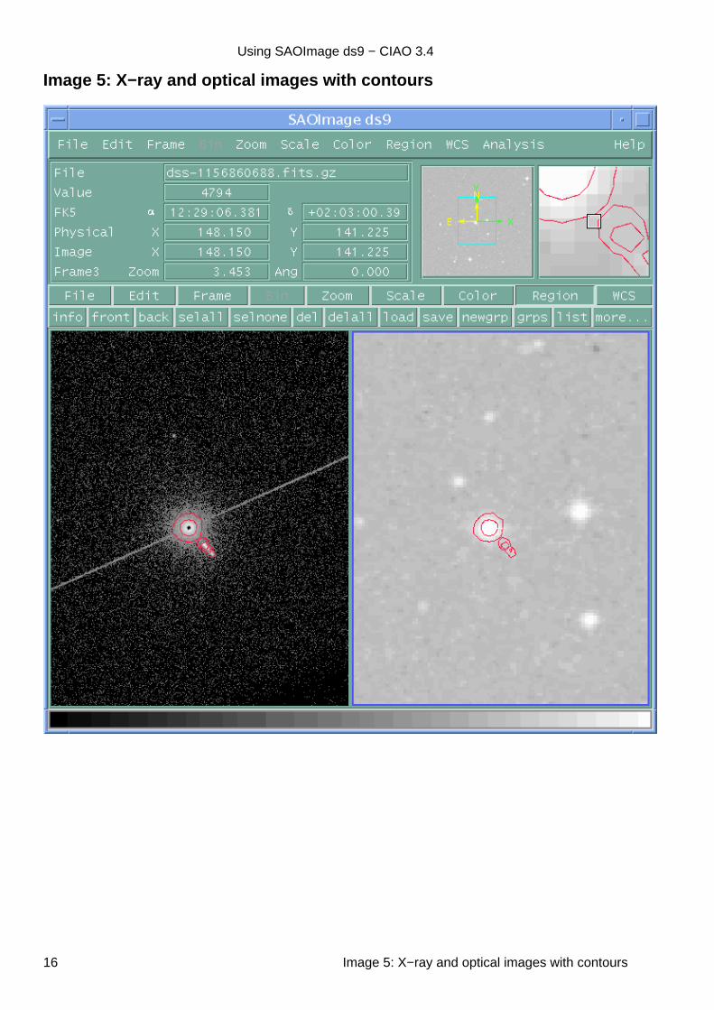
Image 5: X−ray and optical images with contours
Using SAOImage ds9 − CIAO 3.4
16 Image 5: X−ray and optical images with contours

Image 6: Images with contours and locked crosshairs
Using SAOImage ds9 − CIAO 3.4
Image 6: Images with contours and locked crosshairs 17

Using SAOImage ds9 − CIAO 3.4
18 Image 6: Images with contours and locked crosshairs