using infineon’s radar baseboard xmc4700 and bgt24ltr11
TRANSCRIPT
Please read the Important Notice and Warnings at the end of this document
www.infineon.com page 1 of 31 2019-12-02
AN605
Using Infineon’s radar baseboard XMC4700 and
BGT24LTR11 radar shield with Arduino
Set-up guide
About this document
Scope and purpose
This application note provides a step-by-step guide to setting up Infineon’s 24 GHz Sense2GoL Pulse radar
system platform, which is made up of the radar baseboard XMC4700 and BGT24LTR11 radar shield, making up
the hardware and software for use with the Arduino platform. This guide will then go on to show an application
example to demonstrate some of the features of this radar system platform.
Intended audience
This document is intended for anyone interested in using Infineon’s 24 GHz radar system platform with the Arduino platform.
Related documents
Additional information can be found in the supplementary documentation provided with the Sense2GoL Pulse
Kit in the Infineon Toolbox or from www.infineon.com/24GHz:
24 GHz Radar Tools and Development Environment User Manual
Sense2GoL Pulse Software User Manual
AN 598 – BGT24LTR11 Shield (Pulsed Doppler)
AN602 – Radar Baseboard XMC4700
2 of 31
2019-12-02
Using Infineon’s radar baseboard XMC4700 and BGT24LTR11 radar
shield with Arduino Set-up guide Table of contents
Table of contents
About this document ....................................................................................................................... 1
Table of contents ............................................................................................................................ 2
List of figures ................................................................................................................................. 3
List of tables .................................................................................................................................. 4
1 Introduction .......................................................................................................................... 5
2 Hardware modifications ......................................................................................................... 7 2.1 Removal of resistors ................................................................................................................................ 7
2.2 Selection of IOREF ................................................................................................................................... 7 2.3 ISCP header ............................................................................................................................................. 8
3 Software set-up ..................................................................................................................... 9
3.1 Download and install Arduino IDE .......................................................................................................... 9 3.2 Install Infineon’s Arduino package ......................................................................................................... 9
3.3 Using Pulsed Doppler Radar Library ..................................................................................................... 12 3.4 Example sketches .................................................................................................................................. 16
3.4.1 Example 1: Radar_Pulsed_Doppler_LED ........................................................................................ 17 3.4.2 Example 2: RadarPulsedDoppler_Andee_RGB ............................................................................... 20
4 Author ................................................................................................................................. 28
5 References ........................................................................................................................... 29
Revision history............................................................................................................................. 30

3 of 31
2019-12-02
Using Infineon’s radar baseboard XMC4700 and BGT24LTR11 radar
shield with Arduino Set-up guide List of figures
List of figures
Figure 1 Radar baseboard XMC4700 ................................................................................................................. 5 Figure 2 BGT24LTR11 radar shield .................................................................................................................... 6
Figure 3 Resistors to be removed for I2C communication ............................................................................... 7 Figure 4 Jumper selection for IOREF ................................................................................................................ 8 Figure 5 Use SPI pins on P3 instead of P7 (ISCP) .............................................................................................. 8
Figure 6 Downloading the Arduino IDE ............................................................................................................. 9
Figure 7 Arduino IDE: File > Preferences ......................................................................................................... 10 Figure 8 Entering the location from which the package can be downloaded .............................................. 10 Figure 9 Installing the XMC package ............................................................................................................... 11
Figure 10 Selecting XMC baseboard ................................................................................................................. 11
Figure 11 Including and using the Library in Arduino sketch .......................................................................... 12
Figure 12 Declaring Pulsed Doppler Radar object ........................................................................................... 12 Figure 13 Initializing hardware and parameters for Pulsed Doppler Radar .................................................... 13 Figure 14 Example for callback function definition ......................................................................................... 15 Figure 15 Call run() in main loop() .................................................................................................................... 16
Figure 16 Accessing example sketches from this library ................................................................................. 17
Figure 17 Example sketch: Radar_Pulsed_Doppler_LED ................................................................................. 18
Figure 18 Compiling the sketch ........................................................................................................................ 18 Figure 19 Compilation successful ..................................................................................................................... 18
Figure 20 Attach the BGT24LTR11 radar shield to the radar baseboard XMC4700 ......................................... 19 Figure 21 Connect USB cable to debug port .................................................................................................... 19 Figure 22 Uploading code onto board .............................................................................................................. 20
Figure 23 Observe LED color change with motion ........................................................................................... 20
Figure 24 Example sketch: RadarPulsedDopplerLED_Andee_RGB ................................................................. 21 Figure 25 Compiling the sketch ........................................................................................................................ 21
Figure 26 Compilation successful ..................................................................................................................... 22 Figure 27 Attach the BGT24LTR11 shield to the radar baseboard XMC4700 ................................................... 22 Figure 28 Stacking the RGB LED lighting shield onto the radar baseboard XMC4700 .................................... 23
Figure 29 Stacking the Annikken Andee U shield onto the set-up ................................................................... 23 Figure 30 Jumper wire connections on the Andee U ....................................................................................... 24 Figure 31 Connect the USB cable onto the debug port ................................................................................... 24
Figure 32 Uploading the code onto the board ................................................................................................. 25
Figure 33 Application starts with white light .................................................................................................... 25 Figure 34 Andee app – scan for devices ............................................................................................................ 25 Figure 35 Andee app – connect to device ......................................................................................................... 26 Figure 36 Andee app – GUI upon successful connection ................................................................................. 26
Figure 37 Changing pre-defined fast speed threshold ..................................................................................... 27

4 of 31
2019-12-02
Using Infineon’s radar baseboard XMC4700 and BGT24LTR11 radar
shield with Arduino Set-up guide List of tables
List of tables
Table 1 Configuration APIs ............................................................................................................................. 13 Table 2 Result APIs ......................................................................................................................................... 14
Table 3 Control APIs ....................................................................................................................................... 16 Table 4 Example sketches .............................................................................................................................. 17 Table 5 LED color based on motion for Example 1 ....................................................................................... 20 Table 6 LED behavior for Example 2 .............................................................................................................. 27
5 of 31
2019-12-02
Using Infineon’s radar baseboard XMC4700 and BGT24LTR11 radar
shield with Arduino Set-up guide Introduction
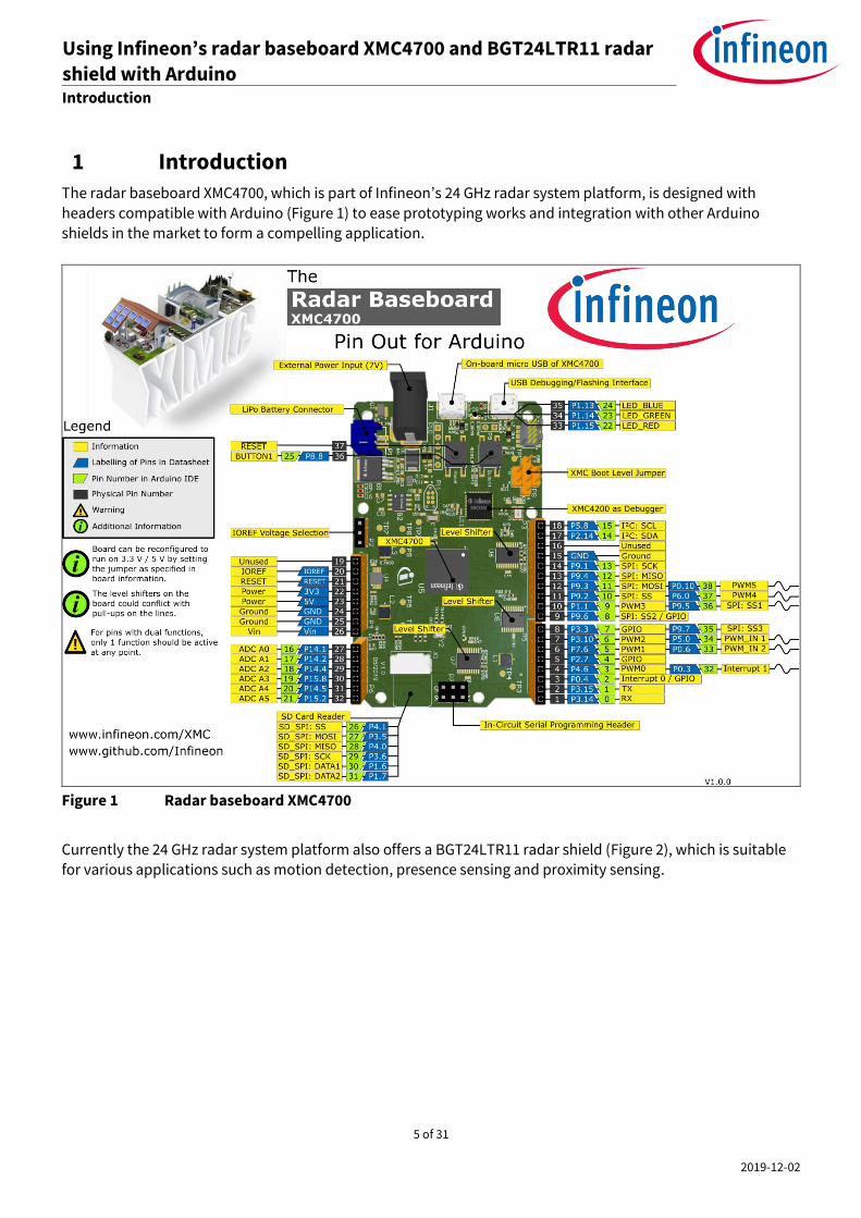
1 Introduction
The radar baseboard XMC4700, which is part of Infineon’s 24 GHz radar system platform, is designed with
headers compatible with Arduino (Figure 1) to ease prototyping works and integration with other Arduino shields in the market to form a compelling application.
Figure 1 Radar baseboard XMC4700
Currently the 24 GHz radar system platform also offers a BGT24LTR11 radar shield (Figure 2), which is suitable
for various applications such as motion detection, presence sensing and proximity sensing.
6 of 31
2019-12-02
Using Infineon’s radar baseboard XMC4700 and BGT24LTR11 radar
shield with Arduino Set-up guide Introduction
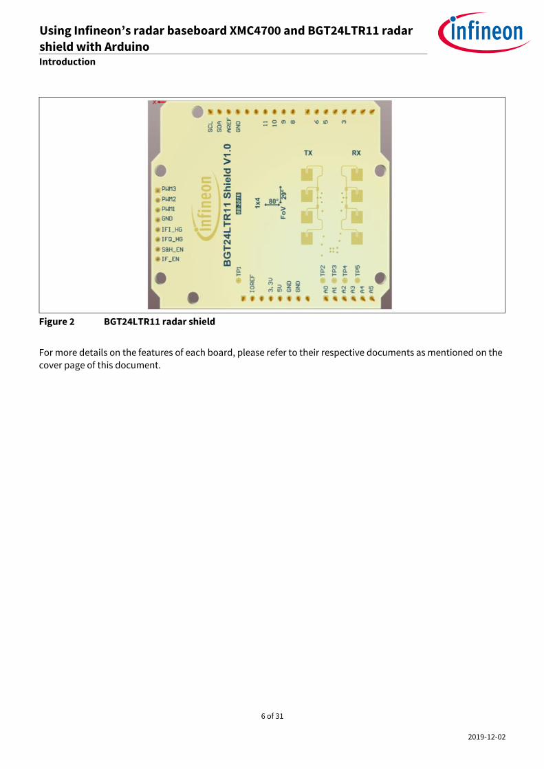
Figure 2 BGT24LTR11 radar shield
For more details on the features of each board, please refer to their respective documents as mentioned on the cover page of this document.

7 of 31
2019-12-02
Using Infineon’s radar baseboard XMC4700 and BGT24LTR11 radar
shield with Arduino Set-up guide Hardware modifications
2 Hardware modifications
This section highlights some of the changes required to be made to the hardware before interfacing the radar
baseboard XMC4700 with other Arduino shields.
2.1 Removal of resistors
If I2C communication is intended to be used as the interface to the target Arduino shield, remove the following resistors (Figure 3): R70, R71, R73, R74, R77 and R80.
Figure 3 Resistors to be removed for I2C communication
2.2 Selection of IOREF
XMC4700 operates in the 3.3 V domain. Depending on the target Arduino shield, the IOREF can be configured as
5 V or 3.3 V via a jumper on P2 (Figure 4).
To select 3.3 V as IOREF, short pins 1 and 2 of P2.
To select 5 V as IOREF, short pins 2 and 3 of P2.

8 of 31
2019-12-02
Using Infineon’s radar baseboard XMC4700 and BGT24LTR11 radar
shield with Arduino Set-up guide Hardware modifications
Figure 4 Jumper selection for IOREF
2.3 ISCP header
In case connection via the ISCP header is required to the target Arduino shield, do not use the pins from header P7. Instead, connect the pins via jumper wires from the SPI pins on header P3 (Figure 5).
Figure 5 Use SPI pins on P3 instead of P7 (ISCP)

9 of 31
2019-12-02
Using Infineon’s radar baseboard XMC4700 and BGT24LTR11 radar
shield with Arduino Set-up guide Software set-up
3 Software set-up
This section highlights the steps needed in order to use Infineon’s 24 GHz radar system platform with the
Arduino IDE.
3.1 Download and install Arduino IDE
The first step is to download the latest Arduino IDE version from https://www.arduino.cc/en/main/software (Figure 6). Select the desired installation type and follow the installation instructions accordingly.
Figure 6 Downloading the Arduino IDE
3.2 Install Infineon’s Arduino package
1. Launch the Arduino IDE.
2. Navigate to File > Preferences (Figure 7).
3. Copy the following URL into the “Additional Boards Manager URLs” field (Figure 8):
https://github.com/Infineon/Assets/releases/download/current/package_infineon_index.json
Once done, click “OK”.
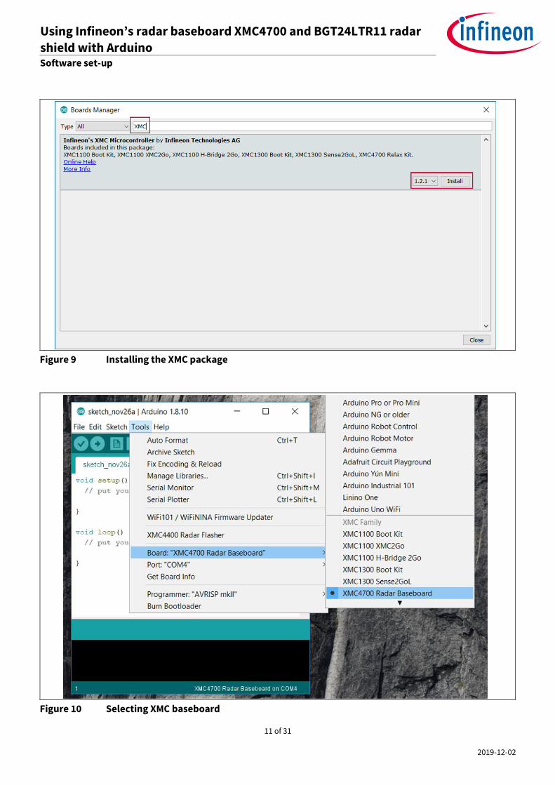
4. Navigate to Tools > Board > Boards Manager (Figure 9). Type “XMC” into the search field. Select the latest version from the drop-down box and click “Install”.
5. Once installation is completed, the XMC-based microcontroller boards can be found and selected under Tools > Board (Figure 10).

10 of 31
2019-12-02
Using Infineon’s radar baseboard XMC4700 and BGT24LTR11 radar
shield with Arduino Set-up guide Software set-up
Figure 7 Arduino IDE: File > Preferences
Figure 8 Entering the location from which the package can be downloaded
11 of 31
2019-12-02
Using Infineon’s radar baseboard XMC4700 and BGT24LTR11 radar
shield with Arduino Set-up guide Software set-up
Figure 9 Installing the XMC package
Figure 10 Selecting XMC baseboard

12 of 31
2019-12-02
Using Infineon’s radar baseboard XMC4700 and BGT24LTR11 radar
shield with Arduino Set-up guide Software set-up
3.3 Using Pulsed Doppler Radar Library
The Pulsed Doppler Radar Library is installed as part of the core libraries for XMC when the XMC Arduino package is installed as shown in Section 3.2.
1. To use the Pulsed Doppler Radar Library in Arduino sketch, it must first be added via Sketch > Include Library
> IFXRadarPulsedDoppler (Figure 11).
Figure 11 Including and using the Library in Arduino sketch
2. Next, declare a Radar Pulsed Doppler object, such as shown in Figure 12.
Figure 12 Declaring Pulsed Doppler Radar object

13 of 31
2019-12-02
Using Infineon’s radar baseboard XMC4700 and BGT24LTR11 radar
shield with Arduino Set-up guide Software set-up
3. Next, some steps are required to initialize the hardware for the Pulsed Doppler Radar and also to configure the parameters. All these are to be done within the setup() routine (Figure 13).
Figure 13 Initializing hardware and parameters for Pulsed Doppler Radar
The lines of code will initialize the software to use the default parameters. In case custom parameters are preferred, the user can call the respective APIs (as listed in Table 1) before calling the begin() function.
Table 1 Configuration APIs
API name Description
uint8_t setMinSpeed(float speedMs); Set the minimum speed that will be detected
float getMinSpeed(void); Retrieve the minimum speed configured
uint8_t setMaxSpeed(float speedMs); Set maximum speed that will be detected
float getMaxSpeed(void); Retrieve the maximum speed configured
uint8_t setMotionSensitivity(float threshold); Set threshold that will determine motion or not
float getMotionSensitivity(void); Retrieve threshold that will determine motion or not
uint8_t setDopplerSensitivity(float threshold); Set threshold that will determine motion with
direction (departing/approaching) or not

14 of 31
2019-12-02
Using Infineon’s radar baseboard XMC4700 and BGT24LTR11 radar
shield with Arduino Set-up guide Software set-up
API name Description
float getDopplerSensitivity(void); Retrieve threshold that will determine motion with
direction (departing/approaching) or not
uint8_t setFramePeriod(uint8_t periodUs); Set frame period in µs
uint8_t getFramePeriod(void); Retrieve configured frame period in µs
uint8_t setSampleFreq(uint32_t frequencyHz); Set ADC sampling frequency in Hz
uint32_t getSampleFreq(void); Retrieve ADC sampling frequency in Hz
uint8_t setSkipSamples(uint32_t numSamples); Set the number of samples to skip at beginning of
frame
uint32_t getSkipSamples(void); Retrieve the number of samples to skip at beginning
of frame
uint8_t setNumSamples(uint32_t numSamples); Set size of raw IQ ADC buffer
uint32_t getNumSamples(void); Retrieve configured size of raw IQ ADC buffer
uint8_t setPulseWidth(uint32_t widthUs); Set the pulse width in µs
uint32_t getPulseWidth(void); Retrieve the configured pulse width in µs
uint32_t getMinFramePeriod(void); Get the minimum frame period in µs
4. Next, define the callback function to perform application tasks upon completion of a round of radar processing, for example to turn on or off an LED. In the example shown in Figure 14, different LED colors are used to indicate different radar processing results. Table 2 lists the APIs that can be called to retrieve the
result of the radar processing.
Table 2 Result APIs
API name Description
bool targetAvailable(void); Returns true: motion (with no direction), false: no
motion
float getDopplerLevel(void); Retrieve the Doppler level of the detected target
float getDopplerFreqHz(void); Retrieve the Doppler frequency of the detected
target
float getVelocity(void); Retrieve the signed velocity value
uint8_t getDirection(void); Returns 0: no direction, 1: departing, 2: approaching
float getSpeed(void); Retrieve the unsigned speed value

15 of 31
2019-12-02
Using Infineon’s radar baseboard XMC4700 and BGT24LTR11 radar
shield with Arduino Set-up guide Software set-up
Figure 14 Example for callback function definition
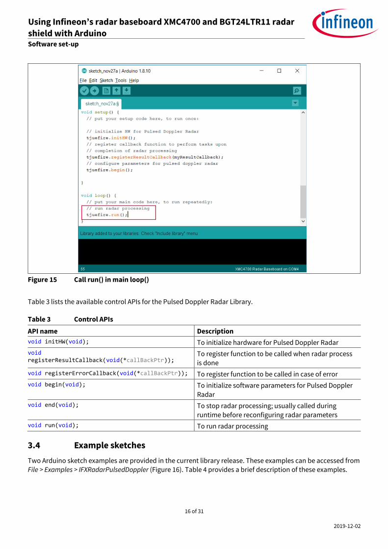
5. Finally, add the run() API in the loop() routine to run the radar processing (Figure 15).
16 of 31
2019-12-02
Using Infineon’s radar baseboard XMC4700 and BGT24LTR11 radar
shield with Arduino Set-up guide Software set-up
Figure 15 Call run() in main loop()
Table 3 lists the available control APIs for the Pulsed Doppler Radar Library.
Table 3 Control APIs
API name Description
void initHW(void); To initialize hardware for Pulsed Doppler Radar
void registerResultCallback(void(*callBackPtr));
To register function to be called when radar process
is done
void registerErrorCallback(void(*callBackPtr)); To register function to be called in case of error
void begin(void); To initialize software parameters for Pulsed Doppler
Radar
void end(void); To stop radar processing; usually called during
runtime before reconfiguring radar parameters
void run(void); To run radar processing
3.4 Example sketches
Two Arduino sketch examples are provided in the current library release. These examples can be accessed from File > Examples > IFXRadarPulsedDoppler (Figure 16). Table 4 provides a brief description of these examples.

17 of 31
2019-12-02
Using Infineon’s radar baseboard XMC4700 and BGT24LTR11 radar
shield with Arduino Set-up guide Software set-up
Figure 16 Accessing example sketches from this library
Table 4 Example sketches
Sketch name Required HW Description
Radar_Pulsed_Doppler
_LED
Radar baseboard XMC4700 and BGT24LTR11 radar
shield
Use on-board LED to
indicate detection of motion and direction
of motion
RadarPulsedDoppler
_Andee_RGB
1) Radar baseboard XMC4700 and BGT24LTR11 radar
shield
2) Annikken Andee U shield
(https://www.annikken.com/andee-u)
3) RGB LED lighting shield with XMC1202 (https://www.infineon.com/cms/en/product/evaluation-
boards/kit_led_xmc1202_as_01/)
Project and display the results of radar
processing on a smart
device (e.g. cell phone/tablet) via
Bluetooth, and at the same time using an
external RGB LED to indicate motion and
direction of motion
3.4.1 Example 1: Radar_Pulsed_Doppler_LED
This section lists the steps to follow to get this example up and running.
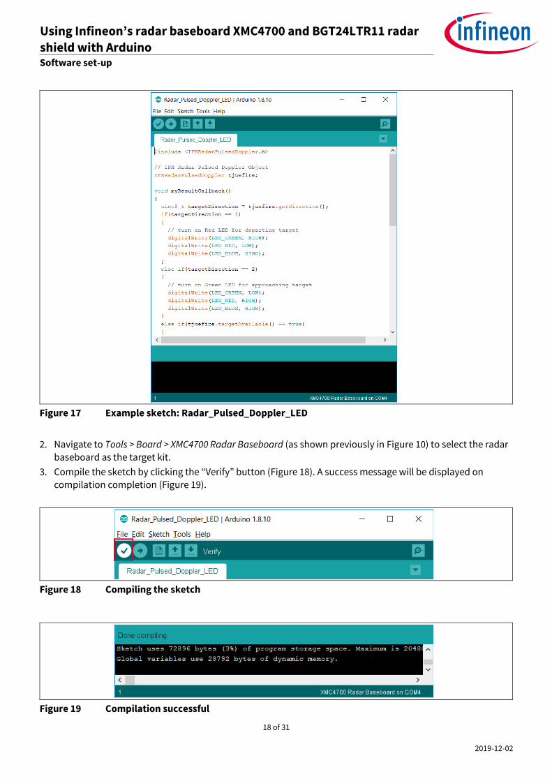
1. In Arduino IDE, navigate to File > Examples > IFXRadarPulsedDoppler > Radar_Pulsed_Doppler_LED (as shown previously in Figure 16). The sketch will open (Figure 17).
18 of 31
2019-12-02
Using Infineon’s radar baseboard XMC4700 and BGT24LTR11 radar
shield with Arduino Set-up guide Software set-up
Figure 17 Example sketch: Radar_Pulsed_Doppler_LED
2. Navigate to Tools > Board > XMC4700 Radar Baseboard (as shown previously in Figure 10) to select the radar baseboard as the target kit.
3. Compile the sketch by clicking the “Verify” button (Figure 18). A success message will be displayed on
compilation completion (Figure 19).
Figure 18 Compiling the sketch
Figure 19 Compilation successful

19 of 31
2019-12-02
Using Infineon’s radar baseboard XMC4700 and BGT24LTR11 radar
shield with Arduino Set-up guide Software set-up
4. Attach the BGT24LTR11 radar shield to the radar baseboard XMC4700 via the SAMTEC connectors (Figure 20).
Figure 20 Attach the BGT24LTR11 radar shield to the radar baseboard XMC4700
5. Connect the radar baseboard XMC4700 to the PC via a USB cable onto the “Debug” USB port (Figure 21).
Figure 21 Connect USB cable to debug port
20 of 31
2019-12-02
Using Infineon’s radar baseboard XMC4700 and BGT24LTR11 radar
shield with Arduino Set-up guide Software set-up
6. Upload the code onto the board by clicking the “Upload” button (Figure 22).
Figure 22 Uploading code onto board
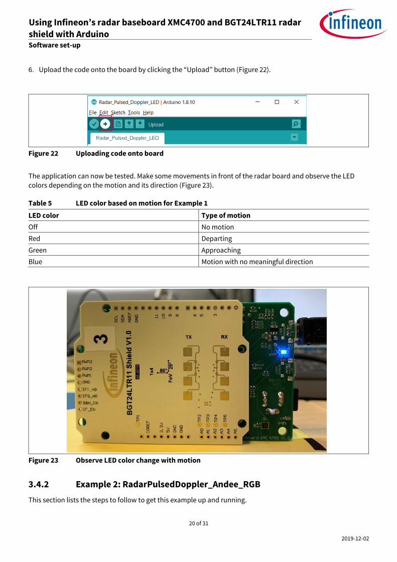
The application can now be tested. Make some movements in front of the radar board and observe the LED
colors depending on the motion and its direction (Figure 23).
Table 5 LED color based on motion for Example 1
LED color Type of motion
Off No motion
Red Departing
Green Approaching
Blue Motion with no meaningful direction
Figure 23 Observe LED color change with motion
3.4.2 Example 2: RadarPulsedDoppler_Andee_RGB
This section lists the steps to follow to get this example up and running.
21 of 31
2019-12-02
Using Infineon’s radar baseboard XMC4700 and BGT24LTR11 radar
shield with Arduino Set-up guide Software set-up
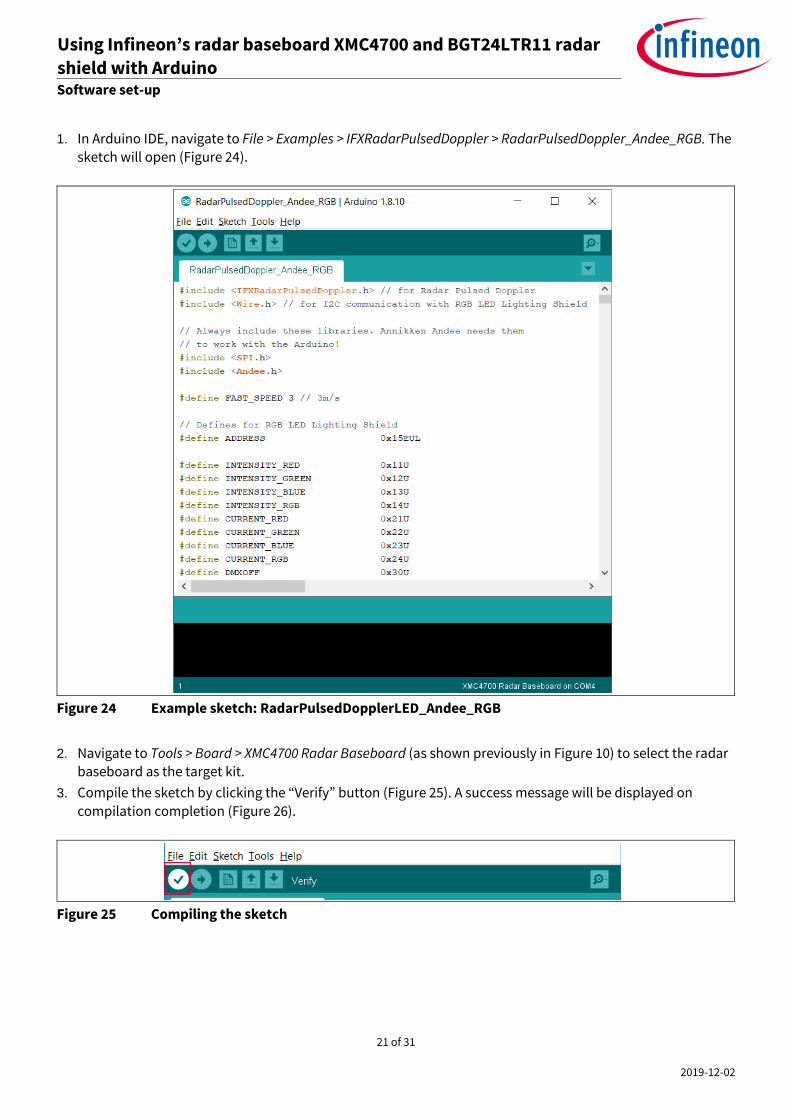
1. In Arduino IDE, navigate to File > Examples > IFXRadarPulsedDoppler > RadarPulsedDoppler_Andee_RGB. The sketch will open (Figure 24).
Figure 24 Example sketch: RadarPulsedDopplerLED_Andee_RGB
2. Navigate to Tools > Board > XMC4700 Radar Baseboard (as shown previously in Figure 10) to select the radar baseboard as the target kit.
3. Compile the sketch by clicking the “Verify” button (Figure 25). A success message will be displayed on
compilation completion (Figure 26).
Figure 25 Compiling the sketch
22 of 31
2019-12-02
Using Infineon’s radar baseboard XMC4700 and BGT24LTR11 radar
shield with Arduino Set-up guide Software set-up
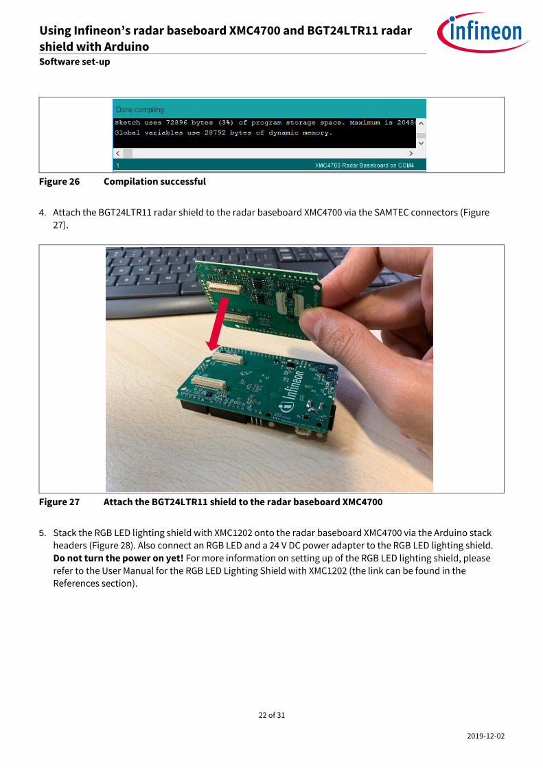
Figure 26 Compilation successful
4. Attach the BGT24LTR11 radar shield to the radar baseboard XMC4700 via the SAMTEC connectors (Figure 27).
Figure 27 Attach the BGT24LTR11 shield to the radar baseboard XMC4700
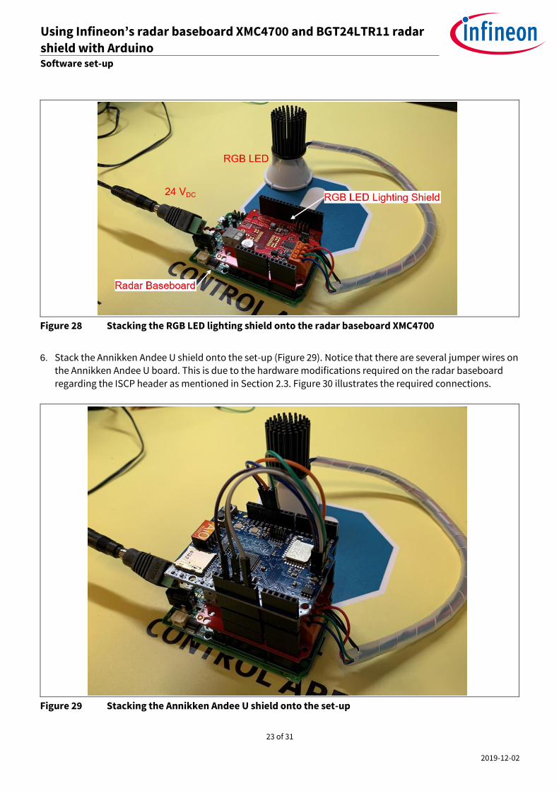
5. Stack the RGB LED lighting shield with XMC1202 onto the radar baseboard XMC4700 via the Arduino stack
headers (Figure 28). Also connect an RGB LED and a 24 V DC power adapter to the RGB LED lighting shield.
Do not turn the power on yet! For more information on setting up of the RGB LED lighting shield, please
refer to the User Manual for the RGB LED Lighting Shield with XMC1202 (the link can be found in the References section).
23 of 31
2019-12-02
Using Infineon’s radar baseboard XMC4700 and BGT24LTR11 radar
shield with Arduino Set-up guide Software set-up
Figure 28 Stacking the RGB LED lighting shield onto the radar baseboard XMC4700
6. Stack the Annikken Andee U shield onto the set-up (Figure 29). Notice that there are several jumper wires on
the Annikken Andee U board. This is due to the hardware modifications required on the radar baseboard
regarding the ISCP header as mentioned in Section 2.3. Figure 30 illustrates the required connections.
Figure 29 Stacking the Annikken Andee U shield onto the set-up

24 of 31
2019-12-02
Using Infineon’s radar baseboard XMC4700 and BGT24LTR11 radar
shield with Arduino Set-up guide Software set-up
Figure 30 Jumper wire connections on the Andee U
7. Turn on the 24 V DC power supply to the RGB LED lighting shield and connect the radar baseboard XMC4700
to the PC via a USB cable onto the “Debug” USB port (Figure 31).
Figure 31 Connect the USB cable onto the debug port
8. Upload the code onto the board by clicking the “Upload” button (Figure 32).

25 of 31
2019-12-02
Using Infineon’s radar baseboard XMC4700 and BGT24LTR11 radar
shield with Arduino Set-up guide Software set-up
Figure 32 Uploading the code onto the board
The RGB LED should turn on with white light, while the on-board LED will cycle between red, green and blue
light to show radar processing is taking place (Figure 33). The application can now be tested.
Figure 33 Application starts with white light
9. Launch the Andee app (can be installed for free from the Apple App Store or Google Play Store) on your smart device. In the app, click “Scan for Devices” (Figure 34).
Figure 34 Andee app – scan for devices
10. Click “Tjuefire”. When prompted, click “Connect” (Figure 35).
26 of 31
2019-12-02
Using Infineon’s radar baseboard XMC4700 and BGT24LTR11 radar
shield with Arduino Set-up guide Software set-up
Figure 35 Andee app – connect to device
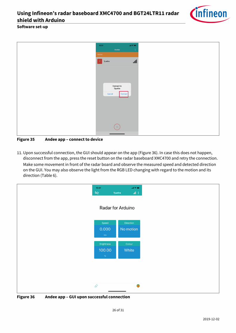
11. Upon successful connection, the GUI should appear on the app (Figure 36). In case this does not happen, disconnect from the app, press the reset button on the radar baseboard XMC4700 and retry the connection.
Make some movement in front of the radar board and observe the measured speed and detected direction
on the GUI. You may also observe the light from the RGB LED changing with regard to the motion and its
direction (Table 6).
Figure 36 Andee app – GUI upon successful connection

27 of 31
2019-12-02
Using Infineon’s radar baseboard XMC4700 and BGT24LTR11 radar
shield with Arduino Set-up guide Software set-up
Table 6 LED behavior for Example 2
LED behavior Type of motion
Dims down Departing
Brightens Approaching
Changes color Motion with speed above pre-defined threshold
The pre-defined fast speed threshold can be changed within the Arduino sketch (Figure 37).
Figure 37 Changing pre-defined fast speed threshold
28 of 31
2019-12-02
Using Infineon’s radar baseboard XMC4700 and BGT24LTR11 radar
shield with Arduino Set-up guide Author
4 Author
Mohamed Saat Muhammad Nur Syafii
29 of 31
2019-12-02
Using Infineon’s radar baseboard XMC4700 and BGT24LTR11 radar
shield with Arduino Set-up guide References
5 References
[1] Infineon BGT24LTR11N16 – 24 GHz Radar IC – Datasheet
[2] Infineon BGT24LTR11 – Product Brief
[3] Infineon Application Note – AN472 – “User’s Guide to BGT24LTR11N16”
[4] 24 GHz industrial radar – FAQs
[5] ETSI Regulations – EN 300 440 V2.2.1
[6] FCC Regulations – 15.245, 15.249
[7] Infineon RGB LED Lighting Shield with XMC1202 for Arduino - User Manual
[8] Annikken Andee U - Documentation

30 of 31
2019-12-02
Using Infineon’s radar baseboard XMC4700 and BGT24LTR11 radar
shield with Arduino Set-up guide References
Revision history
Document
version
Date of release Description of changes
V1.0 02-07-2020 First release
Trademarks All referenced product or service names and trademarks are the property of their respective owners.
Edition 2019-12-02
AN605
Published by
Infineon Technologies AG
81726 Munich, Germany
© 2020 Infineon Technologies AG.
All Rights Reserved.
Do you have a question about this
document?
Email: [email protected]
Document reference AN_1911_PL32_1911_101730
IMPORTANT NOTICE The information contained in this application note is given as a hint for the implementation of the product only and shall in no event be regarded as a description or warranty of a certain functionality, condition or quality of the product. Before implementation of the product, the recipient of this application note must verify any function and other technical information given herein in the real application. Infineon Technologies hereby disclaims any and all warranties and liabilities of any kind (including without limitation warranties of non-infringement of intellectual property rights of any third party) with respect to any and all information given in this application note. The data contained in this document is exclusively intended for technically trained staff. It is the responsibility of customer’s technical departments to evaluate the suitability of the product for the intended application and the completeness of the product information given in this document with respect to such application.
For further information on the product, technology, delivery terms and conditions and prices please contact your nearest Infineon Technologies office (www.infineon.com).
WARNINGS Due to technical requirements products may contain dangerous substances. For information on the types in question please contact your nearest Infineon Technologies office. Except as otherwise explicitly approved by Infineon Technologies in a written document signed by authorized representatives of Infineon Technologies, Infineon Technologies’ products may not be used in any applications where a failure of the product or any consequences of the use thereof can reasonably be expected to result in personal injury.