using ibeacon for newborns localization in hospitals paper/zhouchiismict.pdf · ibeacon is a class...
TRANSCRIPT
Using iBeacon for Newborns Localization in Hospitals
Zhouchi Li, Yang Yang and Kaveh Pahlavan Center for Wireless Information Network Studies (CWINS)
Worcester Polytechnic Institute (WPI), Worcester, MA, 01609 Email: {zli4, yyang9 and kaveh}@wpi.edu
Abstract—iBeacon, a novel beacon device aiming at proximity estimation was introduced in 2014 by Apple Inc. based on Bluetooth Low Energy (BLE) technology. iBeacon is utilized in our work to establish an in-room newborns localization system in hospitals. Since iBeacon can broadcast beacon signal every certain interval, we can adopt iBeacon instead of Radio Frequency Identification (RFID) for baby tracking. In this paper we developed a new application to obtain the necessary data from iBeacon and then derive the real path-loss model for line-of-sight (LOS) situation in in-room environment on account of received signal strength indication (RSSI) analysis. Besides, we apply the iBeacon model used in Estimote iBeacons and compare the performance of those two models. Simulation results of Cramér-Rao low bound (CRLB) estimation of location error model are also given in this paper considering 2D and 3D scenarios respectively. After the feasibility analysis we conclude our work with a discussion on the feasibility of using iBeacon for locating and tracking rather than RFID, especially in hospitals.
Keywords—iBeacon; In-room; Newborns; Localization; Hospital;
I. INTRODUCTION In hospitals one of the most important tasks is the safety of
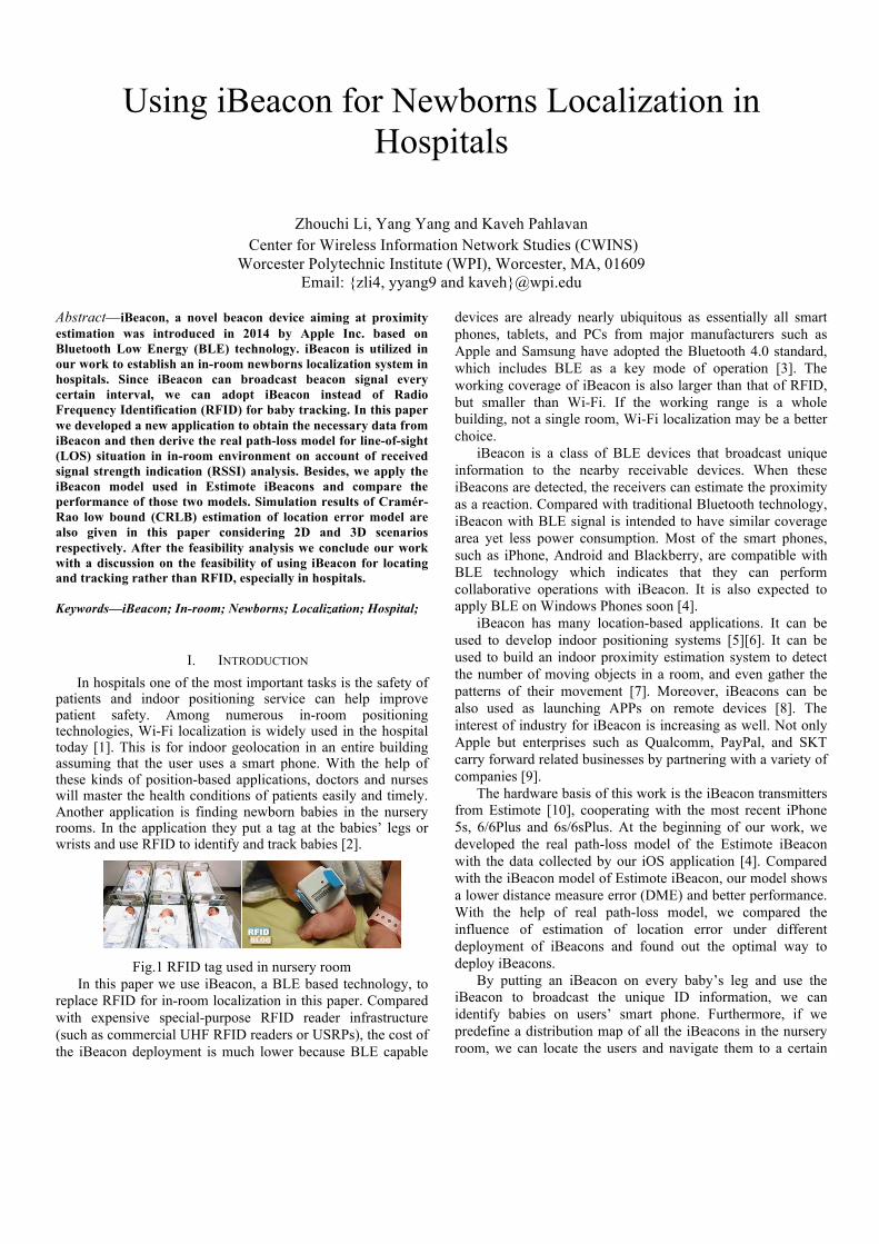
patients and indoor positioning service can help improve patient safety. Among numerous in-room positioning technologies, Wi-Fi localization is widely used in the hospital today [1]. This is for indoor geolocation in an entire building assuming that the user uses a smart phone. With the help of these kinds of position-based applications, doctors and nurses will master the health conditions of patients easily and timely. Another application is finding newborn babies in the nursery rooms. In the application they put a tag at the babies’ legs or wrists and use RFID to identify and track babies [2].
Fig.1 RFID tag used in nursery room
In this paper we use iBeacon, a BLE based technology, to replace RFID for in-room localization in this paper. Compared with expensive special-purpose RFID reader infrastructure (such as commercial UHF RFID readers or USRPs), the cost of the iBeacon deployment is much lower because BLE capable
devices are already nearly ubiquitous as essentially all smart phones, tablets, and PCs from major manufacturers such as Apple and Samsung have adopted the Bluetooth 4.0 standard, which includes BLE as a key mode of operation [3]. The working coverage of iBeacon is also larger than that of RFID, but smaller than Wi-Fi. If the working range is a whole building, not a single room, Wi-Fi localization may be a better choice.
iBeacon is a class of BLE devices that broadcast unique information to the nearby receivable devices. When these iBeacons are detected, the receivers can estimate the proximity as a reaction. Compared with traditional Bluetooth technology, iBeacon with BLE signal is intended to have similar coverage area yet less power consumption. Most of the smart phones, such as iPhone, Android and Blackberry, are compatible with BLE technology which indicates that they can perform collaborative operations with iBeacon. It is also expected to apply BLE on Windows Phones soon [4].
iBeacon has many location-based applications. It can be used to develop indoor positioning systems [5][6]. It can be used to build an indoor proximity estimation system to detect the number of moving objects in a room, and even gather the patterns of their movement [7]. Moreover, iBeacons can be also used as launching APPs on remote devices [8]. The interest of industry for iBeacon is increasing as well. Not only Apple but enterprises such as Qualcomm, PayPal, and SKT carry forward related businesses by partnering with a variety of companies [9].
The hardware basis of this work is the iBeacon transmitters from Estimote [10], cooperating with the most recent iPhone 5s, 6/6Plus and 6s/6sPlus. At the beginning of our work, we developed the real path-loss model of the Estimote iBeacon with the data collected by our iOS application [4]. Compared with the iBeacon model of Estimote iBeacon, our model shows a lower distance measure error (DME) and better performance. With the help of real path-loss model, we compared the influence of estimation of location error under different deployment of iBeacons and found out the optimal way to deploy iBeacons.
By putting an iBeacon on every baby’s leg and use the iBeacon to broadcast the unique ID information, we can identify babies on users’ smart phone. Furthermore, if we predefine a distribution map of all the iBeacons in the nursery room, we can locate the users and navigate them to a certain
baby according to RSSI analysis. Different deployment patterns will result in different localization performance, which can be quantified by real path-loss modeling and 3D CRLB analysis of iBeacons.
The rest of the paper is organized as follows. In section II, we derive the real path-loss model based on our data collecting system and compare the performance of that model with Estimote iBeacon model by the cumulative distribution function (CDF) of DME. In section III, we simulate the in-room environment to do Cramér-Rao low bound estimation of location error both in 2D and 3D scenarios. In section IV, we compare the CDF of the error in three different deployment patterns as well as different number of iBeacons. In section V, we draw our conclusions and discuss future works.
II. PATH-LOSS MODELING In this part, we introduce our data collecting system
based on which we do RSSI measurements and derive the real path-loss model. Then we compare the performance of that model and iBeacon model by the CDF of DME to reach the conclusion that our real model is more reliable. This model will be used in the simulations in the rest parts.
A. RSSI Data collection system The iBeacons produced by Estimote company can provide
us much information we need such as RSSI, broadcasting interval, minor and major values and even motion sensor. Minor and major values can be defined by users, which can be used to distinguish every iBeacon. However, the existing app from Estimote company do not allow us to collect data directly from iPhone which means large samples are impossible and we can only collect data by hand. To solve this problem, we decide to develop our own app.
We use Objective-C to develop our app to get the RSSI of the beacons. The iPhone 5s acts as the receiver in our research and it is connected to a Mac book computer by a cable. When it gets the packets from iBeacons which are in the detection range, it will display the current values of RSSI both on the iPhone screen and Mac book computer. The data we collected in different situation can be used to do the channel modeling.
The achievements of our developing own app: 1. Connect with certain iBeacon. 2. Set the UUID, major and minor fields of iBeacon. 3. Collect and store the RSSI information. 4. Extract the RSSI data from iPhone. This makes the
data more reliable compared with those collected by hand, and also make the samples much larger.
B. Modeling and validation Before we start to collect data, we need to validate the
measurement environment can use the IEEE 802.11A [11] model or not. Since RSSI is the most important factor in this project, the real path-loss model must be established. We do linear match fitting with different iBeacon data collected by our app to try to find out the real path-loss model of iBeacon. DME is the criterion we use to compare the performance of
each model. The CDF of DME of different models can tell us which model is better.
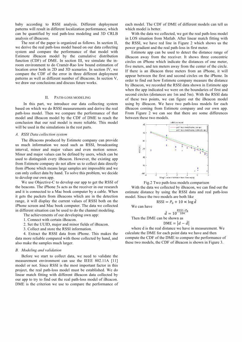
With the data we collected, we got the real path-loss model in LOS situation from Matlab. After linear match fitting with the RSSI, we have red line in Figure 2 which shows us the power gradient and the real path-loss in first meter.
Estimote app can be used to detect the distance range of iBeacon away from the receiver. It shows three concentric circles on iPhone which indicate the distances of one meter, five meters, and ten meters away from the center of the circle. If there is an iBeacon three meters from an iPhone, it will appear between the first and second circles on the iPhone. In order to find out how Estimote company measure the distance by iBeacon, we recorded the RSSI data shown in Estimote app when the app indicated we were on the boundaries of first and second circles (distances are 1m and 5m). With the RSSI data of these two points, we can figure out the iBeacon model using by iBeacon. We have two path-loss models for each iBeacon coming from Estimote company and our own app. From Figure 2 we can see that there are some differences between these two models.
Fig.2 Two path-loss models comparison
With the data we collected by iBeacon, we can find out the estimate distance by using the RSSI data and real path-loss model. Since the two models are both like
RSSI = !! + 10 ∝ log ! We can have
! = 10!""#!!!!"∝
Then the DME can be shown as DME = ! − !
where d is the real distance we have in measurement. We calculate the DME for each point data we have and then compute the CDF of the DME to compare the performance of these two models, the CDF of iBeacon is shown in Figure 3.

Fig.3 Comparison of DME CDF
From Figure 3 we can see that the red CDF is on the left side of green CDF which means real path-loss model coming from linear match fitting has less error in the same DME range. In a word, real path-loss model shows a better performance.
C. Overall path-loss modeling results. In this part, different iBeacons have different path-loss
model which may be caused by shadow fading or measurement error. However, after comparing the CDF of DME, real path-loss model shows a better performance, using real path-loss model may have a better distance judgement. The overall two path-loss models are shown in table-1, where �SF(m) means the mean of shadow fading using each model.
Item iBeacon model Real path-loss model
Characteristic L0(dB) � �SF(dB) L0 � �SF(dB)
iBeacon1 -54.8995 2.5214 3.2013 -55.3555 2.4674 3.5773
iBeacon2 -55.5000 2.2540 4.2992 -56.8918 2.3689 3.0501
iBeacon3 -52.5628 2.7693 4.1208 -56.1283 2.5387 3.1099
Table-1 Two different path-loss models Based on the models, we also calculate the DME of each
model to decide which one owes a better performance, the comparison results are shown in table-2, where me(m) means the mean of DME using each model and σe(m) means the standard variance of DME using each model.
Item iBeacon model Real path-loss model
Characteristic me(m) �e(m) me(m) σe(m)
iBeacon1 0.8716 1.1819 0.8771 1.2179
iBeacon2 1.6717 4.9553 1.0788 1.4071
iBeacon3 0.1739 2.0837 0.9872 1.9240
Table-2 DME comparison of two models
III. PERFORMANCE EVALUATION METHODS In this part, we firstly introduce the scenarios we define
to evaluate the performance of using iBeacon in localization. Then based on Matlab, we simulate the in-room localization environment and calculate the estimation of location error to show the effects of different deployment patterns and different iBeacon numbers. Furthermore, we promote our model from 2D to 3D scenario and figure out the estimation of location error to present the feasibility in this case.
A. Performance evaluation scenarios. In order to compare the performance of different
localization methods, in this paper we use Cramér-Rao low bound of the location error standard deviation as the assessment criterion. According to the conclusion given in Signal Strength Based Indoor Geolocation [12], we know how to calculate the location error standard deviation. We use Matlab simulation to obtain the theoretic results.
Fig.4 Scenarios of different deployment methods
Since we want find the most efficient way of localization, different deployment methods are introduced, based on which we can compare and make conclusion. It is easy to know that more iBeacons stands for more localization accuracy, but what we pursue is how to reach the highest accuracy with special given iBeacons, so there are 3 scenarios we simulated. In the first scenario, there are four iBeacons in the four corners of the room and another one in the middle of the room. As for the second scenario, there are four iBeacons in the four corners of the middle area of the room and also another one in the middle of the room. To the last scenario, it is almost as the same as the second one, except for the rotation of 45 degrees of the four iBeacons deployed in the middle area, which means we rotate the square formed by the second deployment method with 45 degrees into a new deployment pattern.
B. Localization error estimation of deployment patterns. As we discussed before, there are 3 scenarios we analyze
and compare in order to evaluate the feasibility and effectiveness. From the Matlab we have such conclusions. The simulation conditions for location error analysis are as follows:
Pr(0) = 160W = 52dBm, and α = 2.4583 which is the mean of the α values of real path-loss model derived in part II (shown in Table-1).
In the first scenario, we assume that there are five APs installed in a building with their coordinates being AP 1 (15m, 15m), AP 2 (15m, -15m), AP 3 (-15m, -15m), AP 4 (-15m, 15m), and AP 5 (0.1m, 0.1m). If an MS at a given location receives signals from these APs, its position can be determined by triangulation or least square estimation. The simulation result is shown in Figure 5.

Fig.5 Contour of estimate location error in 2D
Then we move the four iBeacons from four corners to the middle area of the room to reach the second scenario and also make such type figure. When we come to the last scenario, we just do a rotation of 90 degrees with the four iBeacons in the middle and reach the result.
C. CRLB for performance evaluation in 3D. Since the nursery room is a cube in reality, we extend the
formula and simulation conditions from 2D to 3D. Z axis is introduced into the original x × y plane and we also move the fifth iBeacon from the middle of ground up to the middle of the roof.
Based on the well-known path-loss model [12][13][14], we have:
00
P( r ) [ dBm] P( r ) [ dBm] 10 l og( )rr
α= −
Transfer it into 3D coordinate form:
2 2 2
10( x, y, z ) ( dx dy dz)l n 10
i i ii
i i i
x x y y z zdP
r r rα − − −
= − + +
We can also write it into a vector form, like: dP H dr= •r r r
Where,
�!� =
���
���
!���
⎡
⎣
⎢⎢⎢⎢⎢
⎤
⎦
⎥⎥⎥⎥⎥
��!� =
��
��
��
⎡
⎣
⎢⎢⎢
⎤
⎦
⎥⎥⎥�!� =
−��α�� ��
� − ��
��
�
−��α�� ��
� − ��
��
�
!
−��α�� ��
� − ��
��
�
−��α�� ��
� − ��
��
�
−��α�� ��
� − ��
��
�
!
−��α�� ��
� − ��
��
�
−��α�� ��
� − ��
��
�
−��α�� ��
� − ��
��
�
!
−��α�� ��
� − ��
��
�
⎡
⎣
⎢⎢⎢⎢⎢⎢⎢⎢⎢⎢
⎤
⎦
⎥⎥⎥⎥⎥⎥⎥⎥⎥⎥
Then, deriving in the same method [12], the estimation of
location error can be calculated as:
(!' = σ
�
! !− =
σ�
σ��
σ��
σ��
σ�
σ��
σ��
σ��
σ�
⎡
⎣
⎢⎢⎢⎢⎢
⎤
⎦
⎥⎥⎥⎥⎥
2 2 2r x y zσ σ σ σ= + +
Where !! is considered as 2.5 [12] in the simulations. Due to plotting of a 4D figure is impossible, we give the
figure in a particular height.
Fig.6 Contour of estimate location error in 3D
IV. RESULTS AND DISCUSSION In this section, we compare the CDF of the error in three
different deployment patterns to present the results of our in-room deployments. Later on, we also observe the influence of number of iBeacon by simulations in the same conditions to show the most efficient deployment method.
A. Effect of different deployment patterns. In order to observe the performance of 3 different
scenarios directly, we calculate the CDF of estimation of location error and compare them. In Figure 7. we can see that the deployment with four iBeacons in the middle area has the best performance, this is probably because in this scenario it owns the highest overlap rate of coverage area, which means that most part of the room can be located by 2 or more iBeacons and results in the highest accuracy.
Fig.7 CDF comparison for different deployments
Apart from that, based on Figure 7, we also calculate the means and variances of CDF of the location estimation error in the different scenarios. From Figure 7 we can claim that 5 iBeacons in the middle area performs best (green line in Figure 7). The comparison is in table-3.
Parameters 5 iBeacons in corners
5 iBeacons in the middle area
5 iBeacons in the middle area with
rotation mean 1.6755m 1.2935m 1.4023m
Standard variance
0.2584m 0.6471m 0.7001m
90%error bound 2.1223m 2.3312m 2.3547m Table-3 Comparison of 3 different deployment patterns

B. Effect of different number of iBeacons. Apart from the different deployment patterns, it is more
reasonable to take into account the number of iBeacon. With the same simulation conditions in Matlab, we conclude the performance with 3, 4 and 5 iBeacons in the same environment. One of the simulations can be viewed in Figure 6.
Fig.8 Contour of estimate location error of 3 iBeacons Figure 8 shows the error estimation result with 3
iBeacons in the middle area since we have already certified that the deployment in the middle owns the best performance. In addition, we can still calculate the CDF of the location estimation error to compare them and reach a conclusion.
Fig.9 CDF comparison for different number of iBeacon
Obviously, 5 iBeacons owns the best performance. However, from Figure 9 we can find that the improvement from 3 iBeacons to 4 iBeacons is significant while the improvement from 4 iBeacons to 5 iBeacons is negligible. So we can assert that the deployment with 4 iBeacons in the middle area contains the highest efficiency. The overall performance is concluded in Table-4.
Parameters 5 iBeacons 4 iBeacons 3 iBeacons mean 1.2935m 1.5060m 2.3332m
Standard variance
0.6471m 0.5536m 1.3401m
90%error bound 2.3312m 2.3392m 4.4107m Table-4 Comparison of different number of iBeacon
V. CONCLUSION AND FUTURE WORK In this dissertation, we validated the probability to build a
newborns localization and tracking system in hospitals by
using iBeacon. In path-loss model part, we compare the CDF of DME of Estimote iBeacon model and our real path-loss model to demonstrate that using our model will have a better performance. More importantly, by simulations we directly observe the influence of different iBeacon deployment patterns and number of iBeacons in in-room localization, based on which we reasonably conclude that 5 iBeacons in the middle area performs best while 4 iBeacons in the middle is considered as the most efficient deployment pattern. In the future, we will testify the feasibility of using iBeacon for newborns localization in practice, and hopefully combine the accelerometer information with localization to realize the tracking function for newborns in hospitals.
REFERENCES
[1] Rodionov, Denis, Kirill Bushminkin, and George Kolev. "A Cooperative Localization Technique for Tracking in Hospitals and Nursing Homes." In Healthcare Informatics (ICHI), 2013 IEEE International Conference on, pp. 471-475. IEEE, 2013.
[2] Cheng, Shou-Hsiung, Jui-Chen Huang, and Chun-jung Lin. "A real-time location and infant monitoring system based on active RFID." In Machine Learning and Cybernetics (ICMLC), 2012 International Conference on, vol. 5, pp. 1844-1849. IEEE, 2012.
[3] Ensworth, Joshua F., and Matthew S. Reynolds. "Every smart phone is a backscatter reader: Modulated backscatter compatibility with bluetooth 4.0 low energy (ble) devices." In RFID (RFID), 2015 IEEE International Conference on, pp. 78-85. IEEE, 2015.
[4] Yang Yang, Zhouchi Li, and Kaveh Pahlavan. "Using iBeacon for Intelligent In-Room Presence Detection." In 2016 IEEE International Multi-Disciplinary Conference on Cognitive Methods in Situation Awareness and Decision Support (CogSIMA). IEEE, 2016.
[5] Martin, P., Ho, B. J., Grupen, N., Muoz, S., & Srivastava, M. (2014, November). An iBeacon primer for indoor localization: demo abstract. In Proceedings of the 1st ACM Conference on Embedded Systems for Energy-Efficient Buildings (pp. 190-191). ACM.
[6] Geng, Y., Chen, J., Fu, R., Bao, G., & Pahlavan, K. (2015). Enlighten wearable physiological monitoring systems: On-body rf characteristics based human motion classification using a support vector machine. 2015 IEEE Transactions on Mobile Computing. IEEE
[7] Corna, A., Fontana, L., Nacci, A. A., & Sciuto, D. (2015, March). Occupancy detection via iBeacon on Android devices for smart building management. In Proceedings of the 2015 Design, Automation & Test in Europe Conference & Exhibition (pp. 629-632). EDA Consortium.
[8] Bassbouss, L., Guclu, G., & Steglich, S. (2014, October). Towards a remote launch mechanism of TV companion applications using iBeacon. In Consumer Electronics (GCCE), 2014 IEEE 3rd Global Conference on (pp. 538-539). IEEE.
[9] Kim, C., & Lee, S. (2014, October). A research on Beacon code architecture extension using category and code Beacon structure. In Information and Communication Technology Convergence (ICTC), 2014 International Conference on (pp. 187-188). IEEE.
[10] The manual of estimote iBeacons, http://developer.estimote.com/ [11] Pahlavan, Kaveh, and Prashant Krishnamurthy. Principles of wireless
access and localization. John Wiley & Sons, 2013. [12] Yongguang Chen, Hisashi Kobayashi. Signal Strength Based Indoor
Geolocation. [13] N. Newman, "Apple iBeacon technology briefing." Journal of Direct,
Data and Digital Marketing Practice 15.3 (2014): 222-225. [14] Ye, Yunxing. "Bounds on RF cooperative localization for video capsule
endoscopy." PhD diss., Worcester Polytechnic Institute, 2013.