using global positioning systems (gps): how it … · using global positioning systems (gps): how...
TRANSCRIPT

Using Global Positioning Systems (GPS):How it Works, Limitations, andSome Guidelines for Operation
January 16, 2001Department of Ecology
Publication No. 00-06-015
Richard C. Daniels and Robert H. Huxford
Washington Department of EcologyShorelands & Environmental Assistance Program
P.O. Box 47600Olympia, WA 98504-7600
(360) 407-6000
ii
Recommended Citation:Daniels, R.C., and R. H. Huxford. 2000. Using Global Positioning Systems(GPS): How it Works, Its Limitations, and Some Guidelines for Operation.Publication No. 00-06-015, Shorelands & Environmental Assistance Program,Washington Department of Ecology, Olympia, WA.
Printed on Recycled Paper
This document is preliminary and is provided for information purposes only.
The information contained within this document is subject to change withoutnotice. This document was revised on May 24, 2000 to reflect the discontinuationof selective availability by the U.S. Military on May 1, 2000.
The Department of Ecology is an equal opportunity agency and does notdiscriminate on the basis of race, creed, color, disability, age, religion, nationalorigin, sex, marital status, disabled veteran’s status, Vietnam Era veteran’s status,or sexual orientation.
For more information or if you have special accommodation needs, please contactEcology’s Shorelands Section at (360) 407-7291.
iii
TABLE OF CONTENTS
LIST OF FIGURES................................................................................................. v
LIST OF TABLES .................................................................................................. v
SECTION 1: STANDARDS AND GUIDELINES................................................. 1
1.1 Executive Summary .............................................................................. 1
1.2 GPS, How it Works............................................................................... 3Error Sources................................................................................... 6Clock Errors .................................................................................... 6Ephemeris Errors............................................................................. 6Receiver Errors................................................................................ 6Atmospheric Errors ......................................................................... 6Selective Availability ...................................................................... 7Getting Accuracy............................................................................. 7
1.3 The GPS Network ................................................................................. 9Satellites ................................................................................................ 9Ground Stations................................................................................... 10
1.4 GPS Receiver, Modes, Methods, and Types ....................................... 12GPS Modes.......................................................................................... 12GPS Methods ...................................................................................... 13GPS Receiver Types............................................................................ 14
1.5 Projections, Coordinate Systems, and Datum’s .................................. 15
1.6 Standard Practices and Guidelines ...................................................... 18
1.7 References ........................................................................................... 20
SECTION 2: SURVEY NETWORKS2.1 What is a Network? ............................................................................. 212.2 Survey Station PARK.......................................................................... 222.3 Observation Plan for Station PARK.................................................... 232.4 Station Description and Coordinates................................................... 24
SECTION 3: THE LAW RELATING TO LAND SURVEYORS ....................... 25
SECTION 4: SURVEY/GPS TERMS AND DEFINITIONS............................... 29

iv
v
LIST OF FIGURES
Figure 1. Sphere formed using time to calculate a distance from a receiver position to asatellite.
Figure 2. Circle formed by measuring the distance from our position to two satellites.
Figure 3. Two points formed by measuring the distance from a position to three satellites.
Figure 4. Clocks errors prevent the three ranges from intersecting in a single point.
Figure 5. Fourth satellite used to solve the four unknowns, X, Y, Z, and time.
Figure 6. CEP scatter of positions for 100 fixes.
Figure 7. Satellite vehicle numbers and launch dates.
Figure 8. Satellite constellation.
Figure 8. Ground Stations and Facilities.
Figure 9. Ground Station and their locations.
Figure 10. Accuracy of GPS derived position for a stationary GPS receiver before andafter selective availability (SA) was turned off.
Figure 11. Converting between WGS 84 and a local map grid such as Washington StatePlain South NAD 83.
Figure 12. Record of equipment, equipment settings, and procedures used for GPS datacollection efforts.
LIST OF TABLES
Table 1. Error sources that must be considered when calculating position with GPS.
Table 2. Common horizontal accuracy of different GPS receiver configurations based ondifferent modes of operation. Values in meters.
Table 3. Laws and administrative codes of the State of Washington concerning thepractice of Land Survey and Engineering.

vi
1
SECTION 1: STANDARDS AND GUIDELINES
1.1 Executive Summary
As the Department of Ecology (Ecology) continues to develop its research capabilities insupport of its growing commitment in environmental monitoring, watershed and coastalzone modeling, and facility management many programs have purchased GlobalPositioning Systems (GPS). These systems are being used on an ongoing basis to obtainhorizontal and vertical position information for several different research andmanagement activities.
As the cost of mapping grade GPS systems (±10.0 to 0.50 meter accuracy) have droppedover the last few years the number of GPS users within Ecology has increased. A concernhas been raised by the Geographic Information Systems Users Group at Ecology that thepurchase of this equipment may be occurring in a haphazard fashion and that many of thenew users are unaware of the limitations of the equipment and potential legalramifications associated with it use. Based on this concern, an ad-hoc committee wasestablished to develop a proposed set of guidelines and standards for the use of GPS atEcology.
These guidelines are not designed to mandate a particular make, model, or manufacturerof GPS receiver. Rather, these standards are designed to assist new and old GPS usersalike in:
1. identifying GPS receivers that are suitable for their needs,2. selecting the correct datum, projection, and coordinate system for data collection,3. collecting data in the field, and4. transferring their data to geographic information systems (GIS) for analysis or
mapping.
This document is divided into several sections. Section 1.2 and 1.3 provide a primer toassist new users in understanding how the GPS system works. Section 1.4 discusses thetypes of GPS receivers and the common modes and methods that are used when operatingthem. Section 1.5 discusses the datum and projection issue, while Section 1.6 provides achecklist of questions that should be answered by the GPS user prior to any field activity.Failure to answer the questions in Section 1.6 can make it a difficult task to convert thecollected GPS data to a form suitable for use in a GIS. Section 2 contains a briefdescription of survey networks and what they consist of and provides the coordinates fora GPS benchmark located at Ecology’s Lacey building. In addition, Sections 3 and 4 ofthis document contain a review of current state law as related to the use of GPSequipment by Ecology employees and a glossary of terms commonly used in the GPSsurveying community, respectively.

2
Based on the cursory review of current laws and regulations governing the practice ofland surveying in the State of Washington the following observations were madeconcerning the collection of GPS data and the use of GPS for survey work at Ecology.
1. The retracing of existing records of survey does not require the services of aRegistered Land Surveyor.
2. The collection of point, line, and other survey data does not constitute land surveyingas described in law as long as the data is not used for the delineation of a boundary forlegal purposes or for the division of land. (E.g., construction of a digital elevationmodel from GPS point data would be allowed, but the generation and use of a specificcontour elevation from the data for regulatory purposes would require the supervisionof a Registered Land Surveyor).
3. The placement of markers and reference stations in support of the work of Ecologydoes not require the services of a Registered Land Surveyor as long as the markers donot delineate a legal boundary.
4. When the proper performance of a proposed survey requires technical knowledge andskill and will be used for determining a legal boundary, the services of a RegisteredLand Surveyor are required.

3
1.2. GPS, How it Works
The whole idea behind GPS is to use satellites in space as reference points for locatingpositions here on earth. If we can accurately measure the vector from three objects we can"triangulate" our position anywhere on earth. Our distance from the satellite is measuredby calculating the time it takes for a radio wave to travel from the satellite to our GPSreceiver. We multiply this time by the speed of light to get our distance. Because radiowaves travel at 300 million meters a second, the clocks used to measure the travel timemust be extremely accurate (i.e.: hundredths of a nanosecond, 1 nanosecond = 1 billionthof a second).
For one satellite, the distance (d1) of a GPS unit is equal to the time its takes the radiosignal to travel between the two, multiplied by the speed of the radio signal (the speed oflight). The time of the signal is determined by measuring the difference between the sameparts of the coded signals, as shown in the figure below. The set of all points where ourGPS receiver could be at that distance (d1) can now be represented as the surface of asphere in the second figure below.
Figure 1. Sphere formed using time to calculate a distance from a receiver position to asatellite (Trimble 1994).
4
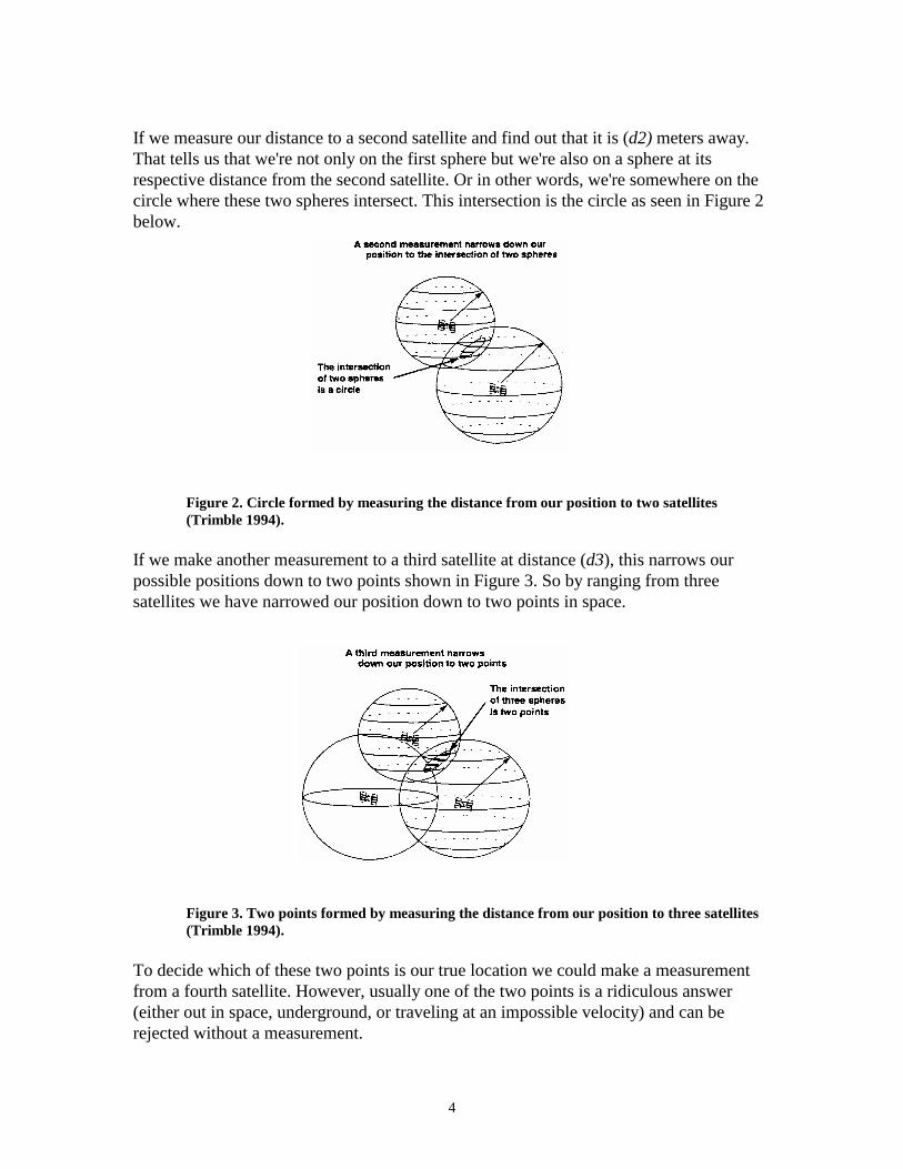
If we measure our distance to a second satellite and find out that it is (d2) meters away.That tells us that we're not only on the first sphere but we're also on a sphere at itsrespective distance from the second satellite. Or in other words, we're somewhere on thecircle where these two spheres intersect. This intersection is the circle as seen in Figure 2below.
Figure 2. Circle formed by measuring the distance from our position to two satellites(Trimble 1994).
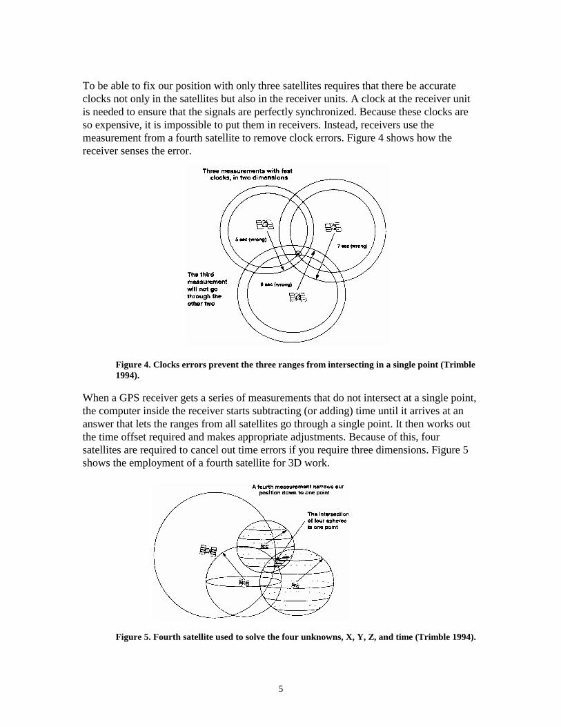
If we make another measurement to a third satellite at distance (d3), this narrows ourpossible positions down to two points shown in Figure 3. So by ranging from threesatellites we have narrowed our position down to two points in space.
Figure 3. Two points formed by measuring the distance from our position to three satellites(Trimble 1994).
To decide which of these two points is our true location we could make a measurementfrom a fourth satellite. However, usually one of the two points is a ridiculous answer(either out in space, underground, or traveling at an impossible velocity) and can berejected without a measurement.
5
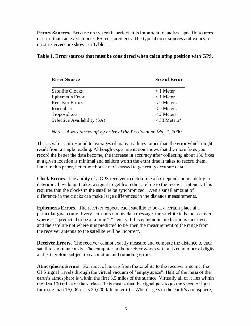
To be able to fix our position with only three satellites requires that there be accurateclocks not only in the satellites but also in the receiver units. A clock at the receiver unitis needed to ensure that the signals are perfectly synchronized. Because these clocks areso expensive, it is impossible to put them in receivers. Instead, receivers use themeasurement from a fourth satellite to remove clock errors. Figure 4 shows how thereceiver senses the error.
Figure 4. Clocks errors prevent the three ranges from intersecting in a single point (Trimble1994).
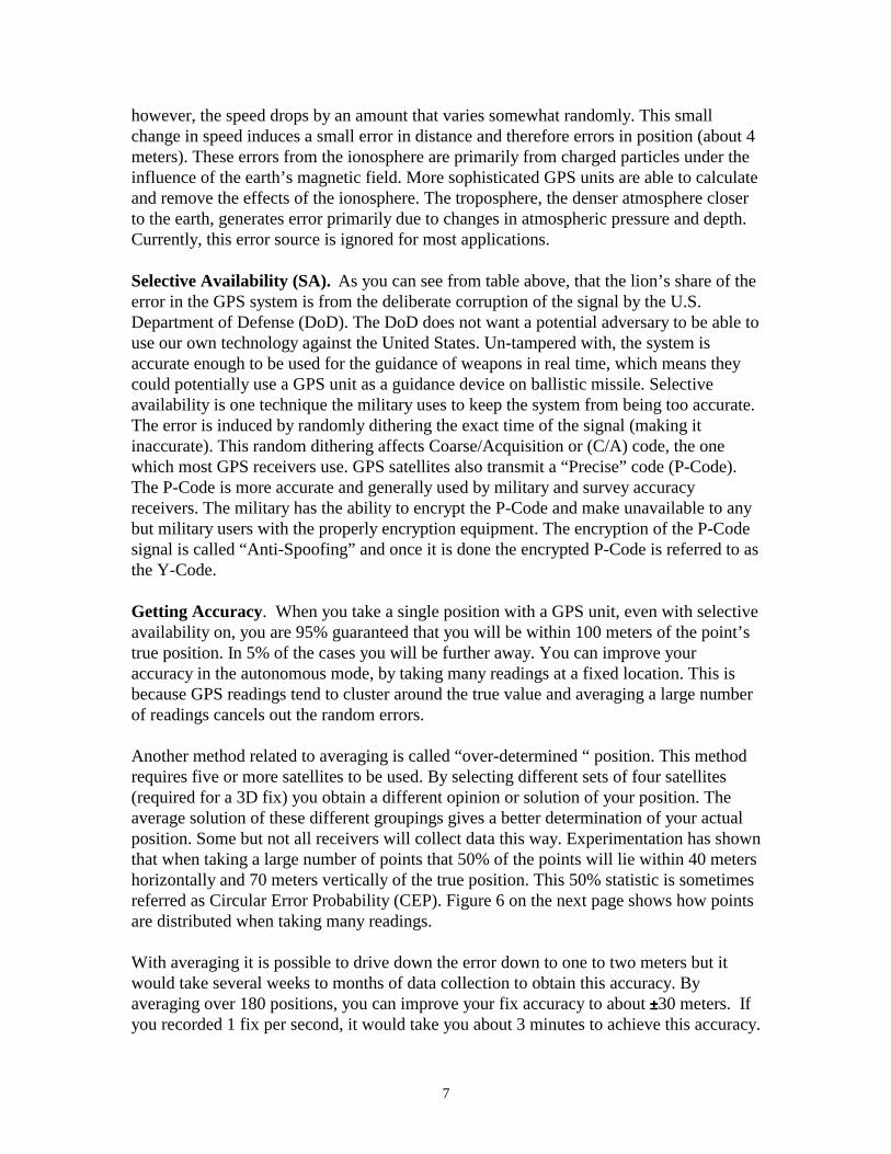
When a GPS receiver gets a series of measurements that do not intersect at a single point,the computer inside the receiver starts subtracting (or adding) time until it arrives at ananswer that lets the ranges from all satellites go through a single point. It then works outthe time offset required and makes appropriate adjustments. Because of this, foursatellites are required to cancel out time errors if you require three dimensions. Figure 5shows the employment of a fourth satellite for 3D work.
Figure 5. Fourth satellite used to solve the four unknowns, X, Y, Z, and time (Trimble 1994).
6
Errors Sources. Because no system is perfect, it is important to analyze specific sourcesof error that can exist in our GPS measurements. The typical error sources and values formost receivers are shown in Table 1.
Table 1. Error sources that must be considered when calculating position with GPS.
______________________________________________________
Error Source Size of Error______________________________________________________Satellite Clocks < 1 MeterEphemeris Error < 1 MeterReceiver Errors < 2 MetersIonosphere < 2 MetersTroposphere < 2 MetersSelective Availability (SA) < 33 Meters*______________________________________________________Note: SA was turned off by order of the President on May 1, 2000.
Theses values correspond to averages of many readings rather than the error which mightresult from a single reading. Although experimentation shows that the more fixes yourecord the better the data become, the increase in accuracy after collecting about 180 fixesat a given location is minimal and seldom worth the extra time it takes to record them.Later in this paper, better methods are discussed to get really accurate data.
Clock Errors. The ability of a GPS receiver to determine a fix depends on its ability todetermine how long it takes a signal to get from the satellite to the receiver antenna. Thisrequires that the clocks in the satellite be synchronized. Even a small amount ofdifference in the clocks can make large differences in the distance measurements.
Ephemeris Errors. The receiver expects each satellite to be at a certain place at aparticular given time. Every hour or so, in its data message, the satellite tells the receiverwhere it is predicted to be at a time “t” hence. If this ephemeris prediction is incorrect,and the satellite not where it is predicted to be, then the measurement of the range fromthe receiver antenna to the satellite will be incorrect.
Receiver Errors. The receiver cannot exactly measure and compute the distance to eachsatellite simultaneously. The computer in the receiver works with a fixed number of digitsand is therefore subject to calculation and rounding errors.
Atmospheric Errors. For most of its trip from the satellite to the receiver antenna, theGPS signal travels through the virtual vacuum of “empty space”. Half of the mass of theearth’s atmosphere is within the first 3.5 miles of the surface. Virtually all of it lies withinthe first 100 miles of the surface. This means that the signal gets to go the speed of lightfor more than 19,000 of its 20,000 kilometer trip. When it gets to the earth’s atmosphere,
7
however, the speed drops by an amount that varies somewhat randomly. This smallchange in speed induces a small error in distance and therefore errors in position (about 4meters). These errors from the ionosphere are primarily from charged particles under theinfluence of the earth’s magnetic field. More sophisticated GPS units are able to calculateand remove the effects of the ionosphere. The troposphere, the denser atmosphere closerto the earth, generates error primarily due to changes in atmospheric pressure and depth.Currently, this error source is ignored for most applications.
Selective Availability (SA). As you can see from table above, that the lion’s share of theerror in the GPS system is from the deliberate corruption of the signal by the U.S.Department of Defense (DoD). The DoD does not want a potential adversary to be able touse our own technology against the United States. Un-tampered with, the system isaccurate enough to be used for the guidance of weapons in real time, which means theycould potentially use a GPS unit as a guidance device on ballistic missile. Selectiveavailability is one technique the military uses to keep the system from being too accurate.The error is induced by randomly dithering the exact time of the signal (making itinaccurate). This random dithering affects Coarse/Acquisition or (C/A) code, the onewhich most GPS receivers use. GPS satellites also transmit a “Precise” code (P-Code).The P-Code is more accurate and generally used by military and survey accuracyreceivers. The military has the ability to encrypt the P-Code and make unavailable to anybut military users with the properly encryption equipment. The encryption of the P-Codesignal is called “Anti-Spoofing” and once it is done the encrypted P-Code is referred to asthe Y-Code.
Getting Accuracy. When you take a single position with a GPS unit, even with selectiveavailability on, you are 95% guaranteed that you will be within 100 meters of the point’strue position. In 5% of the cases you will be further away. You can improve youraccuracy in the autonomous mode, by taking many readings at a fixed location. This isbecause GPS readings tend to cluster around the true value and averaging a large numberof readings cancels out the random errors.
Another method related to averaging is called “over-determined “ position. This methodrequires five or more satellites to be used. By selecting different sets of four satellites(required for a 3D fix) you obtain a different opinion or solution of your position. Theaverage solution of these different groupings gives a better determination of your actualposition. Some but not all receivers will collect data this way. Experimentation has shownthat when taking a large number of points that 50% of the points will lie within 40 metershorizontally and 70 meters vertically of the true position. This 50% statistic is sometimesreferred as Circular Error Probability (CEP). Figure 6 on the next page shows how pointsare distributed when taking many readings.
With averaging it is possible to drive down the error down to one to two meters but itwould take several weeks to months of data collection to obtain this accuracy. Byaveraging over 180 positions, you can improve your fix accuracy to about ±±±±30 meters. Ifyou recorded 1 fix per second, it would take you about 3 minutes to achieve this accuracy.

8
There are other methods like differential correction that allow you to collect very accuratepoints very quickly.

9
Figure 6. CEP scatter for positions for 100 fixes (Trimble 1994).
10
1.3 The GPS Network
Satellites
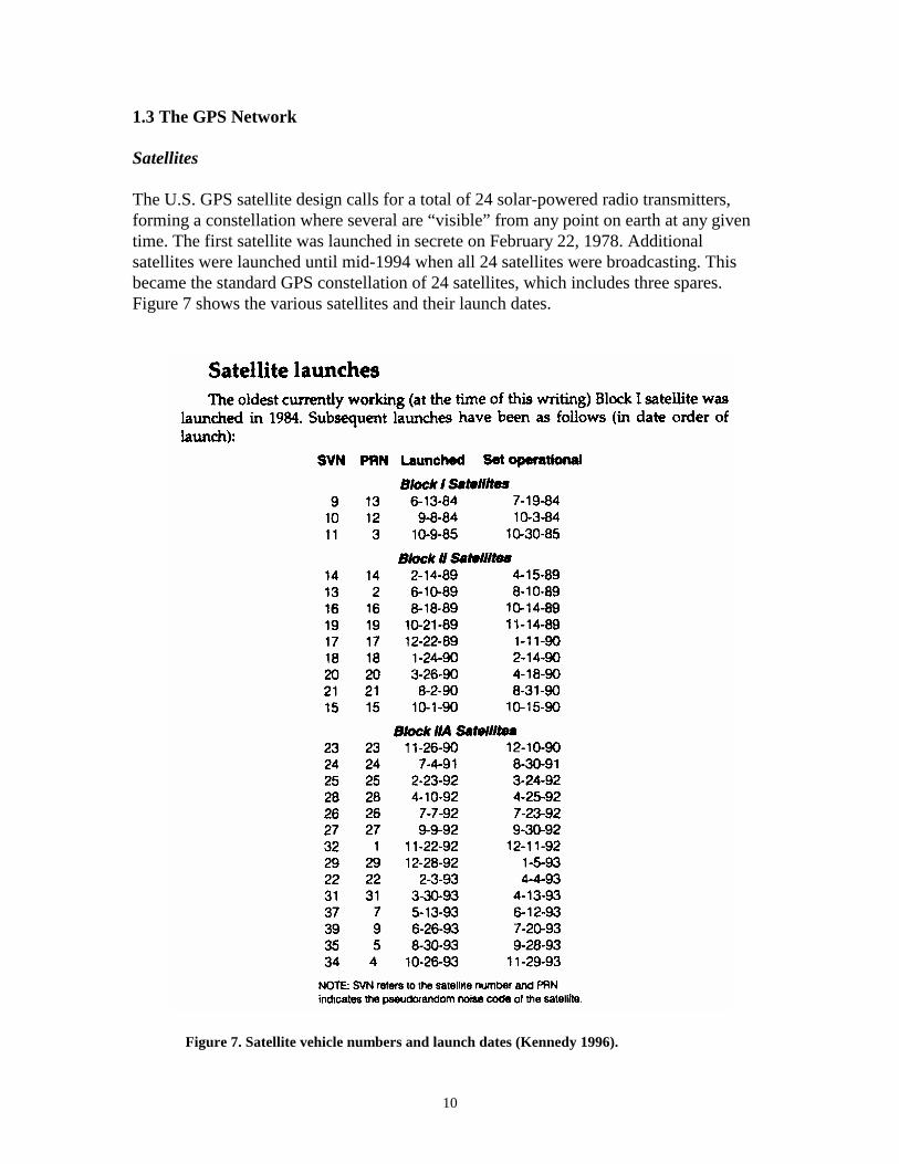
The U.S. GPS satellite design calls for a total of 24 solar-powered radio transmitters,forming a constellation where several are “visible” from any point on earth at any giventime. The first satellite was launched in secrete on February 22, 1978. Additionalsatellites were launched until mid-1994 when all 24 satellites were broadcasting. Thisbecame the standard GPS constellation of 24 satellites, which includes three spares.Figure 7 shows the various satellites and their launch dates.
Figure 7. Satellite vehicle numbers and launch dates (Kennedy 1996).
11
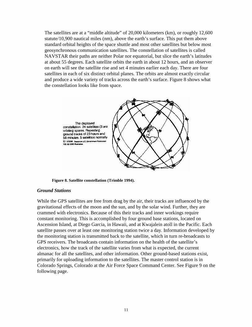
The satellites are at a “middle altitude” of 20,000 kilometers (km), or roughly 12,600statute/10,900 nautical miles (nm), above the earth’s surface. This put them abovestandard orbital heights of the space shuttle and most other satellites but below mostgeosynchronous communication satellites. The constellation of satellites is calledNAVSTAR their paths are neither Polar nor equatorial, but slice the earth’s latitudesat about 55 degrees. Each satellite orbits the earth in about 12 hours, and an observeron earth will see the satellite rise and set 4 minutes earlier each day. There are foursatellites in each of six distinct orbital planes. The orbits are almost exactly circularand produce a wide variety of tracks across the earth’s surface. Figure 8 shows whatthe constellation looks like from space.
Figure 8. Satellite constellation (Trimble 1994).
Ground Stations
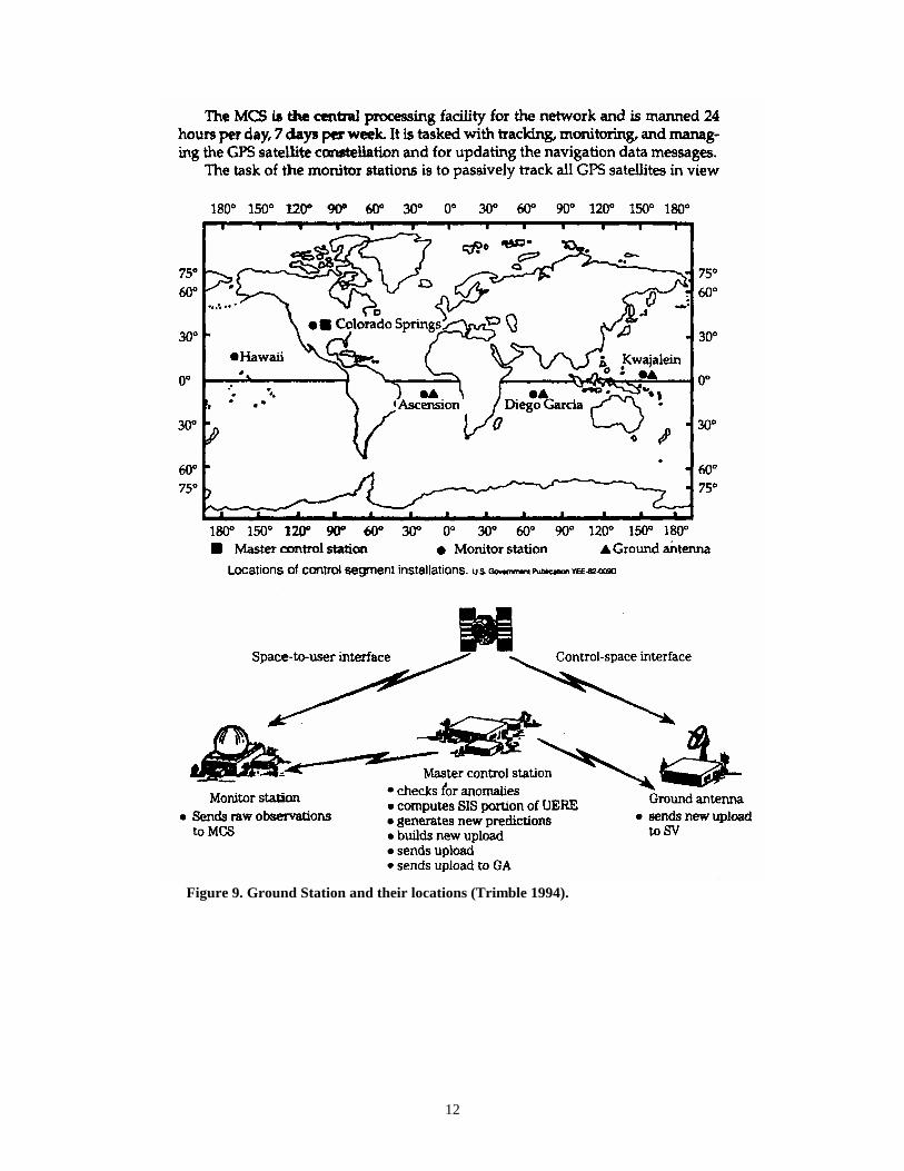
While the GPS satellites are free from drag by the air, their tracks are influenced by thegravitational effects of the moon and the sun, and by the solar wind. Further, they arecrammed with electronics. Because of this their tracks and inner workings requireconstant monitoring. This is accomplished by four ground base stations, located onAscension Island, at Diego Garcia, in Hawaii, and at Kwajalein atoll in the Pacific. Eachsatellite passes over at least one monitoring station twice a day. Information developed bythe monitoring station is transmitted back to the satellite, which in turn re-broadcasts toGPS receivers. The broadcasts contain information on the health of the satellite’selectronics, how the track of the satellite varies from what is expected, the currentalmanac for all the satellites, and other information. Other ground-based stations exist,primarily for uploading information to the satellites. The master control station is inColorado Springs, Colorado at the Air Force Space Command Center. See Figure 9 on thefollowing page.
12
Figure 9. Ground Station and their locations (Trimble 1994).

13
1.4 GPS Receiver, Modes, Methods, and Types
GPS receivers are available in a wide range of configurations and price levels. Receiversmay be purchased for as little as $99 or as much as $50,000. This range in cost is directlyrelated to the features and precision that are achievable with the given unit. Users need tobe wary of any low price unit that claim to be accurate to ±10 or better, as the advertisedprecision of a unit is often based on the best case scenario, which may or may not beachievable in the field.
The precision of a GPS receiver is determined based on the signals the receiver utilizes tocalculated its position as well as the methods and modes used while it is in operation.Please note that the precision of a unit is based on the smallest significant unit(centimeter, decimeter, meter, tens-of-meters) that the receiver is able to repeatablemeasure. The accuracy of the coordinates obtained from the receiver is a function of boththe receiver/antenna combination used and the projection, datum, and coordinate systemselected by the user (see Section 1.5). Use of an unsuitable datum, projection, orcoordinate system may degrade the accuracy of the data collected by the receiver or makeit unusable when the data are downloaded and entered into a GIS.
GPS receivers calculate location based on the radio signals received through theirantenna. The antenna should be positioned in such a way as to maximize its visibility tothe open sky, as GPS signals will not penetrate vegetation, metal roofs or human bodies!Note that the position calculated by the receiver is actually the phase-center of theantenna, not the location of the receiver. As such, the GPS antenna should be placed on orover the position to be surveyed and the offset between the antenna and the known object(e.g., the antenna is on a 2.00 meter “range pole” and the tip of the range pole was set ontop of the well head cover). By keeping track of these offsets, the GPS derived locationsmay be corrected to obtain the actual X, Y, Z, location of the point of interest.
The GPS user should be aware of the limitations inherent with the receiver/antennaconfiguration they are using, as the combination required often varies based on the type ofsurvey being conducted.
GPS Modes
An individual GPS receiver may be able to operate within several different positioningmodes. In order of precision these modes are autonomous, differential, kinematic, andstatic.
Autonomous positioning is a mode of operation of a GPS receiver where the receivercalculates position in real-time from satellite data alone without reference to data suppliedfrom another receiver that is located at a fixed, known, location (i.e., base station). This isthe least precise mode of operation. Point coordinate accuracy of ±100 m RMS isobtainable when selective availability is in effect and ±10 m when it is not.
14
Differential positioning is a mode of GPS surveying that uses two or more receivers withone receiver acting as a base station that is located at a known, fixed location and theother receiver roving to unknown points. The base station computes corrections based onthe differences between its known location and its location as computed from the satelliteC/A code. These corrections are applied to positions collected by the roving unit. Thiscorrection can be done in real-time via a radio link or during post processing back in theoffice. Point coordinate accuracy of ±30 m RMS is obtainable when selective availabilityis in effect and ±1 m when it is not.
Kinematic positioning is a mode of GPS surveying that uses two or more receivers withone receiver acting as a base station that is located at a known, fixed location and theother receiver roving to unknown points. The receivers use the L1/L2 carrier-phaseobservation (including both the C/A code and P-code) and requires short (1 second to 10minute) occupation times at the locations being visited by the roving GPS receiver. Thismethod uses baselines to calculate position and has the potential to obtain greateraccuracy than is possible with differential positioning methods. Point coordinate accuracyof ±1 m RMS is obtainable when selective availability is in effect and ±0.02 m when it isnot.
Static positioning (a.k.a., geodetic survey) is a mode of GPS surveying that uses two ormore receivers. The receivers monitor the L1/L2 carrier-phase observations (includingboth the C/A code and P-code) and use long occupation times (> 20 minutes). Thismethod uses baselines to calculate position and has the potential to obtain greateraccuracy than is possible with differential and kinematic positioning methods. Location isdetermination when the receiver's antenna is stationary on the earth. Point coordinateaccuracy of ±0.05 m RMS is obtainable when selective availability is in effect and betterthan ±0.01 m when it is not. At least three of the points visited during the survey shouldhave known horizontal and vertical position. These known points are held fixed whencalculating the baselines and insure that the newly surveyed points are tied into the localgeodetic control network.
GPS Methods
The three methods used by GPS receivers to obtain position information are autonomous,post processed, and real-time. The autonomous method occurs when the GPS receiver isused as a stand-alone data collector and no further processing of the data will be done onreturn to the office. The location information collected is transcribed onto paper in thefield or stored in the GPS unit for later transfer in the office to a database for mappingpurposes. This method is the simplest and the least accurate of the three methods.
The post processing method is used when the GPS receiver is used as a data collector andfurther processing of the position data will be completed after down loading the data atthe office. This method assumes that a base station receiver (located at a known, fixed,position) was collecting data simultaneously with the roving unit. Based on the types of

15
receivers and antennas used during the survey and the positioning data collected either thedifferential, kinematic, or static processing mode may be used.
The real-time method occurs when the GPS receiver is used as a data collector and thepositions obtained are corrected on-the-fly based on information received via radio signalreceived from a base station (located at a known, fixed, position). Based on the types ofreceivers and antennas used during the survey either the differential or kinematic modemay be used.
GPS Receiver Types
As the previous description of positioning methods and modes may have indicated, boththe receiver and antenna directly impact the precision to which one may survey. Forexample, the Coastal Monitoring and Analysis Group within the Shorelands andEnvironmental Assistance Program currently has two Trimble 4400 survey gradereceivers. These receivers are able to track both the C/A code and P-code and monitorboth the L1 and L2 frequency of the GPS satellite signal. These receivers are used withL1/L2 Geodetic Antennas with a removable groundplain (a device that minimizes theeffects of multipath on position calculations) and a real-time radio link.
The Trimble 4400 receiver configured as the base station uses a L1/L2 antenna withgroundplain. In this configuration the base station commonly obtains a point positionprecision of ±0.01 m. When the second receiver is used as a rover (i.e., the groundplain isremoved from the antenna), and real-time kinematic positioning method is used positionsgood to ±0.05 to 0.02 m are obtained. However, if we had used an L1 Compact Antenna(often used with Trimble mapping grade receivers) on the rover instead of the L1/L2Geodetic Antenna, we would have obtained positions accurate of about ±0.5 m.
Table 2 shows in a general sense, the relative positioning accuracy that can be expectedby different receiver types when using different modes of operation. Remember that thereported accuracy is usually reported as a RMS error and that any single GPSmeasurement may vary significantly from the mean

16
Table 2. Common horizontal accuracy of different GPS receiver configurationsbased on different modes of operation. There is a 95% probability that a singlemeasurement will fall within a circle of the diameter shown (values in meters).
ModeReceiver Type Autonomous Differential Kinematic Static
Navigation UnitUsing L1 C/A Code($99 to $1,000) ±100 (10) ±30 to 10 (5) n/a n/a
Mapping UnitUsing L1 C/A and P Code($1,000 to $8,000) ±30 (5) ±10 to 1 ± 0.50 n/a
Survey Grade UnitUsing L1 C/A, L1 P, and L2 P Code($8,000 to $50,000) ± 30 (5) ±10 to 0.5 ± 0.02 ±0.001
Note: Both differential and kinematic modes may use the real-time method.Note: SA was turned off on May 1, 2000, increased accuracy is shown inparentheses.
The range of accuracy’s shown in Table 2 are controlled by two major factors, the statusof SA and anti-spoofing (on or off) and the codes and frequencies the receiver uses tocalculation position. For example, most mapping grade units only use the C/A and PCode from the L1 GPS signals to calculate position. Since they do not monitor the L2frequency these units are unable to correct for position error introduced by atmosphericdelay effects. In addition, the autonomous and differential modes of operation often usethe Course Acquisition (C/A) code to calculation position. As the name indicates, use ofthe C/A code limits the maximum obtainable precision to ±30 m in autonomous mode and±1 in differential mode.
SA was turned off by order of the President of the United States on May 1, 2000.Removal the SA “random error” from the GPS signal has increased the accuracy ofstandalone and autonomous GPS receivers by a factor of 10, improving the predictedaccuracy of GPS for civilian users from within 100 m to within 20 m. This performanceboost will enable GPS to be applied in its most basic form to a variety of civilianactivities. Figure 10 shows the impact of the removal of SA on the calculated position ofa stationary GSP receiver during the change over from with to without SA. Note that CEPstands for circle error probability (2 D coordinates) and SEP stands for spherical errorprobability (3 D coordinates).

17
Figure 10. Accuracy of GPS derived position for a stationary GPS receiver beforeand after selective availability (SA) was turned off.
1.5 Projections, Coordinate Systems, and Datum’s
The projections, datum’s, and coordinate selected for use during survey or other datacollection projects directly impact the obtainable accuracy of the final data. Every GPSuser should have a basic understanding of the projection they are using, no mater howmuch computers seem to have automated the process.
A map projection is a systematic representation of all or part of the surface of a roundbody (e.g., the Earth) on a plane. Since one can not depict a round body on a plane without distortion one must select those features of the map to be shown accurately at theexpense of others. If the region to be mapped covers a large area such as a continent thedistortion will be visually apparent. In contrast, if the area to be mapped covers a smallarea, such as a single state, distortion may be barely measurable if the correct projection isused.
There are an infinite number of projections that may be devised. Most of these projectionsare rarely used novelties that should be avoided when using GPS equipment. The mostcommonly used projections for mapping purposes are based on the Lambert ConformalConic, Transverse Mercator, or Universal Transverse Mercator (UTM) projections. Once
18
a projection has been selected a rectangular grid (e.g., Washington State Plain South orUTM zones) may be devised that allows the use of basic trigonometry functions tocalculate position (a requirement in the past for rapid, error free, mapping while in thefield).
In addition, a simple spherical coordinate systems may be devised (e.g., latitude andlongitude) and used for mapping. Note that the latitude and longitude values are notarbitrary, the values are measurements from the Earth’s center to a point on the Earth’ssurface and represent the angles of a line extending to that point. Latitude and longitudevalues are represented as degrees (360 degrees in a circle) and each degree can be dividedinto 60 minutes, and each minute into 60 seconds. Thus, the latitude and longitudecoordinates for a given point on the Earth varies based on the size of the sphere, or shapeof the ellipsoid, used to represent the Earth.
As noted above, the coordinate of a given location on the Earth, be it latitude andlongitude or Northing and Eastings, vary based on the model the Earth used. In aspherical coordinate system this model is referred to as an ellipsoid or spheroid. In arectangular grid system the model is optimized for a particular region of the world bycombining an ellipsoid and other parameters (e.g., offsets) to define a datum.
Conversion of coordinates to or from spherical reference systems and rectangular systemsthat are defined based on a mathematical ellipsoid or datum model may be done with aminimal loss of accuracy. It is this constraint that must be considered when using GPSequipment as many older datum’s, such as the North American Datum of 1927 (NAD27), are based on ellipsoids that are quite different from the one currently used by theGPS system.
The GPS system uses the World Geodetic System of 1984 (WGS 84) as its standarddatum. The North American Datum of 1983 (NAD 83) is used for precise horizontalpositioning within North American and other near-by areas. The ellipsoid used by NAD83, Global Reference System of 1980 (GRS 80), is nearly identical to WGS 84. Sinceboth of these two datums are defined based on precise mathematical model of the Earth,direct conversion between the two is possible.
The previous discussion of datums was predominantly concerned with horizontalcoordinates systems. When one needs elevations tied to a vertical datum in the UnitedStates other issues arise. In the U.S. there are three commonly used vertical datums, MeanLower Low Water (MLLW) as defined by a tide gauge, Mean Sea Level (MSL) orNational Geodetic Vertical Datum of 1929 (NGVD 29), and the North American VerticalDatum of 1988 (NAVD 88). Of these only NAVD 88 is directly supported by GPS.
Why is this? Recall that GPS obtains positions in the WGS 84 datum. This datumsupports horizontal and vertical coordinates, where the vertical coordinate is representedas a distance from the center of the Earth. This value is often converted based on a geoidmodel (a model of a surface of constant gravitational pull, specifically the one that most

19
closely coincides with mean sea level over the entire surface of the earth) to a value moreclosely resembling a traditional elevation.
The conversion between the WGS 84 datum and a local coordinate system, such asWashington State Plain South, NAD 83, involves several steps (Figure 2). Each step is awell-defined mathematical process that depends on a known set of parameters that areused to convert the GPS coordinates into coordinates in the projection needed. Many GPSreceivers allow many of these transformations to be done on-the-fly by the softwareloaded in the data collector.
Figure 11. Converting between WGS 84 and a local map grid such asWashington State Plain South NAD 83 (Trimble 1996).
The current geoid model, known as GEOID 99, developed by the National GeodeticSurvey (http://www.ngs.noaa.gov) supports the direct conversion of GPS elevations intoNAVD 88. Note that the conversion to NGVD 29 is not support by the National GeodeticSurvey. Thus, to obtain an estimated elevation in NGVD 29 (MSL) or a MLLW datumrequires that the user to obtain a GPS measurement at a reference station with a knownelevation in the older datum and that the offset or correction be determine. The calculatedcorrection may then be apply to other GPS derived NAVD 88 elevations to obtain anelevation expressed in the older datum. Such a correction is only valid near the observedbenchmark or reference station (< 50 km).

20
1.6 Standard Practices and Guidelines
The goal of this document is not to dictate the type or model of GPS receiver purchasedby a particular group within Ecology. Instead this document is designed to provide a basiclevel of information that all GPS users should know and consider when designing aparticular GPS survey or data collection effort. Failure to consider the factors describedhere may result in the loss of valuable data or the collection of data that does not meet thestated need of the project.
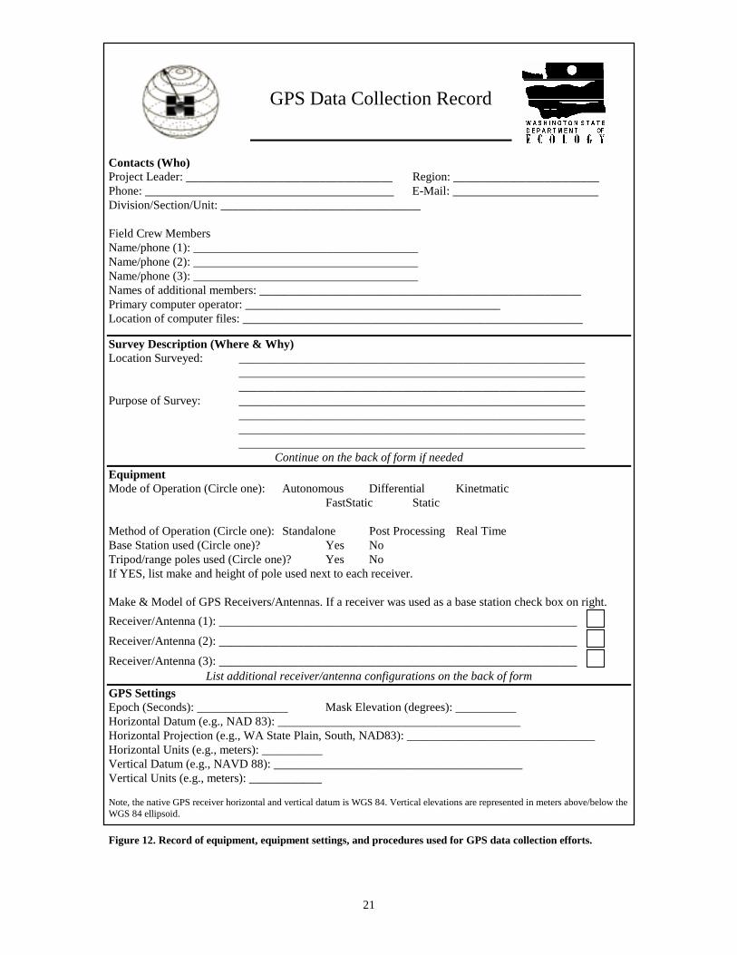
To assist the user in identifying the inherent limitations associated with their equipmentand in documenting the settings used during a particular data collection effort Figure 12has been prepared. When completed this form provides a record of the equipment typesused and how it was configured for a particular survey. This information is the minimuminformation that a third party (e.g., your GIS Analyst or the person doing your PostProcessing) will need to convert the raw GPS data to meaningful information.
21
GPS Data Collection Record
Contacts (Who)Project Leader: __________________________________ Region: ________________________Phone: _________________________________________ E-Mail: ________________________Division/Section/Unit: _________________________________
Field Crew MembersName/phone (1): _____________________________________Name/phone (2): _____________________________________Name/phone (3): _____________________________________Names of additional members: _____________________________________________________Primary computer operator: __________________________________________Location of computer files: ________________________________________________________
Survey Description (Where & Why)Location Surveyed: _________________________________________________________
__________________________________________________________________________________________________________________
Purpose of Survey: ____________________________________________________________________________________________________________________________________________________________________________________________________________________________________
Continue on the back of form if neededEquipmentMode of Operation (Circle one): Autonomous Differential Kinetmatic
FastStatic Static
Method of Operation (Circle one): Standalone Post Processing Real TimeBase Station used (Circle one)? Yes NoTripod/range poles used (Circle one)? Yes NoIf YES, list make and height of pole used next to each receiver.
Make & Model of GPS Receivers/Antennas. If a receiver was used as a base station check box on right.Receiver/Antenna (1): ___________________________________________________________
Receiver/Antenna (2): ___________________________________________________________
Receiver/Antenna (3): ___________________________________________________________List additional receiver/antenna configurations on the back of form
GPS SettingsEpoch (Seconds): _______________ Mask Elevation (degrees): __________Horizontal Datum (e.g., NAD 83): ________________________________________Horizontal Projection (e.g., WA State Plain, South, NAD83): _______________________________Horizontal Units (e.g., meters): __________Vertical Datum (e.g., NAVD 88): _________________________________________Vertical Units (e.g., meters): ____________
Note, the native GPS receiver horizontal and vertical datum is WGS 84. Vertical elevations are represented in meters above/below theWGS 84 ellipsoid.
Figure 12. Record of equipment, equipment settings, and procedures used for GPS data collection efforts.
22
1.7 References
Daniels, R. C., P. Ruggiero, and L. Weber. 1999. Washington Coastal Geodetic ControlNetwork: Report and Station Index Developed in Support of the Southwest WashingtonCoastal Erosion Study. Publication No. 99-103, Coastal Monitoring & Analysis Program,Washington Department of Ecology, Olympia, WA.
Department of Licensing. 1998. The Law Relating to Engineers and Land Surveyors.RCSC-651-001, Washington Department of Licensing, Olympia, WA.
Trimble. 1996. GPS Surveying General Reference. Part Number 25748-20, Revision A,Trimble Navigation Limited. Sunnyvale, CA.
Trimble. 1994. Mapping Systems General Reference. Part Number 24177-00, Revision A,Trimble Navigation Limited. Sunnyvale, CA.
Kennedy, M. 1996. The Global Positioning System and GIS. Ann Arbor Press, Chelsea,MI.
Zilkoski, D.B., J. D. D’Onofrio, and S. J. Frakes. 1997. Guidelines for Establishing GPS-Derived Ellipsoid Heights (Standards 2 cm and 5 cm), Version 4.3. NOAA TechnicalMemorandum NOS NGS-58, National Geodetic Survey, Silver Spring, MA.
23
SECTION 2: SURVEY NETWORKS
2.1 What is a Network?
What is a “network” and why do I need one? This question is often asked by new GPSusers. To begin with, the new GPS users needs to realize that when they are collectingpoints or lines on the ground they are performing a survey. With this realization oneshould ask how will this data be connected or related to the real world. For projects whereaccuracy’s of ±30 m or less are suitable, the “network” is actually formed by theconstellation of satellites that are in view during the survey. These satellites provided“control” to the survey by transmitting radio signals that are received by the GPS receiveron the ground. The receiver computed the distance to each satellite and via triangulationis able to determine its location on the Earth.
For data collection projects (surveys) with more stringent accuracy requirements, e.g.,±10.0 to 0.5 m, an additional point of reference is added to our “network”. This additionis the location of the base station. The base station may be a GPS receiver that you setupand operate during the survey or may be a receiver owned by a third party (e.g., U.S.Coast Guard, King County, etc.). In either case, the base station is assumed to be locatedat known position. The data collected by the base may be stored for later retrieval (for apost-processed survey) or may be transmitted over radio to the user in the field (for a realtime survey).
Surveys that require an accuracy of ±0.50 to 0.02 m need additional control (Zilkoski etal. 1997). This control is obtained by visiting locations in the field during the survey thathave known coordinates (of similar quality to the base station). These points are surveyedfor a few seconds to several minutes and are used to calibrate the project. Calibration isthe process where software in the receiver further constrains the results of the correctionprovided by the base station to obtain sub-decimeter accuracy levels.
Thus, to be able to conduct surveys of relatively high accuracy one needs to have anetwork of survey stations with known coordinates distributed throughout the projectarea. The development of such a network is a time-consuming process (e.g. Daniels et al.1999). Fortunately, the National Geodetic Survey, U.S. Corps of Engineers, WashingtonState Department of Transportation, and many county and city governments have developtheir networks to support ongoing operations. By taking advantage of these networks oneshould be able to perform sub-meter surveys almost any location within the state ofWashington.

24
2.2 Survey Station PARK
To support the increasing use of GPS within Ecology, the Shorelands and EnvironmentalAssistance Program (Coastal Monitoring and Analysis Program) has installed andsurveyed a control station at the Ecology Headquarters building in Lacey, Washington.This survey station was installed to provide a fixed reference point with knowncoordinates at Ecology. This control point may be used in three ways,
1. as a base station site during surveys within the area (~100 km ),2. as a control point for use during training of new GPS field personnel,3. as a reference point to which the coordinates obtained by less expensive mapping and
navigation grade receivers may be compared.
The coordinates derived by Ecology for station PARK were obtained using the staticobservation method and followed NGS guidelines (Zilkoski et al. 1997). During thesurvey six, forty-five minute GPS sessions were conducted using Trimble 4400 seriesGPS receivers. The receivers were setup over stations PARK (at Ecology), Q 13, HOSPRM 4, and A 461.
Stations Q 13 (PID SY0708), A 461 RESET 2 (PID SY1600), and HOSP RM 4 (PIDSY3193) were installed by the NGS and provided the control for the survey and the ties tothe national geodetic network. Station Q 13 served as the primary control for this survey.Q 13 had been resurveyed in 1998 by the NGS as part of observations conducted for theWashington High Accuracy Reference Network (HARN). The coordinates of Q 13 wereheld fixed during the final adjustment as the station had both a first order verticalelevation and a B order horizontal coordinate (the horizontal order, or accuracy, of astation may range from AA, A, B, 1, 2, 3 -with AA being the best). Stations HOSP RM 4and A 461 provided additional secondary control to the survey.
The baselines obtained by this survey agreed to within ±0.011 m over a distance of 3,821m from station Q 13 to PARK, to within ±0.006 m over a distance of 6,196 m fromstation A 461 to PARK, and to ±0.015 m over a distance of 3,821 m from station HOSPRM 4 to PARK.

25
2.3 Observation Plan for Station PARK
The new survey mark, PARK, is located in Lacey, Washington. The mark is a four footstainless steel rod mark set flush with the ground with an aluminum logo cap stampedPARK 2000. The station is being surveyed to provide local control for use by Ecologypersonnel during training and as a base station site during GPS work within 50 miles ofthe Ecology HQ building.
The following ties will be made to obtain a GPS ellipsoid elevation, NAVD 88 height,and second order horizontal coordinates for the new station. UTC date for paper work andjob names: UTC on 27 March is 087. UTC time is +8 hours from Pacific Standard Time.
27 March 2000Session Receiver Station Type Time101 R1 Q 13 Primary 1310 to 1425
R2 PARK New Station
102 R1 HOSP RM 4 Secondary 1450 to 1535R2 PARK New Station
103 R1 A 461 RESET 2 Secondary 1615 to 1705R2 PARK New Station
28 March 2000Session Receiver Station Type Time201 R1 Q 13 Primary 0945 to 1030
R2 PARK New Station
202 R1 HOSP RM 4 Secondary 1100 to 1145R2 PARK New Station
203 R1 A 461 RESET 2 Secondary 1215 to 1300R2 PARK New Station
Note: sessions are 45 minute sessions with 5 second epoch intervals, 15 degree masks,and QA 1 and 2 on.
EquipmentR1 Tripod: Sakko, 2m fixed, HT + PCO = 205.6455 cm
Antenna: Trimble L1/L2 Compact W/Groundplain, PN 220220-00, SN 0220079730Receiver: Trimble 4400, PN 29887-11, SN 3652A18127
R2 Tripod: Omni, 2m fixed, HT + PCO = 204.2625 cmAntenna: Trimble L1/L2 Compact W/Groundplain, PN 220220-00, SN 0220079600Receiver Trimble 4400, PN 29887-11, SN 3652A18099
26
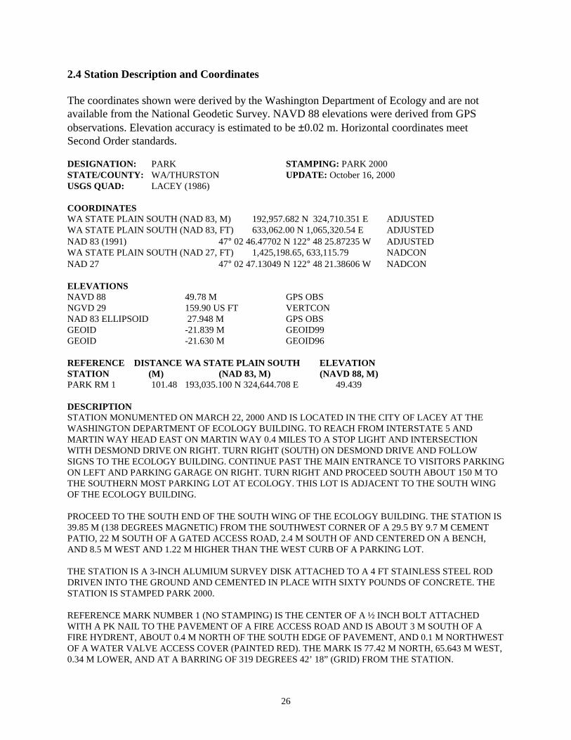
2.4 Station Description and Coordinates
The coordinates shown were derived by the Washington Department of Ecology and are notavailable from the National Geodetic Survey. NAVD 88 elevations were derived from GPSobservations. Elevation accuracy is estimated to be ±0.02 m. Horizontal coordinates meetSecond Order standards.
DESIGNATION: PARK STAMPING: PARK 2000STATE/COUNTY: WA/THURSTON UPDATE: October 16, 2000USGS QUAD: LACEY (1986)
COORDINATESWA STATE PLAIN SOUTH (NAD 83, M) 192,957.682 N 324,710.351 E ADJUSTEDWA STATE PLAIN SOUTH (NAD 83, FT) 633,062.00 N 1,065,320.54 E ADJUSTEDNAD 83 (1991) 47° 02 46.47702 N 122° 48 25.87235 W ADJUSTEDWA STATE PLAIN SOUTH (NAD 27, FT) 1,425,198.65, 633,115.79 NADCONNAD 27 47° 02 47.13049 N 122° 48 21.38606 W NADCON
ELEVATIONSNAVD 88 49.78 M GPS OBSNGVD 29 159.90 US FT VERTCONNAD 83 ELLIPSOID 27.948 M GPS OBSGEOID -21.839 M GEOID99GEOID -21.630 M GEOID96
REFERENCE DISTANCE WA STATE PLAIN SOUTH ELEVATIONSTATION (M) (NAD 83, M) (NAVD 88, M)PARK RM 1 101.48 193,035.100 N 324,644.708 E 49.439
DESCRIPTIONSTATION MONUMENTED ON MARCH 22, 2000 AND IS LOCATED IN THE CITY OF LACEY AT THEWASHINGTON DEPARTMENT OF ECOLOGY BUILDING. TO REACH FROM INTERSTATE 5 ANDMARTIN WAY HEAD EAST ON MARTIN WAY 0.4 MILES TO A STOP LIGHT AND INTERSECTIONWITH DESMOND DRIVE ON RIGHT. TURN RIGHT (SOUTH) ON DESMOND DRIVE AND FOLLOWSIGNS TO THE ECOLOGY BUILDING. CONTINUE PAST THE MAIN ENTRANCE TO VISITORS PARKINGON LEFT AND PARKING GARAGE ON RIGHT. TURN RIGHT AND PROCEED SOUTH ABOUT 150 M TOTHE SOUTHERN MOST PARKING LOT AT ECOLOGY. THIS LOT IS ADJACENT TO THE SOUTH WINGOF THE ECOLOGY BUILDING.
PROCEED TO THE SOUTH END OF THE SOUTH WING OF THE ECOLOGY BUILDING. THE STATION IS39.85 M (138 DEGREES MAGNETIC) FROM THE SOUTHWEST CORNER OF A 29.5 BY 9.7 M CEMENTPATIO, 22 M SOUTH OF A GATED ACCESS ROAD, 2.4 M SOUTH OF AND CENTERED ON A BENCH,AND 8.5 M WEST AND 1.22 M HIGHER THAN THE WEST CURB OF A PARKING LOT.
THE STATION IS A 3-INCH ALUMIUM SURVEY DISK ATTACHED TO A 4 FT STAINLESS STEEL RODDRIVEN INTO THE GROUND AND CEMENTED IN PLACE WITH SIXTY POUNDS OF CONCRETE. THESTATION IS STAMPED PARK 2000.
REFERENCE MARK NUMBER 1 (NO STAMPING) IS THE CENTER OF A ½ INCH BOLT ATTACHEDWITH A PK NAIL TO THE PAVEMENT OF A FIRE ACCESS ROAD AND IS ABOUT 3 M SOUTH OF AFIRE HYDRENT, ABOUT 0.4 M NORTH OF THE SOUTH EDGE OF PAVEMENT, AND 0.1 M NORTHWESTOF A WATER VALVE ACCESS COVER (PAINTED RED). THE MARK IS 77.42 M NORTH, 65.643 M WEST,0.34 M LOWER, AND AT A BARRING OF 319 DEGREES 42’ 18” (GRID) FROM THE STATION.

27
SECTION 3. THE LAW RELATING TO LAND SURVEYORS
Several state laws and administrative codes apply to the practice of land surveying andengineering in the State of Washington (Department of Licensing 1998). It is important tobe aware that these laws exist and that they may have an impact on the how you define,perform, and document a survey or data collection activity. This section contains extractsfrom several regulations and codes that may apply directly to you as a state employee.Additional information on the laws and codes that cover the practice of surveying may beobtained by consulting the complete text of the laws and administrative codes listed in thefollowing table.
Table 3. Laws and administrative codes of the State of Washington concerning thepractice of Land Survey and Engineering.
Law or Administrative Code Description
State LawChapter 18.43 RCW Engineers and Land SurveyorsChapter 38.80 RCW Contracts for Architectural and Engineering ServicesChapter 58.04 RCW BoundariesChapter 58.09 RCW Surveys – Recording
Administrative CodeChapter 332-130 WAC Surveys and Land DescriptionsChapter 196-09 WAC Practice and ProcedureChapter 196-12 WAC Registered Professional EngineersChapter 196-16 WAC Registered Professional Land SurveyorsChapter 196-20 WAC Engineers-in-TrainingChapter 196-21 WAC Land Surveyors-in-TrainingChapter 196-24 WAC GeneralChapter 196-25 WAC Business PracticesChapter 196-26 WAC Engineers and Surveyors - FeesChapter 196-27 WAC Rules of Professional Conduct
The practice of land survey is a regulated and licensed profession within the State ofWashington. As such it is “unlawful for any person to practice or to offer to practice …land surveying, as defined in the provisions of this chapter, or to use in connection withhis name or otherwise assume, use, or advertise any title or description tending to conveythe impression that he is a professional engineer or a land surveyor, unless such a personhas been duly registered under the provisions of this chapter” (RCW 18.43.010).
RCW 18.43.020 goes on to state that a Registered Land Surveyor must be the approvingauthority or supervise any work that deals with the “surveying of land for the

28
establishment of corners, lines, boundaries, and monuments, the laying out andsubdivision of land, the defining and locating of corners, lines, boundaries, andmonuments of land after they have been established, the survey of land areas for thepurpose of determining the topography thereof, the making of topographical delineation’sand the preparing of maps and accurate records thereof, when the proper performance ofsuch services requires technical knowledge and skill.”
The complete text of RCW 18.43 makes it clear that only Registered Land Surveyors maycertify the accuracy and correctness of land surveys that are recorded as legal documents(i.e., a record of survey). In addition, individuals performing land surveys must besupervised by a Registered Land Surveyor. This fact may lead one to believe that aRegistered Land Surveyor must be involved in all survey type work.
Fortunately for us this is the not case. RCW 58.09.090 exempts many of the commonsurvey or mapping tasks that would be conducted by a public employee from thisregulation. Specifically, RCW 58.09.090 states that a record of survey is not required(and thus a Registered Land Surveyor) “when it (the survey) has been made by a publicofficer in his official capacity and a reproducible copy thereof has been filed with thecounty engineer of the county in which the land is located” the RCW goes on to state that“a state agency conducting surveys to carry out the program of the agency shall not berequired to use a land surveyor as defined by this chapter when the survey is of apreliminary nature; when a map is in preparation for recording or shall have beenrecorded in the county under the local subdivision or platting law or ordinance; when it isa retracing or resurvey of boundaries, platted lots, tracts, or parcels shown on a filed orrecorded of survey.”
When surveys are conducted by Ecology to establish geodetic control the project designshould be reviewed by the National Geodetic Survey State Advisor (currently located atthe Department of Transportation) or a Registered Land Surveyor. In addition, the projectdesign must conform to WAC 332-130-160, which states that the “datum for horizontalcontrol network(s) in Washington shall be NAD-83 (1991) as officially adjusted andpublished by the National Geodetic Survey of the United States Department ofCommerce.” The code further states that all “horizontal and vertical control work mustmeet or exceed accuracy and specification standards as published by the Federal GeodeticControl Committee in the bulletin titled Standards and Specifications for GeodeticControl Networks” for the class of control specified in the survey plan.
On the matter of setting monuments during a survey (i.e., physical marker set in theground that serves as a reference station for later surveys); RCW 58.09.120 allows apublic officer to place or install a monument. The regulation states that any ”monument… set by a public officer … shall be marked by an appropriate official designation” andshould be set in such a way that it can not be confused with those placed by a LandSurveyor. However, the placement of new monuments, “posting, and/or marking of aboundary line between two existing corner monuments constitutes the practice of landsurveying” (WAC 196-24-110) and would require the use of a Registered Land Surveyor.
29
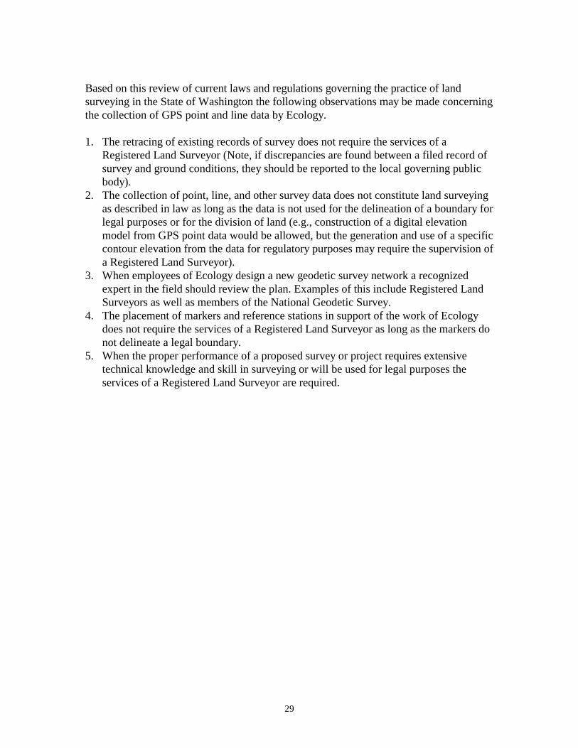
Based on this review of current laws and regulations governing the practice of landsurveying in the State of Washington the following observations may be made concerningthe collection of GPS point and line data by Ecology.
1. The retracing of existing records of survey does not require the services of aRegistered Land Surveyor (Note, if discrepancies are found between a filed record ofsurvey and ground conditions, they should be reported to the local governing publicbody).
2. The collection of point, line, and other survey data does not constitute land surveyingas described in law as long as the data is not used for the delineation of a boundary forlegal purposes or for the division of land (e.g., construction of a digital elevationmodel from GPS point data would be allowed, but the generation and use of a specificcontour elevation from the data for regulatory purposes may require the supervision ofa Registered Land Surveyor).
3. When employees of Ecology design a new geodetic survey network a recognizedexpert in the field should review the plan. Examples of this include Registered LandSurveyors as well as members of the National Geodetic Survey.
4. The placement of markers and reference stations in support of the work of Ecologydoes not require the services of a Registered Land Surveyor as long as the markers donot delineate a legal boundary.
5. When the proper performance of a proposed survey or project requires extensivetechnical knowledge and skill in surveying or will be used for legal purposes theservices of a Registered Land Surveyor are required.

30

31
SECTION 4: SURVEY/GPS TERMS AND DEFINITIONS
The following definitions were collected from several sources, the majority which wereobtained from Trimble (1994) and Trimble (1996).
AcquisitionThe process of locking onto a satellites C/A code and P-code signal. Once a receiveracquires a satellite it tracks the satellite until the signal becomes unavailable.
AlmanacInformation about GPS satellite orbits that includes clock corrections, atmospheric delayparameters, and health status of the transmitting satellite. See also ephemeris.
Altitude ReferenceThe datum used as a vertical reference for height measurements. GPS applications use theWGS-84 reference ellipsoid as the altitude reference. See also ellipsoid.
AmbiguityThe unknown integer number of cycles or wavelengths of the reconstructed carrier phasesignal contained in an unbroken set of GPS measurements (i.e., the receiver does notknow, and must estimate, the number of wavelengths between the satellite and the GPSantenna). Also known as integer ambiguity.
Anti-Spoofing (AS)A security feature that allows the U.S. Department of Defense to encrypt the P-Codetransmitted by the GPS satellites. When the P-code is encrypted it is known as the Y-Code.
Anywhere fixThe ability of a receiver to start position calculations without being given an approximatelocation and approximate time.
Autonomous PositioningA mode of operation of a GPS receiver where the receiver calculates position in real-timefrom satellite data alone without reference to data supplied from a base station. This is theleast precise mode of operation. Point coordinates accuracies of ±100 m RMS areobtainable when selective availability is in effect and ±10 when it is not.
AzimuthThe angle between a reference direction (e.g., magnetic north) and another point as seenby an observer in a specific location.
BandwidthThe range of frequencies in a signal.
32
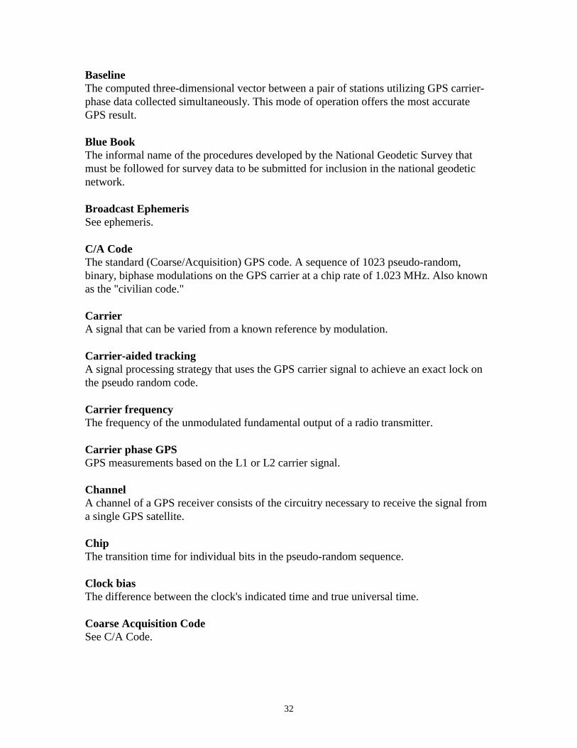
BaselineThe computed three-dimensional vector between a pair of stations utilizing GPS carrier-phase data collected simultaneously. This mode of operation offers the most accurateGPS result.
Blue BookThe informal name of the procedures developed by the National Geodetic Survey thatmust be followed for survey data to be submitted for inclusion in the national geodeticnetwork.
Broadcast EphemerisSee ephemeris.
C/A CodeThe standard (Coarse/Acquisition) GPS code. A sequence of 1023 pseudo-random,binary, biphase modulations on the GPS carrier at a chip rate of 1.023 MHz. Also knownas the "civilian code."
CarrierA signal that can be varied from a known reference by modulation.
Carrier-aided trackingA signal processing strategy that uses the GPS carrier signal to achieve an exact lock onthe pseudo random code.
Carrier frequencyThe frequency of the unmodulated fundamental output of a radio transmitter.
Carrier phase GPSGPS measurements based on the L1 or L2 carrier signal.
ChannelA channel of a GPS receiver consists of the circuitry necessary to receive the signal froma single GPS satellite.
ChipThe transition time for individual bits in the pseudo-random sequence.
Clock biasThe difference between the clock's indicated time and true universal time.
Coarse Acquisition CodeSee C/A Code.

33
Code phase GPSGPS measurements based on the pseudo random code (C/A or P) as opposed to thecarrier of that code.
ConstellationAll satellites visible to a GPS receiver at a give time.
Control segmentA worldwide network of GPS monitor and control stations that ensure the accuracy ofsatellite positions and their clocks.
Coordinate SystemAny two- or three-dimensional reference system which can be used to locate objects inspace.
CycleSee Epoch.
Cycle slipA discontinuity in the measured carrier beat phase resulting from a temporary loss of lockon a satellite in the carrier tracking loop of a GPS receiver antenna.
DatumA model of the earth consisting of an ellipsoid and an origin. GPS is based on the WGS-84 datum.
Data messageA message included in the GPS signal, which reports the satellite's location, clockcorrections and health. Included is rough information on the other satellites in theconstellation.
DGPSSee Differential Positioning.
Differential PositioningA positioning procedure that uses two or more receivers with one receiver acting as abase station that is located at a known, fixed location and the other receivers roving tounknown points. The base station computes corrections based on the differences betweenits known location and its location as computed from the satellite C/A code. Thesecorrections are applied to positions collected by the roving units. This correction can bedone in real-time via a radio link or during post processing back in the office.
Dilution of Precision (DOP)A factor that indicates the potential for ranging errors within a measurement. DOP isdetermined solely by the geometry between the user and the visible set of satellites (the
34
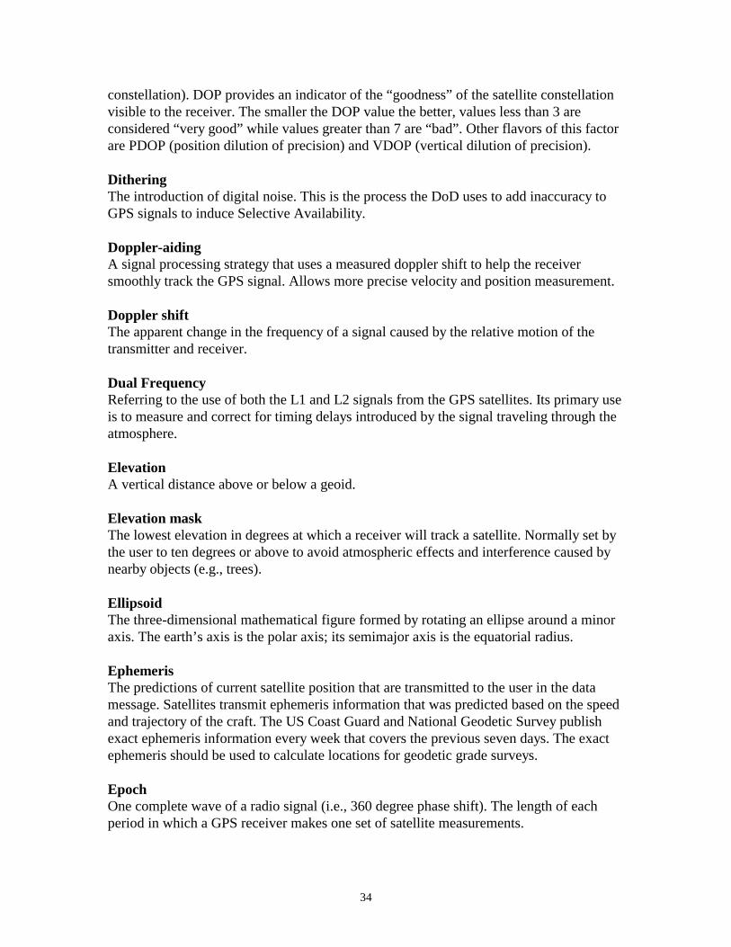
constellation). DOP provides an indicator of the “goodness” of the satellite constellationvisible to the receiver. The smaller the DOP value the better, values less than 3 areconsidered “very good” while values greater than 7 are “bad”. Other flavors of this factorare PDOP (position dilution of precision) and VDOP (vertical dilution of precision).
DitheringThe introduction of digital noise. This is the process the DoD uses to add inaccuracy toGPS signals to induce Selective Availability.
Doppler-aidingA signal processing strategy that uses a measured doppler shift to help the receiversmoothly track the GPS signal. Allows more precise velocity and position measurement.
Doppler shiftThe apparent change in the frequency of a signal caused by the relative motion of thetransmitter and receiver.
Dual FrequencyReferring to the use of both the L1 and L2 signals from the GPS satellites. Its primary useis to measure and correct for timing delays introduced by the signal traveling through theatmosphere.
ElevationA vertical distance above or below a geoid.
Elevation maskThe lowest elevation in degrees at which a receiver will track a satellite. Normally set bythe user to ten degrees or above to avoid atmospheric effects and interference caused bynearby objects (e.g., trees).
EllipsoidThe three-dimensional mathematical figure formed by rotating an ellipse around a minoraxis. The earth’s axis is the polar axis; its semimajor axis is the equatorial radius.
EphemerisThe predictions of current satellite position that are transmitted to the user in the datamessage. Satellites transmit ephemeris information that was predicted based on the speedand trajectory of the craft. The US Coast Guard and National Geodetic Survey publishexact ephemeris information every week that covers the previous seven days. The exactephemeris should be used to calculate locations for geodetic grade surveys.
EpochOne complete wave of a radio signal (i.e., 360 degree phase shift). The length of eachperiod in which a GPS receiver makes one set of satellite measurements.
35
Fast switching channelA single channel which rapidly samples a number of satellite ranges. "Fast" means thatthe switching time is sufficiently fast (2 to 5 milliseconds) to recover the data message.
Frequency bandA particular range of frequencies.
Frequency spectrumThe distribution of signal amplitudes as a function of frequency.
GeodeticOf, or concerning, the field of geodesy. Measurements that are referenced to a definedellipsoid that allow for effects of a curved earth to be corrected for when computingdirection and distance.
Geographic coordinatesA coordinate system used to locate a point on the surface of the earth. Customarilyreferred to as latitude, longitude, and the height above the ellipsoid.
GeoidA surface of constant gravitational pull that most closely coincides with mean sea levelover the surface of the earth. The geoid undulates in response to gravitational forces thataffect spirit level vials in theodolites and differential levels.
Geoid HeightThe distance between the geoid and ellipsoid at a given point.
Geometric Dilution of Precision (GDOP)See Dilution of Precision.
GMTGreenwich Mean Time (Pacific Standard Time is +8 hours). See also UTC.
GPS TimeThe time used by the GPS system based on the atomic clocks on the satellites. GPS timewas the same as UTC when the system was activated. However, variations in the rotationperiod of the earth have caused the two to diverge.
GPS WeekA period of seven days beginning and ending at 0000 hours on Sunday, GPS Time.
GRS-80Geodetic Reference System of 1980. The ellipsoid on which the North American Datumof 1983 is based. This datum has the same semimajor and semiminor axis as WGS-84(the reference ellipsoid for GPS) and differs slightly in the flattening value.
36
Hardover wordThe word in the GPS message that contains synchronization information for the transferof tracking from the C/A to P code.
Integer AmbiguitySee Ambiguity.
IonosphereThe band of charged particles 80 to 120 miles above the earth's surface.
Ionospheric refractionThe change in the propagation speed of a signal as it passes through the ionosphere.
Julian dateThe day of the year represented as a number, starting with 1 on January 1 and ending on365 (366 in leap years) on December 31.
Kinematic PositioningA method of GPS surveying which requires a base station at a fixed, known, position anduses the L1/L2 carrier-phase observables (including both the C/A code and P-code) andrequires short (1 to 10 minutes) occupation times at the unknown locations being visitedby the roving GPS receiver. This method uses baselines to calculate position and has thepotential to obtain greater accuracy than is possible with differential positioning methods.
L-bandThe group of radio frequencies extending from 390 MHz to 1550 MHz. The GPS carrierfrequencies (1227.6 MHz and 1575.42 MHz) are in the L band.
L1The primary carrier band (1575.42 MHz) used by GPS satellites to transmit data. Theband is modulated with the C/A code, P-code, and navigation message.
L2The secondary carrier band (1227.6 MHz) used by GPS satellites to satellite data. Theband is modulated with the P-code and navigation message.
Land SurveyorA person registered by the state to practice land surveying. In the state of Washington theperson is licensed under RCW 18.43.
MeterThe official unit of linear measurement for NAD-83, defined in 1983 as the lengthtraveled by light in a vacuum during 1/299,792,458 of a second.
37
Multipath errorErrors caused by the interference of a signal that has reached the receiver antenna by twoor more different paths. Usually caused by one path being bounced or reflected.
Multi-channel receiverA GPS receiver that can simultaneously track more than one satellite signal.
Multiplexing channelA channel of a GPS receiver that can be sequenced through a number of satellite signals.
Mean Sea Level (MSL)A model of the earth’s surface that represents sea level as averaged over time at specificpoints.
North American Datum of 1983 (NAD-83)A horizontal reference system based on the GRS-80 ellipsoid. This datum is used forprecise horizontal coordinates in North America and near-by countries.
North American Datum of 1927 (NAD-27)An older horizontal reference system based on the Clarke 1866 ellipsoid. This datum isused for horizontal coordinates in North America and other near-by countries. Conversionbetween WGS-84/GRS-80 and Clarke 1866 ellipsoid is not well defined and geodeticquality coordinates derived from GPS can not be obtained in NAD-27.
National Geodetic Survey (NGS)The United States National Geodetic Survey, the geodetic surveying agency of the UnitedStates Government.
ObservationA set of measurements made at a mark. One to many measurements may comprise asingle observation.
Orthometric heightThe perpendicular or vertical distance between a point on the surface of the earth andsome geoid.
P-CodeThe Precise code. A very long sequence of pseudo random binary biphase modulations onthe GPS carrier at a chip rate of 10.23 MHz which repeats about every 267 days. Eachone week segment of this code is unique to one GPS satellite and is reset each week.
PDOPSee Dilution of Precision.
38
Precise EphemerisSee Ephemeris.
Precise Positioning Service (PPS)The most accurate dynamic positioning possible with standard GPS, based on the dualfrequency P-code and no SA.
PseudoliteA ground-based differential GPS receiver which transmits a signal like that of an actualGPS satellite, and can be used for ranging and in limited visibility areas to artificiallyincrease the number of “satellites” visible to the receiver.
Pseudo random codeA signal with random noise-like properties. It is a very complicated but repeating patternof 1's and O's.
PseudorangeA distance measurement based on the correlation of a satellite transmitted code and thelocal receiver's reference code, that has not been corrected for errors in synchronizationbetween the transmitter's clock and the receiver's clock.
Satellite constellationThe arrangement in space of a set of satellites.
Selective Availability (SA)A policy adopted by the Department of Defense to introduce some intentional clock noiseinto the GPS satellite signals thereby degrading their accuracy for civilian users. SAworks by introducing controlled errors into the C/A code transmitted by the GPSsatellites. SA is not the same as anti-spoofing (AS).
Slow switching channelA sequencing GPS receiver channel that switches too slowly to allow the continuousrecovery of the data message.
Space segmentThe part of the whole GPS system that is in space, (i.e. the satellites).
Spread spectrumA system in which the transmitted signal is spread over a frequency band much widerthan the minimum bandwidth needed to transmit the information being sent. This is doneby modulating with a pseudo random code, for GPS.
Standard Positioning Service (SPS)The normal civilian positioning accuracy obtained by using the single frequency C/Acode.
39
Static PositioningA method of GPS surveying which uses multiple receivers that monitor the L1/L2 carrier-phase observables (including both the C/A code and P-code) and use long occupationtimes. This method uses baselines to calculate position and has the potential to obtaingreater accuracy that is possible with differential and kinematic positioning methods.Location is determined when the receiver's antenna is stationary on the earth. This allowsthe use of averaging techniques that improve accuracy by factors of over 1000.
User interfaceThe way a receiver conveys information to the person using it. The controls and display.
UTCUniversal Time Coordinated. Time as deduced directly from observations of stars and thefixed numerical relationship between universal and sidereal time.
US Survey FootThe official unit of linear measurement for NAD-27, defined as 39.38 inches = 1 meter(exact).
User segmentThe part of the whole GPS system that includes the receivers of GPS signals.Back to the start of the tutorial...
VDOPSee Dilution of Precision.
WGS-84World Geodetic System of 1984, the current standard datum for GPS.
Y-CodeAn encrypted form of the information contained in P-Code, which GPS satellites transmitin place of P-Code when Anti-Spoofing is in effect.