using airborne lidar in archaeological survey
TRANSCRIPT

Using Airborne Lidar in Archaeological SurveyThe Light Fantastic

Front coverDifferent visualisations of the remains of Brocton Camp on Cannock Chase, Staffordshire. Clockwise from top left: aerial photograph; lidar openness; lidar principal component analysis; lidar slope.
Summary
This guidance is designed to help those intending to use airborne laser scanning (ALS), also known as lidar, for archaeological survey. The aim is to help archaeologists, researchers and those who manage the historic environment to decide first, whether using lidar data will actually be beneficial in terms of their research aims, and second, how the data can be used effectively. The guidance will be most useful to those who have access to data that have already been commissioned, or are planning to commission lidar for a specific purpose. They also provide an introduction to data interpretation in order to separate archaeological and non-archaeological features.
Although important themes are introduced, this guidance are not intended as a definitive explanation of the technique or the complexities of acquiring and processing the raw data, particularly as this is a still developing technology. This document is intended to complement 3D Laser Scanning for Heritage, which covers a wider range of uses of laser scanning for heritage purposes (Historic England 2018).
This document is a revision of The Light Fantastic: Using Airborne Lidar in Archaeological Survey published by English Heritage in 2010. The text has largely been maintained except for certain areas where major changes have occurred in the ensuing years. This is particularly true with regard to increased access to data and the wide range of visualisation techniques now available. The case studies have also been updated to reflect more recent survey activity and to include examples from outside Historic England.
This document has been prepared by Simon Crutchley of Historic England and Peter Crow of Forest Research. This edition published by Historic England July 2018. All images © Historic England unless otherwise stated.
Please refer to this document as: Historic England 2018 Using Airborne Lidar in Archaeological Survey: The Light Fantastic. Swindon. Historic England.
HistoricEngland.org.uk/research/methods/airborne-remote-sensing/lidar/

Contents
1 Introduction ................................1
1.1 What is lidar? ................................................11.2 What does it do? ..........................................1
2 Lidar and Archaeology .................2
2.1 Lidar use .......................................................22.2 What does lidar provide? ............................42.3 Data types ...................................................122.4 Accuracy and resolution ............................24
3 Deciding to Use Lidar .................29
3.1 Project planning ........................................293.2 Where can you use it? ................................313.3 To map or not to map? ..............................333.4 Data acquisition .........................................343.5 Dissemination, archiving and copyright ..37
4 Using Lidar ................................39
4.1 Visualisation ...............................................394.2 Interpretation .............................................464.3 Mapping ......................................................534.4 Field use: hardcopy versus digital; raster versus vector ....................................54
5 Woodland Survey ......................56
5.1 Survey suitability .......................................575.2 Identifying features in woodland..............585.3 Lidar and managing the historic environment .................................59
6 Conclusions ...............................63
7 Case Studies ..............................65
7.1 CS1 – Industrial remains on Cannock Chase, Staffordshire ...................657.2 CS2 – Secrets of the High Woods, South Downs National Park Authority, Hampshire and Sussex ..............................687.3 CS3 – Historic peat cutting on Dartmoor, Devon ........................................707.4 CS4 – Belsay Awakes, Northumberland ...727.5 CS5 – National Archaeological Identification Survey: upland pilot, Cumbria and Lancashire ...........................74
8 Decision Tree .............................77
9 Further Resources .....................79
9.1 Sources of advice .......................................799.2 Software......................................................809.3 Other useful web pages .............................81
10 References .................................83
11 Further Reading .........................87
11.1 Application of lidar to archaeological projects .............................8711.2 Examples of filtering and feature extraction ..8711.3 Some underlying techniques and methodologies ....................................8811.4 Working with visualisations ......................88
12 Glossary ....................................89
Acknowledgements ............................93

1< < Contents
1 Introduction
1.1 What is lidar?
Lidar, like radar , is actually an acronym. Whilst radar stands for ‘radio detection and ranging’, lidar stands for ‘light detection and ranging’, which describes a method of determining three-dimensional (3D) data points by using a laser. It is a remote-sensing technique, using either ground-based (terrestrial laser scanning; TLS) or airborne (airborne laser scanning; ALS) systems; it can be used from static or moving platforms, including aircraft and vehicle-mounted sensors. It is also referred to as airborne laser swath mapping (ALSM), and in some military contexts it is known as laser detection and ranging (LaDAR). In its broadest sense lidar refers to a much wider spectrum of techniques than can be addressed in this guidance; this guidance therefore focuses on the application of aerial systems, and the term lidar is used throughout.
1.2 What does it do?
As well as measuring elevation, lidar is currently used in a wide range of scientific applications, for example detecting atmospheric constituents. Effectively, lidar can measure the distance, speed, rotation or chemical composition and concentration of a remote target. This target can be either a clearly defined object, such as a vehicle or feature on the ground, or a diffuse object, such as a smoke plume or cloud. Various online reports suggest that there are three basic types of information that can be obtained:
� range to target (topographic lidar, or laser altimetry)
� chemical properties of target (differential absorption lidar)
� velocity of target (Doppler lidar).
Differential absorption is covered briefly in section 2.2.2, but otherwise these guidelines mainly relate to the use of the topographic data recorded by lidar and specifically those from an airborne platform. The development of mobile ground-based platforms may have potential for recording earthworks in pasture, such as deserted settlements; however, for small areas a ground-based survey is likely to be considerably cheaper than an airborne survey (Stylianidis and Remondino 2016). To date, there has only been limited use of mobile mapping platforms, primarily for urban infrastructure mapping. As a result, any heritage applications tend to arise because the data are available, rather than being specifically commissioned. Another recent development, filling the gap between static and vehicle-based mobile sensors, is handheld sensors, which are being used for a range of heritage project applications, given the speed of capture and relative low cost of the hardware.

1 2< < Contents
2 Lidar and Archaeology
2.1 Lidar use
Lidar was not developed for archaeological use, but has rather been adopted by archaeologists who saw its potential demonstrated in other fields. In this country, the Environment Agency
(EA) began using topographic lidar shortly after it became available, with its first surveys carried out south of Coventry in December 1996. Mapping began in earnest in 1998, when EA surveyed c 3000 km2, and has been carried out ever since.
Figure 1 The Roman fort at Newton Kyme, North Yorkshire, showing as a slight earthwork.
3< < Contents
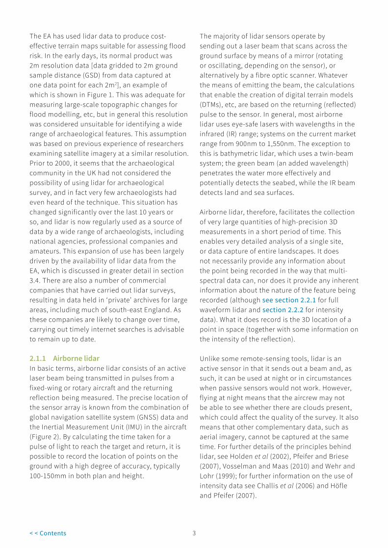
The EA has used lidar data to produce cost-effective terrain maps suitable for assessing flood risk. In the early days, its normal product was 2m resolution data [data gridded to 2m ground sample distance (GSD) from data captured at one data point for each 2m2], an example of which is shown in Figure 1. This was adequate for measuring large-scale topographic changes for flood modelling, etc, but in general this resolution was considered unsuitable for identifying a wide range of archaeological features. This assumption was based on previous experience of researchers examining satellite imagery at a similar resolution. Prior to 2000, it seems that the archaeological community in the UK had not considered the possibility of using lidar for archaeological survey, and in fact very few archaeologists had even heard of the technique. This situation has changed significantly over the last 10 years or so, and lidar is now regularly used as a source of data by a wide range of archaeologists, including national agencies, professional companies and amateurs. This expansion of use has been largely driven by the availability of lidar data from the EA, which is discussed in greater detail in section 3.4. There are also a number of commercial companies that have carried out lidar surveys, resulting in data held in ‘private’ archives for large areas, including much of south-east England. As these companies are likely to change over time, carrying out timely internet searches is advisable to remain up to date.
2.1.1 Airborne lidarIn basic terms, airborne lidar consists of an active laser beam being transmitted in pulses from a fixed-wing or rotary aircraft and the returning reflection being measured. The precise location of the sensor array is known from the combination of global navigation satellite system (GNSS) data and the Inertial Measurement Unit (IMU) in the aircraft (Figure 2). By calculating the time taken for a pulse of light to reach the target and return, it is possible to record the location of points on the ground with a high degree of accuracy, typically 100-150mm in both plan and height.
The majority of lidar sensors operate by sending out a laser beam that scans across the ground surface by means of a mirror (rotating or oscillating, depending on the sensor), or alternatively by a fibre optic scanner. Whatever the means of emitting the beam, the calculations that enable the creation of digital terrain models (DTMs), etc, are based on the returning (reflected) pulse to the sensor. In general, most airborne lidar uses eye-safe lasers with wavelengths in the infrared (IR) range; systems on the current market range from 900nm to 1,550nm. The exception to this is bathymetric lidar, which uses a twin-beam system; the green beam (an added wavelength) penetrates the water more effectively and potentially detects the seabed, while the IR beam detects land and sea surfaces.
Airborne lidar, therefore, facilitates the collection of very large quantities of high-precision 3D measurements in a short period of time. This enables very detailed analysis of a single site, or data capture of entire landscapes. It does not necessarily provide any information about the point being recorded in the way that multi-spectral data can, nor does it provide any inherent information about the nature of the feature being recorded (although see section 2.2.1 for full waveform lidar and section 2.2.2 for intensity data). What it does record is the 3D location of a point in space (together with some information on the intensity of the reflection).
Unlike some remote-sensing tools, lidar is an active sensor in that it sends out a beam and, as such, it can be used at night or in circumstances when passive sensors would not work. However, flying at night means that the aircrew may not be able to see whether there are clouds present, which could affect the quality of the survey. It also means that other complementary data, such as aerial imagery, cannot be captured at the same time. For further details of the principles behind lidar, see Holden et al (2002), Pfeifer and Briese (2007), Vosselman and Maas (2010) and Wehr and Lohr (1999); for further information on the use of intensity data see Challis et al (2006) and Höfle and Pfeifer (2007).

3 4< < Contents
Figure 2 Principles of lidar (after Holden et al 2002).
Summary � For archaeologists the key value of lidar is
the provision of accurate 3D measurements of a surface.
� Although lidar can be used from stationary or ground-based platforms, these guidelines focus on aircraft-mounted lidar sensors.
2.2 What does lidar provide?
Lidar is seen by some as a tool that will record all aspects of the historic environment, making other techniques redundant, especially when it is described as being able to ‘see through trees’. This is a misleading statement, however, and can lead to disappointment if the properties of lidar are not properly understood. The key element of lidar is light, and as such it cannot
see through trees or anything else. However, in certain circumstances significant gaps in the canopy make it possible to record the ground surface under woodland, something that is discussed in further detail in sections 2.3.2, 3.2.4 and throughout Section 5. What lidar can do is provide accurate locational and height data, enabling the creation of a 3D model of the land surface that can be examined for evidence of historic features that exhibit some form of surface topographic expression, although this does depend on the resolution of the data and on other factors, as described further in sections 2.4 and 3.4. The intensity of the reflection of the laser pulse can also, in some circumstances, provide useful information (see section 2.2.2 and Figures 7-10).
Like any other tool used for archaeological recording, lidar has strengths and weaknesses,

5< < Contents
and it depends to a large extent on the ability of the user to interpret the data effectively. Lidar will not make other techniques redundant, but will rather provide an additional source of data. Airborne lidar is particularly suited to large-area survey, for example a Historic England Level 2 survey (Historic England 2017b). For smaller areas lidar survey is still possible, but it becomes proportionally more expensive. Details of the different levels of survey defined by Historic England are given in the guidance document on understanding the archaeology of landscapes (Historic England 2017b) and should be considered before the initiation of any survey.
Figure 3Typical lidar tile showing heights differentiated by colour shading.
An alternative to lidar, particularly for small areas without much woodland or other vegetation cover, is structure from motion (SfM; Historic England 2017a), a photogrammetric technique based on imagery that enables the production of highly accurate digital surface models (DSMs). The use of SfM has expanded over recent years, particularly through the use of small unmanned aircraft (SUA) (also referred to as unmanned aerial vehicles, UAVs and drones). SfM systems can map small- to medium-sized areas with a degree of accuracy better than airborne lidar. The potential area that can be covered is restricted by a number of factors (The Survey Association 2013), such

5 6< < Contents
as Civil Aviation Authority (CAA) regulations (CAA 2017), battery life and the need to change location. A reasonable maximum area for the majority of SUA-acquired flights will generally be 2km × 2km, with surveys commonly in the 100m × 100m range (P Bryan, Historic England, pers comm).
For areas with vegetation there are now compact lidar sensors that can be mounted on SUA, although these are still in the early stages of use for any application and at the time of writing have not yet been tested by archaeologists. Additionally, operating SUA-
mounted sensors either through or over wooded areas creates problems for physically controlling the equipment and maintaining a line-of-sight between the operator and the aircraft, a legal requirement for many SUA flights.
Figure 4First and last returns: the image shows the scatter of points returned by the laser pulse; the blue points represent the last returns, which have penetrated to the ground, while the red and orange represent those that struck the canopy.
2.2.1 Height dataThere is a long tradition of archaeologists interpreting historic sites from ‘humps and bumps’, ie surface irregularities, visible on the ground or from the air. However, the height data recorded by lidar (Figure 3) is not a straightforward record of the ground surface. When the laser is fired from a sensor on a plane,

7< < Contents
the laser beam travels towards the ground and, if it strikes anything in passing, part of that beam is reflected back to the sensor and forms the first return; the rest of the beam continues towards the ground and may strike other features that produce further returns, until it finally strikes the ground or a surface that allows no further progression. The final reflection that reaches the sensor is known as the last return. In practice, built-up areas and open land act as solid surfaces and the first and last returns are often identical. Woodland, however, functions as a porous surface where the first return generally represents the top of the tree canopy and the last return may be a reflection from the ground surface but equally may be from the main trunks of the trees or areas of dense canopy or undergrowth (Figure 4)
For many early generation sensors, only a small number of return pulses were collected from each beam: often just the first and last returns, with occasionally an additional one or two in between. The first and last returns were considered the most important, the first being equivalent to the DSM and the last being used to help calculate a DTM. The DSM is a digital elevation model of the land surface; it records the highest points, including buildings and the woodland canopy.
Figure 5Full-waveform lidar (after Doneus): the image shows how the full waveform of the lidar pulse is recorded over various ground surfaces.
The DTM is a digital elevation model of the bare earth, ie the ground beneath any vegetation with other structures such as buildings removed.
One major change with regard to lidar sensors has been the development of the full-waveform (FWF) system where, instead of just recording between two and four returns, the entire analogue waveform is digitised for each emitted laser beam (Figure 5). During post-processing, it is possible, by combining the added detail from the whole pulse of the beam, such as the echo width and amplitude, to produce much more accurate models of the ground surface by more accurately eliminating ground cover such as low-level undergrowth, which can give a false reading that appears to be the ground surface (Doneus and Briese 2006; Doneus et al 2008). Being able to analyse the entire waveform also means that it is possible to obtain data from weaker returns and achieve a more accurate observation with better resolution of the return data. However, processing FWF data is complicated, so they are not used as much as standard discrete return data.
FWF systems have been available for a number of years (eg IGI LiteMapper; TopEye Mk II; and various sensors from RIEGL LMS, and Leica) and

7 8< < Contents
can provide good results. However, there is still quite limited software on the market that provides the end-user with full control over the analysis of FWF data (eg extracting individual returns from the waveform). The standard operating software provided with the proprietary systems tends to be expensive and you need to be experienced to use it efficiently. It is useful to have contacts with institutions that are researching FWF, although at present there are very few academic organisations in the UK that can handle (or are interested in handling) FWF for heritage applications. Hopefully there will be further advances in FWF analysis in the future.
Figure 6Typical lidar tile showing the intensity of the returned signal.
Using FWF digitisation produces significantly greater amounts of data at the time of survey, but after processing the size of the key dataset, the DTM, is solely dependent on the resolution required. Because of the additional time and cost required to process the data, use of FWF systems may only be appropriate for vegetated areas where the additional data can inform and enhance the vegetation-removal processing.
However it is generated, the most useful product from lidar for archaeologists is the 3D model of the ground, the DTM, because of the information it can provide about woodland; in non-wooded areas, a DSM is preferable because of the absence of smoothing effects (see section 4.2.2). The DTM

9< < Contents
Figure 7 (top left)Reflections from the first return are dominated by those from the woodland canopy.
Figure 8 (top right)Filtering the reflections to show only those from the last returns allow features such as sub-canopy water channels to become more evident.
Figure 9 (bottom) Lidar tile over Savernake Forest, Wiltshire, showing the Roman road appearing as a feature because of the difference in the intensity of the returned signal

9 10< < Contents
requires careful manipulation using specialist software, to facilitate analysis and interpretation of the archaeological features, discussed further throughout section 5.
2.2.2 Intensity dataWhile the height data are generally seen as the core product from the lidar survey, they are not the only information recorded. As well as the relative x, y and z position of the point on the ‘ground’, the sensor also records the intensity of the reflected signal. Intensity values are difficult to measure because, as well as the nature of the surface from which they are reflected, they can be affected by a combination of factors. The result is largely determined by the wavelength of the laser beam and the nature of the surface from which the pulse is reflected; different surfaces provide different absorption rates and consequently reflect back differing signal strengths, which can then be analysed to characterise the surfaces. However, the intensity can also be affected by factors such as flying height, laser power, atmosphere, direction of laser beam and the number of returns, which results in inconsistent values. There has been some attempt at post-processing the data to calibrate the values based on ground measurements, but the results have been inconclusive (Challis et al 2008a). Where the sensor has been calibrated in advance, better results have been recorded (Boyd and Hill 2007; Höfle and Pfeifer 2007).
Intensity data can be used to a certain extent as a proxy to analyse the reflectivity of the surface being hit by the laser beam, and thus aid in interpretation. When seen as a simple image file, the intensity information translates into a series of tonal differences and provides an image of the return surface similar to that of a true panchromatic orthophoto at the same resolution (Figure 6). However, because the lidar pulse is generally in the near infrared (NIR), rather than in the visible, spectrum, the reflectance might not be what you expect if you are not used to working with wavelengths outside the visible range (eg if you are used to dealing with standard aerial photographs). Whereas a flat, solid surface such as stone or concrete will reflect almost all of the
light in the visible spectrum, this is not the case with IR light: instead, asphalt for roads has a low return value, while grass or other green plants have a high return.
It was initially thought that there might be archaeological potential in using intensity values as a method of assessing the moisture content of exposed soils. A project funded by the Aggregates Levy Sustainability Fund (ALSF) investigated whether this could be used to predict the likelihood of preservation of waterlogged archaeological remains, but results have proved inconclusive (Challis et al 2008a). While the results suggested that, from a visual standpoint, the lidar intensity data were useful in qualitative analyses of certain areas, the report stated that ‘the application of lidar intensity data to predictively model sediment units of high preservation potential can be deemed at present to be untenable’. However, while the usefulness of the intensity data to identify damp ground seems uncertain, under other circumstances useful information can be retrieved. Changes in reflectance/absorption beneath a woodland canopy could be caused, for example, by areas of standing water, which are likely to absorb most of the energy from a pulse and reflect very little (Figures 7 and 8).
Another area of potential, although one that has had limited publications to date with lidar data, relates to the influence of chlorophyll. Chlorophyll in plants reflects NIR radiation, so changes in the chlorophyll content of a single plant species, perhaps as a result of stress such as drought, can be represented in intensity data in the same way that it can be seen in the visible spectrum as cropmarks. Because chlorophyll reflects c 50% of NIR radiation, as opposed to 15% of the visible spectrum, plant stress (eg grass growing over buried walls) is much easier to discern with NIR (Verhoeven and Loenders 2006). This has long been recognised by archaeologists, and was first systematically investigated by Hampton in the summer of 1970; he reported that, compared with standard film, NIR film ‘showed distinct advantages at the early stages of cereal growth’ (Hampton 1974). A limiting factor is that the

11< < Contents
Figure 10 (top)Aerial photograph of playing fields on Cannock Chase, Staffordshire, captured at the same time as the lidar survey shown in Figure 11.
Figure 11 (bottom)The same site as in Figure 10 (Cannock Chase, Staffordshire), as it appears in the lidar data, showing the outline of the playing fields as a result of the difference in the intensity of the returned signal.

11 12< < Contents
standard ALS laser wavelengths tend to be in the 1000–1500nm range. This is good for detecting changes in water absorption, but is some distance from the ’red edge‘ where differences in chlorophyll content would be more readily recorded/noticeable. However, there are examples where features do appear within intensity data.
While lidar intensity data have not been tested extensively by Historic England, one striking example of its potential has been shown in Savernake Forest, Wiltshire, on the course of the Roman road leading to the Roman town of Cunetio. The lidar height data did not reveal the course of the road, but the side ditches could be seen clearly in the intensity data (Figure 9). Unfortunately, no photography was captured at the time of the lidar flight so it is not known whether these ditches could also be seen as cropmarks in the visible spectrum at that time, but they have been visible on other occasions.
More recent examples come from Cannock Chase, Staffordshire (see case study 1), where lidar data and aerial imagery were captured at the same time as part of the Chase Through Time project. In one example, a sinuous ditch was visible in the aerial photography and also in the lidar intensity data. A second example showed features more clearly, although they were not of any great antiquity. The outlines of former playing fields marked out for football and hockey are clearly visible in Figure 10 as green-on-green cropmarks on the aerial imagery. The outlines of at least parts of the football pitch are also visible in the lidar intensity data (Figure 11). As with all imagery, processing within image manipulation software can help to highlight more subtle features.
Summary � The primary product of lidar survey is 3D
data; this is only effective for recording features that exhibit some form of surface topographic expression.
� The key element of lidar is light and as such it cannot ‘see through trees’ or directly identify sub-surface features.
� In appropriate circumstances, in wooded areas, the last return lidar data can provide measurements of the forest floor. This is a major advantage, as measuring features within woodland had previously been extremely complex and time consuming.
� FWF lidar enables much more accurate recording of ground surfaces within wooded and otherwise vegetated environments, but its use is limited by the complexity of processing required.
� Intensity data can be used to analyse the reflectivity of the surface being hit by the laser beam and thus aid in interpretation in a similar way as cropmarks on traditional aerial photographs.
2.3 Data types
During the process of a lidar survey there are a number of stages at which data are generated and can be provided to a client. However, in order to be able to reprocess and manipulate the data to gain the maximum benefit from them, it is important to ensure that the most appropriate type of data is chosen. It is also important to be aware of the processing stages the data have been through, as each of these can result in misleading data artefacts.
The primary data are collected by the sensor simply as a series of points in space based on the calculated time taken for the beam to return to the sensor. It is only after these data have been registered (placed in a common coordinate system) and quality checked that they are readily usable. This procedure is carried out by the data provider. After the data have been registered, it is then necessary to align the grids of individual survey swathes to ensure that there are no discrepancies between scans that could lead to interference patterns. Again this procedure is best carried out by the data provider. Once these processes have been completed the first commonly available product can be generated: a fully georegistered point

13< < Contents
cloud. This is still just a collection of points floating in space, with no relationship between any given point and its neighbours. As such it is a relatively non-user-friendly product and is not generally of interest to archaeologists. There is a range of proprietary formats for providing laser-scanned data, but there is a growing consensus that the standard format for recording 3D point data should be the American Society for Photogrammetry and Remote Sensing (ASPRS) LAS (version 1.2 and higher) (ASPRS 2013; Graham 2007). An alternative compressed format, LAZ, significantly reduces file size. A LAZ file is a LASzip compressed data file created via a free open source product of rapidlasso GmbH. LASzip quickly turns bulky LAS files into compact LAZ files without information loss.
The next stage is to transform the point cloud into a surface, either a DSM (as discussed in section 2.2.1), or a DTM, using classification algorithms to identify and remove above-ground points. Various different software packages can be used to carry out this transformation, including both proprietary and open-source solutions, but in most cases this step is not undertaken by the archaeologist, who is more interested in the finished product. The processed surfaces can then be manipulated by the archaeologist within specialist software to emphasise the features of interest.
Whenever possible, you should try to gain some understanding of the processing that has been carried out by the data provider so that you are aware of any potential issues of data degradation or artefact creation. This is particularly important where filtered bare-earth DTMs are provided that may have used classification algorithms to extract and remove buildings and any other features (see section 4.2.2).
The data can be provided at different stages of the process in a variety of forms and as a range of products (eg point clouds, pulse data, images, DTMs, DEMs), the suitability of which depends on their original intended use. Unfortunately, although the use of lidar within the archaeological world is becoming more common, most users
still have limited experience of the technical side of the process. As a result, the discussion of formats, etc, can appear quite jargon heavy and off-putting. Many of the terms will be familiar if you are used to working with a geographical information system (GIS) or other remote-sensing techniques, but may be confusing if you commission surveys or want to utilise existing data. While it is not essential to understand all the technicalities of how lidar operates, it is useful to know the key terminologies and the differences between the various products.
2.3.1 Raw and gridded data; TINs and rasterThe two most obvious differences in data products are between what are often referred to as ‘raw’ and ‘gridded’ data. In raw data the individual points are scattered across the survey area exactly as they have been recorded, while in gridded data the survey points have been processed to form a regularly spaced array.
In basic terms, raw data are simply a series of tables that record the x, y, z and intensity data for large numbers of points on the ground (note that ‘the ground’ refers to the surface struck by the laser pulse and does not necessarily equate to a point at ground level). If point data are viewed as a text file, they are simply rows of numbers with columns for x, y, z and intensity data values. Additional sets of columns may be provided to separate first and last (or intermediate) returns. Each row equates to data from a single laser pulse.
The x and y points are used to map the actual centre point of the laser footprint to a national grid reference (NGR), for example, in the UK, the Ordnance Survey (OS). The z coordinates provide the elevations of the points of reflection. In some cases the z coordinates are recorded in centimetres or millimetres rather than in metres, and this can cause problems when visualising in a GIS. When imported into a GIS package, the x, y and z points produce a point cloud, which is exactly that: a cloud of points.
A useful way to visualise a point cloud (P Crow, Forest Research, pers comm) is to liken it to snow,

13 14< < Contents
Figure 12 (top)A point cloud showing how the general structure of features can be revealed.
Figure 13 (bottom)A point cloud showing how features can be viewed using enlarged points.

15< < Contents
with flakes (lidar points) ‘settling’ on each surface that they contact; some flakes will be scattered over trees and bushes and fences, and some will also reach the ground. If you mentally remove everything on which the ‘snow’ has settled, you are left with a cloud of flakes floating in 3D space, and a lidar point cloud resembles this (Figures 12 and 13). A point cloud is defined in 3D Laser Scanning for Heritage as ‘a collection of points converted from range and angular measurements into a common Cartesian (x, y, z) coordinate system that defines the surfaces of the subject in great detail’ (Historic England 2018). The key thing to remember about a point cloud is that these are individual points in space that have no physical relationship between each other but, because of
their density, they can still help define features. The increase in the number of returns coupled with the higher point densities available with the latest generation of sensors means that point clouds can be very large and difficult for some computers to handle. Where there are features that could be viewed using the point cloud, it can be advantageous to crop the cloud to reduce the file size. As well as within a standard GIS package, there are online sites for viewing point clouds. Some online sites are listed in section 9.2 but, because of the constantly evolving nature of lidar a search is always recommended to find the most up-to-date resources.
Figure 14A wireframe TIN surface model of the same area as Figure 15 showing the nodes connected by edges.
15 16< < Contents
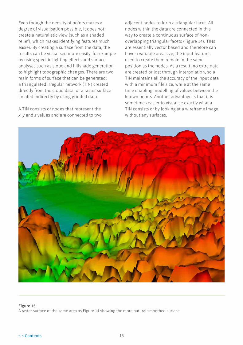
Even though the density of points makes a degree of visualisation possible, it does not create a naturalistic view (such as a shaded relief ), which makes identifying features much easier. By creating a surface from the data, the results can be visualised more easily, for example by using specific lighting effects and surface analyses such as slope and hillshade generation to highlight topographic changes. There are two main forms of surface that can be generated: a triangulated irregular network (TIN) created directly from the cloud data, or a raster surface created indirectly by using gridded data.
A TIN consists of nodes that represent the x, y and z values and are connected to two
adjacent nodes to form a triangular facet. All nodes within the data are connected in this way to create a continuous surface of non-overlapping triangular facets (Figure 14). TINs are essentially vector based and therefore can have a variable area size; the input features used to create them remain in the same position as the nodes. As a result, no extra data are created or lost through interpolation, so a TIN maintains all the accuracy of the input data with a minimum file size, while at the same time enabling modelling of values between the known points. Another advantage is that it is sometimes easier to visualise exactly what a TIN consists of by looking at a wireframe image without any surfaces.
Figure 15A raster surface of the same area as Figure 14 showing the more natural smoothed surface.

17< < Contents
A raster surface is different from a TIN because it is stored in grid format, ie a grid of defined cell size is effectively draped over the point data and each cell is allocated the z value that falls within it. Because it consists of a regular array, the points are ‘derived’ from the original data, rather than comprising the actual points that were captured in the survey. Any empty cells have values allocated that are derived through the interpolation of adjacent points. Cells containing multiple points will usually be given an average value, which means that they do not make full use of all the available data. The smaller the cells, the greater the precision of the grid or, in other words, the higher the resolution of the image. Unfortunately this comes at the cost of larger file sizes. Because values are interpolated into the grid, it is impossible to locate individual features more precisely than the size of the grid cells.
Care should be taken with a raster surface, as creating cells of a larger size than the resolution of the data capture will result in loss of information. Equally, while using a cell size smaller than the resolution of the original data capture can produce ‘sharper images’, the interpolation required will create artificial data in addition to that captured.
For example, if a survey is captured at one laser hit per square metre (1 point per metre; 1ppm), creating a grid with a 0.5m cell size would result in 75% of the final data being calculated rather than measured, and will therefore be less reliable. If two hits per square metre (2ppm) were initially captured, then a grid of 0.5m cells would double the number of data points in the raster surface. Interpolation should not exceed this doubling of data. This may be less of an issue for new data capture, as faster sensors produce higher point densities, but is relevant for archived datasets. Interpolation over areas with no data, especially in vegetated areas, will further reduce the resolution of the final model (see section 5).
While it maintains the accuracy of the original data better, a TIN is not generally as easy to manipulate as a raster surface of comparable size. In most cases the surfaces produced by suppliers will tend to be raster, as they are simpler to create and fulfil the main requirements of lidar surfaces (Figure 15). Furthermore, in many standard GIS packages a TIN has to be converted into a raster surface before any further visualisations can be produced or additional analysis carried out. TINs are therefore not considered further here.
Box 1 As already noted, and discussed further in section 2.3.2, there are some key differences between data provided as a point cloud and data provided as a surface. Data can be provided either as ‘filtered’ (ie above-ground points removed) or ‘unfiltered’ (ie all points). Such data can then be provided in either point cloud or surface format, to make them easier to visualise and understand as a surface. In each case, the data can be provided as a gridded raster image or as a TIN. There are advantages and disadvantages to both point cloud and surface format data.
Point cloud Advantages
� All the subtleties are present in point cloud form; no data have been lost during the gridding process.
� If provided as x, y and z data, they can be read by most standard GIS software but are best viewed in specific point cloud software.
� With additional 3D components to GIS or stand-alone software, it is possible to manipulate the data extensively.
� There are no additional processing costs.
Disadvantages
� Visualisation and interpretation are more difficult: you need to be able to mentally filter out distractions and imagine how to join the dots, particularly when trying to spot landscape-scale patterns.
� Because of the large files, using point cloud data usually requires a computer with good RAM and graphics display capability.

17 18< < Contents
SurfaceAdvantages
� The data are easily readable in standard GIS software.
� Surfaces are much easier to visualise, and additional visualisations and analyses can be made.
� They facilitate cross-section investigation of elevated landscapes and features.
Disadvantages
� With raster surfaces, there is the risk of some loss of original data resolution, leading to smoothing away of features or creating a greatly increased dataset from using smaller cell sizes.
� Misleading data-processing artefacts can be created by the process of interpolation; likewise areas of no data collection can be ‘masked’ by the averaging process.
� Depending on the format of processed data, there will be limited options for manipulation, eg if a surface is provided as a filled, smoothed product, you cannot reprocess to remove the fill.
� There are additional processing costs.
Although there are additional processing costs related to the creation of surfaces, it is not possible to use the data purely as a point cloud for historic environment purposes.
Figure 16The process of creating a digital terrain model (DTM), after Ziga Kokalj.

19< < Contents
Note the trees at the top of the image and the features in the middle.
Note that as well as removing trees there has been a softening of archaeological detail, particularly for the lead-mining adit in the foreground and the quarry and small dam in the centre of the image.

19 20< < Contents
Figures 17 (opposite, top)A comparison of lidar digital surface models (DSM) and digital terrain models (DTM). DSM of the same site near Alston, Cumbria, as in Figure 18.
Figure 18 (opposite, bottom)A comparison of lidar digital surface models (DSM) and digital terrain models (DTM). DTM of the same site near Alston, Cumbria, as in Figure 17.
Figure 19 (top)Digital surface model (DSM) of an area of woodland in Savernake Forest, Wiltshire, showing the tree canopy lidar.
Figure 20 (bottom)Digital terrain model (DTM) of the same area as Figure 19 clearly showing the course of the Roman road.
21< < Contents
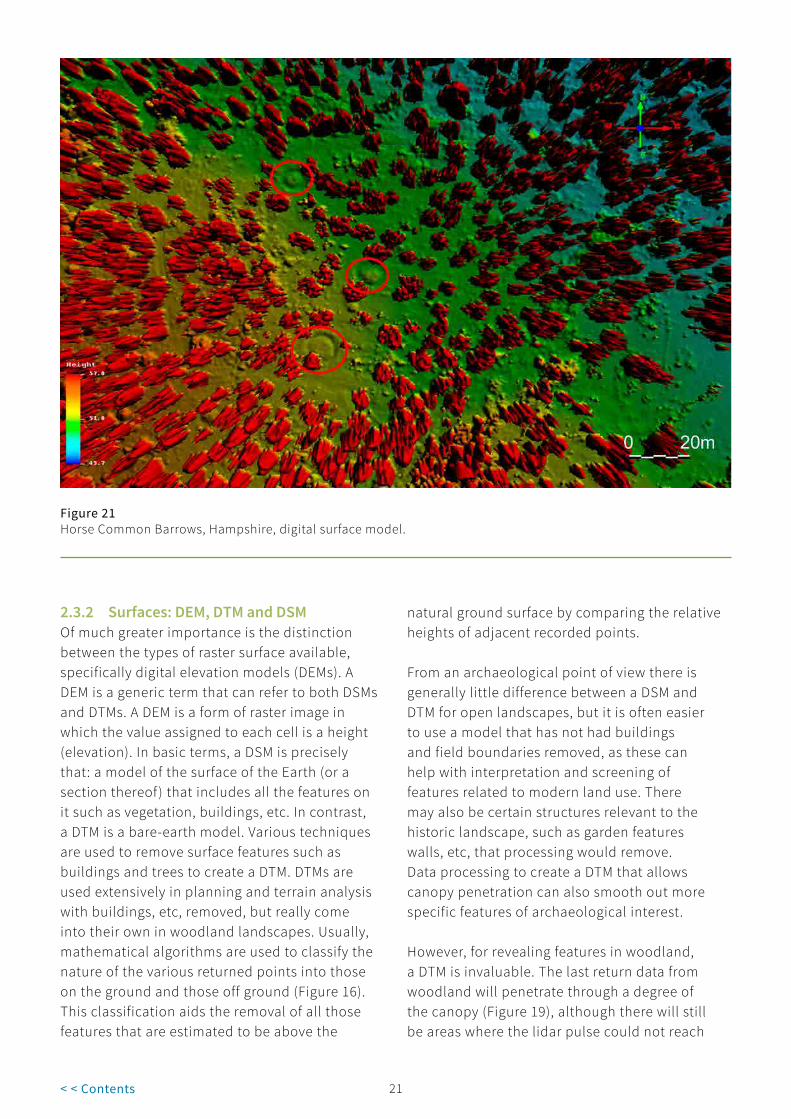
Figure 21Horse Common Barrows, Hampshire, digital surface model.
2.3.2 Surfaces: DEM, DTM and DSMOf much greater importance is the distinction between the types of raster surface available, specifically digital elevation models (DEMs). A DEM is a generic term that can refer to both DSMs and DTMs. A DEM is a form of raster image in which the value assigned to each cell is a height (elevation). In basic terms, a DSM is precisely that: a model of the surface of the Earth (or a section thereof) that includes all the features on it such as vegetation, buildings, etc. In contrast, a DTM is a bare-earth model. Various techniques are used to remove surface features such as buildings and trees to create a DTM. DTMs are used extensively in planning and terrain analysis with buildings, etc, removed, but really come into their own in woodland landscapes. Usually, mathematical algorithms are used to classify the nature of the various returned points into those on the ground and those off ground (Figure 16). This classification aids the removal of all those features that are estimated to be above the
natural ground surface by comparing the relative heights of adjacent recorded points.
From an archaeological point of view there is generally little difference between a DSM and DTM for open landscapes, but it is often easier to use a model that has not had buildings and field boundaries removed, as these can help with interpretation and screening of features related to modern land use. There may also be certain structures relevant to the historic landscape, such as garden features walls, etc, that processing would remove. Data processing to create a DTM that allows canopy penetration can also smooth out more specific features of archaeological interest.
However, for revealing features in woodland, a DTM is invaluable. The last return data from woodland will penetrate through a degree of the canopy (Figure 19), although there will still be areas where the lidar pulse could not reach

21 22< < Contents
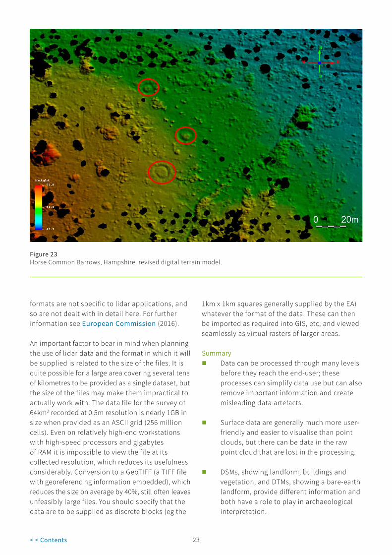
the ground surface, because of returns caused by tree trunks, etc. By processing these data with algorithms to create the bare-earth DTM, an unrivalled view of the woodland floor can be created (Figure 20). There are different degrees of processing available, using a range of different algorithms, that produce different results. If the data are processed too aggressively, it is possible to remove subtle features (Figures 17 and 18). In some cases the processing removes features that could have helped with the interpretation of the features that are left (see Figures 43 and 44, section 4.2.2); in others entire features can be lost (Figure 22). If possible, it is always worth comparing the final product with an area of known archaeology, or known features of recent date, to be sure that excessive smoothing has not taken place (Figure 21). This is best carried out by a ground visit to the area of interest. If you have access to the original point cloud data, you can also get them reprocessed (Figure 23) if you are unhappy with the original results.
Figure 22 Horse Common Barrows, Hampshire, original digital terrain model.
2.3.3 File formatsElevation models can be provided in a number of formats depending on the requirements of the end-user and on the software that is being used to analyse the data, so it is important to be clear about how the data will be used from the outset. The simplest way to view the data is as an image, either as hardcopy or in a standard image format as used for digital photographs (eg TIFF and JPEG). These are usable to a point, but are somewhat limited and do not take advantage of the full potential of elevation data. However, there are situations where the use of basic imagery can provide a useful tool for further research and analysis.
There are some issues with image files that relate to the different file formats available, such as product-specific (eg IMG) versus generic (eg JPEG). The nature of image files is such that they contain different levels of data, often in relation to their file size. Concerns with viewing different image
23< < Contents
formats are not specific to lidar applications, and so are not dealt with in detail here. For further information see European Commission (2016).
An important factor to bear in mind when planning the use of lidar data and the format in which it will be supplied is related to the size of the files. It is quite possible for a large area covering several tens of kilometres to be provided as a single dataset, but the size of the files may make them impractical to actually work with. The data file for the survey of 64km2 recorded at 0.5m resolution is nearly 1GB in size when provided as an ASCII grid (256 million cells). Even on relatively high-end workstations with high-speed processors and gigabytes of RAM it is impossible to view the file at its collected resolution, which reduces its usefulness considerably. Conversion to a GeoTIFF (a TIFF file with georeferencing information embedded), which reduces the size on average by 40%, still often leaves unfeasibly large files. You should specify that the data are to be supplied as discrete blocks (eg the
1km x 1km squares generally supplied by the EA) whatever the format of the data. These can then be imported as required into GIS, etc, and viewed seamlessly as virtual rasters of larger areas.
Figure 23Horse Common Barrows, Hampshire, revised digital terrain model.
Summary � Data can be processed through many levels
before they reach the end-user; these processes can simplify data use but can also remove important information and create misleading data artefacts.
� Surface data are generally much more user-friendly and easier to visualise than point clouds, but there can be data in the raw point cloud that are lost in the processing.
� DSMs, showing landform, buildings and vegetation, and DTMs, showing a bare-earth landform, provide different information and both have a role to play in archaeological interpretation.

23 24< < Contents
� In areas of largely open landscape, using a DSM or unprocessed last-return data is preferable to using a DTM.
2.4 Accuracy and resolution
For archaeologists, the key data recorded by lidar are height data or, more accurately, 3D coordinates on the ground. It is the height values that are emphasised because they make the detection of features of archaeological interest possible, but the x and y coordinates are just as important to locate the features accurately on the ground. However, it should be noted that what is actually recorded by the sensor is only relative data; it is the GNSS and IMU recording of the position of the sensor that makes it possible to obtain absolute coordinates.
There are, therefore, two levels of accuracy that can be provided for a given sensor and/or a given survey: absolute and relative. The relative accuracy of the data is typically in the range of 100-150mm, although it can be 70-80mm, while the absolute accuracy depends on datum registration. In most cases within the UK, registration will use the OS national grid. However, in general laser-scanned data are registered initially against WGS84 (World Geodetic System 1984; see Glossary) and subsequent transformation to the UK OS can create potential distortions, depending on the transformation used. These issues should normally be addressed by the supplier and need not be a cause for concern, but it is worth remembering that there are potential problems with absolute accuracy if combining other highly accurate data.
Figure 24The effect of resolution on feature visibility: part of the First World War camp at Brocton on Cannock Chase, Staffordshire. Resolution clockwise from top left 0.25m, 0.5m, 1m and 2m (ground sample distance; GSD).

25< < Contents
Figure 25Point density: the actual distribution of points over an area.
In many cases, for the archaeologist it is the relative difference that is more important than the absolute difference, as the former reveals the presence of features. It is the fact that there is an area of ground that is slightly above or below the surrounding level that reveals the presence of a bank or ditch. At the first level of information and interpretation, it is less important whether the feature is at 120.25m ordnance datum (OD) or 122.25m OD than whether it accurately depicts the presence of a previously unrecorded enclosure, but the difference in absolute accuracy may lead to difficulties in interpretation and registration of adjacent lidar datasets (see Figure 30, showing a wavy swath edge) and when additional data are recorded using ground-survey techniques with a higher level of accuracy (eg GNSS).
It is not only the accuracy of the lidar data that needs to be considered, but, as with any remote-sensing technique applied to the recording and interpretation of archaeological features, also its resolution. However, unlike imagery, where
any feature that is smaller than the resolution of the data will not appear, with lidar the issue is more complex because resolution is a relevant factor at different stages of the process and is consequently affected by different specifications.
The resolution of the gridded data that are used for visualisation is important because it limits the size of the features that can be seen and recorded, much in the same way as for other image-based data, such as satellite or standard aerial photography. Figure 24 shows how this can affect the visualisation of different archaeological features. The image shows part of the First World War camp at Brocton on Cannock Chase, Staffordshire, at decreasing resolution clockwise from top left. A general rule of thumb for remote-sensing is that only features of a size 3× the resolution of the model in at least one dimension will be detectable.
More important for the accuracy of visualisations, is the original resolution of
25 26< < Contents
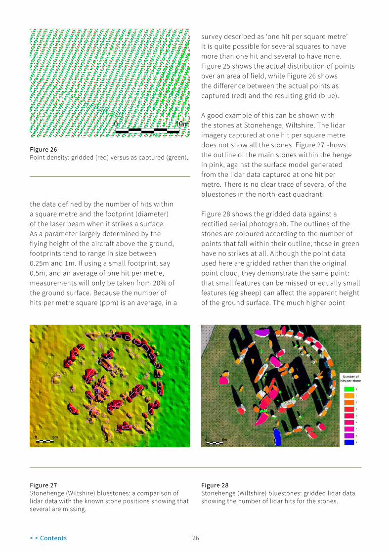
the data defined by the number of hits within a square metre and the footprint (diameter) of the laser beam when it strikes a surface. As a parameter largely determined by the flying height of the aircraft above the ground, footprints tend to range in size between 0.25m and 1m. If using a small footprint, say 0.5m, and an average of one hit per metre, measurements will only be taken from 20% of the ground surface. Because the number of hits per metre square (ppm) is an average, in a
survey described as ‘one hit per square metre’ it is quite possible for several squares to have more than one hit and several to have none. Figure 25 shows the actual distribution of points over an area of field, while Figure 26 shows the difference between the actual points as captured (red) and the resulting grid (blue).
Figure 26Point density: gridded (red) versus as captured (green).
A good example of this can be shown with the stones at Stonehenge, Wiltshire. The lidar imagery captured at one hit per square metre does not show all the stones. Figure 27 shows the outline of the main stones within the henge in pink, against the surface model generated from the lidar data captured at one hit per metre. There is no clear trace of several of the bluestones in the north-east quadrant.
Figure 27Stonehenge (Wiltshire) bluestones: a comparison of lidar data with the known stone positions showing that several are missing.
Figure 28Stonehenge (Wiltshire) bluestones: gridded lidar data showing the number of lidar hits for the stones.
Figure 28 shows the gridded data against a rectified aerial photograph. The outlines of the stones are coloured according to the number of points that fall within their outline; those in green have no strikes at all. Although the point data used here are gridded rather than the original point cloud, they demonstrate the same point: that small features can be missed or equally small features (eg sheep) can affect the apparent height of the ground surface. The much higher point

27< < Contents
densities now possible means that this is less likely to be an issue with recent and new surveys, but it is worth bearing in mind, especially when using archive data that may have been captured at a lower resolution.
A second example of this effect is illustrated with lidar data taken of an area of the Welsh coast to monitor for the erosion of a promontory fort (Figure 29). Comparison with a ground-based GNSS survey carried out by the Royal Commission on the Ancient and Historical Monuments of Wales (RCAHMW) showed substantial discrepancies in the position of the cliff edge, which was probably because some laser pulses were on the extreme edge of a given 2m square and missed the cliff entirely. For others, the centre point of the footprint
was over the edge of the cliff, but the height recorded was for the top, resulting in the cliff appearing to extend further than it actually does.
Figure 29Linney Head promontory fort, Pembrokeshire, showing the discrepancy between lidar-modelled data and a ground-based GNSS survey (ground survey results in red) (NPRN 94226).
Careful planning at the data capture stage can minimise later difficulties with resolution. Higher densities of points are required in woodland to maximise the potential of some points reaching the forest floor. Even in the early days of lidar surveys, those in wooded landscapes were carried out at at least two points per metre (2ppm) with gridding to four, ie a nominal 0.5m GSD ground resolution. However, woodland survey is complicated by the fact that a percentage of the laser pulses will fail to reach the forest floor, thereby reducing the final point density. In these situations it is important to specify an expected average density for the final filtered data and

27 28< < Contents
then allow the contractor to calculate the ppm required to achieve it. More recently, it is common for woodland surveys to be flown at 8ppm or even 16ppm to achieve the required 0.25m gridded data. Originally, the surveys also had a fairly large footprint to maximise the chance of getting a reflection from the forest floor, and transects had a 65% overlap to ensure good coverage. The increased point density has also meant that smaller footprints and overlaps of closer to 50% are common. The increased power of modern lasers has improved canopy penetration, thereby boosting the number of hits reaching the forest floor. It is important to consider the aims of your project and therefore the correct data resolution for your needs.
All the airborne lidar data discussed in sections 1, 2 and 3 relate to data collected from fixed-wing aircraft, which, because of restrictions on speed and altitude, have been limited to up to 8ppm with each pass. This is improving with the latest range of sensors, and a fixed-wing survey with a 40% overlap can now collect more than 8ppm. Surveys on the South Downs and in Norfolk have achieved point densities of between 16ppm and 40ppm. It is also possible to collect more points by carrying out multiple passes, but this has implications for flight time and consequently for costs. There are systems on the market that are designed to be mounted on helicopters (and SUAs) that can collect much higher densities of data. The FLI-MAP® systems were used by Department for Environment, Food and Rural Affairs (DEFRA) to measure changes in beach levels and recorded between 12ppm and 28ppm (McCue et al 2004), while the Discovery Programme in Ireland surveyed Dún Ailinne prehistoric hillfort in Co. Kildare at 15-30ppm, and the Hill of Tara at 60ppm, using FLI-MAP 400 (Corns et al 2008). This higher resolution shows a much greater degree of detail, but comes at the price of generally smaller areas being flown, although this is becoming less of an issue as sensors become faster.
Summary � For archaeological analyses, relative
accuracy is often more important than absolute accuracy.
� The relative accuracy of the data is typically in the 10mm range (100–150mm) but can be higher.
� The absolute accuracy of the recorded data is heavily dependent on the accuracy of the GNSS and IMU used.
� The resolution of the gridded data is important because it limits the size of the features that can be seen and recorded; 2m resolution data are generally inadequate for recording many archaeological features; 1m resolution is the basic minimum but where greater detail is required higher resolution data are preferable.
� Survey in woodland requires higher resolution data (typically 2ppm or more, gridded to 0.5m ground resolution or higher) to achieve sufficient canopy penetration.
� The original point density determines the final resolution, as insufficiently densely and regularly spaced points can risk missing features altogether.
� Low-altitude surveys can record points up to a density of 60ppm, but for large area surveys 1ppm or 2ppm (gridded to 1m resolution) are adequate to record most features of interest. However, improvements in sensors mean 0.5m data and higher are more readily available and this is obviously better for recognising and interpreting smaller features as well as picking out details.
� The correct resolution should be obtained/commissioned to meet the needs of a project.

29< < Contents
3 Deciding to Use Lidar
3.1 Project planning
A decision tree is given in Section 8.
3.1.1 MoRPHE and Historic EnglandThe potential for lidar data to contribute to a project should be identified as early as possible in the planning process. Following Management of Research Projects in the Historic Environment: The MoRPHE Project Managers’ Guide (Historic England 2015), its use should be assessed as part of the project design document. You will need to decide whether a lidar survey is appropriate for the site or landscape in question, and whether it will yield useful results. Historic England Science Advisors and members of research teams can provide advice: see section 9.1.1 and https://HistoricEngland.org.uk/research/methods/. Historic England staff have expertise in remote sensing and geospatial imaging, including the use of SUA and SfM, and can help you compare the relative costs and applicability of alternative terrestrial survey techniques for archaeological interpretation, especially if the survey area is quite small or if the level of detail required is higher than will be readily achievable using lidar data. If your survey area covers a largely wooded area, then technical advice can also be obtained from Forest Research (see section 9.1.2).
3.1.2 Survey considerations and optionsAs with any planned project data, before any work is undertaken you should be clear about the objectives, requirements and end-use of the lidar data. Lidar as a technique has been around for some time, but its large-scale use by archaeologists is a more recent development.
While it is very useful in certain situations and can produce spectacular results (Bewley et al 2005; Devereux et al 2005) it is less useful in other situations and always needs careful interpretation (Crutchley 2006).
A key point to remember is that lidar primarily records height information, therefore the features being surveyed must have a 3D surface aspect, ie they appear as ‘humps and bumps’. As noted in section 2.2.2, the intensity data from lidar returns are able to record certain aspects of the reflective nature of the surface, which may provide information on factors such as angle, roughness, dampness and colour absorbency, but only in exceptional cases will this information directly reveal archaeological features.
Lidar does not penetrate the ground. If the archaeological features of interest are not represented on the ground surface, then lidar will not be able to record anything except the general topography of the survey area. Having an accurate record of the general topography of an area and the surrounding landscape can be a useful resource in itself, but if this is all that is required then lidar may not be the most appropriate, or cost-effective, method with which to collect these data. Basic topographic height data at scales suitable for general topographic relief are available from alternative sources. Depending on the resolution required there are commercial datasets available, for example from the OS and NEXTMap®, and some freely available data, for example from the US Geological Service and NASA.

29 30< < Contents
If there are likely to be features that can usefully be recorded by lidar, the next stage is to be clear about the end-use of the data. Is the lidar data needed as a primary source, as an interrogatable dataset that can be analysed by different staff to provide an interpretation of archaeological features, or is it to be used as a background layer for other datasets available elsewhere? This decision will determine the form in which the data will be provided, which will in turn dictate the requirements for software and hardware. The precise nature of these options is discussed in more detail below.
If the aim is to use the surface model derived from the lidar data as a background layer, the hardware and software requirements will probably be quite low but processing the data to an appropriate format for GIS, etc (see section 3.3), will need to be budgeted for. If, however, the intention is to analyse the data inhouse and carry out a variety of investigations, then the appropriate hardware and software must be available to deal with large datasets. It is possible to view the processed data that are provided by most suppliers in standard GIS packages, such as ArcGIS, MapInfo or QGIS (see section 9.2), which provide the best means to interrogate and analyse the data.
However, it is not just a question of hardware and software, but also of technical expertise. A basic understanding of the processes used to generate the models is desirable, and recommended if you want to be confident using the data provided by the contractor. If you do not already have a reasonable grasp of the use of GIS, there may be a learning curve (see section 2.3).
Similarly, the interpretation of archaeological features from lidar models is best done by someone with some previous experience, in particular someone used to looking at aerial imagery. This is important if the intention is to compare different sources of data, which is recommended as discussed in section 3.3.
If there is a further requirement to map the archaeological data (or indeed any other type of feature) from the lidar data, then a different set of
problems needs to be addressed. Until recently there were no simple tools for mapping directly from processed lidar data, ie derived surface models that could be manipulated to control height exaggeration and lighting position (see section 4.2), and Historic England has developed its own workflow. Given the rapid development of software and hardware capabilities, it is best to consult with someone already actively working with such processed data.
Summary � Advice on whether lidar can be useful for
a given landscape can be obtained from Historic England staff.
� Technical advice on the use of lidar data can be obtained from Historic England.
� Historic England can advise on the likely cost benefits and applicability of alternative terrestrial survey techniques.
� If the survey area covers a largely wooded area, then technical advice can be obtained from Forest Research.
� There is a growing number of private companies and consultants who can provide advice on various aspects of lidar data acquisition and use, which can be found online.
� Basic topographic height data at scales suitable for general topographic relief are available from alternative sources, eg the OS and NASA.
� It is important to be clear whether the lidar data are required as a primary source or whether they will be used as a background layer to other datasets available elsewhere.
� To make best use of lidar for archaeological survey, the project team should include someone with experience in interpreting aerial data.

31< < Contents
3.2 Where can you use it?
One of the major factors affecting the usefulness of lidar is the current land-use of the area of interest, as this can have a major impact on the survival and consequent visibility of features.
3.2.1 GrasslandMany archaeological earthworks are found in areas of open grassland, and lidar can be a useful tool in such landscapes. Although archaeological aerial reconnaissance and field survey have often targeted such areas in the past to great effect, and continue to do so, the manipulability of lidar data can provide a valuable additional tool. This is particularly the case for improved pasture, one of the more difficult types of landscape for survey by other means. Ploughing can eradicate most traces of any former earthworks, but the presence of grass rather than an arable crop restricts the potential of cropmarks to periods of extreme drought. However, if there are any traces of earthworks surviving, even in a smoothed and eroded state, then lidar is an excellent tool for recording them. This is true for all forms of grassland, ranging from upland grass and stone landscapes, such as the Yorkshire Dales, to coastal saltmarsh.
3.2.2 MoorlandMoorland is another landscape type where ground survey is often difficult and dependent on season. Typical moorland vegetation, such as bracken and heather, can make the surveying of features on the ground difficult and limit the window of recording to certain times of the year. The timing of any lidar survey flight is likely to be of particular importance. Although it is possible that the use of last return data will enhance the visibility of features under heather and gorse during autumn and winter, it is likely that at other times they will prove too dense for the laser beam to penetrate.
It had been suggested that there might be issues with the use of lidar on open-stone landscapes or on features created from stones, for example cairns and rock waste mounds, because of the possibility of multiple reflections from the various
surfaces. However, work by Historic England in the North Pennines and the Lake District and Yorkshire Dales found this not to be an issue. Similar work has been carried out by the Forestry Commission Scotland (FCS) at a number of their sites, including the clearance village of Rosal near Syre in Strathnaver, Sutherland, and at Kraiknish on the west coast of Skye.
Commissioning bespoke high-resolution survey for archaeological landscape survey and recording in such landscapes has potential: “Using high resolution aerial laser scanning for detailed landscape recording and visualisation is a cost-effective method of providing tools for conservation management and site-based interpretation. It is also proving to be a significant aid to archaeological survey, enabling potential sites to be identified in advance and recording them in their landscape context. It is essential that the data is captured in early spring, before bracken and other vegetation appears” (M Ritchie, FCS, pers comm). This is borne out by the work on the Exmoor Mires, Somerset, begun in 2011 (Anderson and Cowley 2011) and followed up in 2013 (Bennett 2013). This used 0.5m resolution data flown by the EA and a range of different visualisation techniques to record a large number of features.
3.2.3 ArableLandscapes under arable cultivation are generally the most responsive when it comes to conventional aerial photography and survey. Given the right conditions, they can reveal evidence of former activities in the form of cropmarks and soilmarks. In contrast, they are probably the worst for analytical field survey because any earthworks could have been consistently eroded by ploughing, until there are very few, if any, surface traces left. Lidar can recover some information from such landscapes if there is still a surface expression, even where former banks and other features have been heavily eroded and are only visible as broadly spread features raised less than 100mm above the surrounding ground level. The capacity for lidar end-users to look at large areas and pick out patterns, together with the ability to manipulate the data to enhance slight features,

31 32< < Contents
means that it is possible to record features that would be almost impossible to locate on the ground in a ploughed field.
However, the majority of cropmark sites are unlikely to have any other significant surface expression of the buried features, and so lidar height data will not be able to identify them. There may be some potential for lidar intensity data to reveal cropmarks, and there is a chance that if the cropmark itself has sufficient height difference this will register in the lidar first-return data.
An understanding of surface geology is important, as in many arable areas, particularly those where there has been significant deposition, such as flood plains, the results will be less successful. This is something that is equally true for traditional aerial photography. However, the majority of low-lying arable areas will already have some associated lidar data because of the EA’s policy of recording river valleys, and using these data might be cheaper than commissioning a new survey. The archaeological value of lidar in revealing geomorphological features (Figure 30)
Figure 30Lidar data showing palaeochannels in the Witham Valley, Lincolnshire. Note the two wavy lines running down the image; these are processing artefacts resulting from overlapping adjacent swathes.

33< < Contents
should not be under-estimated, particularly in main river valleys and in fenlands, where much of the EA survey work has been targeted (Challis 2006; Jones et al 2007; Malone 2014; Stein and Malone 2017).
3.2.4 WoodlandThe key area of land use where lidar comes into its own, and has substantial advantages over other forms of survey, is woodland. The efficacy of the technique has been demonstrated in Savernake Forest, Wiltshire (see Figures 19 and 20, section 2.3.2), and is discussed further in section 5 and in case studies 1 and 2.
Summary � Lidar can be used in a variety of different
landscapes, but will be more successful in some than in others.
� Lidar is particularly useful in wooded environments.
3.3 To map or not to map?
One of the key questions regarding the use of lidar data is whether it will be used for actual mapping, or to provide background data. For specific site surveys, a case can be made for using lidar-derived imagery as the basis of a field survey. This approach has been used successfully in the Secrets of the High Woods on the South Downs (see case study 2) (Manley 2016), the High Weald in Sussex and other projects supported by the Heritage Lottery Fund (HLF). This enhances and improves planning of site details in the field based on a combination of field survey and image interpretation. Alternatively, the lidar-derived imagery can provide a useful topographical background against which survey can be carried out. This is particularly the case in areas of ancient rivers, where lidar provides an excellent source of palaeoenvironmental data that can in turn aid the interpretation of sites based on their location (see Figure 30, section 3.2.3, showing palaeochannels in the Witham Valley, Lincolnshire).
The data from a lidar survey can be useful for many reasons other than simply interpreting readily visible archaeological features. For example, because of its high level of detail, lidar data can be used to compare the relationship of artificial rampart slopes with the steepness of the underlying topography in upland areas. It can be used to assess the local topography and how this might have affected movement or supply, such as confirming the practicality of a given route for an aqueduct. However, there are other sources of data available that provide basic topographic data at a range of resolutions (see section 3.1.2). These can be derived from other sensors, such as radar (eg NEXTMap,), or by using photogrammetry from conventional aerial photographs (eg as part of a survey of Cawthorn Camps, North Yorkshire; Stone and Clowes 2004).
In most cases, the extensive dataset provided by lidar is probably best used as part of a desktop survey, to inform decisions about the focus of more expensive fieldwork, and so maximising the output from the set-up costs. Interpreting the lidar data in a mapped format ensures that the data are fully examined and that the archaeological results are properly documented. The quality of interpretation and metrical accuracy possible with lidar, used in conjunction with aerial photographs and other sources, provides a high degree of confidence in the results. However, while it is a useful tool for identifying areas of complexity, it is insufficient, even with the highest resolution data, for detailed recording of the complex stratigraphic relationships between features. Analytical field survey should be used to examine particularly complex areas, areas where there is a lower degree of confidence, areas with poor visibility in available datasets or areas confused by surface features such as dense undergrowth or piles of forest residue, and areas where the complexity of remains and management issues can only be addressed through direct observation. The analysis of lidar data should be viewed as complementary to the use of traditional analytical field survey rather than a replacement for it.
The results of the survey for the Secrets of the High Woods, on the South Downs (see case study 2),

33 34< < Contents
suggested that, for continuously wooded areas, using lidar is likely to be the best single remote sensing method, and therefore a combination of lidar and field checking may be an appropriate methodology. However, if there are areas of open ground within the survey area (or there have been in the last 50 years), then checking aerial photographs will be highly beneficial. Generally this is best done in parallel with the lidar analysis, but for some projects a staged approach may be more appropriate.
In areas of mixed woodland and arable, aerial photographs are essential to ensure the best possible interpretation of the archaeology. A survey comparing existing Historic Environment Record (HER) information and a selection of aerial photographs with lidar data was carried out by Birmingham University, and concluded that both sources are required to achieve the most complete picture of the archaeological remains of any given area (Challis et al 2008b).
Summary � In many cases the extensive dataset
provided by lidar is best used in combination with other data sources in a desktop survey to produce an interpretative map of the features identified.
� The quality of interpretation and metrical accuracy possible from lidar (used in conjunction with aerial photographs and other sources) provides a high degree of confidence in the results, and subsequent fieldwork can be targeted efficiently.
3.4 Data acquisition
One of the first steps to take when planning the acquisition of lidar data is to assess whether the data for your area of interest already exist. The EA has been carrying out lidar surveys around the coast and river valleys of England for nearly 20 years. Since September 2015, all these data have been freely available (see box 2). Similar resources are available for Scotland and Wales.
Box 2 The Environment Agency (EA) webpages provide information on what data are available and at what resolution for the whole of England. The data can be downloaded by 25km squares. Detailed descriptions of what is available and instructions on how best to access it are available from the Historic England website, and an overview is provided here.
The lidar data available includes:
� lidar composite digital terrain model (DTM)
� lidar composite digital surface model (DSM)
� lidar tiles digital terrain model (DTM)
� lidar tiles digital surface model (DSM)
� lidar point cloud.
Searching the composite models can be refined by spatial resolution, ie 2m, 1m and 0.5m, while the tile models and point cloud can be refined first by year and then by spatial resolution. Depending on your particular area of interest, you may also find a range of vertical and oblique aerial photography, but these datasets are relatively limited. The EA site contains a technical guide, complete with frequently asked questions (FAQs).
As well as the EA interactive website, there are catalogues of available UK data on the government webpages (enter “lidar” in the search) and a set of direct web map service (WMS) feeds for use in GIS.
For those who do not feel confident with manipulating actual data, hillshaded JPEG images are available via Flickr.

35< < Contents
The EA is not the only agency that has carried out lidar survey. Research agencies such as the former Unit for Landscape Modelling (ULM) at Cambridge and the Natural Environment Research Council (NERC) have carried out a number of flights. Data from the ULM are currently unavailable following the closure of the Cambridge University collection of aerial photographs, while that from NERC are often only made available after a moratorium on its dedicated use by the project that originally acquired it. There is also a coastal dataset available free from the Channel Coastal Observatory, some of which duplicates other datasets because they were acquired from the same source.
A number of commercial companies have also been carrying out lidar surveys for several years. Unfortunately, because the majority of these projects were carried out on behalf of paying clients, the data are not always readily available and there is no central record of what areas these surveys cover. Over recent years the situation has improved and some commercial companies do now provide catalogues and make their data available for purchase. Forest Research has participated in over 30 heritage-based lidar projects and maintains a record of its work. A map of its earlier surveys is available, and it can be contacted directly for more up-to-date information (see section 9.1.2).
The general lack of coordination is an issue that was discussed by Heritage3D and the Remote Sensing and Photogrammetric Society (RSPSoc) (L Rayne, pers comm). There are some websites that claim to have records of general lidar cover, but these are currently very much restricted to the USA. There is an archaeologically sourced version maintained by an archaeologist in Slovenia. There are similar options in the UK, but as these are subject to change it is best to carry out an online search each time data are required.
If no data exist for your area of interest, or if the data that do exist are of insufficient quality (eg they may be at an inadequate resolution or too old), then it will be necessary to commission a new survey. It is worth bearing in mind, however,
that a large number of lidar surveys are carried out each year for non-archaeological purposes, for example for infrastructure planning. For many large infrastructure projects, such as roads or pipelines that are covered by the National Planning Policy Framework it is quite possible that a lidar survey will be commissioned by the developer, for example to establish the nature of the topography of the area. Surveys may even be commissioned by local authorities or other bodies that have links with archaeological organisations, as lidar can play a significant role in first appraisals when large landscape developments are undertaken, for example for environmental impact assessment (EIA) planning stages. A number of national parks and areas of outstanding natural beauty (AONBs) have acquired such surveys, for example the South Downs, the New Forest, the High Weald, Sussex and the Mendip Hills, Somerset; Priest and Dickson 2008; Truscoe 2008). For many of these projects, data are collected via public funding from the HLF and other schemes, and as a result they should be made available on request for further research.
The level of detail required for such surveys would probably be sufficient for archaeological needs (especially for open landscapes); the detail will certainly be sufficient for all those projects for which archaeology was the primary purpose, and many exciting projects of this type are added each year. Elsewhere, it is worth trying to influence any project you are aware of so that it provides the most useful data. This can be particularly important in either wooded or moorland areas, where a survey carried out in the height of summer, when all vegetation is at its densest, will be less useful than one carried out in the winter or spring, when vegetation cover is less dense. Equally, if a heritage-based lidar survey is being considered there may be other potential users of the data in other disciplines or organisations, and it may be possible to form collaborations on a project.
Many of the aspects that need to be considered when commissioning any type of laser scanning survey were addressed by the Heritage3D project, and the guidance document resulting

35 36< < Contents
from it, now in its third edition, includes a section on commissioning an airborne lidar survey, finding a contractor and ensuring that the survey is carried out to the correct standards (Historic England 2018).
It does not, however, cover standards and specifications relevant when a lidar survey is to be used for examining archaeological sites and landscapes. One of the key factors is the resolution of the data defined by the point density on the ground, which is a combination of the ppm and point spacing. While it is fairly evident that a higher ground resolution is likely to be able to record more features, the cost of obtaining and using the resulting larger datasets needs to be borne in mind. While the increasing speed and power of sensors means that the actual data capture is less of an issue than it once was, the higher resolution leads to larger file sizes and consequently the need for higher specification and therefore higher cost computer equipment.
Some of the variables that affect the resolution of the data are determined by the capabilities of the aircraft, such as altitude and ground speed, others by the lidar system, including laser frequency (pulses per second), scan frequency and scan angle. The laser frequency of lidar systems has been increasing over time and is likely to get faster. Early lidar systems had a frequency of only 10–15KHz, whereas today there are systems capable of up to 500KHz (ie 500,000 points recorded every second).
With a fixed scan frequency, in order to increase the point density there are several options: reduce the altitude of the aircraft, which is often impossible because of aviation regulations; fly more slowly, although this risks stalling the aircraft; fly with larger overlaps, which increases flying time and hence costs; reduce the scan angle. The scan angle is the angle off vertical, therefore a scan angle of 15° actually scans 30° from side to side. Reducing the scan angle reduces the swath and increases the number of passes that need to be flown, again increasing the cost. At an altitude of 1000m, a 15° scan angle produces a swath of 536m; a scan angle of
7° produces a swath of only 246m. Higher scan rates mean that most companies will now fly lower, between 400m and 800m, with a wider scan and greater overlap. For those who wish to calculate the likely size of swathes, etc, there are a number of online trigonometry calculators (eg http://www.pagetutor.com/trigcalc/trig.html or http://www.cleavebooks.co.uk/scol/calrtri.htm), where you put in the altitude (adjacent side/B of a triangle) and angle and they generate half the swath width (opposite side/A).
The shape and size of the survey area can also influence the costs of data acquisition per unit area. For example, a large, rectangular survey area is often the most cost effective, having the minimum number of turns at the end of each aircraft run (ie minimal flight time). Equally, given that there are also fixed costs associated with getting an aircraft airborne and to a survey location, small or irregularly shaped areas will be less cost effective to capture.
For surveys of wooded landscapes, a smaller scan angle (or lower flying height) is preferable, as it will have better, near-vertical penetration of woodland, with fewer laser pulses blocked by the trees. Additionally, a more complete view of the forest floor can be obtained by ensuring a greater degree of overlap on adjacent flight paths.
The continuing improvement in the speed of new sensors is likely to reduce some of these issues, as the resulting increased frequency will enable the collection of more points while maintaining speed and scan angle. However, it is necessary to take current conditions into account and balance cost against product. The experience of Historic England’s staff suggests that, while 0.5m resolution is ideal for small areas, surveying at this resolution for anything greater than about 20 km2 can become very expensive, ie several tens of thousands of pounds. Many surveys have been carried out at a 1m resolution (eg Mendip, Stonehenge and Hadrian’s Wall), which has proved perfectly adequate for recording the majority of features (eg barrows, enclosures and mining pits) that would be expected to be visible on aerial photographs in open areas, and even data at

37< < Contents
2m resolution can provide some archaeological information. A greater point density, of at least four ppm (gridded to 50cm), is recommended when dealing with woodland (see section 5), although there will, of course, always be variations based on the density of vegetation; a resolution of 16ppm (gridded to 25 cm) is now the preferred specification. Nonetheless, it is useful to have some general guidelines. The key point is to seek guidance and approach potential contractors as soon as possible. Survey companies are usually happy to provide rough estimates based on different specifications, such as different resolutions, to allow decisions to be made.
The other important aspect to consider when commissioning a survey is the actual form in which the data will be provided, which has been covered in detail in section 2.3.3. It has been known for data to be supplied in a format that the commissioning archaeologists could not use.
With most lidar units there is room for at least one other sensor to be flown. A common option is to use a digital or analogue camera as well as the lidar sensor, but the Compact Airborne Spectrographic Imager (CASI) or other multi-spectral and hyperspectral sensors can be used.
Summary� The first step is to assess whether the data
for your area of interest already exist, by checking the EA catalogue, etc.
� A large number of lidar surveys are carried out each year for non-archaeological purposes, such as for infrastructure planning.
� Lidar can play a significant role when large landscape developments are being appraised, eg for EIA planning stages.
A lot of the issues that need to be addressed when commissioning a laser scanning survey have been considered by the Heritage3D project and the subsequent Historic England guidance (Historic England 2018).
� Contractors and historic environment professionals can speak very different languages. If in doubt, ask for help at the outset.
� Large, rectangular survey areas are the most cost effective, having the minimum number of turns at the end of each aircraft run; small or irregularly shaped areas are less cost effective.
� Ensure that you know the form in which the data will be provided; it is no good obtaining data from a contractor if it is in a format that the end-user cannot use. If in doubt, ask.
3.5 Dissemination, archiving and copyright
It is essential that all issues relating to the dissemination, archiving and copyright of the project data are considered at the outset. This will ensure clarity about what data and imagery can be published or made available to others for future research.
3.5.1 DisseminationLidar data files and the associated imagery are generally quite large files. The standard 1m resolution ASCII files provided by the EA cover 1km2 squares and are about 5-7MB. However, the original LAS files are larger, especially those of a higher resolution, eg 1km x 1km at 0.5m resolution and 500m x 500m at 0.25m generate files of 150–250MB. There can therefore be issues with dissemination to third parties and colleagues. The growth of web-based transfer systems and cloud storage is helping resolve this problem, but it is a factor that should be considered, especially when working with local authorities, many of which have very strict policies on the use of file transfer protocols (FTPs), etc. Large file sizes can also be taxing to process on lower specification computers, and a slow broadband connection may mean it can take several hours to download large files.

37 38< < Contents
Sometimes lidar data are copyright to a third party and so cannot be distributed; however, while the data are usually strictly controlled, this is not always the case with the imagery generated from them. Because the images represent added value, they are the property of the image generator.
In terms of useful data generated by a given survey, the key product is the interpreted layers and attached records. In most cases, however, it would be good practice to support this with at least a layer of uninterpreted information, for example to accompany a specialist visualisation highlighting the microtopography (where available).
3.5.2 ArchivingThe Heritage3D project discussed the issue of appropriate formats for long-term storage of data. As this is an area that is constantly developing, advice should be sought at the outset of a project from the Archaeology Data Service (ADS) (Bewley and Niven 2011). If the copyright of the data is held by a third party, then the question of what derived products, such as visualisations, are to be archived should also be addressed at an early stage.
3.5.3 CopyrightSeveral questions have been raised about the nature of copyright with regard to lidar data. The most important of these is the extent to which the ‘added value’ of creating hillshades, etc, puts the copyright in the hands of the author of those images. Unfortunately this issue is still not entirely clear.
When commissioning work, or obtaining data from elsewhere, it is important to be clear from the outset who holds the copyright and how the data can be disseminated. Copyright of any images generally resides with whoever created them, unless a different specific arrangement is made. The data source should always be acknowledged as a courtesy.
There may be copyright restrictions on lidar data, and costs of purchasing existing data can vary
according to the size of the area in question, the resolution and the age of the data. However, for most archaeological purposes, the use of older data may not be an issue. Equally, if the primary archaeological requirement is to examine features from hillshaded images, it is often possible to acquire these at significantly lower costs than the fully manipulatable elevation data; copyright on any images may also be more relaxed.
When commissioning new data you need to ensure that you own the copyright for dissemination to all parties that you work with now and in the future. This is particularly important when working with third parties who will require access to the data for analysis, interpretation, etc.
Summary � It is essential that all issues relating to
dissemination, archiving and copyright are considered at the outset of a project to ensure clarity in what data and imagery can be published and made available to others.
� Lidar data files and associated generated imagery are usually quite large files, so consideration needs to be given to how they will be managed, stored and supplied to third parties.
� When commissioning new data ensure that you own the copyright for dissemination to all relevant parties, now and in the future.

39< < Contents
4 Using Lidar
There is no single answer to the question of how to use lidar data. Much will depend on the nature of the survey and the technical equipment, or lack thereof, available to those carrying out the survey. It may be appropriate to rely solely on a hardcopy of a derived visualisation provided by others; in other circumstances, a visualisation may be viewed using a portable GNSS or tablet device. If appropriate hardware and software are available, desktop analysis is preferable, as this makes it possible to reprocess, view and analyse the data to maximise its interpretational value. In all cases, you need to understand how to interpret the visual evidence and be aware of likely pitfalls.
4.1 Visualisation
Probably the key aspect that determines the usefulness of lidar data in relation to archaeology is how the data are viewed. This is also the area that has changed the most since the original version of this guidance (Crutchley and Crow 2010). In the early days of lidar use within the archaeological community, the ability to view the data was a major issue because usually only the simplest hillshaded visualisation could be produced without access to complex software and high-end hardware.
Figure 31A standard JPEG lidar image from the Environment Agency.
Figure 32The same image as in Figure 31 after equalisation; note the number of additional features visible, particularly the short stretches of bank in the pale green fields in the centre of the image

39 40< < Contents
Currently, there is still a place for simple JPEG imagery, such as that made freely available by the EA via their Flickr page, especially for those less confident in the use of new software. However, these are extremely limited visualisations compared with a product that allows manipulation of the actual data. What may at first appear to be a relatively unpromising image in greyscale, or even in colour (Figure 31), can reveal a considerable amount of ‘hidden’ information after some basic enhancement techniques (such as equalisation, available in standard image-processing packages) have been applied (Figure 32). The creation of simple toolboxes for multiple different specialist visualisations (see box 3) should mean that it is easier for everyone to manipulate lidar data.
Assuming that there is access to software and hardware to view the data, the standard GIS product from a lidar survey is likely to be an ASCII grid representing the DTM and/or DSM. This can be read in a standard GIS (Figure 33) but is not immediately user friendly; in several proprietary GIS packages, specialist 3D viewing modules are required (see Glossary for a definition of 3D in this context), or even separate programs, so that the data can be visualised in a way that enables interpretation.
The simplest of these, as mentioned above, is a single direction hillshade (Figure 34).
Apart from GIS packages in which there are components for viewing the lidar data, there are a number of 3D viewing programs on the market, ranging from freeware (eg LandSerf, and QGIS) to specialist proprietary viewing and modelling software (eg Quick Terrain Modeler, Terrasolid, and the 3D Analyst module in ArcGIS) (see section 9.2). (Note that the mention of any specific hardware or software used by Historic England is not an endorsement of this product over any other, but simply reflects the current limited use by staff within Historic England.) It is not practical to give a complete listing of all available software as this is constantly changing, but a quick online search will reveal those currently available. Viewing software is primarily used for visualising the data, while full GIS packages are required to properly map features. The ability to draw profiles across features can be a particularly useful tool to help interpretation, and can be done using many GIS or lidar viewing softwares. With some software you can view and manipulate the data and generate your own images, highlighting specific features, and even view them in 3D.
Figure 33A standard greyscale raster image in ArcGIS.
Figure 34A hillshaded image in ArcGIS.

41< < Contents
Usually, viewing flat 2D images on paper or onscreen, or as interactive 3D images onscreen, is the easiest way to view the data; the latter, although described as 3D, is more accurately a 2D representation of 3D data (2.5D). If the end-user can be provided with an appropriate tool for viewing, manipulating and mapping from the gridded data in real time, then many of the limitations of 2D data can be addressed. Ideally 3D data should be viewed stereoscopically, taking advantage of the brain’s natural ability to interpret 3D objects aided by the opportunity to stretch and illuminate the surfaces differently. This is really
only possible if you have access to very high-end specialist viewing software and photogrammetric packages using a variety of special glasses (anaglyph, polarised, shutter) and special 3D screens. In the vast majority of cases, however, this is another level of expense that is not feasible and is by no means necessary.
Different software can be used to visualise different lidar-derived models and visualisations in a number of ways (see data formats in section 2.3 and box 3).
Box 3 Hillshades: the pros and consThe most obviously user-friendly product, because it is relatively easy to interpret, is the hillshaded image. One of the key benefits of the surfaces derived from lidar data is the fact that, like all DEMs, it is possible to manipulate them within various software packages to produce images lit from any conceivable position, even from positions impossible in nature. Coupled with the ability to increase the vertical exaggeration of features, it is possible to visualise features that have only a very slight surface indication on the ground.
Nevertheless the very possibility of viewing features from a multitude of angles and lit from a variety of positions can cause complications. When viewing aerial photographs, features on the ground that run parallel to the direction of the light source do not create a shadow and are therefore virtually impossible to view. This also occurs with lidar-derived imagery, as demonstrated in Figures 35 and 36, which show two blocks of medieval ridge and furrow cultivation.
One way around this problem is to produce multiple images lit from different directions. However, if you are dealing with hardcopy paper images and looking at a large area, this practice soon becomes impractical because you would need multiple printouts for every site. Furthermore, the very process
of creating multiple single images has its own drawbacks. If a record is not made of the source of illumination, it is possible to misinterpret positive and negative features because shadows and highlights can be reversed. This becomes even more of an issue with ‘hillshading from multiple directions’. In these situations a number of individual hillshades from different directions are combined into a single image containing information from all the separate elements. These range from four to 64 directions, although more are possible, but the commonest product is the 16-direction multi-hillshade (16D).The issue of shadows and highlights is also relevant to another potential problem area: where the underlying topography is anything more extreme than slight slopes, there is the potential for loss of detail in both shadows and over-exposed areas. Because what is seen is often the shadows and highlights, it can also be difficult to identify the true edges of features, which can then be mis-located. To address these shortcomings of hillshade models, archaeologists and other GIS specialists have developed alternative specialist visualisations.
Specialist visualisationsIn the early days of lidar use by the archaeological community, various experiments were carried out using the transparency tools within image-editing or GIS packages, but over recent years the range of

41 42< < Contents
Figure 35 (top)Ridge and furrow cultivation near Alchester, Oxfordshire, illuminated north-south.
Figure 36 (bottom)Ridge and furrow cultivation near Alchester, Oxfordshire, illuminated east-west.

43< < Contents
easily obtainable visualisations has increased dramatically. Initially new visualisations were developed by different users and were only available as code or macros within specific software. Many were taken from other disciplines and developed to fit the needs of archaeologists. These began with relatively simple visualisations, such as principal component analysis (PCA) of multiple hillshades, slope and aspect, commonly used within the GIS community. Over time more complex visualisations have been developed, such as sky view factor (SVF), trend removal (TR) (see case study 3) local relief models (LRM) and openness (Kokalj & Hesse 2017 https://iaps.zrc-sazu.si/en/publikacije/airborne-laser-scanning-raster-data-visualization-1#v). These different visualisations all have benefits and drawbacks, and the relative complexity of creating them has meant that they have only been used sporadically. However, since 2015 two freely available toolboxes have been created that allow the simple creation of a wide range of different visualisations from standard lidar data.
The first of these is the Relief Visualization Toolbox (RVT) created by Ziga Kokalj at the Institute of Anthropological and Spatial Studies, Scientific Research Centre of Slovenia. It is available free and runs under the IDL Virtual Machine distribution platform. The second, LiDAR Toolbox LiVT, was developed by Ralf Hesse at the Landesamt für Denkmalpflege in Germany, and is another stand-alone software that computes various visualisations. In 2017 these authors joined forces to produce a guide to good practice for the use of lidar visualisations (Kokalj and Hesse 2017). This book is available as a PDF and provides details of what the different visualisations actually mean, how they are created and what changing the possible variables will do. It also provides examples of where the different techniques work best and less well. Because of the wide variety of potential site types, and the
landscapes in which they occur, this cannot be an exhaustive list and if you are planning to use the imagery you should experiment to discover how to achieve the best results with your data. Kokalj and Hesse (2017) is an excellent volume that provides very clear explanations, but remember that even when one visualisation seems particularly useful it is good practice to use as many different types of visualisation as possible to obtain a comprehensive overview of the archaeology. Bennett et al’s (2012, 44) results indicated that no single technique records more than 77% of features, whereas all combinations of two visualisations recorded more than 80% and a combination of any three visualisations recorded more than 90%.
While such visualisations work best in a GIS, they can be extremely useful when producing hardcopy printouts for others to check on the ground. In his assessment of the use of hillshaded images (which were all that were available at the time) in the field for rapid recording of features in woodland, Hoyle (2007) stated that they ‘enable the extent and location of recognised features to be simply recorded with reference to the visible features, generally by direct tracing, and no further surveying is necessary’. He added that ‘this not only improves the accuracy of the recording but also significantly speeds up the time needed to locate, survey and record identified features, and its cost benefit cannot be overstated. The visualisations also present an accurate and up to date map view of the ground surface, which is often more comprehensive than the mapping available from the Ordnance Survey, particularly of areas of woodland’ (Hoyle 2007). Volunteers working on the Secrets of the High Woods, South Downs (see case study 2), also worked with paper printouts, but particularly liked the LRM visualisations (R Bennett, pers comm). The ease of production of multiple visualisations means that it is possible to use a variety of approaches and see which is the most appropriate in any given situation.

43 44< < Contents
There are two additional, and very different, options that have also been developed over recent years that may be worth investigating. The first is 3D printing, which can be very useful, particularly as an outreach tool to help explain a site to a wider audience through the use of a scale 3D model. Because the lidar data produce a filled 3D surface, it is relatively simple to convert this into a solid that can then be produced as a physical model. There are several YouTube tutorials on how to do this. This technique has been used to great effect in a number of community projects and is an excellent way to share and explain the landscape (Figure 37). It is also a useful tool for people with visual impairments or learning difficulties.
Figure 373D printed models of Oldbury Camp, South Gloucestershire, used as part of outreach programme.
The second area is virtual reality (VR), which is a more complex process and requires third-party experts. The use of VR within the archaeological world has increased in recent years and the ability of lidar data to capture accurate terrain features makes them an ideal data source for virtual reconstructions, etc (see https://vimeo.com/234914406 for a non-archaeological application). A lot of work was done by the former IBM Vista Centre at the University of Birmingham, specifically by Keith Challis, who produced a number of virtual reality landscapes based on real data, though these tended to be based on terrestrial data rather than lidar. These include examples from Laxton Castle (https://vimeo.com/12425668

45< < Contents
and https://vimeo.com/27385758) and West Burton DMV (https://vimeo.com/12198781).
An alternative approach is to use Minecraft, a sandbox video game that enables players to build constructions out of textured cubes in a 3D procedurally generated world (Galt 2014). Collaborations between archaeologists and computer scientists have led to the creation of worlds within Minecraft based on real-world data. In some cases the world has been created using information from excavation plans, sections, etc, to produce individual buildings, such as Çatalhöyük dwellings, or even towns, as with the recreation of Portus. Lidar data have also been used to create whole landscapes, such as Avebury and Stonehenge (Figure 38).
Both virtual and physical 3D models were used successfully by the New Forest National Park Authority as part of its outreach programme, particularly with the New Forest Digi Arch Weekend
(Mitchell and Shaw 2016). Virtual reality clearly has great potential for engaging groups not reached by traditional means.
Summary � The way lidar data are processed, visualised
and used should be determined primarily by the aims of the project, eg feature transcription, field survey, community engagement, online dissemination.
� The standard digital products from a lidar survey are likely to be an ASCII grid or point cloud in LAS format; these can be read in a standard GIS, but some level of expertise/experience is required to make the most of the data.
� There are a number of 3D viewing programs on the market, ranging from freeware available online to specialist viewing and modelling software.
Figure 38Minecraft Stonehenge, created by Chris Gutteridge from lidar data.

45 46< < Contents
� For most users, viewing flat 2D images on paper or onscreen, or as interactive 3D images onscreen, is the easiest way to use the data.
� The most user-friendly product is a hillshaded image, which can be lit from any conceivable position, even from positions impossible in nature. However, there are problems with this visualisation technique for feature transcription and interpretation.
� If feature transcription and interpretation is the primary aim when analysing lidar data, specialist visualisation processes should be used (Kokalj and Hess 2017).
� The development of simple standalone toolboxes, such as RVT and LiVT, means multiple specialist visualisations can be created, providing a much wider range of options to view and analyse the data.
� The fact that lidar data are true 3D means that options such as 3D printing and VR can add value to presentations and outreach projects.
4.2 Interpretation
4.2.1 ArchaeologicalLike an aerial photograph, a lidar-derived image often appears misleadingly simple to interpret. To ensure the best results from a survey, the interpretation should be made by someone with the necessary skills and experience. This is particularly important if the end-product is to be more than dots marked on maps or if the work is not going to be followed up with a total ground survey. There will usually be a significant cost benefit to detailed evaluation of the imagery prior to any field survey work.
Lidar data and hillshaded images can appear similar to vertical photographs of earthworks lit by low sunlight, so the analysis of lidar for the identification and characterisation of archaeological sites requires a similar skillset
as needed for aerial photograph interpretation, for example the ability to recognise slight earthwork banks or ditches based on their appearance with reference to shadows and highlights, while filtering out features resulting from modern agricultural practices, geology and data-processing artefacts. The lack of any colour or tonal variations in different types of vegetation and other surface cover can either aid interpretation or make it more difficult, depending on the particular features involved. The introduction of a wider range of visualisations that do not mimic aerial photographs has meant that the skillset is no longer as directly transferable, but being able to recognise what is significant and ignore what is not is key to all interpretations.
The basic data recorded by lidar is height data, and as such there are no colour data. To those unused to interpreting such data, the wear pattern around an animal feeding station may look like a small barrow, or a sewage works, defined by low banks, can appear similar to a small enclosure (Figures 39 and 40). Without the use of other data sources as well it is very easy to make erroneous judgements, even if you are used to dealing with aerial photographs. During an early project using lidar data, failure to examine all available data sources at the outset almost led to a major misidentification of a site (Crutchley 2006).
Experience in interpreting aerial imagery will help ensure that the sorts of features caused by either geological activity or recent farming practices can be filtered out, and that different lighting angles are used to best effect to reveal subtle features. For predominantly non-wooded landscapes, the possibility of commissioning a mapping survey using sources other than just lidar, for example a full aerial photographic survey using both historic and modern photographs, should be considered, because the interpretation process is often made much easier by comparing different sources.
Aerial photography in the UK will normally only be able to reveal earthworks when lit by the Sun from the west, south or east, and the photographer needs to be there at the right time to make the record. The great advantage of lidar

47< < Contents
data is that it is possible to view archaeological earthworks with the light coming from any direction or elevation. This gives you much greater confidence in interpretation and can often reveal previously unseen features. Because the end-user will normally be mapping from a 2D image, it is essential when using a hillshaded image to know the direction the light was falling from, to enable the difference between cut and raised features to be correctly identified. (If the data are being viewed stereoscopically however, this is less of a problem.) Most people find it easiest to interpret an image when the light falls from the top of the image as viewed, and when hillshading for maps an imaginary sun is usually placed in the north-west.
Figure 39Feature misinterpretation: lidar-derived image.
Figure 40Feature misinterpretation: aerial photograph showing the true nature of the feature.
Figure 41 shows some of the difficulties of interpreting from a single hillshaded image. In the top right-hand corner of the image there is a number of features with highlights to the south-west (north is to the top of the image) and shadows to the north-east. In contrast, in the bottom centre is a feature with highlights to the north-east and shadows to the south-west. Without reference to other information, or knowledge of the direction of lighting, it is not immediately apparent which features are negative and which are positive. Once the correct 3D aspect of the features has been acquired,
the feature in the bottom centre gives every appearance of being a burial mound, being of a similar size and shape to other known barrows in the vicinity. However, the evidence from aerial photographs and mapping (Figure 42) reveals that this is in fact the site of a covered reservoir.
Viewing packages usually provide hillshading of the surface model (DSM or DTM); they show the amount of light that would be reflected from a surface lit from a single light source, sometimes combined with a certain amount of ambient light. This means that objects may have shaded sides but do not cast shadows. The interpretation is therefore slightly different to that of aerial photography, in which cast shadows can obscure features. Where shadow effects are used it is important to remember that the edge of the shadow of a feature is not necessarily (or even usually) the edge of the feature itself.
DEMs can be coloured within most viewing packages to show changes in height. In some software, fine control makes it possible to represent a small change in height through a wide range in colours. This can be used to display the topographic differences of a site on a 2D display. Draping a semi-transparent image of a visualisation (eg a hillshade, slope, SVF) over the top of the visualisation will help clarify features,

47 48< < Contents
and this will often be the most useful way to view the data. Some software packages can create cross-sectional analyses of DEMs and, therefore, of archaeological sites or features.
Other issues can arise, such as the creation of ‘halos’ around features in openness visualisations, where the break between a ditch and flat ground can appear as a slight bank; these are discussed in greater detail in Kokalj and Hesse (2017). There is also a difference in the degree of metrical accuracy between visualisations; this is examined in more detail by Bennett et al (2012). The comparison of a number of different visualisations, either by viewing separately or through a degree of transparency, is essential to clarify interpretations.
Figure 41Feature misinterpretation: lidar-derived image.
Figure 42Feature misinterpretation: aerial photograph showing the true nature of the feature.
4.2.2 FilteringLidar data consist of numerous returns, particularly in vegetated areas, but these can be filtered using algorithms classifying and removing above-ground points. In arable, pasture and moorland situations, the first- or last-return data on their own are generally suitable for the recovery of archaeological remains (indeed in open land the first and last returns may be identical). Lidar comes into its own in wooded landscapes, where the use of algorithms to filter out vegetation makes it possible to record
features beneath the woodland canopy. It is possible in rare circumstances to use just the last-return data, rather than any classified data, but this is very much dependent on the nature of the vegetation and the time of the flight. The last-return data are the result of the final return of the laser beam from either the ground surface or from a feature so dense that it does not allow any of the beam to penetrate; this may be a rock, a fallen tree trunk or an area of dense undergrowth.
Last-return data were used with great success by Historic England at Welshbury hillfort in the Forest of Dean, Gloucestershire (English Heritage 2007, 37-8, case study 15). Here the last-return data revealed the bulk of the hillfort remains, while leaving in place off-ground ‘features’ such as tree trunks, etc. The fact that tree trunks were retained in the last-return data was actually used to assess veteran trees in Savernake Forest, Wiltshire (see section 5.3, Figure 63), where they were seen as larger ‘stumps’ than the norm. The downside to using the last-return data in wooded areas is that, if a DEM is created from them, the upstanding tree trunks are displayed as spikes in the model. When this is illuminated from a low elevation to create a hillshaded image, the spikes show strongly, distracting the view of the more subtle archaeological features. Using last-return data is not ideal, but in the rare case of archive

49< < Contents
data where an extremely aggressive filtering process has created a largely featureless surface, a last-return DSM may be important.
While this type of information can be useful in open areas or in certain types of woodland, for a fuller and more accurate interpretation it is better to remove as many above-ground points as possible from the dataset. The analysis of FWF data, using a combination of data about each element of the return pulse (see section 2.2.1), enables the identification and removal of even more above-ground points than discrete return lidar, but in practice there is always likely to be some remaining. These are normally readily identifiable as being of non-archaeological origin.
Because it has always been important to be able to create accurate DTMs for a number of non-archaeological applications, such as calculating topologies, etc, algorithms for creating bare-earth DTMs have existed for almost as long as there has been access to lidar data. However, the early filtered terrain models were not concerned with the type of small-scale variations that archaeologists are usually interested in, but focused more on the broad lie of the land. As a result they run the risk of filtering out, as noise to be removed, those objects that the archaeologist would see as a feature to be interpreted. Equally, and possibly more worryingly, the surface resulting from using these early algorithms can also contain processing artefacts that can be confused with archaeological features; some early processes could create regular gridded patterns that bear striking similarity to ‘Celtic’ fields. These issues are discussed in Sithole and Vosselman (2004). More sophisticated filtering/classification methods have been devised that create an accurate ground surface while maintaining the subtle features that are of interest to archaeologists, which means that many of the issues discussed are no longer a problem when dealing with more recently commissioned data but remain relevant when dealing with archive data.
During the creation of a DTM, there is a variety of options available to deal with last-return data points that are located ‘off-ground’. For example, last-
return data can be used to create a terrain model and a surface forced over them by filling the blank areas using average data from the surrounding model (creating something resembling a TIN). However, this can create false features. Unless specifically requested otherwise, most contractors will provide a smoothed pristine model, where all the missing data have been interpolated to fill gaps. While this produces an end-product that is visually pleasing, it is not necessarily the best for interpreting and understanding the archaeology. An alternative option is for the last-return data to be ignored and gaps left in the model where they occur. Where dense vegetation occurs, there may be significant areas where last returns do not reach the ground, so rather than smoothing these areas over there is value in leaving them blank to emphasise the fact that the technique was ineffective in those areas and further work on site may be necessary. Certain visualisations created by RVT require a filled surface, otherwise they create confusing and masking artefacts (see Figure 48), so another way to highlight the gaps but retain the filled surface is to request a ‘mask layer’, ie a vector layer that records where there are missing data. If you have access to the point data and the software to carry out the classification and filtering, better results can sometimes be achieved with bespoke processing of the raw data, for example less aggressive vegetation removal (Figures 43 and 44 and see case study 4). Figures 43 and 44 show the same area processed with different filters. The presence of the fallen trunks in Figure 44 explains the presence of the pits visible in Figure 43 as tree throws.
4.2.3 Artefacts and issuesOne area that needs more analysis is the various artefacts created in lidar data. As lidar systems primarily record height data, they do not differentiate between archaeological features created by human interaction with the landscape centuries or millennia ago and the remains of modern agricultural or other practices. As well as features of modern origin that need to be recognised and ignored, there may also be some elements in the data, and in derived images, that are not related to any features on the ground but are artefacts of the original data collection and subsequent processing.

49 50< < Contents
Figure 43 (top)Areas of small pits (circled) within a processed digital terrain model.
Figure 44 (bottom)The same landscape as shown in Figure 43 but less heavily filtered, showing the remains of tree trunks explaining the pits as tree throws.
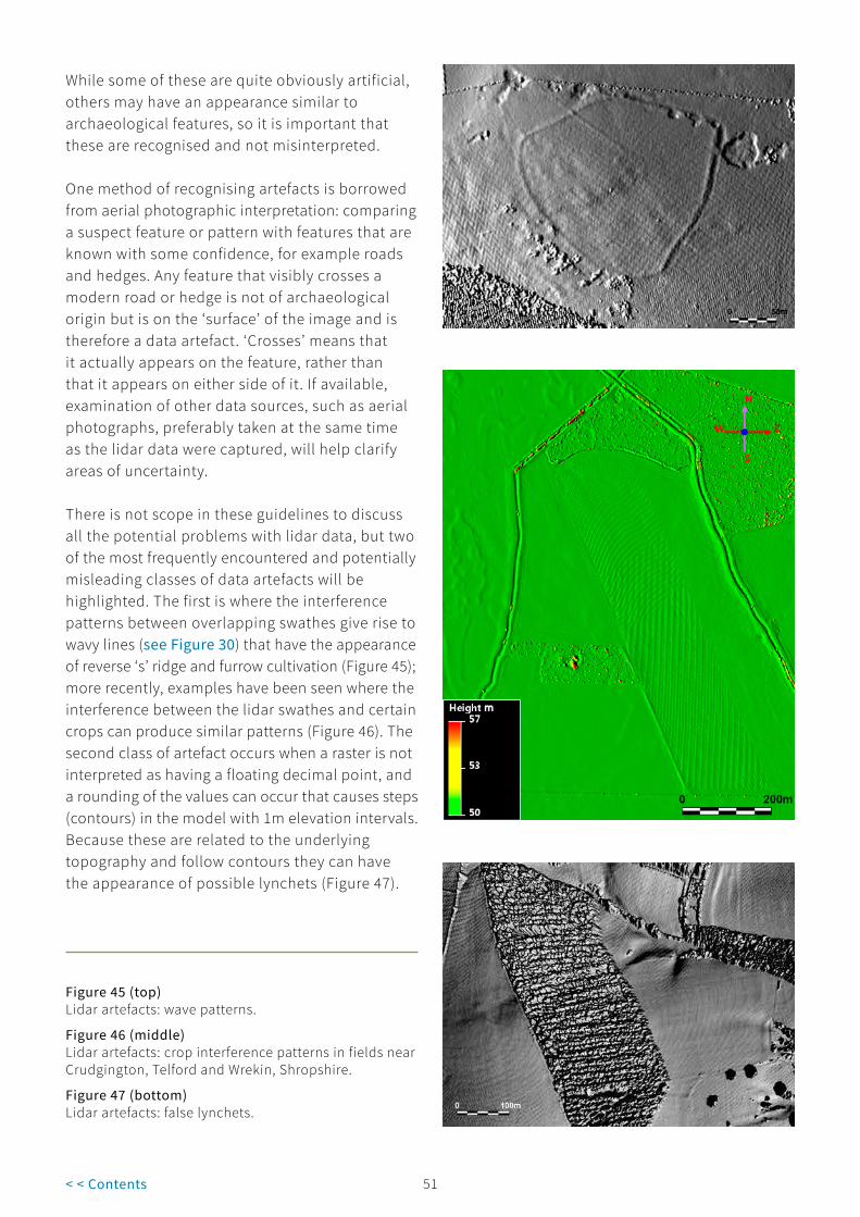
51< < Contents
While some of these are quite obviously artificial, others may have an appearance similar to archaeological features, so it is important that these are recognised and not misinterpreted.
One method of recognising artefacts is borrowed from aerial photographic interpretation: comparing a suspect feature or pattern with features that are known with some confidence, for example roads and hedges. Any feature that visibly crosses a modern road or hedge is not of archaeological origin but is on the ‘surface’ of the image and is therefore a data artefact. ‘Crosses’ means that it actually appears on the feature, rather than that it appears on either side of it. If available, examination of other data sources, such as aerial photographs, preferably taken at the same time as the lidar data were captured, will help clarify areas of uncertainty.
There is not scope in these guidelines to discuss all the potential problems with lidar data, but two of the most frequently encountered and potentially misleading classes of data artefacts will be highlighted. The first is where the interference patterns between overlapping swathes give rise to wavy lines (see Figure 30) that have the appearance of reverse ‘s’ ridge and furrow cultivation (Figure 45); more recently, examples have been seen where the interference between the lidar swathes and certain crops can produce similar patterns (Figure 46). The second class of artefact occurs when a raster is not interpreted as having a floating decimal point, and a rounding of the values can occur that causes steps (contours) in the model with 1m elevation intervals. Because these are related to the underlying topography and follow contours they can have the appearance of possible lynchets (Figure 47).
Figure 45 (top)Lidar artefacts: wave patterns.
Figure 46 (middle)Lidar artefacts: crop interference patterns in fields near Crudgington, Telford and Wrekin, Shropshire.
Figure 47 (bottom)Lidar artefacts: false lynchets.

51 52< < Contents
Another issue that can produce artefacts that are very disruptive to interpretation relates directly to the use of RVT (see section 4.1). If unfilled data are processed through the RVT then certain visualisations, especially openness visualisations, will create seriously distracting artefacts, as seen in Figure 48.
Summary � Like an aerial photograph, a lidar-derived
image can appear misleadingly simple to interpret; to ensure the best results from a survey the interpretation should be carried out by someone with the necessary skills and experience.
� There will be a significant cost benefit in detailed evaluation of the imagery before any field survey work is carried out.
� While lidar surveys can provide information not readily available from other sources, commissioning a full aerial photographic survey using both historic and modern photographs should be considered, as the interpretation process is made much
easier by comparing different sources. This is particularly appropriate for non-wooded landscapes but it can have benefits in wooded areas as well, as historic photographs may show features prior to planting or after clearance.
� Lidar has particular advantages over other aerial and ground-based survey techniques for wooded landscapes, because the use of algorithms to filter out vegetation makes it possible to record features beneath the woodland canopy.
� A processed bare-earth DTM provides the best results.
� As with all data sources, artefacts can be created during the original data collection and subsequent processing; while some of these are quite obviously artificial, others may appear similar to archaeological features and it is important that these are recognised and not misinterpreted.
Figure 48Lidar processing issues. Left: openness positive visualisation created with Relief Visualization Toolbox from a surface with holes. Right: openness positive visualisation created with Relief Visualization Toolbox with a surface processed to fill small holes.

53< < Contents
4.3 Mapping
Mapping is an essential part of archaeological survey using lidar. In order to record the results of lidar data interpretation adequately, it is almost always necessary to map the features identified; in fact experience has shown that the actual mapping process concentrates the mind and often clarifies the interpretation (F Small, Historic England, pers comm). Depending on the level of survey and the detail required, the same mapping conventions are used as in aerial and ground-based archaeological surveys. Normally, mapping will be carried out in a digital environment, but where interpretation is done in the field using paper copies of lidar imagery then the use of manual methods on transparent overlays may be appropriate.
The nature of lidar and laser-scanned data in general means that the majority of lidar packages are designed for viewing the data. The software enables you to view data in 3D, creating surface models that can be rotated, flown through, etc. Some programs are available, especially within the commercial sector, that are designed to extract data automatically from point clouds, for example when planning the presence of pipes in a refinery. Such programs have their uses, but the best packages for viewing the data are not necessarily the best for mapping and recording purposes.
To interpret features effectively, viewing software with full 3D functionality and the ability to create specialist visualisations that highlight microtopography, etc, is essential, but for mapping features compromises may need to be made. Until the development and testing of specialist visualisation software, the best method available was to use viewing software to produce a hillshaded raster image that could be used as a flat-base image within the mapping software. This was an effective method, especially when used with viewing software that allows real-time manipulation of the source data to aid interpretation, ie on-the-fly manipulation of a light source. New developments enable this same real-time manipulation within some GIS and computer-aided design (CAD) software, and hopefully
further developments will facilitate wider use of this technique. However, the provision of a much larger range of visualisations (see section 4.1 and in particular box 3), all of which are fully georeferenced and will therefore be accurately located within CAD or GIS software, has meant that it is a lot easier to analyse, interpret and, most importantly, map from lidar-derived data.
The 3D data can also be used in modern photogrammetric packages, viewed in stereo and mapped in 3D. The use of such software is still a specialised area, but may be worth considering for particularly important sites. Modern digital photogrammetry can produce high-resolution 3D datasets from traditional or modern digital photographs that are similar to the height data produced by lidar; such datasets can be used and manipulated in the same way as lidar data, producing the full range of specialist visualisations described in section 4.1, especially box 3.
It is important to remember that mapping a feature or features visible on lidar-derived imagery is only part of the recording process; it is crucial that, in addition to the graphical depiction of any given feature there is a database record as well. If the mapping is carried out within a GIS environment, it is possible to attach relevant data, such as suggested date and interpretation, along with additional sources, comments, etc. If you are not able to work in a GIS package, then these data need to be recorded in a separate database and some form of linkage made between the two datasets.
Summary � Mapping is an essential part of an
archaeological survey using lidar; in order to record the interpretive results adequately it is almost always necessary to map the features identified.
� It is important to remember that mapping a feature or features visible on lidar-derived imagery is only part of the recording process; it is crucial that, in addition to the graphical depiction of any given feature, there is also a database record.

53 54< < Contents
� Sound interpretations rely on expertise and experience and greatly benefit from the use of multiple data sources in combination with the lidar data.
4.4 Field use: hardcopy versus digital; raster versus vector
Historic England survey staff have compared the results of lidar analysis with field survey in projects in the Mendip Hills, Somerset, in mature, deciduous woodland in Savernake Forest, Wiltshire, and in the upland landscape of the North Pennines AONB. This work confirmed the accuracy and increased efficiency of recording using lidar data. So far, much of the work using lidar for archaeological investigation in the field has centred on its use in woodland. It has been seen as a technique particularly suited for surveying in an environment that has previously proved very difficult to work in.
One of the key issues relating to survey in woodland before the advent of lidar was speed. Because of the nature of woodland, in which features may be obscured by the presence of trees and even more by undergrowth, previously projects usually employed ‘walkthrough’ surveys, in which transects of varied width were used (Rotherham et al 2008, section D). In order to maximise a survey, particularly given the short timeframe during which vegetation is at a sufficiently low level to not impede study, one option is to use large numbers of trained volunteers. Using this methodology to check features on the ground against lidar-derived imagery, the emphasis has been on using hardcopy printouts. There are many advantages to using such plots in the field, especially the lack of a need for any complex hardware or software. A sheet of A3 paper with a specialist visualisation can provide suitable reference material to which notes can be added as observations are made. This is arguably the most effective technique in open landscapes as well. Even when fieldwork is planned there is benefit in carrying out a more detailed desktop survey using lidar and other data sources (eg standard aerial photographs), and
taking this information into the field instead of, or together with, the simple lidar-derived imagery. Similarly, the results of field survey can feed back into further analysis of the original datasets on a computer.
Historic England staff have carried out a number of projects using lidar data in the field across a variety of landscapes.
Extensive uplands:
� North Pennines AONB (Knight et al 2012) http://research.historicengland.org.uk/Report.aspx?i=15078
� National Archaeological Identification Survey (NAIS), uplands (Oakey et al 2015) (see case study 5) http://research.historicengland.org.uk/Report.aspx?i=15321
Lowland areas:
� NAIS, Wiltshire (Last et al 2016) http://research.historicengland.org.uk/Report.aspx?i=15530)
Woodland:
� Cannock Chase, Staffordshire (see case study 1)
The lidar data were loaded into navigation-grade GNSS devices (Figure 49), but primarily they were used as hardcopy printouts. Similarly data, and more specifically specialist visualisations, have been used by large numbers of volunteers as part of HLF projects, including Secrets of the High Woods, South Downs (see case study 2), and New Forest Remembers, Hampshire, and on training courses. These projects used both hardcopy printouts and handheld tablet devices (Figure 50). The experience of these projects, both within Historic England and the wider sector, indicates that there is great potential for more rapid surveys in a number of different environments.

55< < Contents
Figure 49Using lidar data on the handheld GNSS.
Figure 50Teaching with lidar data on a rugged tablet.
Summary � Field checking has confirmed the accuracy
of desk-based interpretation and mapping based on lidar data.
� Field checking is an iterative process that feeds back to those carrying out desk-based surveys and increases understanding and interpretation skills.
� Specialist visualisations can be produced and taken into the field; a specialist visualisation printed on a sheet of A3 paper can provide suitable reference material to which notes can be added as observations are made.
� Even when fieldwork is planned, there is benefit to carrying out a more detailed desktop survey using lidar and other data sources, such as standard aerial photographs and historic mapping, and taking this information into the field, perhaps with the lidar-derived imagery.

55 56< < Contents
5 Woodland Survey
While aerial survey of most types of landscape has dramatically increased our understanding of the historic landscape, woodland has always hindered this process, preventing a clear view of any archaeological evidence hidden beneath (Figure 51). Prior to lidar surveys, the history of many UK woodlands was usually poorly understood, and as such they have been referred to as one of the UK’s last untapped archaeological resources. Woodland also presents its own unique set of problems for ground-based survey techniques,
and is one of the most difficult landscapes in which to work (Bowden 1999, 134-9; Oswald et al 2008). The arrival of lidar, with its capacity to strip away the bulk of the vegetation and reveal the features underneath, has proved to be of great benefit (Figure 52), but it is not without limitations.
Figure 51A typical aerial photograph of a large hillfort hidden beneath a woodland canopy.
Figure 52A lidar-modelled ground surface of the same area shown in Figure 51.
One of the key difficulties with the process is the fact that lidar is indiscriminate in what it records. It is important, wherever possible, to have an

57< < Contents
alternative source of data to aid the interpretation of features. This is especially true in woodland, particularly in managed forestry, because there are several processes that create features that can easily be mistaken for archaeological remains. Unfortunately, the nature of woodland means that, for much of it, the alternative source of aerial photography is limited to open phases during the management of forest or shows nothing below the top of the canopy. It is therefore a prerequisite to understand the types of features that might be seen in woodland, and also the effects that different planting and management regimes might have on the results of a survey. Knowledge is also needed of the limitations to what the technology can show and the types of woodland in which it is best employed.
5.1 Survey suitability
To gain the most from any lidar survey commissioned for historic environment analysis, the surveys should be flown at a higher resolution than that required for open ground, and during the winter months when laser beam penetration to the forest floor should be maximised. Many existing lidar data may not be optimal for analysis, for example if they were collected during the summer or were not captured at a high-enough resolution. When considering a new survey, it should be borne in mind that not all wooded areas are suitable for lidar, and that, where it is to be applied, data capture and processing needs to be specified beforehand to ensure the best possible products and value for money.
Because the survey is dependent upon laser penetration of the forest canopy and understorey vegetation, significant areas of dense, young woodland regeneration or unthinned conifer plantation will greatly restrict the potential of the survey and may prevent it from being a viable option (see below).
Lidar technology facilitates the survey of large areas of forest- and woodland-dominated landscapes. The best results are obtained with mature broadleaf canopy with little understorey
vegetation, for example a beech woodland with small annual understorey plants such as bluebells, where a winter survey should ensure that the vast majority of the laser pulses will reach the forest floor uninhibited. Under these optimum conditions, surveys can reveal detailed changes in ground surface and reveal many subtle archaeological features. The method is most effective at revealing linear features and even faint earthworks, many of which may be difficult to see on the woodland floor. Examples include earthworks of enclosures (Figure 53), field systems, boundary banks, lynchets, route-ways and drainage channels. When used over optimum vegetation types, smaller, more discrete features, such as charcoal platforms and saw pits, have been mapped (Figure 54).
Young, dense conifer plantations will greatly reduce the quantity of energy able to penetrate to the forest floor (Figure 55). Even where canopy penetration is perceived to be good, dense layers of understorey vegetation, such as bramble, bracken, gorse or holly, can still inhibit the laser beam from reaching the true ground surface (Crow 2007). Indeed, gaps in lidar-derived DTMs caused by understorey holly have been used to map its distribution across parts of the Ironbridge Gorge World Heritage Site, Shropshire.
While customising the specification for a lidar survey of a wooded area can increase the likelihood of the laser beam finding any gaps in the vegetation, dense canopy or understorey will still prevent most of the laser energy from reaching the woodland floor. As shown in the examples in Figures 53-55, some features may be discernible from a few data points, but this will not always be the case and knowing where data quality is reduced can be difficult to identify in a DTM where any gaps have been filled and smoothed. Furthermore, the quality assurance (QA) statistics that are provided for a survey as a whole will not necessarily be representative of a given area. Such areas can be significantly large and an absence of any archaeology shown in the processed DTM may not be a true representation of the survival of features (Figures 56 and 57). To identify such areas, the data can

57 58< < Contents
be processed to produce DTMs that are unfilled, mask layers detailing the areas devoid of ground hits can be created or the point clouds can be examined to show where ground returns are absent. Alternatively, other sources of vegetation information can be used to highlight any problem areas. Knowledge of the vegetation types through which the survey is expected to work is essential when considering potential areas for lidar survey, in order to target efficient use of resources and provide confidence in the resulting data interpretation.
While lidar has revealed such discrete features as saw pits, there is no guarantee that all features of a similar size will be resolved, especially if data processing has filled or smoothed the DTM during its creation. An additional problem with the identification of small features is that, while the lidar system may have detected them, they may only be displayed by a few pixels in the resulting image and distinguishing them from any noise or patches of vegetation can be difficult.
Figure 53 (top left)An example of a hilltop enclosure within woodland visible on lidar..
Figure 54 (middle left)Examples of circular charcoal platforms in woodland visible on lidar..
Figure 55 (bottom left)Examples of the effects that different types of vegetation have on lidar surveys.
5.2 Identifying features in woodland
Hillshaded images will show not only archaeological features but roads, paths, buildings and, specifically pertinent to woodland survey, forest residue, timber stacks and a host of other modern objects (Figure 58). Additionally, changes in ground vegetation can create patterns that look like features of archaeological potential (Figure 59). Distinguishing between the genuine historic environment and features with a more recent origin is therefore an important and necessary process, and can be a long-term project for survey areas of significant size.
The ability to place lidar specialist visualisations into GIS means that other layers can be overlain. Aerial photographs and modern and historic maps can be placed over visualisation images, but spatial forest management data may also identify many features, such as loading bays or planned recreational areas, and can provide an indirect explanation for others. This process may help to eliminate many objects and draw attention to those remaining.
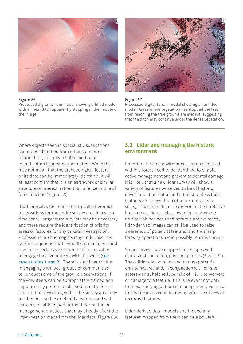
59< < Contents
Where objects seen in specialist visualisations cannot be identified from other sources of information, the only reliable method of identification is on-site examination. While this may not mean that the archaeological feature or its date can be immediately identified, it will at least confirm that it is an earthwork or similar structure of interest, rather than a fence or pile of forest residue (Figure 58).
It will probably be impossible to collect ground observations for the entire survey area in a short time span. Longer term projects may be necessary and these require the identification of priority areas or features for any on-site investigation. Professional archaeologists may undertake this task in conjunction with woodland managers, and several projects have shown that it is possible to engage local volunteers with this work (see case studies 1 and 2). There is significant value in engaging with local groups or communities to conduct some of the ground observations, if the volunteers can be appropriately trained and supported by professionals. Additionally, forest staff routinely working within the survey area may be able to examine or identify features and will certainly be able to add further information on management practices that may directly affect the interpretation made from the lidar data (Figure 60).
Figure 56Processed digital terrain model showing a filled model with a linear ditch apparently stopping in the middle of the image.
Figure 57Processed digital terrain model showing an unfilled model. Areas where vegetation has stopped the laser from reaching the true ground are evident, suggesting that the ditch may continue under the dense vegetation.
5.3 Lidar and managing the historic environment
Important historic environment features located within a forest need to be identified to enable active management and prevent accidental damage. It is likely that a new lidar survey will show a variety of features perceived to be of historic environment potential and interest. Unless these features are known from other records or site visits, it may be difficult to determine their relative importance. Nonetheless, even in areas where no site visit has occurred before a project starts, lidar-derived images can still be used to raise awareness of potential features and thus help forestry operations avoid possibly sensitive areas.
Some surveys have mapped landscapes with many small, but deep, pits and quarries (Figure 61). These lidar data can be used to map potential on-site hazards and, in conjunction with on-site assessments, help reduce risks of injury to workers or damage to a feature. This is relevant not only to those carrying out forest management, but also to anyone involved in follow-up ground surveys of recorded features.
Lidar-derived data, models and indeed any features mapped from them can be a powerful

59 60< < Contents
tool for forest design planners. Because the survey produces 3D surface models of a forest, which can be manipulated within mapping software, forest views can be examined and planned from all angles (Figure 62). This has the benefit of revealing archaeological features as they may once have looked in an earlier landscape, and makes it possible for planners to consider possible visual connections associating historic environment features within the landscape, or to change the setting of individual features. Recreational access routes to and around historic environment features can be sensitively planned
to increase their value and profile within the woodland, thereby enhancing its cultural value. This is equally true for non-wooded environments, such as the restoration of quarries, where reinstatement schemes that seek to create new wildlife and wetland habitats incorporate new footpaths and routes for the public. These can also take in historic environment features that may lie just outside (or be truncated by) a quarry. It is then possible to have display boards that link the newly created environment with the original/historic environment.
Figure 58 (top left)Example of false earthworks: bracken fallen over a wire fence during winter can resemble an earthwork in the processed data.
Figure 59 (bottom left)Example of false earthworks: this apparent mound is caused by a dense growth of rhododendron.
Figure 60 (top right)Simple photographic evidence taken during routine site work can be very informative for feature identification and management.
Figure 61 (bottom right)Lidar-derived models can be useful in mapping difficult terrain.

61< < Contents
Lidar data and modelled outputs have potential uses in many areas. For example, the differences between a DSM and DTM can be used to produce a map of vegetation height. Models of the forest canopy can be used to map individual trees, although this works best on well-thinned or mature woodland, where there are differences in tree height or shape as a result of a change in species or establishment date. These models can be useful in identifying and mapping the health, structure and distributions of ancient woodland or veteran trees within younger plantations (Figure 63). Hedgerows and small areas of woodland can also be mapped to show ecological corridors. When a survey is carried out over mature broadleaf woodland with little understorey, there should be little to prevent the laser beam from reaching the forest floor. Under such conditions the large boles of any ancient trees present (standing or fallen) can block the laser beam, and thus be mapped.
High-density point clouds are now routinely obtained and can provide useful structural and monitoring information on aspects of living heritage, such as ancient or significant trees. These data can be retained for future reference and comparison (Figure 64). With further developments in lidar technology, it may soon be possible to map dead wood, understorey and, eventually, full forest structure, with potential applications in biomass calculations and carbon storage.
Lidar is a very powerful tool and when applied to suitable wooded landscapes has the potential to map both known and previously unrecorded historic environment features. These surveys can provide information about a woodland’s history and, in turn, guide its future management. Nonetheless, lidar is not an instant solution that can reveal every aspect of a woodland’s heritage, and it is best employed in combination with other sources of information. It is most economical to apply the technique at a landscape scale, so the cost of commissioning surveys can be considerable. However, such surveys should be looked upon as a long-term investment, because the data, models and images can be useful for planning, management and public engagement.
Figure 62 (top)A 3D model with an aerial photograph draped over it can be a very useful planner’s tool.
Figure 63 (middle)Veteran trees that have received a ‘halo-thin’ (localised management to remove competition from surrounding trees).
Figure 64 (bottom)A view of three parkland trees generated from an airborne laser survey commissioned for heritage mapping.

61 62< < Contents
Summary � Lidar has the potential to provide an
unequalled means of recording within wooded areas.
� Significant areas of dense, young woodland regeneration or unthinned conifer plantation will greatly restrict the potential of a lidar survey and may actually prevent it from being a viable option.
� The best results are obtained from mature broadleaf canopy with little understorey vegetation.
� Lidar is effective at revealing linear features, and even very subtle earthworks can be shown, such as field systems, lynchets, boundary banks and trackways.
� DTM-derived images will not only show archaeological features but also roads, paths, buildings, forest residue, timber stacks and other modern objects.
� Changes in ground vegetation can create patterns that look like features of archaeological potential.
� DTM-derived images can be used to raise awareness of potential features and enable forestry operations to avoid possibly sensitive areas.Lidar data can provide a potential map of on-site hazards and can be used in conjunction with on-site assessments to help reduce the risk of injury.
� Lidar data can be used to help planners design recreational access routes to and around historic environment features, to increase their value and profile within the woodland and thereby enhance its cultural value.
� Lidar can help with the mapping of veteran trees and other aspects of natural heritage.
� Knowing what vegetation occurs within a survey area is important for the interpretation of results and understanding data limitations.
� An understanding of survey specification and data-processing methods is more important for wooded landscapes than other lidar surveys.

63< < Contents
6 Conclusions
Although lidar is a relatively well-established technique, it has only been used for archaeological research in the UK since the turn of the 21st century. It primarily measures 3D data, and is effective for recording features that exhibit some form of surface topographic expression. The exception to this is intensity data, which can be used to analyse the reflectivity of the surface being hit by the laser beam and thus, in certain circumstances, can aid interpretation in a similar way to cropmarks on traditional aerial photographs.
The accuracy and resolution of lidar data are heavily dependent on the method of capture and the level of processing before they reach the end-user. Standard airborne lidar generally has an absolute accuracy of about 100-150mm, with an even higher relative accuracy. From an archaeological point of view, relative accuracy is often more important than absolute accuracy because it is the relative position of features that makes it possible to record them and to understand their relationships with other features.
When planning any sort of archaeological survey for which lidar may be useful, advice on many aspects of the process and surveying in general can be sought from Historic England (see section 9.1.1). If the survey area consists largely of woodland, Forest Research can also provide technical advice and guidance (see section 9.1.2).
It is essential that all issues relating to dissemination, archiving and copyright are considered at the outset of a project, to ensure clarity regarding which data and imagery can be published and made available to others. Lidar data files and generated imagery are generally quite large and as such they are not easily supplied to third parties. It is important to be clear about whether the lidar data are required
as a primary data source or whether they are going to be used as a background layer for other datasets available elsewhere. If what is required is basic height data at scales suitable for general topographic relief, these may be available from alternative sources, for example the OS or NASA (see section 3.1.2). If more detailed data are required you need to assess whether such data for your area of interest already exists. The EA has flown large areas of the country as part of its work monitoring flood risk, etc, and a large number of lidar surveys are carried out by various companies each year for non-archaeological purposes, such as infrastructure planning (see section 3.4).
One of the key issues that affects the viability of lidar is the land use of the area to be surveyed. Lidar primarily records 3D data, and therefore requires a topographic surface expression for features to be revealed; the better the earthwork survival, the better the results. While lidar will work in most landscapes, it provides an unequalled means of recording archaeological earthworks within wooded areas. The best results are obtained from mature broadleaf canopy with little understorey vegetation; significant areas of dense, young woodland regeneration or unthinned conifer plantation will greatly restrict the potential of the survey and may mean lidar is not a viable option. To achieve sufficient canopy penetration, survey in woodland requires a higher point density in the original data than in an open landscape, and winter flights. The development of FWF lidar and higher pulse rates means much more accurate recoding of ground surfaces within wooded and other heavily vegetated environments is now possible.
If new data are required then 3D Laser Scanning for Heritage (Historic England 2018) should be consulted, as many of the issues

63 64< < Contents
of commissioning a laser scanning survey are addressed in it. For predominantly wooded landscapes, advice can be sought from Forest Research (see section 9.1.2). When considering the project area, large, rectangular or linear survey areas are the most cost effective, because they have the minimum number of turns at the end of each aircraft run; small or irregularly shaped areas are the least cost effective.
Make sure that you know the actual form of data that will be provided; it is no good if the data provided by a contractor is in a format that you or any other end-user cannot use. The methodology of projects that will benefit from lidar data will vary in detail, but in many cases the extensive dataset provided by lidar is best treated initially as a data source for a desktop survey. The quality of interpretation and metrical accuracy possible from lidar (used in conjunction with aerial photographs and other sources) gives a high degree of confidence in the results and makes it possible to target fieldwork carefully.
Like an aerial photograph, a lidar-derived image can appear misleadingly simple to interpret; to ensure the best results from a survey the interpretation must be done by someone with the necessary skills and experience. For predominantly non-wooded landscapes, commissioning a full aerial survey using both historic and modern photographs should be considered, as the interpretation process is made much easier by comparing different sources.
Lidar data can be used in many formats; the standard digital product from a lidar survey is likely to be an ASCII grid, which can be used in standard GIS with add-on modules or specialist 3D viewing programs. Ideally the 3D data should be viewed stereoscopically, taking advantage of the brain’s natural ability to interpret 3D objects, but if the end-user does not have the facilities to view and manipulate the original data in a specialist package, it is still possible to use 2D snapshots of the data as standard JPEG or TIFF files. The most obviously user-friendly product is the hillshaded image, which can be lit from any conceivable position. Other visualisations,
including PCA and slope models, can also be of use (see section 4.1).
Mapping is an essential part of archaeological survey using lidar; in order to record the results adequately it is almost always necessary to map the features identified and accompany this with a database record. Even where fieldwork is intended, it can be beneficial to carry out a more detailed desktop survey using lidar data and other sources, such as standard aerial photographs, and taking this information into the field instead of, or together with, the simple lidar-derived imagery.
In summary, lidar can be an extremely useful tool when used in appropriate circumstances, particularly when it is used alongside other data sources. Lidar cannot reveal all the feature types that can be recorded by other means, and in certain cases the results may be largely uninformative, but when used in a suitable environment the results can be spectacular.

65< < Contents
7 Case Studies
7.1 Case Study 1 – Industrial remains on Cannock Chase, Staffordshire
Cannock Chase, Staffordshire, is an Area of Outstanding Natural Beauty (AONB) situated to the north of Birmingham. The Chase occupies an elevated plateau and is a combination of woodland, largely conifer plantations but some broadleaf species, and heathland, with bracken, heather, gorse and bilberry.
Historic England, in collaboration with Staffordshire County Council and the AONB with funding from the Heritage Lottery Fund (HLF), undertook an archaeological survey of the Chase. Entitled The Chase through Time, the project considered all the archaeological remains visible from the air within a date range from the Neolithic to the 20th century. In a largely wooded and overgrown landscape such as the Chase, lidar was the primary source of information, supplemented by evidence seen on aerial photographs. The project commissioned a lidar survey at 0.25m resolution together with an aerial photographic survey producing orthophotos. Interpreters created a range of visualisations at 0.25m resolution using the Relief Visualization Toolbox (RVT). These were loaded into AutoCAD® for analysis, interpretation and mapping.
Historic England undertook this project during the First World War centenary commemorations, and its main impetus was to gain a better understanding of the remains of two large First World War training camps on Cannock Chase. However, another strand in the history of the Chase is its industrial past and, in particular, its long history of coal mining, which extends back to the Middle Ages. There is documentary evidence of coal mining on the Chase from the 13th century, and the final pit closed in 1993. Earlier mining remains, in the form of pits and small spoil heaps,
survive well, but they are largely situated within woodland in the southern half of the Chase. Although many of these can be seen from paths that cut across this part of the Chase, many more are off the beaten track hidden within the woods. A good example of this is Brereton Hayes Wood, situated towards the northern end of the Cannock coalfield, where lidar has revealed a large number of coal mining remains. At the northern end of this group is a band of closely spaced pits that have no clearly defined spoil heaps. Elsewhere, spoil heaps often partially or totally encircle each mineshaft, indicating deeper workings.
For this particular aspect of the archaeological remains, the most useful visualisations were a combination of 16-direction multi-hillshade (16D) (Figure CS1.1). and openness positive (OP) (Figure CS1.2). OP was preferred for the identification and mapping of the mineshafts because it defined each pit as a black circle that sharply contrasted with the surrounding area. It also resolved some areas of uneven ground seen in the other visualisations into slight circular depressions. In contrast, the associated spoil heaps were invariably less clearly defined in OP than in 16D, and there were some examples where a low spoil heap was almost impossible to identify with OP.
Another interesting element with regard to the lidar data from this area was the use of filled and unfilled surfaces (see section 4.2.2). The lidar from which the observations and mapping were made were filled, but only to the extent of processing to fill small gaps. Larger areas were left unfilled to represent the lack of returns. Brereton Hayes Wood consists largely of coniferous plantation that, together with patches of dense vegetation on the heathland, resulted in numerous holes. These were often very closely spaced and suggested some areas had very little data. In order to run the data

65 66< < Contents
Figure CS1.1 (top)Cannock, Staffordshire, 16-direction multi-hillshade.
Figure CS1.2 (bottom)Cannock, Staffordshire, openness positive.

67< < Contents
through the RVT (see section 4.1), it was necessary to process the data further to remove any gaps that might cause issues with the visualisations (see section 4.2.3). This processing revealed the presence of swathes of coal pits in areas where there appeared to be no data (Figure CS1.3).
Areas where previous fieldwork had been undertaken allowed some comparison to be made between what was seen on the ground and what was seen with lidar. Initial observations indicated a good degree of accuracy of filled lidar in correctly representing coal pits. This raised the question of how there could appear to be information in areas where there are apparently no data. The answer would appear to be twofold: firstly, it is remarkable how few points are needed to obtain at least a coarse impression of a feature; secondly, and perhaps more importantly, it depends on how we see things. When gaps are shown in black, your eyes tend to get distracted by the strong contrast and just see the gaps,
whereas if the gaps are filled you actually focus on the features that are defined. Whatever the reason, in this case the combination of different visualisations produced a record of the rich industrial remains still present. This is not to say that the technique will always be effective, and does not negate the vital importance of knowing where gaps are, as discussed in section 4.2.2.
The Chase was once a major coal-producing area but, with the demolition of the last collieries, the legacy of this industry is obscured. The remains of early coal mining are elusive, with old maps offering only sparse references to ‘coal pits’. The lidar survey has enabled the creation of a detailed map of the remains of this important industry and, by highlighting the survival of the shafts and spoil heaps, provides a tangible link with the industrial past of this part of Staffordshire (Carpenter et al 2018).
Figure CS1.3Cannock, Staffordshire, original unfilled surface.

67 68< < Contents
7.2 Case Study 2 – Secrets of the High Woods, South Downs National Park Authority, Hampshire and Sussex
From 2014 to 2016, the South Downs National Park Authority (NPA) hosted a major Heritage Lottery Fund (HLF) research and community engagement project: the Secrets of the High Woods. The project was designed to investigate and explore a large area of the national park’s archaeological landscape using high-resolution lidar.
The South Downs have been at the heart of archaeological research in south-east England for centuries. However, while the open chalk
downlands have been at the forefront of much of the research, a comprehensive survey of the archaeological landscapes to the north of Chichester has been hampered by the presence of extensive woodland cover.
The potential of the landscape had long been recognised by local archaeological teams. Detailed survey was required, and lidar identified as an ideal technique. A 0.25m resolution lidar dataset and range of specialist visualisations were commissioned by the Secrets of the High Woods project (Figure CS2.1), providing a spectacular insight into the archaeological topography of the study area. The survey demonstrated that, in contrast to many other areas of chalk downland that have been subject to plough damage, an extensive archaeological landscape remained well preserved beneath the woodland canopy.
Figure CS2.1Bignortail Wood, West Sussex, reveal (clockwise from top left: Bignortail wood as seen on aerial photography; single hillshade 315°; openness positive; local relief model.

69< < Contents
A National Mapping Programme (NMP) survey was undertaken on behalf of the project by Historic England and Cornwall County Council, to provide a baseline quantification and qualification of the archaeological resource. A bespoke content management system was developed that enabled data to be hosted and accessed via a central web interface. This database underpinned an exciting method of undertaking NMP surveys, enabling the concurrent digital transcription and interpretation of features by multiple users, with simultaneous access to a host of complementary historic environment resources. It also provided the foundation for the development of a digital field recorder, allowing volunteer records, photographs and observations to be captured and made available to professional teams.
The project attracted a large support base, with teams of volunteers undertaking fieldwork and archival research to aid in the interpretation and identification of the archaeological topography. A range of lidar visualisations was provided for
participants while out in the field, with the digital recording system facilitating exploration of the data alongside complementary resources such as historic cartography, historic environment records and the NMP transcriptions (Figure CS2.2). Technical training, guided walks, tours, workshops and community excavations helped to build the depth of volunteer experience.
This community-based project is part of a long history of archaeological exploration and research within the South Downs. The data proved to be a great tool for community participation in exploring the heritage of the national park, and in developing public understanding of the evolution of this stunning historic landscape. The project has provided a springboard for research, and raised technical understanding and interest in airborne laser survey that will continue to promote investigation into the historic environment of the area for years to come. To view some of the spectacular discoveries, see Carpenter et al (2016).
Figure CS2.2Volunteers with the Secrets of the High Woods Project (clockwise from top left: Planning the survey; recording features with a tablet; measuring a feature with poles and tape; inputting data on the tablet.
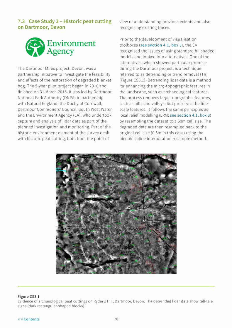
69 70< < Contents
7.3 Case Study 3 – Historic peat cutting on Dartmoor, Devon
The Dartmoor Mires project, Devon, was a partnership initiative to investigate the feasibility and effects of the restoration of degraded blanket bog. The 5-year pilot project began in 2010 and finished on 31 March 2015. It was led by Dartmoor National Park Authority (DNPA) in partnership with Natural England, the Duchy of Cornwall, Dartmoor Commoners’ Council, South West Water and the Environment Agency (EA), who undertook capture and analysis of lidar data as part of the planned investigation and monitoring. Part of the historic environment element of the survey dealt with historic peat cutting, both from the point of
view of understanding previous extents and also recognising existing traces.
Prior to the development of visualisation toolboxes (see section 4.1, box 3), the EA recognised the issues of using standard hillshaded models and looked into alternatives. One of the alternatives, which showed particular promise during the Dartmoor project, is a technique referred to as detrending or trend removal (TR) (Figure CS3.1). Detrending lidar data is a method for enhancing the micro-topographic features in the landscape, such as archaeological features. The process removes large topographic features, such as hills and valleys, but preserves the fine-scale features. It follows the same principles as local relief modelling (LRM; see section 4.1, box 3) by resampling the dataset to a 50m cell size. The degraded data are then resampled back to the original cell size (0.5m in this case) using the bicubic spline interpolation resample method.
Figure CS3.1Evidence of archaeological peat cuttings on Ryder’s Hill, Dartmoor, Devon. The detrended lidar data show tell-tale signs (dark rectangular-shaped blocks).

71< < Contents
This smoothed elevation dataset is subtracted from the original elevation dataset and viewed using a standard deviation stretch that ignores high values to enhance the fine-scale features in the landscape.
This technique proved particularly successful in highlighting areas of historical peat cutting,
features that are often difficult to recognise using traditional methods. Peat cuttings generally look like rectangular impressions in the landscape (Figure CS3.2). The detrended lidar data were viewed at a scale of 1:3000, and polygons were drawn around blocks of land where this characteristic effect was observed.
Figure CS3.2Polygons drawn around areas thought to be historic peat cutting sites on Dartmoor, Devon, based on evidence observed in detrended lidar data.
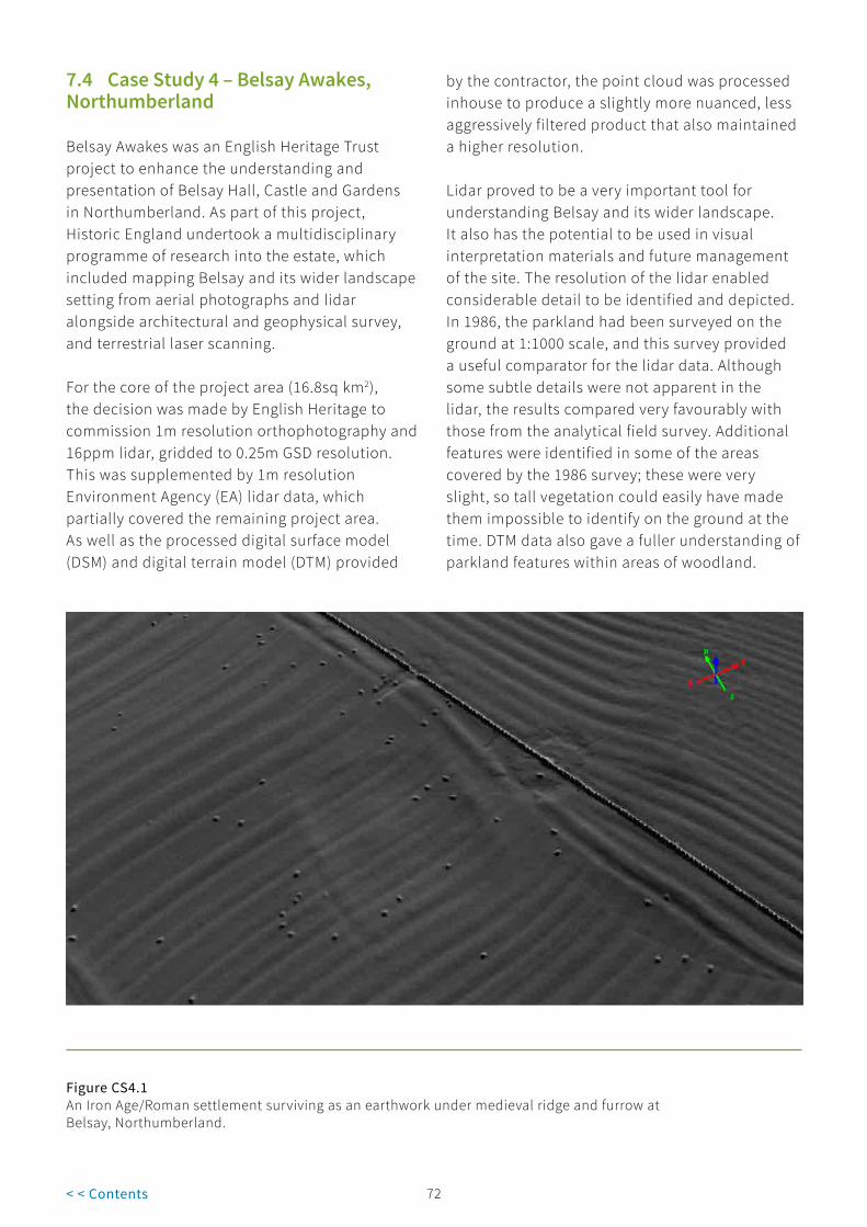
71 72< < Contents
7.4 Case Study 4 – Belsay Awakes, Northumberland
Belsay Awakes was an English Heritage Trust project to enhance the understanding and presentation of Belsay Hall, Castle and Gardens in Northumberland. As part of this project, Historic England undertook a multidisciplinary programme of research into the estate, which included mapping Belsay and its wider landscape setting from aerial photographs and lidar alongside architectural and geophysical survey, and terrestrial laser scanning.
For the core of the project area (16.8sq km2), the decision was made by English Heritage to commission 1m resolution orthophotography and 16ppm lidar, gridded to 0.25m GSD resolution. This was supplemented by 1m resolution Environment Agency (EA) lidar data, which partially covered the remaining project area. As well as the processed digital surface model (DSM) and digital terrain model (DTM) provided
by the contractor, the point cloud was processed inhouse to produce a slightly more nuanced, less aggressively filtered product that also maintained a higher resolution.
Lidar proved to be a very important tool for understanding Belsay and its wider landscape. It also has the potential to be used in visual interpretation materials and future management of the site. The resolution of the lidar enabled considerable detail to be identified and depicted. In 1986, the parkland had been surveyed on the ground at 1:1000 scale, and this survey provided a useful comparator for the lidar data. Although some subtle details were not apparent in the lidar, the results compared very favourably with those from the analytical field survey. Additional features were identified in some of the areas covered by the 1986 survey; these were very slight, so tall vegetation could easily have made them impossible to identify on the ground at the time. DTM data also gave a fuller understanding of parkland features within areas of woodland.
Figure CS4.1 An Iron Age/Roman settlement surviving as an earthwork under medieval ridge and furrow at Belsay, Northumberland.

73< < Contents
The Belsay landscape we see today has been heavily shaped by the influence of the estate but traces of earlier settlement and farming do survive. In some areas, extensive remains of medieval open fields could be traced. High-resolution lidar enabled subtleties in phasing and morphology to be identified, along with later enclosure boundaries.
Before the project commenced seven enclosures or settlements of probable Iron Age or Roman date were known, but lidar was an invaluable tool for identifying further sites, including a very denuded settlement and a probable promontory fort, both of which were not visible on available
aerial photographs. One of the most striking discoveries was a well-preserved rectilinear settlement enclosure underlying medieval ridge and furrow ploughing (Figure CS4.1 ).
Outside the formal parkland, a particularly significant find was the remains of a probable medieval park pale, the bank and ditch feature marking the boundary of the park (Figure CS4.2). Although its presence was suspected, no physical trace of it had ever been identified from the air or on the ground. Close analysis of the lidar visualisations identified large segments of the pale; lidar was therefore key to its identification and interpretation.
Figure CS4.2Traces of a probable medieval park pale surviving as a low bank (the course of the pale indicated by the white arrows) at Belsay, Northumberland.

73 74< < Contents
7.5 Case Study 5 – National Archaeological Identification Survey: upland pilot, Cumbria and Lancashire
The National Archaeological Identification Survey (NAIS) upland pilot project examined a landscape transect in north-west England, running from the Arnside and Silverdale Area of Outstanding Natural Beauty (AONB), Cumbria, in the west to the uplands of the Pennine fringe, Lancashire, in the east. Within this area, archaeological features are almost exclusively identified from the air as earthworks. Analysis of Royal Air Force (RAF) photography from the 1940s indicated that very little has been levelled in the post-war
years, largely because of the predominance of pasture. This landscape is therefore ideally suited to survey with lidar. The NAIS project began with mapping an area of 174 km2 from aerial photographs and lidar. The results from this were then used to target ground-based investigations, including field survey, geophysical survey, targeted excavation and palaeoenvironmental work.
Around 70% of the project area was covered by 1m resolution Environment Agency lidar, with smaller additional areas at 2m resolution (Figure CS5.1).
Figure CS5.1Extent of Environment Agency lidar data used for the National Archaeological Identification Survey upland project area.
The extent of coverage, coupled with the fact that the vast majority of the area was unwooded,

75< < Contents
meant that it was considered unnecessary to commission a new survey. Lidar data were supplied as gridded ASCII files, which were processed in-house using 16-direction hillshade (16D) and principal components analysis (PCA). Over 80% of the features recorded by the project were mapped from lidar; this percentage is even higher if those areas without lidar coverage are excluded. In part, this reflects the ease of using a georeferenced dataset, but features were also often better defined on lidar than the available aerial photographs.
The most extensive archaeological remains were identified in the east of the project area, particularly along the Lune Valley. This is an area that was known to contain well-preserved
settlements and field systems dating from the later prehistoric and Roman periods, but lidar was instrumental in creating a comprehensive record. Six previously unrecorded settlements were identified within the valley, including some heavily denuded sites that were very difficult to identify from the available aerial photographs.
Figure CS5.2Hillshaded lidar image overlain with National Mapping Programme data to show the location of charcoal-burning platforms in Barbon Park, Cumbria.
Aerial mapping was used as the basis for selecting sites for rapid walkover survey. Geographical information system (GIS) shapefiles were taken into the field on handheld global navigation satellite system (GNSS) devices to assess the accuracy of depiction and add additional details on phasing, function and chronology. The spatial accuracy and level of detail afforded by the lidar meant that this was an efficient process, enabling

75 76< < Contents
ground surveyors to locate sites easily and make judgements on how well the mapping reflected site morphology.
A small subset of sites was targeted for invasive investigation, including excavation, palaeoenvironmental work and scientific dating. These included a series of 34 charcoal burning platforms, which were identified from lidar in
a steep-sided valley at Barbon Park, Cumbria (Figure CS5.2 ). Some platforms were located on a bracken-covered south-facing slope, while others were situated within woodland. A combination of ground cover, aspect and the quality of existing aerial photographs meant that the platforms were largely only visible from lidar. The resulting mapping was used to target ground-based survey and excavation (Hazell et al 2017).
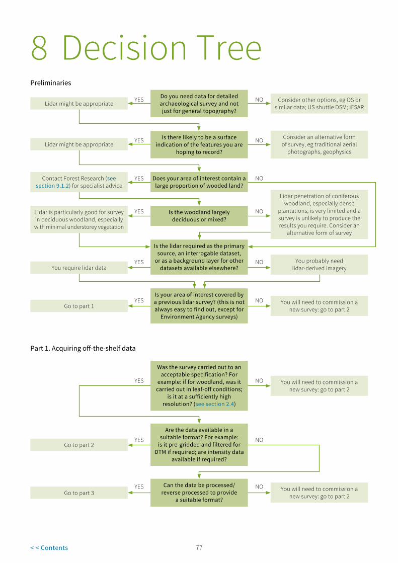
77< < Contents
8 Decision TreePreliminaries
Do you need data for detailed archaeological survey and not just for general topography?
Lidar might be appropriateYES NO Consider other options, eg OS or
similar data; US shuttle DSM; IFSAR
YESYou require lidar data
Is there likely to be a surface indication of the features you are
hoping to record?
NO Consider an alternative form of survey, eg traditional aerial
photographs, geophysics
YESLidar might be appropriate
Does your area of interest contain a large proportion of wooded land?
NOYESContact Forest Research (see section 9.1.2) for specialist advice
Is the woodland largely deciduous or mixed?
YESLidar is particularly good for survey in deciduous woodland, especially with minimal understorey vegetation
NO
Lidar penetration of coniferous woodland, especially dense
plantations, is very limited and a survey is unlikely to produce the results you require. Consider an
alternative form of survey
Is the lidar required as the primary source, an interrogable dataset,
or as a background layer for other datasets available elsewhere?
NO You probably need lidar-derived imagery
Is your area of interest covered by a previous lidar survey? (this is not always easy to find out, except for
Environment Agency surveys)
YESGo to part 1
NO You will need to commission a new survey: go to part 2
Part 1. Acquiring off-the-shelf data
Was the survey carried out to an acceptable specification? For
example: if for woodland, was it carried out in leaf-off conditions;
is it at a sufficiently high resolution? (see section 2.4)
NO You will need to commission a new survey: go to part 2
YES
Are the data available in a suitable format? For example:
is it pre-gridded and filtered for DTM if required; are intensity data
available if required?
YESGo to part 2
NO
Can the data be processed/ reverse processed to provide
a suitable format?
YESGo to part 3
NO You will need to commission a new survey: go to part 2

77 78< < Contents
Part 2. Commissioning new data
Are you commissioning data for a relatively large area (>50km2)?
YES NO
A survey may not be cost-effective; try to find additional areas in the vicinity where another survey can be carried out at the same time. If necessary go ahead, but be aware
of high costs relative to the area covered. Contact Forest Research
(see section 9.1.2) for guidance
Does your area of interest contain a large proportion of wooded land?
YES NO Lidar might not be the most appropriate means of survey. Consider alternatives, such as
an SUA survey
Have you looked at the 3D Laser Scanning for Heritage guidance
(Historic England 2018)?
YES NO Look at the 3D Laser Scanning for Heritage guidance
Do you know what specification is required for your data?
YESContact a number of suppliers to obtain tenders, etc. Discuss your
requirements clearly, as they may be able to advise on certain issues. Once you have the data go to part 3
NO Seek advice from someone already using data of a similar
specification, or experts at Historic England
Part 3. Using the data
Do you have the appropriate hardware/software to manipulate
and analyse the data?
YESContact supplier and request data in required format
NO Contact supplier and request data-derived imagery
Do you intend to interpret and make records of archaeological
features from the lidar data/ lidar-derived imagery?
NO You have the data, so use them as you intended
YES
Do you have expertise in image interpretation?
NOConsider contacting someone with the appropriate skills to carry out
the work, or approach them for advice and/or training
YES
Do you intend to map archaeological features from the lidar data/lidar-derived imagery?
NO Go ahead, but remember to utilise all other readily available
sources as well as the lidar data, to get a comprehensive
picture of the landscape you are investigating and to minimise
the risk of misinterpreting features seen on the lidar data
YES
Do you have the appropriate hardware/software to map
from the data?
YES
Go ahead, but remember to utilise all other readily available
sources as well as the lidar data, to get a comprehensive
picture of the landscape you are investigating and to minimise
the risk of misinterpreting features seen on the lidar data
NO Seek advice from someone already using such software or experts at
Historic England

79< < Contents
9 Further Resources
9.1 Sources of advice
9.1.1 Historic EnglandWithin Historic England, the first point of contact for general archaeological science enquiries, including those relating to the use of lidar data, should be the Science Advisors, who can provide independent, non-commercial advice. For contact details see https://historicengland.org.uk/advice/technical-advice/archaeological-science/science-advisors/.
Specific advice on the use of lidar data for archaeological research can be provided by the Historic Places Investigation team:
Simon Crutchley, [email protected], 01973 414704, Swindon Office
9.1.2 Forest ResearchFor advice on the use of lidar data for archaeological research in woodland, contact:
Peter Crow, [email protected]
Forest Research, Alice Holt Lodge Wrecclesham, Farnham Surrey GU10 4LH

79 80< < Contents
9.2 Software
GIS Webpage, accessed March 2018 Free Open source
ArcGIS http://www.esri.com/arcgis/about-arcgis
LandSerf http://soi.city.ac.uk/~jwo/landserf/ Y Y
MapInfohttp://www.pitneybowes.com/us/location-intelligence/geographic-information-systems/mapinfo-pro.html
QGIS http://qgis.org/en/site/ Y Y
3D viewing
GlobalMapper http://www.bluemarblegeo.com/products/global-mapper.php Y*
Quick Terrain Modeler http://appliedimagery.com/download Y
Terrasolid http://www.terrasolid.com/products/terrascanpage.php/
Point cloud viewing
FugroViewer™https://fugro.com/about-fugro/our-expertise/technology/fugroviewer
Y
Lidarview http://lidarview.com/ Y
Plas.io www.plas.io Y
Visualisation
LiVT https://sourceforge.net/projects/livt/ Y
Relief Visualization
Toolbox (RVT)http://iaps.zrc-sazu.si/en/rvt#v Y
*The free version of GlobalMapper has restrictions on the number of files that can be open at any one time and does not allow exports.
There is a degree of cross-over between some of the software, particularly GIS software, much of which has elements for viewing and the creation of visualisations.
Note: The mention of any specific hardware or software by Historic England is not an endorsement of this product over any other. This table and the guidance merely provide an indication of the products available at the time of publication.

81< < Contents
9.3 Other useful web pages
9.3.1 Alternative data sourcesLidarEnglish Environment Agency (EA) lidar https://environment.data.gov.uk/DefraDataDownload/?Mode=survey
Scottish government lidar https://data.gov.uk/data/search?publisher=environment-agency&q=lidar+scotland
Welsh government lidar http://lle.gov.wales/catalogue/item/HistoricLidarArchive/?lang=en
Channel Coastal Observatory http://www.channelcoast.org/
Forest Research https://www.forestry.gov.uk/fr/infd-8j8hac
Natural Environment Research Council (NERC) http://www.nerc.ac.uk/
Unit for Landscape Modelling (ULM) at Cambridge http://www.cambridgeairphotos.com/
World listings https://arheologijaslovenija.blogspot.co.uk/p/blog-page_81.html
Other elevation dataNASA https://search.earthdata.nasa.gov/search?q=ASTGTM+V002
NextMap© http://www.intermap.com/data/nextmap
Ordnance Survey http://www.ordnancesurvey.co.uk/oswebsite/
US Geological Service (USGS) https://earthexplorer.usgs.gov/
ImageryFlickr http://www.flickr.com/photos/environmentagencyopensurveydata/albums
9.3.2 Some underlying techniques and methodologies3D printing https://www.youtube.com/watch?v=t4-ICkvyJv0
Environment Agency FAQs https://environment.maps.arcgis.com/apps/MapJournal/index.html?appid=c6cef6cc642a48838d38e722ea8ccfee
Government webpages https://data.gov.uk/
Lidar online https://www.lidar-online.com/
Minecraft https://www.minecraftworldmap.com
Rapidlasso GmbH https://rapidlasso.com/
Lidar sensorsIGI LiteMapper http://www.igi-systems.com/litemapper.html
Leica http://leica-geosystems.com/products/airborne-systems/lidar-sensors
RIEGL LMS http://www.riegl.com/nc/products/airborne-scanning/
9.3.3 Working with visualisationsMinecraftAvebury https://www.minecraftworldmap.com/worlds/hEFVw#/27/64/-42/-4/0/0
Çatalhöyük dwellings https://www.fedarch.org/reflections/MinecraftFirstSteps/
Portus https://www.minecraftworldmap.com/worlds/WV8CE#/1039/64/4544/-3/0/0
Stonehenge https://www.minecraftworldmap.com/worlds/B5GoC#/225/64/-422/-5/0/0
Gaming enginesVirtual reality and gaming https://www.slideshare.net/kdchallis/i-remember-when-exploring-landscape-narrative-and-time-using-computer-games

81 82< < Contents
Laxton Castle https://vimeo.com/12425668
Laxton Castle https://vimeo.com/27385758
Stonehenge https://vimeo.com/14113354
West Burton DMV https://vimeo.com/12198781
Geological example https://vimeo.com/234914406
New Forest Digi Arch Weekend http://www.hlsnewforest.org.uk/hls/news/article/6/digital_archaeology_weekend_is_runaway_success
9.3.4 Application of lidar to archaeological projectsHistoric EnglandCannock chase, Staffordshire https://www.historicengland.org.uk/research/current/discover-and-understand/landscapes/cannock-chase/
National Archaeological Identification Survey NAIS, Uplands https://www.historicengland.org.uk/research/current/discover-and-understand/landscapes/nais-upland-pilot-lakes-and-dales/
National Archaeological Identification Survey NAIS, Wiltshire https://www.historicengland.org.uk/research/current/discover-and-understand/landscapes/nais-lowland-pilot-west-wiltshire/
OtherHigh Weald in Sussex http://www.highweald.org/look-after/archaeology/lidar.html
New Forest Remembers, Hampshire http://www.newforestheritage.org/
Secrets of the High Woods, South Downs https://www.southdowns.gov.uk/discover/heritage/secrets-of-the-high-woods/
Kraiknish on the west coast of Skye http://scotland.forestry.gov.uk/managing/work-on-scotlands-national-forest-estate/conservation/archaeology/investigation/kraiknish-dun
Rosal near Syre in strathnaver, Sutherland http://scotland.forestry.gov.uk/managing/work-on-scotlands-national-forest-estate/conservation/archaeology/improving-access/rosal

83< < Contents
10 References
Anderson, K and Cowley, A 2011 ‘Final project report: Exmoor Mires-on-the-Moors project for LiDAR analysis’. First draft of report for WP1-5: Consulting to the Mires Project Manager, Dr David Smith, University of Exeter
ASPRS 2013 LAS Specification Version 1.4-R13. Bethesda, MD: American Society for Photogrammetry and Remote Sensing. Available at: http://asprs.org/a/society/committees/standards/LAS_1_4_r13.pdf, accessed March 2018
Bennett, R 2013 ‘Airborne laser scanning analysis and field observations, Exmoor National Park: final project report.’ Exmoor Historic Environment Record
Bennett, R, Welham, K, Hill, R A and Ford, A 2012 ‘A comparison of visualization techniques for models created from airborne laser scanned data’. Archaeological Prospection 19, 41-8. DOI:10.1002/arp.1414
Bewley, R H, Crutchley, S P and Shell, C 2005 ‘New light on an ancient landscape: lidar survey in the Stonehenge World Heritage Site’. Antiquity 79, 636-47
Bewley, R and Niven, K 2011 Archiving Aerial Photography and Remote Sensing Data: A Guide to Good Practice. AHDS Guides to Good Practice. Oxford: Oxbow. Available at: http://guides.archaeologydataservice.ac.uk/g2gp/AerialPht_Toc, accessed March 2018
Bowden, M 1999 Unravelling the Landscape: An Inquisitive Approach to Archaeology. Stroud: RCHME/Tempus
Boyd, D S and Hill, R A 2007 ‘Validation of airborne lidar intensity values from a forested landscape using hymap data: preliminary analyses’. International Archives of Photogrammetry and Remote Sensing XXXVI, Pt 3 W52, 71-6
CAA 2017 Regulations Relating to the Commercial Use of Small Drones. London: Civil Aviation Authority. Available at: http://www.caa.co.uk/Commercial-industry/Aircraft/Unmanned-aircraft/Small-drones/Regulations-relating-to-the-commercial-use-of-small-drones/, accessed March 2018
Carpenter, E, Knight, D, Pullen, R and Small, F 2018 Cannock Chase Through Time, Historic England Contribution. Research Report Series 7-2018. Portsmouth: Historic England
Carpenter, E, Small, F, Truscoe, K and Royall, C 2016 The High Woods from Above
National Mapping Programme. Research Report Series 14-2016. Portsmouth: Historic England . Available at: http://research.historicengland.org.uk/Report.aspx?i=15425 accessed May 2018
Challis, K 2006 ‘Airborne laser altimetry in alluviated landscapes’. Archaeological Prospection 13, 103–27
Challis, K, Howard, A J, Kincey, M and Carey, C 2008a Analysis of the Effectiveness of Airborne Lidar Backscattered Laser Intensity for Predicting Organic Preservation Potential of Waterlogged Deposits. ALSF Project 4782. Birmingham: University of Birmingham
Challis, K, Howard, A J, Moscrop, D, Gearey, B, Smith, D, Carey, C and Thompson, A 2006 ‘Using airborne lidar intensity to predict the organic preservation of waterlogged deposits’, in Campana, S and Forte, M (eds) From Space to Place: 2nd International Conference on Remote Sensing in Archaeology. BAR International Series 1568. Oxford: BAR Publishing, 93-8
Challis, K, Kokalj, Z, Kincey, M, Moscrop, D and Howard, A J 2008b ‘Airborne lidar and historic environment records’. Antiquity 82, 1055-64
Corns A, Fenwick, J and Shaw R 2008 ‘More than meets the eye’. Archaeology Ireland 22, 3 (85), 34-8
Crow, P 2007 Historic Environment Surveys of Woodland using Lidar. Farnham: Forest Research. Available at: https://www.forestry.gov.uk/pdf/LiDAR_FC_note_web_2008.pdf/$FILE/LiDAR_FC_note_web_2008.pdf, accessed March 2018
Crutchley, S P 2006 ‘Lidar in the Witham Valley, Lincolnshire: an assessment of new remote sensing techniques’. Archaeological Prospection 13, 251-7

83 84< < Contents
Crutchley S Accessing Environment Agency Lidar Tiles from The Web. Draft guidance. Historic England. Available at: https://content.historicengland.org.uk/content/docs/research/using-ea-lidar-data.pdf accessed May 2018
Crutchley, S and Crow, P 2010 The Light Fantastic: Using Airborne Lidar in Archaeological Survey. Swindon: English Heritage
Department for Communities and Local Government 2012 National Planning Policy Framework. London: Department for Communities and Local Government. Available at: https://www.gov.uk/government/publications/national-planning-policy-framework--2, accessed March 2018
Devereux, B J, Amable, G S, Crow, P and Cliff, A D 2005 ‘The potential of airborne lidar for the detection of archaeological features under woodland canopies’. Antiquity 79, 648-60
Doneus, M and Briese, C 2006 ‘Full-waveform airborne laser scanning as a tool for archaeological reconnaissance’, in Campana, S and Forte, M (eds) From Space to Place: 2nd International Conference on Remote Sensing in Archaeology. BAR International Series 1568. Oxford: BAR Publishing, 99-105
Doneus, M, Briese, C, Fera M and Janner, M 2008 ‘Archaeological prospection of forested areas using full-waveform airborne laser scanning’. Journal of Archaeological Science 35, 882-93
English Heritage 2007 3D Laser Scanning for Heritage. Swindon: English Heritage. Available at: https://www.cices.org/pdf/newcastle uni 3d laser scanning.pdf, accessed March 2018
European Commission 2016 Information Providers Guide: The EU Internet Handbook. European Commission. Available at: http://ec.europa.eu/ipg/standards/image/index_en.htm, accessed March 2018
Galt, A 2014 ‘It’s all fun and games to you, isn’t you? The new technology by the ‘new generation’ in archaeology’. The Post Hole 37, 22-8
Graham, L 2007 LAS Specification Version 1.2. (Final Draft). March 7, 2007, ASPRS Lidar Committee. Available at: http://www.asprs.org/wp-content/uploads/2010/12/asprs_las_format_v12.pdf, accessed March 2018
Hampton, J N 1974 ‘An experiment in multispectral air photography for archaeological research’. The Photogrammetric Record 8, 37-64
Hazell, Z, Crosby, V, Oakey, M and Marshall, P 2017 ‘Archaeological investigation and charcoal analysis of charcoal burning platforms, Barbon, Cumbria, UK’. Quaternary International XXX, 1-22. Available at: http://dx.doi.org/10.1016/j.quaint.2017.05.025, accessed March 2018
Historic England 2015 Management of Research Projects in the Historic Environment: The MoRPHE Project Managers’ Guide. Swindon: Historic England. Available at: https://content.historicengland.org.uk/images-books/publications/morphe-project-managers-guide/HEAG024-MoRPHE-Managers-Guide.pdf/, accessed March 2018
Historic England 2017a Photogrammetric Applications for Cultural Heritage: Guidance for Good Practice. Swindon: Historic England. Available at: https://www.historicengland.org.uk/images-books/publications/photogrammetric-applications-for-cultural-heritage/, accessed March 2018
Historic England 2017b Understanding the Archaeology of Landscapes: A Guide to Good Recording Practice. 2nd edition. Swindon: Historic England. Available at: https://www.historicengland.org.uk/images-books/publications/understanding-archaeology-of-landscapes/, accessed March 2018
Historic England 2018 3D Laser Scanning for Heritage: Advice and Guidance on the Use of Laser Scanning in Archaeology and Architecture, 3rd edn. Swindon: Historic England. Available at: https://content.historicengland.org.uk/images-books/publications/3d-laser-scanning-heritage/heag155-3d-laser-scanning.pdf/, accessed March 2018
Höfle, B and Pfeifer, N 2007 ‘Correction of laser scanning intensity data: data and model-driven approaches’. International Society for Photogrammetry and Remote Sensing Journal of Photogrammetry and Remote Sensing 62, 415-33
Holden, N, Horne, P and Bewley, R H 2002 ‘High-resolution digital airborne mapping and archaeology’, in Bewley, R and Raczkowski, W (eds) Aerial Archaeology: Developing Future Practice. Amsterdam: IOS Press, 173-80
Hoyle, J P 2007 ‘The Forest of Dean, Gloucestershire, Lidar survey of selected areas of woodland and the Aggregates Resource Area’. The Forest of Dean Archaeological Survey Stage 3A, unpublished draft report for English Heritage

85< < Contents
Jones, A F, Brewer, P A, Johnstone, E and Macklin, M G 2007 ‘High-resolution interpretative geomorphological mapping of river valley environments using airborne lidar data’. Earth Surface Processes and Landforms 32, 1574-92
Knight, D, Oakey, M and Radford, S 2012 Alston Moor, North Pennines, Miner–Farmer Landscapes of the North Pennines AONB NMP: Aerial Investigation and Mapping Report. Research Report Series 4-2012. Portsmouth: Historic England. Available at: http://research.historicengland.org.uk/Report.aspx?i=15078, accessed May 2018
Kokalj Ž and Hesse R 2017 Airborne Laser Scanning Raster Data Visualization. A Guide to Good Practice. Ljubljana: Institute of Anthropological and Spatial Studies. Available at: https://iaps.zrc-sazu.si/en/publikacije/airborne-laser-scanning-raster-data-visualization-1#v, accessed March 2018
Last, J, Carpenter, E and Evans, S 2016 National Archaeological Identification Survey Lowland Pilot Project Report. Research Report Series 38-2016. Portsmouth: Historic England . Available at: http://research.historicengland.org.uk/Report.aspx?i=15530, accessed May 2018
Malone, S J 2014 Lincolnshire Fenland Lidar. HTL/APS Working Paper 1. Heckington: Heritage Trust of Lincolnshire/Archaeological Project Services. Available at: https://www.academia.edu/5807526/Lincolnshire_Fenland_Lidar, accessed March 2018
Manley, J (ed) 2016 Secrets of the High Woods: Revealing Hidden Landscapes. South Downs National Park Authority. Available at: https://www.southdowns.gov.uk/wp-content/uploads/2017/03/SD_Secrets_2016-06_I_05.pdf, accessed March 2018
McCue, J, Millard, K, von Lany, P and Clark, M 2004 ‘Position review of data and information issues within flood and coastal defence’. Research and Development Technical Report FD2314/PR. Bristol: Environment Agency
Mitchell, J and Shaw, L 2016 ‘Game on: using technologies to engage young people’. Journal of the Association for Heritage Interpretation 21, 1 (Summer 2016), 10-11
Oakey, M, Jecock, M, Hazell, Z, Linford, N T, Linford, P K and Payne, A W 2015 National Archaeological Identification Survey: Upland Pilot Final Project Report. Research Report Series 10-2015. Portsmouth: Historic England . Available at: http://research.historicengland.org.uk/Report.aspx?i=15321, accessed May 2018
Oswald, A, Smith, L and Handley, C 2008 ‘Introduction to surveys and survey techniques’, in Rotheram, I D, Jones, M, Smith, L and Handley, C (eds) Woodland Heritage Manual – A Guide to Investigating Woodland Landscapes. Sheffield: Wildtrack, 86-95
Pfeifer, N and Briese, C 2007 ‘Geometrical aspects of airborne laser scanning and terrestrial laser scanning’. ISPRS Workshop Laser Scanning 2007, Espoo, Finland, 09-12-2007–09-14-2007. International Archives of Photogrammetry and Remote Sensing XXXVI, Pt 3 W52, 311-19
Priest, R and Dickson, A 2008 Archaeological Aerial Survey in the Northern Mendip Hills: A Highlight Report for the National Mapping Programme. English Heritage and Gloucestershire County Council. Available at: http://research.historicengland.org.uk/Report.aspx?i=15695, accessed May 2018
Rotherham, D, Jones, M, Smith, L and Handley, C (eds) 2008 The Woodland Heritage Manual. Sheffield: Wildtrack Publishing
Sithole, G and Vosselman, G 2004 ‘Experimental comparison of filtering algorithms for bare-earth extraction from air-borne laser scanning point clouds’. International Society for Photogrammetry and Remote Sensing Journal of Photogrammetry and Remote Sensing 59, 85-101
Stein, S and Malone, S 2017 Mapping the Palaeochannels of the Trent Catchment. Stage 2. Derbyshire, Leicestershire, Lincolnshire, North Lincolnshire, Staffordshire and Warwickshire. Nottingham: Trent and Peak Archaeology
Stone, J L and Clowes, M 2004 ‘Photogrammetric recording of the Roman earthworks ‘‘Cawthorn Camps’’, North Yorkshire’. The Photogrammetric Record 19, 94-110
Stylianidis, E and Remondino, F 2016 3D Recording, Documentation and Management of Cultural Heritage. Dunbeath: Whittles
The Survey Association 2013 Client Guide - Small Unmanned Aircraft Surveys. Available at: http://www.tsa-uk.org.uk/downloads/, accessed March 2018
Truscoe K 2008 The Aggregate Landscape of Somerset: Predicting the Archaeological Resource. English Heritage and Somerset County Council Heritage. Available at: http://research.historicengland.org.uk/Report.aspx?i=15696/, accessed March 2018

85 86< < Contents
Verhoeven, G and Loenders, J 2006 ‘Looking through black-tinted glasses – a remotely controlled infrared eye in the sky’, in Campana, S and Forte, M (eds) From Space to Place: 2nd International Conference on Remote Sensing in Archaeology. BAR International Series 1568. Oxford: BAR Publishing, 73-9
Vosselman, G and Maas, H-G (eds) 2010 Airborne and Terrestrial Laser Scanning. Dunbeath: Whittles Publishing
Wehr, A and Lohr, U 1999 ‘Airborne laser scanning an introduction and overview’. International Archives of Photogrammetry and Remote Sensing Journal of Photogrammetry and Remote Sensing 54, 68-82

87< < Contents
11 Further Reading
11.1 Application of lidar to archaeological projects
Barker, L and Driver, T 2011 ‘Close to the edge: new perspectives on the architecture, function and regional geographies of the coastal promontory forts of the Castlemartin Peninsula, South Pembrokeshire, Wales.’ Proceedings of the Prehistoric Society 77, 65-87
Chase, A F, Chase, D Z and Weishampel, J F 2010 ‘Lasers in the jungle: airborne sensors reveal a vast Maya landscape’. Archaeology 63 (4), 27-9
Chase, A F, Chase, D Z, Weishampel, J F, Drake, J B, Shrestha, R L, Slatton, K C, Awe, J J and Carter, W E 2011 ‘Airborne LiDAR, archaeology, and the Ancient Maya landscape at Caracol, Belize,’ Journal of Archaeological Science 38, 387-98
Crutchley, S 2008 ‘Ancient and modern: combining different remote sensing techniques to interpret historic landscapes’, in Lasaponara, R and Masini, N (eds) Remote Sensing for Archaeology and Cultural Heritage Management; Proceedings of the 1st International EARSeL Workshop on ‘Remote Sensing for Archaeology and Cultural Heritage Management’. Rome: ARACNE, 103-6
Lennon, B and Crow, P 2009 ‘LiDAR and its role in understanding the historic landscape of Savernake Forest’. Wiltshire Archaeological and Natural History Magazine 102, 245-61
Oakey, M 2010 ‘Photo finish for England’s highest racecourse’ Research News 15, 3-5
Oakey, M, Knight, D, Evans S and Boutwood, Y 2012 East Riding of Yorkshire, Chalk Lowland and the Hull Valley NMP: Aerial Investigation and Mapping Report. Research Report Series 39-2012. Portsmouth: English Heritage
Oakey, M, Radford, S and Knight, D 2011 Alston Moor, North Pennines Miner–Farmer Landscapes of the North Pennines AONB NMP: Aerial Investigation and Mapping Summary Report. Research Report Series 4-2012. Portsmouth: English Heritage
Opitz, R 2013 ‘An overview of airborne and terrestrial laser scanning in archaeology’, in Opitz, R S and Cowley, D C (eds) Interpreting Archaeological Topography. Airborne Laser Scanning, 3D Data and Ground Observation. Oxford: Oxbow Books, 13-31
Page, M, Barker, L, Driver, T and Murphy, K 2008 ‘Remote sensing and the Iron Age coastal promontory forts of Pembrokeshire’. Archaeology in Wales 48, 27-38
Truscoe, K 2006 ‘Interim report for aerial survey component Eastern Mendip Block 1: ST 66 41 to ST 71 46. The aggregate landscape of Somerset: predicting the archaeological resource’. Aggregates Levy Sustainability Fund project 3994, unpublished report. Somerset County Council/English Heritage
Truscoe, K 2008 ‘Archaeological aerial survey in the Central Mendip Hills. The aggregate landscape of Somerset: predicting the archaeological resource’. Aggregates Levy Sustainability Fund project 3994, unpublished report. Somerset County Council/ English Heritage
11.2 Examples of filtering and feature extraction
FilteringCrow, P, Benham, S, Devereux, B J and Amable, G S 2007 ‘Woodland vegetation and its implications for archaeological survey using lidar’. Forestry 80, 241-52
Meng, X, Currit, N and Zhao, K 2010 ‘Ground filtering algorithms for airborne LiDAR data: a review of critical issues’. Remote Sensing 2, 833-60. DOI:10.3390/rs2030833
Tinkham, W T, Huang, H, Smith, A M S, Shrestha, R and Falkowski, M J 2011 ‘A comparison of two open source LiDAR surface classification algorithms’. Remote Sensing 3, 638-49. DOI: 10.3390/rs3030638

87 88< < Contents
Feature extractionCowley, D 2012 ‘In with the new, out with the old? Auto-extraction for remote sensing archaeology’, Proceedings SPIE 8532, Remote Sensing of the Ocean, Sea Ice, Coastal Waters, and Large Water Regions 853206. Available at: http://dx.doi.org/10.1117/12.981758, accessed March 2018
Lambers, K and Zingman, I forthcoming ‘Towards detection of archaeological objects in high-resolution remotely sensed images: the Silvretta case study.’ Proceedings of the 40th International Conference on Computer Applications and Quantitative Methods in Archaeology (CAA), 2012. Amsterdam: Amsterdam University Press
Riley, M A and Artz, J A 2012 LiDAR Surveyor: A Tool for Automated Archaeological Feature Extraction from Light Detection and Ranging (LiDAR) Elevation Data. Iowa: Office of the State Archaeologist, University of Iowa
Schuetter, J, Goel, P, McCorriston, J, Park, J, Senn, M and Harrower, M 2013 ‘Autodetection of ancient Arabian tombs in high-resolution satellite imagery’, International Journal of Remote Sensing 34 (19), 6611-35
Toumazet, J-P, Vautier, F, Roussel, E, Flores, M and Dousteyssier, B 2014 ‘Automatic detection and characteristics extraction of archaeological structures using coupled geographic information system software and Scilab’. Presented at ScilabTEC Paris 2014; 6th International Scilab Users conference. Available at: https://www.scilab.org/en/content/download/1724/16962/file/Geolab_ScilabTEC2014.pdf, accessed March 2018
Trier, Ø D and Zortea, M 2012 ‘Semi-automatic detection of cultural heritage in lidar data’, in Proceedings of the 4th GEOBIA, May 7-9, 2012 - Rio de Janeiro - Brazil. Rio de Janeiro: Brazilian National Institute for Space Research (INPE), 123-8
11.3 Some underlying techniques and methodologies
Bennett, R, Welham, K, Hill, R A and Ford, A L J 2011 ‘Making the most of airborne remote sensing techniques for archaeological survey and interpretation’, in Cowley, D C (ed) Remote Sensing for Archaeological Heritage Management. Brussels: Europae Archaeologia Consilium, 99-106
Bennett, R, Welham, K, Hill, R A and Ford, A 2013 ‘Using lidar as part of a multi-sensor approach to archaeological survey and interpretation’, in Opitz, R S and Cowley, D C (eds) Interpreting Archaeological Topography. Airborne Laser Scanning, 3D Data and Ground Observation. Oxford: Oxbow Books, 197-205
Historic England 2015 Where on Earth Are We? The Role of Global Navigation Satellite Systems (GNSS) in Archaeological Field Survey. Swindon: Historic England. Available at: https://content.historicengland.org.uk/images-books/publications/where-on-earth-gnss-archaeological-field-survey/heag047-where-on-earth-are-we.pdf/, accessed March 2018
Sorenson, G P, Honey, R C and Payne, J R 1966 ‘Analysis of the use of airborne laser radar for submarine detection and ranging’. SRI Report 5583. Stanford Research Institute, Stanford University
Verhoeven, G, Doneus, M, Briese, C, Vermeulen, F 2012 ‘Mapping by matching: a computer vision-based approach to fast and accurate georeferencing of archaeological aerial photographs’. Journal of Archaeological Science 39, 2060-70.
11.4 Working with visualisations
Devereux B J, Amable, G S and Crow, P 2008 ‘Visualisation of lidar terrain models for archaeological feature detection’. Antiquity 82, 470-9
Loisios, D, Tzelepis, N and Nakos, B 2007 ‘A methodology for creating analytical hill-shading by combining different lighting directions’. Proceedings of 23rd International Cartographic Conference, Moscow, August 2007. Available at: http://users.ntua.gr/bnakos/Data/Section%205-6/Pub_5-6-52.pdf, accessed March 2018
Štular, B, Kokalj, Ž, Oštir, K and Nuninger L 2012 ‘Visualization of lidar-derived relief models for detection of archaeological features’. Journal of Archaeological Science 39 (11), 3354-60
Tait, E, Laing, R, Grinnall, A, Burnett, S and Isaacs, J 2016 ‘(Re) presenting heritage: laser scanning and 3D visualisations for cultural resilience and community engagement’. Journal of Information Science, 42 (3), 420-33

89< < Contents
12 Glossary
2.5D Notation used to describe points, or a surface made up of points, that have plan coordinates and a height value but are not part of a true 3D surface.
3D Three-dimensional. In the context of these guidelines, 3D refers to the ability to visualise the height element of data in a meaningful way. This means that it is possible to create images where the elevation data can be coded and even exaggerated, to produce imagery with shadows and highlights, in either oblique or plan view. This is sometimes referred to as 2.5D to differentiate it from true 3D viewing (stereoscopic viewing), which requires even more specialised equipment, such as monitors or polarising glasses.
Algorithm A step-by-step problem-solving procedure, especially an established, recursive computational procedure for solving a problem in a finite number of steps.
ALS Airborne laser scanning. Lidar is actually a generic term for all forms of laser measuring, whether ground based or aerial, and so ALS can sometimes be a better acronym to use.
ASCII American Standard Code for Information Interchange. The ASCII grid is an interchange format, used primarily for exchange with other programs. The file contents represent a single measure for each cell in a rectangular grid. For lidar data that measure is normally elevation.
CASI Compact Airborne Spectrographic Imager, a multi-spectral imaging sensor.
Cell One value in a raster that corresponds to a specific point or area, often referred to as a pixel. A raster cell value may be, for example, the elevation above sea level at one position in a survey site, or the intensity of red radiation for a pixel in a video image.
Datum point A point that serves as a reference or base for the measurement of other quantities.
DEM Digital elevation model. A grid of cells or pixels with a height value assigned to each square. This type of grid is often called a raster. It is differentiated from a standard raster image in that the value assigned to each cell is a height value rather than a tonal value. This is a broad term that encompasses both DSM and DTM.
Drone See SUA.
DSM Digital surface model. For landscapes, the DSM is the surface including features such as buildings and trees, while the DTM represents the ‘bare earth’ surface resulting from the filtering out of these features.
DTM Digital terrain model. For landscapes, the DTM represents the ‘bare earth’ surface resulting from the filtering out of features such as buildings and trees, while the DSM is the surface including features such as buildings and trees. The DTM is generated by filtering the last return of the laser pulse using an algorithm to calculate where features exist above the natural ground surface and removing them.
EA Environment Agency A non-departmental public body, sponsored by the Department for Environment, Food and Rural Affairs (DEFRA), with responsibilities relating to the protection and enhancement of the environment in England.
Equalisation An image-processing technique that redistributes the brightness values of the pixels in an image, so that they more evenly represent the entire range of brightness levels. Equalisation remaps pixel values in the composite image so that the brightest value represents white, the darkest value represents black, and intermediate values are evenly distributed throughout the greyscale.
First pulse/return The first echo of the laser pulse. The laser pulse is sent out from the sensor towards the ground. When any part of the laser’s footprint hits a reflective object, part of it is returned to the sensor. The first object struck provides the first pulse or first return. In open ground there is often only a single return, but any form of vegetation will produce multiple returns.
89 90< < Contents
Footprint The footprint of the laser beam is the area covered by the diverging beam when it strikes a surface.
FTP File transfer protocol. A standard for the exchange of program and data files across a network.
FWF Full waveform. A more recent form of laser recording that, instead of just recording between two and four returns, digitises the entire analogue echo waveform for each emitted laser beam. During post-processing the full waveform can be modelled, for example as a series of Gaussian distribution functions, each representing an interaction between individual objects and the laser.
Geoid A mathematical model of the level surface closest to the mean sea level over the oceans. The surface is continued under the land and acts as a fundamental reference surface for height measurement.
GeoTIFF A public domain metadata standard that allows georeferencing information to be embedded within a TIFF file. The potential additional information includes map projection, coordinate systems, ellipsoids, datums and everything else necessary to establish the exact spatial reference for the file.
GIS Geographic information system. A database where the information is related to a map or other graphical representation of the surface of the Earth.
GNSS Global navigation satellite system. A system that enables surveying or navigation by reference to a number of satellite constellations
GPS Global positioning system. A generic term used to describe surveying or navigation by reference to a satellite constellation, although it is specifically the name for the satellite constellation operated by the USA; see also GNSS.
Grid A geographic representation of the world as an array of equally sized square cells arranged in rows and columns; each grid cell is referenced by its x and y locations.
GSD Ground sample distance. The distance between pixel centres measured on the ground. For example, in an image with a 1m GSD, adjacent pixel image locations are 1m apart on the ground.
HER Historic Environment Record. Data records used for planning, mainly by local authorities but also as a public service and in education. These records were previously known as Sites and Monuments Records (SMRs): the name has changed to reflect the wider scope of the data they now contain.
Hillshade The hypothetical illumination of a surface. A hillshade raster can be calculated for a given surface or hillshading can be applied on the fly. A hillshaded image is a computer-generated image used to show subtle changes in the topography of DEMs with the use of shadow, in the same way that subtle earthworks can be highlighted by low-angled winter sunlight. An artificial sun position is defined and used to illuminate the DEM.
IDL Virtual Machine Interactive Data Language Virtual Machine. An emulation of a computer system. Virtual machines are based on computer architectures and provide the functionality of a physical computer.
IFSAR Interferometric synthetic aperture radar. By combining the principles of synthetic aperture radar (SAR) with interferometry, IFSAR is capable of both producing a radar image of the ground surface and calculating elevation changes, to enable production of a DSM. IFSAR data are available in the form of a 5m spatial resolution DSM with a vertical accuracy of between 0.5m and 1.0m, and a 1.25m spatial resolution radar image. The low spatial resolution of the IFSAR data means that, although it is able to distinguish broad geomorphological zones, such as river terraces and floodplains, it is of limited value for archaeological purposes.
IMU Inertial measurement unit. An IMU works by sensing its own rate and direction of motion using a combination of accelerometers and gyroscopes, which then enable a guidance computer to track its position using a process known as dead reckoning.
Intensity The strength of the signal returned to the sensor. As well as the time taken to return to the sensor, which helps calculate the physical location of the point on the ground, the sensor also records the strength of the returning signal. This gives some indication of the reflectance of the surface struck by the beam; rough surfaces generally return weaker signals as part of the beam is dispersed and reflected away from the sensor.
Interferometry The use of interference phenomena between a reference wave and an experimental wave or between two waves to determine wavelengths and wave velocities, measure very small distances and thicknesses, and calculate indices of refraction. Radar interferometry relies on picking up the returned radar signal using antennas at two different locations. Each antenna collects data independently, although the information they receive is almost identical, with little separation (parallax) between the two radar images. The phase difference between the signals received by each of the two antennas is used as a basis for the calculation of changes in elevation.

91< < Contents
Interpolation The process of inserting, estimating or finding a value intermediate to the values of two or more known points in space. In the case of lidar data, this generally relates to the estimation of an elevation value at an unsampled point based on the known elevation values of surrounding points.
LAS A public file format for the interchange of 3D point cloud data between data users. Although developed primarily for exchange of lidar point cloud data, this format supports the exchange of any 3D x, y, z triplet. This binary file format is an alternative to proprietary systems or the generic ASCII file interchange system used by many companies.
Laser scanner A laser device that collects 3D coordinates of a given region of a surface automatically and in a systematic pattern at a high rate (thousands of points per second), achieving the results in (near) real time.
Last pulse/return The last echo of a laser pulse. The laser pulse is sent out from the sensor towards the ground; the last return is the final echo returned to the sensor. In the majority of cases in open land this will represent the ground surface, but it can represent extremely dense vegetation that no part of the beam can penetrate. It can also represent any solid surface above ground level, such as a building.
Lidar Light detection and ranging. Variously written as lidar, Lidar, LiDAR and LIDAR. Also known as ALS.
LRM Local relief model. The result of a procedure that separates local small-scale features from large-scale landscape forms.
NGR National Grid Reference. A geographic reference system used in Great Britain, different from using latitude and longitude. It is also sometimes called British National Grid (BNG).
NIR Near infrared.
Node The point at which areas (lines, chains, strings) in a polygon network are joined. Nodes carry information about the topology of the polygons.
OD Ordnance datum. A vertical datum used by the Ordnance Survey as the basis for deriving altitudes on maps or elsewhere.
Orthophoto An aerial photograph that has been geometrically corrected (ortho-rectified) such that the scale is uniform: the photograph has the same lack of distortion as a map.
OS Ordnance Survey. Great Britain’s national mapping agency. It carries out the official surveying of Great Britain, providing the most accurate and up-to-date geographic data, relied on by government, business and individuals.
Panchromatic A greyscale representation of all visible wavelengths.
PCA Principal component analysis. A multivariate statistical technique used to structure complex datasets. In the course of investigating lidar data, it can be used to examine many hillshaded images and compile a composite image showing more than 95% of the variation seen within them all.
Photogrammetry The process of obtaining reliable information about physical objects and the environment by recording, measuring and interpreting photographic images. Specifically, photogrammetric packages make it possible to map and interpret visible data in three dimensions.
Pixel The smallest element of a digital image, analogous to an image diode in a digital camera sensor. See also Cell.
Point cloud The raw data format from the lidar survey, comprising millions of x, y and z coordinates in the form of text. Some software packages make it possible to view these data as 3D points.
Raster A grid of data used within GIS software. For elevation models, the cells hold height data; for hillshaded images, the cells hold tonal values.
Raster image A digital image composed of individual pixels; a straight line will be represented by several pixels, whereas in a vector plan it will consist of two connected points.
Red edge The region of rapid change in reflectance of vegetation in the near infrared range of the electromagnetic spectrum. Chlorophyll contained in vegetation absorbs most of the light in the visible part of the spectrum but becomes almost transparent at wavelengths greater than 700nm.
Relative accuracy The accuracy of one element of a survey with regard to another rather than a particular coordinate system.
Resolution The smallest interval measurable by an instrument such as a scanner or camera. Radiometric resolution refers to the number of different colours that can be captured, while geometric resolution refers to the physical size of the smallest measurable element.

91 92< < Contents
SAR Synthetic aperture radar. A radar system in which a series of microwave pulses are emitted continuously at a frequency constant enough to be coherent for a fixed period; all echoes returned during this period can then be processed as if a single antenna as long as the flight path had been used.
SfM Structure from motion. A multi-image digital photogrammetry approach to creating 3D models.
SUA Small unmanned aircraft. Small aircraft weighing less than 20kg that are controlled remotely from the ground or with a pre-programmed flight path. They can be rotary, like a helicopter, or fixed-wing, like an aeroplane, and usually carry a camera or some other instrument.
SVF Sky-view factor. A geophysical parameter that represents the portion of the sky visible from a certain point.
Swath In the context of lidar, the strip of ground covered by one pass of the sensor.
TIFF Tagged image file format. A non-proprietary digital image format.
TIN Triangular irregular network. A data structure that represents a continuous surface as a type of mesh made up of a series of irregularly spaced points with values that describe the surface at that point (eg their elevation), joined by lines of varying length, resulting in triangles of various sizes and shapes. This is a key difference compared with a raster surface, for which the grid is regular.
TLS Terrestrial laser scanning.
TR Trend removal. See LRM.
Transformation A geographic transformation is a mathematical operation that converts the coordinates of a point in one geographic coordinate system to the coordinates of the same point in another geographic coordinate system.
UAV Unmanned aerial vehicle. See SUA.
Vegetation removal A computer-based process used to filter out data from the point cloud derived from vegetation, making it possible to create a DTM.
Web Map Service A standard protocol for serving (over the internet) georeferenced map images that a map server generates using data from a GIS database.
WGS84 World Geodetic System 1984. The coordinate system used by GNSS that is often transformed to a particular national grid system for subsequent use. It is the standard used in cartography, geodesy and navigation, comprising a standard coordinate frame for the Earth, a standard spheroidal reference surface for raw altitude data and a geoid that defines the nominal sea level.
Wireframe A skeletal 3D model in which only lines and vertices are represented.

93 94< < Contents
Acknowledgements
ContributorsThis guidance has been prepared by Simon Crutchley based largely on the text of the first edition, The Light Fantastic (Crutchley and Crow 2010). Peter Crow from Forest Research has again contributed, particularly by writing section 5 about the use of lidar in woodland, but also with comments on the entire publication. Rebecca Bennett provided valuable comments on the early drafts, especially with reference to changes since the original version. Comments on early drafts were also received from a number of the Historic England Science Advisors. Comments on the original version were provided by Pete Horne, Mark Bowden and Trevor Pearson.
Case studies were contributed by Edward Carpenter (Aerial Investigation and Mapping Investigator, South and West, Historic England; case study 1), Alice Thorne (Lidar and Data Mapping Officer, Secrets of the High Woods, now Heritage Officer, Brecon Beacons National Park Authority; case study 2), Crispin Hambidge (Senior Scientist Remote Sensing, Environment Agency; case study 3).and Matthew Oakey (Aerial Investigation and Mapping Manager, North and East, Historic England; case studies 4 and 5).
Images© Historic EnglandAll images except those listed below
© OthersFigure 1: Environment Agency copyright 2008. All rights reserved
Figure 3: lidar, Mendip Hills AONB; source, Cambridge University ULM (April 2006).
Figures 6, 9: lidar, Forestry Commission; source, Cambridge University ULM May 2006
Figures 7, 8: Crown Copyright. Forest Research 2017. Based upon Breaking New Ground Project 2015 data
Figure 10: photography © Staffordshire County Council; source, Fugro BV May 2016
Figures 11, 12, 24, 25, 26, 48: lidar, Staffordshire County Council; source, Fugro BV May 2016
Figures 13, 14, 18, 33, 34, 41, 45, 47: lidar, Mendip Hills AONB; source, Cambridge University ULM April 2006
Figures 19, 20: lidar, Forestry Commission; source, Cambridge University ULM May 2006
Figures 21, 22, 23: lidar © New Forest NPA; source Environment Agency Geomatics Group
Figure 27: lidar, Environment Agency December 2001
Figure 28: lidar, Environment Agency December 2001; aerial photograph, English Heritage. NMR NMR24182/003 (01-MAR-2006)
Figure 29: Environment Agency copyright, D0055624. All rights reserved. View generated by RCAHMW
Figure 30: lidar courtesy of Lincolnshire County Council; source EA March 2001
Figures 31, 32: Environment Agency copyright 2008. All rights reserved
Figures 35, 36: lidar, Cambridge University ULM Dec 2005
Figure 37: photo Rebecca Bennett
Figure 38: screen grab from Minecraft
Figure 39: lidar, Forestry Commission; source, Cambridge University ULM March 2004
Figure 40: Cambridge University ULM. zknpp0001 02-FEB-2005

93 94< < Contents
Figure 42: Photo PGA_ST5050_2006-04-30_part. Licensed to Historic England for PGA, through Next Perspectives™; OS map © Crown Copyright. All rights reserved. Historic England 100024900
Figures 43-44: Crown Copyright. Forest Research 2017. Based upon Secrets of the High Woods 2014 data
Figure 46: lidar, Environment Agency copyright 2006. All rights reserved
Figures 51-55: Peter Crow. Forest Research; source, Cambridge University ULM May 2006
Figures 56-57: Crown Copyright. Forest Research 2017. Based upon Secrets of the High Woods 2014 data
Figures 58-59: Peter Crow. Forest Research
Figures 60-63: Peter Crow. Forest Research; lidar source, Cambridge University ULM May 2006
Figure 64: Crown Copyright 2017. Forest Research. Based upon Forestry Commission (Westonbirt) and Bluesky 2016 data
Case Studies Figures CS1.1-3: lidar, Staffordshire County Council; source, Fugro BV May 2016
Figure CS2.1: Clockwise from top left: GeoStore® for APGB; all other images South Downs National Park Authority
Figure CS2.2: South Downs National Park Authority
Figures CS3.1-2: Environment Agency (Ordnance Survey map Crown Copyright. All rights reserved. Historic England 100024900).
Figures CS4.1-2: Historic England; source English Heritage Trust
Figure CS5.2: lidar, Environment Agency copyright 2008. All rights reserved
Every effort has been made to trace the copyright holders and we apologise in advance for any unintentional omissions, which we would be pleased to correct in any subsequent editions.

HEAG179 Publication date: April 2010 © English Heritage Reissue date: July 2018 © Historic England Design: Historic England
Please consider the environment before printing this document
We are the public body that helps people care for, enjoy and celebrate England’s spectacular historic environment.
Please contact [email protected] with any questions about this document.
HistoricEngland.org.uk
If you would like this document in a different format, please contact our customer services department:
Tel: 0370 333 0607 Email: [email protected]
All information and weblinks accurate at the time of publication.