using a spherical air bearing to simulate …sphere\01.se paper no. 2297 category no. 30 using a...
TRANSCRIPT

XRB13\SPHERE\01.SE
Paper No. 2297 Category No. 30
Using A Spherical Air Bearing To Simulate Weightlessness
by
Richard Boynton, President Space Electronics, Inc.
Berlin, CT 06037
For Presentation at the 55th Annual Conference
of the Society of Allied Weight Engineers, Inc.
at Atlanta, Georgia 3-5 June 1996
Permission to publish this paper, in full or in part, with credit to the author and the Society may be obtained, by
request, to:
S.A.W.E., Inc. 5530 Aztec Drive
La Mesa, CA 91942
The society is not responsible for statements or opinions in papers or discussions at its meetings.

Table of Contents
1 Abstract '. 3 2 Methods of sunulating weightlessness 3
2.1 Neutral buoyancy 3 2.2 Magnetic suspension 3 2.3 Aircraft flying in an arc 4 2.4 A drop tower 4
3 Floating the satellite on an air bearing 4 3.1 Spherical air bearing 5 3.2 Flat air bearing 5 3.3 Allowing vertical motion 6
3.3.1 Counterbalance beam method 6 3.3.2 Long spring method 6
4 Systems which allow six degrees of freedom 6 4.1 Combine flat and spherical air bearings 6 4.2 "Crane Hook Bearmg" 6
5 How air bearings work 7 5.1 Dynamic centering action 7 5.2 Pneumatic instability 8 5.3 Gas requirements 9 5.4 Pneumatic controls 9 5.5 Protecting the bearing from damage 9 5.6 Air bearing motor forces 9
6 A detailed look at the spherical air bearing simulator 9 6.1 Weight capacity 9 6.2 Height of rotational center 10 6.3 Maximum tilt angle 11
7 Payload center of gravity must be coincident with rotational center 11
7.1 Vertical counterbalance 13 8 Motor drive spins satellite 13 9 Spinning about a horizontal axis 14 10 Measuring energy dissipation 14 11 Conclusions 15

1 Abstract It is important to test the attitude control systems on satellites before they are launched in space. Traditionally this has been done by dropping the satellite, and firing the thrusters before the satellite makes a soft landing in a net. This method only allows a few seconds of testing and does not lend itself to the measurement of pointing accuracy. A better method is to mount the satellite on a spherical air bearing. This provides a frictionless pivot with three degrees of freedom. Servo loop stability, response time, and pointing accuracy can be determined. In order for this concept to work, the composite center of gravity of the rotating system must be coincident with the center of rotation of tiie air bearing. There are three basic techniques for accomplishing this: (1) counterbalancing the satellite, (2) using a shallow spherical bearing with a center of rotation considerably above the mounting surface, and (3) splittmg the satellite in half and placing each half on the side of the sphere which is supported on a film of air. This paper describes a number of spherical air bearing "space simulators" in detail, and outlines the ftmdamental concepts of this type of testing. 2 Methods of simulating weightlessness which do not lend themselves to satellite testing A number of methods have been used to attempt to simulate the weightless condition of space. Some of these methods are useful for certam purposes, but none of them are suitable for testing satellites. Before discussing the air bearing approach, I would like to briefly describe these methods and siunmarize their shortcomings. 2.1 Neutral buoyancy When the astronauts prepared for the replacement of the Hubbel telescope, they practiced the repair by putting on a wet suit and submerging themselves in a swimming pool. Needless to say, they didn't use a real telescope; they went through the motions of making a repair while working on a dummy model that wouldn't be ruined by getting it wet. In order for this method to work, the astronauts and the objects they are working on have to be weighted so they have neutral buoyancy. If you took the NASA tour when the SAWE went to the space center in Huntsville, then you saw their underwater test tank. This method of simulating weightlessness has some major problems if you attempt to use it with a spacecraft. The spacecraft must be enclosed in a waterproof enclosure. You have the problem of the high viscosity of the water. There is no way you can fire the thrusters, since the satellite is in an enclosure. If it were possible to make openings in the waterproof enclosure for the thrusters, you still wouldn't be able to fire them, since the water would alter their effect dramatically. The refraction of the water prevents you from using optical instrumentation to determine pointing angle. To use a bad pun, anyone who suggests testing a satellite in an underwater tank is all wet. 2.2 Magnetic suspension A few years ago, a number of engineers called me to discuss the concept of using magnetic suspension. Apparently, some company was going around to the aerospace companies and suggesting that (for a high price) they could suspend a satellite in midair using magnetic levitation. In order to suspend an object magnetically, you need at least two magnets. One magnet is attached to the satellite and the other is attached to a rigid base. The magnetic poles can be oriented to either repel or attract. There are problems with either method. If you place the fixed magnet above the satellite and attract the satellite, there is a need for a closed loop system using one or more electromagnets to prevent the satellite from snapping
2

upward and sticking to the fixed magnet. If you place the fixed magnet below the satellite and orient the magnet poles to repel each other, then the satellite rises until there is an equilibrium between the force of gravity and the repelling magnetic force, so you don't need a closed loop. This is the principle of the toy called the "Levitron". You have probably seen this advertised on TV. If you have tried to use this toy, you know that even the slightest tilt of the fixed magnet will cause the floating object to jump sideways and fall to the ground. This toy overcomes the problem somewhat by spinning like a top, so that gyroscopic forces keep the magnetic poles oriented properly. Basically, however, the repulsion method is an unstable system. The first problem with magnetic levitation is that it allows a very limited motion before the magnets are no longer oriented properly. Furthermore, most satellites cannot tolerate being in a high magnetic field-even small motions within this field induce voltages in the ckcuitry which could damage the circuit or produce errors in their functions. 2.3 Aircraft flying in an arc If an aircraft flies in the atmosphere in an arc at exactly the right angular rate, then objects in the aircraft will float around the interior of the aircraft. NASA has such a test facility. The weightless scenes in the fihn "Apollo 13" were shot in this airplane. The problems with this method are: (1) the cost of each test is astronomically high; (2) the personnel running the tests must be subjected to some very unpleasant motions (hence the nickname the "Vomit Comet" by those who have ridden in it); (3) the duration of the test is very short; (4) there is no way to measure pointing accuracy of a guidance system, since the test platform is moving independently of the test object. 2.4 A drop tower The engineers at Space Electronics were involved in some of the early drop test experiments with Star Wars kinetic energy satellites. Basically, you need a tower with a soft net under it. You raise the satellite to a certain height, get the cameras rolling, and then drop the satellite. As it is falling, you fu:e thrusters and monitor the motion. You may try to fire vertical thrusters to keep the satellite suspended in space. This is an inexpensive method, but it has limited value. The big problem is that the satellite is plummeting toward earth, so you have to use photographic or high speed video techniques to analyze the motion. Furthermore, the air is rushing by the satellite, introducing large windage forces against any protrusion. Also test duration is very short, and there is a danger of destroying the fragile satellite when it falls into the net. 3 Floating the satellite on an air bearing: a method of simulating weightlessness which does lend itself to satellite testing Now we get to a method which does work. This method is the subject of this paper. The satellite is mounted on an air bearing, and the moving structure is counterbalanced so that its CG is exactly on the center of rotation of the bearing. Air bearings have extremely low friction, so that the motion of the satellite in response to an accelerating force is primarily limited by the mass and moment of inertia of the satellite. Unlike the drop tower method, this method lends itself to being run in a vacuum, so that the viscosity of the air can be eliminated. The chief drawback to the air bearing method is that no single bearmg can permit all 6 degrees of freedom, so that a complex solution is often required. However, this method is definitely superior to any of the other methods.
3

3.1 Spherical air bearing Supporting the satellite on a spherical air bearmg allows frictionless motion about the rotational axis of the bearing, and the satellite can tilt in any direction. If you are only concemed about simulating the rotational modes of the satellite, then this is just the condition you want for your test.
Figure 1 - Spherical air bearing allows rotation and tilt in all three axes, but does not allow translation in any direction.
3.2 Flat air bearing If you need to be free to translate the satellite, then a flat air bearing will allow horizontal translation in any direction, plus it permits rotation about a vertical axis.
Figure 2 - Flat air bearing allows rotation about a vertical axis & horizontal translation in any direction. It does not allow
vertical motion or tilting.
4

3.3 Allowing vertical motion Neither air bearing configuration allows vertical motion. There are two configurations which can accomplish this: 3.3.1 Counterbalance beam method Vertical motion can be created by attaching the test system to a counterweighted beam. However, this results in a very large parasitic mass. 3.3.2 Long spring method An alternate method of creating vertical motion is to suspend the satellite from a long coil spring to allow vertical motion. This has a much lower parasitic mass than the counterweighted lever, and it also allows translation in all three directions. A major disadvantage of this method is that the presence of a spring causes the satellite to bounce up and down at the spring-mass resonant frequency. 4 Systems which allow six degrees of freedom 4.1 Combine flat and spherical air bearings Although neither a flat nor a spherical bearing will permit both translation and rotation about all axes, the combination of several types of bearings can result in a system which allows all 6 degrees of freedom. For example, a spherical and a flat air bearing can be mounted on a counterbalanced beam. These systems are complex and have limited range of motions. 4.2 "Crane Hook Bearing" The spherical bearing systems described previously all use a bearing which is attached to a rigid pedestal. These systems permit rotation about all three axes, but do not permit translation. If you hang the satellite from a spherical air bearing, then the satellite is free to rotate 360° about a vertical axis. The system shown in figure 4 allows 360 degree free rotation about a vertical axis and allows limited tilt in both directions and translation along the two horizontal axes. Since the spherical bearing is supported by a spring, translation is also possible in the vertical direction. Although this system allows all 6 degrees of motion, it is not free of restoring forces.
-COUNTERBALANCE
-FRICTIONLESS CROSSED WEB FLEXURE PIVOT
Figure 3 - A counterbalanced beam with a frictionless pivot allows vertical motion.
Figure 4 - "Crane Hook Bearing" allows 6 degrees of motion.
5

When excited by any force such as the firing of a thruster, the satellite swings back and forth like the pendulum in a clock, and bounces up and down at a resonant frequency determined by the stiffness of the spring and the combined mass of the bearing and payload. If the CG of the satellite and counterweight is not exactly at the center of rotation of the air bearing, the satellite soon develops a very complex motion as it simultaneously bounces up and down while swaying from side to side and rocking about the air bearing axis. If the spring supporting the device is replaced by a cable, and a vertical counterbalance is installed above the spherical air bearing, then the mechanism becomes a simple pendulum and motions are simplified. However, the system will no longer be capable of vertical motion. 5 How air bearings work When I tell someone that our space simulator uses an air bearing, many people visualize a hovercraft and assume that the satellite is forced into the an: by a huge amount of ak flow. This is not the concept we use. A hovercraft design would not be successful for some of the same reasons that the magnetic levitation and the drop test don't work. If we used the hovercraft concept, then the flow forces of the air rushing by the satellite would alter the test results and make the test meaningless. Furthermore, the satellite would bounce up and down at a frequency determinec^ by the mass of the satellite and the stiffness of the air spring. Our air bearings consist of a precision rotor and a precision stator separated by an air gap that is less than 0.0005 inches thick. Air is introduced to the gap through jewel orifices that meter the air and provide dynamic centering of the bearing. Machining accuracy on these bearings is better than 30 millionths of an inch. This is what makes air bearings so expensive and difficult to make. 5.1 Dynamic centering action If air is supplied through a single opening to the gap between the ball and the cup of a spherical air bearing, then the bearing would only operate successfully if the extemal forces were exactly in the center of the upper plate. A side load would cause the rotor of the bearing to move sideways so that one edge mbbed against the stator. Increasing the amount of air pressure in the plenum of the bearing would not improve the situation, since the additional available air would flow out the side which had the larger gap. Air bearings made by Space Electronics minimize this effect by using independently
S M A L L GAP L A R G E GAP
DISPLACING THE ROTOR TO THE LEFT CAUSES THE GAP TD DECREASE, WHICH RESULTS IN A GREATER PRESSURE IN THE GAP. THIS ACTS TO CENTER THE BEARING.
Figure 5 - Partially choked flow through small orifices produces dynamic
centering of air bearing. supplied segments and small diameter jewel orifices which operate in a partially choked condition. Under conventional operation with the payload centered on the interface table, the amount of an- flow through each orifice is such that a pressure drop of approximately one half the pressure in the plenum occurs. A minute movement of the rotor of the bearing results in a restriction of the flow on the side of the bearing which has the smaller gap and an increase in flow on the opposite side of the bearing. This produces a self-compensating or centering action
6

of the bearmg, smce a reduction of the air flow on the low side increases the pressure in the gap on that side and an increase in flow on the high side reduces the pressure on that side. Proper selection of orifice sizes and cavity configurations permits the bearing to remain centered when subject to side loading. 5.2 Fnemnatic instability Since air bearings use a closed loop system with pneumatic position feedback, they can become unstable. There have been numerous articles written about pneumatic instability of air bearmgs, and this literature is filled with suggestions regarding means for damping out oscillations. Many air bearing designs are so marginally stable that it is necessary to carefully adjust the air pressure for each load. If the pressure is too low, then the bearing will not support the load. If it is slightly high, then the bearing will "hammer" (become unstable and make a chattering noise). These problems do not exist with our bearings. Because of their unique design, our air bearings do not exhibit pneumatic instability. We do not require any careful pressure adjustment or adjustable damping features. On air bearings made by Space Electronics, a single pressure setting can be used for all loads. However, to conserve gas flow and optimize stiffness, we recommend that the bearing be pressurized about 30% beyond the minimum pressure required to lift a load.
CDNTRDL UNIT DETAIL
Figure 6 - The complete system consists of a pedestal, an air bearing, an air source, and pneumatic controls. The nitrogen tank is used as a backup if the air supply fails.
7

5.3 Gas requirements Air bearings require a source of clean air or nitrogen (80-100 psig) which contains no oil or water. Ordinary shop air is not suitable because it always contains oil vapor. We recommend using a nitrogen bottle with a regulator, or you can purchase an oil-less compressor with a dryer from Space Electronics. 5.4 Pneumatic controls A pressure regulator, pressure gauge, and 5 micron filter are mounted on the pedestal supporting the air bearing. The 5 micron filter is a "fuse" to prevent damage to the bearing in the event someone accidentally connects the bearing to a duty air supply or uses a dirty hose. 5.5 Protecting the bearing from damage Air bearings are surprisingly mgged. When the an: is off, the bearing gap closes down, limiting the amount of dirt which can enter the bearing. When the bearing is pressurized, the flow of air constantly cleans the bearing. The bearing gap is actually larger than a comparable ball bearing, so that there is little chance of galling. As a further safety precaution, you may want to keep a mounting plate mstalled above the bearing, so that it acts as a "roof" over the bearing. Unlike most air bearings, our bearings can be turned with the air off without damagmg the bearing. The reason for this is that we use a self lubricated material in the bearing cup which is teflon impregnated, and the bearing rotor has a Martin hardcoat finish (one of the hardest and smoothest materials on earth). While we certainly don't recommend that the bearing be tumed without air pressure, an occasional twist won't hurt anything, particularly under no load conditions. This means that the bearing can be stored in the assembled condition—it is not necessary to remove the rotor if the bearing is moved to a different location. 5.6 Air bearing motor forces The high pressure air in these bearings flows at speeds approaching sonic velocity. If the orifices are not exactly symmetrical or are not contoured properly, then the bearing will have a net flow force in one direction, causing the bearing to rotate. Since there is negligible friction in an air bearing, the bearing will slowly increase in speed until an equilibrium is reached between "motoring" forces and the windage drag of the payload. For smooth payloads, speeds of several hundred RPM are possible. This is clearly an undesirable condition for a device to simulate weightlessness. Air bearings manufactured by Space Electronics do not exhibit this effect. We eliminate motoring by making the orifices out of synthetic sapphire and controlling the diameter and contour of the orifice to an accuracy of +0.000,025 inch. 6 A detailed look at the spherical air bearing simulator There are three parameters to consider when specifying a spherical air bearing simulator: (1) weight capacity, (2) height of rotational center above the mounting surface of the bearing rotor, and (3) maximum tilt angle. As the following discussion illustrates, these three factors are interrelated, so that a trade off is often required. 6.1 Weight capacity Air bearmgs can be manufactured in a range of sizes. The lifting capacity of the bearing is a function of its surface area and the amount of air pressure it can tolerate before it becomes unstable. Well-designed bearings can tolerate a pressure in excess
8

of 100 psig. For reasons which are beyond the scope of this paper, ak bearings typically have an efficiency of about 50%. The table below is test data relating bearing stator diameter to the amount of weight which the bearing can lift. Sales specifications are generally more conservative.
Bearing Stator Diameter Lifting capacity of bearing (60 PSIG)
Lifting capacity of bearing (100 PSIG)
6 inch 450 lbs 750 lbs 10 inch 2100 lbs 3200 lbs 14 inch 2700 lbs 4600 lbs 18 inch 7300 lbs 9700 lbs 23 mch 12,600 lbs 20,300 lbs
6.2 Height of rotational center It is desirable for the bearing center of rotation to be coincident with the CG of the payload and fixture. The center of rotation of the bearing depends on its spherical radius. A large spherical radius will result in a shallow cup with the CG a considerable height above the top surface of the stator (cup). On the other hand, if the bearing rotor is designed to be a hemisphere, then the center of rotation will lie m a plane which is coincident ^^S^^ ^ ' Th^ ^̂ ^̂ ^̂ rotation can be above the with the top surface of the rotor. mountmg plate if the bearmg has a large spherical radius.
It might seem that the goal should be to make the spherical radius very large, so that its rotational center would be above the CG height of the largest satellite to be tested. However, there is a trade off: making the spherical radius large reduces the depth of the cup, so that its resistance to side forces becomes limited. In the extreme case, a very shallow cup would allow the ball to climb out under the influence of unbalance or thruster forces. The side load capability of a bearing is related to the cross sectional area of the bearing in a vertical plane. Since the air is expelled from the outer edge of the bearing, the pressure at this point is 0 psig. There is a pressure gradient in the outer 2 inches of bearing surface, so that the calculation of side force capability must take this into account. After the bearing "bottoms out" due to excessive side load, then there is another consideration: how much force will it require for the bearing rotor to climb out of the stator? This can be calculated as a function of the weight of the payload.
ROTOR

6.3 Maximum tilt angle There is a limit on the amount of tilt which a spherical bearing can allow. If the bearing were a complete sphere and the payload was mounted inside the bearing, then it would allow 360 degree rotation in all directions. However, this is impractical. There is not enough room inside the sphere for a typical satellite, and there would be no way to fire the thmsters or monitor the operation. Large tilt angles can be achieved by making almost a complete sphere. However, this results in a CG which is considerably above the rotational cen ter , so that a large counterbalance is required. For a given tilt angle and payload capacity, a shallow cup requires a much larger spherical diameter than a deep cup. Increasing the tilt angle will reduce the height of the CG above the mounting surface, as shown in figure 8.
RDTDR
CENTER OF RDTATIDN
CUP
INCREASING TILT ANGLE REDUCES HEIGHT OF CENTER DF ROTATION ABOVE MOUNTING SURFACE
Figure 8 - A larger tilt angle increases the thickness of the rotor, reducing the available CG height.
CENTER o r RDTATIDN
LARGE TILT ANGLE REQUIRES LARGE COUNTERBALANCE, SINCE CENTER OF ROTATION IS BELDV THE MOUNTING SURFACE.
SMALLER TILT ANGLE RESULTS IN A CENTER OF ROTATION WHICH IS ABOVE THE MOUNTING SURFACE. SQ THAT A SMALL COUNTERBALANCE IS REQUIRED.
Figure 9 - Increasing the maximum tilt angle reduces the height of the center of rotation, requirii^
a larger counterbalance weight.
7 Payload center of gravity must be coincident with rotational center In order for a spherical air bearing to simulate weightlessness, there must be no restoring forces applied to the system, so that the moving elements remain in any position when brought to rest. This means that the composite center of gravity of the satellite, fixture, and bearing must be exactly coincident with the center of rotation of the ak bearing. If the composite CG is higher than the center of rotation of the bearing, the bearing flops to one side and comes to rest against the overtravel stops. If it is lower than the center of rotation, then the bearing oscillates back and forth like a clock pendulum and gradually decays until it comes to rest at its low point. Because of the extremely low friction of a ak bearing, it can take hours for the system to come to rest. There are three basic techniques for making the payload center of gravity coincident with the rotational center: (1) counterbalancing the satellite, (2) using a shallow spherical bearing with a center of rotation considerably above the mounting surface, and (3) splitting the satellite m half and placing each half on the side of the sphere which is supported on a film of air. These are described below.
10

Figure 10 - Left: internal counterbalance; Right: extemal counterbalance.
Figure 11 - Typical installation using extemal counterbalance.
11
7.1 Vertical counterbalance Weight can be added to the moving system to counterbalance the mass of the satellite, so that the composite CG of all moving elements is exactly on the center of rotation of the air bearing. This can be done in two ways:
- the simulator can be designed with intemal counterbalance, or
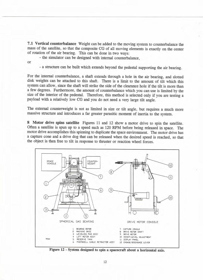
- a structure can be built which extends beyond the pedestal supporting the air bearing. For the intemal counterbalance, a shaft extends through a hole in the air bearing, and slotted disk weights can be attached to this shaft. There is a limit to the amount of tilt which this system can allow, since the shaft will strike the side of the clearance hole if the tilt is more than a few degrees. Furthermore, the amount of counterbalance which you can use is limited by the size of the interior of the pedestal. Therefore, this method is selected only if you are testing a payload with a relatively low CG and you do not need a very large tilt angle. The extemal counterweight is not as limited in size or tilt angle, but requires a much more massive stmcture and introduces a far greater parasitic moment of inertia to the system. 8 Motor drive spins satellite Figures 11 and 12 show a motor drive to spin the satellite. Often a satellite is spun up to a speed such as 120 RPM before being released in space. The motor drive accomplishes this spinning to duplicate the space environment. The motor drive has a capture cone and a drive dog that can be released when the desired speed is reached, so that the object is then free to tilt in response to thmster or reaction wheel forces.
SPACE V E H I C L E
: 4 )
S PHER ICAL GAS BEARING
1 BEARING ROTDR 2 MACHINE BASE 3 LEVELING PAD ASSY 4 L I FT MOTOR ASSY 5 RESERVE TANK 6 PHOTOCELL CABLE RETRACTOR ASSY
D R I V E MOTOR CONSOLE
7 CAPTURE CRADLE 8 DRIVE MOTOR SHAFT 9 DRIVE MOTOR 10 HEIGHT/LEVEL ADJUSTMENT 11 DISPLAY PANEL
12 ENGAGE/DISENGAGE LEVER
Figure 12 - System designed to spin a spacecraft about a horizontal axis.
12

9 Spinning about a horizontal axis There are instances where it is desirable to spin about a horizontal axis. Figure 12 shows a spherical air bearing system that accomplishes this. You can mount a spacecraft on one side and a counterbalance on the other, or in some instances it is possible to mount guidance components on one side and fuel tanks, etc. on the other. A hole through the shaft allows you to pass cables and hoses from one side to the other. In addition, this configuration permits 360"̂ rotation about both a vertical and horizontal axis with tilt about the vertical axis. 10 Measuring energy dissipation Although the major use for a "space simulator" is to test the attitude stability, dynamic response, and other characteristics of the flight control systems of satellites and reentry vehicles, there is another use for the air bearing platform: to determine the effect of energy dissipation on the motion of spinning spacecraft. If a solid object is made to spin in the weightless vacuum of space, then it will spin forever. However, a spacecraft contains items which are not solid and which introduce losses that cause the spacecraft to eventually stop spinning. These include fuel tanks, reaction wheels, nutation dampers, bolted structures which "creak", and possibly chemicals in liquid form. The illustration below shows a air bearing spin facility which was designed to measure these losses. To perform this test, the apparatus must be operated in a vacuum or in a helium tent (see SAWE paper number 2031 entitled "Measuring Small Losses in Rotating Assemblies").
KEYBOARD
Figure 13 - System for measuring energy dissipation of a spacecraft while spinning. This instrument can measure three quantities: (1) rotation speed, (2) dynamic balance, and (3) moment of inertia. The rotating assembly is first dynamically balanced using the built-in balancing feature. Then the MOI of the rotating assembly is measured. A tent surrounds the device. A built-in vacuum pump draws the fabric tightly around the rotor and payload, and helium is then introduced to fill the tent. The rotor is accelerated to the desired speed in the helimn environment and released. The computer monitors the speed vs. time. Since the
13
instrument can measure both moment of inertia and speed, the on-line computer can be programmed to determine the losses in the spinning payload, using the formula:
whQTt: T=friction torque, I=moment of inertia, and a=angular deceleration. i
Data can be measured in both helixmi and air, and the results in a vacuum can then be extrapolated. 11 Conclusions Although the spherical air bearing method of simulating weightlessness does not permit motion in all 6 degrees of freedom, it is the best solution for many applications. Complex systems using two or three air bearings can result in 6 degrees of freedom, but their cost is relatively high. Bearings are available to measure payloads weighing as much as 23,000 pounds. These systems are invaluable for testing the operation of attitude controls prior to launching an object into space.
ABOUT THE AUTHOR Richard Bovnton is President of Space Electronics, Inc., Berlin, Connecticut, a company he founded m 1959. Space Electronics, Inc. manufactures instruments to measure moment of inertia, center of gravity, and product of inertia. Mr. Boynton holds a B.E. degree in Electrical Engineering from Yale University and has completed graduate studies in Mechanical Engineering at Yale and M.I.T. He is the author of over 65 papers, includmg 29 papers presented at SAWE conferences. He was instrumental in creatmg the SAWE Recommended Practice for Standard Coordinate Systems for Reporting the Mass Properties of Flight Vehicles. Mr. Boynton has been a member of SAWE for 26 years and is currently Director of the Boston Chapter. In 1992 he was elected a Fellow of the SAWE. He has designed many of the mass properties measuring instruments manufactured by Space Electronics. Also, Mr. Boynton is the Chief Executive Officer of Mass Properties Engineering Corporation and is a professional foUcsinger.
14

Performing a load test on a 10,000 pound spherical air bearing. A load frame and concrete test weights are used to apply the load. ~ ^
Assembling a 20,000 pound capacity spherical air bearing. .
f Photo shows 3,500 pound test weights mounted on either side of air bearing ball. Retractable drive spins payload to desired speed. In actual use, one test weight is replaced by spacecraft.
Special machine designed to measure energy dissipation in spinning spacecraft.
15