user’s manual ver 1 - robotshop | robot store€¦ · 30 levels in position control mode, 16...
TRANSCRIPT
wCK series
User’s Manual
Intelligent Modular Robot
Ver 1.05
2/71
User’s Manual v1.0 wCK series
TABLE OF CONTENTS
1. INTRODUCTION p3 1-1 Introduction p3 1-2 Model Listing p4 1-3 Main Specifications p5 1-4 Main Features p5 1-5 Control Scheme p7 1-6 Application p8 1-7 Part List p10 1-8 Mechanical Specifications p10 1-9 Electrical & Control Specifications p12 2. USING wCK MODULE p13 2-1 Mechanical Connection p13 2-2 Electrical Connection p20 2-3 Communication p22 2-4 Software p25 3. CONTROL FUNCTIONS p26 3-1 Position Control p27 3-2 Synchronized Position Control p29 3-3 Passive Mode p30 3-4 Speed/Acceleration Setting p30 3-5 Movement Boundary Setting p30 3-6 Reverse-voltage Protection p30 3-7 Over-current Protection p30 3-8 Wheel Mode p30 3-9 Break Mode p30 3-10 External I/O Port p31 3-11 Self-running Motion p32 3-12 Initialization of wCK ID and Baud rate p33 A. APPENDIX p34 A-1 Communication Protocol p34 A-2 Communication Signal Adjustment Circuit Board p59 A-3 Baud rate Setting for Independent Controller p60 A-4 Application Example p63 A-5 Default Parameter Settings p70 A-6 Protocol Table p71

3/71
User’s Manual v1.0 wCK series
1 INTRODUCTION 1-1 Introduction RoboBuilder’s wCK module is an intelligent robotic module with which users can build creative robots of various shapes and easily operate and control robots. It is the first block type robotic module in the world that has joint insert assembly structure. This quick and simple joint assembly scheme enables users to simply plug a plastic joint part into wCK modules to complete linking two different wCK modules mechanically, which helps reduce building time dramatically. Internally a control board and a servo actuator mechanism are integrated together inside the small plastic enclosure. wCK module itself can operates as a small independent robot system because it is equipped with external I/O ports and can run a self-running motion program. wCK module adopted PID motion control technology and realized motion control characteristics as precise and accurate as industrial servo motors. Users can design and build robotic systems with multi-axis articulated mechanism much more easily and efficiently by adopting wCK robotic module. It’s because wCK module is designed for users to easily extend and do troubleshooting and maintenance.
[Figure 1-1a] Picture of wCK module(packaged)
[Figure 1-1b] Picture of wCK module

4/71
User’s Manual v1.0 wCK series
1-2 Model Listing The series name “wCK” comes from the sound “Wingchick” that the actuator module makes when in motion.
[Figure 1-2a] Model Name Scheme
[Figure 1-2b] Model Listings
5/71
User’s Manual v1.0 wCK series
1-3 Main Specifications Communication Multi drop Full Duplex UART serial communication Baud Rate 4,800bps ~ 921,600bps(8 levels) Extension Max 254 modules per channel(ID 0~253) Operating Voltage 6VDC ~ 10VDC(7.4VDC~8.4VDC recommended) Speed Max No Load Speed 0.15 sec/60 (̊wCK-1108 under recommended voltage) Stall Torque Max 13kg·cm(wCK-1413 under recommended voltage) Max Power 1.1W(wCK-1108, 1111), 1.4W(wCK-1413) Gear Ratio 1/173(wCK-1108), 1/241(wCK-1111, 1413) Control Mode Position Control, Speed Control, Torque Control Control Angle 0~254(Standard Resolution), 0~1,022(High Resolution) Operating Angle 0˚~269 (̊Standard Resolution), 0˚~333 (̊High Resolution) Resolution 8 bit/1.055 (̊Standard Rosolution), 10 bit/0.325 (̊High Resolution) Error Range ±0.8 (̊Standard Resolution) Speed Level 30 levels(Position Control Mode), 16 levels(Wheel Mode) Case Material Engineering Plastic Gear Material POM(wCK-1108), POM+Metal(wCK-1111,1413) Size 51.6 mm 27.1 mm 36.4 mm Weight 45g(wCK-1108), 49g(wCK-1111,1413)
1-4 Main Features All-in-One Integrated Robot Module
All components such as controller, sensor, actuator, I/O port are integrated in a small plastic enclosure.
Compact Design
Compact and fancy exterior design with smooth curved lines enhances its functionality as well as helps efficient mechanical system designing.
2 Way Mechanical Power Transmission
2 way mechanical power transmission structure enables users to build various structures of mechanical systems.
Quick & Simple Joint Assembly
Quick and simple joint assembly scheme enables users to simply plug a plastic joint into wCK modules to complete linking wCK modules, which helps invent creative robots and reduce building time dramatically. Presice PID Control
Position control error of ±0.8 ̊realized through precise PID control(in Standard Resolution) High resolution Mode 10 bit 1,024 steps(unit control angle 0.325 )̊, Standard Resolution Mode 8 bit 256steps(unit control angle 1.055 )̊
6/71
User’s Manual v1.0 wCK series
Error Compensation Algorithm
Special algorithm for position error compensation realized ±0.8 ̊level of error with low resolution potentiometer feedback. Position Control, Speed Control, Torque Control
Three different control modes help users apply wCK module to systems with various control requirements. Various Operation Mode
Position control mode, Synchronized position control mode, Wheel mode, Passive mode, Break mode, Self-running mode, etc Various Parameters
Various parameters configurable such as wCK ID, Baud rate, Position control resolution, PID gains, Movement speed, Acceleration range, Motion Boundary, Max operation current, etc Multi Drop Full Duplex UART serial communication
The Full Duplex UART two-way serial communication enables to connect to wCK directly without using separate communication device from external controller. Control Optimized Protocol
Minimized communication time delay by adopting optimized protocol structure and real-time response method for all commands.
External I/O Port
1channel A/D input(0V~5V), 2channels Digital Output(TTLlevel) Self-running Motion
wCK can run a motion and sensor interaction by itself without being controlled by external controller Various Speed Levels
30 levels in position control mode, 16 levels in 360 ̊wheel mode Voltage-adaptive Automatic Adjustment of Control Angle
wCK module can implement automatic compensation for control output according to real-time input voltage Windows based Programming Software
Windows-based software such as wCK programmer, Motion Builder, Action Builder Wide range of Input Voltage
Wide range of input voltage (6VDC~10VDC) Wide range of Control Angle

7/71
User’s Manual v1.0 wCK series
0˚~269 ̊in standard resolution, 0˚~333 ̊in high resolution Power-saving Break Mode
Break mode stops the motion of a wCK module and thus help hold still system’s mechanical structure without consuming electric power by using dynamic break effect. Passive Sensor Mode
In passive mode, wCK release torque and acts as a sensor Reverse-voltage Protection, Over-current Protection
Protection circuits built-in for reverse-voltage and over-current Initialization of ID and Baud Rate
wCK ID and baud rate can be initialized for debugging or troubleshooting purpose Two Metal Bearings for Mechanical Durability
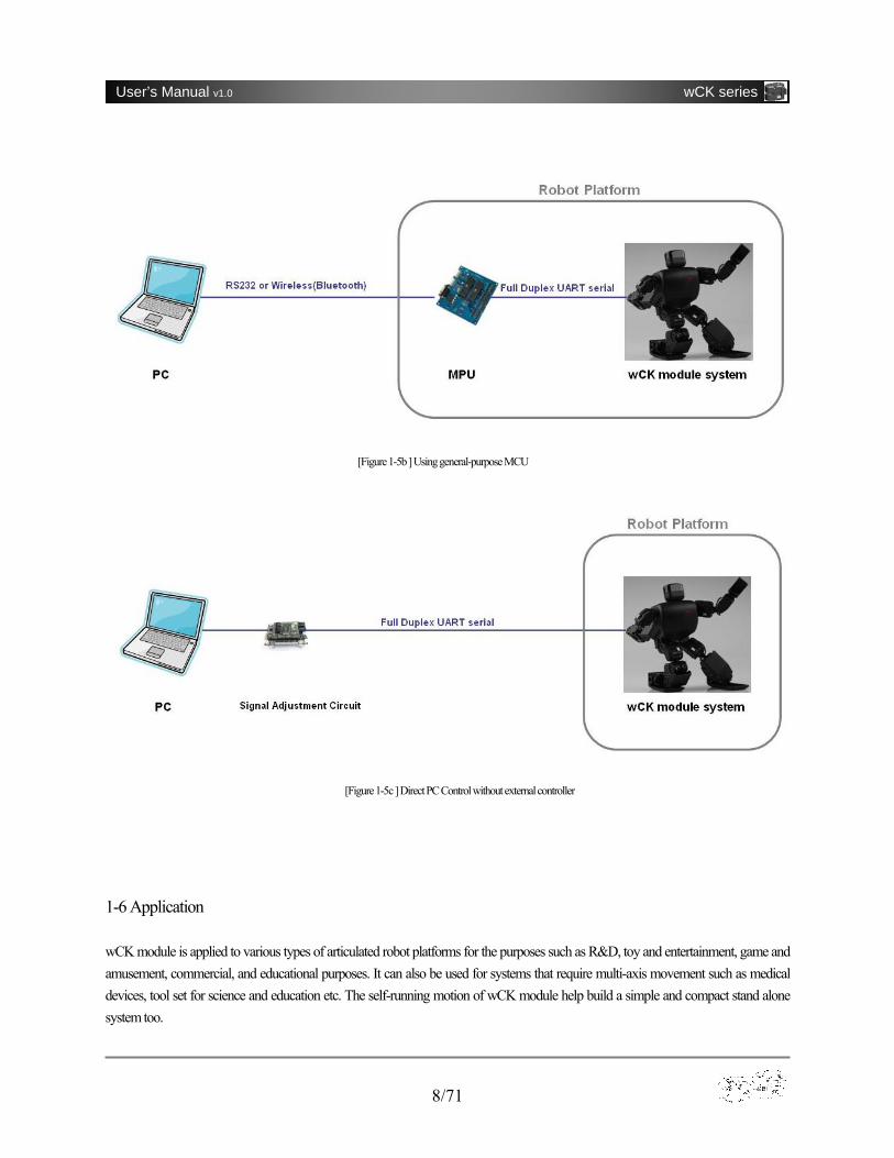
Mechanical durability is ensured with two metal bearings applied on rotation axis 1-5 Control Scheme wCK module can be controlled by RoboBuilder’s RBC controller, general puupose MCUs, as well as directly by a PC. In case of using RBC controller wCK module can be directly plugged onto the connectors of RBC controller because wCK module has signal adjusting circuit built-in and adjust signal levels between PC(RS-232 signal level) and wCK module(TTL signal level). A separate signal regulating circuit may be required when using a MCU or a PC to control wCK module. RoboBuilder provides separately this signal adjustment circuit board (refer to Appendix A-2 for detail). [Figure 1-5a ] Using RBC controller
8/71
User’s Manual v1.0 wCK series
1-6 Application wCK module is applied to various types of articulated robot platforms for the purposes such as R&D, toy and entertainment, game and amusement, commercial, and educational purposes. It can also be used for systems that require multi-axis movement such as medical devices, tool set for science and education etc. The self-running motion of wCK module help build a simple and compact stand alone system too.
[Figure 1-5b ] Using general-purpose MCU
[Figure 1-5c ] Direct PC Control without external controller

9/71
User’s Manual v1.0 wCK series
[Figure 1-6a] Application(Various Articulated Robots)

10/71
User’s Manual v1.0 wCK series
1-7 Part List Part List No Qty Part Name Use 도
1 1 EA wCK module Intelligent wCK robot module 2 1 EA Round Joint Transmit force of wCK module to external object 3 1 EA wCK Cable (4wire twisted) Wiring cable for wCK module 4 4 EA Bolt 1 (M2 40mm) Fix wCK module onto external object 5 4 EA Nut (M2) Fix wCK module onto external object 6 1 EA Bolt 2 (M2 8mm) Fix round joint to the axis of wCK module
[Figure 1-7a] Part List
11/71
User’s Manual v1.0 wCK series
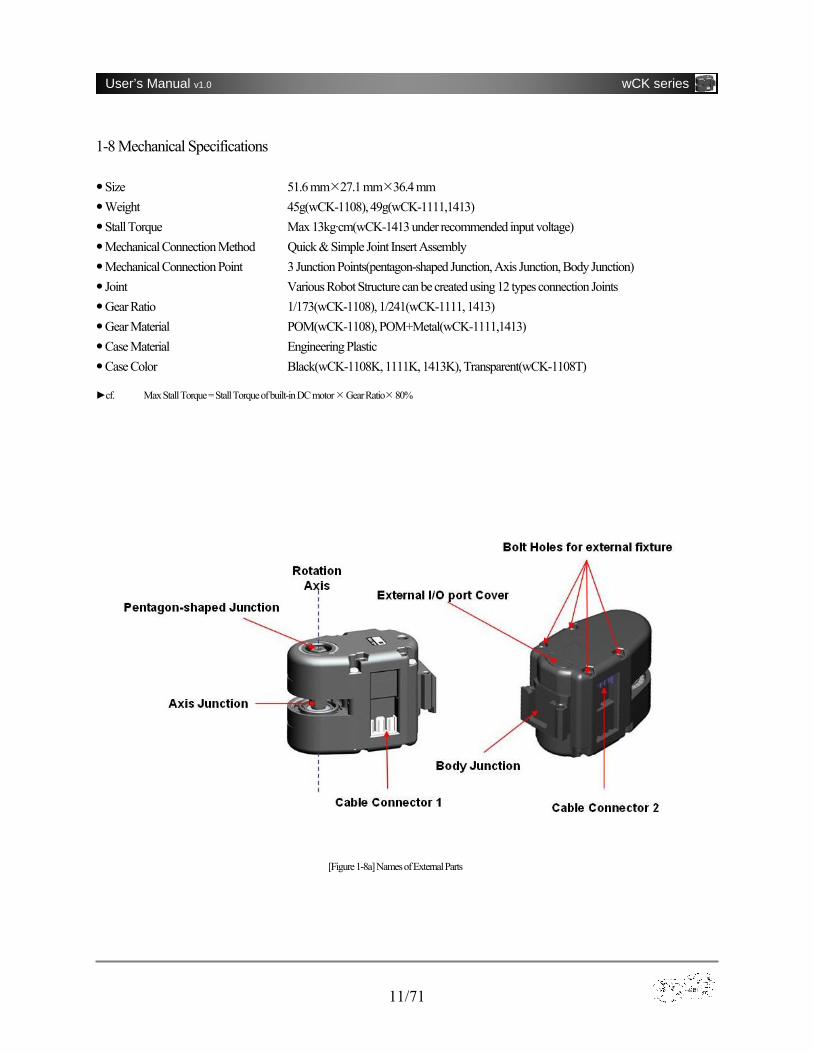
1-8 Mechanical Specifications Size 51.6 mm 27.1 mm 36.4 mm Weight 45g(wCK-1108), 49g(wCK-1111,1413) Stall Torque Max 13kg·cm(wCK-1413 under recommended input voltage) Mechanical Connection Method Quick & Simple Joint Insert Assembly Mechanical Connection Point 3 Junction Points(pentagon-shaped Junction, Axis Junction, Body Junction) Joint Various Robot Structure can be created using 12 types connection Joints Gear Ratio 1/173(wCK-1108), 1/241(wCK-1111, 1413) Gear Material POM(wCK-1108), POM+Metal(wCK-1111,1413) Case Material Engineering Plastic Case Color Black(wCK-1108K, 1111K, 1413K), Transparent(wCK-1108T)
►cf. Max Stall Torque = Stall Torque of built-in DC motor Gear Ratio 80%
[Figure 1-8a] Names of External Parts
12/71
User’s Manual v1.0 wCK series
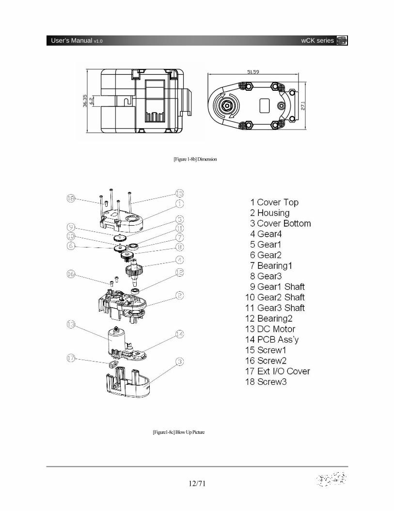
[Figure1-8c] Blow Up Picture
[Figure 1-8b] Dimension
13/71
User’s Manual v1.0 wCK series
1-9 Electrical & Control Specifications Communication Multi drop Full Duplex UART serial communication Baud Rate 4,800bps ~ 921,600bps(8 levels) Extension Max 254 modules per channel(ID 0~253) DC motor type Precious metal brush DC motor Operation Voltage 6VDC ~ 10VDC(7.4VDC~8.4VDC recommended) Max Current 400mA ~ 1,800mA (Over-current Protection) Reverse-voltage Protection 0 ~ -28V Max Power 1.4W(wCK-1413), 1.1W(wCK-1108, 1111) Speed Level 30 levels(Position Control Mode), 16 levels(Wheel Mode) Speed Max No Load Speed0.19sec/60 (̊wCK-1413), 0.21sec/60 (̊wCK-1111), 0.15sec/60 (̊wCK-1108) Acceleration Range range from 20 to 100 Max Stall Torque 13kg·cm(wCK-1413), 11kg·cm(wCK-1111), 8kg·cm(wCK-1108) under recommended input voltage Control Mode Position Control, Speed Control, Torque Control Control Angle 0~254(Standard Resolution), 0~1,022(High Resolution) Operation Angle 0˚~269 (̊Standard Resolution), 0˚~333 (̊High Resolution) Resolution 8 bit/1.055 (̊Standard Resolution), 10 bit/0.325 (̊High Resolution) Unit Control Angle 269 /̊255=1.055 ̊(Standard Resolution), 333 /̊1023=0.325 ̊(High Resolution) Control Error ±0.8 (̊8 bit Standard Resolution) P gain 1~120 recommended D gain 0~254 recommended I gain 0~10 recommended
►cf. Max Power = Max Power of built-in DC motor Gear Ratio 66%(the average efficiency of 4-step mechanical gear)
►cf. Max No Load Speed = Max No Load Speed of built-in DC motor 1 / Gear Ratio
2 USING wCK MODULE 2-1 Mechanical Connection wCK modules can be easily connected and extended by plugging various joint parts into the junction points of wCK module. This Quick & Simple assembly scheme enables users to design and build robot systems with various and complex articulated structure quickly and efficiently.

14/71
User’s Manual v1.0 wCK series
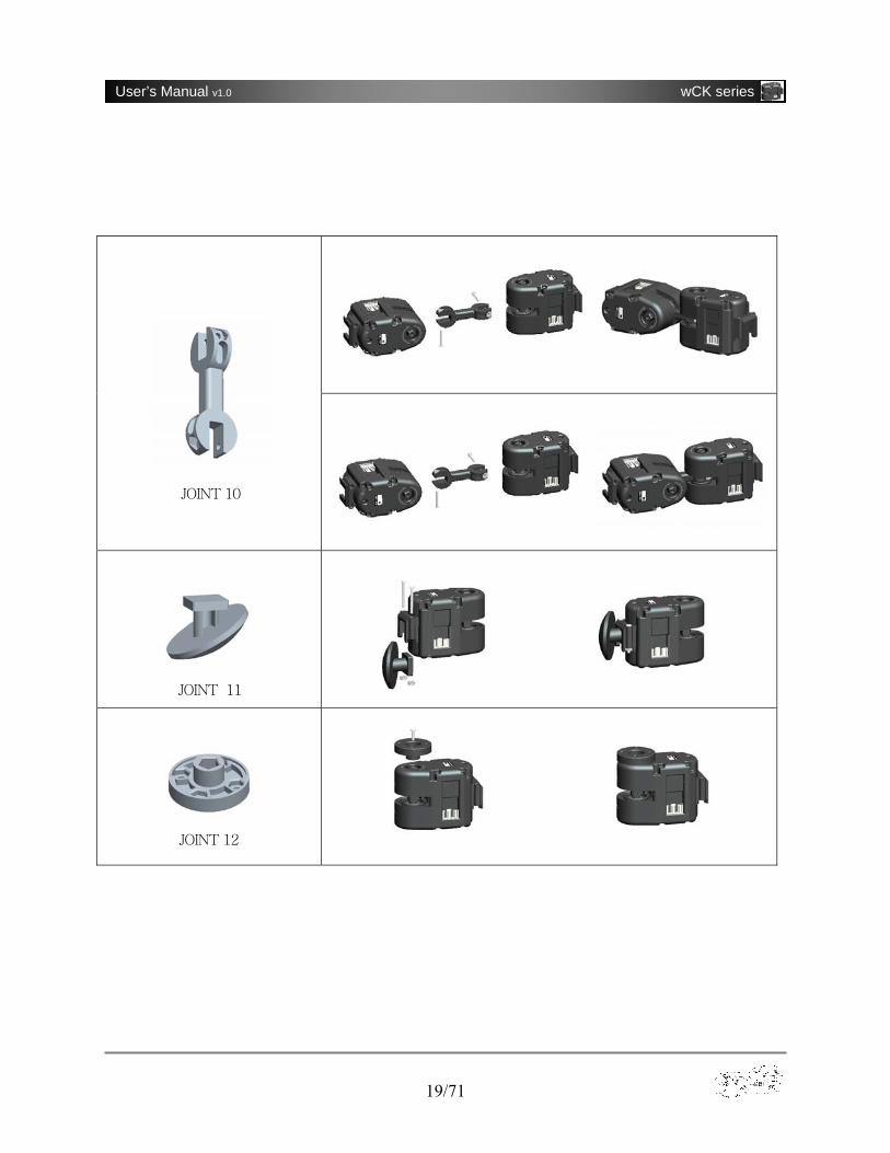
A variety of mechanical structures are available using the joints shown below in [Figure 2-1b]. When connecting a joint with wCK module the junction is held tight even without screwing bolts, which is very effective and helpful for users to invent creative structures in designing a new robotic system.
JOINT 1 JOINT 2 JOINT 3 JOINT 4 JOINT 5
JOINT 6 JOINT 7 JOINT 8 JOINT 9 JOINT 10
JOINT 11 JOINT 12
[Figure 2-1a] Joint Connection Scheme
[Figure 2-1b] Joint Type
(Joint sold separately as option)
15/71
User’s Manual v1.0 wCK series
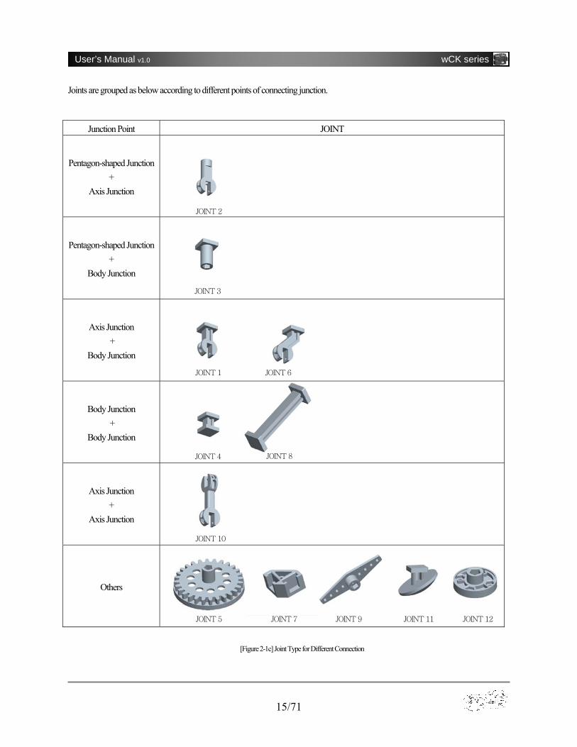
Joints are grouped as below according to different points of connecting junction.
Junction Point JOINT
Pentagon-shaped Junction +
Axis Junction
Pentagon-shaped Junction +
Body Junction
Axis Junction +
Body Junction
Body Junction +
Body Junction
Axis Junction +
Axis Junction
Others
[Figure 2-1c] Joint Type for Different Connection
JOINT 1
JOINT 2
JOINT 3
JOINT 4
JOINT 5 JOINT 7 JOINT 9
JOINT 10
JOINT 8
JOINT 6
JOINT 11 JOINT 12
16/71
User’s Manual v1.0 wCK series
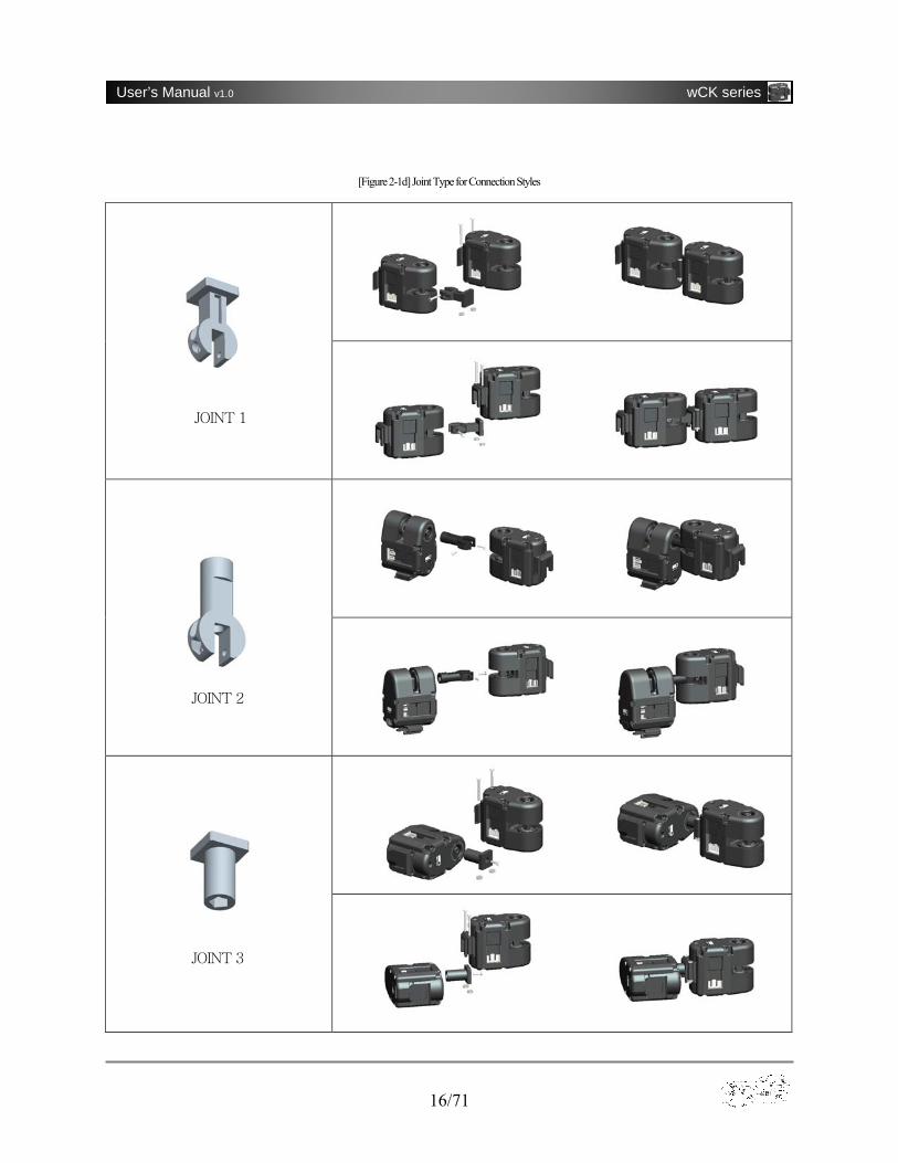
[Figure 2-1d] Joint Type for Connection Styles
JOINT 1
JOINT 2
JOINT 3
17/71
User’s Manual v1.0 wCK series
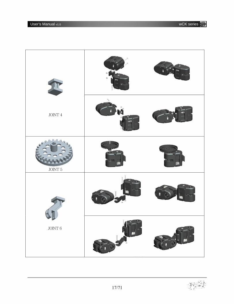
JOINT 4
JOINT 5
JOINT 6
18/71
User’s Manual v1.0 wCK series
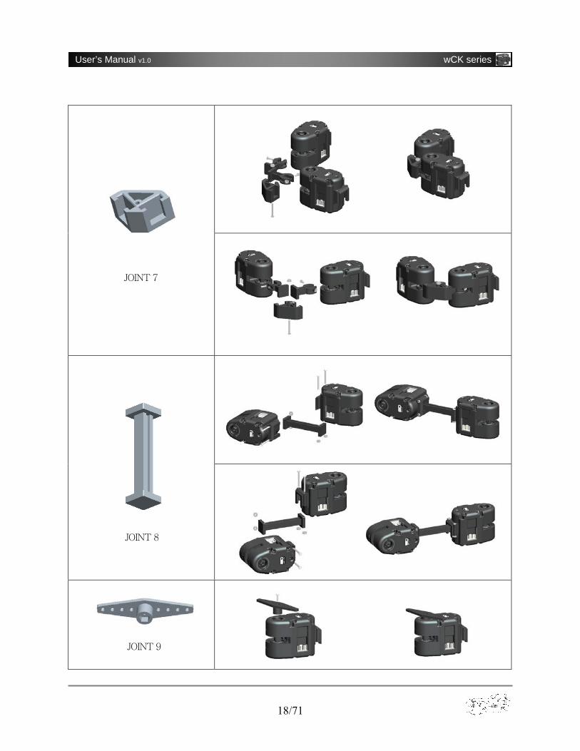
JOINT 7
JOINT 8
JOINT 9
19/71
User’s Manual v1.0 wCK series
JOINT 10
JOINT 12
JOINT 11
20/71
User’s Manual v1.0 wCK series
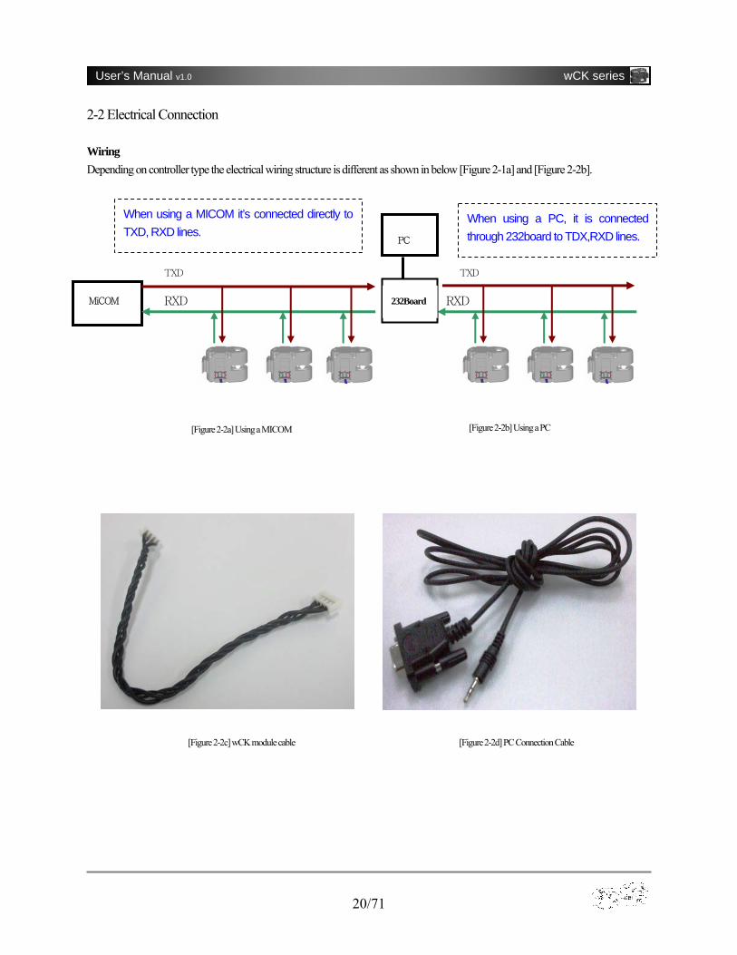
2-2 Electrical Connection Wiring Depending on controller type the electrical wiring structure is different as shown in below [Figure 2-1a] and [Figure 2-2b].
[Figure 2-2a] Using a MICOM [Figure 2-2b] Using a PC
[Figure 2-2d] PC Connection Cable [Figure 2-2c] wCK module cable
MiCOM
TXD
RXD
When using a MICOM it’s connected directly to TXD, RXD lines.
PC
TXD
RXD 232Board
When using a PC, it is connected through 232board to TDX,RXD lines.

21/71
User’s Manual v1.0 wCK series
Connectors wCK module has two built-in connectors on both sides of the body. The two connectors are electrically connected in parallel internally so the module is ready to communicate if either one of the two connectors are plugged. The other one is used to extend to another wCK module. The connectors at both ends of a wCK module cable are designed specially so that they can’t be plugged turned inside out, which eliminates the risk of making a wiring mistake.
[Figure 2-2e] wCK module Cable Connector & Pin Arrangement
22/71
User’s Manual v1.0 wCK series
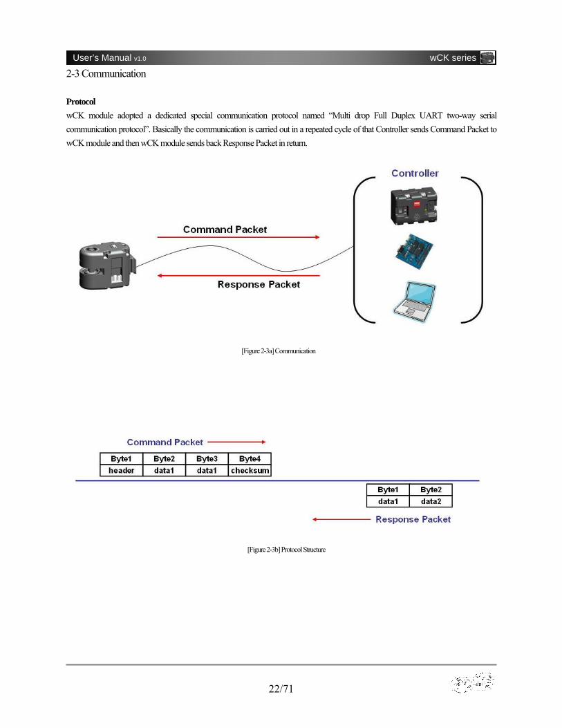
2-3 Communication Protocol wCK module adopted a dedicated special communication protocol named “Multi drop Full Duplex UART two-way serial communication protocol”. Basically the communication is carried out in a repeated cycle of that Controller sends Command Packet to wCK module and then wCK module sends back Response Packet in return.
[Figure 2-3a] Communication
[Figure 2-3b] Protocol Structure
23/71
User’s Manual v1.0 wCK series
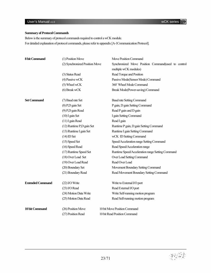
Summary of Protocol Commands Below is the summary of protocol commands required to control a wCK module. For detailed explanation of protocol commands, please refer to appendix [A-1Communication Protocol]. 8 bit Command (1) Position Move Move Position Command
(2) Synchronized Position Move Synchronized Move Position Command(used to control multiple wCK modules)
(3) Status Read Read Torque and Position (4) Passive wCK Passive Mode(Sensor Mode) Command (5) Wheel wCK 360 ̊Wheel Mode Command (6) Break wCK Break Mode(Power-saving) Command
Set Command (7) Baud rate Set Baud rate Setting Command
(8) P,D gain Set P gain, D gain Setting Command (9) P,D gain Read Read P gain and D gain (10) I gain Set I gain Setting Command (11) I gain Read Read I gain (12) Runtime P,D gain Set Runtime P gain, D gain Setting Command (13) Runtime I gain Set Runtime I gain Setting Command (14) ID Set wCK ID Setting Command (15) Speed Set Speed/Acceleration range Setting Command (16) Speed Read Read Speed/Acceleration range (17) Runtime Speed Set Runtime Speed/Acceleration range Setting Command (18) Over Load Set Over Load Setting Command (19) Over Load Read Read Over Load (20) Boundary Set Movement Boundary Setting Command (21) Boundary Read Read Movement Boundary Setting Command
Extended Command (22) I/O Write Write to External I/O port
(23) I/O Read Read External I/O port (24) Motion Data Write Write Self-running motion program (25) Motion Data Read Read Self-running motion program
10 bit Command (26) Position Move 10 bit Move Position Command
(27) Position Read 10 bit Read Position Command
24/71
User’s Manual v1.0 wCK series
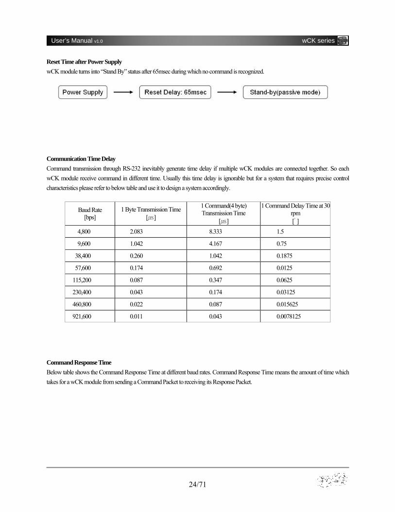
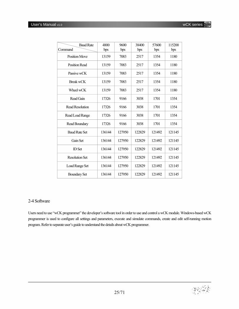
Reset Time after Power Supply wCK module turns into “Stand By” status after 65msec during which no command is recognized. Communication Time Delay Command transmission through RS-232 inevitably generate time delay if multiple wCK modules are connected together. So each wCK module receive command in different time. Usually this time delay is ignorable but for a system that requires precise control characteristics please refer to below table and use it to design a system accordingly. Command Response Time Below table shows the Command Response Time at different baud rates. Command Response Time means the amount of time which takes for a wCK module from sending a Command Packet to receiving its Response Packet.
Baud Rate [bps]
1 Byte Transmission Time [㎲]
1 Command(4 byte) Transmission Time
[㎲]
1 Command Delay Time at 30 rpm [゚ ]
4,800 2.083 8.333 1.5
9,600 1.042 4.167 0.75
38,400 0.260 1.042 0.1875
57,600 0.174 0.692 0.0125
115,200 0.087 0.347 0.0625
230,400 0.043 0.174 0.03125
460,800 0.022 0.087 0.015625
921,600 0.011 0.043 0.0078125
25/71
User’s Manual v1.0 wCK series
2-4 Software Users need to use “wCK programmer” the developer’s software tool in order to use and control a wCK module. Windows-based wCK programmer is used to configure all settings and parameters, execute and simulate commands, create and edit self-running motion program. Refer to separate user’s guide to understand the details about wCK programmer.
Baud Rate Command
4800bps
9600bps
38400bps
57600bps
115200 bps
Position Move 13159 7083 2517 1354 1180
Position Read 13159 7083 2517 1354 1180
Passive wCK 13159 7083 2517 1354 1180
Break wCK 13159 7083 2517 1354 1180
Wheel wCK 13159 7083 2517 1354 1180
Read Gain 17326 9166 3038 1701 1354
Read Resolution 17326 9166 3038 1701 1354
Read Load Range 17326 9166 3038 1701 1354
Read Boundary 17326 9166 3038 1701 1354
Baud Rate Set 136144 127950 122829 121492 121145
Gain Set 136144 127950 122829 121492 121145
ID Set 136144 127950 122829 121492 121145
Resolution Set 136144 127950 122829 121492 121145
Load Range Set 136144 127950 122829 121492 121145
Boundary Set 136144 127950 122829 121492 121145

26/71
User’s Manual v1.0 wCK series
[Figure 2-4a] wCK Programmer Screen Layout
[Figure 2-4b] Setting & Programming Area
27/71
User’s Manual v1.0 wCK series
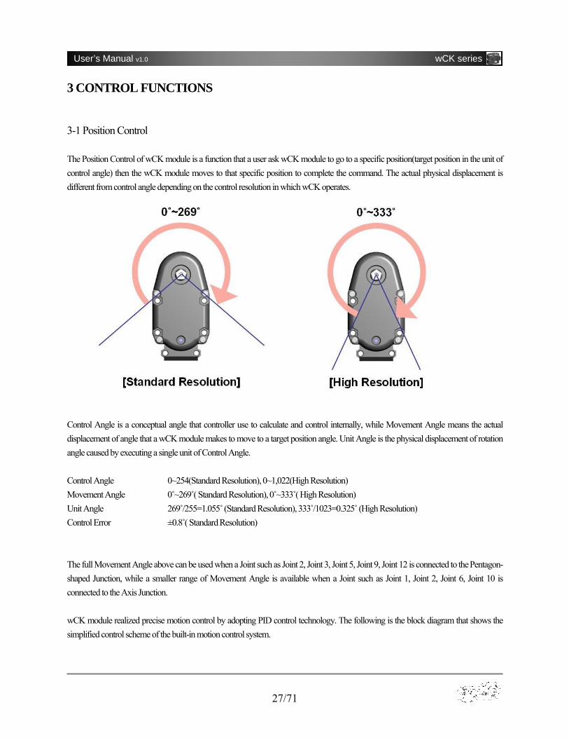
3 CONTROL FUNCTIONS 3-1 Position Control The Position Control of wCK module is a function that a user ask wCK module to go to a specific position(target position in the unit of control angle) then the wCK module moves to that specific position to complete the command. The actual physical displacement is different from control angle depending on the control resolution in which wCK operates. Control Angle is a conceptual angle that controller use to calculate and control internally, while Movement Angle means the actual displacement of angle that a wCK module makes to move to a target position angle. Unit Angle is the physical displacement of rotation angle caused by executing a single unit of Control Angle. Control Angle 0~254(Standard Resolution), 0~1,022(High Resolution) Movement Angle 0˚~269 (̊ Standard Resolution), 0˚~333 (̊ High Resolution) Unit Angle 269 /̊255=1.055 ̊(Standard Resolution), 333 /̊1023=0.325 ̊(High Resolution) Control Error ±0.8 (̊ Standard Resolution) The full Movement Angle above can be used when a Joint such as Joint 2, Joint 3, Joint 5, Joint 9, Joint 12 is connected to the Pentagon-shaped Junction, while a smaller range of Movement Angle is available when a Joint such as Joint 1, Joint 2, Joint 6, Joint 10 is connected to the Axis Junction. wCK module realized precise motion control by adopting PID control technology. The following is the block diagram that shows the simplified control scheme of the built-in motion control system.

28/71
User’s Manual v1.0 wCK series
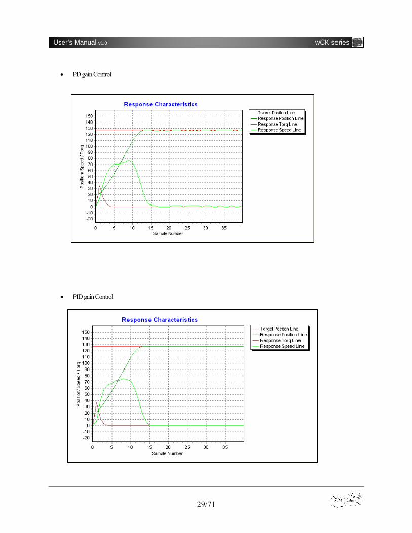
Below are the response characteristics graphs that show the different response characteristics of wCK module when each method of P gain Control, PD gain Control, and PID gain Control is applied.
• P gain Control
29/71
User’s Manual v1.0 wCK series
• PD gain Control
• PID gain Control
30/71
User’s Manual v1.0 wCK series
3-2 Synchronized Position Control Synchronized Position Control function is used to synchronize and control multiple wCK modules that are connected electrically on a same channel. Maximum 31 wCK modules can be connected and controlled simultaneously so this function is very useful in motion controlling a multi-axis robotic systems. 3-3 Passive Mode Passive wCK Mode is used to release the torque out of the axis of the wCK module and so that the rotation axis is moved smoothly by external force, which means wCK module play the role of a sensor. 3-4 Speed/Acceleration Setting User can select and change the levels of speed(from 0 to 30) and acceleration range(from 20 to 100) of a wCK module. 3-5 Movement Boundary Setting User can set the movement boundary range of a wCK so that wCK can move only within the specified range of rotation angle. This function is useful for applications that requires a motion in a narrow range of movement angle is critical. 3-6 Reverse-voltage Protection wCK module has reverse-voltage protection circuit built-in inside to protect from user’s wiring mistake. 3-7 Over-current Protection wCK module has over-current(over-torque) protection circuit built-in inside to protect product from excessive external force and protect user from injury. A range of from 33 to 199 is selectable for actual scale of current from 400 mA to 1,800 mA. 3-8 Wheel Mode Using wCK module’s 360 ̊Wheel Mode a user can build a system that requires a spinning motion at a specified rotation speed. Spinning in either clock-wise direction and counter clock-wise direction is selectable and 16 levels of speed can be set up. 3-9 Break Mode

31/71
User’s Manual v1.0 wCK series
Break Mode stops the motion of a wCK module and thus help hold still a system’s mechanical structure without consuming electric power by using dynamic break effect. Once break mode applied, all wCK modules connected on a single channel turn into Break Mode. 3-10 External I/O Port wCK module has 1 channel of A/D input(0V~5V) and 2 channels of Digital Output(TTL level).
[Figure 3-10] External I/O Port & Pin Arrangement
32/71
User’s Manual v1.0 wCK series
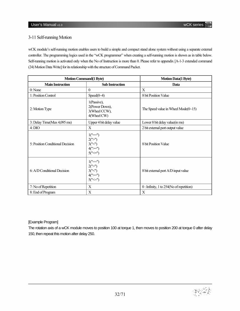
3-11 Self-running Motion wCK module’s self-running motion enables users to build a simple and compact stand alone system without using a separate external controller. The programming logics used in the “wCK programmer” when creating a self-running motion is shown as in table below. Self-running motion is activated only when the No of Instruction is more than 0. Please refer to appendix [A-1-3 extended command (24) Motion Data Write] for its relationship with the structure of Command Packet.
Motion Command(1 Byte) Motion Data(1 Byte) Main Instruction Sub Instruction Data
0: None 0 X 1: Position Control Speed(0~4) 8 bit Position Value
2: Motion Type
1(Passive), 2(Power Down), 3(Wheel CCW), 4(Wheel CW)
The Speed value in Wheel Mode(0~15)
3: Delay Time(Max 4,095 ms) Upper 4 bit delay value Lower 8 bit delay value(in ms) 4: DIO X 2 bit external port output value
5: Position Conditional Decision
1("==") 2(">") 3("<") 4(">=") 5("<=")
8 bit Position Value
6: A/D Conditional Decision
1("==") 2(">") 3("<") 4(">=") 5("<=")
8 bit external port A/D input value
7: No of Repetition X 0 : Infinity, 1 to 254(No of repetition) 8: End of Program X X
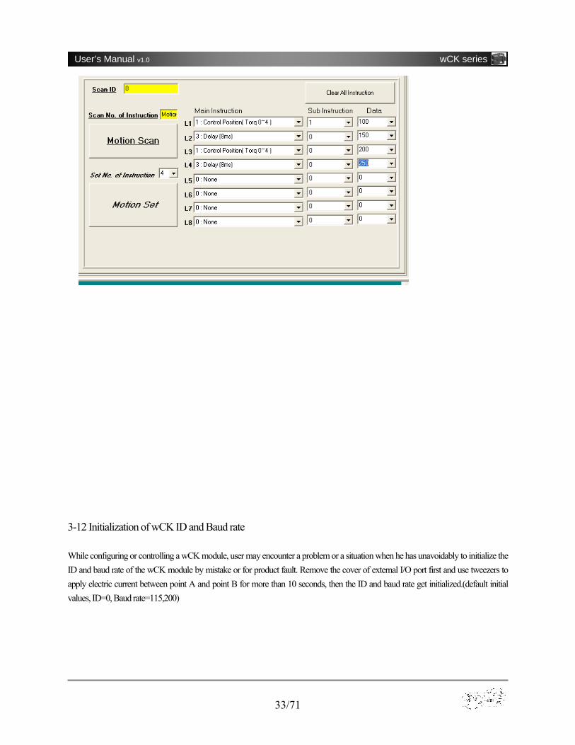
[Example Program] The rotation axis of a wCK module moves to position 100 at torque 1, then moves to position 200 at torque 0 after delay 150, then repeat this motion after delay 250.
33/71
User’s Manual v1.0 wCK series
3-12 Initialization of wCK ID and Baud rate While configuring or controlling a wCK module, user may encounter a problem or a situation when he has unavoidably to initialize the ID and baud rate of the wCK module by mistake or for product fault. Remove the cover of external I/O port first and use tweezers to apply electric current between point A and point B for more than 10 seconds, then the ID and baud rate get initialized.(default initial values, ID=0, Baud rate=115,200)

34/71
User’s Manual v1.0 wCK series
A. APPENDIX A-1 Communication Protocol A-1-1 8 bit Command
(1) Position Move
“Position Move” command makes wCK module return the values of current load and current position to controller and then move to a
specified target position.
▶Command Packet
Header = 0xFF
Data1
Torque ID 7 6 5 4 3 2 1 0
Torq : 0(※ Max)~4(Min), ID : 0~30
Target position = 0~254
Checksum = (Data1 X OR Target position) AND 0x7F
▶Response Packet
※Load : 0~254, Position : 0~254
e.g.) Command a wCK module with ID 0 to move to target position 0x7F(127) at torque 0
Command Packet
1byte 1byte 1byte 1byte
0xFF 0x00 0x7F 0x7F
Response Packet
1byte 1byte
Load Position
1byte 1byte 1byte 1byte
Header Data1 Target position Checksum
1byte 1byte
Load Position
35/71
User’s Manual v1.0 wCK series
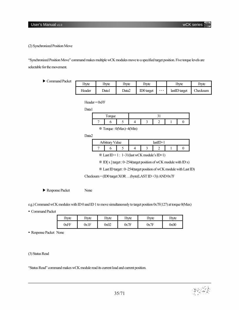
(2) Synchronized Position Move
“Synchronized Position Move” command makes multiple wCK modules move to a specified target position. Five torque levels are
selectable for the movement.
▶Command Packet
Header = 0xFF
Data1
Torque 31 7 6 5 4 3 2 1 0
※Torque : 0(Max)~4(Min)
Data2
Arbitrary Value lastID+1 7 6 5 4 3 2 1 0
※Last ID + 1 : 1~31(last wCK module’s ID+1)
※ ID[ x ] target : 0~254(target position of wCK module with ID x)
Last ID target ※ : 0~254(target position of wCK module with Last ID)
Checksum = (ID0 target XOR …(byte(LAST ID +3)) AND 0x7F
▶Response Packet None
e.g.) Command wCK modules with ID 0 and ID 1 to move simultaneously to target position 0x7F(127) at torque 0(Max)
Command Packet
1byte 1byte 1byte 1byte 1byte 1byte
0xFF 0x1F 0x02 0x7F 0x7F 0x00
Response Packet None
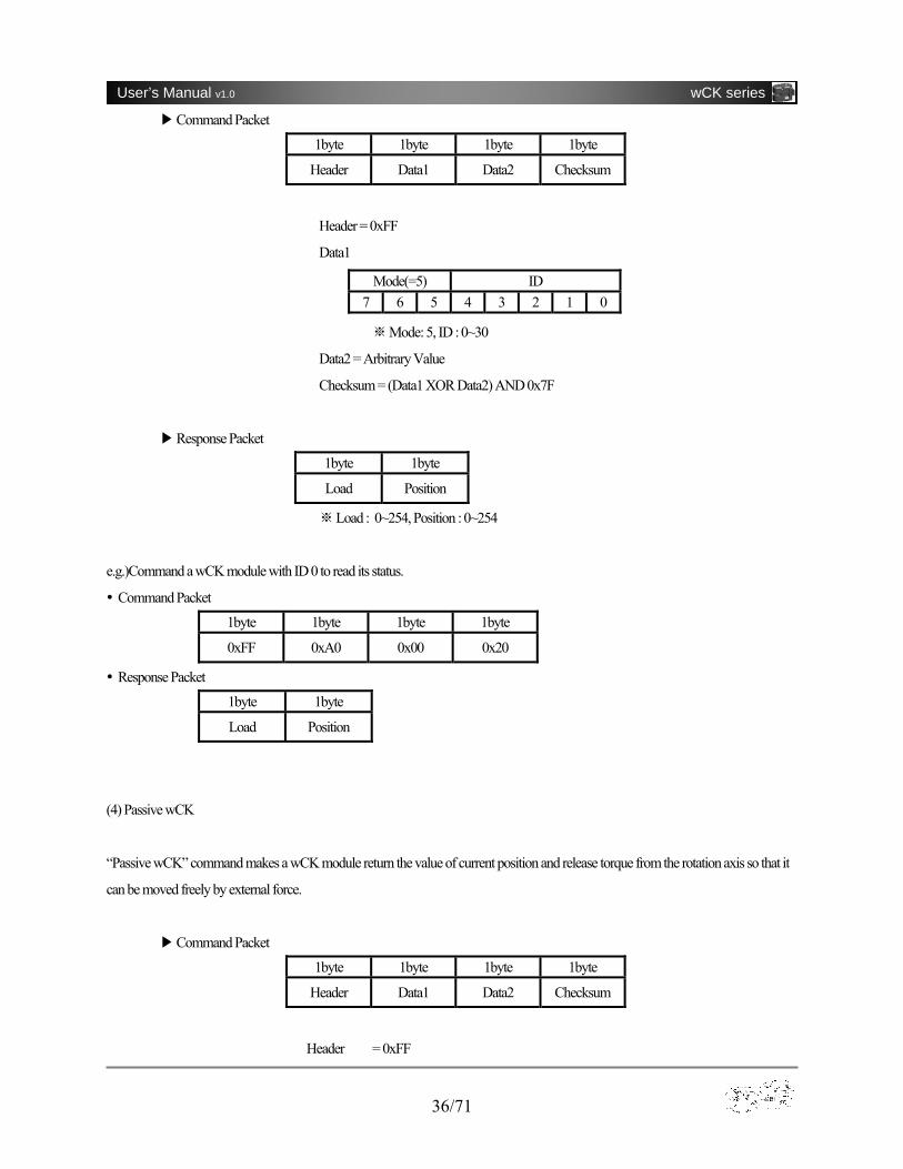
(3) Status Read
“Status Read” command makes wCK module read its current load and current position.
1byte 1byte 1byte 1byte 1byte 1byte
Header Data1 Data2 ID0 target ・・・ lastID target Checksum
36/71
User’s Manual v1.0 wCK series
▶Command Packet
1byte 1byte 1byte 1byte
Header Data1 Data2 Checksum
Header = 0xFF
Data1
※Mode: 5, ID : 0~30
Data2 = Arbitrary Value
Checksum = (Data1 XOR Data2) AND 0x7F
▶Response Packet
1byte 1byte
Load Position
※Load : 0~254, Position : 0~254
e.g.)Command a wCK module with ID 0 to read its status.
Command Packet
1byte 1byte 1byte 1byte
0xFF 0xA0 0x00 0x20
Response Packet
1byte 1byte
Load Position
(4) Passive wCK
“Passive wCK” command makes a wCK module return the value of current position and release torque from the rotation axis so that it
can be moved freely by external force.
▶Command Packet
1byte 1byte 1byte 1byte
Header Data1 Data2 Checksum
Header = 0xFF
Mode(=5) ID 7 6 5 4 3 2 1 0

37/71
User’s Manual v1.0 wCK series
Data1
Mode(=6) ID 7 6 5 4 3 2 1 0
※Mode : 6, ID : 0~30
Data2
Mode(=1) Arbitrary Value 7 6 5 4 3 2 1 0
Mode ※ : 1
Checksum = (Data1 XOR Data2) AND 0x7F
▶Response Packet
1byte 1byte
Data2 Position
※Position : 0~254
e.g.)Command a wCK module with ID 0 to turn into Passive wCK mode
Command Packet
1byte 1byte 1byte 1byte
0xFF 0xC0 0x10 0x50
Response Packet
1byte 1byte
0x10 Position
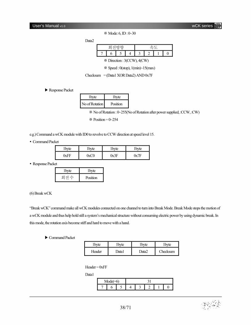
(5) Wheel wCK
“Wheel wCK” command makes a wCK module carry out 360 ゚revolving motion. 16 different speed levels are selectable.
▶Command Packet
1byte 1byte 1byte 1byte
Header Data1 Data2 Checksum
Header = 0xFF
Data1
Mode(=6) ID 7 6 5 4 3 2 1 0
38/71
User’s Manual v1.0 wCK series
※Mode: 6, ID : 0~30
Data2
회전방향 속도 7 6 5 4 3 2 1 0
※Direction : 3(CCW), 4(CW)
※Speed : 0(stop), 1(min)~15(max)
Checksum = (Data1 XOR Data2) AND 0x7F
▶Response Packet
1byte 1byte
No of Rotation Position
※No of Rotation : 0~255(No of Rotation after power supplied, :CCW, :CW)
※Position = 0~254
e.g.) Command a wCK module with ID0 to revolve to CCW direction at speed level 15.
Command Packet
1byte 1byte 1byte 1byte
0xFF 0xC0 0x3F 0x7F
Response Packet
1byte 1byte
회전 수 Position
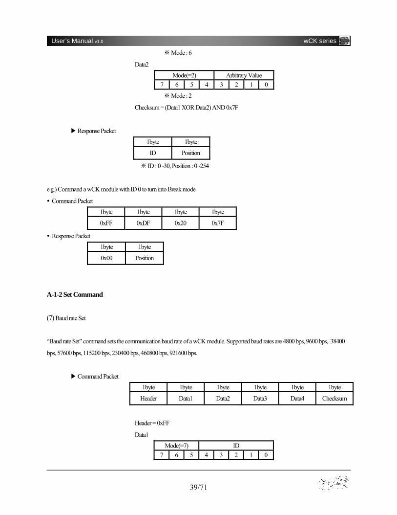
(6) Break wCK
“Break wCK” command make all wCK modules connected on one channel to turn into Break Mode. Break Mode stops the motion of
a wCK module and thus help hold still a system’s mechanical structure without consuming electric power by using dynamic break. In
this mode, the rotation axis become stiff and hard to move with a hand.
▶Command Packet
1byte 1byte 1byte 1byte
Header Data1 Data2 Checksum
Header = 0xFF
Data1
Mode(=6) 31 7 6 5 4 3 2 1 0
39/71
User’s Manual v1.0 wCK series
Mode : 6 ※
Data2
Mode(=2) Arbitrary Value 7 6 5 4 3 2 1 0
Mode : 2※
Checksum = (Data1 XOR Data2) AND 0x7F
▶Response Packet
1byte 1byte
ID Position
ID : 0~30, ※ Position : 0~254
e.g.) Command a wCK module with ID 0 to turn into Break mode
Command Packet
1byte 1byte 1byte 1byte
0xFF 0xDF 0x20 0x7F
Response Packet
1byte 1byte
0x00 Position
A-1-2 Set Command (7) Baud rate Set
“Baud rate Set” command sets the communication baud rate of a wCK module. Supported baud rates are 4800 bps, 9600 bps, 38400
bps, 57600 bps, 115200 bps, 230400 bps, 460800 bps, 921600 bps.
▶Command Packet
1byte 1byte 1byte 1byte 1byte 1byte
Header Data1 Data2 Data3 Data4 Checksum
Header = 0xFF
Data1
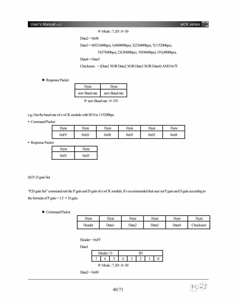
Mode(=7) ID 7 6 5 4 3 2 1 0
40/71
User’s Manual v1.0 wCK series
※Mode : 7, ID : 0~30
Data2 = 0x08
Data3 = 0(921600bps), 1(460800bps), 3(230400bps), 7(115200bps),
15(57600bps), 23(38400bps), 95(9600bps), 191(4800bps),
Data4 = Data3
Checksum = (Data1 XOR Data2 XOR Data3 XOR Data4) AND 0x7F
▶Response Packet
1byte 1byte
new Baud rate new Baud rate
※ new Baud rate : 0~191
e.g.) Set the baud rate of a wCK module with ID 0 to 115200bps.
Command Packet
1byte 1byte 1byte 1byte 1byte 1byte
0xFF 0xE0 0x08 0x03 0x03 0x68
Response Packet
1byte 1byte
0x03 0x03
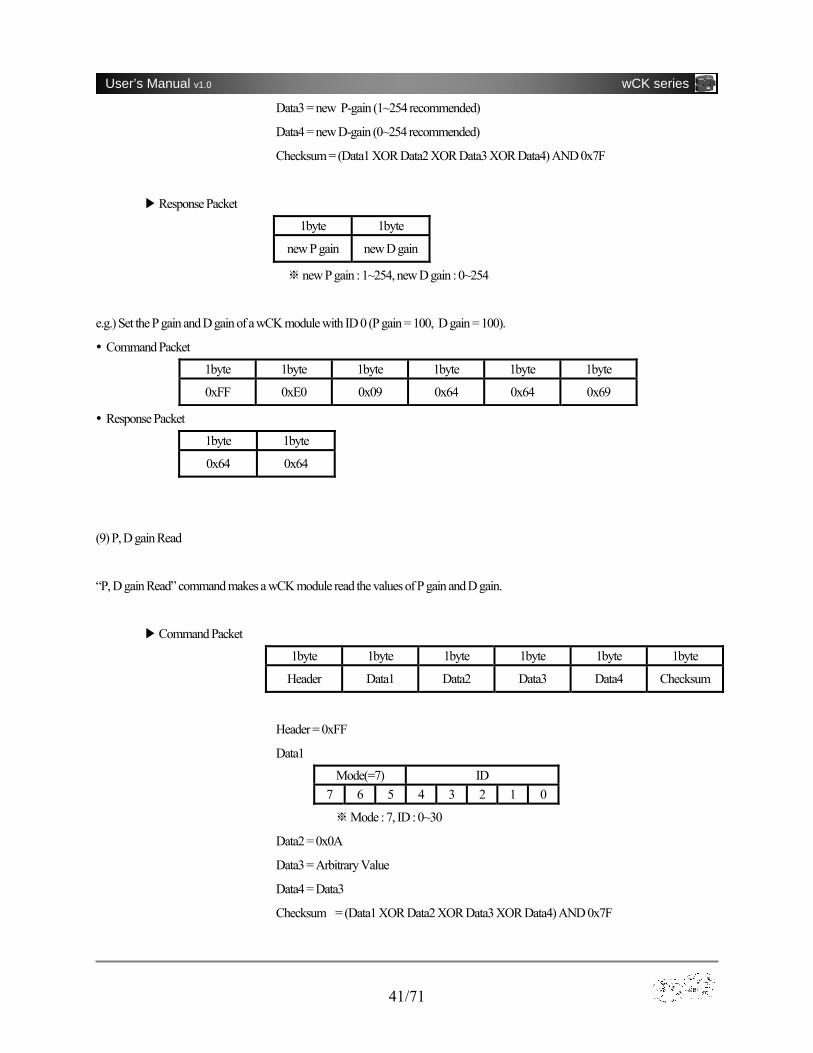
(8) P, D gain Set
“P,D gain Set” command sets the P gain and D gain of a wCK module. It’s recommended that user set P gain and D gain according to
the formula of P gain = 1.5 D gain.
▶Command Packet
1byte 1byte 1byte 1byte 1byte 1byte
Header Data1 Data2 Data3 Data4 Checksum
Header = 0xFF
Data1
Mode(=7) ID 7 6 5 4 3 2 1 0
※Mode : 7, ID : 0~30
Data2 = 0x09
41/71
User’s Manual v1.0 wCK series
Data3 = new P-gain (1~254 recommended)
Data4 = new D-gain (0~254 recommended)
Checksum = (Data1 XOR Data2 XOR Data3 XOR Data4) AND 0x7F
▶Response Packet
1byte 1byte
new P gain new D gain
new※ P gain : 1~254, new D gain : 0~254
e.g.) Set the P gain and D gain of a wCK module with ID 0 (P gain = 100, D gain = 100).
Command Packet
1byte 1byte 1byte 1byte 1byte 1byte
0xFF 0xE0 0x09 0x64 0x64 0x69
Response Packet
1byte 1byte
0x64 0x64
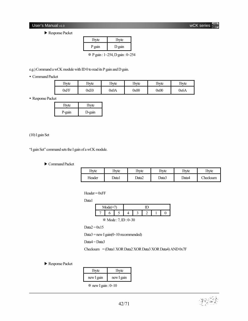
(9) P, D gain Read
“P, D gain Read” command makes a wCK module read the values of P gain and D gain.
▶Command Packet
1byte 1byte 1byte 1byte 1byte 1byte
Header Data1 Data2 Data3 Data4 Checksum
Header = 0xFF
Data1
Mode(=7) ID 7 6 5 4 3 2 1 0
Mode : 7, ID : 0~30※
Data2 = 0x0A
Data3 = Arbitrary Value
Data4 = Data3
Checksum = (Data1 XOR Data2 XOR Data3 XOR Data4) AND 0x7F
42/71
User’s Manual v1.0 wCK series
▶Response Packet
1byte 1byte
P gain D gain
P gain : 1~254, D gain : 0~254※
e.g.) Command a wCK module with ID 0 to read its P gain and D gain.
Command Packet
1byte 1byte 1byte 1byte 1byte 1byte
0xFF 0xE0 0x0A 0x00 0x00 0x6A
Response Packet
1byte 1byte
P-gain D-gain
(10) I gain Set
“I gain Set” command sets the I gain of a wCK module.
▶Command Packet
1byte 1byte 1byte 1byte 1byte 1byte
Header Data1 Data2 Data3 Data4 Checksum
Header = 0xFF
Data1
Mode(=7) ID 7 6 5 4 3 2 1 0
Mode : 7, I※ D : 0~30
Data2 = 0x15
Data3 = new I gain(0~10 recommended)
Data4 = Data3
Checksum = (Data1 XOR Data2 XOR Data3 XOR Data4) AND 0x7F
▶Response Packet
1byte 1byte
new I gain new I gain
new※ I gain : 0~10
43/71
User’s Manual v1.0 wCK series
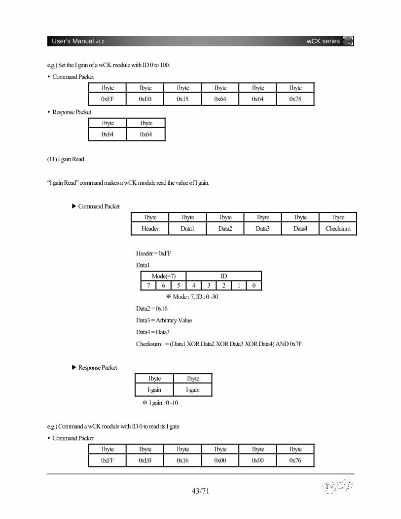
e.g.) Set the I gain of a wCK module with ID 0 to 100.
Command Packet
1byte 1byte 1byte 1byte 1byte 1byte
0xFF 0xE0 0x15 0x64 0x64 0x75
Response Packet
1byte 1byte
0x64 0x64
(11) I gain Read
“I gain Read” command makes a wCK module read the value of I gain.
▶Command Packet
1byte 1byte 1byte 1byte 1byte 1byte
Header Data1 Data2 Data3 Data4 Checksum
Header = 0xFF
Data1
Mode(=7) ID 7 6 5 4 3 2 1 0
Mode : 7, ID : 0~30※
Data2 = 0x16
Data3 = Arbitrary Value
Data4 = Data3
Checksum = (Data1 XOR Data2 XOR Data3 XOR Data4) AND 0x7F
▶Response Packet
1byte 1byte
I-gain I-gain
I ※ gain : 0~10
e.g.) Command a wCK module with ID 0 to read its I gain
Command Packet
1byte 1byte 1byte 1byte 1byte 1byte
0xFF 0xE0 0x16 0x00 0x00 0x76
44/71
User’s Manual v1.0 wCK series
Response Packet
1byte 1byte
I-gain I-gain
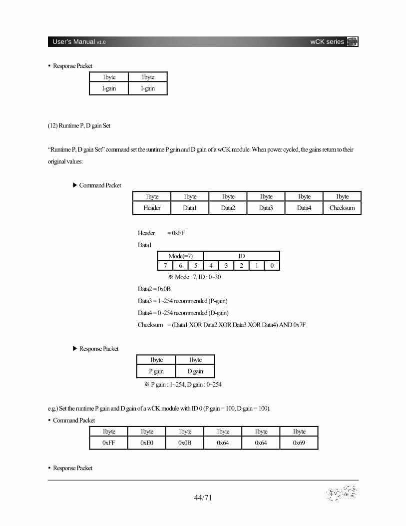
(12) Runtime P, D gain Set
“Runtime P, D gain Set” command set the runtime P gain and D gain of a wCK module. When power cycled, the gains return to their
original values.
▶Command Packet
1byte 1byte 1byte 1byte 1byte 1byte
Header Data1 Data2 Data3 Data4 Checksum
Header = 0xFF
Data1
Mode(=7) ID 7 6 5 4 3 2 1 0
Mode : 7, ID : 0~30※
Data2 = 0x0B
Data3 = 1~254 recommended (P-gain)
Data4 = 0~254 recommended (D-gain)
Checksum = (Data1 XOR Data2 XOR Data3 XOR Data4) AND 0x7F
▶Response Packet
1byte 1byte
P gain D gain
※ P gain : 1~254, D gain : 0~254
e.g.) Set the runtime P gain and D gain of a wCK module with ID 0 (P gain = 100, D gain = 100).
Command Packet
1byte 1byte 1byte 1byte 1byte 1byte
0xFF 0xE0 0x0B 0x64 0x64 0x69
Response Packet

45/71
User’s Manual v1.0 wCK series
1byte 1byte
0x64 0x64
(13) Runtime I gain Set
“Runtime I gain Set” command set the runtime I gain of a wCK module. When power cycled, the gain returns to its original value.
▶Command Packet
1byte 1byte 1byte 1byte 1byte 1byte
Header Data1 Data2 Data3 Data4 Checksum
Header = 0xFF
Data1
Mode(=7) ID 7 6 5 4 3 2 1 0
Mode : 7, ID : 0~30※
Data2 = 0x18
Data3 = I-gain (0~10 recommended)
Data4 = Data3
Checksum = (Data1 XOR Data2 XOR Data3 XOR Data4) AND 0x7F
▶Response Packet
1byte 1byte
I gain I gain
※ I gain : 0~10
e.g.) Set the runtime I gain of a wCK module with ID to 4.
Command Packet
1byte 1byte 1byte 1byte 1byte 1byte
0xFF 0xE0 0x18 0x04 0x04 0x78
Response Packet
1byte 1byte
0x04 0x04
46/71
User’s Manual v1.0 wCK series
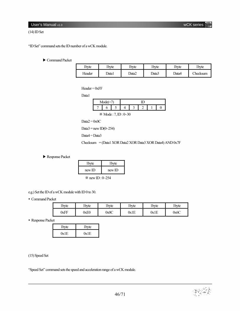
(14) ID Set
“ID Set” command sets the ID number of a wCK module.
▶Command Packet
1byte 1byte 1byte 1byte 1byte 1byte
Header Data1 Data2 Data3 Data4 Checksum
Header = 0xFF
Data1
Mode(=7) ID 7 6 5 4 3 2 1 0
Mode : 7, ID : 0~30※
Data2 = 0x0C
Data3 = new ID(0~254)
Data4 = Data3
Checksum = (Data1 XOR Data2 XOR Data3 XOR Data4) AND 0x7F
▶Response Packet
1byte 1byte
new ID new ID
new※ ID : 0~254
e.g.) Set the ID of a wCK module with ID 0 to 30.
Command Packet
1byte 1byte 1byte 1byte 1byte 1byte
0xFF 0xE0 0x0C 0x1E 0x1E 0x6C
Response Packet
1byte 1byte
0x1E 0x1E
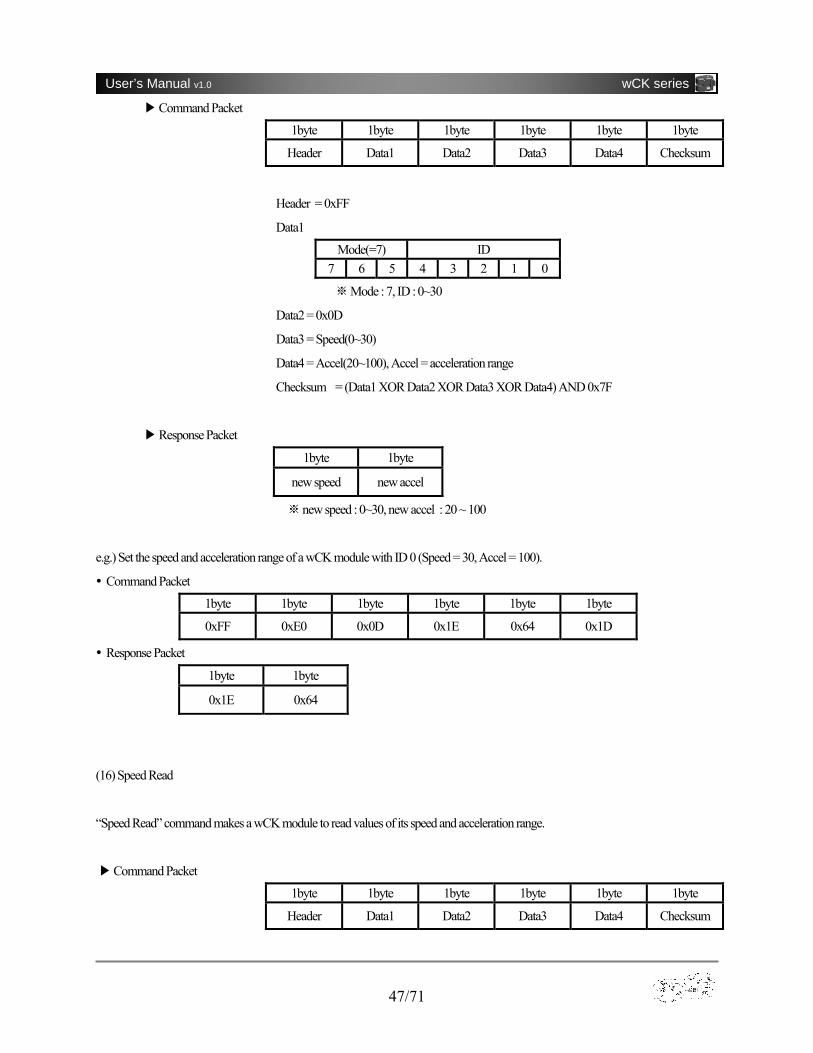
(15) Speed Set
“Speed Set” command sets the speed and acceleration range of a wCK module.
47/71
User’s Manual v1.0 wCK series
▶Command Packet
1byte 1byte 1byte 1byte 1byte 1byte
Header Data1 Data2 Data3 Data4 Checksum
Header = 0xFF
Data1
Mode(=7) ID 7 6 5 4 3 2 1 0
Mode : 7, ID : 0~30※
Data2 = 0x0D
Data3 = Speed(0~30)
Data4 = Accel(20~100), Accel = acceleration range
Checksum = (Data1 XOR Data2 XOR Data3 XOR Data4) AND 0x7F
▶Response Packet
1byte 1byte
new speed new accel
※new speed : 0~30, new accel : 20 ~ 100
e.g.) Set the speed and acceleration range of a wCK module with ID 0 (Speed = 30, Accel = 100).
Command Packet
1byte 1byte 1byte 1byte 1byte 1byte
0xFF 0xE0 0x0D 0x1E 0x64 0x1D
Response Packet
1byte 1byte
0x1E 0x64
(16) Speed Read
“Speed Read” command makes a wCK module to read values of its speed and acceleration range.
▶Command Packet
1byte 1byte 1byte 1byte 1byte 1byte
Header Data1 Data2 Data3 Data4 Checksum

48/71
User’s Manual v1.0 wCK series
Header = 0xFF
Data1
Mode(=7) ID 7 6 5 4 3 2 1 0
Mode : 7, ID : 0~30※
Data2 = 0x0E
Data3 = Arbitrary Value
Data4 = Arbitrary Value
Checksum = (Data1 XOR Data2 XOR Data3 XOR Data4) AND 0x7F
▶Response Packet
1byte 1byte
Speed Accel
※ speed : 0~30, accel : 20 ~ 100
e.g.) Command a wCK module with ID 0 to read its speed and acceleration range.
Command Packet
1byte 1byte 1byte 1byte 1byte 1byte
0xFF 0xE0 0x0E 0x00 0x00 0x6E
Response Packet
1byte 1byte
Speed Accel
(17) Runtime Speed Set
“Runtime Speed Set” command sets the runtime speed and acceleration range of a wCK module.
▶Command Packet
1byte 1byte 1byte 1byte 1byte 1byte
Header Data1 Data2 Data3 Data4 Checksum
Header = 0xFF
Data1
Mode(=7) ID 7 6 5 4 3 2 1 0
49/71
User’s Manual v1.0 wCK series
Mode : 7, ID : 0~30※
Data2 = 0x17
Data3 = Speed(0~30)
Data4 = Accel(20~100)
Checksum = (Data1 XOR Data2 XOR Data3 XOR Data4) AND 0x7F
▶Response Packet None
e.g.) Set the runtime speed and acceleration range of a wCK module with ID 0 (Speed = 30, Accel = 100).
Command Packet
1byte 1byte 1byte 1byte 1byte 1byte
0xFF 0xE0 0x17 0x1E 0x64 0x0D
Response Packet None
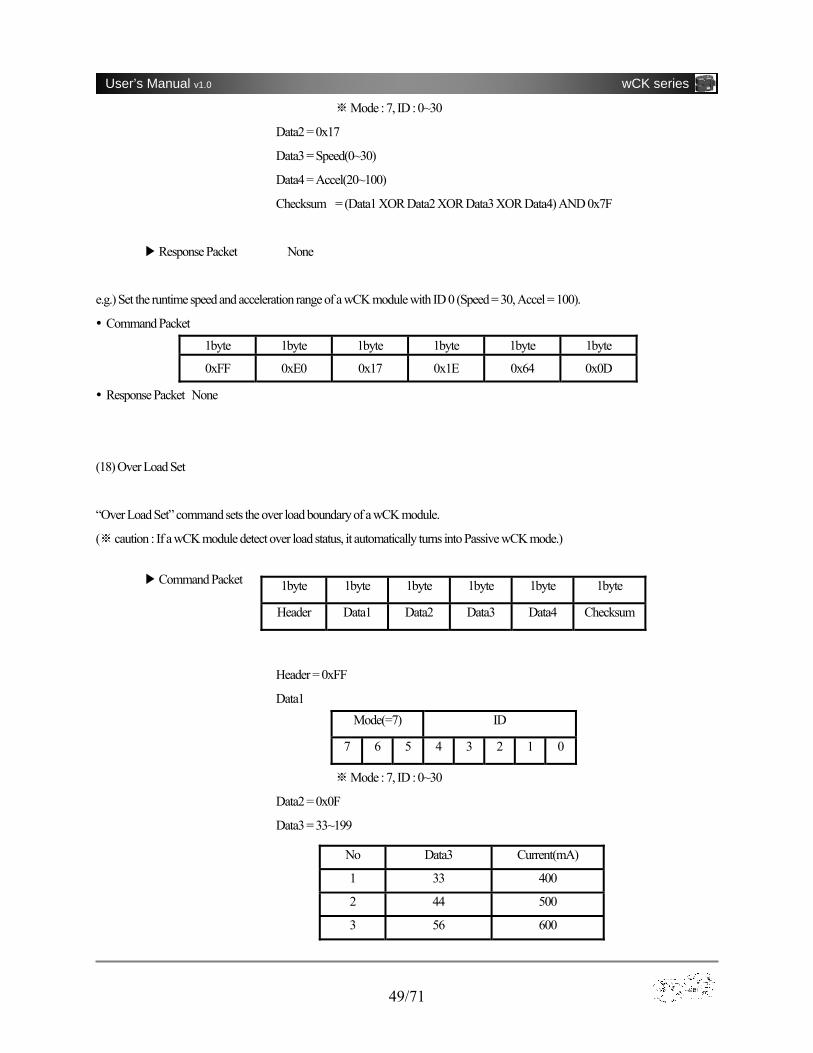
(18) Over Load Set
“Over Load Set” command sets the over load boundary of a wCK module.
( ※caution : If a wCK module detect over load status, it automatically turns into Passive wCK mode.)
▶Command Packet
Header = 0xFF
Data1 Mode(=7) ID
7 6 5 4 3 2 1 0
Mod※ e : 7, ID : 0~30
Data2 = 0x0F
Data3 = 33~199
1byte 1byte 1byte 1byte 1byte 1byte
Header Data1 Data2 Data3 Data4 Checksum
No Data3 Current(mA)
1 33 400
2 44 500
3 56 600
50/71
User’s Manual v1.0 wCK series
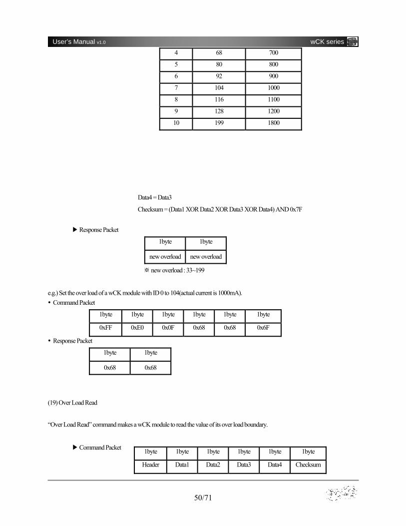
Data4 = Data3
Checksum = (Data1 XOR Data2 XOR Data3 XOR Data4) AND 0x7F
▶Response Packet
1byte 1byte
new overload new overload
new overload : ※ 33~199
e.g.) Set the over load of a wCK module with ID 0 to 104(actual current is 1000mA). Command Packet
1byte 1byte 1byte 1byte 1byte 1byte
0xFF 0xE0 0x0F 0x68 0x68 0x6F
Response Packet
1byte 1byte
0x68 0x68
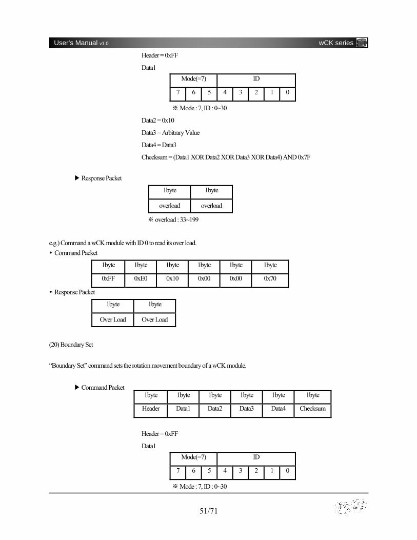
(19) Over Load Read
“Over Load Read” command makes a wCK module to read the value of its over load boundary.
▶Command Packet
4 68 700
5 80 800
6 92 900
7 104 1000
8 116 1100
9 128 1200
10 199 1800
1byte 1byte 1byte 1byte 1byte 1byte
Header Data1 Data2 Data3 Data4 Checksum
51/71
User’s Manual v1.0 wCK series
Header = 0xFF
Data1 Mode(=7) ID
7 6 5 4 3 2 1 0
Mode : 7, ID : 0~30※
Data2 = 0x10
Data3 = Arbitrary Value
Data4 = Data3
Checksum = (Data1 XOR Data2 XOR Data3 XOR Data4) AND 0x7F
▶Response Packet
1byte 1byte
overload overload
overload : 33~199※
e.g.) Command a wCK module with ID 0 to read its over load. Command Packet
1byte 1byte 1byte 1byte 1byte 1byte
0xFF 0xE0 0x10 0x00 0x00 0x70
Response Packet
1byte 1byte
Over Load Over Load
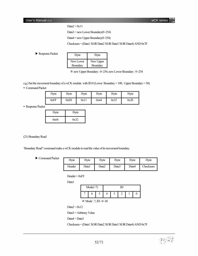
(20) Boundary Set “Boundary Set” command sets the rotation movement boundary of a wCK module.
▶Command Packet
Header = 0xFF
Data1 Mode(=7) ID
7 6 5 4 3 2 1 0
Mode : 7, ID : 0~30※
1byte 1byte 1byte 1byte 1byte 1byte
Header Data1 Data2 Data3 Data4 Checksum
52/71
User’s Manual v1.0 wCK series
Data2 = 0x11
Data3 = new Lower Boundary(0~254)
Data4 = new Upper Boundary(0~254)
Checksum = (Data1 XOR Data2 XOR Data3 XOR Data4) AND 0x7F
▶Response Packet
new Upper Boundary : 0~254, new Lower Boundary : 0~254※
e.g.) Set the movement boundary of a wCK module with ID 0 (Lower Boundary = 100, Upper Boundary = 50). Command Packet
1byte 1byte 1byte 1byte 1byte 1byte
0xFF 0xE0 0x11 0x64 0x32 0x20
Response Packet
1byte 1byte
0x64 0x32
(21) Boundary Read
‘Boundary Read” command make a wCK module to read the value of its movement boundary.
▶Command Packet
Header = 0xFF
Data1 Mode(=7) ID
7 6 5 4 3 2 1 0
Mode : 7, ID : 0~30※
Data2 = 0x12
Data3 = Arbitrary Value
Data4 = Data3
Checksum = (Data1 XOR Data2 XOR Data3 XOR Data4) AND 0x7F
1byte 1byte
New Lower Boundary
New Upper Boundary
1byte 1byte 1byte 1byte 1byte 1byte
Header Data1 Data2 Data3 Data4 Checksum
53/71
User’s Manual v1.0 wCK series
▶Response Packet
1byte 1byte
Lower Bound Upper Bound
new Upper Boundary : 0~254, new Lower Boundary : 0~254※
e.g.) Comand a wCK module with ID 0 to read its boundary values. Command Packet
1byte 1byte 1byte 1byte 1byte 1byte
0xFF 0xE0 0x12 0x00 0x00 0x72
Response Packet
1byte 1byte
Lower Boundary Upper Boundary
A-1-3 Extended Command
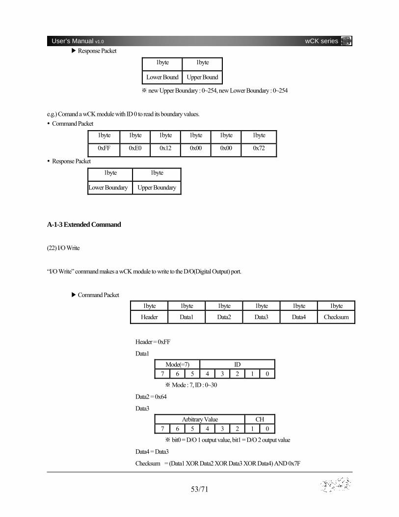
(22) I/O Write
“I/O Write” command makes a wCK module to write to the D/O(Digital Output) port.
▶Command Packet
1byte 1byte 1byte 1byte 1byte 1byte
Header Data1 Data2 Data3 Data4 Checksum
Header = 0xFF
Data1
Mode(=7) ID 7 6 5 4 3 2 1 0
Mode : 7, ID : 0~30※
Data2 = 0x64
Data3
Arbitrary Value CH 7 6 5 4 3 2 1 0
bit0 = D/O 1※ output value, bit1 = D/O 2 output value
Data4 = Data3
Checksum = (Data1 XOR Data2 XOR Data3 XOR Data4) AND 0x7F

54/71
User’s Manual v1.0 wCK series
▶Response Packet
1byte 1byte
D/O Value D/O Value
※D/O Value = Data3
e.g.) Command a wCK module with ID 0 to write the D/O values (CH1 = 1, CH2 = 1).
Command Packet
1byte 1byte 1byte 1byte 1byte 1byte
0xFF 0xE0 0x64 0x03 0x03 0x04
Response Packet
1byte 1byte
0x03 0x03
(23) I/O Read
“I/O Read” command make a wCK module to read the I/O data from external port.
▶Command Packet
1byte 1byte 1byte 1byte 1byte 1byte
Header Data1 Data2 Data3 Data4 Checksum
Header = 0xFF
Data1
Mode(=7) ID 7 6 5 4 3 2 1 0
Mode : 7, ID : 0~30※
Data2 = 0x65
Data3 = Arbitrary Value
Data4 = Data3
Checksum = (Data1 XOR Data2 XOR Data3 XOR Data4) AND 0x7F
▶Response Packet
1 byte 1 byte
D/O Value 8bit AD
55/71
User’s Manual v1.0 wCK series
※D/O Value structure
e.g.) Command a wCK module with ID 0 to read its I/O data.
Command Packet
1byte 1byte 1byte 1byte 1byte 1byte
0xFF 0xE0 0x65 0x00 0x00 0x04
Response Packet
1byte 1byte
Output Value 8bit AD
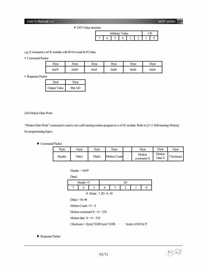
(24) Motion Data Write
“Motion Data Write” command is used to set a self-running motion program to a wCK module. Refer to [3-11 Self-running Motion]
for programming logics.
▶Command Packet
1byte 1byte 1byte 1byte 1byte 1byte 1byte
Header Data1 Data2 Motion Count ・ ・
・ Motion
command X Motion Data X Checksum
Header = 0xFF
Data1
Mode(=7) ID 7 6 5 4 3 2 1 0
Mode : 7, ID : 0~30※
Data2 = 0x 96
Motion Count = 0 ~ 8
Motion command X = 0 ~ 254
Motion data X = 0 ~ 254
Checksum = (byte2 XOR byte3 XOR ・ ・ ・ byten) AND 0x7f
▶Response Packet
Arbitrary Value CH 7 6 5 4 3 2 1 0

56/71
User’s Manual v1.0 wCK series
1byte 1byte
Motion Count Motion Count
Motion Count : 0 ~ 8
e.g.) Set a self-running motion to a wCK module with ID 0 (shuttle between position 82 and position 172).
Command Packet
1byte 1byte 1byte 1byte 1byte 1byte 1byte 1byte 1byte 1byte 1byte 1byte 1byte
0xFF 0xE0 0x96 0x04 0x10 0x52 0x31 0x0A 0x10 0xAC 0x31 0x0a 0x0c
Response Packet
1byte 1byte
0x04 0x04
(25) Motion Data Read
“Motion Data Read” command make a wCK module to read the number of instruction lines of a self-running motion program.
▶Command Packet
1byte 1byte 1byte 1byte 1byte 1byte
Header Data1 Data2 Data3 Data4 Checksum
Header = 0xFF
Data1 =
Mode(=7) ID 7 6 5 4 3 2 1 0
Mode : 7, ID : 0~30※
Data2 = 0x 97
Data3 = Arbitrary Value
Data4 = Data3
Checksum = (Data1 XOR Data2 XOR Data3 XOR Data4) AND 0x7F
▶Response Packet
1 byte 1 byte
Motion Count Motion Count
※Motion Count : 0 ~ 8
57/71
User’s Manual v1.0 wCK series
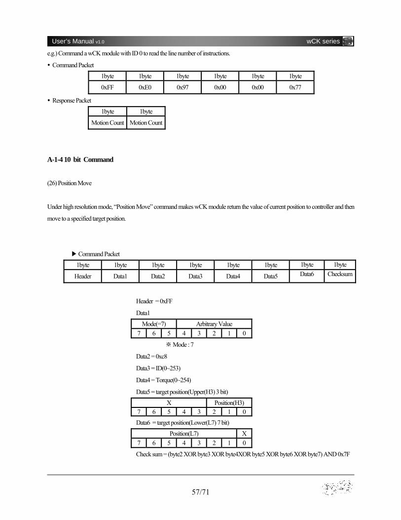
e.g.) Command a wCK module with ID 0 to read the line number of instructions.
Command Packet
1byte 1byte 1byte 1byte 1byte 1byte
0xFF 0xE0 0x97 0x00 0x00 0x77
Response Packet
1byte 1byte
Motion Count Motion Count
A-1-4 10 bit Command (26) Position Move
Under high resolution mode, “Position Move” command makes wCK module return the value of current position to controller and then
move to a specified target position.
▶Command Packet
1byte 1byte 1byte 1byte 1byte 1byte 1byte 1byte
Header Data1 Data2 Data3 Data4 Data5 Data6 Checksum
Header = 0xFF
Data1
Mode(=7) Arbitrary Value 7 6 5 4 3 2 1 0
※Mode : 7
Data2 = 0xc8
Data3 = ID(0~253)
Data4 = Torque(0~254)
Data5 = target position(Upper(H3) 3 bit)
X Position(H3) 7 6 5 4 3 2 1 0
Data6 = target position(Lower(L7) 7 bit)
Position(L7) X 7 6 5 4 3 2 1 0
Check sum = (byte2 XOR byte3 XOR byte4XOR byte5 XOR byte6 XOR byte7) AND 0x7F
58/71
User’s Manual v1.0 wCK series
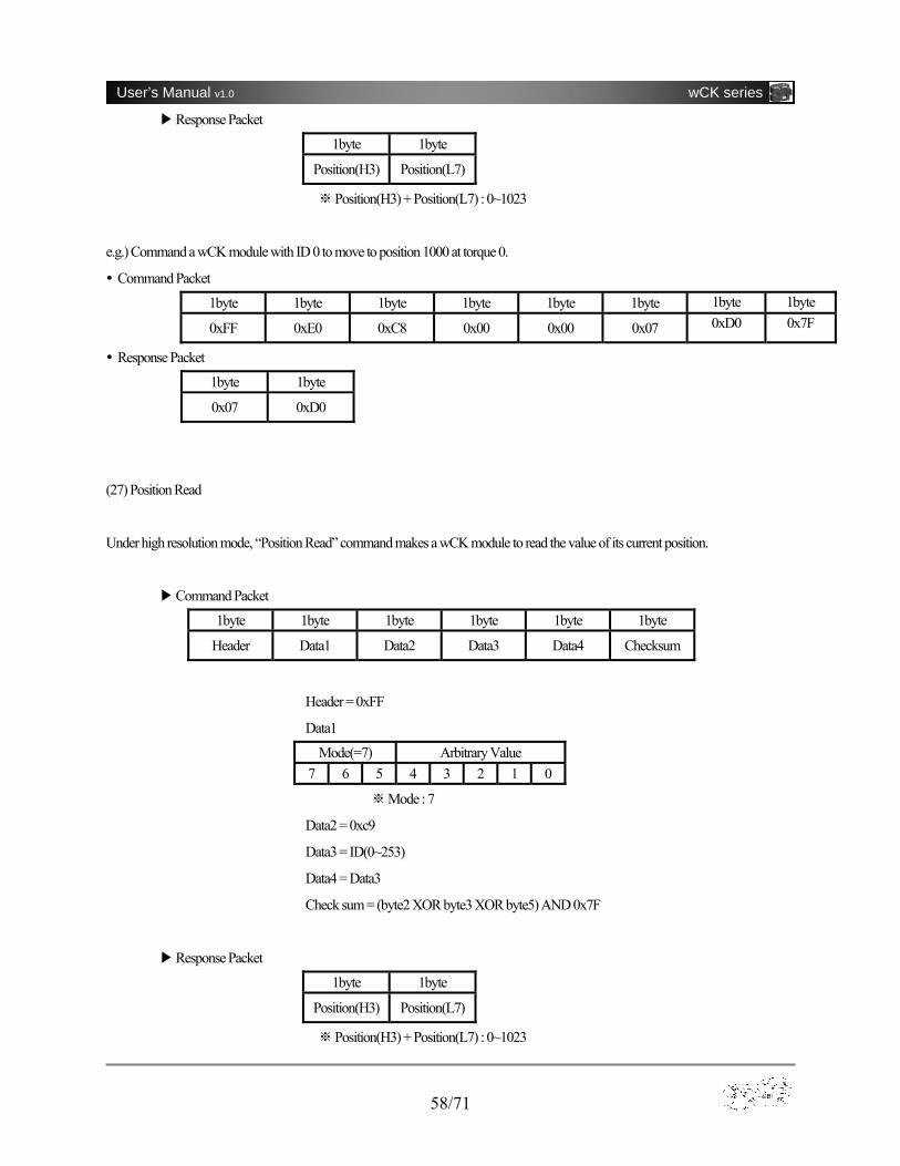
▶Response Packet
1byte 1byte
Position(H3) Position(L7)
※Position(H3) + Position(L7) : 0~1023
e.g.) Command a wCK module with ID 0 to move to position 1000 at torque 0.
Command Packet
1byte 1byte 1byte 1byte 1byte 1byte 1byte 1byte
0xFF 0xE0 0xC8 0x00 0x00 0x07 0xD0 0x7F
Response Packet
1byte 1byte
0x07 0xD0
(27) Position Read
Under high resolution mode, “Position Read” command makes a wCK module to read the value of its current position.
▶Command Packet
1byte 1byte 1byte 1byte 1byte 1byte
Header Data1 Data2 Data3 Data4 Checksum
Header = 0xFF
Data1
Mode(=7) Arbitrary Value 7 6 5 4 3 2 1 0
Mode : 7※
Data2 = 0xc9
Data3 = ID(0~253)
Data4 = Data3
Check sum = (byte2 XOR byte3 XOR byte5) AND 0x7F
▶Response Packet
1byte 1byte
Position(H3) Position(L7)
※ Position(H3) + Position(L7) : 0~1023
59/71
User’s Manual v1.0 wCK series
e.g.) Command a wCK module with ID 0 to read its position.
Command Packet
1byte 1byte 1byte 1byte 1byte 1byte
0xFF 0xE0 0xC9 0x00 0x00 0x29
Response Packet
1byte 1byte
Position(H3) Position(L7)
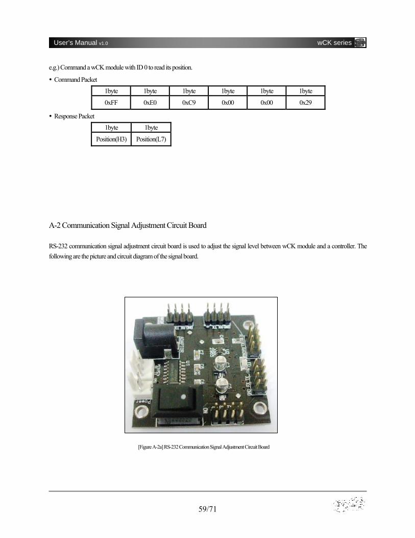
A-2 Communication Signal Adjustment Circuit Board RS-232 communication signal adjustment circuit board is used to adjust the signal level between wCK module and a controller. The following are the picture and circuit diagram of the signal board.
[Figure A-2a] RS-232 Communication Signal Adjustment Circuit Board

60/71
User’s Manual v1.0 wCK series
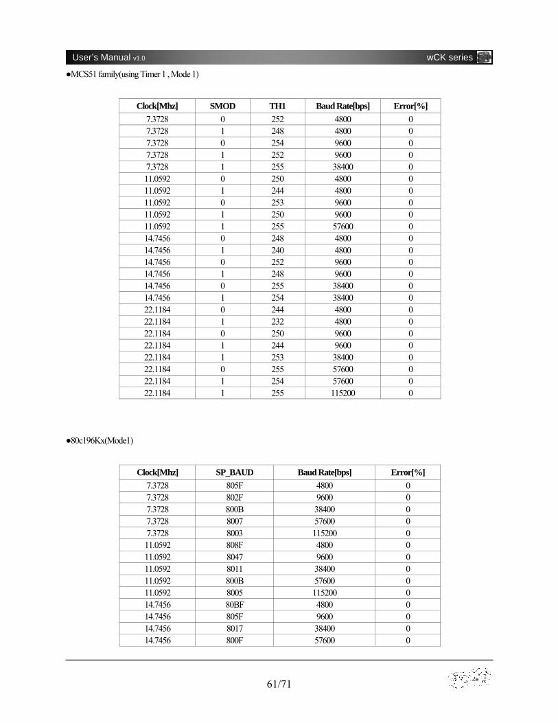
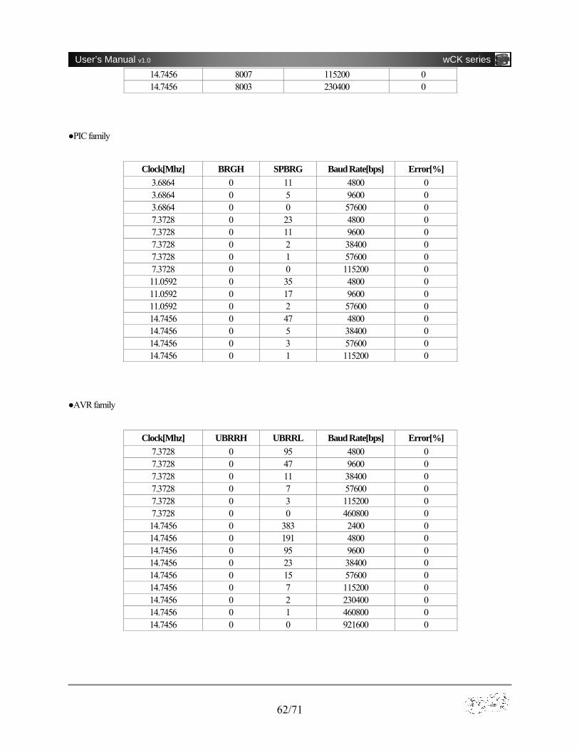
A-3 Baud rate setting for Independent Controller In case of using a MCU to control a wCK module, it’s recommended that a user refer to the following information in tables to minimize communication error.
VIN1
GND2
SD3BP 4
VOUT 5
U2
LP2985 C7103
C610uF R1
470
CR1LED
C810uF
C11uF
C21uF
C31uF
C4
1uF
+5V
13
45
11
10
12
9
2
6
14
7
13
8
16
15
U1
MAX232
C51uF
1234
5678
CN1
HEADER8B
1234
5678
CN3
HEADER8B
1234
5678
CN5
HEADER8B
1234
5678
CN4
HEADER8B
1234
5678
CN2
HEADER8B
VCC VCC
VCC VCC
VCC
VCC
VCC
VCC
VCC
VCC
2
1
3
4
5
SW1
POWER
1122
Battery_pack
123
Power_supply
VCC
112233
CN7
PC
+5VVCC
Rxd
Txd
TX_of_PC
RX_of_PC
TxdRxd
RxdTxd
RxdTxd
RxdTxd
RxdTxdTxd Txd
Txd
Txd
TxdRxd
Rxd
Rxd Rxd
Rxd
RX_of_PCTX_of_PC
[Figure A-2b] Circuit Diagram of Communication Board
61/71
User’s Manual v1.0 wCK series
●MCS51 family(using Timer 1 , Mode 1)
Clock[Mhz] SMOD TH1 Baud Rate[bps] Error[%] 7.3728 0 252 4800 0 7.3728 1 248 4800 0 7.3728 0 254 9600 0 7.3728 1 252 9600 0 7.3728 1 255 38400 0 11.0592 0 250 4800 0 11.0592 1 244 4800 0 11.0592 0 253 9600 0 11.0592 1 250 9600 0 11.0592 1 255 57600 0 14.7456 0 248 4800 0 14.7456 1 240 4800 0 14.7456 0 252 9600 0 14.7456 1 248 9600 0 14.7456 0 255 38400 0 14.7456 1 254 38400 0 22.1184 0 244 4800 0 22.1184 1 232 4800 0 22.1184 0 250 9600 0 22.1184 1 244 9600 0 22.1184 1 253 38400 0 22.1184 0 255 57600 0 22.1184 1 254 57600 0 22.1184 1 255 115200 0
●80c196Kx(Mode1)
Clock[Mhz] SP_BAUD Baud Rate[bps] Error[%] 7.3728 805F 4800 0 7.3728 802F 9600 0 7.3728 800B 38400 0 7.3728 8007 57600 0 7.3728 8003 115200 0 11.0592 808F 4800 0 11.0592 8047 9600 0 11.0592 8011 38400 0 11.0592 800B 57600 0 11.0592 8005 115200 0 14.7456 80BF 4800 0 14.7456 805F 9600 0 14.7456 8017 38400 0 14.7456 800F 57600 0
62/71
User’s Manual v1.0 wCK series
14.7456 8007 115200 0 14.7456 8003 230400 0
●PIC family
Clock[Mhz] BRGH SPBRG Baud Rate[bps] Error[%] 3.6864 0 11 4800 0 3.6864 0 5 9600 0 3.6864 0 0 57600 0 7.3728 0 23 4800 0 7.3728 0 11 9600 0 7.3728 0 2 38400 0 7.3728 0 1 57600 0 7.3728 0 0 115200 0 11.0592 0 35 4800 0 11.0592 0 17 9600 0 11.0592 0 2 57600 0 14.7456 0 47 4800 0 14.7456 0 5 38400 0 14.7456 0 3 57600 0 14.7456 0 1 115200 0
●AVR family
Clock[Mhz] UBRRH UBRRL Baud Rate[bps] Error[%] 7.3728 0 95 4800 0 7.3728 0 47 9600 0 7.3728 0 11 38400 0 7.3728 0 7 57600 0 7.3728 0 3 115200 0 7.3728 0 0 460800 0 14.7456 0 383 2400 0 14.7456 0 191 4800 0 14.7456 0 95 9600 0 14.7456 0 23 38400 0 14.7456 0 15 57600 0 14.7456 0 7 115200 0 14.7456 0 2 230400 0 14.7456 0 1 460800 0 14.7456 0 0 921600 0
63/71
User’s Manual v1.0 wCK series
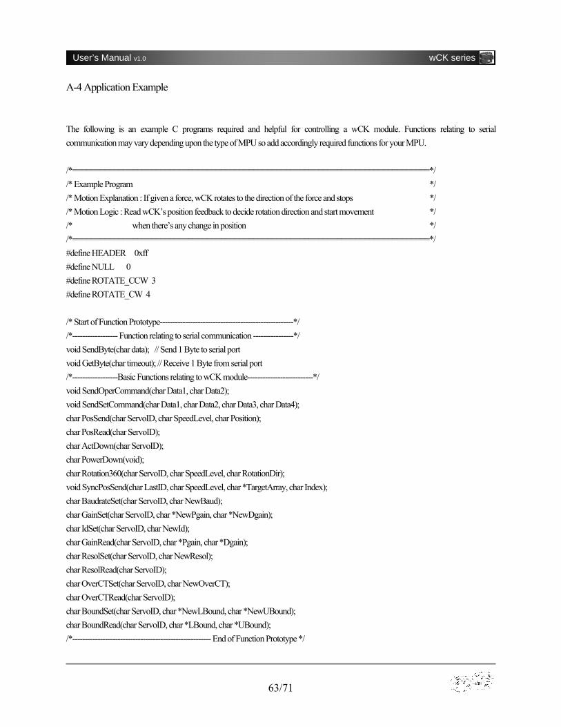
A-4 Application Example The following is an example C programs required and helpful for controlling a wCK module. Functions relating to serial communication may vary depending upon the type of MPU so add accordingly required functions for your MPU. /*=============================================================================*/ /* Example Program */ /* Motion Explanation : If given a force, wCK rotates to the direction of the force and stops */ /* Motion Logic : Read wCK’s position feedback to decide rotation direction and start movement */ /* when there’s any change in position */ /*=============================================================================*/ #define HEADER 0xff #define NULL 0 #define ROTATE_CCW 3 #define ROTATE_CW 4 /* Start of Function Prototype-----------------------------------------------------*/ /*------------------ Function relating to serial communication ----------------*/ void SendByte(char data); // Send 1 Byte to serial port void GetByte(char timeout); // Receive 1 Byte from serial port /*------------------Basic Functions relating to wCK module--------------------------*/ void SendOperCommand(char Data1, char Data2); void SendSetCommand(char Data1, char Data2, char Data3, char Data4); char PosSend(char ServoID, char SpeedLevel, char Position); char PosRead(char ServoID); char ActDown(char ServoID); char PowerDown(void); char Rotation360(char ServoID, char SpeedLevel, char RotationDir); void SyncPosSend(char LastID, char SpeedLevel, char *TargetArray, char Index); char BaudrateSet(char ServoID, char NewBaud); char GainSet(char ServoID, char *NewPgain, char *NewDgain); char IdSet(char ServoID, char NewId); char GainRead(char ServoID, char *Pgain, char *Dgain); char ResolSet(char ServoID, char NewResol); char ResolRead(char ServoID); char OverCTSet(char ServoID, char NewOverCT); char OverCTRead(char ServoID); char BoundSet(char ServoID, char *NewLBound, char *NewUBound); char BoundRead(char ServoID, char *LBound, char *UBound); /*------------------------------------------------------- End of Function Prototype */

64/71
User’s Manual v1.0 wCK series
void main(void) { char i, old_position; Initialize(); // Initialize peripheral devices(prepare for serial port) id = 0; old_position = ActDown(id); // Read the initial position of a wCK with ID 0 while(1) { now_position = ActDown(id); // Read current position // If position value decreased, rotate to ccw direction for 1 second and turn to passive mode for 1 second if(now_position<old_position) { Rotation360(id, 10, ROTATE_CCW); delay_ms(1000); ActDown(id); delay_ms(1000); } // If position value increased, rotate to cw direction for 1 second and turn to passive mode for 1 second else if(now_position>old_position) { Rotation360(id, 10, ROTATE_CW); delay_ms(1000); ActDown(id); delay_ms(1000); } old_position = ActDown(id); // Read current position and save it delay_ms(300); } } //////////////////////////////// Definition of Basic Functions /////////////////////////// /******************************************************************************/ /* Function that sends Operation Command Packet(4 Byte) to wCK module */ /* Input : Data1, Data2 */ /* Output : None */ /******************************************************************************/ void SendOperCommand(char Data1, char Data2) { char CheckSum; CheckSum = (Data1^Data2)&0x7f; SendByte(HEADER); SendByte(Data1); SendByte(Data2); SendByte(CheckSum);
65/71
User’s Manual v1.0 wCK series
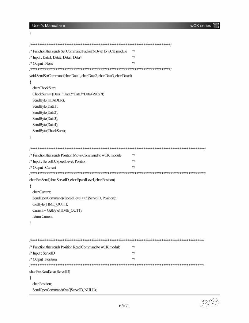
} /******************************************************************************/ /* Function that sends Set Command Packet(6 Byte) to wCK module */ /* Input : Data1, Data2, Data3, Data4 */ /* Output : None */ /******************************************************************************/ void SendSetCommand(char Data1, char Data2, char Data3, char Data4) { char CheckSum; CheckSum = (Data1^Data2^Data3^Data4)&0x7f; SendByte(HEADER); SendByte(Data1); SendByte(Data2); SendByte(Data3); SendByte(Data4); SendByte(CheckSum); } /*************************************************************************************************/ /* Function that sends Position Move Command to wCK module */ /* Input : ServoID, SpeedLevel, Position */ /* Output : Current */ /*************************************************************************************************/ char PosSend(char ServoID, char SpeedLevel, char Position) { char Current; SendOperCommand((SpeedLevel<<5)|ServoID, Position); GetByte(TIME_OUT1); Current = GetByte(TIME_OUT1); return Current; } /************************************************************************************************/ /* Function that sends Position Read Command to wCK module */ /* Input : ServoID */ /* Output : Position */ /************************************************************************************************/ char PosRead(char ServoID) { char Position; SendOperCommand(0xa0|ServoID, NULL);

66/71
User’s Manual v1.0 wCK series
GetByte(TIME_OUT1); Position = GetByte(TIME_OUT1); return Position; } /******************************************************************************/ /* Function that sends Passive wCK Command to wCK module */ /* Input : ServoID */ /* Output : Position */ /******************************************************************************/ char ActDown(char ServoID) { char Position; SendOperCommand(0xc0|ServoID, 0x10); GetByte(TIME_OUT1); Position = GetByte(TIME_OUT1); return Position; } /*************************************************************************/ /* Function that sends Break wCK Command to wCK module */ /* Input : None */ /* Output : ServoID if succeed, 0xff if fail */ /**************************************************************************/ char PowerDown(void) { char ServoID; SendOperCommand(0xdf, 0x20); ServoID = GetByte(TIME_OUT1); GetByte(TIME_OUT1); if(ServoID<31) return ServoID; return 0xff; //Receive error } /******************************************************************/ /* Function that sends 360 degree Wheel wCK Command */ /* Input : ServoID, SpeedLevel, RotationDir */ /* Return : Rotation Number */ /*****************************************************************/ char Rotation360(char ServoID, char SpeedLevel, char RotationDir) { char ServoPos, RotNum; if(RotationDir==ROTATE_CCW) {
67/71
User’s Manual v1.0 wCK series
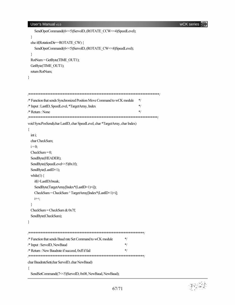
SendOperCommand((6<<5)|ServoID, (ROTATE_CCW<<4)|SpeedLevel); } else if(RotationDir==ROTATE_CW) { SendOperCommand((6<<5)|ServoID, (ROTATE_CW<<4)|SpeedLevel); } RotNum = GetByte(TIME_OUT1); GetByte(TIME_OUT1); return RotNum; } /*****************************************************************************/ /* Function that sends Synchronized Position Move Command to wCK module */ /* Input : LastID, SpeedLevel, *TargetArray, Index */ /* Return : None */ /****************************************************************************/ void SyncPosSend(char LastID, char SpeedLevel, char *TargetArray, char Index) { int i; char CheckSum; i = 0; CheckSum = 0; SendByte(HEADER); SendByte((SpeedLevel<<5)|0x1f); SendByte(LastID+1); while(1) { if(i>LastID) break; SendByte(TargetArray[Index*(LastID+1)+i]); CheckSum = CheckSum ̂ TargetArray[Index*(LastID+1)+i]; i++; } CheckSum = CheckSum & 0x7f; SendByte(CheckSum); } /********************************************************************/ /* Function that sends Baud rate Set Command to wCK module */ /* Input : ServoID, NewBaud */ /* Return : New Baudrate if succeed, 0xff if fail */ /********************************************************************/ char BaudrateSet(char ServoID, char NewBaud) { SendSetCommand((7<<5)|ServoID, 0x08, NewBaud, NewBaud);

68/71
User’s Manual v1.0 wCK series
GetByte(TIME_OUT2); if(GetByte(TIME_OUT2)==NewBaud) return NewBaud; return 0xff; } /*********************************************************************/ /* Function that sends Gain Set Command to wCK module */ /* Input : ServoID, *NewPgain, *NewDgain */ /* Return : 1 if succeed, 0 if fail */ /********************************************************************/ char GainSet(char ServoID, char *NewPgain, char *NewDgain) { char Data1,Data2; SendSetCommand((7<<5)|ServoID, 0x09, *NewPgain, *NewDgain); Data1 = GetByte(TIME_OUT2); Data2 = GetByte(TIME_OUT2); if((Data1==*NewPgain) && (Data2==*NewDgain)) return 1; return 0; } /************************************************************/ /* Function that sends ID Set Command to wCK module */ /* Input : ServoID, NewId */ /* Return : New ID if succeed, 0xff if fail */ /***********************************************************/ char IdSet(char ServoID, char NewId) { SendSetCommand((7<<5)|ServoID, 0x0a, NewId, NewId); GetByte(TIME_OUT2); if(GetByte(TIME_OUT2)==NewId) return NewId; return 0xff; } /******************************************************************/ /* Function that sends Gain Read Command to wCK module */ /* Input : ServoID, *NewPgain, *NewDgain */ /* Return : 1 if succeed, 0 if fail */ /*****************************************************************/ char GainRead(char ServoID, char *Pgain, char *Dgain) { SendSetCommand((7<<5)|ServoID, 0x0c, 0, 0); *Pgain = GetByte(TIME_OUT1);

69/71
User’s Manual v1.0 wCK series
*Dgain = GetByte(TIME_OUT1); if((*Pgain>0) && (*Pgain<51) && (*Dgain<101)) return 1; return 0; } /**********************************************************************************/ /* Function that sends Over Load Set Command to wCK module */ /* Input : ServoID, NewOverCT */ /* Return : New Overcurrent Threshold if succeed, 0xff if fail */ /**********************************************************************************/ char OverCTSet(char ServoID, char NewOverCT) { char Data1; SendSetCommand((7<<5)|ServoID, 0x0f, NewOverCT, NewOverCT); sciRxReady(TIME_OUT2); Data1=sciRxReady(TIME_OUT2); if(Data1!=0xff) return Data1; return 0xff; } /******************************************************************************/ /* Function that sends Over Load Read Command to wCK module */ /* Input : ServoID */ /* Return : Overcurrent Threshold if succeed, 0xff if fail */ /******************************************************************************/ char OverCTRead(char ServoID) { char Data1; SendSetCommand((7<<5)|ServoID, 0x10, 0, 0); sciRxReady(TIME_OUT1); Data1=sciRxReady(TIME_OUT1); if(Data1!=0xff) return Data1; return 0xff; } /***********************************************************************/ /* Function that sends Boundary Set Command to wCK module */ /* Input : ServoID, *NewLBound, *NewUBound */ /* Return : 1 if succeed, 0 if fail */ /**********************************************************************/ char BoundSet(char ServoID, char *NewLBound, char *NewUBound) { char Data1,Data2;

70/71
User’s Manual v1.0 wCK series
SendSetCommand((7<<5)|ServoID, 0x11, *NewLBound, *NewUBound); Data1 = GetByte(TIME_OUT2); Data2 = GetByte(TIME_OUT2); if((Data1==*NewLBound) && (Data2==*NewUBound)) return 1; return 0; } /**************************************************************************/ /* Function that sends Boundary Read Command to wCK module */ /* Input : ServoID, *NewLBound, *NewUBound */ /* Return : 1 if succeed, 0 if fail */ /*************************************************************************/ char BoundRead(char ServoID, char *LBound, char *UBound) { SendSetCommand((7<<5)|ServoID, 0x12, 0, 0); *LBound = GetByte(TIME_OUT1); *UBound = GetByte(TIME_OUT1); if(*LBound<*UBound) return 1; return 0; } //////////////////////////////// End of Basic Functions Definition ///////////////////////////// A-5 Default Parameter Settings Baud Rate 7 (115,200 bps) P gain 20 D gain 30 I gain 0 wCK module ID 0 Movement Speed 0 (No speed limit) Acceleration Range 60 Over-current 33 (400mA) Control Angle Range 1, 254 (1~254) Motion Program Writing 0 (Self-running Motion inactivated)
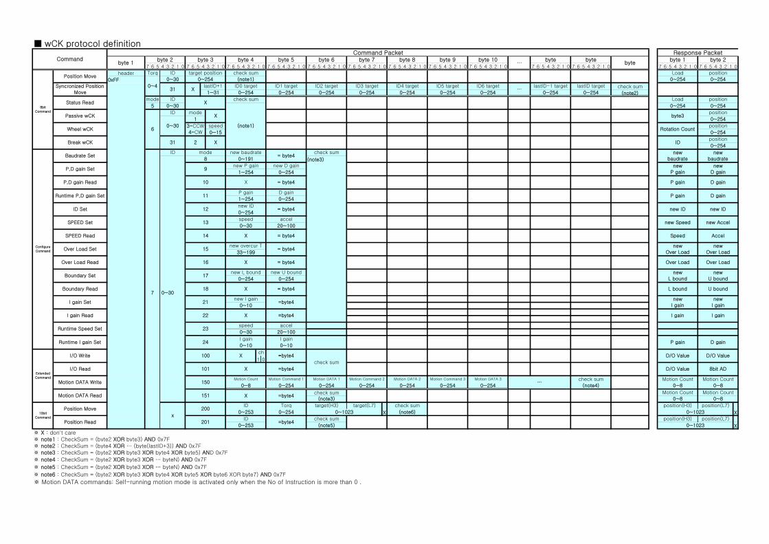
■ wCK protocol definition
7 6 5 4 3 2 1 0 7 6 5 4 3 2 1 0 7 6 5 4 3 2 1 0 7 6 5 4 3 2 1 0 7 6 5 4 3 2 1 0 7 6 5 4 3 2 1 0 7 6 5 4 3 2 1 0 7 6 5 4 3 2 1 0 7 6 5 4 3 2 1 0 7 6 5 4 3 2 1 0 7 6 5 4 3 2 1 0 7 6 5 4 3 2 1 0 7 6 5 4 3 2 1 0
header
0xFF
check sum
(note2)
(note3)
7 0~30
1 0
X X
X
※ X : don't care※ note1 : CheckSum = (byte2 XOR byte3) AND 0x7F※ note2 : CheckSum = (byte4 XOR … (byte(lastID+3)) AND 0x7F※ note3 : CheckSum = (byte2 XOR byte3 XOR byte4 XOR byte5) AND 0x7F
※ note4 : CheckSum = (byte2 XOR byte3 XOR … byteN) AND 0x7F
※ note5 : CheckSum = (byte2 XOR byte3 XOR … byteN) AND 0x7F
※ note6 : CheckSum = (byte2 XOR byte3 XOR byte4 XOR byte5 XOR byte6 XOR byte7) AND 0x7F
※ Motion DATA commands: Self-running motion mode is activated only when the No of Instruction is more than 0 .
P gain D gain
Runtime I gain Set 24I gain I gain
P gain D gain0~10 0~10
0~1023
position(H3) position(L7)check sum
(note5)
ID=byte4
0~253
position(L7)
0~253 0~254 0~1023 (note6) 0~1023
position(H3)check sum
10bit
Command
Position Move
x
200ID Torq target(H3)
Position Read 201
target(L7)
0~8
Motion Count Motion Count=byte4
check sum(note3)
0~8
0~8
Motion Count Motion Count
0~80~8 0~254 0~254 0~254 0~254 0~254 0~254
Motion DATA 3…
check sum
(note4)
D/O Value 8bit AD
Motion DATA Write 150Motion Count Motion Command 1 Motion DATA 1 Motion Command 2 Motion DATA 2 Motion Command 3
X =byte4
D/O Value D/O Value=byte4
check sum
Extended
Command
I/O Write 100 X
Motion DATA Read 151 X
ch
I/O Read 101
Runtime Speed Set 23speed accel
0~30 20~100
I gain I gainI gain Read 22 X =byte4
newI gain
newI gain
L bound U bound
I gain Set 21new I gain
=byte40~10
newU bound0~254 0~254
Boundary Read 18 X = byte4
newL bound
Over Load
Boundary Set 17new L bound new U bound
Over Load16 X = byte4
newOver Load33~199
newOver Load
Speed Accel
Over Load Set 15new overcur T
= byte4
SPEED Read 14 X = byte4
new Speed new Accel0~30 20~100
SPEED Set 13speed accel
new ID new IDnew ID
= byte40~254
Runtime P,D gain Set 11P gain D gain
1~254 0~254
P gain D gainX = byte4
newbaudrate
newbaudrate
newD gain
newP gain
8 0~191
new baudrate= byte4
check sum
new D gain
1~254 0~254
Configure
Comnand
Baudrate SetID mode
P,D gain Set
P,D gain Read 10
9new P gain
position
ID Set 12
Over Load Read
0~254IDX
0~15 0~254Rotation Count
position
position
0~30
1 0~254
3=CCW4=CW
speed
byte3XPassive wCK
6
ID mode
Wheel wCK
Break wCK 31 2
position
0~2545 0~30
(note1)
0~254
Loadcheck sumStatus Read
mode IDX
1~31 0~254 0~254 0~254 0~254 0~254 0~254 0~254 0~254…
lastID-1 target lastID target
0~254
ID3 target ID4 target ID5 target ID6 targetSyncronized Position Move
31 XlastID+1
position
0~4
0~30 0~254 (note1) 0~254 0~254
ID0 target ID1 target ID2 target
Load
byte 2
8bit
Command
Position MoveTorq ID target position check sum
byte bytebyte
byte 1byte 8 byte 9 byte 10…
CommandCommand Packet Response Packet
byte 1byte 2 byte 3 byte 4 byte 5 byte 6 byte 7