user’s manual minimax - srs20assets-qa.service … · user’s manual spx corporation •...
TRANSCRIPT
MINIMAX
REFRIGERANT RECOVERY MACHINE
USER’S MANUAL
SPX Corporation • Owatonna, MNToll Free: (800) 327-5060 • Fax: (866) 287-7222
www.PromaxRecovery.com
TM
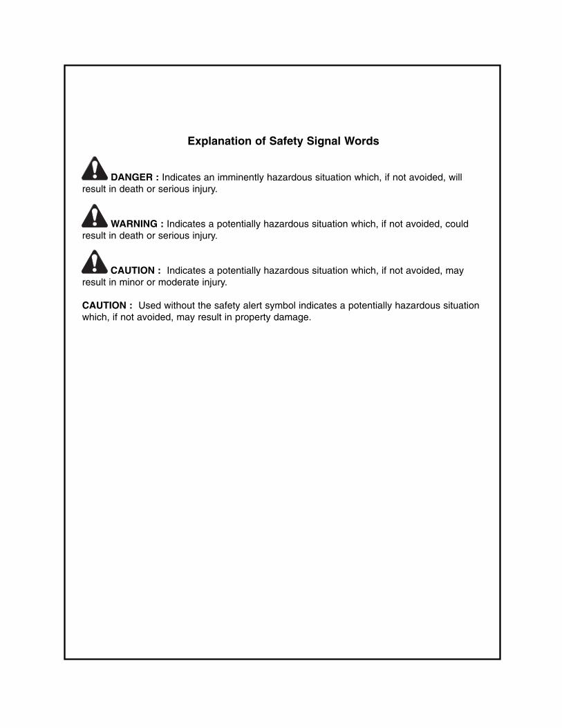
Explanation of Safety Signal Words
DANGER : Indicates an imminently hazardous situation which, if not avoided, willresult in death or serious injury.
WARNING : Indicates a potentially hazardous situation which, if not avoided, couldresult in death or serious injury.
CAUTION : Indicates a potentially hazardous situation which, if not avoided, mayresult in minor or moderate injury.
CAUTION : Used without the safety alert symbol indicates a potentially hazardous situationwhich, if not avoided, may result in property damage.

TABLE OF CONTENTS
3
Safety Precautions . . . . . . . . . . . . . . . . . . . . . . . . . . . . . . . . . . . . . . . . . . . . . . . .4
Understanding Refrigerant Recovery . . . . . . . . . . . . . . . . . . . . . . . . . . . . . . . . . . .5
Recovery Tank Information . . . . . . . . . . . . . . . . . . . . . . . . . . . . . . . . . . . . . . . . . .6
Purging Non-condensable Gases . . . . . . . . . . . . . . . . . . . . . . . . . . . . . . . . . . . . .7
Maintenance . . . . . . . . . . . . . . . . . . . . . . . . . . . . . . . . . . . . . . . . . . . . . . . . . . . . .8
Operating Instructions . . . . . . . . . . . . . . . . . . . . . . . . . . . . . . . . . . . . . . . . . . . . . .9
Minimax Self-Purge . . . . . . . . . . . . . . . . . . . . . . . . . . . . . . . . . . . . . . . . . . . . . . .10
Push/Pull Method Instructions . . . . . . . . . . . . . . . . . . . . . . . . . . . . . . . . . . . . . . .11
Tank Pre- or Sub-cooling Instructions . . . . . . . . . . . . . . . . . . . . . . . . . . . . . . . . .12
Recovery / Tank Pre- or Sub-Cooling for Fixed Hose Set-up . . . . . . . . . . . . . . . .12
Refrigerant Recycling . . . . . . . . . . . . . . . . . . . . . . . . . . . . . . . . . . . . . . . . . . . . .13
Parts List . . . . . . . . . . . . . . . . . . . . . . . . . . . . . . . . . . . . . . . . . . . . . . . . . . . . . .14
Replacement Kits and Accessories . . . . . . . . . . . . . . . . . . . . . . . . . . . . . . . . . . .14
Minimax Wiring Diagram . . . . . . . . . . . . . . . . . . . . . . . . . . . . . . . . . . . . . . . . . . .15
Minimax-KT Wiring Diagram . . . . . . . . . . . . . . . . . . . . . . . . . . . . . . . . . . . . . . . .15
Installation of Optional 80% Tank Capacity Sensing Components (Kit KT-5001) . .16
Troubleshooting . . . . . . . . . . . . . . . . . . . . . . . . . . . . . . . . . . . . . . . . . . . . . . . . .17
One-Year Warranty . . . . . . . . . . . . . . . . . . . . . . . . . . . . . . . . . . . . . . . . . . . . . . .18
EPA Certification Form . . . . . . . . . . . . . . . . . . . . . . . . . . . . . . . . . . . . . . . . . . . .19
Environmental Protection Agency (EPA) Instructions . . . . . . . . . . . . . . . . . . . . . .20
EPA Regional Offices . . . . . . . . . . . . . . . . . . . . . . . . . . . . . . . . . . . . . . . . . . . . .20
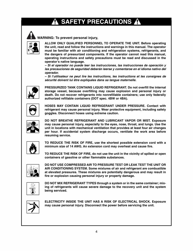
SAFETY PRECAUTIONS
4
ALLOW ONLY QUALIFIED PERSONNEL TO OPERATE THE UNIT. Before operatingthe unit, read and follow the instructions and warnings in this manual. The operatormust be familiar with air conditioning and refrigeration systems, refrigerants, andthe dangers of pressurized components. If the operator cannot read this manual,operating instructions and safety precautions must be read and discussed in theoperator’s native language.– Si el operador no puede leer las instrucciones, las instrucciones de operación ylas precauciones de seguridad deberán leerse y comentarse en el idioma nativo deloperador.– Si l’utilisateur ne peut lire les instructions, les instructions et les consignes desécurité doivent lui être expliquées dans sa langue maternelle.
PRESSURIZED TANK CONTAINS LIQUID REFRIGERANT. Do not overfill the internalstorage vessel, because overfilling may cause explosion and personal injury ordeath. Do not recover refrigerants into nonrefillable containers; use only federallyauthorized refillable containers (DOT spec. 4BW or 4BA).
HOSES MAY CONTAIN LIQUID REFRIGERANT UNDER PRESSURE. Contact withrefrigerant may cause personal injury. Wear protective equipment, including safetygoggles. Disconnect hoses using extreme caution.
DO NOT BREATHE REFRIGERANT AND LUBRICANT VAPOR OR MIST. Exposuremay cause personal injury, especially to the eyes, nose, throat, and lungs. Use theunit in locations with mechanical ventilation that provides at least four air changesper hour. If accidental system discharge occurs, ventilate the work area beforeresuming service.
TO REDUCE THE RISK OF FIRE, use the shortest possible extension cord with aminimum size of 14 AWG. An extension cord may overheat and cause fire.
TO REDUCE THE RISK OF FIRE, do not use the unit in the vicinity of spilled or opencontainers of gasoline or other flammable substances.
DO NOT USE COMPRESSED AIR TO PRESSURE TEST OR LEAK TEST THE UNIT ORAIR CONDITIONING SYSTEM. Some mixtures of air and refrigerant are combustibleat elevated pressures. These mixtures are potentially dangerous and may result infire or explosion causing personal injury or property damage.
DO NOT MIX REFRIGERANT TYPES through a system or in the same container; mix-ing of refrigerants will cause severe damage to the recovery unit and the systembeing serviced.
ELECTRICITY INSIDE THE UNIT HAS A RISK OF ELECTRICAL SHOCK. Exposuremay cause personal injury. Disconnect the power before servicing the unit.
WARNING: To prevent personal injury,

UNDERSTANDING REFRIGERANT RECOVERY
5
Refrigerant recovery is the process of taking refrig-erant out of a system and storing it in a tank. Thefollowing is critical information on how to achievethe best refrigerant recovery results safely andquickly.
1. Identify the refrigerant type and quantity in thesystem that is to be serviced.
2. Minimax is approved for use with the followingcatagory III, IV, and V refrigerants (Per ARI740):
R-12 R-402A R-407C R-411BR-22 R-402-B R-407D R-412R-134A R-404A R-408A R-500R-401A R-406A R-409A R-502R-401B R-407A R-410A R-507R-401C R-407-B R-411A R-509
3. CAUTION: A filter must always be usedand replaced frequently. Failure to use a fil-ter will invalidate your warranty. It is rec-ommended that a clean filter be used forevery service job. A filter will prevent con-tamination from entering the Minimax,which will reduce the risk of damage. Eachfilter needs to be labeled and used for onetype of refrigerant only.
4. WARNING: Open service and cylindervalves slowly. This allows for rapid shut offof gas flow if there is any danger. Once it isdetermined that there is no danger, thevalves can be opened fully.
5. Isolate large amounts of refrigerant and closeoff valves after use. If a leak develops in thesystem, the refrigerant will not escape.
6. CAUTION: Keep all connections to therefrigeration system dry and clean.Damage will occur if moisture is allowed toenter the system.
7. Promax strongly recommends the use of theoptional 80% Capacity Shutoff Kit (#KT-5001).When installed and used with a recovery tankthat has an internal float switch, the Minimax
shuts down automatically when the tank is80% full. The Minimax is pre-wired for this kitfrom the factory. The Minimax-KT is availablewith the 80% Capacity Shutoff Kit installed.
8. Minimax has an internal pressure shutoffswitch. If the system pressure goes above 550psi, the unit shuts off. The shutoff switch auto-matically resets itself after the pressure dropsbelow 300 psi.
WARNING: The internal pressureshutoff switch does not prevent tank over-fill. If the Minimax shuts off automaticallyand is connected to a tank, the tank may bedangerously overfilled. Relieve this highpressure and/or tank overfill situationimmediately.
9. If tank pressure exceeds 300 psi, use the tankcooling process to reduce the tank pressure.Refer to pages 11 & 12.
10. When recovering large amounts (20 lbs. ormore) of liquid refrigerant, use the Push/Pullmethod as described on page 11.
11. All refrigerant systems are likely to have areaswhere the liquid can be trapped and slow therecovery process significantly. Refer to page 9for how to locate and recover trapped liquidrefrigerant.
12. To achieve the deepest final vacuum, use thetank cooling method to lower the head pres-sure on a recovery tank (see pages 11 & 12).NOTE: The cooling method will not work ifthere is no liquid in the recovery tank. In thiscase, use an empty tank that has been fullyevacuated to achieve the final vacuum levelrequired.
13. To maximize recovery rates, use the shortesthose length possible (no longer than 3 ft. isrecommended) and 3/8" diameter (or larger).Remove all unnecessary hose core depres-sors and Schrader valves from all port con-nections as these can restrict flow up to 90%.
1. NEVER use a standard disposable 30 lb. tank(the type of container in which virgin refrigerantis sold) to recover refrigerant. Use ONLYauthorized refillable refrigerant tanks. Federalregulations require refrigerant to be transport-ed only in containers meeting DOT specs.4BW or 4BA.
2. Warning: To prevent personal injury, donot exceed the working pressure of eachcylinder. Recovery cylinders are designed fordifferent pressures. The Minimax is not sup-plied with a recovery tank, and requires theuse of tanks with a minimum of 350 psi work-ing pressure. PROMAX strongly recommendsthe use of 400 psi tanks.
NOTE: When recovering R-410A refrigerantuse of a 400 psi tank is mandatory. (See PRO-MAX Recovery Tanks under Parts andAccessories section on Page 14.)
3. Tanks and filters must be designated for one
type of refrigerant only. Before using a tankpreviously used for another refrigerant, com-pletely empty the tank, and evacuate it. Thenpurge the tank using dry nitrogen, and evacu-ate again.
4. Store refrigerant containers in a cool, dryplace.
5. Some storage cylinders have valves that arenot seated when manufactured. Keeping capson valves will guard against refrigerant leak-age.
6. Do not exceed 80% of tank capacity. PROMAXstrongly recommends the use of the PromaxADS-100 Refrigerant Scale for monitoring tankcapacity. Safety codes recommend that closedtanks not be filled over 80% of volume with liq-uid. The remaining 20% is called head pres-sure room.
7. If you expect temperatures in excess of 135° F,contact the refrigerant supplier.
RECOVERY TANK INFORMATION
6
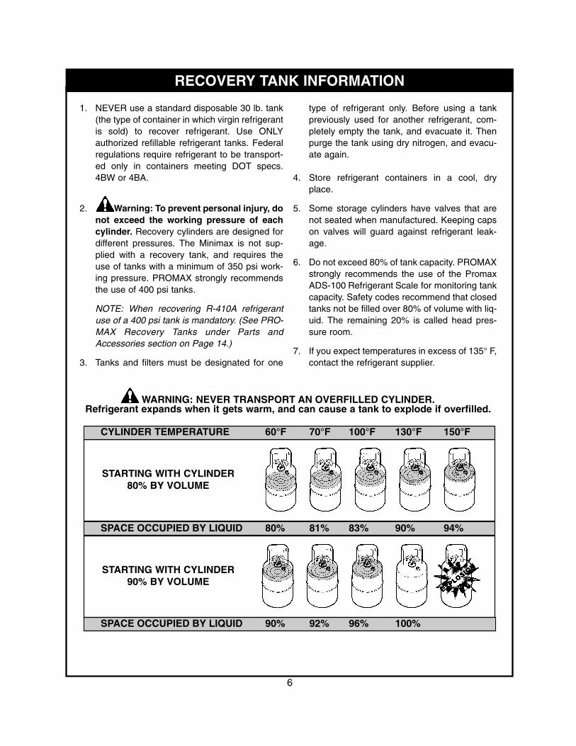
WARNING: NEVER TRANSPORT AN OVERFILLED CYLINDER.Refrigerant expands when it gets warm, and can cause a tank to explode if overfilled.
CYLINDER TEMPERATURE 60°F 70°F 100°F 130°F 150°F
STARTING WITH CYLINDER80% BY VOLUME
SPACE OCCUPIED BY LIQUID 80% 81% 83% 90% 94%
STARTING WITH CYLINDER90% BY VOLUME
SPACE OCCUPIED BY LIQUID 90% 92% 96% 100%

7
1. Allow the tank to sit undisturbed for 24 hoursto let any air rise to the top.
2. Connect a manifold to the tank to read theamount of pressure in the tank.
3. Determine the ambient temperature in theroom.
4. Refer to a refrigerant pressure/temperaturechart. Find the temperature on the chart andlook across to the corresponding pressure forthe type of refrigerant in the tank. Determinehow that relates to the reading on the gauge.
5. If the pressure reading is higher than the pres-sure shown on the chart, very slowly (to causeas little turbulence inside the tank as possible)open the vapor port valve slightly. Watch thepressure on the gauge decrease. To preventventing, add 4-5 psi to the pressure shown onthe chart. When the gauge corresponds to thatpressure, close the vapor port valve.
6. Allow the tank to sit for 10 minutes, then checkthe pressure again.
7. Repeat the process as needed.
PURGING NON-CONDENSABLE GASESFROM REFRIGERANT TANKS
8
MAINTENANCE
WARNING: To prevent personal injury,
• Disconnect the Minimax from its power supply before beginning any maintenance.
CAUTION: To prevent equipment damage,
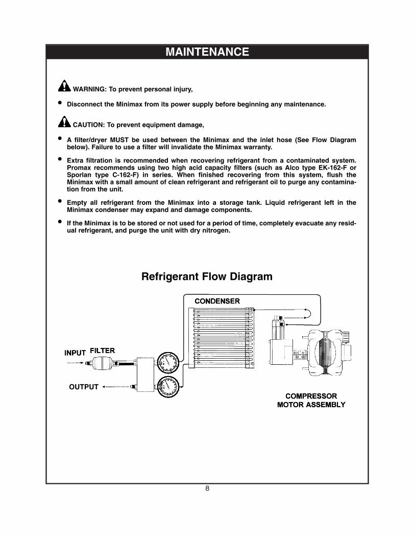
• A filter/dryer MUST be used between the Minimax and the inlet hose (See Flow Diagrambelow). Failure to use a filter will invalidate the Minimax warranty.
• Extra filtration is recommended when recovering refrigerant from a contaminated system.Promax recommends using two high acid capacity filters (such as Alco type EK-162-F orSporlan type C-162-F) in series. When finished recovering from this system, flush theMinimax with a small amount of clean refrigerant and refrigerant oil to purge any contamina-tion from the unit.
• Empty all refrigerant from the Minimax into a storage tank. Liquid refrigerant left in theMinimax condenser may expand and damage components.
• If the Minimax is to be stored or not used for a period of time, completely evacuate any resid-ual refrigerant, and purge the unit with dry nitrogen.
Refrigerant Flow Diagram
OUTPUT
OPERATING INSTRUCTIONS
1. Inspect the Minimax thoroughly to ensure it isin good operating condition.
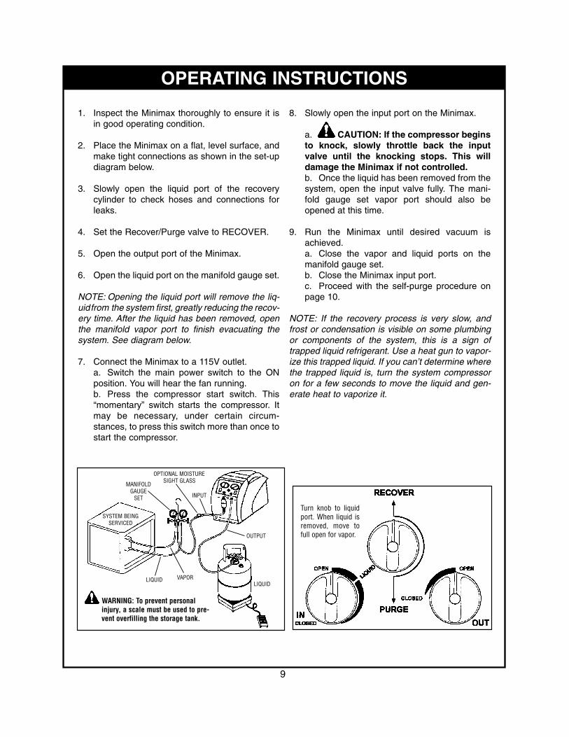
2. Place the Minimax on a flat, level surface, andmake tight connections as shown in the set-updiagram below.
3. Slowly open the liquid port of the recoverycylinder to check hoses and connections forleaks.
4. Set the Recover/Purge valve to RECOVER.
5. Open the output port of the Minimax.
6. Open the liquid port on the manifold gauge set.
NOTE: Opening the liquid port will remove the liq-uidfrom the system first, greatly reducing the recov-ery time. After the liquid has been removed, openthe manifold vapor port to finish evacuating thesystem. See diagram below.
7. Connect the Minimax to a 115V outlet.a. Switch the main power switch to the ONposition. You will hear the fan running.b. Press the compressor start switch. This“momentary” switch starts the compressor. Itmay be necessary, under certain circum-stances, to press this switch more than once tostart the compressor.
8. Slowly open the input port on the Minimax.
a. CAUTION: If the compressor beginsto knock, slowly throttle back the inputvalve until the knocking stops. This willdamage the Minimax if not controlled.b. Once the liquid has been removed from thesystem, open the input valve fully. The mani-fold gauge set vapor port should also beopened at this time.
9. Run the Minimax until desired vacuum isachieved.a. Close the vapor and liquid ports on themanifold gauge set.b. Close the Minimax input port.c. Proceed with the self-purge procedure onpage 10.
NOTE: If the recovery process is very slow, andfrost or condensation is visible on some plumbingor components of the system, this is a sign oftrapped liquid refrigerant. Use a heat gun to vapor-ize this trapped liquid. If you can’t determine wherethe trapped liquid is, turn the system compressoron for a few seconds to move the liquid and gen-erate heat to vaporize it.
9
Turn knob to liquidport. When liquid isremoved, move tofull open for vapor.
OPTIONAL MOISTURESIGHT GLASS
WARNING: To prevent personalinjury, a scale must be used to pre-vent overfilling the storage tank.
MANIFOLDGAUGE
SET
SYSTEM BEINGSERVICED
LIQUIDLIQUID
VAPOR
OUTPUT
INPUT

MINIMAX SELF-PURGE
1. Close the ports of the system being serviced.
2. Close the input port on the Minimax.
3. Turn off the Minimax.
4. Set the Recover/Purge valve to PURGE.
5. Restart the Minimax.
6. Run until desired vacuum is achieved.
7. Close the ports on the recovery tank and theMinimax.NOTE: Close the outlet port on the Minimaxbefore turning off the unit, or refrigerant willbackfill into the unit.
8. Turn the Minimax off.
9. Set the Recover/Purge valve to RECOVER.
10. Disconnect and store all hoses.
11. Replace the in-line filter on the Minimax afterevery job.
10
PUSH/PULL METHOD INSTRUCTIONS
VAPOR
INPUT
OUTPUT
LIQUID
LIQUID
SYSTEM BEINGSERVICED
OPTIONAL MOISTURESIGHT GLASS
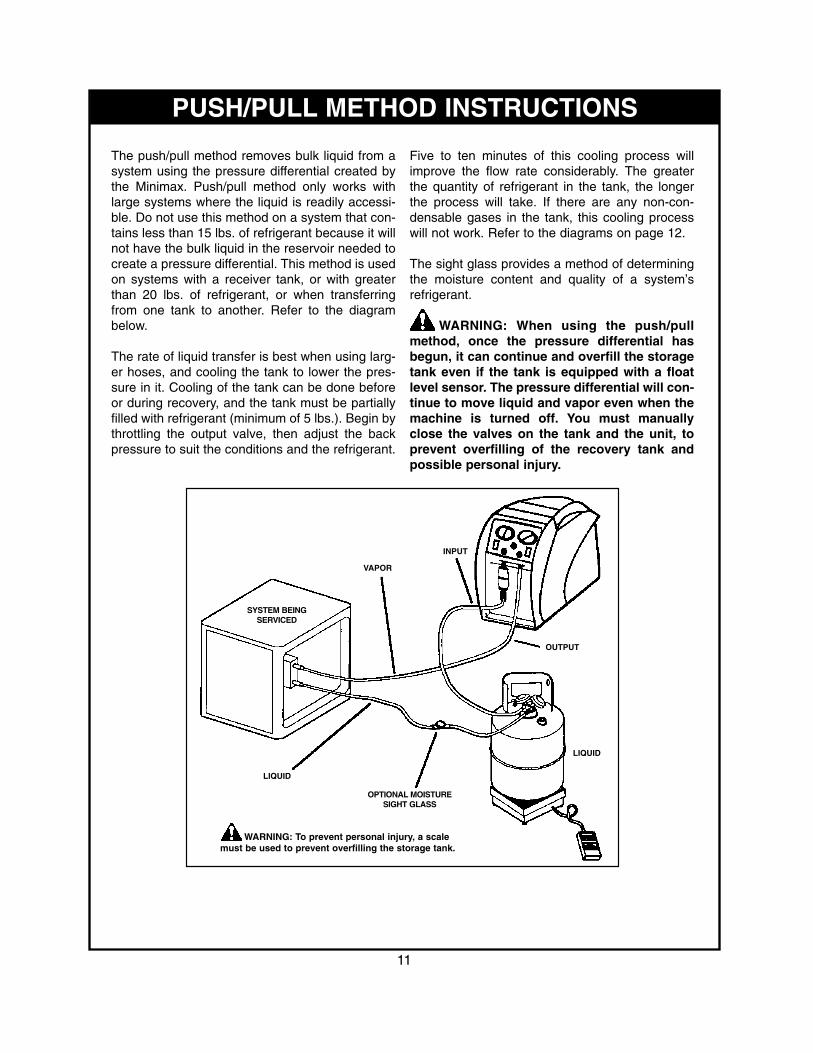
WARNING: To prevent personal injury, a scalemust be used to prevent overfilling the storage tank.
The push/pull method removes bulk liquid from asystem using the pressure differential created bythe Minimax. Push/pull method only works withlarge systems where the liquid is readily accessi-ble. Do not use this method on a system that con-tains less than 15 lbs. of refrigerant because it willnot have the bulk liquid in the reservoir needed tocreate a pressure differential. This method is usedon systems with a receiver tank, or with greaterthan 20 lbs. of refrigerant, or when transferringfrom one tank to another. Refer to the diagrambelow.
The rate of liquid transfer is best when using larg-er hoses, and cooling the tank to lower the pres-sure in it. Cooling of the tank can be done beforeor during recovery, and the tank must be partiallyfilled with refrigerant (minimum of 5 lbs.). Begin bythrottling the output valve, then adjust the backpressure to suit the conditions and the refrigerant.
Five to ten minutes of this cooling process willimprove the flow rate considerably. The greaterthe quantity of refrigerant in the tank, the longerthe process will take. If there are any non-con-densable gases in the tank, this cooling processwill not work. Refer to the diagrams on page 12.
The sight glass provides a method of determiningthe moisture content and quality of a system’srefrigerant.
WARNING: When using the push/pullmethod, once the pressure differential hasbegun, it can continue and overfill the storagetank even if the tank is equipped with a floatlevel sensor. The pressure differential will con-tinue to move liquid and vapor even when themachine is turned off. You must manuallyclose the valves on the tank and the unit, toprevent overfilling of the recovery tank andpossible personal injury.
11
RECOVERY / TANK PRE- ORSUB-COOLING FOR A FIXED HOSE SET-UP
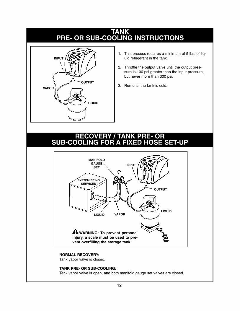
NORMAL RECOVERY:Tank vapor valve is closed.
TANK PRE- OR SUB-COOLING:Tank vapor valve is open, and both manifold gauge set valves are closed.
12
WARNING: To prevent personalinjury, a scale must be used to pre-vent overfilling the storage tank.
LIQUID
OUTPUT
VAPORLIQUID
MANIFOLDGAUGE
SET
SYSTEM BEINGSERVICED
INPUT
TANKPRE- OR SUB-COOLING INSTRUCTIONS
INPUT
OUTPUT
VAPOR
LIQUID
1. This process requires a minimum of 5 lbs. of liq-uid refrigerant in the tank.
2. Throttle the output valve until the output pres-sure is 100 psi greater than the input pressure,but never more than 300 psi.
3. Run until the tank is cold.

REFRIGERANT RECYCLING
Current regulations state that used refrigerantmust not be sold, or used in a different owner’sequipment, unless the refrigerant has been labo-ratory analyzed and found to meet the require-ments of ARI 700 (latest edition).
If the refrigerant is to be used again in the samesystem, it is best to clean it as much as possible.We recommend using the largest, high-acidcapacity filter possible. Place the filter on the suc-tion (inlet side) of the Minimax, and replace themoften.
Some systems do not have an adequate oil sepa-rator installed, so the refrigerant will contain oil asyou recover it. If the refrigerant you are recoveringis not going to be used in the same system and itcontains oil, you will need to separate the oil fromthe refrigerant. This allows you to measure theamount of oil that needs to be charged back intothis system. To do this:
WARNING: Wear safety goggles and pro-tective equipment to prevent burns from acidicoil.1. Begin with a 30 or 50 lb. tank in-line with the
Minimax.2. Connect the system to the liquid port of the
tank.3. From the vapor port of the tank, connect to the
input of the Minimax.4. Connect another tank (for storing refrigerant) to
the output of the Minimax.5. Begin the recovery process.
NOTE: If it's a large amount of liquid refriger-ant, place a band heater around the first tank.
6. When the recovery process is complete, the oilin the first tank can be removed by applying asmall amount of pressure with nitrogen to oneof the ports. The oil will expel from the otherport. Turn the tank upside down if removing theoil through the vapor port.
13
14
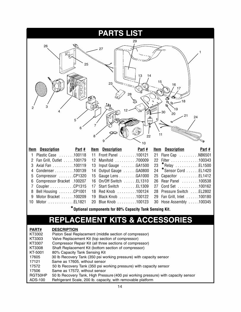
PARTS LIST
REPLACEMENT KITS & ACCESSORIESPART# DESCRIPTIONKT3302 Piston Seal Replacement (middle section of compressor)KT3303 Valve Replacement Kit (top section of compressor)KT3307 Compressor Repair Kit (all three sections of compressor)KT3308 Shaft Replacement Kit (bottom section of compressor)KT-5001 80% Capacity Tank Sensing Kit17605 30 lb Recovery Tank (350 psi working pressure) with capacity sensor 17121 Same as 17605, without sensor17572 50 lb Recovery Tank (350 psi working pressure) with capacity sensor 17506 Same as 17572, without sensorRGT50HP 50 lb Recovery Tank, High Pressure (400 psi working pressure) with capacity sensor ADS-100 Refrigerant Scale, 200 lb. capacity, with removable platform
1
2 34
5
67
89
11
12
13 14
1516
17
18
1920 21
22
23
28
24
25
2627
10
29
30
*Optional components for 80% Capacity Tank Sensing Kit.
1 Plastic Case . . . . . . .1001182 Fan Grill, Outlet . . . . .1001793 Axial Fan . . . . . . . . . .1001194 Condenser . . . . . . . . .1001395 Compressor . . . . . . .CP13206 Compressor Bracket .1002077 Coupler . . . . . . . . . . .CP13158 Bell Housing . . . . . . .CP10019 Motor Bracket . . . . . .100209
10 Motor . . . . . . . . . . . .EL1821
11 Front Panel . . . . . . . .10012112 Manifold . . . . . . . . . .70000913 Input Gauge . . . . . . .GA150014 Output Gauge . . . . . .GA080015 Gauge Lens . . . . . . . .GA100016 On/Off Switch . . . . . .EL131017 Start Switch . . . . . . .EL130918 Red Knob . . . . . . . . .10012419 Black Knob . . . . . . . .10012220 Blue Knob . . . . . . . . .100123
21 Flare Cap . . . . . . . . .NB650122 Filter . . . . . . . . . . . . .10034323 *Relay . . . . . . . . . . .EL150024 *Sensor Cord . . . . . .EL142025 Capacitor . . . . . . . . .EL141226 Rear Panel . . . . . . . .10053827 Cord Set . . . . . . . . . .10016228 Pressure Switch . . . .EL280229 Fan Grill, Inlet . . . . . .10018030 Hose Assembly . . . . .100345
Item Description Part # Item Description Part # Item Description Part #

MINIMAX WIRING DIAGRAM
MINIMAX-KT WIRING DIAGRAMINCLUDING OPTIONAL TANK CAPACITY SENSING CIRCUITRY (KIT: KT-5001)
15
3 PINCONNECTORFOR OPTIONALKT-5001
3 PINCONNECTORFOR OPTIONALKT-5001
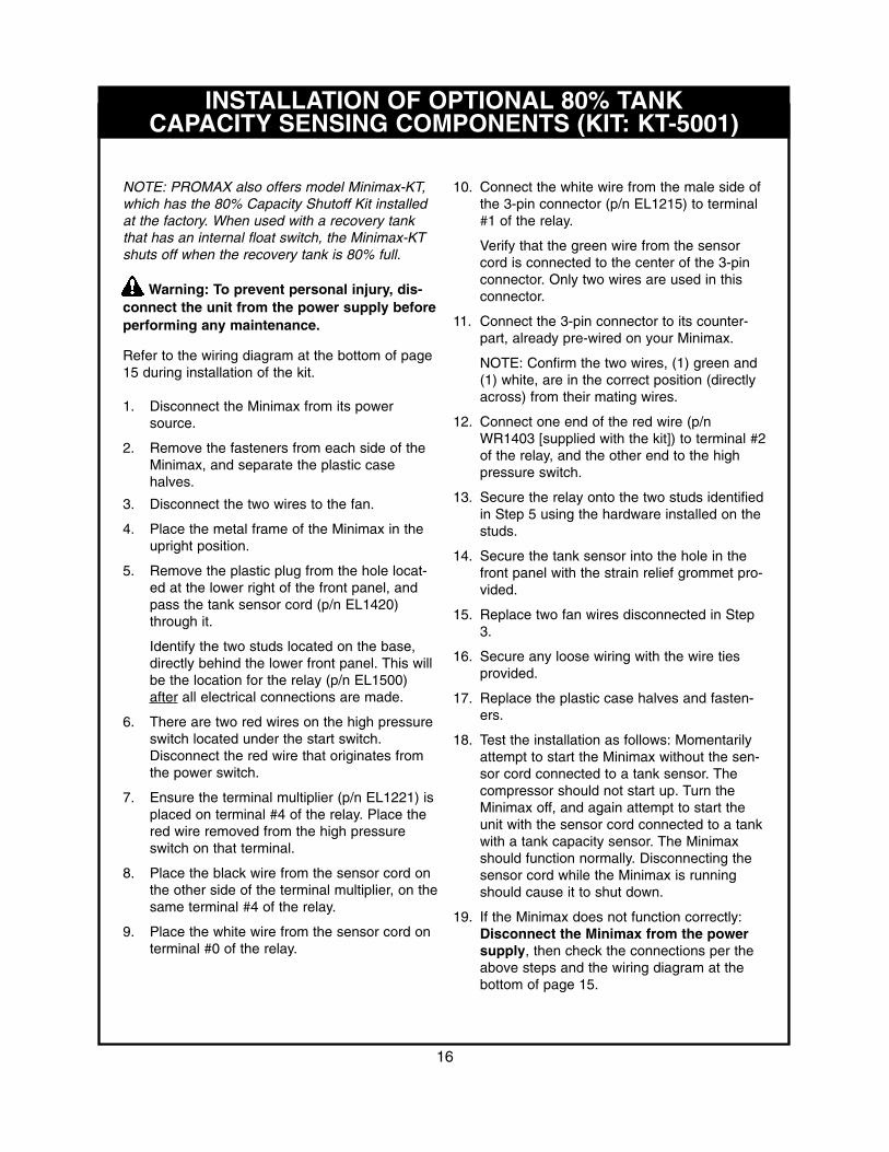
INSTALLATION OF OPTIONAL 80% TANKCAPACITY SENSING COMPONENTS (KIT: KT-5001)
16
NOTE: PROMAX also offers model Minimax-KT,which has the 80% Capacity Shutoff Kit installedat the factory. When used with a recovery tankthat has an internal float switch, the Minimax-KTshuts off when the recovery tank is 80% full.
Warning: To prevent personal injury, dis-connect the unit from the power supply beforeperforming any maintenance.
Refer to the wiring diagram at the bottom of page15 during installation of the kit.
1. Disconnect the Minimax from its powersource.
2. Remove the fasteners from each side of theMinimax, and separate the plastic casehalves.
3. Disconnect the two wires to the fan.
4. Place the metal frame of the Minimax in theupright position.
5. Remove the plastic plug from the hole locat-ed at the lower right of the front panel, andpass the tank sensor cord (p/n EL1420)through it.
Identify the two studs located on the base,directly behind the lower front panel. This willbe the location for the relay (p/n EL1500)after all electrical connections are made.
6. There are two red wires on the high pressureswitch located under the start switch.Disconnect the red wire that originates fromthe power switch.
7. Ensure the terminal multiplier (p/n EL1221) isplaced on terminal #4 of the relay. Place thered wire removed from the high pressureswitch on that terminal.
8. Place the black wire from the sensor cord onthe other side of the terminal multiplier, on thesame terminal #4 of the relay.
9. Place the white wire from the sensor cord onterminal #0 of the relay.
10. Connect the white wire from the male side ofthe 3-pin connector (p/n EL1215) to terminal#1 of the relay.
Verify that the green wire from the sensorcord is connected to the center of the 3-pinconnector. Only two wires are used in thisconnector.
11. Connect the 3-pin connector to its counter-part, already pre-wired on your Minimax.
NOTE: Confirm the two wires, (1) green and(1) white, are in the correct position (directlyacross) from their mating wires.
12. Connect one end of the red wire (p/nWR1403 [supplied with the kit]) to terminal #2of the relay, and the other end to the highpressure switch.
13. Secure the relay onto the two studs identifiedin Step 5 using the hardware installed on thestuds.
14. Secure the tank sensor into the hole in thefront panel with the strain relief grommet pro-vided.
15. Replace two fan wires disconnected in Step3.
16. Secure any loose wiring with the wire tiesprovided.
17. Replace the plastic case halves and fasten-ers.
18. Test the installation as follows: Momentarilyattempt to start the Minimax without the sen-sor cord connected to a tank sensor. Thecompressor should not start up. Turn theMinimax off, and again attempt to start theunit with the sensor cord connected to a tankwith a tank capacity sensor. The Minimaxshould function normally. Disconnecting thesensor cord while the Minimax is runningshould cause it to shut down.
19. If the Minimax does not function correctly:Disconnect the Minimax from the powersupply, then check the connections per theabove steps and the wiring diagram at thebottom of page 15.

17
TROUBLESHOOTING
WARNING: To prevent personal injury and/or equipment dam-age, read and understand all safety information contained inthis manual before servicing the unit.
CONNECT UNITTO 115V
FAN IS RUNNINGWHEN POWER SWITCH
IS IN “ON” POSITION
COMPRESSOR STARTSWHEN START SWITCH
IS PRESSED
UNIT PUMPS INTOHIGH PRESSURE SHUT
OFF
UNIT PULLSINTO A VACUUM
CHECK POWERSUPPLY
IS UNIT IN HIGHPRESSURESHUT OFF?
ARE VALVES OPEN?CHECK
FOR SCHRADERVALVES
ARE THE HOSES TIGHT?
DO YOU HAVE 115V?
IS THE TANKCORD ATTACHED
TO THE TANK?
DOES TANK FLOATSWITCH WORK
PROPERLY?
DOES UNIT PULL AVACUUM WHEN INPUT
VALVE IS CLOSED? CA
LL
PR
OM
AX
FO
R F
UR
TH
ER
AS
SIS
TAN
CE
1-8
00-3
27-5
060
NO NO
NO NO
NO NO NO
NONONO
YES YES
YES YES
YES
YES
YES YES YES
YES YES YES
TROUBLESHOOTING ENDS

ONE-YEAR WARRANTY
MFG #Promax products are warranted to be free from defects in workmanship and materials for a period ofone year from date of purchase.
THE FOLLOWING RESTRICTIONS APPLY:
1. The warranty applies to products in normal use only, as described in the operating manual. Theproduct must also be serviced and maintained as described therein.
2. If the product fails, it will be replaced at the option of SPX Corporation.
3. Warranty service claims are subject to factory inspection for product defect(s). If during the warrantyevaluation it is determined that a filter has not been used, or that the filter was not properly main-tained, or that the machine has been used in any way other than the purpose for which it wasdesigned, SPX reserves the right to void the warranty.
4. All warranty claims must be made within the warranty period. Proof of purchase must be supplied.This warranty is non-transferable.
5. Please note that the warranty does not apply if the product or product part is damaged by accident,mis-use, tampered with or modified in any way.
6. Normal wear items (seals, filters, etc.) are specifically excluded from warranty, unless found byPromax to be defective.
WARRANTY SERVICE
This warranty is given by SPX Corporation.Service under this warranty must be obtained by the following steps:
1. Outside the U.S.A., contact your local Promax Distributor.2. Inside the U.S.A., call 1.800.327.5060 for a return material authorization (RMA) number.
18
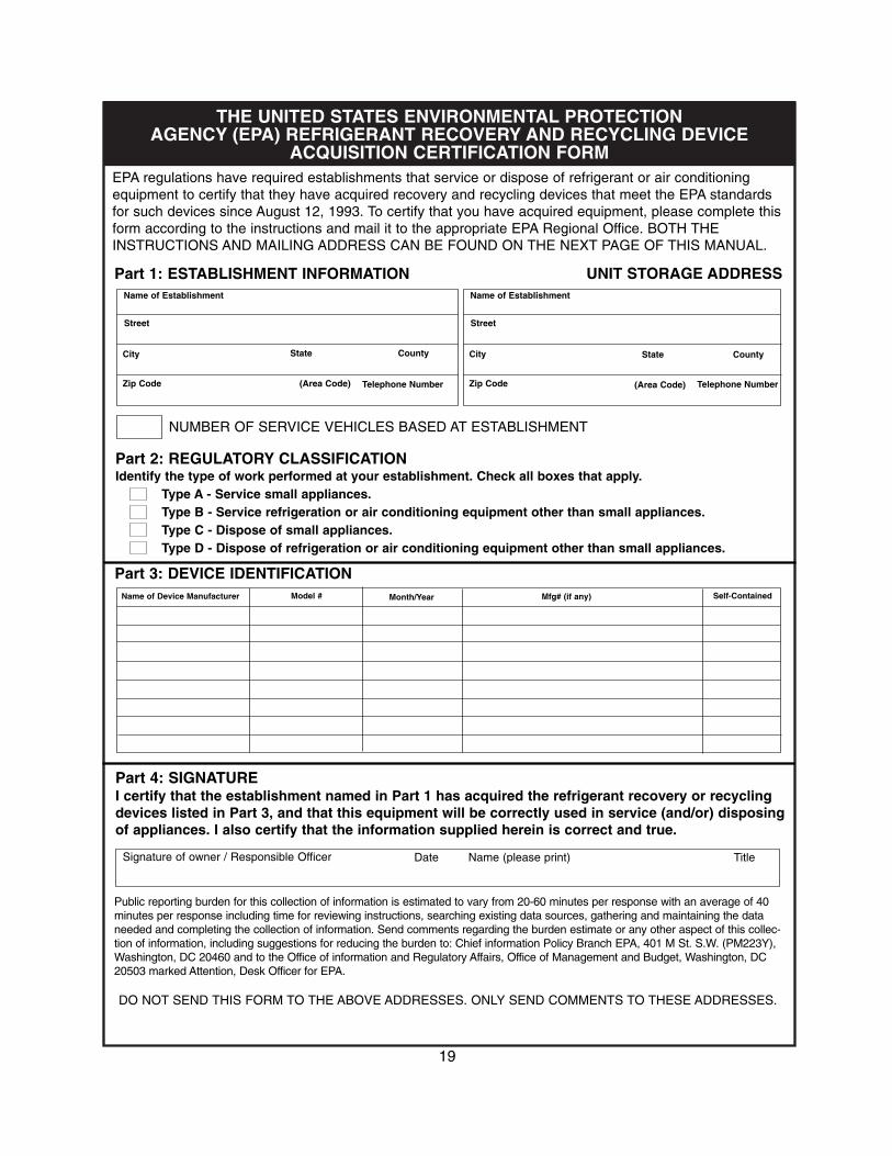
THE UNITED STATES ENVIRONMENTAL PROTECTION AGENCY (EPA) REFRIGERANT RECOVERY AND RECYCLING DEVICE
ACQUISITION CERTIFICATION FORMEPA regulations have required establishments that service or dispose of refrigerant or air conditioningequipment to certify that they have acquired recovery and recycling devices that meet the EPA standardsfor such devices since August 12, 1993. To certify that you have acquired equipment, please complete thisform according to the instructions and mail it to the appropriate EPA Regional Office. BOTH THEINSTRUCTIONS AND MAILING ADDRESS CAN BE FOUND ON THE NEXT PAGE OF THIS MANUAL.
Part 1: ESTABLISHMENT INFORMATION UNIT STORAGE ADDRESSName of Establishment
Street
City
Zip Code
State County
(Area Code) Telephone Number
Name of Establishment
Street
City
Zip Code
State County
(Area Code) Telephone Number
NUMBER OF SERVICE VEHICLES BASED AT ESTABLISHMENT
Part 2: REGULATORY CLASSIFICATIONIdentify the type of work performed at your establishment. Check all boxes that apply.
Type A - Service small appliances.Type B - Service refrigeration or air conditioning equipment other than small appliances.Type C - Dispose of small appliances.Type D - Dispose of refrigeration or air conditioning equipment other than small appliances.
Part 3: DEVICE IDENTIFICATIONName of Device Manufacturer Model # Month/Year Mfg# (if any) Self-Contained
Part 4: SIGNATUREI certify that the establishment named in Part 1 has acquired the refrigerant recovery or recyclingdevices listed in Part 3, and that this equipment will be correctly used in service (and/or) disposingof appliances. I also certify that the information supplied herein is correct and true.
Signature of owner / Responsible Officer Date Name (please print) Title
Public reporting burden for this collection of information is estimated to vary from 20-60 minutes per response with an average of 40minutes per response including time for reviewing instructions, searching existing data sources, gathering and maintaining the dataneeded and completing the collection of information. Send comments regarding the burden estimate or any other aspect of this collec-tion of information, including suggestions for reducing the burden to: Chief information Policy Branch EPA, 401 M St. S.W. (PM223Y),Washington, DC 20460 and to the Office of information and Regulatory Affairs, Office of Management and Budget, Washington, DC20503 marked Attention, Desk Officer for EPA.
DO NOT SEND THIS FORM TO THE ABOVE ADDRESSES. ONLY SEND COMMENTS TO THESE ADDRESSES.
19

INSTRUCTIONS EPA REGIONAL OFFICES
20
Part 1. Please provide the name, address and telephonenumber of the establishment where the refrigerant recov-ery or recycling device(s) is (are) located. Complete oneform for each location. State the number of vehiclesbased at this location that are used to transport techni-cians and equipment to and from service sites.
Part 2. Check the appropriate box for the type of workperformed by technicians who are employees of theestablishment. The term "small appliance" refers to any ofthe following products that are fully manufactured,charged and hermetically sealed in a factory with five orless pounds of refrigerant:
Refrigerators or freezers designed for home use, roomair conditioners (including window air conditioners andpackaged thermal air conditioners), packaged thermalheat pumps, dehumidifiers, under-the-counter ice mak-ers, vending machines, and drinking water coolers.
Part 3. For each recovery or recycling device acquired,please list the name of the manufacturer of the device,and (if applicable) its model number and manufacturernumber. If more than 8 devices have been acquired, fillout an additional form and attach it to the first one.
Recovery devices that are self-contained should be listedfirst, and should be identified by checking the box in thelast column on the right. A self-contained device is onethat uses its own pump or compressor to remove refriger-ant from refrigeration or air conditioning equipment. Onthe other hand, system dependent recovery devices relysolely upon the compressor in the refrigeration or air con-ditioning equipment and/or upon the pressure of therefrigerant inside the equipment to remove the refrigerant.
If the establishment has been listed as Type B and/orType D in Part 2, then the first device listed in Part 3 mustbe a self-contained device and identified as such bychecking the box in the last column on the right.
If any of the devices are homemade, they should be iden-tified by writing "homemade" in the column provided forlisting the name of the device manufacturer. Homemadedevices can be certified for establishments that are listedas Type A or Type B in Part 2 until six months after prom-ulgation of the rule. If a Type C or Type D establishmentis certifying equipment six months after promulgation ofthe rule, then it must not use these devices for servicejobs classified as Type A or Type B.
Part 4. This form must be signed by either the owner ofthe establishment or another responsible officer. The per-son who signs is certifying that the establishment hasacquired the equipment, that the establishment is comply-ing with Section 608 regulations, and that the informationprovided is true and correct.
Send your form to the EPA office listed under the state orterritory in which your establishment is located.
CONNECTICUT, MAINE, MASSACHUSETTS, NEWHAMPSHIRE, RHODE ISLAND, VERMONT CAA 608 Enforcement Contact: EPA Region 1.Mail Code APC, One Congress Street, John F. KennedyFederal Building, Boston, MA 02203-0001Phone: (617) 565-3420
NEW YORK, NEW JERSEY, PUERTO RICO, VIRGINISLANDS CAA 608 Enforcement Contact: EPA Region 2. 290 Broadway, New York, NY 10007-1866Phone: (212) 637-3000
DELAWARE, DISTRICT OF COLOMBIA, MARYLAND,PENNSYLVANIA, VIRGINIA, WEST VIRGINIACAA 608 Enforcement Contact: EPA Region 3. Mail Code3AT21, 841 Chestnut Street, Philadelphia, PA 19107Phone: (800) 438-2474
ALABAMA, FLORIDA, GEORGIA, KENTUCKY, MISSIS-SIPPI, NORTH CAROLINA, SOUTH CAROLINA, TEN-NESSEECAA 608 Enforcement Contact: EPA Region 4. Mail CodeAPT-AE, 61 Forsyth Street, SW, Atlanta, GA 30303Phone: (404) 562-9900
ILLINOIS, INDIANA, MICHIGAN, MINNESOTA, OHIO,WISCONSIN CAA 608 Enforcement Contact: EPA Region 5. Mail CodeAT18J, 77 West Jackson Blvd., Chicago, IL 60604-3507Phone: (312) 353-2000
ARKANSAS, LOUISIANA, NEW MEXICO, OKLAHOMA,TEXASCAA 608 Enforcement Contact: EPA Region 6. Mail Code6T-EC, Fountain Place, 12th Floor, Suite 12001445 Ross Avenue, Dallas, TX 75202-2733Phone: (214) 665-2200
IOWA, KANSAS, MISSOURI, NEBRASKACAA 608 Enforcement Contact: EPA Region 7. Mail CodeARTX/ARBR, 726 Minnesota Ave, Kansas City, KS 66101Phone: (913) 551-7003
COLORADO, MONTANA, NORTH DAKOTA, SOUTHDAKOTA, UTAH, WYOMING CAA 608 Enforcement Contact: EPA Region 8. Mail Code8AT-AP, 999 18th Street, Suite 500Denver, CO 80202-2466Phone: (303) 312-6312
AMERICAN SAMOA, ARIZONA, CALIFORNIA, GUAM,HAWAII, NEVADACAA 608 Enforcement Contact: EPA Region 9. Mail CodeA-3, 75 Hawthorne Street, San Francisco, CA 94105Phone: (415) 744-1305
ALASKA, IDAHO, OREGON, WASHINGTONCAA 608 Enforcement Contact: EPA Region 10.Mail Code AT-082, 1200 Sixth Ave.Seattle, WA 98101Phone: (206) 553-1200
100116 Rev DDesigned & Engineered in the USAManufactured in China
655 Eisenhower DriveOwatonna, MN 55060
Toll Free: (800) 327-5060Fax: (866) 287-7222
www.PromaxRecovery.com
TM