user's manual for - universal programmers | production … · · 2014-09-09user's...
TRANSCRIPT

User's Manual for
BeeHive8S Fast universal 8x 48-pindrive Stand-Alone concurrent multiprogramming system
ELNEC s.r.o. Presov, Slovakia
March 2009

ELNEC s.r.o.
This document is copyrighted by ELNEC s.r.o., Presov, Slovakia. All rights reserved. This document or any part of it may not be copied, reproduced or translated in any form or in any way without the prior written permission of ELNEC s.r.o. The control program is copyright ELNEC s.r.o., Presov, Slovakia. The control program or any part of it may not be analyzed, disassembled or modified in any form, on any medium, for any purpose. Information provided in this manual is intended to be accurate at the moment of release, but we continuously improve all our products. Please consult manual on www.elnec.com. ELNEC s.r.o. assumes no responsibility for misuse of this manual. ELNEC s.r.o. reserves the right to make changes or improvements to the product described in this manual at any time without notice. This manual contains names of companies, software products, etc., which may be trademarks of their respective owners. ELNEC s.r.o. respects those trademarks.
COPYRIGHT © 1997 - 2009 ELNEC s.r.o.
ZLI-0307B
2
ELNEC s.r.o.
Table of contents
Introduction .............................................................................................................................. 4 BeeHive8S elements ............................................................................................................. 7 Manipulation with the programmed device ............................................................................ 8 In-system serial programming by BeeHive8S........................................................................ 8 Selftest and calibration check ................................................................................................ 9 Technical specification......................................................................................................... 11
Programming a device........................................................................................................... 16 Engineering mode................................................................................................................ 16 Production mode.................................................................................................................. 20
Software .................................................................................................................................. 23 Detailed description of Graphics user interface with touch screen...................................... 23 Administration of build in PC................................................................................................ 39
Troubleshooting and warranty.............................................................................................. 43 Troubleshooting ................................................................................................................... 43 If you have an unsupported target device............................................................................ 44 Maintenance ........................................................................................................................ 44 Warranty terms .................................................................................................................... 45
Please, download actual version of manual from ELNEC WEB site (www.elnec.com), if current one
will be out of date.
Conventions used in the manual References to the control program functions are in bold, e.g. Load, File, Device, etc. References to control keys are written in brackets <>, e.g. <F1>.
Terminology used in the manual: Device any kind of programmable integrated circuits or programmable
devices ZIF socket Zero Insertion Force socket used for insertion of target device Buffer part of memory or disk, used for temporary data storage USB port type of PC port HEX data format format of data file, which may be read with standard text viewers;
e.g. byte 5AH is stored as characters '5' and 'A', which mean bytes 35H and 41H. One line of this HEX file (one record) contains start address and data bytes. All records are secured with checksum.
3

ELNEC s.r.o.
Introduction
BeeHive8S is extremely fast universal 8x 48-pindrive Stand-Alone concurrent multiprogramming system designed for high volume production programming with minimal operator effort. The chips are programmed at near theoretical maximum programming speed. Block scheme of BeeHive8S
site 1 site 8
Windows XP Embeddeddriven
high performance PCgraphics control unit with touch screen
external displaykeyboardmouse
site 2 site 3 site 4 site 5 site 6 site 7
optional
BeeHive8S consists of eight independent isolated universal programming modules, based on the BeeProg+ programmer hardware. Therefore BeeHive8S sockets can run asynchronously (concurrent programming mode). Each programming module starts programming at the moment the chip is detected to be inserted in the socket properly - independently of the status of other programming modules. This results in seven programming modules working while you replace the programmed chip in the eighth. Graphical control unit with touch screen provides basic control and easy monitoring of the programming flow. Modular construction of hardware - the programming modules work independently - allows for continuing operation when a part of the circuit becomes inoperable. It also makes service quick and easy. Hands-free operation: asynchronous and concurrent operation allows a chip to begin programming immediately upon insertion of a chip. The operator merely removes the finished chip and inserts a new chip. Operator training is therefore minimized. BeeHive8S supports all kinds and types of silicon technology found in today’s and tomorrows programmable devices without family specific modules. You can be sure that new device support requires the software to be updated and (if necessary) simple
4

ELNEC s.r.o.
package converter (programming adapter), therefore the ownership costs are minimized. Using built-in in-circuit serial programming (ISP) connector, the programmer is able to program ISP capable chips in circuit. BeeHive8S provides very competitive price coupled with excellent hardware design for reliable programming. It has probably best "value for money" programmer in this class. BeeHive8S provides very fast programming due to high-speed FPGA driven hardware and execution of time-critical routines inside of the programmer. At least programming speed is faster than competitors in this category, for many chips it is much faster than most competitors. As a result, when used in production this programmer waits for an operator, and not the other way round. BeeHive8S provides the two banana jacks, one for ESD wrist strap connection for easy-to-implement ESD protection and the second one for connection to ground. FPGA based totally reconfigurable 48 powerful TTL pindrivers provide H/L/pull_up/pull_down and read capability for each pin. Advanced pindrivers incorporate high-quality high-speed circuitry to deliver signals without overshoot or ground bounce for all supported devices. Pin drivers operate down to 1.8V so you'll be ready to program the full range of today's advanced low-voltage devices. BeeHive8S performs on each programming module device insertion test (wrong or backward position) and contact check (poor contact pin-to-socket) before it programs each device. These capabilities, supported by overcurrent protection and signature-byte check help prevent chip damage due to operator error. BeeHive8S has the selftest capability, which allows the diagnostic part of software to thoroughly check the health of the each programming module. BeeHive8S has a built-in protection circuit for eliminating the damage of programmer and/or programmed device due to environment or operator failure. All ZIF socket pins of BeeHive8S programmer are protected against ESD up to 15kV. BeeHive8S performs programming verification at the marginal level of supply voltage, which, obviously, improves programming yield, and guarantees long data retention. Various socket converters are available to handle devices in PLCC, SOIC, PSOP, SSOP, TSOP, TSSOP, TQFP, QFN (MLF), SDIP, BGA and other packages. It is important to remember that in most cases new devices require only a software update because the BeeHive8S is based on the truly universal (BeeProg+) programmer. With our prompt service you can have new device added to the list of supported devices within hours! See AlgOR (Algorithm On Request) service for details. Advanced design of the BeeHive8S Stand-Alone multiprogramming system, including protective circuits, original brand components, and careful manufacturing and long burning-in periods allows us to provide a three-year warranty on parts and labor for the programmer (limited 25 000-cycle warranty on ZIF sockets). Although we take as much care as possible to integrate high quality components for the built-in computer, we can't
5

ELNEC s.r.o.
provide the same level warranty as we get from the suppliers of computer parts. Therefore it is a limited warranty of one year for all computer parts such as motherboard, CPU, HD, etc. This warranty terms are valid for customers, who purchase a programmer directly from Elnec company. The warranty conditions of Elnec sellers may differ depending on the target country law system or Elnec seller’s warranty policy. Free additional services: • free lifetime software update via Web site.
Free software updates are available from our Internet address www.elnec.com.
• Online technical support is available within promised 24 hours time limit or you may call us during business hours from Monday through Friday 8:30 to 17:30 (CET).
• Keep-Current is a service by which ELNEC ships to you the latest version of the control program for programmer and the updated user documentation. A Keep-Current service is your hassle-free guarantee that you always have access to the latest software and documentation, at minimal cost.
• AlgOR (Algorithm On Request) service allows you to receive from ELNEC software support for programming devices not yet available in the current device list.
6

ELNEC s.r.o.
BeeHive8S elements 1) 48 pin ZIF socket 2) work result LEDs 3) power/sleep LED of site 4) YES! Button 5) ISP connector 6) graphical control unit with touch screen 7) fan's grid
8) temperature controlled fans 9) banana jack for connection to ground 10) banana jack for ESD wrist straps connection 11) Windows XP Embedded serial number sticker
7

ELNEC s.r.o.
12) PC connectors – e.g. for display, keyboard, mouse… 13) power switch 14) power supply connector 15) Soft power ON/OFF button
Manipulation with the programmed device After the selection of desired device for your work, you can insert it into the open ZIF socket (lever is up) and close socket (lever is down). The correct orientation of the
IF socket on the programmer e socket when the BUSY LED
ectronics protect the target device and the programmer failure. due to
incorrect, user-selected programming parameters. Target device may not be destroyed
In-system serial programming by BeeHive8S
ISP
ction about ISP see section Common
Description of ISP connector
device in ZIF socket is shown on the picture near the Zmed device must be removed from thcover. The program
is off. Note: Programmer protection elitself against either short or long-term power failures and, partly, against a PCHowever, it is not possible to guarantee the integrity of the target device
by forced interruption of the control program (turn off programmer), but the content of programmed cells may remains undefined. Don't unplug the target device from the ZIF socket during work with device (BUSY LED on).
Optimized advanced pindrivers deliver programming performance without overshoot or ground bounce for all device technologies. Pin drivers operate down to 1.8V so you'll be ready to program the full range of today's advanced low- voltage devices. The ISP programming solution performs programming verification at the marginal level of supply voltage, which, obviously, improves programming yield, and guarantees long data retention. The ISP programming solution provides also the power supply for the target system.
This ISP programming solution provides very competitive price but excellent hardware design for reliable programming.
he software provides full information for ISP implementation: Description ofTconnector pins for currently selected chip, recommended target design around in-circuit programmed chip and other relevant information.
or general definition, recommendation and direFnotes / ISP please.
1 3 5
2 4 6
7 9
8 10
11 13
12 14
15 17 19
16 18 20
Front view at ISP connector.
8

ELNEC s.r.o.
Specification of ISP connector pins depends on the device which you want to work with.
rogrammer (Pg4uw), menu Device / Device Info g (ISP) option of respective device must be
selected. It is indicated by (ISP) suffix after the name of selected device. These specifications correspond with application notes published by device manufacturers. Application notes can be found on www.elnec.com
You can find it in the control SW for p(Ctrl+F1). Note the ISP programmin
, section Support / Application Notes. Note: Pin no. 1 is signed by t necto s. riangle mark on ISP cable con r
BeeHive8S ISP cable
Warnings: • Use only ISP cable from delivery package. When you use other ISP cable (other
material, length…), programming may become unreliable. • BeeHive8S can supply power to the programmed device (pin 1 of ISP connector)
and the target system (pin 19 and 20 of ISP connector) with some limitations (see Technical specification / ISP connector).
• BeeHive8S applies programming voltage to target device and checks its value (target system can modify programming voltage). If the programming voltage is different from expected, no action with target device will be executed.
d driver Note: H/L/rea
R1H/L driverin programmer pin of ISP
connector
read driverin programmer
R2
PU/PD driverin programmer
R3
R1=180R R2=1k3 R3=22k
Selftest and calibration check Warning: Selftest and calibration check can be run in engineering mode only. This mode is available only when external display, keyboard and mouse are connected to BeeHive8S.
9
ELNEC s.r.o.
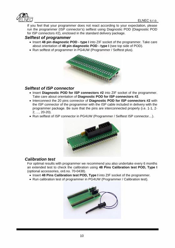
If you feel that y tion, please iagnostic POD (Diagnostic POD y package.
pin diagnostic POD - type I into ZIF socket of the programmer. Take care of POD).
our programmer does not react according to your expectarun the programmer (ISP connector’s) selftest using Dfor ISP connectors #2), enclosed in the standard deliver
Selftest of programmer • Insert 48
about orientation of 48 pin diagnostic POD - type I (see top side • Run selftest of programmer in PG4UW (Programmer / Selftest plus).
Se
• Insert Diagnostic POD for ISP connectors #2 into ZIF socket of the programmer. Take care about orientation of Diagnostic POD for ISP connectors #2.
• Interconnect the 20 pins connector of Diagnostic POD for ISP connectors #2 with the ISP connector of the programmer with the ISP cable included in delivery with the programmer package. Be sure that the pins are interconnected properly (i.e. 1-1, 2-2, ..., 20-20).
• Run selftest of ISP connector in PG4UW (Programmer / Selftest ISP connector…).
lftest of ISP connector
Calibration test
For optimal results with programmer we recommend you also undertake every 6 months an extended test to check the calibration using 48 Pins Calibration test POD, Type I (optional accessories, ord.no. 70-0438). • Insert 48 Pins Calibration test POD, Type I into ZIF socket of the programmer. • Run calibration test of programmer in PG4UW (Programmer / Calibration test).
10

ELNEC s.r.o.
Technical specification Specification (BeeHive8S multiprogramming system)
• 8x universal programming module (8x 48-pin DIL ZIF sockets and 8x ISP connector) • operation result LEDs, LED power • line power input 100-240VAC/60W max. • banana jack for ESD wrist straps connection • banana jack for connection to ground
e of programmer) ystem
S programming module) H
transfer rate PGA based state machine
, VPP1, and VPP2, controllable rise and fall time V/1A
nge 0..26V/1A
er Insertion Force) socket accepts both 300/600 mil devices up to
s H, L, CLK, pull-up, pull-down on all pindriver pins lectable from 1.8 V up to 26V
rrent shutdown, power failure shutdown each pin of socket (IEC1000-4-2: 15kV air, 8kV contact)
n is tested before every programming operation
ISs insertion lock
wn; level H selectable from 1.8V
Specification (PC system insid• Microsoft Windows XP Embedded operation s• PC Intel Core 2 Duo 2.4 GHz • 1024 MB RAM • 160 GB HDD
PECIFICATION (valid for eachARDWARE
Base unit, DACs • USB 2.0 high-speed compatible port, up to 480 Mbit/s
l microprocessor and F• on-board intelligence: powerfurters for VCCP• three D/A conve
• ..8 VCCP range 0• VPP1, VPP2 ra• autocalibration/selftest • selftest capability
Socket, pindriv• 48-pin DIL ZIF (Zero
48-pin • pindrivers: 48 universal • VCCP / VPP1 / VPP2 can be connected to each pin
pin • perfect ground for each• FPGA based TTL driver provide
level se• analog pindriver outputovercu• current limitation,
• ESD protection on• continuity test: each pi
P connector • 20-pin male type with mis• 6 TTL pindrivers, provides H, L, CLK, pull-up, pull-do
ltage including) devices. up to 5V to handle all (low-vo• 1x VCCP voltage (range 2V..7V/100mA) , can be applied to two pins
11
ELNEC s.r.o.
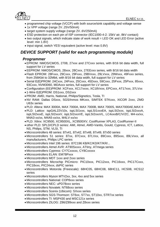
• programmed chip voltage (VCCP) with both source/sink capability and voltage sense
kV contact) , which indicate state of work result = LED OK and LED Error (active
max 0.8V)
DEP
ries, with 8/16 bit data width es,
• : 24Cxxx, 24Fxxx, 25Cxxx, 45Dxxx, 59Cxxx, 25Fxxx, 25Pxxx, 85xxx,
LVxx
rris, National, Philips/Signetics, Tesla, TI
x50 series
•
CS08, HCS12
xx, ST10xx, STR7xx series eries
• Microcontrollers ZILOG: Z86/Z89xxx and Z8xxx series
• 1x VPP voltage (range 2V..25V/50mA) • target system supply voltage (range 2V..6V/250mA) • ESD protection on each pin of ISP connector (IEC1000-4-2: 15kV air, 8• two output signals
level: min 1.8V) • input signal, switch YES! equivalent (active level:
VICE SUPPORT (valid for each programming module) rogrammer • EPROM: NMOS/CMOS, 2708, 27xxx and 27Cxxx series, with 8/16 bit data width, full
support for LV series • EEPROM: NMOS/CMOS, 28xxx, 28Cxxx, 27EExxx se• Flash EPROM: 28Fxxx, 29Cxxx, 29Fxxx, 29BVxxx, 29LVxxx, 29Wxxx, 49Fxxx seri
from 256Kbit to 32Mbit, with 8/16 bit data width, full support for LV series Serial E(E)PROM93Cxxx, NVM3060, MDAxxx series, full support for LV series
• Configuration (EE)PROM: XCFxxx, XC17xxxx, XC18Vxxx, EPCxxx, AT17xxx, 37• 1-Wire E(E)PROM: DS1xxx, DS2xxx • PROM: AMD, Ha• NV RAM: Dallas DSxxx, SGS/Inmos MKxxx, SIMTEK STKxxx, XICOR 2xxx, ZMD
U63x series PLD: Altera: MAX 3000• A, MAX 7000A, MAX 7000B, MAX 7000S, MAX7000AE,MAX II • PLD: Lattice: ispGAL22V10x, ispLSI1xxx, ispLSI1xxxEA, ispLSI2xxx, ispLSI2xxxA,
ispLSI2xxxE, ispLSI2xxxV, ispLSI2xxxVE, ispLSI2xxxVL, LC4xxxB/C/V/ZC, M4-xx/xx, M4A3-xx/xx, M4A5-xx/xx, M4LV-xx/xx
• PLD: Xilinx: XC9500, XC9500XL, XC9500XV, CoolRunner XPLA3, CoolRunner-II • other PLD: SPLD/CPLD series: AMI, Atmel, AMD-Vantis, Gould, Cypress, ICT, Lattice,
NS, Philips, STM, VLSI, TI • Microcontrollers 48 series: 87x41, 87x42, 87x48, 87x49, 87• Microcontrollers 51 series: 87xx, 87Cxxx, 87LVxx, 89Cxxx, 89Sxxx, 89LVxxx, all
manufacturers, Philips LPC series Microcontrolle• rs Intel 196 series: 87C196 KB/KC/KD/KT/KR/... • Microcontrollers Atmel AVR: AT90Sxxxx, ATtiny, ATmega series • Microcontrollers Cypress: CY7Cxxxxx, CY8Cxxxxx Microcontrollers ELAN: EM78Pxxx • Microcontrollers MDT 1xxx and 2xxx series • Microcontrollers Microchip PICmicro: PIC10xxx, PIC12xxx, PIC16xxx, PIC17Cxxx,
PIC18xxx, PIC24xxx, dsPIC series • Microcontrollers Motorola (Freescale): 68HC05, 68HC08, 68HC11, H
series • Microcontrollers Myson MTV2xx, 3xx, 4xx and 5xx series Microcontrollers National: COP8xxx • series • Microcontrollers NEC: uPD78xxx series • Microcontrollers Novatek: NT68xxx series • Xxxx series Microcontrollers Scenix (Ubicom): S• Microcontrollers SGS-Thomson: ST6xx, ST7• Microcontrollers TI: MSP430 and MSC121x s
12

ELNEC s.r.o.
• Microcontrollers other: EM Microelectronic, Fujitsu, Goal Semiconductor, Hitachi, Holtek, Princeton, Macronix, Winbond, Infineon(Siemens), NEC, Samsung, Toshiba, ...
• upported devices see actual Device list at www.elnec.comNotes: For all s
P series, serial data
xxx, ATtiny, ATmega series
es 12xxx, PIC16xxx, PIC17xxx,
•CS08, HCS12
eries, 89xxx series
• AG and BSL series), MSC12xxx series ispLSI2xxxV,
/xx, M4LV-xx/xx, M4A3-xx/xx, M4A5-xx/xx,
• XV, CoolRunner XPLA3, CoolRunner-II
F see actual Device list at www.elnec.com
rogrammer, through ISP connector • Serial E(E)PROM: IIC series, MW series, SPI series, KEELOQ
Flash, PLD configuration memories • Microcontrollers Atmel: AT89Sxxx, AT90Sx• Microcontrollers Cypress: CY8C2xxxx • Microcontrollers Elan: EM78Pxxx, EM6xxx series • Microcontrollers EM Microelectronic: 4 and 8 bit seri• Microcontrollers Microchip PICmicro: PIC10xxx, PIC
PIC18xxx, PIC24xxx, dsPIC series Microcontrollers Motorola/Freescale: HC11 series, HC908 series (both 5-wire, All-wire), H
• Microcontrollers NEC: uPD7xxx series • Microcontrollers Philips: LPC2xxx series, LPC s• Microcontrollers Scenix (Ubicom): SXxxx series Microcontrollers TI: MSP430 (both JT• PLD: Lattice: ispGAL22xV10x, ispLSI1xxxEA, ispLSI2xxxE,
ispLSI2xxxVE, ispLSI2xxxVL, M4-xxLC4xxxB/C/V/ZC
• Various PLD (also by JAM player/JTAG support): • Altera: MAX 3000A, MAX 7000A, MAX 7000B, MAX 7000S, MAX 9000, MAX II Xilinx: XC9500, XC9500XL, XC9500
Notes: or all supported devices .
Pa
with universal adapters
PrDevic Time
ckage support • support all devices in DIP with default socket • package support includes DIP, SDIP, PLCC, JLCC, SOIC, SOP, PSOP, SSOP,
TSOP, TSOPII, TSSOP, QFP, PQFP, TQFP, VQFP, QFN (MLF), SON, BGA, EBGA, FBGA, VFBGA, UBGA, FTBGA, LAP, CSP, SCSP etc.
• support devices in non-DIP packages up to 48 pins• programmer is compatible with third-party adapters for non-DIP support
ogramming speed e Size [bits] Operation
M50F 100000Hx8 (8 Mega) programming and verify 22 sec W080 (parallel Flash) M 400000Hx16 (64 Mega) programming and verify 57 sec X28F640C3BT (parallel Flash) K9F1G08U0M (par sh) 8400000Hx8 (1 Giga) programming and verify 229 sec allel NAND FlaAT45 ga) programming and verify 36 sec D081 (serial Flash) 108000Hx8 (16 MeAT89C51RD2 (microcontroller) 10000Hx8 programming and verify 15 sec PIC18F452 (microcontroller) 4000Hx16 programming and verify 4 sec
C
gramming e non-
blank data is programmed or are they use data with only a few 0 bits (FE, EF, etc.).
onditions: PG4UW version 2.39a Notes:
pro• It is important to know, we always use random number patterns for speed tests. Some of our competitors use a "sparse" pattern, where only som
13

ELNEC s.r.o.
This deceptive approachplan to compare, ask alw
can "decrease" programming times considerably. If you ays which pattern they use.
The programming speed de e PC speed only slightly.
y manufacture d ware re available y s,
ern and version of software is available for y chip su vailable nearly same day.
Devi• s
nt of part name based selection of EPROM/Flash EPROM read, verify
SD-71 compressed binary variation of SVF files
st, reverse insertion check
• mode (automatic start immediately after device insertion)
erialization modes (more types of incremental modes, from-file data, custom
mode
Buffer operations
lit ••
File load/sa•• a entification/recognition
• pends on th
SOFTWARE • Algorithms: onl r approved or certifie algorithms are used. • Algorithm updates: soft updates a regularly, approx. ever 4 week
free of charge (Int et down Demhighly priorit pport and/or bugs fixes. A
load). On
• Main features: revision history, session logging, on-line help, device and algorithm information
ce operations tandard:
• intelligent device selection by device type, manufacturer or fragme• automatic ID-• blank check, • program • erase • configuration and security bit program • illegal bit test • checksum • interpret the Jam Standard Test and Programming Language (STAPL), JEDEC
standard JE• interpret the VME files
• security • insertion te• contact check • ID byte check special • production• lots of s
generator mode) • statistics • count-down
• view/edit, •
find/replace fill/copy, move, byte swap, word/dword sp
word) checksum (byte, print
ve no download time because programmer is PC controlled
utomatic file type id
14
ELNEC s.r.o.
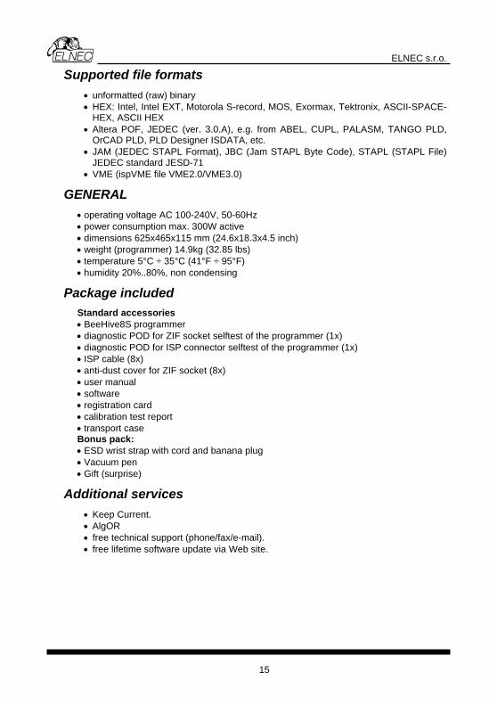
Supported file formats ry
OS, Exormax, Tektronix, ASCII-SPACE-
a POF, JEDEC (ver. 3.0.A), e.g. from ABEL, CUPL, PALASM, TANGO PLD, D Designer ISDATA, etc. TAPL Format), JBC (Jam STAPL Byte Code), STAPL (STAPL File)
• 0V, 50-60Hz ••• ••
Pacessories
programmer programmer (1x)
f the programmer (1x)
and banana plug
Adnt.
rt (phone/fax/e-mail). ate via Web site.
• unformatted (raw) bina• HEX: Intel, Intel EXT, Motorola S-record, M
HEX, ASCII HEX • Alter
OrCAD PLD, PL• JAM (JEDEC S
JEDEC standard JESD-71 • VME (ispVME file VME2.0/VME3.0)
GENERAL operating voltage AC 100-24 power consumption max. 300W active dimensions 625x465x115 mm (24.6x18.3x4.5 inch)
eight (programmerw ) 14.9kg (32.85 lbs) temperature 5°C ÷ 35°C (41°F ÷ 95°F) humidity 20%..80%, non condensing
age included kStandard acc• BeeHive8S • diagnostic POD for ZIF socket selftest of the• st o diagnostic POD for ISP connector selfte• ISP cable (8x) • anti-dust cover for ZIF socket (8x) • user manual • software • registration card • calibration test report • transport case Bonus pack: • ESD wrist strap with cord• Vacuum pen • Gift (surprise)
ditional services • rre Keep Cu• AlgOR • free technical suppo
oftware upd• free lifetime s
15

ELNEC s.r.o.
Programmi
BeeHive8S can operate in two modes:
Engineering mode for creating a project Production mode for mass production
Engineering mode Warning: This mode is available only when external display, keyboard and mouse are connected to BeeHive8S. To switch to Engineering mode use File / Switch to Engineering mode. This part of the software is focused on the quick and easy preparation of the project file for use in the production mode of the control software. Each programming module is driven by an easy-to-use control program with pull-down menu, hot keys and on-line help. Selecting of the device is performed by its class, by manufacturer or simply by typing a fragment of vendor name and/or part number. It is the same time proven software, as is used for all other Elnec single-site programmers. Engineers can use all properties of this software and can make a project for mass production. Standard device-related commands (read, blank check, program, verify, erase) are boosted by some test functions (insertion test, connection check, signature-byte check), and some special functions (autoincrement, production mode - start immediately after insertion of chip into socket). All known data formats are supported. Automatic file format detection and conversion are done during loading of file. It is possible to use Jam files (JEDEC standard JESD-71) and VME files The rich-featured auto-increment function enables one to assign individual serial numbers to each programmed device - or simply increments a serial number, or the function enables one to read serial numbers or any programmed device identification signatures from a user created file. The software also provides a lot of information about programmed device. As an example, the drawings of all available packages, explanation of chip labeling (the meaning of prefixes and suffixes on the chips).
ng a device
16

ELNEC s.r.o.
M
ogrammer.
ake a project 1. Connect external display, keyboard and mouse to PC connectors on back side of
programmer. Turn on pr
2. Run the control program: double click on icon. 3. Find BeeHive8S Site (programmer): <Ctrl+F> or right click on panel
Programmer
17

ELNEC s.r.o.
Select BeeHive8S, Site and then click on “Connect” button.
4. Select site.
Select desired BeeHive8S Site# and then click on “OK” button
5. Select device: click on icon and select desired device
6. Load data into buffer from file: click on icon. 7. Set Device operation options
18
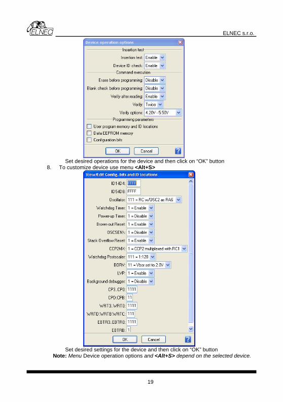
ELNEC s.r.o.
Set desired operations for the device and then click on “OK” button
8. To customize device use menu <Alt+S>
Set desired settings for the device and en click th on “OK” button
tions and <Alt+S> depend on the selected device. Note: Menu Device operation op
19

ELNEC s.r.o.
9. Save project: click on icon and select destination folder, write a description of project etc.
You can make a project on other ELNEC programmers (BeeProg+…) too. For more details see Help for PG4UW (single site driver) and “User manual for all ELNEC programmers”. The latest manual may be found at www.elnec.com part download.
Production mode There are two modes: Mode A: without external display, keyboard and mouse connected to BeeHive8S.
Programming control is only via build in display with touch screen. Mode B: with external display, keyboard and mouse eeHive8S.
ay. Warning: External display, keyboard and mouse not needed in this mode. This part of the software is focused on the easy monitoring of high-volume production operations via graphical control unit with touch screen. The user can control the following basic operations: • load project file • connect/disconnect programmer sites • select desired device master operation (blank check, verify, program, erase) • start/stop device operation on connected programmer sites • set some advanced options to customize available settings, for example Automatic
YES! Function • create Job report • create Problem report • copy project file(s) from external drive (for example from network drive, USB key
etc.) to the standalone's local [Projects] folder • see the progress of device operation, including statistics information, serialization...
Step by step instruction Starting Stand-Alone multiprogramming system 1. Check if the power switch placed at back side of programmer, near power supply
connector is on position '0'. 2. Plug the power cord in to the programmer power supply connector and turn on
the programmer by the power switch placed at back side of programmer. If programmer not starts (cooling fans not start) please, push the “Soft power ON/OFF” button on back side, bellow banana jacks.
connected to BProgramming control is via Pg4uwMC displayed on external displ
20

ELNEC s.r.o.
3. When the built-in computer is turned on the operating system will start booting-
4. operating system can take some time normally this time is shorter
wMC control
on on “Welcome” screen to continue. The main screen with t.
tand-Alone multiprogramming system, or when error message “Programmer Sites not found” is displayed, then programmer
reinitialized by action “Search for Programmers...” available in mer / Search for Programmers...”.
programage will be
ds or more and start “No Programmers found”, please
S er sites hidden control application Pg4uw.
menu
main screen. numbered from #1 to #8 in direction of physical placement
ection is “Ready” or “No project file is loaded“ user le from menu File / Load project.
Selec16. Use menu “Device / Predefined operation“ to select device Master operation.
Following Master operations are available:
up, cooling fans should start to work, and “Wait please” screen should be displayed on graphical control unit. Starting of the than 1 minute.
5. After the operating system has successfully started, the Pg4uprogram will start automatically. When the Pg4uwMC is ready to work the “Welcome” screen is displayed on graphical control unit.
6. Click the OK buttmenus and Status panel should appear on graphical control uni
Checking if the sites are ready to be connected 7. When first starting S
software must bemenu “Program
8. In dialog Search for Programmers use button “Search” to search for present programmer sites. The result of search will be displayed in table Search results in Search dialog. When programmer sites are successfully found, then programmer type and its serial number is show in the table Search result. Detected
mer can be accepted by pressing/touching Accept. If no complete programmer was found, then “No Programmers found” messdisplayed in table Search results and button Accept will be disabled.
9. If search result is “No Programmers found”, please try to turn off Stand-Alone programmer, by menu “File / Shut down computer”, turn off the power button on the back Side of programmer, wait for 15 seconprogrammer again. If the search result is stillrefer to troubleshooting documentation.
tarting programm10. Each programmer site is uses its own 11. To start the hidden applications of control programmer sites, use
“Programmer / Connect Sites”. 12. The “Connecting sites“ indicator is displayed during connection of sites.
Additional information about site connection progress is displayed for each site in panel Status on
13. Programmer sites areof programmer sites from left to right.
14. When connection process of programmer sites is complete, indicator “Connecting Sites” will be hidden. Panel Status will contain information about each site.
Loading project file 15. When site status after conn
can begin the Load project operation accessibThe project file can be loaded from default directory [Projects] or from any other location, for example from USB key. For more details about Load project, refer to the chapter “Menu File“ and Load project. When Load project operation is successfully done for all Sites, the “Ready“ status must be displayed in panel Status on touch screen for all connected Sites. If there are some Sites with different status, use troubleshooting documentation to resolve the problem. tion of predefined device operation
21

ELNEC s.r.o.
Blank check Verify Program Erase For more details about predefined device operations, see chapter Menu
Inser17. <operation> button on
un will be “Run
18. Selected device operation including suboperations that are part of predefined
You exam
Device / Predefined operation. tion of devices in programmer sockets and start device operations Insert devices into programmer sockets and press Run touch screen. <operation> means predefined operation, for example when predefined operation is “Program device“, the caption of button RProgram“.
device operation will start. Progress of operations is displayed in panel status for each programmer site. can use some special features of Stand-Alone multiprogramming system, for ple Count down or Statistics.
22

ELNEC s.r.o.
Softw
Detailewith touch screen
Wait p
are
d description of Graphics user interface
lease screen
Wait please screen is displayed on standalone's built-in LCD screen as the first screen after turning-on power. The screen is shown during booting up of operating system and starting of standalone control software Pg4uwMC.
Welcome screen (About screen)
Welcome screen is displayed on Stand-Alone build-in LCD screen after successful starting of standalone control software. The screen can also be displayed by using menu command Help / About more information see Help / About. Welcome screen can be closed by clicking on button OK.
23

ELNEC s.r.o.
LCD main screen
Main screen consists of following parts: • Menu / File Device Programmer Options Help | • Table with information about programmer sites (site and serialization status) • Panel Next serial value • Panel Statistics • Recently selected device name • Recent project name • Checksum of data stored in data buffer for currently selected device • Run button... ( … can be operation name, for example Program, Verify, Erase) • Stop button
Menu / File Device Programmer Options Help | Each menu item represents one menu command. For detailed information about menu commands, refer to menu commands description chapter.
status of programmer sites and serialization is not used, the Serialization
yed in the Status displayed. Following are typical values:
• Ready means the programmer site is connected and ready to start any operation
• Present special status of connected Site, means the site is connected but it is also not selected (checked in dialog Select Sites). User selected device or project operations will not run on (unselected) Sites. User can set Site selection in dialog 'Select Sites' accessible by menu command Programmer / Select Enabled Sites.
• No project file is loaded means the Site is successfully connected but no project file is loaded. It also means that no device is selected. The recommended action is “Load project“.
• other text describes current status of Site(s), for example:
'Please insert a new device into socket'
Table with information about programmer sites (site and serialization status) Table contains key information about current serialization information for each Site. Ifolumn remains empty. Sites that are not connected, have '–' displac
column. Connected Sites have their Status
'Loading data from disk to buffer' 'Programming device... 85% 'Programming device... OK
24

ELNEC s.r.o.
Next serial value When serialization is active, the panel displays current serialization mode and serialization number or label that will be used for next device programmed. Recent serial numbers used for each device are displayed in table Site and serialization status in column Serialization. Statistics Panel contains information about the number of device operations processed and actual count down status. For more details see Statistics dialog (menu Options / Statistics). Recently selected Device name Manufacturer and name of recently selected devices.
C B name, for example Program, Verify, Erase) C ted device operation for all connected programmer s grammer site. But
vice operation on all
M
hich
Recent Project name Currently loaded project file name.
hecksum of data stored in data buffer for currently selected device.
u ton Run... ( … can be operation start selec
tlick on button Run... willites. Button can be used when no device operation is running on any pro
ton Stop C ill stop executing of currently running deconnected programmer sites.
lick on button Stop w
enu File ile / Load project F
This menu command opens dialog 'Load project', where user can choose, from wlocation the project file has to be loaded and load selected project.
available: T o options are 1. Load project fro [P2. Load project fro an
w
m rojects] folder... m other location...
25

ELNEC s.r.o.
When option 1 is selected, dialog with list of project files present in [Projects] folder will
ct desired project and load the project by clicking on 'Load' ncel' button. Also basic information about selected
roject file can be displayed by clicking 'File info' button.
hen option 2 is selected, a dialog with list of project files at specified drive and folder ject by
nge dir' button jump up from current directory one level (one folder) up.
rom USB key which can be plugged temporarily into USB alone programmer and consequently new drive letter assigned with USB
of available drives.
oject dialog offers two options:
appear. User can selebutton. Dialog can be closed by 'Cap Wwill appear. User can select desired drive, folder and project file and load the proclicking on 'Load' button. 'Change dir' button is used to change current directory to directory selected in 'Directory' list on the left side of dialog. When folder [..] is selected, 'Cha Note: The drive combo box is automatically refreshed each time it is dropped down. It is useful for loading project files fport of standkey will appear in list File / Manage projects Manage pr
1. Copy project file from another location to [Projects] folder...
r... 2. Delete project file from [Projects] folde
26

ELNEC s.r.o.
When option 1 is selected, the dialog with list of project files at specified drive and folder will appear. User can select desired drive, folder and project file and copy the selected project to the [Projects] folder by clicking on 'Copy' button. 'Change dir' button is used to change current directory to directory selected in 'Directory' list on the left side of
alog. When folder [..] is selected, 'Change dir' button jumps from current directory one
igned with SB key will appear in list of available drives.
sed by 'Cancel' button. Also basic information bout selected project file can be displayed by clicking 'File info' button.
ile / Make Job Report...
dilevel (one folder) up. Note: The drive combo box is automatically refreshed each time it is dropped down. It is useful for loading project files from USB key, which can be plugged temporarily to USB port of standalone programmer and consequently the new drive letter assU When option 2 is selected, the dialog with a list of project files present in [Projects] folder will appear. User can select desired project and delete selected project by clicking on 'Delete' button. The dialog can be cloa F
hen this menu command is selected, a Job Report will be created and displayed in e information message is
ontains information about the file name to hich the Job Report will be saved.
Wthe Job Report window. Before displaying the Job Report, thdisplayed. The information message also cw
27

ELNEC s.r.o.
File / Switch to Engineering mode
Command is used to start Pg4uw control program in Engineering mode. In this mode, user can use Pg4uw software to select any device from the list of supported devices, set options for the device, load data files for device, test the device operations on any programmer site and create a project file which can be used in production mode. More information about Engineering mode is available in chapter Engineering mode. To switch back to production mode just close Pg4uw control program and run program
monitor, keyboard and mouse. o not use this menu option, without these peripherals connected and working.
omputer. It is milar, to command “Shut down” in Microsoft Windows operating systems.
M
Pg4uwMC by double-clicking on Pg4uwMC icon on the Desktop. Note: Engineering mode requires connection of external VGA D File / Shut down computer Command is used to close control program and to shut down built-in csienu Device
Device / Predefined operation This menu allows user to select device Master operation. Following Master operation are available: • Blank check • Verify • Program • Erase
28
ELNEC s.r.o.
Each Master operation can consist of a sequence of one or more partial operations, for example Program device operation can consist of the following sub-operations:
1.Erase 2.Program 3.Verify Selection of sub-operations is stored in Project file. For details about project file creation and usage, refer to Engineering mode chapter. Preselected device operation can be started by button Run <operation_name> displayed on main screen.
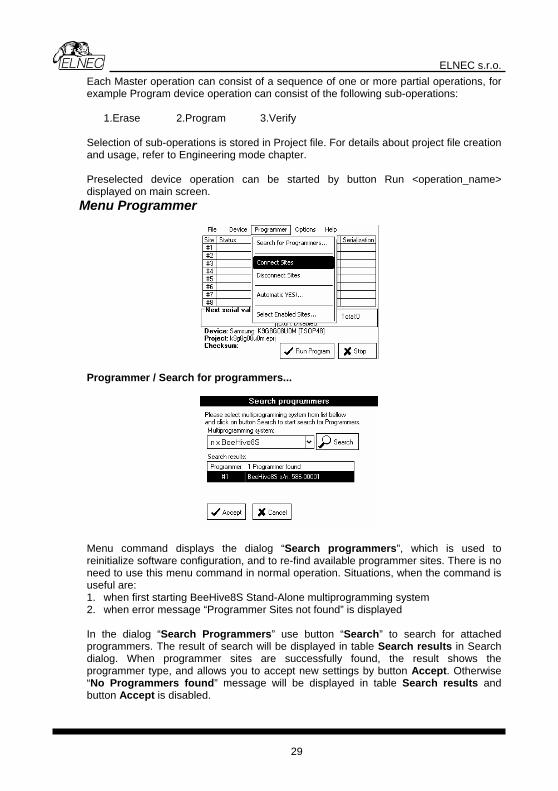
Menu Programmer
Programmer / Search for pro
grammers...
Menu command displays the dialog “Search programmers”, which is used to reinitialize software configuration, and to re-find available programmer sites. There is no need to use this menu command in normal operation. Situations, when the command is
seful are: Stand-Alone multiprogramming system
. when error message “Programmer Sites not found” is displayed
“Search Programmers” use button “Search” to search for attached p result of search will be displayed in table Search results in Search dialog. When programmer sites are successfully found, the result shows the p pe, and allows you to accept new settings by button Accept. Otherwise “ mers found” message will be displayed in table Search results and button ept is disabled.
u1. when first starting BeeHive8S2 In the dialog
rogrammers. The
rogrammer tymNo Progra
Acc
29

ELNEC s.r.o.
If search result is “No Programmers found”, please try to turn off Stand-Alone programmer, by menu “File / Shut down computer”, turn off the power button on the
ack side of programmer, wait for 15 seconds or more and start programmer again. If the ”, please refer to troubleshooting
ocumentation.
enu command starts control applications for all available programmer sites. The
ction progress is displayed for each site in the Status panel
r sites are numbered from #1 to #8 in direction of physical placing of sites from left to right. When connection process of is complete, indicator “Connecting Sites” will be hidden. The Status panel will contain information about each site. Following status information are most common: • Ready means the programmer site is connected and ready to start any
operation • Present special status of connected site, means the site is connected but it is
also not selected (checked in dialog Select sites). User selected device or project operations will not run on Present (unselected) sites. User can set site selection in dialog 'Select si ' accessible by menu
lect Enabled sites'. • No project file is loaded – means the site is successfully connected but no project
file is loaded. It also means that no device is selected. The recommended action is “Load project“.
• other text describes current status of site(s) Programmer / Disconnect Sites Menu command is used to disconnect all programmer sites and close Programmer sites control applications. The command will apply only if no device operation is currently running on any of connected sites. The command does not close main control program. Also Stand-Alone programmer computer remains running. Programmer / Automatic YES!...
ommand displays dialog “Site settings” with Automatic YES options.
b search result is still “No Programmers found
d Programmer / Connect Sites M“Connecting Sites“ indicator is displayed during connecting of sites. Additional information about site conneon the main screen. Programme
tescommand 'Programmer / Se
C !
Three modes of Automatic YES! function are available:
30

ELNEC s.r.o.
• On Automatic YES! Is always On • Off Automatic YES! Is always Off • Use Project settings Automatic YES! setting depends on relevant settings
stored in project file When Automatic YES! mode is after device operation is com
On, programmer sites are scanning their device sockets pleted. The control program can detect removing of
programmed device and insertion of new device and afterwards automatically start (repeat) recent operation on new device. So operator does not need to press any key or button, to program next device. When Automatic YES! mode is Off, operation on next device can be started manually, by pressing the YES! button near each programmer site socket. Each programmer site has its own YES! button. Status of the active Automatic YES! function is displayed on the bottom left side of LCD main screen with label Automatic YES! Is On by following:
If the Automatic YES! function is Off, no label about Automatic YES! is displayed.
rogrammer / Select Enabled Sites... nabled Sites”.
For more details about Automatic YES! feature see documentation chapter Programmer / Automatic YES!. PCommand displays dialog “Select E
Each te is represented by one heck box. If the check box #n is checked, it means the site #n is selected, and device
This dialog is used to select sites that have to be used. sic
31

ELNEC s.r.o.
operations will run on it. If th the site #n is unselected, so no device operations will run et as selected or unselected a uri
M nu Options
e check box #n is unchecked, on the Site. The sites can be s
nytime needed, except d ng running device operation.
e
Options / Settings... Command displays dialog “Settings” with list of options, user can choose from and set their properties and/or settings.
Log file... Log file settings screen looks as following:
Log file is text file containing information about Pg4uwMC control program operation ow, which means information about loading project files, device operation types and fl
device operation results.
32
ELNEC s.r.o.
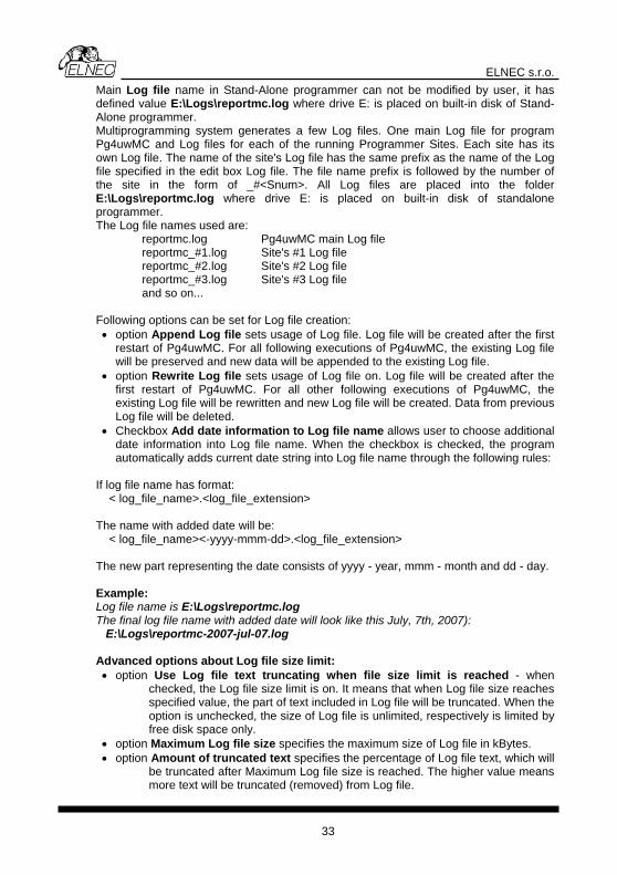
Main Log file name in Stand-Alone programmer can not be modified by user, it has defined value E:\Logs\reportmc.log where drive E: is placed on built-in disk of Stand-Alone programmer. Multiprogramming system generates a few Log files. One main Log file for program
g files for each of the running Programmer Sites. Each site has its s Log file has the same prefix as the name of the Log
ied in the edit box Log file. The file name prefix is followed by the number of the site in the form of _#<Snum>. All Log files are placed into the folder E:\Logs\reportmc.log where drive E: is placed on built-in disk of standalone programmer. The Log file names used are:
reportmc.log Pg4uwMC main Log file reportmc_#1.log Site's #1 Log file reportmc_#2.log Site's #2 Log file reportmc_#3.log Site's #3 Log file and so on...
ollowing options can be set for Log file creation:
g file sets usage of Log file. Log file will be created after the first
ill be appended to the existing Log file. • option Rewrite Log file sets usage of Log file on. Log file will be created after the
first restart of Pg4uwMC. For all other following executions of Pg4uwMC, the existing Log file will be rewritten and new Log file will be created. Data from previous Log file will be deleted.
• Checkbox Add date information to Log file name allows user to choose additional date information into Log file name. When the checkbox is checked, the program automatically adds current date string into Log file name through the following rules:
If log file name has format: < log_file_name>.<log_file_extension> The name with added date will be:
_name><-yyyy-mmm-dd>.<log_file_extension>
he new part representing the date consists of yyyy - year, mmm - month and dd - day. Example: Log file name is E:\Logs\reportmc.log The final log file name with added date will look like this July, 7th, 2007): E:\Logs\reportmc-2007-jul-07.log Advanced options about Log file size limit: • option Use Log file text truncating when file size limit is reached - when
checked, the Log file size limit is on. It means that when Log file size reaches specified value, the part of text included in Log file will be truncated. When the option is unchecked, the size of Log file is unlimited, respectively is limited by free disk space only.
r Maximum Log file size is reached. The higher value means more text will be truncated (removed) from Log file.
Pg4uwMC and Lown Log file. The name of the site'o
file specif
F• option Append Lo
restart of Pg4uwMC. For all following executions of Pg4uwMC, the existing Log file will be preserved and new data w
< log_file T
• option Maximum Log file size specifies the maximum size of Log file in kBytes. • option Amount of truncated text specifies the percentage of Log file text, which will
be truncated afte
33

ELNEC s.r.o.
Display settings...
Display e invert display mode”. When the checkbo scre inverted” mode. Otherwise it will be displa l mode.
C
settings dialog contains check box “Usx is checked, LCD en will be displayed in “yed in norma
Touchpad calibration...
ommand is used for calibration of built-in touch pad, part of built-in LCD touch screen.
The calibration of touchpad is recommended if you encounter unexpected reactions
alibration with Yes button, blank screen with point
uired number of points, touchpad calibration is complete, which will be
ayed.
from touchpad. If user confirms dialog about touchpad calibration procedure will start. Calibration procedure will showc
displayed. User has to click on the point with stylus. There will be sequentially displayed w points at different positions. Each of the point has to be clicked by user. Afterfe
clicking reqannounced by information message displ Sounds...
34
ELNEC s.r.o.
Dialog Sounds settings allows user to select the sound mode of program. Program generates sounds after some activities, e.g. activities on device (programming, verifying, reading, etc.). Program generates sound also when warning or error message is displayed. User can now select sound from MS Windows system sound (requires installed sound card), PC speaker or No sound. The check box “Use beep sound on touch screen press” allows to switch beep sound on or off. When the checkbox is checked, beep sound will be generated on each touch screen press, that software detects. Otherwise no beep sound will be generated. Options / Statistics...
Command displays dialog “Statistics”. Statistics gives the information about actual count of device operations, which were proceeded on selected type device. If one device is corresponding to one device operation, e.g. programming, the number of device operations will be equal to the number of programmed devices. Statistics dialog contains following options: Check boxes: Program, Verify, Blank and Erase which define operations, after which statistics values increment.
ny selected and performed device operation will increment the counter and one
. Count down allows checking of the umber of device operations, and then the number of devices, on which device
have to be done. After each successful device operation the value of count down counter is decremented. Count down has user defined start number for devices to do. When count down value reach zero, it means, the specified number of devices is complete and a user message about complete count down will be displayed. Check box Enable Count down sets Count down activity (enable or disable). Edit box following the Enable Count down check box defines initial number of count down counter, from which count down starts. Actual statistics values are displaying in main window of control program in Statistics
anel.
A Totalof the Success or Failure counters depending on device operation result (success or failure). A combination of partial operations is counted as one operation only. For example, a Read operation including Verify after Read is one operation. A Program operation including Erase and/or Verify operations is counted as one operation. The next function of statistics is Count downnoperations
p
35

ELNEC s.r.o.
Statistics panel contains: three statistics values Good, Fail, Total. two Count down information values Ctdn status and value. Meaning of the values is: Good - number of operations which where successfully completed
emains - informs about remaining number of device operations to do
Notes: When project file is loaded all statistics values are set to zero and Ctdn is set to Disabled. For multiprogramming Pg4uwMC software, the statistics information is also saved to Job Summary report. Options / View Log...
Fail - number of operations which where not successfully completed Total - number of all operations Ctdn - informs about Count down activity (En (enabled) or Disabled) R
Command displays content of current Log window. At top right corner is the button [x],
/ Protected mode...
settings due to significance. Protected mode is suitable especially for the programming of a large
uring next tart of program Pg4uwMC the Protected mode settings from .ini file are used.
rm the password is correct. After successful assword confirmation program switches to Protected mode.
which is used for closing the Log window and displaying of main screen. Options Protected mode is special mode of the program. When the program is in Protected mode, there are disabled certain program operations and commands. Protected mode is used to prevent the operator from modifying program or deviceinamount of the same type of devices. Protected mode can be activated by this menu option or by loading project file that has activated Protected mode. Protected mode settings are saved to configuration .ini file of Pg4uwMC. Ds When Protected mode menu command is used, password dialog will appear. User has to enter password twice to confip
36

ELNEC s.r.o.
There is also available one special option - Keep "Load project" operation allowed.
he option is set to disabled at default - it means the Load project operation button and
d (checked), the Load project operation button and menu will be lowed in Protected mode.
Protected mode back to Normal mode, use the menu command Options / Normal mode. The "Password required" dialog appears. User has to enter the same password as the password entered during switch to Protected mode. When Protected mode is active, the label "Protected mode" is visible near the top of Status table of main LCD screen. Notes: Sometimes when Protected mode is switched from active state to inactive state (Normal mode), some commands (for example command "Load project") may remain disabled. This can be resolved by clicking on button Stop. When user forgot the password to turn off Protected mode, then protected mode can be turned off by administrator, by entering Administrator password. Administrator login is
ot necessary.
M
useful when an error occurs in the control program or
cturer to
updates. After selecting is item, program will display question “Are you sure?”. If user confirms the question
with answer Yes, dialog “Select installation package” will be displayed.
Tmenu will be disabled when Protected mode is active. If the option is enablealTo switch program from
n enu Help
Help / Index Menu command displays short help on built-in touch screen. The short help contains brief information about menu commands and basic operations with usage of touch screen. Help / Problem report... Menu command “Create problem report” is used for writing more particular diagnostic information to Log window and consequently copy Log window content to problem report file. Problem report isprogrammer and that the user can not resolve and he must contact programmer manufacturer. In this case when customer send message to manufacturer about his problem it is good to send also problem report. Problem report can help manufalocalize the reason of error and resolve it sooner. Help / Update software... This important menu command allows users to make software th
37
ELNEC s.r.o.
In this dialog user can browse for the “pg4uwarc” installation package he wishes to
plugged into USB port of Stand-
ey, will appear in list of available drives in dialog “Select
hen user confirms another confirmation dialog, update process will start.
install. The installation package can be copied before, to shared Stand-Alone folder via network, or it can be stored on a USB key which can beAlone programmer. When USB key is plugged to USB port of programmer, new drive letter, assigned with USB kinstallation package”. User can than select this drive and run installation package from the USB key. W
uring update pD rocess, control program of Stand-Alone programmer is closed, LCD blank for some moments and after installation is complete, automatic dalone programmer will be performed. Whole process should not exceed nutes.
panel can berestart of stantime of 1-2 mi Help / About...
Welcome screen is displastarting of standalone con
yed on standalone's build-in LCD screen after successful trol software. The screen can be also displayed by using
menu command 'Help / About'. Welcome screen contains following basic information: • version of control software
38

ELNEC s.r.o.
• programmer type • number of Sites available • operating system • information about processor and size of installed RAM memory • computer name and IP address • system date and time
Welcome screen can be closed by clicking on button OK.
Administration of build in PC In
ccounts
Credentials for BeeHive8S Stand-Alone multiprogramming system users are: Login Password Administrator admin saadmin Operator operator saoperator
Network administration C
ammer is started it will show “Welcome”/“About” screen. On reen in line “IP address:” is the address obtained from DHCP server.
127.0.0.1, then no network cable is connected, DHCP server is not running when device start or other kinds of error occur – refer to troubleshooting chapter.
troduction • BeeHive8S Stand-Alone multiprogramming system is powerful programmer
equipped with Windows XP Embedded operating system (“OS”). There are two major kinds of administration of the OS – network and local. OS is configured with two users a
• admin • operator.
onnecting to network OS in programmer is configured for operating with TCP/IP network. To obtain correct IP address, the configured DHCP server must run in your local network, when programmer
starting. After progrisbottom part of scWhen IP address is equal to
39
ELNEC s.r.o.
RAdministering of BeeHive8S Stand-Alone multiprogramming system is performed t te Desktop Connection”. Remote desktop offers fast and c ), distribute project fF Desktop Connection” program on your computer. In
mputer” field enter IP address from “Welcome” screen of standalone programmer.
emote control
hrough Microsoft “Remoomfortable way to update software (control software and systemiles ... ind and run “Remote
“Co
When communication is established enter administrator credentials.
Because Windows allows only one user connected at a time, next message may be showed.
40

ELNEC s.r.o.
Warning: Connecting to programmer in time, when programming devices is running,
Local administration For local administration of Stand-Alone programmer you must have connected standard PS/2 keyboard, PS/2 mouse, and standard analog display with resolution 1024x768 and 32bit color supported. Operating disk is divided to three volumes. First volume named as “Recovery” (C:) contains software for OS recovery of programmer to state as shipped from factory. Standard start time of programmer is about 2 minutes. When device doesn't start in 10 minutes, then it may be necessary to perform OS recovery. Before operating system recovery, connect monitor to programmer, and kindly report what you see to rogrammer manufacturer. For next steps refer to “Operating system r covery”
s XP Embedded operating system. Warning: Do not delete, change files or perform any writes on “Recovery” or “System” disk volumes. Third volume is named as “Data” (E:). This volume contains Programmer, Projects, Logs, Updates and Temp directories. Programmer is directory, where main control software is installed. In directory Logs are saved log files from operations with devices. When OS update files are available, they should be saved to Updates directory. Your project files should be in Projects directory. Exact update steps will be distributed with operating system updates. For programmer reliability operating system is configured with write filters on “Recovery” and “System” disk. As a side effect of these filters, any configuration changes in entire operating system will be wasted after restart or shutdown programmer.
Operating system recovery Recovery OS performs refreshing of programmer operating system to state as it was shipped from factory.
efore operating system recovery, connect monitor to programmer, and kindly report
n programmer. After starting BIOS screen Windows show this screen:
programming will be immediately terminated – your devices may not be fully programmed. Restart computer after you finish remote administering. Because work with remote desktop is similar to working on local station, please continue to read chapter “Local administration”.
epchapter. Second volume is “System” (D:), and contains Window
Bwhat you see to programmer manufacturer. To perform operating system recovery you must have connected keyboard, mouse and
splay. Turn odi
41

ELNEC s.r.o.
With arrow keys (up or down) select “Windows Recovery” and press Enter. Recovery system will be started. Please be patient. This can take about four minutes. Then EULA license will show. Please read carefully this license agreement,
ccepting agreement starts formatting of disk D:, and installation of control program mer directory on disk E:, and creates new one). Also mp has been erased and recreated. When recovery is
close window, press “A” if you accept this agreement. A(recovery deletes Programdirectories Updates and Tecompleted, you should see “System recovery completed.”. Then press any key, and system will restart. First start of the operating system after recovery may be a bit longer, with one additional restart.
42

ELNEC s.r.o.
Troubleshooting and warranty
Troy our product. Nevertheless, problems can occur. In such
cases please follow the instructions below. • It might be your mistake in not properly operating the programmer or its control
program • Please read carefully all the enclosed documentation again. Probably you will find
the answer right away. • Ask your in-house guru (every office has one!). • Ask the person who already installed the programmer.
• If the problem persists, please call the local dealer, from whom you purchased the
programmer, or call ELNEC direct. Most problems can be solved by phone, e-mail or fax. If you want to contact us by: • Mail/fax - Copy the "DEVICE PROBLEM REPORT" form and fill it in following the
instructions at the end of the form. Write everything down that you consider being relevant about the programmer, software and the target device. Send the completed form by mail or fax to ELNEC (fax number in the control program, menu Help / About) or to your local dealer. If you send the form by fax please use black ink, a good pen and large letters!
• E-mail - Use "DEVICE PROBLEM REPORT" form on the CD or from our Internet site and fill it in following the instructions at the end of the form. Use standard ASCII editor. Write everything down that you consider being relevant about the programmer, software and the target device. Send the completed form by e-mail to your local dealer or to ELNEC ((nospam version) elnec at elnec dot com).
• Phone - Copy "DEVICE PROBLEM REPORT" form and fill it in following the instructions at the end of the form. Write everything down that you consider being relevant about the programmer, software and the target device. Send the completed form by mail or fax to ELNEC (fax number in the control program, menu Help / About) or to your local dealer. If you send the form by fax please use black ink, a good pen and large letters easily to read. Then call your local dealer or ELNEC's customer support center (phone number in the control program, menu Help / About). Please keep your manual, the programmer and the completed "DEVICE PROBLEM REPORT" form (just faxed) available, so that you can respond quickly to our questions.
• If your programmer is diagnosed as defective, consult your local dealer or ELNEC about the pertinent repair center in your country. Please carefully include the following items in the package: • defective product • completed "DEVICE PROBLEM REPORT" form • photocopy of a dated proof of purchase
ubleshooting We really want you to enjo
43

ELNEC s.r.o.
Note: You may find the "DEVICE PROBLEM REPORT" form at our Internet site
Without all these items we cannot admit your programmer for repair.
(www.elnec.com), section 'Su Warning:
pport'.
ich case the user may be required to take
Because BeeHive8S have interna•
• mer from mains.
If y uIf ypro • Lo
(sm
• indein
No
Se
Class A ITE notice Devices described at this manual are class A products. In domestic environment this
roducts may cause radio interference in whpadequate measures.
l power supply, follow these special precautions: Circuit breakers (overcurrent protection) must be a part of building electrical installation. Pull out power cord plug from outlet to disconnect program
o have an unsupported target device ou need to operate on a target device not supported by the control program for grammer, please do not despair and follow these next steps:
ok in the device list of the latest version of the control program on our Internet site ection Download, file corresponded to your programmer). Your new target device ight already be included in this version! If yes, download the file PG4UWARC.exe d install the new version of the control program.an
Contact ELNEC direct, filling up a "Device Problem Report" form following the structions at the end of this form. We may need detailed data sheets of your target vice and, if possible, samples. The samples will be returned to you after we
clude your target device in a new version of control software.
te: e also AlgOR service at our Internet site (www.elnec.com), section 'Support'
nance ecommend following the instructions and precautions herein to achieve high lity of the programmer for a long period of time.
programmer maintenance depends on
MainteWe rreliabi The character and amount of its use.
• • tion of debris and dust in ZIF socket. • mer with enclosed dust cover. • osition near a source of heat.
Dail maintenance
Regardless, the following recommendations are generally accepted: Do not use and store the programmer in dusty places. Humidity accelerates sedimentaAfter end the job cover the ZIF socket of the programDo not expose the programmer to direct sunlight or p
44
y

ELNEC s.r.o.
Check the ZIF sockets of the programmer and the socket converters for their condition and wear. R with clean, dry and compressed a osition. Weekly main
erform the “Selftest plus” for every programmer or programming module. rly maintenance
rogrammer supports this feature. tenance
Tc 25.000 m
ized BGA devices,
environment and ZIF maintenance have direct influence to actual electrical lifetime of
ures. Change the ZIF
Thelarg
Warrhe ntee on failure-free
g of the BeeHive8S Stand-Alone multiprogramming system, including protective ing-
in allow er warranty on ZIF sockets or 10,000-cycles on other ZIF sockets). much care as possible to integrate high quality components in the
build in computer, we can't provide higher warranty as we get from suppliers. So there
authorized repair centre
F purchase. T
t r Elnec seller’s warranty policy.
emove debris, dust and grime from the ZIF sockets ir. Clean the ZIF sockets both in closed and opened ptenance
PQuarteGently clean the surface of the programmer with isopropyl alcohol or technical alcohol on a soft cloth. The LCD clean with a soft cloth moisten in water only. Isopropyl alcohol
ay damage surface of the LCD. mPerform the calibration test if the pBiannual mainCheck amount of dust or dirty in programmer. If you feel that a lot of dust or dirty is in programmer, clear it by vacuum cleaner. The warranty does not apply to any damage of programmer or its part caused by dust or
rt. diIf you want, you can send programmer to ELNEC for this maintenance. Warning:
he ZIF socket of the programmer and the socket converters are considered as onsumables. The life cycle of the ZIF socket of the programmer' is about echanical cycles. The life cycle of ZIF sockets of the socket converters is in generally
from 5.000 to 10.000 mechanical cycles, even if the life cycle of some specialZIF sockets can be about 500.000 mechanical cycles. Programmed
ZIF socket (it means that ZIF socket does not cause programming failures yet). Keep fingers away from contacts of ZIF socket, because contacts of the ZIF socket fouled by mear and grime from fingers may cause the programming fails
socket or the socket converter if you noticed increased number of programming failures.
warranty does not apply to the ZIF sockets that are wear or grimy and which cause e amount of failures during working with programmer.
anty terms manufacturer, ELNEC s.r.o. Presov, Slovakia, gives a guaraT
operatincircuits, original brand components, and careful manufacturing and hours-long burn
s us to provide a three-year warranty on parts and labor for the programm(limited 25 000-cycleAlthough we take as
is a limited warranty of one year on all computer parts such as Motherboard, CPU, HD, ... .
the product is diagnosed as defective, ELNEC s.r.o. or theIfwill repair or replace defective parts at no charge. Parts used for replacement and/or whole programmer are warranted only for the reminder of the original warranty period.
or repair within the warranty period, the customer must prove the date of
hese warranty terms are valid for customers, who purchase a programmer directlom Elnec. The warranty conditions of Elnec sellers may differ depending on the targe
yfrcountry law system o
45

ELNEC s.r.o.
The warranty does not apply to products that are of wear and tear or mechanically damaged. The warranty does not apply to any damage of programmer or its part
Equally, the warranty does not apply to products opened and/or cts that have
cidentally damaged or that were improperly installed.
e. ELNEC or its distributors will determine whether whether or not the
caused by dust or dirt. repaired and/or altered by personnel not authorized by ELNEC, or to produbeen misused, abused, ac For unwarrantable repairs you will be billed according to the costs of replacement materials, service time and carriagthe defective product should be repaired or replaced and judge warranty applies.
ELNECreliableerrors buyer. ELNEC• Da• Da• An
“buFor exagainsimposs
Manufacturer: : ELNEC s. r. o., Jana Bottu 5, SK - 08001 Presov, Slovakia : +42151/77 34 328, 77 31 007, fax 77 32 797
www.elnec.com, e-mail (nospam version): elnec at elnec dot com
from claims of third parties or loss of recorded data or files, renown, loss caused by
has used its best efforts to develop hardware and software that is stable and . ELNEC does not guarantee that the hardware and software are free of "bugs", or defects. ELNEC's liability is always limited to contract's net value paid by a
is not liable for: mage caused by inappropriate use or handling of products. mage caused by users or third parties modifying or trying to modify products. y further damage or consequent damage caused by hardware errors or software gs”. ample: lost profits, lost savings, damages arisedt a client, damage ibility to use etc.
46