user's guide - welcome to kirkwood cables, llc€¦ · installing the usb drivers the...
TRANSCRIPT

User's Guidefor the
USB GagePort Cables
Printing Date: April 13, 2016
www.KirkwoodCables.com
User's Guide Version 1.30
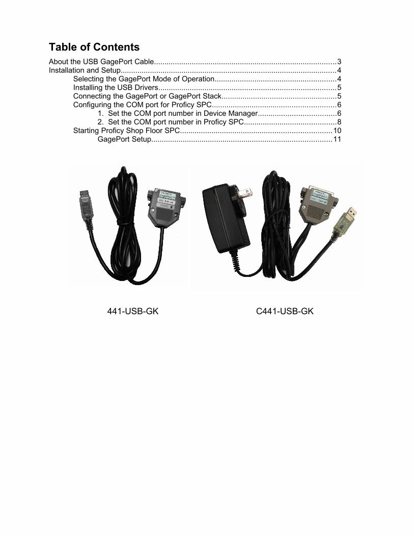
Table of ContentsAbout the USB GagePort Cable.......................................................................................3Installation and Setup.......................................................................................................4
Selecting the GagePort Mode of Operation..........................................................4Installing the USB Drivers.....................................................................................5Connecting the GagePort or GagePort Stack.......................................................5Configuring the COM port for Proficy SPC...........................................................6
1. Set the COM port number in Device Manager.....................................62. Set the COM port number in Proficy SPC............................................8
Starting Proficy Shop Floor SPC........................................................................10GagePort Setup......................................................................................11
441-USB-GK C441-USB-GK

About the USB GagePort Cables
The USB GagePort Cables (441-USB-GK and C441-USB-GK) from Kirkwood Cables, LLC provide a direct connection between a GagePort (GP-2102NT, GP-3102NT, GP-2104NT, etc.) and a USB port on a computer. They are intended as USB alternatives to the G-C440, G-C441, A-680 and A-681 cables used to connect a GagePort to a serial COM port on a computer. The USB GagePort Cables are compatible with Proficy SPC but do not contain the hardware key found in the A-68x cables, which was required by older versions of VisualSPC.
As USB ports have replaced COM ports on most computers, until now it has been necessary to adapt the G-C44x or A-68x cables to USB by using a serial-to-USB converter. In addition, the G-C44x and A-681 cables use a clunky charger to connect the GagePort to wall power. The 441-USB-GK makes the GagePort into a much more portable device by connecting the GagePort directly to USB and by powering it from the USB port.
Because the 441-USB-GK draws power from the USB port, it is limited to the power that a USB port can provide, about 400mA at around 5V. It is therefore intended for “light” GagePort applications using a single GagePort or a small stack of GagePorts (up to about 6 Digital GagePorts, depending on what power is drawn by the gages). The 441-USB-GK is not recommended for use with analog or LVDT GagePorts.
The C441-USB-GK is for “heavier” applications and has the same wall charger used on the G-C440, G-C441, A-680 and A-681 cables. The C441-USB-GK is recommended for use with analog and LVDT GagePorts.
Overview of features of the 441-USB-GK:
• The GagePort or GagePort stack is powered from the USB port.
• The internal jumper selects between Computer Mode (used with Proficy SPC) and Printer Mode (used in most other applications).
• The power light shines Green when the cable is properly powering the GagePort, and Red in the case of an overload condition.
• Current limiting allows the 441-GK-USB to provide a minimum of 400mA and a maximum of 440mA to the GagePort or GagePort stack.
• The reset switch used to reset the GagePort is identical to that in the G-C44x and A-68xcables.
• Lead free! The 441-USB-GK is RoHS compliant.
Overview of features of the C441-USB-GK:
• The GagePort or GagePort stack is powered from a wall charger.
• The internal jumper selects between Computer Mode (used with Proficy SPC) and Printer Mode (used in most other applications).
• The reset switch used to reset the GagePort is identical to that in the G-C44x and A-68xcables.
• Lead free! The 441-USB-GK is RoHS compliant.
If you have questions or feedback, please tell us at www.kirkwoodcables.com/contact-us.html.
Page 3

Installation and Setup
Selecting the GagePort Mode of Operation
The 441-USB-GK and C441-USB-GK has an internal jumper that selects between the two GagePort modes:
• Computer Mode – 9600-7-N-2 – This is the mode that Proficy SPC uses to communicate with a GagePort via a set of commands.
• Printer Mode – 9600-8-N-1 – This is the mode used for most other purposes. If using this mode, set your software COM port settings to 9600-N-8-1.
The default factory setting in the 441-USB-GK and C441-USB-GK is Computer Mode, unless otherwise requested.
Below are photographs of the two jumper settings. In order to change the GagePort Mode, simply remove the hood of the 441-USB-GK or C441-USB-GK and change the jumper setting inside.
Computer Mode – 9600-7-N-2 Printer Mode – 9600-8-N-1
The photos shown here are from the 441-USB-GK. The C441-USB-GK has a different internal appearance, but it has the same jumper that functions in the same way.
Page 4

Installing the USB Drivers
The 441-USB-GK and C441-USB-GK utilizes a “Virtual COM Port” (VCP) so that Proficy SPC or other software will recognize and communicate with a GagePort as if it were connected through a standard COM port, even though the physical connection is USB. Therefore, USB drivers that support the VCP must be installed. These drivers can be found on the User's Guide and Drivers Disc included with the 441-USB-GK and C441-USB-GK cables. Alternatively, the latest drivers can be downloaded from: http://www.ftdichip.com/Drivers/VCP.htm
To install the drivers, connect the USB end of the cable to a USB port of the computer. The computer will automatically look for drivers and install them if they are already present on the computer. If the drivers are not found automatically, browse to the Drivers Disc CD or other location where the drivers have been downloaded.
Once the drivers have been installed, a message may appear on the screen indicating that the device is ready to use. Also, the power light on the 441-USB-GK should shine Green once the drivers are installed, indicating that it is powered up and ready to use.
If more detailed installation instructions are needed for your particular operating system, installation guides can be found http://www.ftdichip.com/Support/Documents/InstallGuides.htm
Connecting the GagePort or GagePort Stack
The 441-USB-GK has the ability to run a single GagePort or small GagePort Stack. Simply plug the 25-pin end of the 441-USB-GK into the GagePort or GPA-100 GagePort Multiplexer.
In our experience the 441-USB-GK will run up to about 6 Digital GagePorts at a time, depending on what gages are connected. The Green power light will turn to Red if an overload condition is reached. If the Green light flashes Red during GagePort reset, that is a good indication that no more gages or GagePorts should be added to the stack.
Kirkwood Cables LLC makes no guarantees as to how many GagePorts or gages can be connected to the 441-USB-GK at one time, as that will depend on your application.
The C441-USB-GK will power any GagePort or GagePort stack of any size.
Page 5

Configuring the COM port for Proficy SPC
1. Set the COM port number in Device Manager
Since Proficy SPC only recognizes ports 1 through 4 for data collection, the COM port number will need to be adjusted if it is not already assigned within that range. When first connecting either of the USB GagePort Cables (441-USB-GK or C441-USB-GK), the Virtual COM port maywell have been assigned a COM number higher than 4.
In the case of this example, the Virtual COM port was automatically assigned to COM 11, whichis outside the acceptable range for Proficy SPC. Therefore, this will need to be adjusted in the Windows Device Manager.
To accomplish this, open the Device Manager. This can easily be done by typing “Device Manager” in the Windows Start menu search box as shown below. The Device Manager can also be found in the Control Panel.
When the Device Manager is found, as shown above, click on it to open the Device Manager.
Before the Device Manager starts, you may see a message box that says, “Windows needs your permission to continue.” If so, click the “Continue” button to continue.
Page 6

When the Device Manager opens, expand the list of Ports (COM & LPT) as shown below. Double-click on the port you'd like to adjust (COM 11 in this example):
The Serial Port Properties box opens. Select the Port Settings tab (circled below) and then click on the “Advanced...” button, as shown:
Page 7

In the Advanced Settings box, select a different COM port from the COM Port Number drop down list, preferably one that is not “in use.” Any COM port number between 1 and 4 is acceptable. In the case of this example, COM 3 is selected. Click “OK” when done. If needed,also click “OK” to close the Properties box, and also close the Device Manager, as the port number adjustment is now complete.
2. Set the COM port number in Proficy SPC
Proficy SPC needs to be set up ahead of time in order to know which COM port to use with the USB GagePort Cable. From the Start menu, select “All Programs,” and then open the Configuration Manager, which can be found under Proficy Shop Floor SPC... Administrative Tools, as shown:
Page 8

The following box will then appear. Make sure “Data Collection” is selected, then click “OK.”
In the Proficy Shop Floor SPC Data Collection Configuration Options box, select the Gage Inputtab (circled below). If you are using a foot switch in your application, check the “Use Footswitch” box. Otherwise, leave it unchecked. Click on the “GP Setup” button.
In the GagePort Setup box, select the appropriate COM port from the drop-down list to match that earlier assigned to the USB GagePort cable (COM 3 in this case). Verify that the baud rateis set at 9600. Click “OK” to close the GagePort Setup box, and click “OK” again to close the Configuration Options box. The COM port is now configured for Proficy SPC.
Page 9

Starting Proficy Shop Floor SPC
To start Proficy SPC, go to the Start menu, select “All Programs,” and then open Data Collection, which can be found under Proficy Shop Floor SPC as shown:
There may be a few message boxes that come up when starting Proficy SPC. Just click “OK” to close these. On the following screen, double-click on the path to “GAGE.VSG” as shown:
Page 10

GagePort Setup
Before using Proficy SPC to collect data, be sure to set up the GagePorts, to make sure that allGagePorts are detected. From the Gages menu, select “GagePort Setup”, which opens the box below. Click on the “Start” button to begin detecting the available ports:
Notice the Green light on the USB GagePort Cable to see if it flashes Red while the GagePorts are detected. If the Red light comes on during the setup process, that is a good indication that the size of the GagePort stack is very close to the maximum load capacity of the USB port.
When this process completes, you will see something similar to the box below:
As you can see circled on the left, there have been three 2104 GagePorts detected, and accordingly 12 ports are displayed in the circle on the right. This example shows the results of successfully detecting three 4-port GagePorts (GP-2104NT).
Click OK to return to the GageSheet.
If you have any suggestions or feedback, or need further information or support, please contactus at www.kirkwoodcables.com/contact-us.html.
Page 11