user’s guide - oasis scientific
TRANSCRIPT

User’s Guide DiGi Microscope
Version 1.0A

1
Content
1. Products Introduction .......................... 3 1.1 Packing Contents ......................... 3 1.2 IR remote controller .................... 3 1.3 Microscope introduction: .......... 11 1.4 Microscope focus ....................... 14 1.5 Change microscope Object lens 17 1.6 Microscope accessory................ 20
2. Install Application Program ............... 21 2.1 Insert CD to CD-ROM ................. 21 2.2 Install Application Program ....... 21 2.3 Exit Install Program .................... 21
3. Application Program Operation ......... 22 3.1 Video Preview Window ............. 23 3.2 Image Preview Window ............. 23 3.3 Main Menu ................................ 23 3.4 Main Button ............................... 23 3.5 Files List ..................................... 25

2
3.6 Function modes ......................... 25 4. Printed Notice .................................... 27
4.1 Maintenance .............................. 27 4.2 Product Specification ................. 28 4.3 Safety Instructions ..................... 29

3
1. Products Introduction 1.1 Packing Contents
There are 1 microscope and 10 accessories in the box. The Object Lens 4X is already assembled onto microscope. If object lens needs to change, please refer to Section 1.5.
Item Q’ty Item Q’ty
DiGi Microscope 1 White Balance Card 1
HDMI Cable 1 Calibrator 1
USB 2.0 Cable 1 User’s Guide 1
Power adaptor 1 Install CD 1
S107 Stand 1 Object Lens 4x 1
Stand assemble guide 1 Object Lens 10x Option
1.2 IR remote controller The Digi Microscope is control by IR remote controller or application program.
When enable the far distance control mode from application program, the remote controller is only used for Power, PC Cam or HDMI. There are 3 groups on the remote controller to use in different mode: Common use, PC Cam and HDMI.
1.2.1 Buttons for Common use
The said buttons are used both for PC Cam and HDMI mode.
(1) Power :Turn on/off.
(2) LED Adjustment: Adjustable 12 levels of brightness.
(2-1) Increase :Increase LED brightness.
(2-2) Decrease :Decrease LED brightness.
(2-3) On/Off :Turn on or off the LED. When turn on the LED, the
brightness will return to the situation before turn off.
(3) Motor Reset (Calibrate of whole operation):To go back to the lens

4
position. If electricity black out occurred during operation, please reset the whole operation.
(4) Manual focus
(4-1) Zoom in :Descending speed when press longer Zoom in.
(4-2) Zoom out :Descending speed when press longer Zoom out.
(4-3) Step zoom in :zoom in by steps.
(4-4) Step zoom out :zoom out by steps.
Microscope remote controller Buttons for common use
5
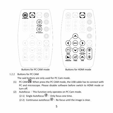
1.2.2 Buttons for PC CAM
The said buttons are only used for PC Cam mode.
(1) PC CAM :When press the PC CAM mode, the USB cable has to connect with
PC and microscope. Please disable software before switch to HDMI mode or turn off.
(2) Autofocus:This function only operates on PC Cam mode.
(2-1) Single Autofocus :Only focus one time.
(2-2) Continuous autofocus :Re-focus until the image is clear.
Buttons for PC CAM mode Buttons for HDMI mode

6
(3) Snapshot :Take 5M picture and delivery to Application program.
1.2.3 Buttons for HDMI
The said buttons are only used for HDMI mode.
(1) HDMI :When press HDMI mode, the HDMI cable has to connect with
screen and microscope.
(2) Menu on Screen :Open/close menu for setting.
(2-1) BRIGHTNESS:To adjust the brightness of whole image. [1~31]
(2-2) CONTRAST:To emphasis the difference between bright and dark. [1~31]
(2-3) SATURATION:To adjust the color level. [1~31]
(2-4) EXPOSURE VALUE:On/Off the exposure [ON/OFF]。
[ON] Auto mode, use with exposure value +/-. The adjust method please refer to Section 1.2.3-(7). This mode will adjust the image brightness automatically. Please turn on all LED to keep the best observation.
[OFF] Manual mode, use with LED brightness +/-. The adjust method please refer to Section 1.2.1-(2) and Section 1.2.3-(7). This mode
7
inquires to adjust LED brightness and exposure value +/-. The image brightness will change as the LED brightness and exposure value changed.
(2-5) SHARPNESS:On/Off the sharpness. [ON/OFF]。
[ON] the image is sharp. [OFF]the image is less-sharp, but more smooth.
(2-6) STATUS BAR:Show or not show the status bar on the screen top. please
refer to Section 1.2.3-(9). [ON] show the status bar on the top of screen. [OFF]close the status bar show on the screen.
(2-7) OBJECT LENS:Object lens type. (4x or 10x) When change another lens,
the setting needs to reset. Refer to Section 1.5. [4X] Object Lens 4x, turn on LED for lens 4x; in opposite, turn off LED
for lens 10x. [10X]Object Lens 10x, turn off LED for lens 4x; in opposite, turn on LED
for lens 10x. (2-8) LCD SIZE:Screen size. The current setting is only for 7”~80”.
(2-9) FACTORY:All setting return to factory setting.
[NO]the current setting. [YES]return to factory setting.
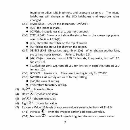
(3) Up :choose last item
(4) Down :choose next item
(5) Left :choose next value
(6) Right :choose last value
(7) Exposure Value: 13 levels of exposure value is selectable, from +0.2~-2.0.
(7-1) Increase :when the image is darker, add exposure value.
(7-2) Decrease :when the image is brighter, decrease exposure value.

8
(8) Video Ratio :Choose image ratio or Field of View. There are 3 types of
video ratio, press the button to next ratio. (8-1) 4/3F:4:3 means the image is from 5M image (2592*1944) output to fit
4:3 screen size. (The screen image: 1440*1080). Proportionally reduce the input image height to fit the screen.
(8-2) 16/9S:16:9S means the image from 5M (2592*1944) output to 16:9
screen size (the screen image: 1920*1080). Reduce input image horizontal proportionally to fit the screen, but trim the height. (Scaling) Magnification size becomes higher.

9
(8-3) 16/9C:16:9C means the image from 5M (2592*1944) output to 16:9
screen size (the screen image: 1920*1080). Crop image (1920*1080) from input image 5M (2595*1944); therefore, FOV become smaller, magnification become higher.
(9) Status Bar : On/Off to show or not show the status bar. Each color
represents different information.

10
(9-1) ZOOM:Zoom path, total 15 sections.
(9-2) FOV:Field of View, display image on the effective horizontal size of screen.
(9-3) M:Magnification. Magnification size changes depending on lens position,
screen size, and image ratio. Please refer to Section 1.4.2. (9-4) D:Distance, means the distance from object lens to object.
(9-5) EV:Exposure Value, please refer to Section 1.2.3-(7).
(9-6) LED:LED Levels, please refer to Section 1.2.1-(2).
(9-7) R:Video Ratio, please refer to Section 1.2.3-(8).
(10) Auto White Balance Calibration : Place the White balance card (included in box) under the lens, firstly focus til clear then choose On to calibrate white balance. Sometimes the white balance is influenced by environment light source or other light source, thus it’s suggested to calibrate white balance if the color is not correct.
11
(11) Image Freeze : On/Off image freeze. Freeze the image, press the button again to return to preview.
(12) Sharpness : On/Off sharpness mode. Please refer to Section 1.2.3-(2).
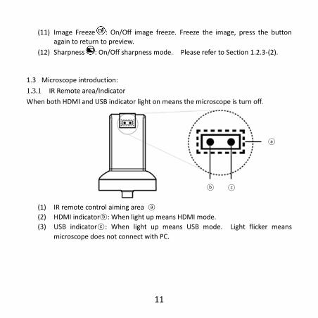
1.3 Microscope introduction:
1.3.1 IR Remote area/Indicator
When both HDMI and USB indicator light on means the microscope is turn off.
(1) IR remote control aiming area ○a
(2) HDMI indicator○b : When light up means HDMI mode.
(3) USB indicator○c : When light up means USB mode. Light flicker means
microscope does not connect with PC.
○b ○c
○a
12
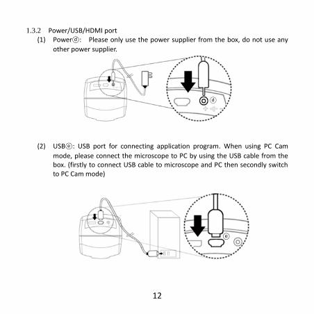
1.3.2 Power/USB/HDMI port (1) Power○d : Please only use the power supplier from the box, do not use any
other power supplier.
(2) USB○e : USB port for connecting application program. When using PC Cam
mode, please connect the microscope to PC by using the USB cable from the box. (firstly to connect USB cable to microscope and PC then secondly switch to PC Cam mode)
○e
○d

13
(3) HDMI○f :HDMI port for connecting screen. When using HDMI mode, please
connect the microscope to screen by using the HDMI cable from the box. *Note: if connect with TV screen, please choose the homologous image ratio and format.
1.3.3 Stand gear box
The universal joint as ○g . Firstly, assemble the stand then screw microscope to the
universal joint on gear box and fixed on stand.
○g
○f
14
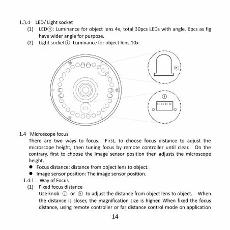
1.3.4 LED/ Light socket (1) LED○h : Luminance for object lens 4x, total 30pcs LEDs with angle. 6pcs as fig
have wider angle for purpose. (2) Light socket○i : Luminance for object lens 10x.
1.4 Microscope focus
There are two ways to focus. First, to choose focus distance to adjust the microscope height, then tuning focus by remote controller until clear. On the contrary, first to choose the image sensor position then adjusts the microscope height. Focus distance: distance from object lens to object. Image sensor position: The image sensor position.
1.4.1 Way of Focus (1) Fixed focus distance
Use knob ○j or ○k to adjust the distance from object lens to object. When
the distance is closer, the magnification size is higher. When fixed the focus distance, using remote controller or far distance control mode on application
○i
○h

15
program to tuning to clear image. (2) Fixed image sensor position
(2-1) In HDMI mode, the status bar will show on the screen, please refer to Section 1.2.3-(9). Use remote controller to adjust image sensor position based on magnification size, FOV, or distance height.
(2-2) In PC CAM mode, choose required height or FOV from drop down list on application program (see below fig).
When image sensor position is fixed, as (2-1) and (2-2), use knob ○j & ○k to
find clear image. Adjust the knob ○j in the beginning to the appropriate
height, then slightly adjust the knob ○k to find clear image.
○j
○k
○j
○k

16
1.4.2 Magnification chart
15 image sensor positions had set from the whole area, the image sensor position tells the magnification size, field of view, or height. The below chart is measured on 21.5” screen, it’s only a reference data, might not be accurate enough. Based on the image ratio, field of view and magnification size will change. Please refer to “F”, “S”, “C” in Section 1.2.3 – (8).
(1) Object lens 4X, focus distance from 1.95cm to 22cm (0.767 to 8.66inch).
Object lens 4X on 21.5” screen
Sensor position 1 2 3 4 5 6 7 8
Distance 22.0 15.2 9.70 7.35 5.75 4.75 4.15 3.65
F,S FOV 27.0 18.4 11.9 9.02 7.10 5.88 5.05 4.40
C FOV 19.9 13.6 8.80 6.67 5.25 4.35 3.73 3.25
F Magnification 13 20 30 40 50 61 71 81
S Magnification 17 26 40 53 67 81 95 109
C Magnification 23 34 54 70 90 109 127 145
Sensor position 9 10 11 12 13 14 15 unit
Distance 3.30 2.85 2.65 2.45 2.30 2.10 1.95 cm
F,S FOV 3.91 3.50 3.19 2.91 2.68 2.48 2.34 mm
C FOV 2.89 2.59 2.36 2.15 1.98 1.83 1.73 mm
F Magnification 92 102 112 123 134 145 154 X
S Magnification 122 137 150 164 179 193 205 X
C Magnification 165 183 201 221 241 261 277 X

17
(2) Object lens 10X, focus distance from 4.5mm to 7.7mm (0.177 to 0.303inch.
1.5 Change microscope Object lens
Object lens 10x is optional accessory. It comes with luminance, thus power supplier is needed. Please remove the power cable before change object lens.
1.5.1 Remove LED cover ○l
Unscrew 3 pc screws to remove LED cover.
Object lens 10X on 21.5” screen
Sensor position 1 2 3 4 5 6 7 8
Distance 7.70 7.10 6.70 6.40 6.10 5.89 5.60 5.41
F,S FOV 1.39 1.30 1.21 1.14 1.07 1.01 0.96 0.91
C FOV 1.02 0.96 0.89 0.84 0.79 0.74 0.71 0.67
F Magnification 260 279 297 318 336 360 378 395
S Magnification 346 371 395 423 447 479 503 526
C Magnification 468 502 534 572 604 648 680 711
Sensor position 9 10 11 12 13 14 15 unit
Distance 5.27 5.10 4.96 4.84 4.73 4.62 4.51 mm
F,S FOV 0.87 0.83 0.79 0.76 0.73 0.70 0.68 mm
C FOV 0.64 0.61 0.58 0.56 0.54 0.52 0.50 mm
F Magnification 413 439 455 480 493 145 154 X
S Magnification 550 585 606 639 657 694 705 X
C Magnification 743 790 819 964 887 937 952 X

18
1.5.2 Connect power cable
Plug in the power cable○m onto LED board socket○n . Pass through the
power cable out of LED cover○o . When remove, please never pull and drag
the power cable from inappropriate force, and hold the cable thread when disassemble.
○m
○n
○o
○l

19
1.5.3 Assemble LED cover
After power cable plugged onto LED board, grip the other head of power cable ○p and screw the LED cover ○q back.
1.5.4 Change object lens
Remove the original object lens ○r and replace with object lens 10x ○s ,
then screw lens tight. Please beware of dust into lens.
○r
○s
○q
○p

20
1.5.5 Luminance adaptor Insert the adaptor ○t onto lens, (the 2 sockets on LED board and adaptor
needs to face the same side). And plug in the power cable ○u onto adaptor○v
for luminance. This is for first time assembling.
1.6 Microscope accessory 1.6.1 Calibrator
Mainly use to calibrate the scale on application program, please refer to AP manual for more information. The calibrator is transparent, it can apply onto object directly.
1.6.2 White balance card
The white side is use for calibrate white balance. If the object is tiny, place the object onto white balance card (black/white side). Move the card to find focus spot instead of move the object.
○u
○t
○v

21
2.2
2.3
2. Install Application Program Please refer to the install manual inside CD for more details about install
application program. (User's Manual \English\Install manual.pdf) There are 4 steps to install ap: 2.1 Insert CD to CD-ROM. (Step 1)
Insert the CD (included in the box) into CD-Rom. Install program shall run automatically and pop out window as below:
If the install program does not pop
out, please open the CD folder and select “Autorun.exe”. Autorun fig show as below.
If the CD is missing or damaging,
please download from http://www.vitiny.com.
2.2 Install Application Program (Step 2)
Click “Install Application program” button (step 2). 2.3 Exit Install Program (Step 4)
When install completed, click “Exit” to leave the install program.

22
3. Application Program Operation The application program divided into 6 parts which is primary about AP operation.
For more details, please refer to AP manual inside CD. (User’s Manual \ English \Microscope Application Program Operation Manual.pdf)
3.4
3.2
3.1
3.3
3.5
3.6

23
3.1 Video Preview Window After connecting to microscope, the window will show preview images. As well
as video plays, image reviews, and special function modules will shown in this same window.
3.2 Image Preview Window
The window is applied to display shot images, edit and process images. 3.3 Main Menu
The Main Menu of the Application Program contains the following selections: 3.3.1 File: open, save and print files. 3.3.2 Setting:includes input device, image quality, video information formats,
sources and compression, as well as automatic storage, etc. 3.3.3 Window: you can adjust sizes of video information windows and switch to the
single window model. 3.3.4 Tool: open saved file location, default file path, time lapse, convert video to
image, convert image to video..etc functions… 3.3.5 Language: selectable languages such as Chinese, simple Chinese, English,
Japanese and Germany…etc. 3.3.6 About: to show the version, copyright and other relevant information about
the Application Program.
3.4 Main Button Main Button contains more general functions as follows:
3.4.1 Connect / Disconnect : button of connecting and disconnecting to microscope camera. Video image will be displayed in Video Preview Window after connection.

24
3.4.2 Snapshot : press the button to capture image from Video Preview Window. The captured image will be displayed in Images Preview Window.
3.4.3 Save Image :store images in Images Preview Window
3.4.4 Editor Image / Exit Editor :to enter or quit Image Edition function.
After entering, tools of image edition are listed below Images Preview Window as follows:
3.4.5 Delete Image :Pressing delete Icon will delete image
3.4.6 Video Record / Stop Record : to record or stop recording video. Recorded video will be displayed in Video Preview Window. You can set compressed coding way by clicking and selecting “Setting->Video Compression” in the Main Menu. The user is suggested install DivX encoder to achieve better compression results and quality.
3.4.7 Play Video / Stop Play : to play or stop playing video. Video of played files will be displayed in Video Preview Window. Playing tools are listed below the preview window as follows:
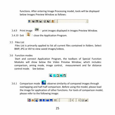
3.4.8 Image Process / Exit Image Process : image processing include reversed video, grey scale, black and white, edge detection and other basic
25
functions. After entering Image Processing model, tools will be displayed below Images Preview Window as follows:
3.4.9 Print Image :print images displayed in Images Preview Window.
3.4.10 Exit :close the Application Program.
3.5 Files List
Files List is primarily applied to list all current files contained in folders. Select BMP, JPG or AVI to view saved images/videos.
3.6 Function modes
Start and connect Application Program, the toolbars of Special Function Modules will show below the Video Preview Window; which includes: comparison, aming mode, image control, measurement and far distance control mode. See below:
3.6.1 Comparison mode : observe similarity of compared images through overlapping and half-half comparison. Before using the model, please load the image for application of other functions. For tools of comparison model, please refer to the following image:
26
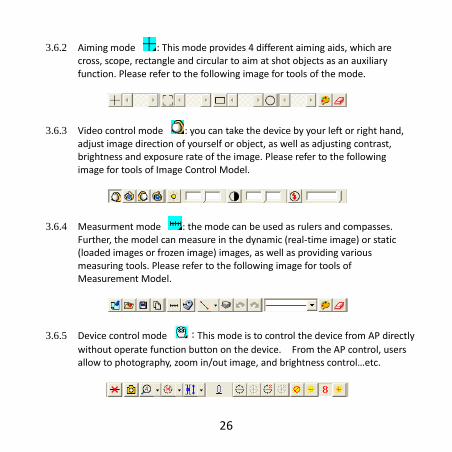
3.6.2 Aiming mode : This mode provides 4 different aiming aids, which are cross, scope, rectangle and circular to aim at shot objects as an auxiliary function. Please refer to the following image for tools of the mode.
3.6.3 Video control mode : you can take the device by your left or right hand, adjust image direction of yourself or object, as well as adjusting contrast, brightness and exposure rate of the image. Please refer to the following image for tools of Image Control Model.
3.6.4 Measurment mode : the mode can be used as rulers and compasses. Further, the model can measure in the dynamic (real-time image) or static (loaded images or frozen image) images, as well as providing various measuring tools. Please refer to the following image for tools of Measurement Model.
3.6.5 Device control mode :This mode is to control the device from AP directly
without operate function button on the device. From the AP control, users allow to photography, zoom in/out image, and brightness control…etc.

27
4. Printed Notice Please read the following information before operate.
4.1 Maintenance Please abide by the following items while storing or using the product:
4.1.1 Keep dry: do not place the product in a humid environment. Dry surroundings are helpful to extend the life of the product.
4.1.2 Avoid temperature shock: temperature shock will cause internal condensation inside the machine, for example, take the product into a warm room from cold environment. Please put the machine inside the protection bag or handbag in advance to prevent temperature shock, and avoid using the machine in an environment with over-high/low temperature.
4.1.3 Avoid collision and drop: the product might go wrong by strong collision, vibration or distortion.
4.1.4 Turn off the microscope before cutting off the power supply: do not forced cut off the power supply.
4.1.5 Do not make face lens against strong light or sunshine for long time: Strong light rays might degrade sensitive elements and generate white stain on the image.
4.1.6 Handle movable LED cover and other parts carefully: do not force disassemble USB Cable, HDMI cable or power supplier. Avoid contacting the lens since they are subjected to damage.
4.1.7 Machine not in operation for period: please switch off power supply and unplug power cable, and store them in a dry place with excellent ventilation. Do not expose the machine in an environment lower than -5℃ or higher than
50℃
4.1.8 Appropriate storage: while carrying, please put the machine inside the box to
prevent it from being damaged because of collision.

28
4.2 Product Specification
CMOS Sensor 5 million pixels CMOS senor
Lens Object lens 4X: 4/0.10,160/0.17; Object lens 10X: 10/0.25,160/0.17
Magnification Object lens 4X: 15x~270x; Object lens 10X: 260x~900x on 21.5” screen
Auxiliary source
White LED × 30pcs
DC port Adaptor DC input
HDMI port Output 1080P(1920*1080 Pixel) image
USB port USB 2.0,3.0 compatible, connect with PC.
Focus control IR remote controller/PC(application program) control
Power supplier
adaptor (input:DC 5.0V/2.0A input:AC 100-240V 50/60Hz)
Electric Consumption
5V/1200mA
Size 106(L)×106(W)×152(T) mm
Weight Host weight around 310 grams
Operation environment
Temperature -5℃ ~ 50℃; Humidity-lower than 85% (No
Condensation)
For any change, please visit http://www.vitiny.com

29
4.3 Safety Instructions
As an electronic product, please do not use the machine in any place in which all electronic products are prohibited or required to shut off electronic products.
Please do not make the machine close to water source or wet since it is not waterproof. Avoid electric shock.
Do not make the machine close to chemicals, objects with explosive hazard or fire sources. Please switch off the product in gas station.
In case that there is foreign body, water inside the machine, the machine drops off, or the housing is damaged, please switch off power supply and remove power supply to avoid fire and electric shock.
Do not look steadily at auxiliary sources after switching on the host as it is harmful to your eyes.
Please use related product accessories provided in the box for connecting. Do not use any product in connection on your own without approval of original factory.
Please remove power supplier from microscope if not using for period. Do not disassemble the machine for inspection on your own. For any problem
occurred in the machine itself, please switch off the machine and then contact us by e-mail to the following address: [email protected]

30

ViTiny UM06 Warranty P r o d u c t Model no S/L nos. P u rc h a s e d a t e
DD/MM/YYYY
Purchaser T e l n o : A d d r e s s
Email Distributor Seal for Confirmation
( Stamp is necessary for validation of the Warranty )
※Distributor’s seal shall include name of the shop, telephone and address※
Please ask the distributor to fill in the name of the shop, address, purchase date and other contents and seal to protect your rights and validate one-year warranty since upon the purchase date. Contents of Warranty: The Warranty is only provided free of charge for faults caused by the manufacturing within one year since upon the purchase date. Non-warranty: 1. Product appearance parts, such as outer casing, knobs and LED cover, etc
(charged spare parts are limited to one year after completing the product manufacturing).
2. Consumption goods of the host itself, such a, LED lights and lens. 3. Product accessories and fittings, such as power supplier, USB cable, HDMI cable,
calibrator, white balance card, remote controller…etc. Services caused by any of the following situations in the period of the warranty shall not be provided free of charge: 1. Improper using or self (entrust any other with) disassembly, repair or refitting. 2. Any fault or damaged machine caused by act of god, lightning strike, abnormal
voltage or environmental factors, etc. Discrepancy of product serial number, unfilled Warranty, or unreal fill-in, alteration or unidentified Warranty. Any inspection and repair service after the period of warranty will be charged as follows according to the situation: (1) Service fees (including transportation fees) of product inspection. (2) Repair fees. (3) Fees of replaced parts
ViTiny Service Center Tel: 07-657-9551 Fax: 07-657-9561 Address: 10 F., No.1, Section 1, Syuecheng Road, Dashu District, Kaohsiung City 840, Taiwan (R.O.C.)
Website: http://www.vitiny.com

